medical imaging x-rays i. principle of x-ray a source of radiation
TRANSCRIPT

Medical Imaging
X-Rays I
Principle of X-ray
A source of radiation

Principle of X-ray
A source of radiation
A patient of non uniformsubstance

Principle of X-ray
A source of radiation
A patient of non uniformsubstance
A shadow
Principle of X-ray
A source of radiation
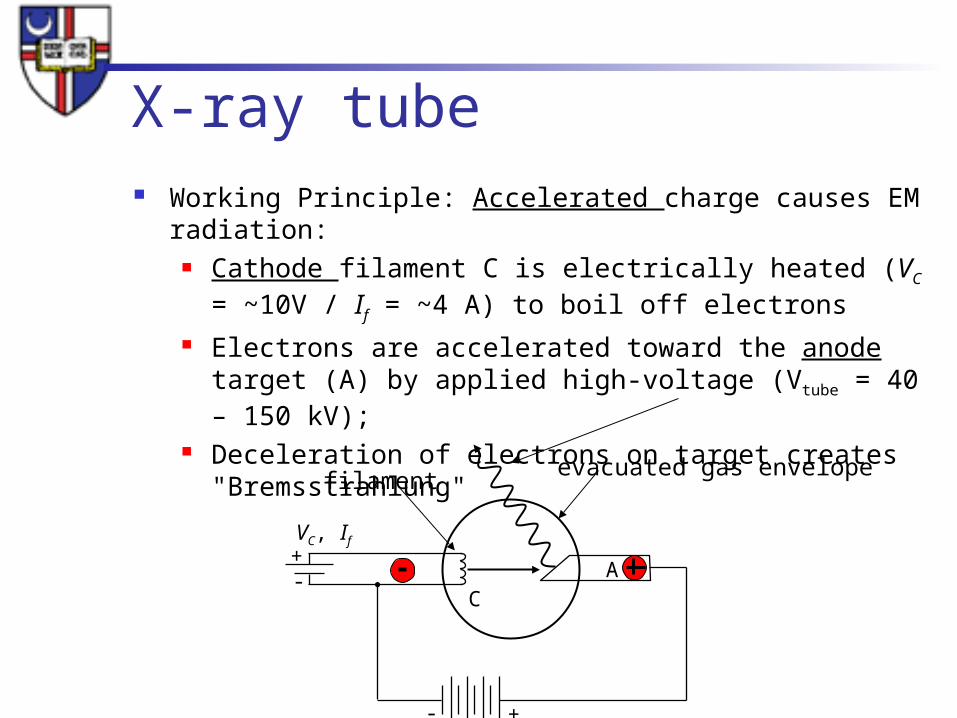
X-ray tube Working Principle: Accelerated charge causes EM radiation:
Cathode filament C is electrically heated (VC = ~10V / If = ~4 A) to boil off electrons
Electrons are accelerated toward the anode target (A) by applied high-voltage (Vtube = 40 – 150 kV);
Deceleration of electrons on target creates "Bremsstrahlung"
+-
CA
VC, If
+-
filamentevacuated gas envelope

X-ray tube Cathode Filament (-)
Coil of tungsten wire High resistance in coil ->temperature rise to > 2200oC Thermionic emission of electrons
Tube (vacuum) Typical: Vtube = 40 – 150 kVp, Itube = 1-1000mA
+-
kVp, Itube
CA
VC, If
+-
filamentevacuated gas envelope
-
--
-
-
-- - -
space chargestops further emission

X-ray tube Anode
Tungsten (high atomic number Z=74) Electrons striking the anode generate HEAT and X-Rays In mammography ->Molybdenium (Z=42) and Rhodium (Z=45) Stationary anode-> tungsten embedded in copper Rotating anode (3000 to 10,000rpm) -> increase heat capacity,
target area
+-
kVp, Itube
CA
VC, If
+-
filamentevacuated gas envelope
-
--
-
-
-- - -
space charge

XRAY PRODUCTION

X-RAY production
X-ray tube produces two forms of radiation
Bremsstrahlung radiation (white radiation)
Characteristic radiation

White radiation, Bremsstrahlung
X-Ray
Coulombic interaction
-Inelastic interaction with atoms nuclei-Loss of kinetic energy-Xray (E) = lost kinetic E
-High kinetic energy-Forward radiation
-Emission Z2
(Atomic number)# of protons
(Brake)
electron
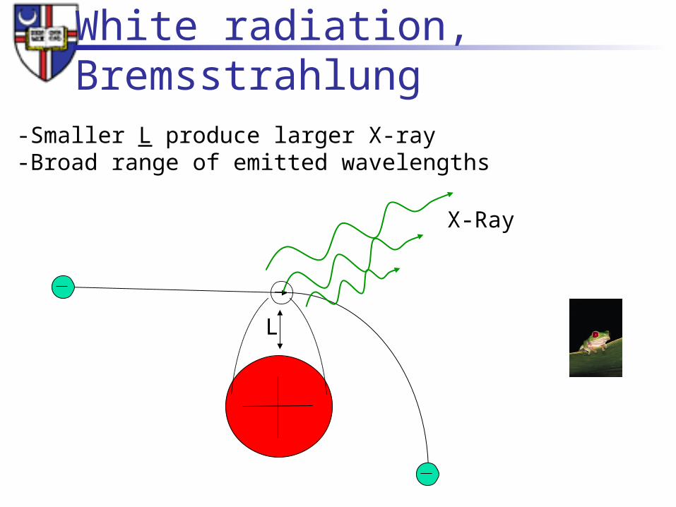
White radiation, Bremsstrahlung
X-Ray
L
-Smaller L produce larger X-ray-Broad range of emitted wavelengths

How many wavelength will be emitted by a beam of
electrons underegoing “Bremsstrahlung ”

White radiation, Bremsstrahlung
X-Ray
L
-Smaller L produce larger X-ray-Broad range of emitted wavelengths
maximum energy
impact with nucleus

X-ray intensity -QUANTITY
Overall Bremsstrahlung intensity I :
90% of electrical energy supplied goes to heat, 10% to X-ray production
X-ray production increases with increasing voltage V
€
I ∝Vtube2 Itube

Bremsstrahlung spectrum Theoretically, bremsstrahlung from a
thick target creates a continuous spectrum from E = 0 to Emax
Actual spectrum deviates from ideal form due to Absorption in window / gas
envelope material and absorption in anode
Multienergetic electron beam
Peak voltage kVp
relative output

Characteristic radiation Energy must be > binding energy
Discrete energy peaks due to electrons transitions
K transition L->K
K transition M,N,O->K
Peak voltage kVp
relative output
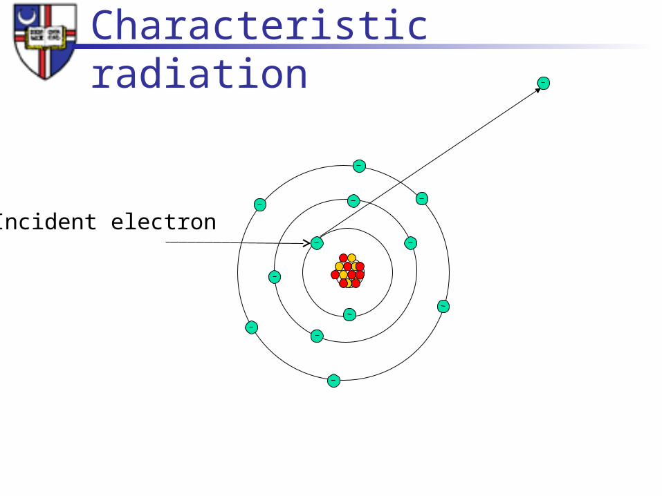
Characteristic radiation
Incident electron

Characteristic radiation
Incident electron
Occurs only at discrete levelsThere is a possibility of forming Auger electrons

Characteristic radiation•In Tungsten characteristic X-ray are formed only if V>69.5 kV because K shell binding energy is 69.5 keV
•Molybdenum K-shell can be obtained at V> 20kV
•L shell radiation is also produced but it’s low energy and oftenabsorbed by glass enclosure

X-ray intensity -QUALITY
Effective photon energy produced Effective = ability to penetrate the patient Effective photon energy ~ 1/3 to ½ of energy
produced Higher energy better penetration Beam filtration – beam hardening

Beam Hardening
Polyenergetic beam ------------------------------->monoenergetic beam

X-ray tube construction

Anode
Most of the energy deposited on the anode transfersinto heat

Reduction of anode heating Made of Tungsten, high melting
point high atomic number Z = 74
€
Radiative enegy loss
Collisional energy loss=
EkZ
820,000
€
100 ⋅74
820,000= 0.009 → 0.9% Xray production
99% Heat production
€
6,000 ⋅74
820,000≅ 0.54 → 54 % Xray production
46 % Heat production
100keV electron
6 MeV electron
Kinetic energy of incident electrons

Anode the target angle, 7 to 20 (average 12)
Seffective = Sactual*sin() -----------> Line focusing principle

Anode filament balance
General radiography
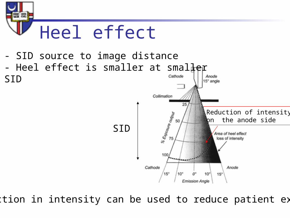
Heel effect
Reduction of intensityon the anode side
SID
- SID source to image distance- Heel effect is smaller at smallerSID
The reduction in intensity can be used to reduce patient exposure

Beam collimation Size and shape of the beam Lead shutters Dose reduction

Reduction of anode heating
Anode angle of 7º…15º results in apparent or effective spot size Seffective much smaller than the actual focal spot of the electron beam (by factor ~10)
Rotation speed ~ 3000 rpm
Decreases surface area for heat dissipation from by a factor of 18-35.

Limitations of anode angle Restricting target coverage for
given source-to-image distance (SID)
"Heel effect" causes inhomogeneous x-ray exposure

X-ray tube - space charge
-Space charge cloud forms at low tube voltage-At low filament current a saturation voltage is achieved, rising tube voltage will not generate higher electron flow -At high filament current and low tube voltage, space charge limits tube current->space-charge limit

Space charge limited At high filament current and low tube voltage, space charge limits tube
current->space-charge limit

Generator Single phase
Single phase input (220V, 50A) Single pulse or double pulse->rectifier Min exposure time 1/120 sec Xray tube current non linear below 40kV
Three phase Three phase wave, out of phase 120 deg More efficient higher voltage Better control on exposure

RectifierProtects cathode from anode thermionic emission

Rectifier
1 phase
3 phase

BREAK!

Principle of X-ray
A source of radiation
A patient of non uniformsubstance

Attenuation N
No
L
L1
N
Loss of photons by scattering or absorption
N = Noe-L
L1
-> linear attenuationcoefficient
True for monoenergetic x-ray

linear attenuation coeff.
= r+ ph+ c+ p [cm-1] rayleigh
photoelectric
Compton
pair
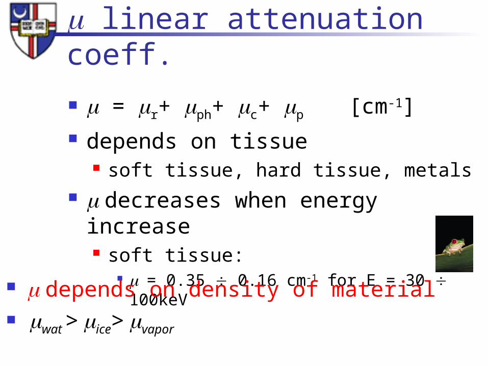
linear attenuation coeff.
= r+ ph+ c+ p [cm-1] depends on tissue
soft tissue, hard tissue, metals decreases when energy increase
soft tissue: = 0.35 0.16 cm-1 for E = 30 100keV
depends on density of material wat > ice> vapor
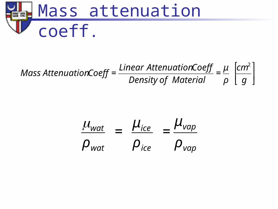
Mass attenuation coeff.
€
Mass Attenuation Coeff =Linear Attenuation Coeff
Density of Material=
μ
ρ
cm2
g
⎡
⎣ ⎢
⎤
⎦ ⎥
€
wat
ρ wat
= μ ice
ρ ice
=μ vap
ρ vap

Mass attenuation coeff.N = Noe- (L
L = mass thickness

Mass attenuation coeff.N = Noe- (L
L = mass thickness
I
x
Poly-energetic beam
Mass attenuation coefficient and linear attenuation coefficient are for mono-energetic beam
Half-value layer is for quantifying poly-energetic beams

HVL half value layer Thickness of material attenuating the
beam of 50% - narrow beam geometry
HVL for soft tissue is 2.5 3.0 cm at diagnostic energies
€
HVL=lnlinear
cm[ ]
HVL half value layer Transmission of primary beam:
10% chest radiography 1% scull radiography 0.5% abdomen radiography Mammography (low energy HVL 1 cm)
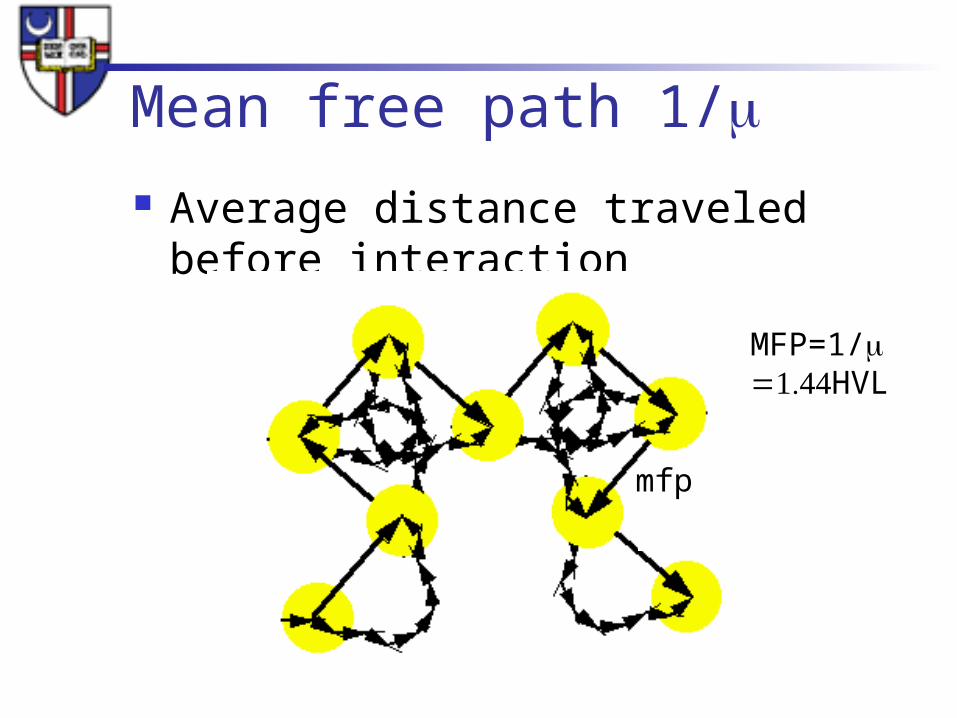
Mean free path 1/ Average distance traveled before interaction
mfp
MFP=1/HVL

Principle of X-ray
A source of radiation
A patient of non uniformsubstance
A shadow