mediant™ family of media gateways & sbcs -...
TRANSCRIPT

Release Notes
AudioCodes Family of Media Gateways & Session Border Controllers (SBC)
Mediant™ Family of Media Gateways & SBCs
Version 7.2

Version 7.2 3 Mediant Gateways & SBCs
Release Notes Contents
Table of Contents 1 Introduction ......................................................................................................... 9
1.1 Products Supported in Release 7.2 .......................................................................... 9 1.2 Software Revision Record ...................................................................................... 10
2 New Products and Platforms ........................................................................... 11
2.1 Media Transcoder Device ...................................................................................... 11
3 Released Versions ............................................................................................ 13
3.1 Version GA ............................................................................................................. 13 3.1.1 New Software Features .......................................................................................... 13
3.1.1.1 New GUI for Web-based Management Tool ........................................... 13 3.1.1.2 New CLI Structure ................................................................................... 13 3.1.1.3 Interworking between SIP and SIP-I Endpoints ...................................... 14 3.1.1.4 Maximum Call Duration per Gateway and SBC Calls ............................. 14 3.1.1.5 Protection against Known Malicious Attacks ........................................... 15 3.1.1.6 Block SIP Requests from Registered Users when Address Different ..... 16 3.1.1.7 Enhanced Dialog Classification Based on Proxy Set .............................. 17 3.1.1.8 Wildcard Denoting 18x Responses in Message Manipulation Rules ...... 17 3.1.1.9 Increase in Maximum SIP Message Size ................................................ 17 3.1.1.10 IP Group Keep-Alive Connectivity Status Indication ............................... 17 3.1.1.11 Enhanced Configuration of Allowed Coder Groups ................................. 18 3.1.1.12 Enhanced Audio Coder Groups Configuration ........................................ 19 3.1.1.13 Enhanced Dial Plan Tagging ................................................................... 19 3.1.1.14 Increase in Maximum Network Interfaces ............................................... 20 3.1.1.15 CDR Local Storage for Gateway Calls .................................................... 20 3.1.1.16 Historical CDRs Display for SBC Calls .................................................... 20 3.1.1.17 New CDR Fields ...................................................................................... 20 3.1.1.18 Maximum RADIUS Requests .................................................................. 21 3.1.1.19 Increase in Maximum Network ACL Rules .............................................. 21 3.1.1.20 Enhanced TLS Certificate Support .......................................................... 21 3.1.1.21 TLS Certificate Verification ...................................................................... 22 3.1.1.22 Disable Reuse of TLS Connections......................................................... 22 3.1.1.23 UDP Port Spacing by Four ...................................................................... 22 3.1.1.24 Sending of Silence RTP Packets to SIP Trunks ...................................... 22 3.1.1.25 Media Transcoding Cluster Feature ........................................................ 23 3.1.1.26 New Quality of Service PMs and Alarms ................................................. 25 3.1.1.27 Actions upon Poor Voice Quality Detections ........................................... 26 3.1.1.28 Bitrate Configuration for SILK and Opus Coders .................................... 27 3.1.1.29 Core Dump File Deletion ......................................................................... 27
3.1.2 Known Constraints .................................................................................................. 28 3.1.3 Resolved Constraints .............................................................................................. 33
3.2 Patch Version 7.20A.001 ........................................................................................ 34 3.2.1 New Features .......................................................................................................... 34
3.2.1.1 New Virtualized Platforms for Mediant VE SBC ...................................... 34 3.2.1.2 Enhanced Dial Plan Tags and Call Setup Rules ..................................... 34 3.2.1.3 Enhanced SIP-SIP-I Interworking ............................................................ 35 3.2.1.4 Triggering Special Call Actions using X-AC-Action SIP Header ............. 35 3.2.1.5 VoIPerfect Feature .................................................................................. 36
4 Session Capacity .............................................................................................. 39
4.1 Signaling, Media and User Registration Capacity .................................................. 39 4.2 Mediant 500 E-SBC ................................................................................................ 42 4.3 Mediant 500L Gateway and E-SBC ....................................................................... 42

Release Notes 4 Document #: LTRT-26970
Mediant Gateways & SBCs
4.4 Mediant 800/B Gateway & E-SBC .......................................................................... 43 4.5 Mediant 1000B Gateway & E-SBC ......................................................................... 46
4.5.1 Analog (FXS/FXO) Interfaces ................................................................................. 46 4.5.2 BRI Interfaces ......................................................................................................... 47 4.5.3 E1/T1 Interfaces ...................................................................................................... 48 4.5.4 Media Processing Interfaces ................................................................................... 49
4.6 Mediant 2600 E-SBC .............................................................................................. 50 4.7 Mediant 4000 SBC ................................................................................................. 51 4.8 Mediant 4000B SBC ............................................................................................... 53 4.9 Mediant 9000 SBC ................................................................................................. 55 4.10 Mediant 9000 SBC with Media Transcoders .......................................................... 56 4.11 Mediant Server Edition SBC ................................................................................... 58 4.12 Mediant Virtual Edition SBC ................................................................................... 58
4.12.1 Mediant VE SBC for KVM and VMware Hypervisors .............................................. 58 4.12.1.1 2-vCPU Mediant VE SBC ........................................................................ 58 4.12.1.2 4-vCPU Mediant VE SBC ........................................................................ 60 4.12.1.3 Amazon AWS EC2 .................................................................................. 61 4.12.1.4 8-vCPU Mediant VE SBC ........................................................................ 62
4.12.2 Mediant VE SBC for Hyper-V Hypervisor ............................................................... 64 4.12.2.1 2-vCPU Mediant VE SBC ........................................................................ 64 4.12.2.2 4-vCPU Mediant VE SBC ........................................................................ 65
5 Obsolete Features and Parameters ................................................................ 67
5.1 SAS Application ...................................................................................................... 67 5.2 Obsolete Parameters ............................................................................................. 68

Version 7.2 5 Mediant Gateways & SBCs
Release Notes Contents
List of Tables Table 1-1: Products Supported in Release 7.2 ........................................................................................ 9 Table 1-2: Software Revision Record .................................................................................................... 10 Table 3-1: Known Constraints in Release 7.2 ....................................................................................... 28 Table 3-2: Resolved Constraints in Release 7.2 ................................................................................... 33 Table 4-1: Maximum Signaling, Media Sessions and Registered Users ............................................... 39 Table 4-2: Mediant 500 E-SBC (Non Hybrid) SBC Capacity ................................................................. 42 Table 4-3: Mediant 500 Hybrid E-SBC (with Gateway) Media & SBC Capacity ................................... 42 Table 4-4: Mediant 500L E-SBC (Non Hybrid) SBC Capacity ............................................................... 42 Table 4-5: Mediant 500L Hybrid E-SBC (with Gateway) Media & SBC Capacity ................................. 42 Table 4-6: Mediant 800/B Gateway & E-SBC SBC Session Capacity per Capabilities (SBC Only) ..... 43 Table 4-7: Mediant 800/B Gateway & E-SBC Channel Capacity per Capabilities (with Gateway) ....... 43 Table 4-8: Channel Capacity per DSP Firmware Template for Mediant 1000B Analog Series ............ 46 Table 4-9: Channel Capacity per DSP Firmware Template for Mediant 1000B BRI Series ................. 47 Table 4-10: Channel Capacity per DSP Firmware Templates for Mediant 1000B E1/T1 Series .......... 48 Table 4-11: Channel Capacity per DSP Firmware Template for Mediant 1000B MPM Series ............. 49 Table 4-12: Channel Capacity per Coder-Capability Profile for Mediant 2600 E-SBC ......................... 50 Table 4-13: Channel Capacity per Coder-Capability Profile for Mediant 4000 SBC ............................. 51 Table 4-14: Channel Capacity per Coder-Capability Profile for Mediant 4000B SBC ........................... 53 Table 4-15: Channel Capacity per Coder-Capability Profile for Mediant 9000 SBC ............................. 55 Table 4-16: Channel Capacity per Detection Feature for Mediant 9000 SBC....................................... 56 Table 4-17: Transcoding Capacity per Profile for a Single Media Transcoder ...................................... 56 Table 4-18: Channel Capacity for 2-vCPU Mediant VE SBC on KVM/VMware .................................... 58 Table 4-19: Channel Capacity per Detection Feature for 2-vCPU Mediant VE SBC on KVM/VMware 59 Table 4-20: Channel Capacity for 4-vCPU Mediant VE SBC on KVM/VMware .................................... 60 Table 4-21: Channel Capacity per Detection Feature for 4-vCPU Mediant VE SBC on KVM/VMware 61 Table 4-22: Channel Capacity for Mediant VE SBC on Amazon EC2 .................................................. 61 Table 4-23: Channel Capacity per Detection Feature for Mediant VE SBC on Amazon EC2 .............. 62 Table 4-24: Channel Capacity for 8-vCPU Mediant VE SBC on KVM/VMware .................................... 62 Table 4-25: Channel Capacity per Detection Feature for 8-vCPU Mediant VE SBC on KVM/VMware 63 Table 4-26: Channel Capacity for 2-vCPU Mediant VE SBC on Hyper-V ............................................. 64 Table 4-27: Channel Capacity per Detection Feature for 2-vCPU Mediant VE SBC on Hyper-V ......... 65 Table 4-28: Channel Capacity for 4-vCPU Mediant VE SBC on Hyper-V ............................................. 65 Table 4-29: Channel Capacity per Detection Feature for 4-vCPU Mediant VE SBC on Hyper-V ......... 66 Table 5-1: Obsolete Parameters ............................................................................................................ 68

Release Notes 6 Document #: LTRT-26970
Mediant Gateways & SBCs
This page is intentionally left blank.

Version 7.2 7 Mediant Gateways & SBCs
Release Notes Notices
Notice This document describes the new features of Release 7.2 for AudioCodes Session Border Controllers (SBC), and SIP-based Voice-over-IP (VoIP) analog and digital Media Gateways. Information contained in this document is believed to be accurate and reliable at the time of printing. However, due to ongoing product improvements and revisions, AudioCodes cannot guarantee accuracy of printed material after the Date Published nor can it accept responsibility for errors or omissions. Updates to this document and other documents as well as software files can be downloaded by registered customers at http://www.audiocodes.com/downloads.
© Copyright 2016 AudioCodes Ltd. All rights reserved. This document is subject to change without notice.
Date Published: July-11-2016
Trademarks AudioCodes, AC, HD VoIP, HD VoIP Sounds Better, IPmedia, Mediant, MediaPack, What’s Inside Matters, OSN, SmartTAP, VMAS, VoIPerfect, VoIPerfectHD, Your Gateway To VoIP, 3GX, VocaNom and CloudBond 365 are trademarks or registered trademarks of AudioCodes Limited All other products or trademarks are property of their respective owners. Product specifications are subject to change without notice.
WEEE EU Directive Pursuant to the WEEE EU Directive, electronic and electrical waste must not be disposed of with unsorted waste. Please contact your local recycling authority for disposal of this product.
Customer Support Customer technical support and services are provided by AudioCodes or by an authorized AudioCodes Service Partner. For more information on how to buy technical support for AudioCodes products and for contact information, please visit our Web site at www.audiocodes.com/support.
Abbreviations and Terminology Each abbreviation, unless widely used, is spelled out in full when first used. Throughout this manual, unless otherwise specified, the term device refers to the AudioCodes products.

Release Notes 8 Document #: LTRT-26970
Mediant Gateways & SBCs
Related Documentation
Document Name
Mediant 500 E-SBC Hardware Installation Manual
Mediant 500 E-SBC User's Manual
Mediant 800B Gateway and E-SBC Hardware Installation Manual
Mediant 800B Gateway and E-SBC User’s Manual
Mediant 1000B Gateway and E-SBC Hardware Installation Manual
Mediant 1000B Gateway and E-SBC User’s Manual
Mediant 2600 E-SBC Hardware Installation Manual
Mediant 2600 E-SBC User’s Manual
Mediant 4000 SBC Hardware Installation Manual
Mediant 4000 SBC User’s Manual
Mediant 9000 SBC User’s Manual
Mediant 9000 SBC Hardware Installation Manual
Mediant SE SBC Installation Manual
Mediant VE SBC Installation Manual
Mediant Server & Virtual Editions SBC User’s Manual
CLI Reference Guide
Document Revision Record
LTRT Description
26957 Initial document release for Version 7.2.
26963 Capacity updated for Mediant 9000, Mediant 4000/B detection features, and Mediant 9000 with Media Transcoders.
26968 Mediant VE High-Capacity VMware capacity; Mediant 500L Gateway & E-SBC capacity (hybrid).
26969 Patch version 7.20A.001; Typo in Mediant 4000B SBC capacity table.
26970 Patch version 7.20A.001 updates: Mediant VE SBC virtual platforms (Amazon EC2 and SR-IOV); Registered users capacity updated for 1/2/4 vCPU 4 GB RAM Hyper-V; Capacity added for Amazon EC2 and SR-IOV.
Documentation Feedback AudioCodes continually strives to produce high quality documentation. If you have any comments (suggestions or errors) regarding this document, please fill out the Documentation Feedback form on our Web site at http://www.audiocodes.com/downloads.

Version 7.2 9 Mediant Gateways & SBCs
Release Notes 1. Introduction
1 Introduction This document describes the release of Version 7.2. This includes new products, new hardware features, new software features, known constraints, and resolved constraints.
Notes:
• Some of the features mentioned in this document are available only if the relevant Software License Key has been purchased from AudioCodes and is installed on the device. For a list of available Software License Keys that can be purchased, please contact your AudioCodes sales representative.
• Open source software may have been added and/or amended. For further information, visit AudioCodes Web site at http://audiocodes.com/support or contact your AudioCodes sales representative.
• Updates to this document may be made due to significant information discovered after the release or too late in the release cycle to be otherwise included in this release documentation. You can check for an updated version on AudioCodes Web site as a registered customer at http://www.audiocodes.com/downloads.
1.1 Products Supported in Release 7.2 Products (new and existing) supported in this release are listed in the table below:
Table 1-1: Products Supported in Release 7.2
Product Telephony Interfaces Ethernet
Interfaces USB OSN FXS/FXO BRI E1/T1
Mediant 500 E-SBC - - 1/1 4 GE 2 -
Mediant 500L Gateway & E-SBC - 4 - 4 FE 1 -
Mediant 800B Gateway & E-SBC 12/12 8 2 4 GE / 8 FE 2 √
Mediant 1000B Gateway & E-SBC 24/24 20 6/8 61 - √
Mediant 2600 E-SBC - - - 8 GE - -
Mediant 4000 SBC - - - 8 GE - -
Mediant 4000B SBC - - - 8 GE - √
Mediant 9000 SBC - - - 12 GE - -
Mediant SE SBC - - - 12 GE - -
Mediant VE SBC - - - 12 GE - -
Note:
• Product support and hardware configurations may change without notice. Currently available hardware configurations are listed in AudioCodes Price Book. For further enquiries, please contact your AudioCodes sales representative.
• Figures listed above are maximum values per interface. For available hardware configurations including combinations of supported interfaces, contact your AudioCodes sales representative.
1 Two ports on the CRMX module and four ports on the optional LAN Expansion module.

Release Notes 10 Document #: LTRT-26970
Mediant Gateways & SBCs
1.2 Software Revision Record The following table lists the software versions released in Version 7.2.
Table 1-2: Software Revision Record
Software Version Date
Beta Version (7.20A.000.042) April 2016
7.20A.001 July 2016

Version 7.2 11 Mediant Gateways & SBCs
Release Notes 2. New Products and Platforms
2 New Products and Platforms This chapter describes new products and platforms introduced in Release 7.2.
2.1 Media Transcoder Device AudioCodes' Media Transcoder (MT) delivers high-capacity DSP-based transcoding in conjunction with AudioCodes’ field-proven SBC product family (currently, supported only by Mediant 9000 SBC) enabled with the Media Transcoding Cluster feature. AudioCodes MT is a modular solution, supporting up to three field-upgradable transcoding modules in a single 1-U chassis. As transcoding needs increase, multiple AudioCodes MT devices can be added to form a cluster configuration giving virtually unlimited scalability along with HA cluster redundancy. The main hardware specifications of the Media Transcoder include: 1U chassis design, suitable for 19-inch rack mounting Eight 100/1000Base-T Ethernet ports, supporting 1+1 Ethernet port redundancy Dual Power Supply modules, providing power load sharing and AC power redundancy Modular scalability from one to up to three MPM12B DSP modules For more information on the Media Transcoding Cluster feature, see Section 3.1.1.25 on page 23.

Release Notes 12 Document #: LTRT-26970
Mediant Gateways & SBCs
This page is intentionally left blank.

Version 7.2 13 Mediant Gateways & SBCs
Release Notes 3. Released Versions
3 Released Versions 3.1 Version GA
This section describes new features, known constraints and resolved constraints for the GA version.
3.1.1 New Software Features New features introduced in the GA version include the following:
3.1.1.1 New GUI for Web-based Management Tool This feature introduces a new graphical user interface (GUI) for the device's Web-based management tool (Web interface). The new GUI offers the following new features: New modern look-&-feel design, making configuration more intuitive and improving
user experience. Topology view showing a graphical display of the core SIP configuration entities (IP
Groups, SIP Interfaces, Media Realms, and Trunk Groups), enabling the administrator to easily build and view the SIP topology.
Network view showing a graphical display of the core networking entities (IP interfaces, Ethernet Devices, Ethernet Groups, and Physical Ethernet ports), enabling the administrator to easily build and view the main network topology.
Improved navigation to Web pages, facilitating configuration. Indication icons of configured table rows. Navigation pane and tables display icons
indicating the number of configured table rows, invalid row configuration, and invalid associations with other table rows.
Easy access to associated configuration entities while configuring an entity. Fewer user clicks to save configuration and reset device. Quick access to vital call statistics. Search based on strings and IP address. Applicable Products: All. Applicable Application: Gateway and SBC.
3.1.1.2 New CLI Structure This feature introduces a new structure of the CLI that is more aligned with the hierarchical structure of the navigation tree of the new Web GUI launched in this version. The modified structure allows faster and easier navigation between commands in the CLI. The CLI provides fewer folders, allowing the administrator to access commands with fewer key strokes. Many command names have also been made more concise to eliminate visual "clutter". The CLI commands are now organized under the following main folders: configure system: Contains system-related commands (e.g., clock, snmp
settings and web) configure network: Contains IP network-related commands (e.g., interface,
dhcp-server and nfs) configure voip: Contains voice-over-IP related commands (e.g., ip-group, sbc,
gateway and media) configure troubleshoot: Contains logging-related commands (e.g., syslog,

Release Notes 14 Document #: LTRT-26970
Mediant Gateways & SBCs
logging and test-call) The debugging-related commands are located under the root directory for quick access. Applicable Products: All. Applicable Application: Gateway and SBC.
3.1.1.3 Interworking between SIP and SIP-I Endpoints This feature provides support for interworking between SIP and SIP-I endpoints for SBC calls. SIP-I is a flavor of the SIP protocol, which carries a message body consisting of the User Part of the ISDN protocol (or ISDN User Part - ISUP) over IP networks. SIP-I endpoints are entities that are connected to the SS7 network, referred to as the ISDN user part (ISUP) domain. The device supports the SIP-I Application-layer signaling protocol, which is a standard for encapsulating a complete copy of the SS7 ISUP message in SIP messages, according to ITU-T Q.1912.5, Interworking between Session Initiation Protocol (SIP) and Bearer Independent Call Control protocol or ISDN User Part. For the interworking process, the device maps between ISUP data and SIP headers. For example, the E.164 number in the Request-URI of the outgoing SIP INVITE is mapped to the Called Party Number parameter of the IAM message and the From header of the outgoing INVITE is mapped to the Calling Party Number parameter of the IAM message. The ISUP data is included in SIP messages using the Multipurpose Internet Mail Extensions (MIME) body part, The feature also introduces support for manipulating ISUP data, using the existing Message Manipulations table. For a complete description of the ISUP manipulation syntax, refer to the SIP Message Manipulation Reference Guide. To support the feature, the following new parameter has been added:
ISUP Body Handling sbc-isup-body-handling [IpProfile_SBCISUPBodyHandling]
Defines the handling of ISUP data for interworking between SIP and SIP-I. [0] Transparent = (Default) ISUP data is passed
transparently (as is) between endpoints (SIP-I to SIP-I calls). [1] Remove = Delete the ISUP body from the INVITE
message. [2] Create = Adds ISUP body to outgoing INVITE message.
Note: For more information on the feature, please contact your AudioCodes sales representative. Applicable Products: All. Applicable Application: SBC.
3.1.1.4 Maximum Call Duration per Gateway and SBC Calls This feature provides support for configuring the maximum call duration for SBC and Gateway calls. Up until this release, maximum call duration could only be configured globally and applied to all calls for both applications—Gateway and SBC—using the MaxCallDuration parameter (which is now obsolete). The feature allows the administrator to configure maximum call duration for the following: SBC calls:
• All SBC calls (i.e., globally) • Specific SBC calls (using IP Profiles)
Gateway calls: All Gateway calls (globally) only The feature is useful for ensuring that calls are properly terminated, making device resources available for new calls. To support the feature, the following new parameters have been added:
SBC Max Call Duration sbc-mx-call-duration
Defines the maximum duration (in minutes) for each SBC call (global). If the duration is reached, the device terminates the call.

Version 7.2 15 Mediant Gateways & SBCs
Release Notes 3. Released Versions
[SBCMaxCallDuration] The valid range is 0 to 35,791, where 0 is unlimited duration. The default is 0. Note: The parameter replaces the MaxCallDuration parameter.
Max Call Duration sbc-max-call-duration [IpProfile_SBCMaxCallDuration]
Defines the maximum duration (in minutes) for each SBC call that is associated with the IP Profile. If the duration is reached, the device terminates the call. The valid range is 0 to 35,791, where 0 is unlimited duration. The default is the value configured for the SBCMaxCallDuration parameter.
GW Max Call Duration gw-mx-call-duration [GWMaxCallDuration]
Defines the maximum duration (in minutes) for each Gateway call (global). If the duration is reached, the device terminates the call. The valid range is 0 to 35,791, where 0 is unlimited duration. The default is 0. Note: The parameter replaces the MaxCallDuration parameter.
Applicable Products: All. Applicable Application: Gateway and SBC.
3.1.1.5 Protection against Known Malicious Attacks This feature provides support for protecting the device against malicious attacks on SBC calls using a Malicious Signature database. The feature allows the administrator to configure a database of malicious signature patterns which identify specific scanning tools used by attackers to search for a SIP server in a network. The feature identifies and protects against SIP (Layer 5) threats by examining any new inbound SIP dialog message. Once the device identifies an attack based on the configured malicious signature patterns, it marks the SIP message as invalid and discards it or alternatively, rejects it with a SIP response (by default 400). The malicious signatures are based on the SIP User-Agent header and employ the same syntax used for Message Manipulation rules. For example: Malicious signature is defined as follows for a malicious scanner:
header.user-agent.content prefix “malicious scanner”
Malicious signature is defined as follows for the scanning tool "sip-scan": Header.User-Agent.content prefix 'sip-scan'
The protection applies only to new dialogs (e.g., INVITE messages) and unauthenticated dialogs. The Malicious Signature database does not apply to the following: Calls from IP Groups where classification is by Proxy Set. In-dialog SIP sessions (such as refresh REGISTER requests, re-INVITE etc.) Calls from users that are registered with the device. By default, the device is installed with a list of known attackers, called the Malicious Signature Database. The Malicious Signature database is presented in table format. The administrator can add, edit or delete entries. As a safety mechanism, if all entries are deleted and the device is subsequently reset, the table is populated again with all the signatures. In addition, the administrator can export or import a Malicious Signature database through HTTP, HTTPS, or TFTP. The feature is enabled by a new global parameter (see below). The existing Message Policy table provides an additional default Message Policy rule for the Malicious Signature database ("MaliciousSignatureDBProtection"). To apply the Malicious Signature database to calls, the administrator needs to associate this default Message Policy rule to an SBC SIP Interface in the existing SIP Interface table. The Malicious Signature database can also be used with the existing Intrusion Detection System (IDS) feature. A new IDS reason has been added to denote Malicious Signature detections (Signature DB invalid). This allows the administrator to enable SNMP alarm generation ("Dialog establishment failure") if any signature is detected by the device.

Release Notes 16 Document #: LTRT-26970
Mediant Gateways & SBCs
To support the feature, the following new parameters have been added:
Malicious Signature Table [MaliciousSignatureDB]
Defines up to 30 malicious signature patterns (rows). [ MaliciousSignatureDB ] FORMAT MaliciousSignatureDB_Index = MaliciousSignatureDB_Name, MaliciousSignatureDB_Pattern; [ \MaliciousSignatureDB ]
Message Policy Table [MessagePolicy_UseMaliciousSignatureDB]
New parameter: Malicious Signature Database [MessagePolicy_UseMaliciousSignatureDB] = Enables the use of the Malicious Signature database for SIP Interfaces that are assigned the Message Policy.
configure voip > sbc malicious-signature-database <export-csv-to | import-csv-from> <URL>
Exports/imports a Malicious Signature database file (in *.csv format) to/from a server (HTTP, HTTPS, or TFTP).
Applicable Products: Mediant 5xx; Mediant 8xx; Mediant 1000B; Mediant 2600; Mediant 4000; Mediant 9000; Mediant SE/VE. Applicable Application: SBC.
3.1.1.6 Block SIP Requests from Registered Users when Address Different This feature provides support for blocking (rejecting) SIP dialog-initiating requests (such as INVITE messages) from a user that is registered with the device, but where the source address (IP address and/or port) and transport type (e.g., UDP) is different to that registered for the user (during the REGISTER message process). When the device rejects a request, it reports the rejection (Classification failure) through the already supported Intrusion Detection System (IDS), by sending an SNMP trap. The device can verify whether the IP address and port are different only if the transport protocol is UDP; otherwise, the device verifies only the IP address. The verification is performed before any of the device's call handling processes (i.e., Classification, Manipulation and Routing) and applies only to User-type IP Groups. Note that the feature does not apply to registration refreshes. These requests are accepted even if their source address is different to that registered for the user. To support the feature, the following existing parameters have been modified:
User Security Mode [SRD_BlockUnRegUsers]
Parameter name and optional values modified: Defines the blocking (reject) policy of incoming SIP dialog-initiating requests from users (except REGISTER requests). When the device rejects a request, it sends a SIP 500 "Server Internal Error" response to the user. [0] Accept All = (Default) Accepts requests from registered
and unregistered users. [1] Accept Registered Users = Accepts requests from
registered users only and rejects requests from users not registered with the device.
[2] Accept Registered Users from Same Source = Accepts requests only from registered users whose source address is the same as that registered with the device. All other requests are rejected.
User Security Mode [SIPInterface_BlockUnRegUsers]
Parameter name and optional values modified: Defines the blocking (reject) policy of incoming SIP dialog-initiating requests from users (except REGISTER requests). When the device rejects a request, it sends a SIP 500 "Server Internal Error" response to the user. [-1] Not Configured (default) [0] Accept All = Accepts requests from registered and

Version 7.2 17 Mediant Gateways & SBCs
Release Notes 3. Released Versions
unregistered users. [1] Accept Registered Users = Accepts requests from
registered users only and rejects requests from users not registered with the device.
[2] Accept Registered Users from Same Source = Accepts requests only from registered users whose source address is the same as that registered with the device. All other requests are rejected.
Applicable Products: All. Applicable Application: SBC.
3.1.1.7 Enhanced Dialog Classification Based on Proxy Set This feature provides support for enhanced classification of incoming SIP dialogs to IP Groups, based on Proxy Set when multiple Proxy Sets are configured with the same IP address. For more information, refer to the User's Manual. Applicable Products: All. Applicable Application: SBC.
3.1.1.8 Wildcard Denoting 18x Responses in Message Manipulation Rules The feature provides support for using the 'x' wildcard in SIP message manipulation rules to denote all SIP 18x responses (e.g., 180, 181, 182 and 183). The wildcard is used in the 'Message Type' field, which defines the type of message to which the manipulation is applied. For example, to configure a rule that applies to any SIP 18x in response to an INVITE message, the following syntax is used in the 'Message Type' field: invite.response.18x
Up until this release, the exact 18x response (e.g., 180, 181, 182 or 183) had to be specified. For example, if the administrator wanted to apply the same message manipulation to all 18x responses, multiple rules with the same syntax except for the specified 18x response had to be configured. Applicable Products: All. Applicable Application: Gateway and SBC.
3.1.1.9 Increase in Maximum SIP Message Size This feature provides support for configuring the existing parameter, MaxSIPMessageLength to up to 100 KB. The device rejects SIP messages exceeding the configured size. Up until this release, the maximum SIP message size could be configured to 50 KB. Applicable Products: All. Applicable Application: Gateway and SBC.
3.1.1.10 IP Group Keep-Alive Connectivity Status Indication This feature provides support for displaying the connectivity status of Server-type IP Groups. As the Proxy Set defines the actual address of the IP Group, the connectivity check (or keep-alive) by the device is done to this address. Note that for the feature to be relevant, the keep-alive mechanism must be enabled for the associated Proxy Set (using the existing parameter, ProxySet_EnableProxyKeepAlive). The connectivity status is indicated as follows: Topology View: The status is displayed as a color-coded icon in the IP Group element:

Release Notes 18 Document #: LTRT-26970
Mediant Gateways & SBCs
• Green: Keep-alive is successful (i.e., connectivity with IP Group). Note that if the device rejects calls destined to this IP Group due to low QoE (e.g., low MOS), the indication still appears green.
• Red: Keep-alive failure (i.e., no connectivity with IP Group). An example of these icons is shown below:
IP Group table: The status is displayed in the new read-only field, 'Proxy Set
Connectivity' (IPGroup_ProxySetConnectivity ini parameter or show voip proxy sets status CLI command):
• "NA": Functionality is not applicable in the following cases: ♦ If Server-type IP Group and the Proxy Keep-Alive mechanism is disabled ♦ If User-type IP Group
• "Not Connected": Keep-alive failure (i.e., no connectivity with IP Group) • "Connected": Keep-alive is successful (i.e., connectivity with IP Group)
Applicable Products: All. Applicable Application: Gateway and SBC.
3.1.1.11 Enhanced Configuration of Allowed Coder Groups This feature provides support for enhanced configuration design of Allowed Audio Coder Groups and Allowed Video Coder Groups: Allowed Audio Coder Groups: User-defined coders can now be configured through the
Web interface. Up until now, it could only be configured through ini file and CLI. In addition, configuration now consists of two tables – parent and child. The parent table configures the ID and name; the child configures the coders of the selected group.
Allowed Video Coder Groups: Now configurable through the Web interface. Up until this release, Allowed Video Coders Groups could only be configured through ini file and CLI.
Allowed Audio Coders Groups configure voip > coders-and-profiles allowed-audio-coders-groups [AllowedAudioCodersGroups]
Parent table that defines the names of the Allowed Audio Coder Groups. [ AllowedAudioCodersGroups ] FORMAT AllowedAudioCodersGroups_Index = AllowedAudioCodersGroups_Name; [ \AllowedAudioCodersGroups ]
Allowed Audio Coders coders-and-profiles allowed-audio-coders <group index/coder index> [AllowedAudioCoders]
Child table of the Allowed Audio Coders Groups that defines the audio coders of the group. [ AllowedAudioCoders ] FORMAT AllowedAudioCoders_Index = AllowedAudioCoders_AllowedAudioCodersGroupName, AllowedAudioCoders_AllowedAudioCodersIndex, AllowedAudioCoders_CoderID, AllowedAudioCoders_UserDefineCoder; [ \AllowedAudioCoders ]
Allowed Video Coders Groups configure voip > coders-and-profiles allowed-video-coders-groups
[AllowedVideoCodersGroups]
Parent table that defines the names of the Allowed Video Coder Groups. [ AllowedVideoCodersGroups ] FORMAT AllowedVideoCodersGroups_Index = AllowedVideoCodersGroups_Name; [ \AllowedVideoCodersGroups ]
Allowed Video Coders coders-and-profiles
Child table of the Allowed Video Coders Groups that defines the video coders of the group.
Version 7.2 19 Mediant Gateways & SBCs
Release Notes 3. Released Versions
allowed-video-coders <group index/coder index>
[AllowedVideoCoders]
[ AllowedVideoCoders ] FORMAT AllowedVideoCoders_Index = AllowedVideoCoders_AllowedVideoCodersGroupName, AllowedVideoCoders_AllowedVideoCodersIndex, AllowedVideoCoders_UserDefineCoder; [ \AllowedVideoCoders ]
Applicable Products: All. Applicable Application: SBC.
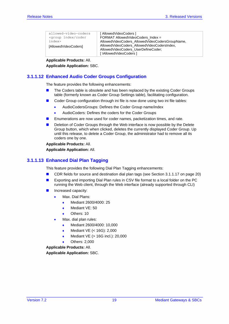
3.1.1.12 Enhanced Audio Coder Groups Configuration The feature provides the following enhancements: The Coders table is obsolete and has been replaced by the existing Coder Groups
table (formerly known as Coder Group Settings table), facilitating configuration. Coder Group configuration through ini file is now done using two ini file tables:
• AudioCodersGroups: Defines the Coder Group name/index • AudioCoders: Defines the coders for the Coder Groups
Enumerations are now used for coder names, packetization times, and rate. Deletion of Coder Groups through the Web interface is now possible by the Delete
Group button, which when clicked, deletes the currently displayed Coder Group. Up until this release, to delete a Coder Group, the administrator had to remove all its coders one by one.
Applicable Products: All. Applicable Application: All.
3.1.1.13 Enhanced Dial Plan Tagging This feature provides the following Dial Plan Tagging enhancements: CDR fields for source and destination dial plan tags (see Section 3.1.1.17 on page 20) Exporting and importing Dial Plan rules in CSV file format to a local folder on the PC
running the Web client, through the Web interface (already supported through CLI) Increased capacity:
• Max. Dial Plans: ♦ Mediant 2600/4000: 25 ♦ Mediant VE: 50 ♦ Others: 10
• Max. dial plan rules: ♦ Mediant 2600/4000: 10,000 ♦ Mediant VE (< 16G): 2,000 ♦ Mediant VE (> 16G incl.): 20,000 ♦ Others: 2,000
Applicable Products: All. Applicable Application: SBC.

Release Notes 20 Document #: LTRT-26970
Mediant Gateways & SBCs
3.1.1.14 Increase in Maximum Network Interfaces This feature provides support for an increase in the maximum number of IP network interfaces that can be configured in the IP Interfaces table (InterfaceTable). The increase is from 100 to 1024 network interfaces. The maximum capacity of Media Realms and Ethernet Devices that can be configured in the Media Realms table (CpMediaRealm) and Ethernet Devices table (DeviceTable) were also increased to 1,024. Applicable Products: Mediant 9000; Mediant VE/SE. Applicable Application: SBC.
3.1.1.15 CDR Local Storage for Gateway Calls This feature provides support for CDR local storage for Gateway calls. Up until now, CDR local storage was supported only for SBC calls. Configuration for CDR local storage is the same as SBC (CDRLocalMaxFileSize, CDRLocalMaxNumOfFiles, and CDRLocalInterval) and Logging Filters table for selectively enabling the feature. Due to the feature, customization of locally stored Gateway CDRs is also supported. As a result, the new optional value Local Storage Gateway [9] has been added to the 'CDR Type' (GWCDRFormat_CDRType) parameter in the Gateway CDR Format table. Applicable Products: Mediant 5xx; Mediant 8xx; Mediant 1000B. Applicable Application: Gateway.
3.1.1.16 Historical CDRs Display for SBC Calls This feature provides support for displaying historical CDRs (last 4,096 CDRs) for SBC calls in the device's management interfaces. Up until now, historical CDRs were displayed for Gateway calls only. To support the feature, the new table, SBC CDR History has been added: Web: Monitor menu > Monitor tab > VoIP Status folder > SBC CDR History CLI: show voip calls history sbc The table includes the following CDR fields: Call End Time, IP Group, Caller, Callee, Direction, Remote IP, Duration, Termination Reason, and Session. The name of the existing CDR History table for Gateway calls has been changed to Gateway CDR History: Web: Monitor menu > Monitor tab > VoIP Status folder > GW CDR History CLI: show voip calls history gw Applicable Products: All. Applicable Application: Gateway and SBC.
3.1.1.17 New CDR Fields This feature introduces the following new CDR fields: LegId: Identifies each leg by a unique ID number within a specific call session. The
field is assigned a unique number for each leg in the call session. This unique identification enhances the ability of applications such as AudioCodes SEM to analyze call data according to various segments in the call session.
Trigger: Describes the reason of the call. The field name can be customized, using the Gateway CDR Format and SBC CDR Format tables. The tables show the field as "Trigger" (ini file enumeration 439) in the 'Field Type' field. The field can have one of the following values: • "Normal": regular call • "Refer": call as a result of call transfer

Version 7.2 21 Mediant Gateways & SBCs
Release Notes 3. Released Versions
• "AltRoute": call as a result of alternative routing • "Forward": call as a result of forwarded call • "Reroute": call re-routed due to a voice issue (e.g., broken RTP connection) • "Forking": call as a result of call forking
SrcDialPlanTags / DestDialPlanTags: Indicate Dial Plan tags (source and destination) used for the call (if the Dial Plan Tagging feature is implemented). The field name can be customized using the SBC CDR Format table. The table shows the field as "Source Dial Plan Tags" (ini file enumeration 816) and "Destination Dial Plan Tags" (ini file enumeration 817) in the 'Field Type' field.
Note that the ini file enumerations of the optional values in the 'Field Type' field of the Gateway and SBC CDR Format tables have changed. Applicable Products: All. Applicable Application: Gateway and SBC.
3.1.1.18 Maximum RADIUS Requests The feature provides support for an increase in the maximum number of RADIUS requests that the device can send simultaneously to a RADIUS server. Up until this release, the device could send only up to 254 concurrent RADIUS requests (RADIUS Accounting and Authentication together). This feature provides the following support: All Products: Up to 201 concurrent RADIUS requests per RADIUS service type
(Accounting or Authentication) and per RADIUS server (up to three servers per service type).
Mediant 2600, Mediant 4000, Mediant 9000 and Mediant SW Only: Up to 201 concurrent RADIUS requests per RADIUS service type (Accounting or Authentication), per RADIUS server and per local port, which has been increased from one port to the following: • Mediant 2600/4000: two local ports • Mediant 9000/SW: four local ports • For all other products: only one port is supported. For example, for Mediant 4000, 402 (201 * 2) concurrent RADIUS requests can be sent for Authentication and 402 (201 * 2) for Accounting. These numbers are per RADIUS server.
Applicable Products: All. Applicable Applications: SBC and Gateway.
3.1.1.19 Increase in Maximum Network ACL Rules This feature provides support for an increase in the maximum number of network Access Control List (ACL) or firewall rules that can be configured in the Firewall table (AccessList). The increase is from 50 to 500 rules. Applicable Products: Mediant 2600; Mediant 4000; Mediant 9000; Mediant VE/SE. Applicable Application: SBC.
3.1.1.20 Enhanced TLS Certificate Support This feature provides support for the following TLS enhancements: Private Key size (in bits): The private key size can now be configured to 4096 bits,
which provides very high strength key. Up until this release, the key size options were 512, 768, 1024, and 2048. The private key size is configured by the existing parameter, Private Key Size (Web - TLS Contexts page > TLS Context Certificate link; CLI - configure network > tls > private-key generate).

Release Notes 22 Document #: LTRT-26970
Mediant Gateways & SBCs
Signature algorithm for certificates: The signature algorithm can now be configured to SHA-256 or SHA-512. Up until this release, the device supported only the SHA-1 algorithm (default). The algorithm is configured by the new parameter, Signature Algorithm (Web - TLS Contexts page > TLS Context Certificate link; CLI - configure network > tls > certificate signature-algorithm).
Enabling validation of extensions (keyUsage and extentedKeyUsage) of peer certificates is now configured per TLS Context. Up until this release, it was configured globally. To support the feature, the global parameter, RequireStrictCert has been replaced by the new TLS Context table parameter, TLSContexts_RequireStrictCert.
Configuring the TLS Server Certificate Expiry Check feature per TLS Context. Up until this release, it was configured globally for all TLS Contexts. (No change in parameters.)
Applicable Products: All. Applicable Application: Gateway and SBC.
3.1.1.21 TLS Certificate Verification This feature provides a change in support for verifying the address in the TLS certificate received from a Server-type IP Group whose Proxy Set is configured as an FQDN. Up until now, the device verified that the DNS-resolved IP address of the FQDN matched the IP address in the certificate. Now, the device verifies that the FQDN of the Proxy Set matches the FQDN in the certificate. The feature is enabled by the existing parameter, PeerhostNameVerificationMode. Applicable Products: All. Applicable Application: SBC.
3.1.1.22 Disable Reuse of TLS Connections This feature provides support for disabling the use of the same TLS connection for new SIP requests between the device and a SIP user agent (UA). Up until this release, the device always used the same TLS connection (successful handshake) that was established in the initial SIP dialog request, for subsequent requests (e.g., INVITE or REGISTER) sent to the UA. The feature is supported by the existing parameter, EnableTCPConnectionReuse, which up until this release, was applicable only to TCP. Applicable Products: All. Applicable Application: Gateway and SBC.
3.1.1.23 UDP Port Spacing by Four This feature provides support for local UDP port allocation in "jumps" (spacing) of four. Up until this release, UDP port spacing could be configured to 5 or 10. The device allocates ports for a media channel (leg) from a pool of UDP ports. The pool starts from a port configured by the existing parameter, BaseUDPPort and each leg is assigned several consecutive ports for its usage (e.g. RTP, RTCP, and T.38). The spacing between ports per leg is configured by the existing parameter, UdpPortSpacing. For example, if port spacing is configured to four and BaseUDPPort to 6000, the allocated ports are 6000 for the first leg, 6004 for the second leg, 6008 for the third leg, and so on. (For all other products, UDP port spacing is 10 as supported in previous releases). Applicable Products: Mediant 2600; Mediant 4000; Mediant 9000; Mediant VE/SE. Applicable Application: SBC.
3.1.1.24 Sending of Silence RTP Packets to SIP Trunks The feature provides support for the device to interoperate with SIP entities (e.g., SIP Trunks) that wait for the first incoming packet before sending RTP (e.g., early media used for ringback tone and IVR) during media negotiation. The feature enables the device to

Version 7.2 23 Mediant Gateways & SBCs
Release Notes 3. Released Versions
generate "silence" RTP packets to the SIP entity upon receipt of a SIP response (183 with SDP) from the SIP entity. In other words, these packets serve as the first incoming packets for the SIP entity. The device stops sending the silence packets when it receives RTP packets from the peer side (which it then forwards to the SIP entity). Note: To generate silence packets, DSP resources are required (except for calls using G.711).
Generate RTP sbc-generate-rtp
[IPProfile_SBCGenerateRTP]
Enables generation of silence RTP packets until audio RTP packets are detected. [0] None (Default) = No silence packets are generated. [1] Until RTP Detected = Silence packets are generated
Applicable Products: All. Applicable Application: SBC.
3.1.1.25 Media Transcoding Cluster Feature The feature provides support for the SBC device (Mediant 9000) to use an external source of DSP resources for media-related features requiring DSPs, for example, vocodec transcoding, fax transcoding, and DTMF detection. The external farm (cluster) of DSP resources is provided by AudioCodes transcoding devices (up to six), called Media Transcoders. The SBC device itself functions as the cluster manager and does not perform any transcoding (does not utilize any of its local DSP resources). The Media Transcoders provide only DSP functionality (i.e., no SIP routing functionalities) and a few system functionalities such as debugging through Syslog. The Media Transcoders are "hidden" from the endpoints being serviced by the device. The Media Transcoding Cluster feature is a licensed feature, requiring the SBC device to be installed with a suitable License Key. The device with the Cluster Manager functionality can still operate as a High-Availability (HA) system. If a switchover occurs, transcoding sessions handled by the Media Transcoding Cluster are maintained.
The main benefit of the Media Transcoding Cluster feature is scalability. The Media Transcoder doesn’t require licensing of its transcoding resources and allows utilization of all its DSP resources. However, the maximum possible transcoding capacity by the SBC device is according to the License Key of the SBC device, regardless of the number of deployed Media Transcoders.
Release Notes 24 Document #: LTRT-26970
Mediant Gateways & SBCs
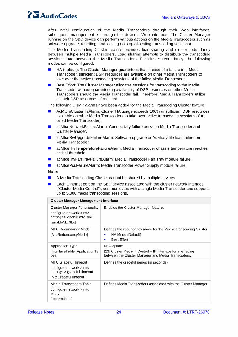
After initial configuration of the Media Transcoders through their Web interfaces, subsequent management is through the device's Web interface. The Cluster Manager running on the SBC device can perform various actions on the Media Transcoders such as software upgrade, resetting, and locking (to stop allocating transcoding sessions). The Media Transcoding Cluster feature provides load-sharing and cluster redundancy between multiple Media Transcoders. Load sharing attempts to distribute the transcoding sessions load between the Media Transcoders. For cluster redundancy, the following modes can be configured: HA (default): The Cluster Manager guarantees that in case of a failure in a Media
Transcoder, sufficient DSP resources are available on other Media Transcoders to take over the active transcoding sessions of the failed Media Transcoder.
Best Effort: The Cluster Manager allocates sessions for transcoding to the Media Transcoder without guaranteeing availability of DSP resources on other Media Transcoders should the Media Transcoder fail. Therefore, Media Transcoders utilize all their DSP resources, if required.
The following SNMP alarms have been added for the Media Transcoding Cluster feature: AcMtcmClusterHaAlarm: Cluster HA usage exceeds 100% (insufficient DSP resources
available on other Media Transcoders to take over active transcoding sessions of a failed Media Transcoder).
acMtceNetworkFailureAlarm: Connectivity failure between Media Transcoder and Cluster Manager.
acMtceSwUpgradeFailureAlarm: Software upgrade or Auxiliary file load failure on Media Transcoder.
acMtceHwTemperatureFailureAlarm: Media Transcoder chassis temperature reaches critical threshold.
acMtceHwFanTrayFailureAlarm: Media Transcoder Fan Tray module failure. acMtcePsuFailureAlarm: Media Transcoder Power Supply module failure. Note: A Media Transcoding Cluster cannot be shared by multiple devices. Each Ethernet port on the SBC device associated with the cluster network interface
(“Cluster-Media-Control”), communicates with a single Media Transcoder and supports up to 5,000 media transcoding sessions.
Cluster Manager Management Interface
Cluster Manager Functionality configure network > mtc settings > enable-mtc-sbc [EnableMtcSbc]
Enables the Cluster Manager feature.
MTC Redundancy Mode [MtcRedundancyMode]
Defines the redundancy mode for the Media Transcoding Cluster. HA Mode (Default) Best Effort
Application Type [InterfaceTable_ApplicationTypes]
New option: [23] Cluster Media + Control = IP interface for interfacing between the Cluster Manager and Media Transcoders.
MTC Graceful Timeout configure network > mtc settings > graceful-timeout [MtcGracefulTimeout]
Defines the graceful period (in seconds).
Media Transcoders Table configure network > mtc entity [ MtcEntities ]
Defines Media Transcoders associated with the Cluster Manager.

Version 7.2 25 Mediant Gateways & SBCs
Release Notes 3. Released Versions
Transcoding Cluster Log Displays logged activities of Media Transcoders and Cluster Managers.
Media Transcoders Management Interface
Cluster Manager IP Address [ClusterManagerIpAddress]
Defines the Cluster Manager by IP address of the corresponding cluster interface (Cluster Media + Control network interface).
Applicable Products: Mediant 9000. Applicable Application: SBC.
3.1.1.26 New Quality of Service PMs and Alarms The feature provides support for new quality-of-service performance monitoring (PM) call metrics that can be calculated by the device. The metrics measure network quality and call success rates and are calculated globally, per SRD and per IP Group. Answer-seizure ratio (ASR): The number (in percentage) of answered calls (i.e.
number of seizures resulting in an answer signal) out of the total number of attempted calls (seizures). The metric is calculated for the outgoing call leg. Note that forwarded calls are not considered in the calculation. The PMs related to the metric include: • PM_gwSBCASR: ASR for all (global) entities (i.e., all IP Groups and SRDs) • PM_gwSBCIPGroupASR: ASR per IP Group • PM_gwSBCSRDASR: ASR per SRD
Network Effectiveness Ratio (NER): The number (in percentage) of successfully connected calls out of the total number of attempted calls (seizures). The metric measures the ability of the network to deliver a call to the called terminal. In addition to answered calls, the following response codes are regarded as successfully connected calls: 408 (Request Timeout), 480 (Temporarily Unavailable), and 486 (Busy Here). The metric is calculated for the outgoing call leg. Note that forwarded calls are not considered in the calculation. The PMs related to the metric include: • PM_gwSBCNER: NER for all (global) entities (i.e., all IP Groups and SRDs) • PM_gwSBCIPGroupNER: NER per IP Group • PM_gwSBCSRDNER: NER per SRD
Average Call Duration (ACD): The ACD plus the session disconnect time (SDD) is the time from when the SIP 200 OK is received to when the SIP Bye message is sent. The metric is calculated for both the incoming and outgoing call legs. The PMs related to the metric include: • PM_gwSBCACD: ACD for all (global) entities (i.e., all IP Groups and SRDs) • PM_gwSBCIPGroupACD: ACD per IP Group • PM_gwSBCSRDACD: ACD per SRD
Minor and major thresholds can be configured per metric (in the new table, Performance Profile table - see below) that if crossed, minor and major severity alarms are generated. The following new SNMP alarms are supported: acASRThresholdAlarm (OID 1.3.6.1.4.1.5003.9.10.1.21.2.0.111): The alarm is raised
when the configured ASR minor and major thresholds are crossed. AcNERThresholdAlarm (OID 1.3.6.1.4.1.5003.9.10.1.21.2.0.113): The alarm is raised
when the configured NER minor and major thresholds are crossed. acACDThresholdAlarm (OID 1.3.6.1.4.1.5003.9.10.1.21.2.0.112): The alarm is raised
when the configured ACD minor and major thresholds are crossed. To support the feature, the following new table has been added:
Performance Profile table configure system > performance-profile
Defines alarm thresholds per metric (ASR, ACD and NER). [ PerformanceProfile ] FORMAT PerformanceProfile_Index =

Release Notes 26 Document #: LTRT-26970
Mediant Gateways & SBCs
[ PerformanceProfile ] PerformanceProfile_Entity, PerformanceProfile_IPGroupName, PerformanceProfile_SRDName, PerformanceProfile_PMType, PerformanceProfile_MinorThreshold, PerformanceProfile_MajorThreshold, PerformanceProfile_Hysteresis, PerformanceProfile_MinimumSample, PerformanceProfile_WindowSize; [ \PerformanceProfile ]
Applicable Products: All. Applicable Application: SBC.
3.1.1.27 Actions upon Poor Voice Quality Detections The feature supports configuration of actions that must be performed if poor quality of experience is detected. Configuration is based on Quality of Service rules, using the new Quality of Service Rules table. The following actions can be performed: Reject calls to an IP Group for a user-defined duration if a user-defined threshold
(major or minor) of a specified metric is crossed. The metric can be voice quality (i.e., MOS), bandwidth (supported in the previous release), ASR, NER, or ACD. When the device rejects calls to an IP Group based on a QoS rule, the device raises the new SNMP alarm, acIpGroupNoRouteAlarm (OID 1.3.6.1.4.1.5003.9.10.1.21.2.0.114). When the device rejects a call due to an ASR, NER or ACD threshold crossing, it sends the new SIP response, 850 (Signaling Limits Exceeded). This SIP response code has been added to the Alternative Routing Reasons table (SBCAlternativeRoutingReasons). If it is configured and the device rejects a call due to threshold crossing, it searches in the IP-to-IP Routing table for an alternative routing rule.
Use an alternative IP Profile for the IP Group upon threshold crossings of voice quality or bandwidth. The alternative IP Profile can be used: • For all new calls: If poor voice quality or bandwidth threshold is crossed, the
alternative IP Profile is used for all new calls. All the parameters of the alternative IP Profile can be configured.
As a result of the feature, the MediaEnhancementProfile and MediaEnhancementRules tables are now obsolete.
Quality of Service Rules Table configure voip > qoe quality-of-service-rules
[ QualityOfServiceRules ]
Defines Quality of Service rules. [ QualityOfServiceRules ] FORMAT QualityOfServiceRules_Index = QualityOfServiceRules_IPGroupName, QualityOfServiceRules_RuleMetric, QualityOfServiceRules_Severity, QualityOfServiceRules_RuleAction, QualityOfServiceRules_CallsRejectDuration, QualityOfServiceRules_AltIPProfileName; [ \QualityOfServiceRules ]
Applicable Products: All. Applicable Application: SBC.

Version 7.2 27 Mediant Gateways & SBCs
Release Notes 3. Released Versions
3.1.1.28 Bitrate Configuration for SILK and Opus Coders The feature provides support for configuring the bitrate of the Opus coder. In addition, the default of the existing SilkMaxAverageBitRate parameter, which configures the bitrate for the SILK coder has changed to 50,000.
Opus Max Average Bitrate configure voip > sip-definition settings > opus-max-avg-bitrate
[OpusMaxAverageBitRate]
Defines the maximum average bit rate (bps) for the Opus coder. The valid value range is 6000 to 50,000. The default is 50,000.
Applicable Products: All. Applicable Application: SBC.
3.1.1.29 Core Dump File Deletion This feature provides support for deleting the core dump file from the device's flash memory through CLI. As supported in the previous release, the core dump file is created by the device upon device crash (enabled by the EnableCoreDump parameter) and is a copy of the memory image of the device at the time of the crash. To support the feature, the following new command has been added under the root CLI directory (enable mode): # clear debug-file
Applicable Products: All. Applicable Application: Gateway and SBC.

Release Notes 28 Document #: LTRT-26970
Mediant Gateways & SBCs
3.1.2 Known Constraints This chapter lists known constraints in Release 7.2.
Table 3-1: Known Constraints in Release 7.2
Incident Description
134449 RADIUS-based authentication of SIP users and RADIUS-based authentication of login username and password for management users are currently not supported. Applicable Products: Mediant 2600; Mediant 4000.
- The SIPRec feature is not supported when the Media Transcoding Cluster feature is used. Applicable Products: Mediant 9000.
132977 To upgrade from software version 7.0 to 7.2, the device must first be upgraded to the latest 7.0 version (later than 7.00A.058.002) and only then to version 7.2. Applicable Products: Mediant 2600; Mediant 4000; Mediant 9000; Mediant SE/VE.
133943 SRTP with ARIA encryption is not supported for SBC sessions. Applicable Products: All.
- ARM is not supported. Applicable Products: All.
131889 When importing a Dial Plan file (*.csv file), it is recommended to configure the SyslogDebugLevel parameter to No Debug. Applicable Products: All.
116756 The device interworks with devices that support RTP bundling. However, it does not support receipt of bundled multimedia sessions on the same port and instead, it uses different ports for each media type (audio and video). By default, the device removes all bundle-related attributes ('a=group:BUNDLE' and 'a=ssrc') from the SDP offer and answer. Applicable Products: All.
- CLI scripts used in Version 6.8 are not fully supported and need to be modified in order to be fully compatible in Version 7.2. Applicable Products: All.
- Downgrade from Version 7.2 to a previous software version only works if the device was upgraded to Version 7.2 and no configuration changes were done after the upgrade. Applicable Products: All.
- The combination of SBC direct media and termination features such as the handling of 3xx, REFER, and INVITE with Replaces is supported only if all SIP user agents support INVITE/re-INVITE without SDP, and terminations of semi-attendant transfer and INVITE with Replaces during call ringing is not supported with direct media. Applicable Products: All.
- SBC Delayed SDP offer is supported only by devices that support DSP transcoding. Applicable Products: All.
- High Availability (HA) for WebRTC and One-Voice Resiliency is not fully supported (signaling may not function correctly in certain scenarios). Applicable Products: HA-Supporting Devices.

Version 7.2 29 Mediant Gateways & SBCs
Release Notes 3. Released Versions
Incident Description
- The SBC User Info table limits the maximum number of users that can be configured (half of the maximum per device). Applicable Products: All.
- Out-of-dialog SIP REFER message for SBC calls is forwarded transparently; the subsequent NOTIFY message is not fully supported. Applicable Products: All.
- Transrating of G.711, G.726, and G.729 for SBC calls from packetization time (ptime) 100/120 msec to 10/30/50 msec is not supported. Applicable Products: Mediant 1000B.
- When SBC termination features are used so that the device handles them locally (i.e., 'Remote Can Play Ringback', 'Play Held Tone', and 'Play RBT To Transferee'), Extension Coders Group ID must be configured, even if only one coder is used. This is especially relevant for the RBT to transferee feature. Applicable Products: All.
- Ring to Hunt Group feature does not function when early media is used. Applicable Products: Mediant 8xx.
- For the Tel-to-IP Call Forking feature (supported by the Gateway application), if a domain name is used as the destination in the Tel to IP Routing table, the maximum number of resolved IP addresses supported by the device's internal DNS that the call can be forked to is three (even if four IP addresses are defined for the domain name). Applicable Products: Mediant 5xx; Mediant 8xx; Mediant 1000B.
- The AT&T toll free out-of-band blind transfer for trunks configured with the 4ESS ISDN protocol can only be configured using ini file parameters. Applicable Products: Mediant 8xx; Mediant 1000B.
- When using the DSP Cluster feature, the local DSP resources on the SBC cannot be utilized. Applicable Products: Mediant 9000; Mediant VE.
- When SRTP is enabled, RTP Redundancy and M-factor cannot operate together. In other words, SRTP can operate with RTP Redundancy greater than 0 or with m-factor greater than 1, but not with both. Applicable Products: Mediant 1000B.
- When IP-to-IP or IP-to-PSTN calls use SRTP with ARIA encryption, the number of simultaneous calls is limited to 31. Applicable Products: Mediant 5xx; Mediant 8xx.
- SBC RTP call forwarding using the SRTP tunneling feature cannot provide RTCP XR monitoring parameters (such as MOS) required for the QoE feature on the following variable bit rate coders: G.723, GSM FR, GSM EFR, MS RTA, EVRC, AMR, QCELP, and Speex. A workaround is to use SRTP full encryption / decryption on the forwarding calls. Applicable Products: Mediant 1000B GW & E-SBC.
- Ethernet packets received on the RTP side of SRTP-RTP SBC sessions must not exceed 1500 bytes. Packets exceeding this size are dropped. Applicable Products: Mediant 5xx; Mediant 8xx; Mediant 1000B; Mediant Non-Hybrid SBC.

Release Notes 30 Document #: LTRT-26970
Mediant Gateways & SBCs
Incident Description
The device does not support the sending of RFC 2198 RTP redundancy packets as an operation if the configured packet loss threshold is exceeded; this is configured in the Quality Of Experience Web page. Applicable Products: All.
- The Transparent coder (RFC 4040) poses the following limitations: The coder can be used only when using physical terminations No detection of IBS (e.g., DTMF) Generation of IBS is only toward the network No fax/modem detection or generation (i.e., no support for T.38 and Bypass) A workaround for this constraint is to use the G.711 coder instead. Applicable Products: Mediant 5xx; Mediant 8xx; Mediant 1000B.
- The RFC 2198 Redundancy mode with RFC 2833 is not supported (i.e., if a complete DTMF digit is lost, it is not reconstructed). The current RFC 2833 implementation supports redundancy for lost inter-digit information. Since the channel can construct the entire digit from a single RFC 2833 end packet, the probability of such inter-digit information loss is very low. Applicable Products: Mediant 5xx; Mediant 8xx.
- The duration resolution of the On and Off time digits when dialing to the network using RFC 2833 relay is dependent on the basic frame size of the coder being used. Applicable Products: Mediant 5xx; Mediant 8xx; Mediant 1000B.
- The Calling Tone (CNG) detector must be set to Transparent mode to detect a fax CNG tone received from the PSTN using the Call Progress Tone detector. Applicable Products: Mediant 5xx; Mediant 8xx; Mediant 1000B.
18743 EVRC Interleaving according to RFC 3558 is supported only on the receiving side. Supporting this mode on the transmitting side is not mandatory according to this RFC. Applicable Products: Mediant 5xx; Mediant 8xx; Mediant 1000B.
- The SILK coder is currently not supported. Applicable Products:Mediant 500L Gateway & E-SBC.
- The ISDN BRI American variants (NI2, DMS100, 5ESS) are partially supported by the device. Please contact your AudioCodes representative before implementing this protocol. Applicable Products:Mediant 5xx; Mediant 8xx; Mediant 1000B.
- All the device's trunks must belong to the same Protocol Type (i.e., either E1 or T1). Applicable Products: Mediant 8xx; Mediant 1000.
- After changing the trunk configurations from the initial factory default (i.e., trunks are of Protocol Type 'None'), a device reset is required (i.e., the change cannot be made on-the-fly). Applicable Products: Mediant 8xx; Mediant 1000B.
- When configuring the framing method to 'Extended Super Frame' (0) or 'Super Frame' (1), the framing method is converted to another framing method. The correct value that is updated in the device is displayed in the Web interface: For E1: 'Extended Super Frame' (0) and 'Super Frame' (1) are converted to 'E1
FRAMING MFF CRC4 EXT' (c). For T1: 'Extended Super Frame' (0) is converted to 'T1 FRAMING ESF CRC6' (D).
In addition, 'Super Frame' (1) is converted to 'T1 FRAMING F12' (B). Applicable Products: Mediant 8xx; Mediant 1000B.

Version 7.2 31 Mediant Gateways & SBCs
Release Notes 3. Released Versions
Incident Description
- Core Dump to the internal flash device may take up to 4 minutes. During this period, a red alarm LED is lit. Applicable Products: Mediant 2600; Mediant 4000.
- Hyper-Threading (HT) is supported for Mediant VE in a VMWare environment only and with special configuration (refer to the Mediant VE SBC Installation Manual). For all other environments of Mediant SW, HT should be disabled in the BIOS setting of the server. Applicable Products: Mediant SW.
70318 The following parameters do not return to their default values when attempting to restore them to defaults using the Web interface or SNMP, or when loading a new ini file using BootP/TFTP: VLANMode VLANNativeVLANID EnableDHCPLeaseRenewal IPSecMode CASProtocolEnable EnableSecureStartup Applicable Products: All.
79630 Files loaded to the device must not contain spaces in their file name. Including spaces in the file name prevents the file from being saved to the device's flash memory. Applicable Products: All.
- Configuration file constraints when upgrading from 6.8 to 7.2: CLI Script file of 6.8 cannot be loaded to a 7.2 device Incremental ini file of 6.8 cannot be loaded to a 7.2 device Applicable Products: All.
- The 'Monitor Destination Status' read-only field on the HA Settings page does not refresh automatically. Applicable Products: Mediant 4000 HA.
- An unnecessary scroll bar appears on many of the Web pages when using 1280 x 1024 screen resolution. Applicable Products: All.
- After manual switchover in HA Revertive Mode, the Web Home page isn’t refreshed. A workaround is to refresh the Home page to get the updated status. Applicable Products: Mediant 2600; Mediant 4000.
- When using the Software Upgrade Wizard, if the Voice Prompt (VP) file is loaded and the Next button is clicked while the progress bar is displayed, the file is not loaded to the device. Despite this failure, the user receives a message that the file has been successfully downloaded. Applicable Products: Mediant 5xx; Mediant 8xx; Mediant 1000B; Mediant 2600; Mediant 4000.
87767 The Web Search feature may produce incorrect search results. Applicable Products: All.
- The fax counters, 'Attempted Fax Calls Counter' and 'Successful Fax Calls Counter' in the Status & Diagnostics page do not function correctly. Applicable Products: Mediant 8xx; Mediant 1000B.

Release Notes 32 Document #: LTRT-26970
Mediant Gateways & SBCs
Incident Description
- From Release 7.2, configuration through SNMP is not supported. Applicable Products: All.
- The MIB-II ifTable, ifxTable, and entPhysicalTable are not supported. Applicable Products: Mediant 9000; Mediant SW.
58872 When defining or deleting SNMPv3 users, the v3 trap user must not be the first to be defined or the last to be deleted. If there are no non-default v2c users, this results in a loss of SNMP contact with the device. Applicable Products: Mediant 5xx; Mediant 8xx; Mediant 1000B; Mediant 2600; Mediant 4000.
- Only the CLI commands explicitly mentioned in the Installation Manual are supported. Applicable Products: Mediant 9000; Mediant SW.
131651 Before upgrading a new firmware, the number of system snapshots should be reduced to maximum five snapshots. If the number of snapshots is above five, the user should delete some of the snapshots to free the disk space required for the burn & upgrade process. Applicable Products: Mediant 9000; Mediant VE/SE.

Version 7.2 33 Mediant Gateways & SBCs
Release Notes 3. Released Versions
3.1.3 Resolved Constraints This chapter lists constraints from previous releases that have now been resolved.
Table 3-2: Resolved Constraints in Release 7.2
Incident Description
124526 When upgrading the device from Version 6.8 to 7.2, the RADIUS Accounting server IP address and port (configured by the RADIUSAccServerIP and RADIUSAccPort parameters in Version 6.8) do not migrate to the new RADIUS Servers table (RadiusServers) in Version 7.2. The administrator is recommended to configure the Accounting server's IP address and port in the new table after the device has been upgraded. Applicable Products: Mediant SW.

Release Notes 34 Document #: LTRT-26970
Mediant Gateways & SBCs
3.2 Patch Version 7.20A.001 This patch version includes only new features.
3.2.1 New Features New features introduced in this patch version include the following.
3.2.1.1 New Virtualized Platforms for Mediant VE SBC This feature provides support for the following new virtualized platforms for the Mediant VE SBC: Amazon Web Service (AWS) - Elastic Compute Cloud (EC2): The device now
supports Amazon cloud computing services (AWS EC2). The device needs to run on EC2 instance type c4.2xlarge. This platform also provides transcoding services.
SR-IOV: Mediant SBC VE high capacity can now utilize SR-IOV acceleration of Intel NICs to reach even higher capacity than before. The Virtual Function (VF) of the SR-IOV capable Intel NICs should be mapped to the Ethernet ports used by the device's media IP network interfaces. SR-IOV acceleration has been verified by AudioCodes on KVM platform with 8 vCPUs, 16-GB RAM and Intel® 82599 NICs.
Applicable Products: Mediant VE SBC. Applicable Application: SBC.
3.2.1.2 Enhanced Dial Plan Tags and Call Setup Rules This feature provides support for enhanced use of Dial Plan tags: Dial Plan queries by Call Setup Rules (CSR): Up until now, CSR was executed only
during the routing process where a CSR was assigned to an IP-to-IP Routing rule. Now, the CSR can be executed for a classified source IP Group immediately before the routing process (i.e., Classification > Manipulation > Dial Plan table > CSR > Routing) and therefore, the result of the CSR (i.e., source and/or destination tag) can be used as the matching characteristics for locating a suitable IP-to-IP Routing rule. The CSR can query the Dial Plan table for a specified search key in a specified Dial Plan to obtain the corresponding tag. The CSR can also change (modify) the name of the obtained tag. Multiple tags for complex routing schemes. This is typically required when the source and/or destination of the call needs to be categorized with more than one characteristics. For example, tags can be used to categorize calls by department (source user) within a company, where only certain departments are allowed to place international calls.
LDAP queries by CSR: A specific LDAP server (LDAP Servers Group) can now be configured for the CSR.
Message Manipulation: Source and destination tags (srctags and dsttags) can now be used in Message Manipulation rules. For example, a rule can use a specific source tag as a condition for adding a specific header to outgoing SIP messages. Note that message manipulation cannot be used to modify tags.
The following parameter changes have been made to support the feature: A new parameter 'Call Setup Rules Set ID' in the IP Group table that associates a CSR
with the IP Group. Call Setup Rules table:
• New parameter: 'Query Type' to choose between a Dial Plan and LDAP query.

Version 7.2 35 Mediant Gateways & SBCs
Release Notes 3. Released Versions
• New parameter: 'Query Target' to specify the Dial Plan name in which to search for the prefix or to specify the LDAP server (LDAP Servers Group) for LDAP queries by the CSR.
• The 'Attributes To Query' parameter (in the Web interface) has been changed to 'Search Key' as it can now be used for Dial Plan queries (prefix number) as well as LDAP queries (Attribute).
New arguments (dialplan.found and dialplan.result) for the 'Condition' parameter in the Call Setup Rules table (e.g., dialplan.found exists and dialplan.result=='uk').
Applicable Products: All. Applicable Application: SBC.
3.2.1.3 Enhanced SIP-SIP-I Interworking This feature provides the following enhancements for interworking SIP and SIP-I endpoints: Support for additional ISUP fields and corresponding Message Manipulation
capabilities. Support for attaching any ISUP body to any SIP message, using Message
Manipulation rules. Support for the French (France) specification, SPIROU (Système Pour l'Interconnexion
des Réseaux OUverts), which regulates Telecommunication equipment that interconnect with networks in France. Therefore, a new IP Profile parameter ('ISUP Variant') has been added that allows the administrator to configure the ISUP variant to SPIROU or ITU-92 (default). For ITU—92, the device sets the Content-Type header to "version=itu-t92+; base=itu-t92+"; for SPIROU, it sets it to "version=spirou; base=itu-t92+".
Support for configuring the SIP Content-Type and Content-Disposition header values, using Message Manipulation rules.
Handling SIP-I suspend-resume messages (on-hook or on-hold), using a proprietary SIP header (X-Ac-Action) in SIP messages, using Message Manipulation rules.
Applicable Products: All. Applicable Application: SBC.
3.2.1.4 Triggering Special Call Actions using X-AC-Action SIP Header This feature provides support for triggering the device to perform special call actions. For example, it can be used for disconnecting a call when interworking SIP-I and SIP endpoints, and an ISUP SUS (suspend) message is received. This is configured using Message Manipulation rules with AudioCodes' proprietary X-AC-Action SIP header. The actions that can be performed include: Disconnect a call (optionally, after a user-defined time):
disconnect[;delay=<time in ms>] Resume previously suspended call:
abort-disconnect Example: X-AC-Action: abort-disconnect
Reply to the message with a SIP response without forwarding the response to the other side: reply[;response=<response code, e.g., 200>]
Switch IP Profile for the call (re-INVITE only), as defined in the IP Group: switch-profile [;reason=<reason - PoorInVoiceQuality or PoorInVoiceQualityFailure >]

Release Notes 36 Document #: LTRT-26970
Mediant Gateways & SBCs
For example, the below rule disconnects a call after 3 sec if the received SIP INFO message contains the ISUP SUS field: MessageManipulations 2 = "INFO suspend", 2, "info.request", "body.isup.sus exists", "header.x-ac-action", 0, "'disconnect;delay=3000,reply'", 0;
Applicable Products: All. Applicable Application: SBC.
3.2.1.5 VoIPerfect Feature This feature provides support for a new application called VoIPerfect™ that combines AudioCodes’ access and enterprise SBC technology. VoIPerfect ensures high call quality (MOS) between the Enterprise SBC and the Access SBC (located at the Internet service provider / ISP) during periods of WAN network issues (packet loss and bandwidth reduction). VoIPerfect also guarantees that 95% of calls will achieve a Perceptual Evaluation of Speech Quality (PESQ) score greater than or equal to 3.6, if the summation of bandwidth overuse and packet loss is less than or equal to 25%. ISPs can therefore offer such service level agreements (SLAs) to their customers. For more information, contact your AudioCodes sales representative. By ensuring high call quality even in adverse network conditions, VoIPerfect can reduce costs for ISPs such as SIP trunk providers and Unified Communications as a Service (UCaaS) by eliminating the need for dedicated WAN links (such as MPLS and leased links) and instead allow the use of standard broadband Internet connections. However, it can also be used in tandem with existing infrastructure. The feature is applicable only to G.711 calls and uses the Opus coder for ensuring call quality. VoIPerfect can be implemented in one of the following modes: Smart Transcoding: If the Enterprise SBC detects network impairments (e.g., packet
loss or bandwidth reduction) during a call, the Enterprise SBC employs voice transcoding by switching from G.711 to Opus with the Access SBC for that specific call only. Smart Transcoding is done only on a per call basis, thereby preserving valuable DSP resources that may be required for other functionalities. An advantage of using the Opus coder is that it consumes less bandwidth than G.711 and overcomes packet loss (by dynamic packet redundancy), allowing the Enterprise SBC to support more concurrent calls than with G.711 for the same bandwidth. This mode is useful for networks that are relatively stable, allowing G.711 whenever possible and switching to Opus only during adverse network conditions.
Configuration for Enterprise SBC: • Transcoding license key • Main IP Profile:
♦ ExtensionCodersGroup = g711 ♦ AllowedAudioCoders = g711 ♦ AllowedCodersMode = restriction ♦ VoiceQualityEnhancement = Enable ♦ RTCP Feedback = Feedback On

Version 7.2 37 Mediant Gateways & SBCs
Release Notes 3. Released Versions
• Altternative IP Profile: ♦ ExtensionCodersGroup = opus ♦ AllowedAudioCoders = opus ♦ AllowedCodersMode = restriction ♦ VoiceQualityEnhancement = Enable ♦ RTCP Feedback = Feedback On ♦ RTP Redundancy Mode = Enable ♦ SBCMaxOpusBW = 80000
• Quality of Service Rules: ♦ Rule Metric = Poor in Voice Quality ♦ Alternative IP Profile
Managed Opus: If the Enterprise SBC detects poor voice quality (e.g., packet loss or bandwidth reduction) during a call using the Opus coder with the Access SBC, it can change (reduces) the bit rate of the coder to ensure high voice quality for that specific call. The advantage of the Opus coder is that its' bit rate can change dynamically according to bandwidth availability. This mode is useful for unstable networks, allowing Opus to dynamically adapt to the adverse network conditions.
Configuration for Enterprise SBC: • IP Profile:
♦ ExtensionCodersGroup = opus ♦ AllowedAudioCoders = opus ♦ AllowedCodersMode = restriction ♦ VoiceQualityEnhancement = Enable ♦ RTCP Feedback = Feedback On ♦ SBCMaxOpusBW = 0
To support VoIPerfect, the device now supports the negotiation of Temporary Maximal Media Stream Bit Rate (TMMBR) for Opus coders. Through TMMBR, the device can receive indications of network quality and dynamically change the coder's payload bit rate accordingly during the call to improve voice quality. TMMBR is an RTCP feedback message (per RFC 4585) which enables SIP users to exchange information regarding the current bit rate of the media stream. The information can be used by the receiving side to change the media stream parameters (e.g., coder rate or coder) to enhance voice quality. TMMBR is negotiated in the SDP Offer/Answer model using the 'tmbr' attribute and following syntax: a=rtcp-fb:<payload type> ccm tmmbr smaxpr=<sent TMMBR packets)
The device also supports another new SDP attribute, 'a=rtcp-rsize' that reduces the RTCP message size (as defined in RFC 5506). As feedback messages are frequent and take a lot of bandwidth, the attribute attempts to reduce the RTCP size. The attribute can only be used in media sessions defined with the AVPF profile. In addition, it must be included with sessions supporting TMMBR; otherwise, the call is rejected.

Release Notes 38 Document #: LTRT-26970
Mediant Gateways & SBCs
Configuration for the Access SBC for both Smart Transcoding and Managed Opus: IP Profile:
• Ext coder: G711 + opus • VoiceQualityEnhancement = Enable • RTP Redundancy Mode = Enable • RTCP Feedback = Feedback On • SBCMaxOpusBW = 0
Alt IP Profile: • Ext coder: opus • AllowedAudioCoders = opus • AllowedCodersMode = restriction • VoiceQualityEnhancement = Enable • RTCP Feedback = Feedback On • SBCMaxOpusBW = 0 • RTP Redundancy Mode = Enable
Applicable Products: Mediant 5xx; Mediant 8xx; Mediant 2600; Mediant 4000; Mediant 9000; Mediant VE/SE. Applicable Application: SBC.

Version 7.2 39 Mediant Gateways & SBCs
Release Notes 4. Session Capacity
4 Session Capacity This chapter provides SBC session capacity and Digital Signal Processing (DSP) channel capacity (where applicable) for products supported in this release.
4.1 Signaling, Media and User Registration Capacity The table below lists the maximum capacity figures per product.
Table 4-1: Maximum Signaling, Media Sessions and Registered Users
Product Signaling Sessions
Media Sessions
Registered Users RTP-RTP
or TDM-RTP
SRTP-RTP or
TDM-SRTP Codec
Transcoding
Mediant 500 E-SBC 250 250 180 N/A 0
250 100 60 N/A 800
Mediant 500L Gateway & E-SBC 60 60 60 N/A 200
Mediant 800 Gateway & E-SBC 60 60 60 See Table 4-7 200
Mediant 800B Gateway & E-SBC 250 250 180 See Table 4-7 0
250 100 60 See Table 4-7 800
Mediant 1000B Gateway & E-SBC 150 150 120 96 600
Mediant 2600 E-SBC 600 600 600 See Table 4-12 8,000
Mediant 4000 SBC 5,000 5,000 3,000 See Table 4-13 20,000
Mediant 4000B SBC 5,000 5,000 5,000 See Table 4-14 20,000
Mediant 9000 SBC 32,000 16,000 16,000 See Table 4-15 120,000
24,000 24,000 16,000 See Table 4-15 0
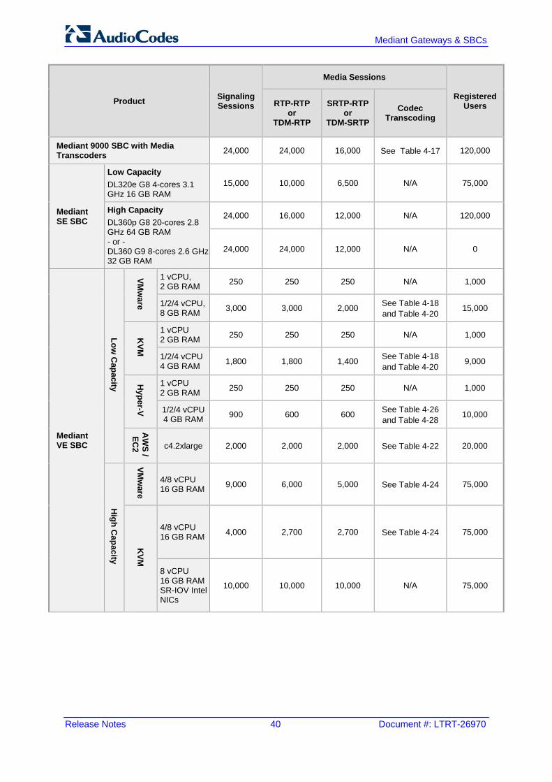
Release Notes 40 Document #: LTRT-26970
Mediant Gateways & SBCs
Product Signaling Sessions
Media Sessions
Registered Users RTP-RTP
or TDM-RTP
SRTP-RTP or
TDM-SRTP Codec
Transcoding
Mediant 9000 SBC with Media Transcoders 24,000 24,000 16,000 See Table 4-17 120,000
Mediant SE SBC
Low Capacity DL320e G8 4-cores 3.1 GHz 16 GB RAM
15,000 10,000 6,500 N/A 75,000
High Capacity DL360p G8 20-cores 2.8 GHz 64 GB RAM - or - DL360 G9 8-cores 2.6 GHz 32 GB RAM
24,000 16,000 12,000 N/A 120,000
24,000 24,000 12,000 N/A 0
Mediant VE SBC
Low C
apacity
VMw
are
1 vCPU, 2 GB RAM 250 250 250 N/A 1,000
1/2/4 vCPU, 8 GB RAM 3,000 3,000 2,000 See Table 4-18
and Table 4-20 15,000
KVM
1 vCPU 2 GB RAM 250 250 250 N/A 1,000
1/2/4 vCPU 4 GB RAM 1,800 1,800 1,400 See Table 4-18
and Table 4-20 9,000
Hyper-V
1 vCPU 2 GB RAM 250 250 250 N/A 1,000
1/2/4 vCPU 4 GB RAM 900 600 600 See Table 4-26
and Table 4-28 10,000
AW
S / EC
2 c4.2xlarge 2,000 2,000 2,000 See Table 4-22 20,000 H
igh Capacity
VMw
are
4/8 vCPU 16 GB RAM 9,000 6,000 5,000 See Table 4-24 75,000
KVM
4/8 vCPU 16 GB RAM 4,000 2,700 2,700 See Table 4-24 75,000
8 vCPU 16 GB RAM SR-IOV Intel NICs
10,000 10,000 10,000 N/A 75,000

Version 7.2 41 Mediant Gateways & SBCs
Release Notes 4. Session Capacity
Notes:
• The figures listed in the table are accurate at the time of publication of this document. However, these figures may change due to a later software update. For the latest figures, please contact your AudioCodes sales representative.
• Registered Users is the maximum number of users that can be registered with the device. This applies to the supported application (SBC or CRP).
• Regarding signaling, media, and transcoding session resources: √ A signaling session is a SIP dialog session between two SIP entities, traversing
the SBC and using one signaling session resource. √ A media session is an audio (RTP or SRTP), fax (T.38), or video session
between two SIP entities, traversing the SBC and using one media session resource.
√ A gateway session (i.e. TDM-RTP or TDM-SRTP) is also considered as a media session for the calculation of media sessions. In other words, the maximum Media Sessions specified in the table refer to the sum of Gateway and SBC sessions.
√ In case of direct media (i.e., Anti-tromboning / Non-Media Anchoring), where only SIP signaling traverses the SBC and media flows directly between the SIP entities, only a signaling session resource is used. Thus, for products with a greater signaling session capacity than media, even when media session resources have been exhausted, additional signaling sessions can still be handled for direct-media calls.
√ For call sessions requiring transcoding, one transcoding session resource is also used. For example, for a non-direct media call in which one leg uses G.711 and the other leg G.729, one signaling resource, one media session resource, and one transcoding session resource is used.
• For Mediant 9000 SBC with Media Transcoders, each transcoding session is weighted as two RTP-RTP sessions without transcoding. Therefore, the number of sessions without transcoding plus the doubled number of sessions with transcoding must be less than the maximum RTP-RTP figure specified in the table. As result, if all sessions are with transcoding, the maximum number of sessions is half the maximum RTP-RTP sessions without transcoding specified in the table.

Release Notes 42 Document #: LTRT-26970
Mediant Gateways & SBCs
4.2 Mediant 500 E-SBC The SBC session capacity and DSP channel capacity for Mediant 500 E-SBC are shown in the tables below.
Table 4-2: Mediant 500 E-SBC (Non Hybrid) SBC Capacity
Hardware Configuration
TDM-RTP Sessions RTP-RTP Sessions
DSP Channels Allocated for PSTN
Wideband Coders Max. SBC Sessions
G.722 AMR-WB SILK-WB
SBC N/A N/A N/A N/A 250
Table 4-3: Mediant 500 Hybrid E-SBC (with Gateway) Media & SBC Capacity
Hardware Configuration
TDM-RTP Sessions RTP-RTP Sessions
DSP Channels Allocated for PSTN
Wideband Coders Max. SBC Sessions
G.722 AMR-WB SILK-WB
1 x E1/T1
30/24 √ - - 220/226 26/24 √ √ - 224/226
26/24 √ √ √ 226/226
4.3 Mediant 500L Gateway and E-SBC The SBC session capacity and DSP channel capacity for Mediant 500L Gateway and E-SBC is shown in the tables below.
Table 4-4: Mediant 500L E-SBC (Non Hybrid) SBC Capacity
Hardware Configuration
TDM-RTP Sessions RTP-RTP Sessions
DSP Channels Allocated for PSTN
Wideband Coders Max. SBC Sessions G.722 AMR-WB
SBC N/A N/A N/A 60
Table 4-5: Mediant 500L Hybrid E-SBC (with Gateway) Media & SBC Capacity
Hardware Configuration
DSP Channels Allocated for PSTN
Additional Coders
Max. SBC Sessions
Narrowband Wideband
Opus-NB G.722 AMR-WB Opus-WB
2 x BRI / 4 x BRI
4/8 - - - - 56/52 4/8 - √ - - 56/52 4/6 √ - √ - 56/54 4 - - - √ 56

Version 7.2 43 Mediant Gateways & SBCs
Release Notes 4. Session Capacity
4.4 Mediant 800/B Gateway & E-SBC The DSP channel capacity and SBC session capacity for Mediant 800 Gateway & E-SBC and Mediant 800B Gateway & E-SBC are shown in the tables below.
Table 4-6: Mediant 800/B Gateway & E-SBC SBC Session Capacity per Capabilities (SBC Only)
H/W Configuration
DSP Channels for
PSTN
SBC Transcoding Sessions Max. SBC Sessions
From Profile 2 with Additional Advanced DSP Capabilities To
Profile 1 To
Profile 2
Mediant
800 Mediant
800B
Opus-NB Opus-WB AMR-NB / G.722 AMR-WB SILK-NB
/ iLBC SILK-WB
SBC
N/A - - - - - - 57 48 60 250 N/A - - √ - - - 51 42 60 250 N/A - - - - √ - 39 33 60 250 N/A - - - √ - - 36 30 60 250 N/A - - - - - √ 27 24 60 250 N/A √ - - - - - 27 24 60 250 N/A - √ - - - - 21 21 60 250
Table 4-7: Mediant 800/B Gateway & E-SBC Channel Capacity per Capabilities (with Gateway)
Telephony Interface
Assembly
DSP Channels Allocated for PSTN
SBC Transcoding Sessions
Conf.
Participants
Max. SBC Sessions
From Profile 2 with Additional Advanced DSP Capabilities To
Profile 1 To
Profile 2
Mediant 800
Mediant 800B
AMR-
NB / G.722
AMR-WB
SILK-NB
SILK-WB
Opus-NB
Opus-WB V.150.1
2 x E1/T1 60/48 - - - - - - - 3/15 2/13 - 0/12 190/202 2 x T1 48 - - - - - - √ 11 9 - 12 202 1 x E1/T1 & 8 x FXS/FXO Mix
38/32 - - - - - - - 22/28 18/22 - 22/28 212/218 38/32 - - √ - - - - 8/12 7/11 - 22/28 212/218
1 x E1/T1 30/24 - - √ - - √ 14/18 12/16 - 30/36 220/226 1 x E1 & 4 x BRI
38 - - - - - - - 22 18 - 22 215
1 x E1 & 4 x FXS
34 - - - - - - - 26 21 - 26 216
2 x E1 & 4 x FXS
64 - - - - - - - 0 0 - 0 186
4 x BRI & 4 x FXS & 4 x FXO
16 - - - - - - - 5 4 - 44 234

Release Notes 44 Document #: LTRT-26970
Mediant Gateways & SBCs
Telephony Interface
Assembly
DSP Channels Allocated for PSTN
SBC Transcoding Sessions
Conf.
Participants
Max. SBC Sessions
From Profile 2 with Additional Advanced DSP Capabilities To
Profile 1 To
Profile 2
Mediant 800
Mediant 800B
AMR-
NB / G.722
AMR-WB
SILK-NB
SILK-WB
Opus-NB
Opus-WB V.150.1
8 x BRI & 4 x FXS
20 - - - - - - - 1 1 - 40 230
8 x BRI 16 - - - - - - - 5 4 - 44 234 12 x FXS 12 - - √ - - - √ 3 3 - 48 238 4 x FXS & 8 x FXO 12 - - √ - - - - 3 3 - 48 238 8 x FXS & 4 x FXO 12 - - √ - - - - 3 3 - 48 238
4 x BRI & 4 x FXS 12 - - √ - - - - 3 3 - 48 238
4 x FXS & 4 x FXO
8 - - - - - - - 7 5 6 52 242 8 - - √ - - - - 6 6 - 52 242
4 x BRI 8 - - - - - - - 7 5 6 52 242 8 - - √ - - - - 6 6 - 52 242
1/2/3 x BRI 2/4/6 - - - - - - - 17/15/
14 14/13/11 - 58/56/54 248/246/244
2/4/6 - - √ - - - - 11/10/8 10/8/7 - 58/56/54 248/246/2
44
4 x FXS or 4 x FXO
4 - - √ - - - √ 10 8 - 56 246 4 √ - - - - - - 12 10 4 56 246 4 - - √ - - - - 6 6 4 56 246 4 - √ √ - - - - 4 4 4 56 246 4 - √ √ √ - - - 3 3 4 56 246
4 - - - - √ - - 1 0 4 56 246
4 - - - - - √ - 0 0 3 56 246
FXS, FXO, and/or BRI, but not in use
0 - - - - - - - 19 16 - 60 250

Version 7.2 45 Mediant Gateways & SBCs
Release Notes 4. Session Capacity
Notes:
• Profile 1: G.711 at 20ms only, with In-band signaling (in voice channel) and Silence Suppression (no fax detection or T.38 support).
• Profile 2: G.711, G.726, G.729, and G.723.1, T.38 with fax detection, In-band signaling (in voice channel), and Silence Compression.
• All hardware assemblies also support the following DSP channel capabilities: echo cancellation (EC), CID (caller ID), RTCP XR reporting, and SRTP.
• SBC enhancements (e.g. Acoustic Echo Suppressor, Noise Reduction) are also available for these configurations. For more information, please contact your AudioCodes sales representative.
• Automatic Gain Control (AGC) and Answer Detector / Answer Machine Detector (AD/AMD) are also available for these configurations. For more information, please contact your AudioCodes sales representative.
• V.150.1 is supported only for the US Department of Defense (DoD). • Transcoding Sessions represents part of the total SBC sessions. • Conference Participants represents the number of concurrent analog ports in a three-
way conference call. • For availability of the telephony assemblies listed in the table above, please contact
your AudioCodes sales representative.

Release Notes 46 Document #: LTRT-26970
Mediant Gateways & SBCs
4.5 Mediant 1000B Gateway & E-SBC This section lists the channel capacity and DSP templates for Mediant 1000B Gateway & E-SBC DSP.
Notes:
• The maximum number of channels on any form of analog, digital, and MPM module assembly is 192. When the device handles both SBC and Gateway call sessions, the maximum number of total sessions is 150. When the device handles SRTP, the maximum capacity is reduced to 120.
• Installation and use of voice coders is subject to obtaining the appropriate license and royalty payments.
• For additional DSP templates, contact your AudioCodes sales representative.
4.5.1 Analog (FXS/FXO) Interfaces The channel capacity per DSP firmware template for analog interfaces is shown in the table below.
Table 4-8: Channel Capacity per DSP Firmware Template for Mediant 1000B Analog Series
DSP Template
0, 1, 2, 4, 5, 6 10, 11, 12, 14, 15, 16
Number of Channels
4 3
Voice Coder
G.711 A/Mu-law PCM √ √
G.726 ADPCM √ √
G.723.1 √ √
G.729 A, B √ √
G.722 - √

Version 7.2 47 Mediant Gateways & SBCs
Release Notes 4. Session Capacity
4.5.2 BRI Interfaces The channel capacity per DSP firmware template for BRI interfaces is shown in the table below.
Table 4-9: Channel Capacity per DSP Firmware Template for Mediant 1000B BRI Series
DSP Template
0, 1, 2, 4, 5, 6 10, 11, 12, 14, 15, 16
Number of BRI Spans
4 8 20 4 8 20
Number of Channels
8 16 40 6 12 30
Voice Coder
G.711 A/Mu-law PCM √ √
G.726 ADPCM √ √
G.723.1 √ √
G.729 A, B √ √
G.722 - √

Release Notes 48 Document #: LTRT-26970
Mediant Gateways & SBCs
4.5.3 E1/T1 Interfaces The channel capacity per DSP firmware template for E1/T1 interfaces is shown in the table below.
Table 4-10: Channel Capacity per DSP Firmware Templates for Mediant 1000B E1/T1 Series
DSP Template
0 or 10 1 or 11 2 or 12 5 or 15 6 or 16
Number of Spans
1 2 4 8 1 2 4 8 1 2 4 8 1 2 4 8 1 2 4 8
Number of Channels
Default Settings 31 62 120 192 31 48 80 160 24 36 60 120 24 36 60 120 31 60 100 192
With 128 ms EC 31 60 100 192 31 48 80 160 24 36 60 120 24 36 60 120 31 60 100 192
With IPM Features Automatic Gain Control (AGC), Answer Machine
Detection (AMD) and Answer Detection (AD)
31 60 100 192 - - - - - - - - - - - - 31 60 100 192
Voice Coder
G.711 A-law/Mµ-law PCM
G.726 ADPCM -
G.723.1 - - - -
G.729 A, B
GSM FR - - -
MS GSM - - -
iLBC - - - -
EVRC - - - -
QCELP - - - -
AMR - - - -
GSM EFR - - - -
G.722 - - - -
Transparent

Version 7.2 49 Mediant Gateways & SBCs
Release Notes 4. Session Capacity
4.5.4 Media Processing Interfaces The channel capacity per DSP firmware template for media processing (provided by the MPM module) is shown in the table below.
Notes:
• The device can be housed with up to four MPM modules. • The MPM modules can only be housed in slots 1 through 5.
Table 4-11: Channel Capacity per DSP Firmware Template for Mediant 1000B MPM Series
DSP Template
0 or 10 1 or 11 2 or 12 5 or 15 6 or 16
IPM Detectors Automatic Gain Control (AGC),
Answer Machine Detection (AMD) and Answer Detection (AD)
Number of Transcoding Sessions per MPM Module
- 24 16 12 12 20
20 - - - 20
Voice Coder
G.711 A-law / Mµ-law PCM
G.726 ADPCM -
G.723.1 - - - -
G.729 A, B
GSM FR - - -
MS GSM - - -
iLBC - - - -
EVRC - - - -
QCELP - - - -
AMR - - - -
GSM EFR - - - -
G.722 - - - -
Transparent

Release Notes 50 Document #: LTRT-26970
Mediant Gateways & SBCs
4.6 Mediant 2600 E-SBC The maximum number of supported SBC sessions is shown in Section 4.1 on page 39. These SBC sessions also support SRTP and RTCP XR. When DSP capabilities are required, the number of sessions that can use DSP capabilities is reduced, as shown in the table below:
Table 4-12: Channel Capacity per Coder-Capability Profile for Mediant 2600 E-SBC
Session Coders Max. Sessions
From Coder Profile To Coder Without MPM4 With MPM4
1 Profile 1 400 600
2 Profile 1 300 600
2 Profile 2 250 600
1 Profile 2 + AMR-NB / G.722 275 600
2 Profile 2 + AMR-NB / G.722 225 600
1 Profile 2 + iLBC 175 575
2 Profile 2 + iLBC 150 500
1 Profile 2 + AMR-WB 200 600
2 Profile 2 + AMR-WB 175 525
1 Profile 2 + SILK-NB 200 600
2 Profile 2 + SILK-NB 175 525
1 Profile 2 + SILK-WB 100 350
2 Profile 2 + SILK-WB 100 350
1 Profile 2 + Opus-NB 125 425
2 Profile 2 + Opus-NB 125 375
1 Profile 2 + Opus-WB 100 300
2 Profile 2 + Opus-WB 75 275
Notes:
• Profile 1: G.711 at 20ms only, with in-band signaling (in voice channel) and Silence Suppression (no fax detection or T.38 support).
• Profile 2: G.711, G.726, G.729, G.723.1, T.38 with fax detection, in-band signaling (in voice channel), and Silence Compression.
• Acoustic Echo Suppressor reduces performance. For more information, contact your AudioCodes sales representative.
• MPM is the optional, Media Processing Module that provides additional DSPs, allowing greater capacity.

Version 7.2 51 Mediant Gateways & SBCs
Release Notes 4. Session Capacity
4.7 Mediant 4000 SBC The maximum number of supported SBC sessions is listed in Section 4.1 on page 39. These SBC sessions also support SRTP and RTCP XR. When DSP capabilities are required, the number of sessions that can use DSP capabilities is reduced, as shown in the table below.
Table 4-13: Channel Capacity per Coder-Capability Profile for Mediant 4000 SBC
Session Coders Max. Sessions
From Coder Profile To Coder Without MPM8 With MPM8
1 Profile 1 800 2,400
2 Profile 1 600 1,850
2 Profile 2 500 1,550
1 Profile 2 + AMR-NB / G.722 550 1,650
2 Profile 2 + AMR-NB / G.722 450 1,350
1 Profile 2 + iLBC 350 1,150
2 Profile 2 + iLBC 300 1,000
1 Profile 2 + AMR-WB 400 1,200
2 Profile 2 + AMR-WB 350 1,050
1 Profile 2 + SILK-NB 400 1,200
2 Profile 2 + SILK-NB 350 1,050
1 Profile 2 + SILK-WB 200 700
2 Profile 2 + SILK-WB 200 700
1 Profile 2 + Opus-NB 250 850
2 Profile 2 + Opus-NB 250 750
1 Profile 2 + Opus-WB 200 600
2 Profile 2 + Opus-WB 150 550
Notes:
• Profile 1: G.711 at 20ms only, with in-band signaling (in voice channel) and Silence Suppression (no fax detection or T.38 support).
• Profile 2: G.711, G.726, G.729, G.723.1, T.38 with fax detection, in-band signaling (in voice channel), and Silence Compression.
• Acoustic Echo Suppressor reduces performance. For more information, contact your AudioCodes sales representative.
• MPM is the optional, Media Processing Module that provides additional DSPs, allowing greater capacity.
The device can handle up to 5,000 fax detections, answer detections (AD), answering machine detections (AMD), beep detections, and Call Progress Tone detections, with the following assumptions: Timeout for fax detection is 10 seconds (default), after which fax detection is turned off
and the call is resumed without the fax detector.

Release Notes 52 Document #: LTRT-26970
Mediant Gateways & SBCs
Fax detection is applied on both legs of the SBC call. Minimum call duration is 100 seconds. AD, AMD, beep detection, and Call Progress Tone detection is only on one leg of the
SBC call (should this not be the case, capacity figures will be reduced)

Version 7.2 53 Mediant Gateways & SBCs
Release Notes 4. Session Capacity
4.8 Mediant 4000B SBC The maximum number of supported SBC sessions is listed in Section 4.1 on page 39. These SBC sessions also support SRTP and RTCP XR. When DSP capabilities are required, the number of sessions that can use DSP capabilities is reduced, as shown in the table below.
Table 4-14: Channel Capacity per Coder-Capability Profile for Mediant 4000B SBC
Session Coders Number of Sessions From Coder Profile
To Coder Without MPM
1 x MPM8B
1 x MPM12B
2 x MPM12B
3 x MPM12B
1 Profile 1 800 2,400 3,250 5,000 5,000 2 Profile 1 600 1,850 2,450 4,350 5,000 2 Profile 2 500 1,550 2,100 3,650 5,000 1 Profile 2 + AMR-NB / G.722 550 1,650 2,200 3,850 5,000 2 Profile 2 + AMR-NB / G.722 450 1,350 1,800 3,150 4,550 1 Profile 2 + iLBC 400 1,200 1,600 2,850 4,050 2 Profile 2 + iLBC 350 1,050 1,400 2,500 3,600 1 Profile 2 + AMR-WB 400 1,200 1,600 2,850 4,050 2 Profile 2 + AMR-WB 350 1,050 1,400 2,500 3,600 1 Profile 2 + SILK-NB 400 1,200 1,600 2,850 4,050 2 Profile 2 + SILK-NB 350 1,050 1,400 2,500 3,600 1 Profile 2 + SILK-WB 200 700 950 1,650 2,400 2 Profile 2 + SILK-WB 200 700 950 1,650 2,400 1 Profile 2 + Opus-NB 250 850 1,150 2,000 2,850 2 Profile 2 + Opus-NB 250 750 1,050 1,800 2,600 1 Profile 2 + Opus-WB 200 600 850 1,500 2,150 2 Profile 2 + Opus-WB 150 550 750 1,300 1,900
Notes:
• Profile 1: G.711 at 20ms only, with In-band signaling (in voice channel) and Silence Suppression (no fax detection or T.38 support).
• Profile 2: G.711, G.726, G.729, G.723.1, AMR-NB, T.38 with fax detection, In-band signaling (in voice channel), and Silence Compression.
• Acoustic Echo Suppressor reduces performance by about 30%. For more information, contact your AudioCodes sales representative.
• MPMB is the optional, Media Processing Module that provides additional DSPs, allowing greater capacity.

Release Notes 54 Document #: LTRT-26970
Mediant Gateways & SBCs
The device can handle up to 5,000 fax detections, answer detections (AD), answering machine detections (AMD), beep detections, and Call Progress Tone detections, with the following assumptions: Timeout for fax detection is 10 seconds (default), after which fax detection is turned off
and the call is resumed without the fax detector. Fax detection is applied on both legs of the SBC call. Minimum call duration is 100 seconds. AD, AMD, beep detection, and Call Progress Tone detection is only on one leg of the
SBC call (should this not be the case, capacity figures will be reduced)

Version 7.2 55 Mediant Gateways & SBCs
Release Notes 4. Session Capacity
4.9 Mediant 9000 SBC The maximum number of supported SBC sessions is listed in Section 4.1 on page 39. These SBC sessions also support SRTP and RTCP XR. When DSP capabilities are required, the number of sessions that can use DSP capabilities is reduced, as shown in the table below.
Table 4-15: Channel Capacity per Coder-Capability Profile for Mediant 9000 SBC
Session Coders Number of Sessions
From Coder Profile To Coder Extended Basic
1 Profile 1 2,000 2,550 2 Profile 1 975 1,300 2 Profile 2 650 875 1 Profile 2 + AMR-NB / G.722 875 1,125 2 Profile 2 + AMR-NB / G.722 600 800 1 Profile 2 + AMR-WB 325 375 2 Profile 2 + AMR-WB 275 325 1 Profile 2 + SILK-NB 750 1,050 2 Profile 2 + SILK-NB 550 750 1 Profile 2 + SILK-WB 500 600 2 Profile 2 + SILK-WB 400 500 1 Profile 2 + Opus-NB 600 850 2 Profile 2 + Opus-NB 450 650 1 Profile 2 + Opus-WB 400 525 2 Profile 2 + Opus-WB 350 425
Notes:
• Profile 1: G.711 at 20ms only, without T.38 support. • Profile 2: G.711, G.726, G.729, G.723.1, T.38. • Basic: excludes in-band signaling (in voice channel), VAD, Silence Suppression and
fax detection. • Extended: includes in-band signaling (in voice channel), VAD, Silence Suppression
and fax detection • Acoustic Echo Suppressor may reduce capacity. For more information, contact your
AudioCodes sales representative.
The table below lists the maximum number of concurrent sessions per detection feature. The figures are based on the following assumptions: Timeout for fax detection is 10 seconds (default) Call duration is 100 seconds Fax detection is required on both legs of the SBC call

Release Notes 56 Document #: LTRT-26970
Mediant Gateways & SBCs
Answer Detection (AD), Answering Machine Detection (AMD), Beep Detection, and Call Progress Tone Detection (CP) is only on one leg of the SBC call (should this not be the case, figures will be reduced)
Sessions are only for forwarding sessions (i.e., no transcoding)
Table 4-16: Channel Capacity per Detection Feature for Mediant 9000 SBC
Special Detection Features Number of Sessions
Fax Detection 24,000
AD/AMD/Beep Detection 24,000
CP Detection 24,000
Jitter Buffer 2,225
4.10 Mediant 9000 SBC with Media Transcoders Mediant 9000 SBC with Media Transcoders allows increasing the number of transcoding sessions by using Media Transcoders. The maximum number of supported Media Transcoders is six. The maximum number of transcoding sessions depends on the number of Media Transcoders in the media transcoding cluster and depends on the cluster operation mode (Best-Effort or Full-HA mode). The following table lists maximum transcoding sessions capacity of a single Media Transcoder.
Table 4-17: Transcoding Capacity per Profile for a Single Media Transcoder
Session Coders Number of Sessions
From Coder Profile To Coder 1 x MPM12B 2 x MPM12B 3 x MPM12B
1 Profile 1 2875 5000 5000
2 Profile 1 2300 4025 5000
2 Profile 2 1800 3175 4550
1 Profile 2 + AMR-NB / G.722 2000 3525 5000
2 Profile 2 + AMR-NB / G.722 1625 2850 4075
1 Profile 2 + AMR-WB 1425 2500 3600
2 Profile 2 + AMR-WB 1225 2175 3100
1 Profile 2 + SILK-NB 1425 2500 3600
2 Profile 2 + SILK-NB 1225 2175 3100
1 Profile 2 + SILK-WB 850 1500 2150
2 Profile 2 + SILK-WB 850 1500 2150
1 Profile 2 + Opus-NB 1050 1825 2625
2 Profile 2 + Opus-NB 950 1675 2400
1 Profile 2 + Opus-WB 750 1325 1900
2 Profile 2 + Opus-WB 650 1175 1675

Version 7.2 57 Mediant Gateways & SBCs
Release Notes 4. Session Capacity
Notes:
• Profile 1: G.711 at 20ms only, with In-band signaling (in voice channel) and Silence Suppression (no fax detection or T.38 support).
• Profile 2: G.711, G.726, G.729, G.723.1, AMR-NB, T.38 with fax detection, In-band signaling (in voice channel), and Silence Compression.
• Acoustic Echo Suppressor reduces performance by about 30%. For more information, contact your AudioCodes sales representative.
• MPM12B is a Media Processing Module in the Media Transcoder that provides additional DSPs, allowing higher capacity.
• For best cluster efficiency, all Media Transcoders in the Cluster should populate the same number of MPM12Bs.

Release Notes 58 Document #: LTRT-26970
Mediant Gateways & SBCs
4.11 Mediant Server Edition SBC
Note: Mediant Server Edition SBC does not implement digital signal processing (DSP). Therefore, it supports only SBC functionalities that do not require media signal processing.
4.12 Mediant Virtual Edition SBC The maximum number of supported SBC sessions is listed in Section 4.1 on page 39. These SBC sessions also support SRTP and RTCP XR. Low-capacity Mediant VE also supports DSP capabilities. When DSP capabilities are required, the number of sessions that can use DSP capabilities is reduced, as shown in the tables in this section.
4.12.1 Mediant VE SBC for KVM and VMware Hypervisors The following tables list maximum channel capacity for Mediant VE SBC 2.8 GHz running on KVM or VMware hypervisors.
4.12.1.1 2-vCPU Mediant VE SBC The following table lists maximum channel capacity for the 2-vCPU (1 vCPU reserved for DSP) low-capacity Mediant VE SBC.
Table 4-18: Channel Capacity for 2-vCPU Mediant VE SBC on KVM/VMware
Session Coders Number of Sessions
From Coder Profile To Coder Extended Basic
1 Profile 1 200 250
2 Profile 1 75 125
2 Profile 2 50 75
1 Profile 2 + AMR-NB / G.722 75 100
2 Profile 2 + AMR-NB / G.722 50 75
1 Profile 2 + AMR-WB 25 25
2 Profile 2 + AMR-WB 25 25
1 Profile 2 + SILK-NB 75 100
2 Profile 2 + SILK-NB 50 75
1 Profile 2 + SILK-WB 50 50
2 Profile 2 + SILK-WB 25 50
1 Profile 2 + Opus-NB 50 75
2 Profile 2 + Opus-NB 25 50
1 Profile 2 + Opus-WB 25 50
2 Profile 2 + Opus-WB 25 25

Version 7.2 59 Mediant Gateways & SBCs
Release Notes 4. Session Capacity
Notes:
• Profile 1: G.711 at 20ms only, without T.38 support. • Profile 2: G.711, G.726, G.729, G.723.1, T.38. • Basic: excludes in-band signaling (in voice channel), VAD, Silence Suppression and
fax detection. • Extended: includes in-band signaling (in voice channel), VAD, Silence Suppression
and fax detection • Acoustic Echo Suppressor may reduce capacity. For more information, contact your
AudioCodes sales representative.
The table below lists the maximum number of concurrent sessions per detection feature. The figures are based on the following assumptions: Timeout for fax detection is 10 seconds (default) Call duration is 100 seconds Fax detection is required on both legs of the SBC call Answer Detection (AD), Answering Machine Detection (AMD), Beep Detection, and
Call Progress Tone Detection (CP) is only on one leg of the SBC call (should this not be the case, figures will be reduced)
Sessions are only for forwarding sessions (i.e., no transcoding)
Table 4-19: Channel Capacity per Detection Feature for 2-vCPU Mediant VE SBC on KVM/VMware
Special Detection Features Number of Sessions
Fax Detection 2,400
AD/AMD/Beep Detection 2,400
CP Detection 2,400
Jitter Buffer 200

Release Notes 60 Document #: LTRT-26970
Mediant Gateways & SBCs
4.12.1.2 4-vCPU Mediant VE SBC The following table lists maximum channel capacity for the 4-vCPU (3 vCPUs reserved for DSP) low-capacity Mediant VE SBC.
Table 4-20: Channel Capacity for 4-vCPU Mediant VE SBC on KVM/VMware
Session Coders Number of Sessions
From Coder Profile To Coder Extended Basic
1 Profile 1 600 750
2 Profile 1 275 375
2 Profile 2 175 250
1 Profile 2 + AMR-NB / G.722 250 325
2 Profile 2 + AMR-NB / G.722 175 225
1 Profile 2 + AMR-WB 100 100
2 Profile 2 + AMR-WB 75 75
1 Profile 2 + SILK-NB 225 300
2 Profile 2 + SILK-NB 150 225
1 Profile 2 + SILK-WB 150 175
2 Profile 2 + SILK-WB 100 150
1 Profile 2 + Opus-NB 175 250
2 Profile 2 + Opus-NB 125 175
1 Profile 2 + Opus-WB 125 150
2 Profile 2 + Opus-WB 100 125
Notes:
• Profile 1: G.711 at 20ms only, without T.38 support. • Profile 2: G.711, G.726, G.729, G.723.1, T.38. • Basic: excludes in-band signaling (in voice channel), VAD, Silence Suppression and
fax detection. • Extended: includes in-band signaling (in voice channel), VAD, Silence Suppression
and fax detection • Acoustic Echo Suppressor may reduce capacity. For more information, contact your
AudioCodes sales representative.

Version 7.2 61 Mediant Gateways & SBCs
Release Notes 4. Session Capacity
The table below lists the maximum number of concurrent sessions per detection feature. The figures are based on the following assumptions: Timeout for fax detection is 10 seconds (default) Call duration is 100 seconds Fax detection is required on both legs of the SBC call Answer Detection (AD), Answering Machine Detection (AMD), Beep Detection, and
Call Progress Tone Detection (CP) is only on one leg of the SBC call (should this not be the case, figures will be reduced)
Sessions are only for forwarding sessions (i.e., no transcoding)
Table 4-21: Channel Capacity per Detection Feature for 4-vCPU Mediant VE SBC on KVM/VMware
Special Detection Features Number of Sessions
Fax Detection 7,200
AD/AMD/Beep Detection 7,200
CP Detection 7,200
Jitter Buffer 650
4.12.1.3 Amazon AWS EC2 The following table lists maximum channel capacity for low-capacity Mediant VE SBC on the Amazon EC2 platform.
Table 4-22: Channel Capacity for Mediant VE SBC on Amazon EC2
Session Coders Number of Sessions
From Coder Profile To Coder Extended Basic
1 Profile 1 600 750
2 Profile 1 275 375
2 Profile 2 175 250
1 Profile 2 + AMR-NB / G.722 250 325
2 Profile 2 + AMR-NB / G.722 175 225
1 Profile 2 + AMR-WB 100 100
2 Profile 2 + AMR-WB 75 75
1 Profile 2 + SILK-NB 225 300
2 Profile 2 + SILK-NB 150 225
1 Profile 2 + SILK-WB 150 175
2 Profile 2 + SILK-WB 100 150
1 Profile 2 + Opus-NB 175 250
2 Profile 2 + Opus-NB 125 175
1 Profile 2 + Opus-WB 125 150
2 Profile 2 + Opus-WB 100 125
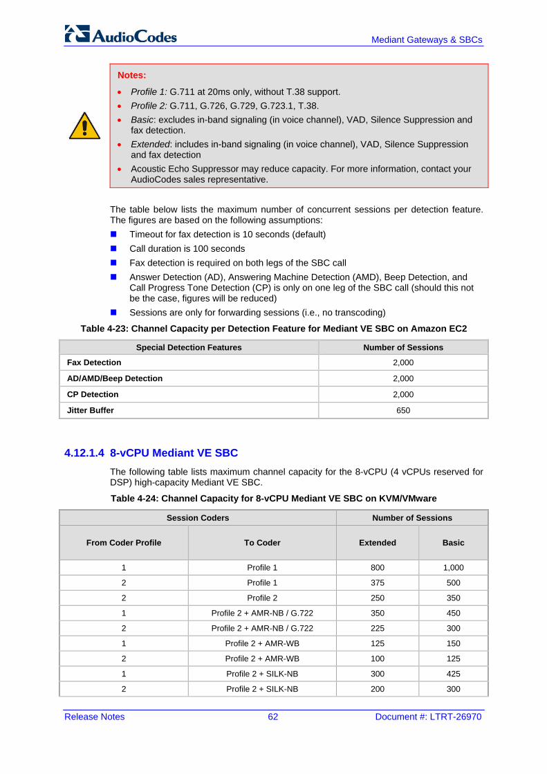
Release Notes 62 Document #: LTRT-26970
Mediant Gateways & SBCs
Notes:
• Profile 1: G.711 at 20ms only, without T.38 support. • Profile 2: G.711, G.726, G.729, G.723.1, T.38. • Basic: excludes in-band signaling (in voice channel), VAD, Silence Suppression and
fax detection. • Extended: includes in-band signaling (in voice channel), VAD, Silence Suppression
and fax detection • Acoustic Echo Suppressor may reduce capacity. For more information, contact your
AudioCodes sales representative.
The table below lists the maximum number of concurrent sessions per detection feature. The figures are based on the following assumptions: Timeout for fax detection is 10 seconds (default) Call duration is 100 seconds Fax detection is required on both legs of the SBC call Answer Detection (AD), Answering Machine Detection (AMD), Beep Detection, and
Call Progress Tone Detection (CP) is only on one leg of the SBC call (should this not be the case, figures will be reduced)
Sessions are only for forwarding sessions (i.e., no transcoding)
Table 4-23: Channel Capacity per Detection Feature for Mediant VE SBC on Amazon EC2
Special Detection Features Number of Sessions
Fax Detection 2,000
AD/AMD/Beep Detection 2,000
CP Detection 2,000
Jitter Buffer 650
4.12.1.4 8-vCPU Mediant VE SBC The following table lists maximum channel capacity for the 8-vCPU (4 vCPUs reserved for DSP) high-capacity Mediant VE SBC.
Table 4-24: Channel Capacity for 8-vCPU Mediant VE SBC on KVM/VMware
Session Coders Number of Sessions
From Coder Profile To Coder Extended Basic
1 Profile 1 800 1,000
2 Profile 1 375 500
2 Profile 2 250 350
1 Profile 2 + AMR-NB / G.722 350 450
2 Profile 2 + AMR-NB / G.722 225 300
1 Profile 2 + AMR-WB 125 150
2 Profile 2 + AMR-WB 100 125
1 Profile 2 + SILK-NB 300 425
2 Profile 2 + SILK-NB 200 300

Version 7.2 63 Mediant Gateways & SBCs
Release Notes 4. Session Capacity
Session Coders Number of Sessions
From Coder Profile To Coder Extended Basic
1 Profile 2 + SILK-WB 200 225
2 Profile 2 + SILK-WB 150 200
1 Profile 2 + Opus-NB 225 325
2 Profile 2 + Opus-NB 175 250
1 Profile 2 + Opus-WB 150 200
2 Profile 2 + Opus-WB 125 175
Notes:
• Profile 1: G.711 at 20ms only, without T.38 support. • Profile 2: G.711, G.726, G.729, G.723.1, T.38. • Basic: excludes in-band signaling (in voice channel), VAD, Silence Suppression and
fax detection. • Extended: includes in-band signaling (in voice channel), VAD, Silence Suppression
and fax detection • Acoustic Echo Suppressor may reduce capacity. For more information, contact your
AudioCodes sales representative.
The table below lists the maximum number of concurrent sessions per detection feature. The figures are based on the following assumptions: Timeout for fax detection is 10 seconds (default) Call duration is 100 seconds Fax detection is required on both legs of the SBC call Answer Detection (AD), Answering Machine Detection (AMD), Beep Detection, and
Call Progress Tone Detection (CP) is only on one leg of the SBC call (should this not be the case, figures will be reduced)
Sessions are only for forwarding sessions (i.e., no transcoding)
Table 4-25: Channel Capacity per Detection Feature for 8-vCPU Mediant VE SBC on KVM/VMware
Special Detection Features Number of Sessions
Fax Detection 9,600
AD/AMD/Beep Detection 9,600
CP Detection 9,600
Jitter Buffer 875

Release Notes 64 Document #: LTRT-26970
Mediant Gateways & SBCs
4.12.2 Mediant VE SBC for Hyper-V Hypervisor The following tables lists maximum channel capacity for Mediant VE SBC 2.1 GHz running on Hyper-V hypervisor.
4.12.2.1 2-vCPU Mediant VE SBC The following table lists maximum channel capacity for the 2-vCPU (1 vCPU reserved for DSP) low-capacity Mediant VE SBC.
Table 4-26: Channel Capacity for 2-vCPU Mediant VE SBC on Hyper-V
Session Coders Number of Sessions
From Coder Profile To Coder Extended Basic
1 Profile 1 150 175
2 Profile 1 50 75
2 Profile 2 25 50
1 Profile 2 + AMR-NB / G.722 50 75
2 Profile 2 + AMR-NB / G.722 25 50
1 Profile 2 + AMR-WB 25 25
2 Profile 2 + AMR-WB 0 25
1 Profile 2 + SILK-NB 50 75
2 Profile 2 + SILK-NB 25 50
1 Profile 2 + SILK-WB 25 25
2 Profile 2 + SILK-WB 25 25
1 Profile 2 + Opus-NB 25 50
2 Profile 2 + Opus-NB 25 25
1 Profile 2 + Opus-WB 25 25
2 Profile 2 + Opus-WB 25 25
Notes:
• Profile 1: G.711 at 20ms only, without T.38 support. • Profile 2: G.711, G.726, G.729, G.723.1, T.38. • Basic: excludes in-band signaling (in voice channel), VAD, Silence Suppression and
fax detection. • Extended: includes in-band signaling (in voice channel), VAD, Silence Suppression
and fax detection • Acoustic Echo Suppressor may reduce capacity. For more information, contact your
AudioCodes sales representative.

Version 7.2 65 Mediant Gateways & SBCs
Release Notes 4. Session Capacity
The table below lists the maximum number of concurrent sessions per detection feature. The figures are based on the following assumptions: Timeout for fax detection is 10 seconds (default) Call duration is 100 seconds Fax detection is required on both legs of the SBC call Answer Detection (AD), Answering Machine Detection (AMD), Beep Detection, and
Call Progress Tone Detection (CP) is only on one leg of the SBC call (should this not be the case, figures will be reduced)
Sessions are only for forwarding sessions (i.e., no transcoding)
Table 4-27: Channel Capacity per Detection Feature for 2-vCPU Mediant VE SBC on Hyper-V
Special Detection Features Number of Sessions
Fax Detection 1,800
AD/AMD/Beep Detection 1,800
CP Detection 1,800
Jitter Buffer 150
4.12.2.2 4-vCPU Mediant VE SBC The following table lists maximum channel capacity for the 4-vCPU (3 vCPUs reserved for DSP) low-capacity Mediant VE SBC.
Table 4-28: Channel Capacity for 4-vCPU Mediant VE SBC on Hyper-V
Session Coders Number of Sessions
From Coder Profile To Coder Extended Basic
1 Profile 1 450 550
2 Profile 1 200 275
2 Profile 2 125 175
1 Profile 2 + AMR-NB / G.722 175 250
2 Profile 2 + AMR-NB / G.722 125 175
1 Profile 2 + AMR-WB 75 75
2 Profile 2 + AMR-WB 50 75
1 Profile 2 + SILK-NB 150 225
2 Profile 2 + SILK-NB 100 150
1 Profile 2 + SILK-WB 100 125
2 Profile 2 + SILK-WB 75 100
1 Profile 2 + Opus-NB 125 175
2 Profile 2 + Opus-NB 100 125
1 Profile 2 + Opus-WB 75 100
2 Profile 2 + Opus-WB 75 75

Release Notes 66 Document #: LTRT-26970
Mediant Gateways & SBCs
Notes:
• Profile 1: G.711 at 20ms only, without T.38 support. • Profile 2: G.711, G.726, G.729, G.723.1, T.38. • Basic: excludes in-band signaling (in voice channel), VAD, Silence Suppression and
fax detection. • Extended: includes in-band signaling (in voice channel), VAD, Silence Suppression
and fax detection • Acoustic Echo Suppressor may reduce capacity. For more information, contact your
AudioCodes sales representative.
The table below lists the maximum number of concurrent sessions per detection feature. The figures are based on the following assumptions: Timeout for fax detection is 10 seconds (default) Call duration is 100 seconds Fax detection is required on both legs of the SBC call Answer Detection (AD), Answering Machine Detection (AMD), Beep Detection, and
Call Progress Tone Detection (CP) is only on one leg of the SBC call (should this not be the case, figures will be reduced)
Sessions are only for forwarding sessions (i.e., no transcoding)
Table 4-29: Channel Capacity per Detection Feature for 4-vCPU Mediant VE SBC on Hyper-V
Special Detection Features Number of Sessions
Fax Detection 5,400
AD/AMD/Beep Detection 5,400
CP Detection 5,400
Jitter Buffer 500

Version 7.2 67 Mediant Gateways & SBCs
Release Notes 5. Obsolete Features and Parameters
5 Obsolete Features and Parameters This chapter lists obsolete features and parameters.
5.1 SAS Application From Version 7.2 (inclusive), the Stand-Alone Survivability (SAS) application is no longer supported. This application has been superseded by the Cloud Resiliency Package (CRP) application, which offers a more sophisticated and comprehensive solution for call survivability. Continued support for the SAS application will still be available (until further notice) to incumbent customers running Version 7.0 or earlier. For customers currently implementing the SAS application, AudioCodes recommends migrating to the SBC application due to its feature-rich benefits. As a result, the following parameters relating to the SAS application are now obsolete: ProxySet_SASIPv4SIPInterfaceName ProxySet_SASIPv6SIPInterfaceName EnableSAS SASDefaultGatewayIP SASRegistrationTime SASConnectionReuse SASEnableRecordRoute SASProxySet RedundantSASProxySet SASBlockUnRegUsers SASEnableContactReplace SASSurvivabilityMode SASSubscribeResponse SASEnableENUM SASBindingMode SASEmergencyNumbers SASEmergencyPrefix SASEnteringEmergencyMode SASInDialogRequestMode SASInboundManipulationMode SASRegistrationManipulation

Release Notes 68 Document #: LTRT-26970
Mediant Gateways & SBCs
5.2 Obsolete Parameters The table below summarizes parameters from the previous release that are now obsolete.
Table 5-1: Obsolete Parameters
Parameter Comments
MaxCallDuration Replaced by the new parameters, GWMaxCallDuration and SBCMaxCallDuration.
MediaEnhancementProfile table Replaced by the new parameter, QualityOfServiceRules table.
MediaEnhancementRules table Replaced by the new parameter, QualityOfServiceRules table.
IPGroup_MediaEnhancementProfile
-
HandleG711AsVBD Instead of the parameter, a Message Manipulation rule can achieve the same behavior. For example: [ MessageManipulations ] FORMAT MessageManipulations_Index = MessageManipulations_ManipulationName, MessageManipulations_ManSetID, MessageManipulations_MessageType, MessageManipulations_Condition, MessageManipulations_ActionSubject, MessageManipulations_ActionType, MessageManipulations_ActionValue, MessageManipulations_RowRole; MessageManipulations 0 = mm1, 1, invite, "body.sdp REGEX (.*m=audio[^\r\n]* 0\b[^\r\n]*(?:\r\n[^m]=[^\r\n]*)*)(.*)", body.sdp, 0, "$1+'\\a=gpmd:0 vbd=yes'+$2", 0; MessageManipulations 1 = mm2, 1, invite, "body.sdp REGEX (.*m=audio[^\r\n]* 8\b[^\r\n]*(?:\r\n[^m]=[^\r\n]*)*)(.*)", body.sdp, 0, "$1+'\\a=gpmd:8 vbd=yes'+$2", 0; [ \MessageManipulations ]

Version 7.2 69 Mediant Gateways & SBCs
Release Notes 5. Obsolete Features and Parameters
This page is intentionally left blank.

International Headquarters AudioCodes Inc. 1 Hayarden Street, 27 World’s Fair Drive, Airport City Somerset, NJ 08873 Lod 7019900, Israel Tel: +1-732-469-0880 Tel: +972-3-976-4000 Fax: +1-732-469-2298 Fax: +972-3-976-4040 Contact us: www.audiocodes.com/info Website: www.audiocodes.com
Document #: LTRT-26970