mechatronic design of an explosive ordnance disposal robot · 2018-12-18 · sensor system design....
TRANSCRIPT

MECHATRONIC DESIGN OF AN EXPLOSIVE ORDNANCE DISPOSAL ROBOT
A Thesis Submitted to the Graduate School of Engineering and Sciences of
�zmir Institute of Technology in Partial Fulfillment of the Requirements for the Degree of
MASTER OF SCIENCE
in Mechanical Engineering
by Onur TAVSEL
June 2005 IZMIR

We approve the thesis of Onur TAVSEL Date of Signature ..................................... ........................ 07 July 2005 Asst. Prof. Dr. Emin Faruk KEÇEC� Supervisor Department of Mechanical Engineering �zmir Institute of Technology ..................................... ........................ 07 July 2005 Asst. Prof. Dr. Serhan ÖZDEM�R Department of Mechanical Engineering �zmir Institute of Technology ..................................... ........................ 07 July 2005 Assoc. Prof. Dr. Salih OKUR Department of Physics �zmir Institute of Technology .............................................................. 07 July 2005 Assoc. Prof. Dr. Barı� ÖZERDEM Head of Department �zmir Institute of Technology
............................................................ Assoc. Prof Dr. Semahat ÖZDEM�R
Head of the Graduate School

ABSTRACT
This study concerns with the design of an Explosive Ordnance Disposal (EOD)
Robot which is controlled in task space and with the combined sensor system the robot
is capable of autonomous navigation. The robot is composed of 4 different gripping
apparatus attached to a 4 degree of freedom manipulator arm which is controlled in task
space and a mobile platform which provides the mobility of the EOD robot in the
operation field. Since the manipulator arm of the robot is controlled in task space apart
from the control system of current EOD robots, the explosive ordnance disposal task
which requires high precision and dexterity can be accomplished much faster and more
accurate.
In addition to improvements in the control system, a combined sensory system
named VS-GPS is designed for autonomous navigation of the EOD robot by combining
vision system, sonar system and GPS to operate in outdoor fields. In order to achieve
the most feasible sensor system, all combinations of most common five conventional
sensor systems are evaluated, and VS-GPS is found to be the most effective combined
sensor system design.
Design of the EOD robot and sensor system includes the solid modeling of the
robot using a computer program, Solidworks®, strength analysis, mathematical
modeling of manipulator arm and evaluation of conventional sensor systems for an
optimum combination of sensor systems especially for autonomous outdoor navigation
of the robot.

ÖZET
Bu ara�tırma, tutucu kolu i� uzayında kontrol edilen bir bomba imha robotu ve
bu robotun otonom yönlendirilmesini sa�layan sensör sisteminin tasarlanmasını
kapsamaktadır. Robot, bomba imha i�lemini, paletlerle çeki�i sa�lanan mobil bir
platform üzerine yerle�tirilmi�, i� uzayında kontrol edilebilen 4 serbestlik dereceli bir
tutucu kol ve bu kola takılacak 4 farklı tutma aparatları ile gerçekle�tirecektir. Robot
kolunun i� uzayında kontrolü sayesinde günümüzde kullanılan bomba imha robotlarının
kontrol sistemlerinden farklı olarak, çok daha hassas ve hızlı bir �ekilde patlayıcı
maddeye müdahale edilmesi mümkün olabilecektir.
Bu robot mekanik tasarım çalı�masına ek olarak VS-GPS olarak adlandırılan ve
görüntü, sonar ve GPS sensör ve sistemlerinin kombinasyonu ile olu�turulan bir sensör
sistemi sayesinde bomba imha robotunun arazi �artlarında konumunun saptanabilmesi
ve yönlendirilebilmesi sa�lanacaktır. Optimum özellikteki kombinasyonun sa�lanması
a�amasında, konvansiyonel sensör sistemleri incelenmi� ve en yaygın 5 sensör tipinin
tüm kombinasyonları de�erlendirilmi�tir, ve VS-GPS en verimli sensör kombinasyonu
olarak bulunmu�tur.
Bomba imha robotunun tasarlanması, robotun katı modelleme programı
(Solidworks®) ile modellenmesini, dayanım hesaplarının yapılmasını, matematik
modelinin olu�turulmasını ve kovansiyonel sensör sistemlerinin incelerenerek en uygun
kombinasyonun olu�turulması a�amalarını kapsamaktadır.

ACKNOWLEDGMENTS
In this thesis study, I had a chance to deeply deal with a robotic design, which I
have been interested most during my engineering education. During my researchs, it
was an amazing exprience to work with the unique scientist, Dr. Emin Faruk Keçeci. I
would like to thank him for his motivation and belief in me from the beginning to the
end of this study.
In addition, I want to thank to my friends and my family for their support and
presence in my life. Without any of these, this study could not be completed.
This thesis study is supported by Tubitak under the project number 104M122
(2005).

v
TABLE OF CONTENTS
LIST OF FIGURES............................................................................................... ........ viii
LIST OF TABLES........................................................................................................... ix
CHAPTER 1. INTRODUCTION.......................................................................... ........... 1
1.1.The Definition of Explosive Ordnance Disposal (EOD) ......................... 1
1.2. EOD Techniques..................................................................................... 1
1.3. Definition of EOD Robot........................................................................ 3
1.4. The Need for EOD Robot ....................................................................... 3
1.5. Application Areas ................................................................................... 4
1.6. Current EOD Robots............................................................................... 4
1.7. Some of the Conventional EOD Robots on Market ............................... 4
1.7.1. tEODor™, by “Telerob Fernhantierungstechnik mbH” ................... 5
1.7.2. Vanguard™ MK2 ROV by Allen -Vanguard Co ............................. 5
1.7.3. MK-5 EOD Robot by ESIT .............................................................. 6
1.7.4. Wheelbarrow Super-M by Remotec Inc ........................................... 7
1.7.5. Robhaz-DT2 Robot........................................................................... 8
1.7.6. BISON™ by ABP Precision (Poole) Ltd.......................................... 8
1.7.7. Common Properties of Current EOD Robots ................................... 9
1.8. The Need for Task Space Operation..................................................... 11
1.9. Introduction to Environmental Sensor System Design......................... 12
1.9.1. Navigation....................................................................................... 13
1.10. Current Conventional Sensor Systems ............................................... 15
1.10.1. Vision System............................................................................... 15
1.10.2. Laser System................................................................................. 15
1.10.3. Radar System ................................................................................ 16
1.10.4. Sonar System ................................................................................ 16
1.10.5 Global Positioning System (GPS).................................................. 17
1.11. Environmental Sensor System Related Problems............................... 18
1.11.1. Paddles .......................................................................................... 19

vi
1.11.2. Shading ......................................................................................... 19
1.11.3. Sensor Tilt..................................................................................... 19
1.11.4. Lighting......................................................................................... 20
1.11.5. Weather Conditions ...................................................................... 20
1.11.6. Slippery Terrain ............................................................................ 21
1.11.7. Vibration ....................................................................................... 21
1.11.8. Beacons......................................................................................... 21
CHAPTER 2. SYSTEM ELEMENTS............................................................................ 22
2.1. Mobile Platform.................................................................................... 22
2.1.1. Power Supply.................................................................................. 26
2.1.2. Cameras .......................................................................................... 27
2.2. Manipulator Arm .................................................................................. 28
2.2.1. Operation Principle ......................................................................... 28
2.2.2. Mechanical Properties of Manipulator Arm ................................... 29
2.3. Gripper (End Effector).......................................................................... 32
2.3.1. General Purpose Gripper with 2 Jaws............................................. 32
2.3.2. Cylindrical Material Gripper with 3 Jaws....................................... 33
2.3.3. Screwing Apparatus ........................................................................ 34
2.3.4. Cutting Apparatus ........................................................................... 34
CHAPTER 3. KINEMATIC ANALYSIS OF MANIPULATOR ARM ....................... 36
3.1. Direct Kinematic Analysis of Manipulator Arm .................................. 36
3.2. Inverse Kinematic Analysis of Manipulator Arm................................. 38
CHAPTER 4. DYNAMIC ANALYSIS OF MANIPULATOR ARM........................... 42
CHAPTER 5. TASK SPACE CONTROL OF MANIPULATOR ARM ....................... 48
CHAPTER 6. SENSOR SYSTEM DESIGN ................................................................. 50
6.1. Combined Sensory System Design....................................................... 50
CHAPTER 7. CONCLUSION ....................................................................................... 53

vii
REFERENCES ............................................................................................................... 55
APPENDIX A................................................................................................................. 57
APPENDIX B ................................................................................................................. 58

viii
LIST OF FIGURES
Figure Page
Figure 1.1. Protective suit ............................................................................................... 2
Figure 1.2. Explosive containment vessel ....................................................................... 2
Figure 1.4. tEODor™...................................................................................................... 5
Figure 1.5. Vanguard™ MK-2 ........................................................................................ 6
Figure 1.6. ESIT MK-5 ................................................................................................... 7
Figure 1.7. Wheelbarrow super M .................................................................................. 8
Figure 1.8. BISON™ EOD robot .................................................................................... 9
Figure 1.9. Natural pit filled by water on the way of the vehicle.................................. 19
Figure 1.10 Signal is interrupted because of sensor tilting in rough surfaces................ 20
Figure 1.11. Height difference in topography hinders signals to/from the beacon ......... 21
Figure 2.1. The EOD robot............................................................................................ 22
Figure 2.2. Suspension mechanism of assistant wheels ................................................ 23
Figure 2.3. Tracks and driving motors .......................................................................... 24
Figure 2.4. Stability of the EOD robot on inclined surfaces ......................................... 25
Figure 2.5. Batteries slide out for quick replacement ................................................... 26
Figure 2.6. Main view camera....................................................................................... 27
Figure 2.8. Detail camera .............................................................................................. 28
Figure 2.9. Extension capacity of the manipulator arm ................................................ 30
Figure 2.10. Load capacity zones of manipulator ........................................................... 30
Figure 2.13. Different arm configurations of EOD robot ............................................... 31
Figure 2.14. General purpose gripper with 2 jaws .......................................................... 32
Figure 2.15. Gripper with 3 jaws..................................................................................... 33
Figure 2.16. Removing the triggering mechanism of an unexploded bomb ................... 33
Figure 2.17. Screwing apparatus ..................................................................................... 34
Figure 2.18. Cutting apparatus with a circular blade ...................................................... 35
Figure 3.1. The motions of manipulator arm joints....................................................... 39
Figure 3.2. The assistant angles and distances used for kinematic analysis ................... 40

ix
LIST OF TABLES
Table Page
Table 1.1. Comparison of Conventional EOD Robots on Market................................. 11
Table 1.2. Comparison of sensor systems capability..................................................... 18
Table 1.3. Comparison of sensor systems qualifications............................................... 18
Table 3.1. Denavit-Hartenberg Parameters.................................................................... 35

1
CHAPTER 1
INTRODUCTION
1.1. The Definition of Explosive Ordnance Disposal (EOD)
The term “Explosive Ordnance Disposal (EOD)” can be defined as the detection,
identification, on-site evaluation, rendering, safe recovery, and final disposal of
unexploded explosive ordnances. It may also include an explosive ordnance which has
become hazardous by damage or deterioration. As a more general term, “Bomb
Disposal” may also be alternatively used for the concepts stated above.
1.2. EOD Techniques
Many techniques exist for the neutralization of a bomb or an explosive object
where the selection of the technique depends on several variables. The greatest variable
is the proximity of the explosive or device to people or critical facilities. Items in open
fields are handled much differently than are ones in dense population areas.
The role of the Bomb Technician is to accomplish his task as remotely as
possible. Actually laying hands on a bomb is only done in an extremely life-threatening
situation, where hazards to people and critical structures can not be stopped.
Once, the technician determines exactly what the explosive or device is, and
what state it is currently in, he will formulate a procedure to render it safe. This may
include things as simple as replacing safety features, or as difficult as using high-
powered explosive-actuated devices to shear, jam, bind, or remove parts of the items'
firing train.
Preferably, this will be accomplished remotely, but there are still circumstances
when a technician must put himself at grave risk by personally handling the bomb. The
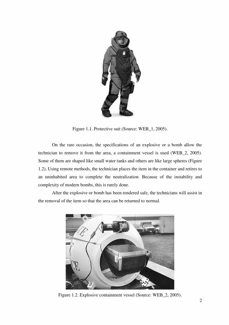
technician will often wear a specialized protective suit, consisting of flame and
fragmentation-resistant material similar to bulletproof vests. (Figure 1.1). Some suits
have advanced features such as internal cooling, amplified hearing, and communications
back to the control area (WEB_1, 2005).
2
Figure 1.1. Protective suit (Source: WEB_1, 2005).
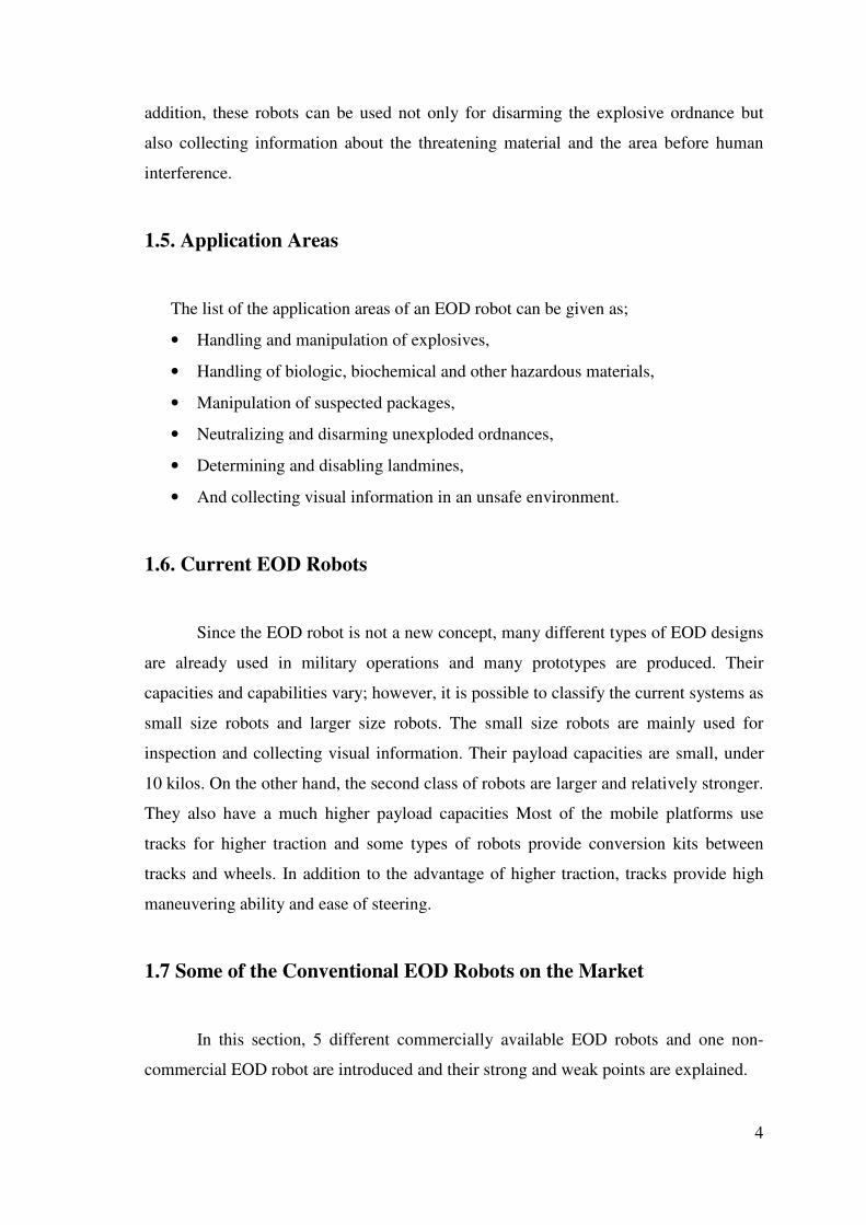
On the rare occasion, the specifications of an explosive or a bomb allow the
technician to remove it from the area, a containment vessel is used (WEB_2, 2005).
Some of them are shaped like small water tanks and others are like large spheres (Figure
1.2). Using remote methods, the technician places the item in the container and retires to
an uninhabited area to complete the neutralization. Because of the instability and
complexity of modern bombs, this is rarely done.
After the explosive or bomb has been rendered safe, the technicians will assist in
the removal of the item so that the area can be returned to normal.
Figure 1.2. Explosive containment vessel (Source: WEB_2, 2005).

3
All of these, called a mission or evolution, can take a great deal of time. Because
of the construction of devices, a wait time must be taken to ensure that whatever render-
safe method was used has worked as intended. While time is usually not on the bomb
technician's side, rushing usually ends in disaster.
The bombs or explosives usually are composed of two sections; the explosive
part which contains an explosive material and a triggering mechanism to start the
reaction which ends up with an explosion. The purpose of EOD operation is disarming
or destroying the triggering mechanism before the section containing the explosive
material is triggered.
1.3. Definition of EOD Robot
The EOD robot is a mobile robot used in replace of a human in OED operations
of searching, detecting and handling of explosive materials. The robotic system consists
of a mobile platform equipped with a serial redundant dexterous arm, a gripper and a
sensory system which provides the remote controlling abilities. Despite small
differences in order to increase versatility, current examples of EOD robots are similar
in terms of operating principles.
1.4. The Need for an EOD Robot
The development of synthetic chemicals has increased production of powerful
explosives. Most of the time, material with a doubtful origin is manipulated by specially
trained bomb squads. However, since the explosive is prepared for the highest damage,
complicated and even remotely controlled triggering mechanisms challenge a
specialist’s talents.
Today’s squads wear safety suits in case of an explosion, which minimize the
pressure of an explosion and prevent injury to a certain level (Figure1.1). On the other
hand, they limit movement capabilities and increase stress. Despite advanced safety
precautions, handling of explosive ordnances brings high risks for the operator’s life.
The basic reason and justification of the need for an EOD robot is simply the
fact that it saves human life in an explosion. The robot can be operated meters away
from the danger zone, providing a totally safe place for explosive specialists. In
4
addition, these robots can be used not only for disarming the explosive ordnance but
also collecting information about the threatening material and the area before human
interference.
1.5. Application Areas
The list of the application areas of an EOD robot can be given as;
• Handling and manipulation of explosives,
• Handling of biologic, biochemical and other hazardous materials,
• Manipulation of suspected packages,
• Neutralizing and disarming unexploded ordnances,
• Determining and disabling landmines,
• And collecting visual information in an unsafe environment.
1.6. Current EOD Robots
Since the EOD robot is not a new concept, many different types of EOD designs
are already used in military operations and many prototypes are produced. Their
capacities and capabilities vary; however, it is possible to classify the current systems as
small size robots and larger size robots. The small size robots are mainly used for
inspection and collecting visual information. Their payload capacities are small, under
10 kilos. On the other hand, the second class of robots are larger and relatively stronger.
They also have a much higher payload capacities Most of the mobile platforms use
tracks for higher traction and some types of robots provide conversion kits between
tracks and wheels. In addition to the advantage of higher traction, tracks provide high
maneuvering ability and ease of steering.
1.7 Some of the Conventional EOD Robots on the Market
In this section, 5 different commercially available EOD robots and one non-
commercial EOD robot are introduced and their strong and weak points are explained.

5
1.7.1. tEODor™, by “Telerob Fernhantierungstechnik mbH”
The tEODor 2 chain-tracked vehicle is equipped with 2 batteries at 12 volt 85
Ah each, a 6-axle power manipulator with a telescopic lower arm which has a 400-mm
telescopic zone and gripper (Figure 1.4). The visual system is composed of a separately
selectable pan tilt head as a camera mount for the main camera and two more additional
cameras for detailed view. The robot is controlled from a control console by activating
each joint separately from the control panel and controlling the motion according to the
visual information displayed on the monitor. The whole EOD operation of tEODor
depends on joint space control (WEB_3, 2004).
Figure 1.4. tEODor™ (Source: WEB_3, 2004).
1.7.2. Vanguard™ MK2 ROV by Allen -Vanguard Co.
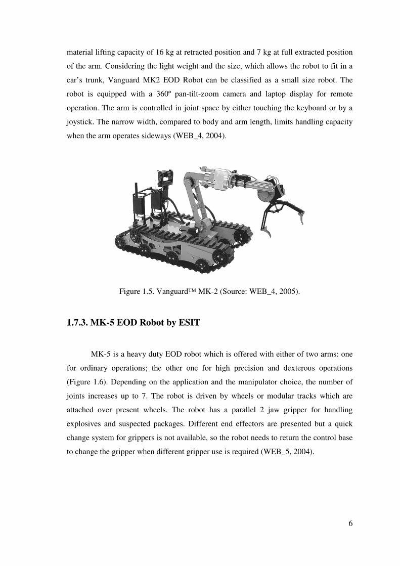
The Vanguard MK2 features an articulated arm and low profile to reach narrow
spaces such as under cars (Figure 1.5). The locomotion is provided by independently
driven tracks. The manipulator arm which has a 3 degrees of freedom excluding the 2
jaw parallel gripper having 3 degrees of freedom. The manipulator system has a
6
material lifting capacity of 16 kg at retracted position and 7 kg at full extracted position
of the arm. Considering the light weight and the size, which allows the robot to fit in a
car’s trunk, Vanguard MK2 EOD Robot can be classified as a small size robot. The
robot is equipped with a 360º pan-tilt-zoom camera and laptop display for remote
operation. The arm is controlled in joint space by either touching the keyboard or by a
joystick. The narrow width, compared to body and arm length, limits handling capacity
when the arm operates sideways (WEB_4, 2004).
Figure 1.5. Vanguard™ MK-2 (Source: WEB_4, 2005).
1.7.3. MK-5 EOD Robot by ESIT
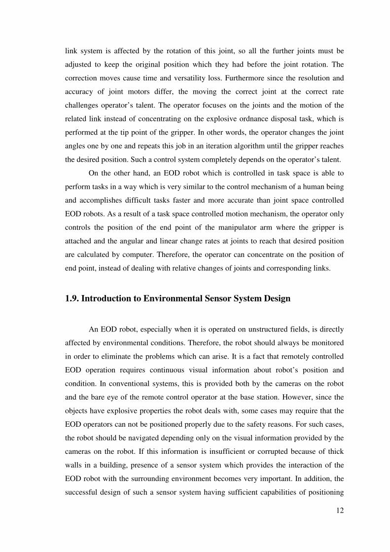
MK-5 is a heavy duty EOD robot which is offered with either of two arms: one
for ordinary operations; the other one for high precision and dexterous operations
(Figure 1.6). Depending on the application and the manipulator choice, the number of
joints increases up to 7. The robot is driven by wheels or modular tracks which are
attached over present wheels. The robot has a parallel 2 jaw gripper for handling
explosives and suspected packages. Different end effectors are presented but a quick
change system for grippers is not available, so the robot needs to return the control base
to change the gripper when different gripper use is required (WEB_5, 2004).

7
Figure 1.6. ESIT MK-5 (Source: WEB_5, 2004).
1.7.4 Wheelbarrow Super-M by Remotec Inc.
In design principle, Wheelbarrow Robot is very similar to tEODor and MK-5
robots except for its unique articulated track mechanism (Figure 1.7). This mechanism
changes the wheel positions, which provides better driving characteristics in rough
terrain. Two-way communications and vehicle/camera control can be accomplished
through wire cable, fiber optics or RF links. The Wheelbarrow Robot is equipped with
multiple television cameras for remote viewing of both the environment and the gripper
details. Depending on the end effector type, the manipulator arm has 5-7 degrees of
freedom and is actuated by both linear and rotational motors (WEB_6, 2004).

8
Figure 1.7. Wheelbarrow Super M (Source: WEB_6, 2004).
1.7.5. Robhaz-DT2 Robot
Robhaz DT2 Robot is the only non-commercial robot among the EOD Robots
stated above. It presents double tracks at each side which can rotate independent of each
other. The passive rotational joint connects the front body with the rear one, providing a
good adaptability to rough terrain conditions. In addition, the robot is equipped with a 6
degree of freedom manipulator which is controlled by a haptic joystick. The 6 degree of
freedom haptic device eases the manipulators’ control in a remarkable grade but can not
overcome joint space control problem. Since Robhaz DT2 Robot is not a commercial
project, the EOD capabilities and performance are less than the commercial robots
previously stated. However, the haptic control unit is a promising method in terms of
speed and precision compared to the traditional joint space controlled manipulator
mechanisms (Sungchul, K. and Changhyun, C., 2003).
1.7.6 BISON™ by ABP Precision (Poole) Ltd.
BISON is a four-wheel driven explosive ordnance inspection and disposal robot
(Figure 1.8). The robot is electrically driven with a DC motor powering the wheels on
each side of the vehicle. Power to the motors is provided from a pair of on-board

9
batteries. The shoulder joint is rotated by a mechanism including linear actuators so the
payload capacity is remarkably high. BISON has a relatively simple design and
construction compared to the other heavy EOD robots and this fact brings robustness
and reliability as an advantage. However, because of the simplicity of design of the
manipulator arm, BISON’s EOD capabilities in terms of handling and manipulation of
explosives are less compared to its rivals which have manipulator arms with a higher
degree of freedom. BISON’s manipulator is controlled in joint space with a remote
control handling unit including LCD display. In addition, the communication with base
and remote control is provided by cable (WEB_7, 2004).
Figure 1.8. BISON™ EOD Robot (Source: WEB_7, 2004)
1.7.7 Common Properties of Current EOD Robots
The systems are presented to the market by different arm and end effector
designs which have an average of 6-7 degrees of freedom. Considering the range of
tasks to be accomplished during operation, one type of end effector design seems
insufficient, so two or more alternative grippers are presented by the producer.
However, in order to change the end effector, the robot is returned to the base and loses
time.
Power to drive the motors and communication with base is provided usually by
cable. Some brands optionally offer RF controls and batteries to increase mobility.

10
When the working conditions are considered, the cable may get stuck or get damaged,
causing power or communication loss.
Conventional systems apply to at least two or more cameras for main and
detailed view. Commonly, one is placed at the rear part of the vehicle for a wider
looking angle and usually includes zoom, while the other placed close to the gripper
part for detailed view of the material and task. Both cameras are preferred to have a
night vision and infrared option.
However, the biggest problem about current systems is the position control
mechanism of arms and end effector. The EOD robots on the market use joint space
control in order to position the end effector which complicates the handling of the arm
and loses time and versatility. The operator controls the angle of each joint individually,
so a number of adjustments are required to reach the exact position and orientation of
the end effector. For special tasks where the precision is very important, this control
method is insufficient and too slow to accomplish the given task. Moreover, each motor
on these robots needs to be operated individually, which brings complexity compared to
autonomous mobile robots. A comparison of conventional EOD robots on market is
given in Table 1.1.

11
Table 1.1. Comparison of Conventional EOD Robots on Market.
tEODor Vanguard MK2 ESIT MK5 Wheelbarrow
Super M Robhaz
DT2 BISON
Manipulator Degree of Freedom
6 7 6 7 4 5
Control Method
Joint Space Joint Space Joint Space N/I
Joint Space (haptic device)
Joint Space
Dimensions (LxWxH)mm
1100x680x 300
920x440x 410
1170x700x 940 N/I 690x500x
910 1100x740x
1200
Weight 360 kg 55 kg 350 kg N/I 145 kg 210 kg
Manipulator's lifting capacity 20 kg 5 kg N/I N/I N/I N/I
Maximum reach of
manipulator 1750mm 1320mm N/I N/I N/I N/I
Speed 3 km/h 1-2 km/h 2-4 km/h 4 km/h 10 km/h 3,6 km/h
Autonomous N N N N N N
Quick change gripper system N N N N N N
Driving mechanism Tracks Tracks Wheels Tracks Tracks Wheels
Visual information 2 cameras 2 cameras 2 cameras 4 cameras N 3 cameras
Power supply Battery Cable (Battery opt.) Battery Battery N/I Battery
Operation distance 200 m 360 m N/I N/I N/I 1 km
Night vision Y Optional N Y N/I N
Y: Yes, N: No, N/I: No information
1.8. The Need for Task Space Controlled Operation
Although the concept of an explosive ordnance disposal robot is not an old
subject, many commercial samples have been manufactured. Although these have been
promising projects for saving human life, the operational difficulties and insufficient
motion characteristics while performing precise tasks prevent these robots from
effective application. The main reason for such operational insufficiency is the working
principle of the manipulator arm.
When the robot is operated in joint space, each of the joints is chosen
individually by the operator and actuated remotely from the base, according to the
visual information collected by the cameras. When one of the joints is rotated, all of the
12
link system is affected by the rotation of this joint, so all the further joints must be
adjusted to keep the original position which they had before the joint rotation. The
correction moves cause time and versatility loss. Furthermore since the resolution and
accuracy of joint motors differ, the moving the correct joint at the correct rate
challenges operator’s talent. The operator focuses on the joints and the motion of the
related link instead of concentrating on the explosive ordnance disposal task, which is
performed at the tip point of the gripper. In other words, the operator changes the joint
angles one by one and repeats this job in an iteration algorithm until the gripper reaches
the desired position. Such a control system completely depends on the operator’s talent.
On the other hand, an EOD robot which is controlled in task space is able to
perform tasks in a way which is very similar to the control mechanism of a human being
and accomplishes difficult tasks faster and more accurate than joint space controlled
EOD robots. As a result of a task space controlled motion mechanism, the operator only
controls the position of the end point of the manipulator arm where the gripper is
attached and the angular and linear change rates at joints to reach that desired position
are calculated by computer. Therefore, the operator can concentrate on the position of
end point, instead of dealing with relative changes of joints and corresponding links.
1.9. Introduction to Environmental Sensor System Design
An EOD robot, especially when it is operated on unstructured fields, is directly
affected by environmental conditions. Therefore, the robot should always be monitored
in order to eliminate the problems which can arise. It is a fact that remotely controlled
EOD operation requires continuous visual information about robot’s position and
condition. In conventional systems, this is provided both by the cameras on the robot
and the bare eye of the remote control operator at the base station. However, since the
objects have explosive properties the robot deals with, some cases may require that the
EOD operators can not be positioned properly due to the safety reasons. For such cases,
the robot should be navigated depending only on the visual information provided by the
cameras on the robot. If this information is insufficient or corrupted because of thick
walls in a building, presence of a sensor system which provides the interaction of the
EOD robot with the surrounding environment becomes very important. In addition, the
successful design of such a sensor system having sufficient capabilities of positioning

13
and navigating can be used for autonomous movement of mobile platform according to
the conditions of the operation area. Apart from the EOD task performed by the
manipulator which is completely under direct human interference, the motion of mobile
platform can be supported or completely accomplished by a sensor system, in order to
design an autonomous EOD robot.
1.9.1. Navigation
Navigation is the science of directing the course of a mobile robot as it traverses
the environment (land, sea, or air). Inherent in any navigation scheme is the desire to
reach a destination without getting lost or crashing into anything. Navigation involves
three tasks: mapping, planning, and driving. A higher-level process, called task
planning, specifies the destination and any constraints on the course, such as time.
Many problems have to be solved before sophisticated navigation abilities of people
will be matched by robots. Most mobile algorithms abort when they encounter
situations that make navigation difficult (McKerrow 1991).
Positioning the vehicle is one of the most important steps of navigation.
Therefore, the mobile part of the EOD robot, which carries the end effector, should be
positioned and navigated properly in order to achieve the given tasks.
The methods of positioning the robot are classified into two groups according to
which reference sources are used to receive information about the state of the vehicle.
The first one is positioning by using reference points on the field; vision based image
processing, laser, radar and sonar. The second method is positioning by absolute
coordinates; Global Positioning System (GPS).
The first technique of positioning by reference points on a plane is a vision-
based technique, in which the image of environment is captured by a video camera and
sent to a computer program where these images are evaluated. The program usually uses
colors and contrasts between textures as the reference information in order to determine
the distance and direction. Since the process depends on visual information, the
nontransparent objects between the camera and the target and dusty weather conditions
affect the success of the process (Hague et al. 2000, Jarvis 1996).
In the second technique, a laser sensor and a computer unit are installed on top
of the vehicle (or on the end-effector) and a number of passive reflectors are placed at
14
the corners and along the sides of the field. The sensor head transmits a beam of pulsed
laser light in different directions as it rotates around an approximately vertical axis, and
the beam of laser light spreads out in a vertical direction. Some of the transmitted laser
light is reflected by the successively traversed reflectors of which the x, y and z
coordinates should be known in a local earth- 3D coordinate system (Sogaard 1999).
The other technique, based on the same principle, uses a radar signal that is
reflected from natural forms or artificial reflectors to evaluate and construct a digital
map of the field. Therefore, besides positioning the robot, obstacle detection is also
provided. The image of the field obtained by radar signals is approximately similar to
those obtained from nautical applications. Although the accuracy is not high, the
usability of radar over long distances is an advantage of this technique.
Ultrasonic systems use ultrasonic waves for positioning and object detection. In
most applications, the sound waves are sent by a rotating emitter, placed on top of the
vehicle. The computer measures the distance between the vehicle and an object or a
landmark by computing the time of flight of the sound wave. It is also reported that
sending a burst of ultrasound instead of a continuous emission and then computing the
environment by changes in the frequency and amplitude is also possible. Since the
computer uses a frequency spectrum for evaluation, the type of the object can also be
recognized up to a level (Harper 2001).
The unique technique of positioning a mobile robot by using absolute or earth-
fixed coordinates is called as Global Positioning System (GPS). This device is locked to
at least three different satellites for planar positioning and four satellites for the
calculation of elevation, and uses triangulation to identify any position on earth.
However, the use of GPS in outdoor applications has not shown to be sufficiently
accurate for guiding a vehicle over rough terrain until recently, because of the time
delay caused by the signal’s travel to the satellite and back. Moreover, positioning
systems using GPS need assisting devices (gyro, compass or accelerometer) in order to
decrease the error (Thuilot et al. 2001). The fact that any of these sensor techniques has
advantages and disadvantages in comparison to each other, means that positioning a
land vehicle by combining more than one technique will aide in eliminating the
disadvantages of each technique. This will provide more accurate sensor systems for all-
terrain mobile robots.

15
1.10. Current Conventional Sensor Systems
1.10.1. Vision System
The vision system consists of a video camera and a computer unit to process the
captured images. While this system is locating the position of the robot, it can also
measure the position of the objects in the image frame. Therefore, when comparing the
image to a pre-defined pattern, the system can recognize the scene or the object itself.
Moreover, vision is the only system which can recognize the color of the object.
On the other hand, extracting useful information from images is a difficult task
considering that the system has to deal with natural objects under natural lighting
conditions. Moreover, high-power computers are required for complicated images. The
success of measuring the depth of objects from one frame of image is not sufficient for
precise positioning, especially when the blurring due to vibration is considered. Since
processing images mainly depends on color and contrast difference in the image frame,
the accuracy of vision systems is mixed and usually depends on the application.
1.10.2. Laser System
The laser system depends on the evaluation of reflected laser beams, which are
emitted by a unit mounted on the mobile platform. One of the biggest advantages is its
simplicity in terms of the principle and the application. In addition, conventional laser
systems are very common as measurement devices in industry so this availability means
that various types are accessible at a comparatively low cost. Furthermore, the main
advantage of this sensor system is that it is not affected by lighting conditions.
Nevertheless, laser systems which rely on a vehicle mounted laser have a significant
drawback when used on rough terrain. The tilt of the mobile platform of robot may
cause the laser beam to miss the targets, unless the beam is diverged vertically. This
divergence seriously reduces the practical operating range since the output power is
limited by the need for the system to be eye-safe (Hague et al. 2000). Also, a high
amount of dust or fog can interfere with the system.
16
1.10.3. Radar System
Radar is used for measuring the distance of a vehicle to natural and artificial
landmarks or objects in an outdoor field. The working principle in robotic applications
is very similar to those used in naval applications; radar signals are emitted, and then
reflected from the objects. Common radar applications apply some artificial reference
landmarks, which are set on fields and define the position of vehicle by triangulation of
their distances to the EOD robot (Hague et al. 2000).
One of the most important advantages is that a range of a few hundred meters
can be achieved, despite the fact that the beam is being diverged vertically to
accommodate a small degree of vehicle tilt. Also, radar systems are less susceptible to
climatic disruption than optical sensory systems.
1.10.4. Sonar System
Sonar sensors emit sound waves and measure the time of flight between the
sensor and the object. By computing this flight time, the distance can be found easily
because of the fact that sound waves move with a constant speed in the air. In most
applications sound waves are emitted frequently and the calculations focus on the time
it takes the sonic waves to reach a reflective surface and come back to the receiver part
of the sensor.
Depending on the type of pulse emission, different types of objects can be
recognized by evaluating the frequency spectrum of waves reflected from the object (an
experimental system can recognize four different types of trees). As another advantage,
common ultrasonic sensors are inexpensive and widely used in industrial applications.
However, these sensors are sensitive to air movement and ambient ultrasonic
noise, a great deal of which may be generated by the robotic vehicle itself. Also, data
refreshing time is low for high distances because of the pause for time of flight
calculations.
17
1.10.5. Global Positioning System (GPS)
GPS measures distance using the travel time of radio signals from the satellites
in the earth’s orbit to the GPS device on earth and the position is calculated by a
triangulation method. In order to measure accurate travel time and position, the GPS
device should be locked to at least four satellites.
Moreover, in order to achieve higher accuracy than that obtained by a regular
GPS device advanced systems called Differential GPS (D-GPS) and Real-time
Kinematic GPS (RTK-GPS) can be used. These systems use a beacon station on the
earth’s surface to compare the information received from satellites so that the errors
caused by environmental effects can be reduced (Romans et al. 2000). The accuracy
increases as the distance between the vehicle and the beacon station decreases.
The need for a number of beacons, which are required for laser and radar
systems and the difficulty of positioning them in a precise geometry, is eliminated and
centimeter level accuracy is provided with D-GPS or RTK-GPS. These systems are not
affected by vibration, sound and vehicle orientation. Also, for advanced devices, it may
be assumed that weather conditions will not impair their efficiency.
Since GPS technology requires no reference information from the ground, the
problems related to wheel slippage will be overcome easily.
However, time delay caused by signal processing to determine the location and
orientation challenges the control system at high field speeds (Wilson 2000). In
addition, the system is affected by the presence of buildings, trees or steeply rolling
terrain, and interruption in satellite or differential correction signals. Also, since it uses
absolute coordinates instead of environmental information, assisting devices are
required for accurate measurement in vertical coordinates, which means some extra cost
and processing time.

18
Table 1.2. Comparison of sensor systems capability.
Vision Laser Radar Sonar GPS Pit, cavity, negative height recognition
Y Y N Y N
Positive height obstacle recognition
Y Y Y Y N
Affected by rain, fog, dust Y Y N N N Affected by tilting N Y N N N Affected by vibration Y N N N N Affected by sound (noise) N N N Y N Object identification Y N N Y N Precise sensor geometry requirement
N Y Y Y N
Beacon requirement N Y Y N N Availability on market Y Y N Y Y Distance measurement N Y Y Y N
Y: Yes, N: No
Table 1.3. Comparison of sensor systems qualifications.
VISION LASER RADAR SONAR GPS
Data refreshing time 1 2 2 2 3
Processing time 1 2 1 2 1
Cost 1 1 2 1 3
Accuracy 2 1 1 2 2
Range 2 3 2 3 1
1: lowest cost, fastest time, high accuracy, highest range;
3: highest cost, slower time, low accuracy, lowest range
1.11. Environmental Sensor System Related Problems
Natural conditions are obviously the most challenging problems encountered in
all-terrain mobile robot applications. Because weather conditions can rapidly change
and dramatically vary even between two sections of a field, most of the robotic
experiments and applications focus on the solution of a limited number of outdoor

19
problems and others assume ideal conditions. The main problems encountered by an all-
terrain mobile robot can be summarized as follows.
1.11.1. Paddles
Natural pits filled with water because of weather conditions can create obstacles
when they are not previously detected. When using conventional type sensors, the water
surface is recognized as a flat plane containing no obstructions and in this situation, the
vehicle advances and falls into the pit. The problem occurs when the depth of the water
may exceed the allowable value for the vehicle to operate (Figure 1.9.)
Figure 1.9. Natural pit filled by water on the way of the vehicle.
1.11.2. Shading
Many outdoor tasks including searching, finding and recognizing the target
occurs in a complex medium. Some features of the object itself may shade the target, or
it may not have a distinct shape and color.
1.11.3. Sensor Tilt
Outdoor fields are unstructured so they have rough surfaces, which cause sudden
changes in orientation and altitude. When the sensor is mounted on the vehicle with a
specific geometry and direction, change in the vehicle orientation causes change in the

20
geometry of sensors with respect to the ground, which will result in the sensors missing
the target which can be either a beacon or an obstacle (Figure 1.10.).
Figure 1.10. Signal is interrupted because of sensor tilting in rough surfaces.
1.11.4. Lighting
The outdoor areas are usually under the effect of natural lighting conditions
defined by the position of the sun. However, natural conditions may rapidly change and
cause unpredictable situations. For example, a cloud passing over the vehicle on a sunny
day affects the vision sensor whose settings are done for daylight conditions.
1.11.5. Weather Conditions
Heavy rain, a thick layer of fog and excessive dust which often behave like a
curtain between the sensor and the target, prevent the laser or radar signals from
passing. In addition, the systems using visual information are also affected by heavy
weather conditions.

21
1.11.6. Slippery Terrain
The surface of the terrain may be loose or slippery, which causes the odometric
sensors to read faulty measurements when the measurement is done by tracking the
wheels of the vehicle or a separate sensor wheel.
1.11.7. Vibration
Since the outdoor fields are unstructured and naturally formed, the irregularities
in the surface of the field causes vibration which affects the systems using visual
information and the result is blurring on the captured image.
Figure 1.11. Height difference in topography hinders signals to/from the beacon.
1.11.8. Beacons
In some fields, because of the large number of trees or rapid changes in altitude,
the communication with the reference points, which defines the position of vehicle with
respect to the field, may be interrupted or lost. This is the dilemma created when using
sensor systems requiring beacons. For many systems, the maximum height difference of
the field should not exceed 2 meters to operate properly (Figure 1.11).

22
CHAPTER 2
SYSTEM ELEMENTS
The robot is comprised of three main sections which are a mobile platform, a
manipulator arm and a gripper (Figure 2.1). The reason for such a classification is that
each of these sections is controlled independently during an EOD operation.
Figure 2.1. The EOD Robot.
2.1. Mobile Platform
This section is the main body of the robot, which is moved on rubber tracks
driven by electric powered motors. Since tracks have high traction characteristics on
rough terrain compared to wheels, the robot is designed to have tracks. Moreover, the
vehicle has high maneuvering ability due to the motion principle of tracks. The 150mm
wide rubber tracks are the same as the ones used by conventional light-duty loader
vehicles so they can be easily supplied from the market.

23
The tracks are wound around two 200 mm wheels and one 160mm sprocket
wheel which is placed at the front. Three additional wheels including suspensions
provide permanent contact with ground and increase traction on rough and slippery
terrain (Figure 2.2).
Figure 2.2. Suspension mechanism of assistant wheels.
The sprocket of each track is powered by an independently driven electrical
motor providing high maneuvering characteristic at limited volumes (Figure 2.3). Each
of the motors has an output torque of 15 Nm which is transmitted to the sprocket wheel
by a heavy duty gear box having 1:15 reduction ratio. Being powered by this motor and
gearbox configuration, the robot is capable of climbing inclined surfaces of more than
45° and reaching up to a speed of 3 km per hour. Since higher velocity is not necessarily
required for EOD tasks, high reduction rate gear boxes are used to provide high output
torques from moderate motor powers.

24
Figure 2.3. Tracks and driving motors.
Obstacles measuring up to 0.28 m in height can be passed without any difficulty.
It is also possible to drive up or down stairs and slopes with inclines of up to 40°, as
long as the traction between the stairs and the tracks is sufficient. Since the vehicle has a
compact size and can climb stairs, the vehicle can pass through doors and operate in
buildings and other confined areas.
Most of the body mass of the mobile platform is placed between the tracks
keeping the center of gravity as low as possible. As a result of this design, the front and
rear downhill gredability is up to 45°; cross-hill gradability is 42° having if the
manipulator arm folded (Figure 2.4). The position of batteries on the robot also
increases stability when the manipulator arm is fully extracted forward. When the arm is
fully extracted forward gripping a load of 10 kg, front downhill greadability is 32º. On
the other hand, during an operation with the manipulator fully extracted to sideways, the
robot keeps its lateral stability up to the inclination of 33º.

25
Figure 2.4. Stability of the EOD robot on inclined surfaces.
Besides the drive units and transmission, the main body of the mobile platform
contains electronic circuits, laptop, batteries, a tele-operation unit and a vision system.
The power needed for electric motors on the robot is supplied by two tractional type
conventional gel batteries, which are commonly used for electrical loaders. Batteries
can be slid out from the back part of vehicle without removing the body panels avoiding
the necessity of moving the arm to a suitable position and lifting the batteries each of
which weighs approximately 36 kg (Figure 2.5).
The weather-proof body of the EOD Robot is the result of 2mm-thick sheet
metal panels which can be removed easily for quick intervention to internal sections.
26
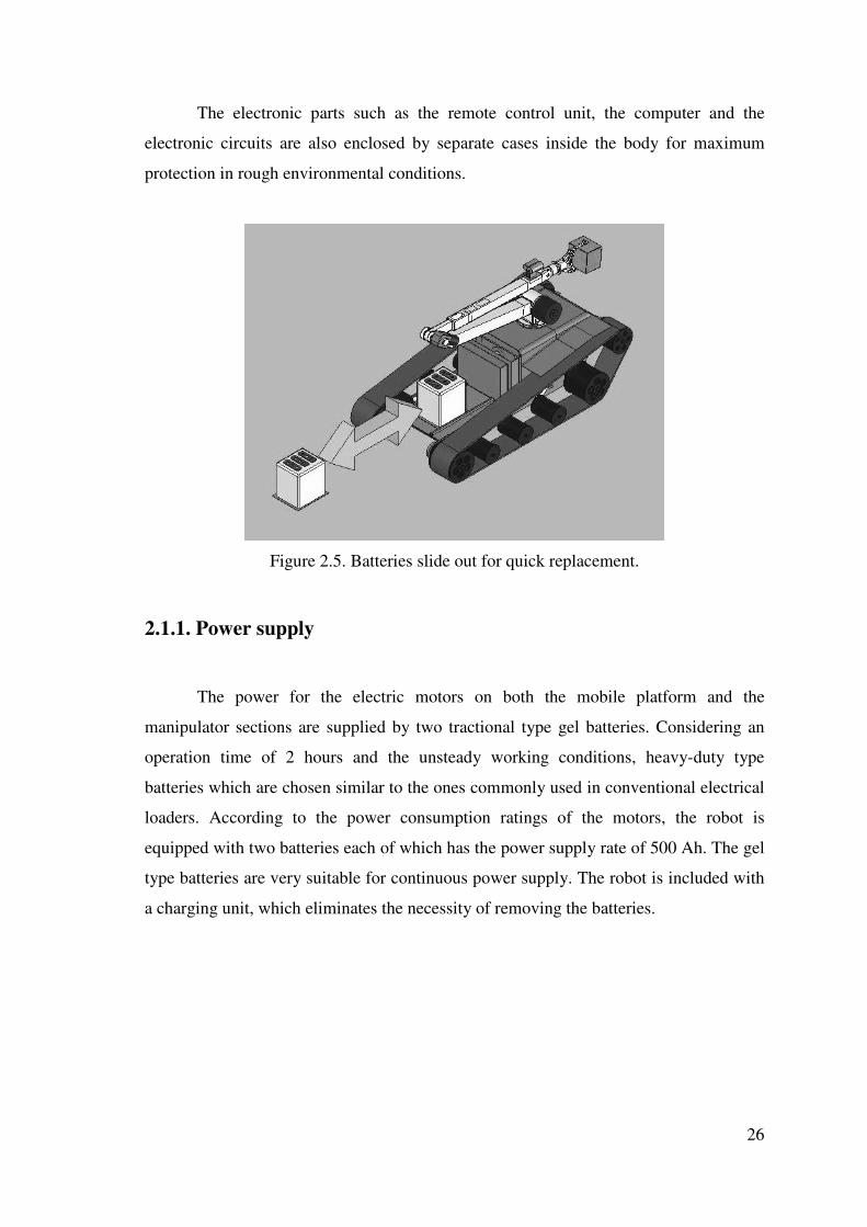
The electronic parts such as the remote control unit, the computer and the
electronic circuits are also enclosed by separate cases inside the body for maximum
protection in rough environmental conditions.
Figure 2.5. Batteries slide out for quick replacement.
2.1.1. Power supply
The power for the electric motors on both the mobile platform and the
manipulator sections are supplied by two tractional type gel batteries. Considering an
operation time of 2 hours and the unsteady working conditions, heavy-duty type
batteries which are chosen similar to the ones commonly used in conventional electrical
loaders. According to the power consumption ratings of the motors, the robot is
equipped with two batteries each of which has the power supply rate of 500 Ah. The gel
type batteries are very suitable for continuous power supply. The robot is included with
a charging unit, which eliminates the necessity of removing the batteries.

27
2.1.2. Cameras
The robot includes two high resolution color cameras; a wide-angle zoom
camera mounted on the rear side of the chassis, and a smaller detail camera mounted
close to the end effector for a detailed view of the task. The scene of the task space,
received from both cameras, is displayed on a laptop monitor at the control base and the
images can be switched depending on the requirements of the operation.
Figure 2.6. Main view camera.
The main camera is mounted on a telescopic turret on the back-side of the
chassis for viewing both the mobile platform and manipulator arm (Figure 2.6). The
turret has a vertical telescopic stroke of 400 mm and the camera is designed to rotate on
a horizontal and vertical plane. This 3 degree of freedom motion characteristic of the
main camera provides remarkable versatility during operation. Since the camera is
controlled independently from the motion of mobile platform and manipulator, the
operator can move the camera to change the looking angle of the target when the visual
information is interrupted by an obstacle, which may be even the moving manipulator
itself. The main camera is equipped with a night vision system to operate in darkness
where the circumstances prohibit the usage of lights. The camera control will also be

28
equipped with a “follow” function so that when the manipulator arm is moved, the
camera will follow the gripper.
Details of the EOD process are monitored according to the visual information
collected by the detail camera attached to the front section of the manipulator arm
(Figure 2.8). The detail camera has a fixed position at the end of the manipulator arm
and the viewing angle is directed to the effective task space of the gripper.
Figure 2.8. Detail camera
2.2. Manipulator Arm
2.2.1 Operation Principle
The manipulator mechanism of the robot can be classified in two sections
according to the control mechanism; the arm and the gripper. The manipulator arm is
the task space controlled part of the EOD system. The motion of the arm is provided by
four electric motors and the angular rotation or linear extension is controlled by optical
encoders. Being controlled in task space, the end point of the manipulator arm follows a
smooth trajectory. Once the end point of the arm which is also the connection point with
the gripper joint is moved to the desired position, the operator actuates the motors on
the gripper to accomplish the EOD task. Each motor on the gripper is controlled
independently from the other motors on the gripper and also those on the arm.

29
According to the task space controlled operation principle, the operator just
defines the desired position of the end point of the arm by looking at the cameras and
then the motion of manipulator arm is controlled by the laptop on board. After the
coordinates of the target position are located, the rotation angles of joint motors on the
manipulator arm are calculated by the computer and the arm is moved to position the
gripper. The motion of the links and joint rotations are controlled by sensors at each
joint and errors are compensated by the adaptive control algorithm of the computer
program. Moreover, the control system can simply evaluate the priority of joint motions
in terms of precision, speed and power consumption in order to work more efficiently.
The reason for limiting the task space controlled operation only to the arm
instead of the whole manipulator system is due to the difficulty of controlling a
manipulator having a redundant number of joints and also readjustment of control
parameters for different gripper types.
2.2.2. Mechanical Properties of Manipulator Arm
The manipulator arm is responsible for precisely locating the end effector to the
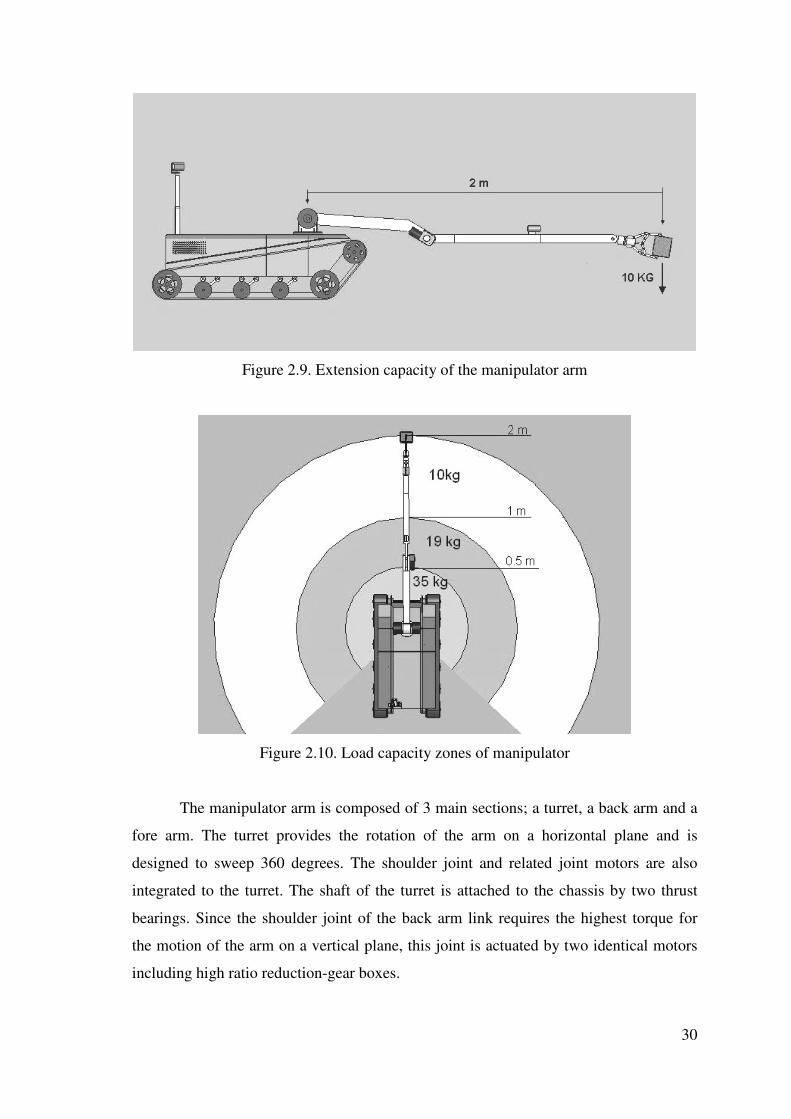
desired position. The arm has a capacity of handling materials up to 10 kg and a
maximum reach of 2 meters at the full extended position (Figure 2.9). This property
provides an advantage to the robot in special situations where the mobile platform
cannot move further because of its size. For the cases that the explosive material’s
weight or size is beyond the arm’s handling capacity, the robot can pull the material to a
safer area. However, in the case that the operation condition allows the robot to
manipulate the object from a distance closer than 2 meters, the robot’s lifting capacity
increases favorably. An illustration for the lifting capacity of the robot according to the
object distance is shown in Figure 2.10.
30
Figure 2.9. Extension capacity of the manipulator arm
Figure 2.10. Load capacity zones of manipulator
The manipulator arm is composed of 3 main sections; a turret, a back arm and a
fore arm. The turret provides the rotation of the arm on a horizontal plane and is
designed to sweep 360 degrees. The shoulder joint and related joint motors are also
integrated to the turret. The shaft of the turret is attached to the chassis by two thrust
bearings. Since the shoulder joint of the back arm link requires the highest torque for
the motion of the arm on a vertical plane, this joint is actuated by two identical motors
including high ratio reduction-gear boxes.
31
The extensible telescopic fore arm link is composed of two sections, one of
which slides inside the other through a linear joint extending 400 mm. The main
purpose of designing a linear joint is to increase the manipulator’s versatility in such
cases that the EOD operation takes place in a narrow place where there is no sufficient
space for the rotational motion of links. This feature provides the user with numerous
additional advantages when manipulating objects, such as; the insertion of keys into
keyholes, the direct usage of tools during operation (e.g. an electric drill), and an
especially long reach in hard-to-access areas (i.e., under a vehicle).
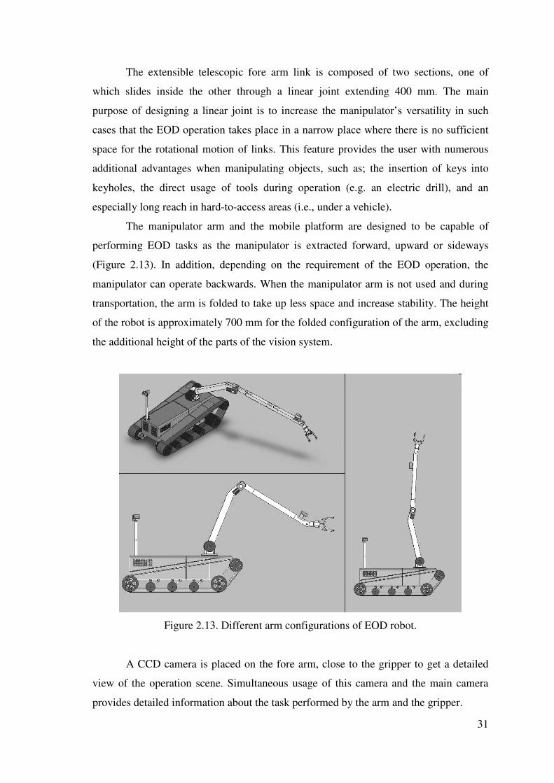
The manipulator arm and the mobile platform are designed to be capable of
performing EOD tasks as the manipulator is extracted forward, upward or sideways
(Figure 2.13). In addition, depending on the requirement of the EOD operation, the
manipulator can operate backwards. When the manipulator arm is not used and during
transportation, the arm is folded to take up less space and increase stability. The height
of the robot is approximately 700 mm for the folded configuration of the arm, excluding
the additional height of the parts of the vision system.
Figure 2.13. Different arm configurations of EOD robot.
A CCD camera is placed on the fore arm, close to the gripper to get a detailed
view of the operation scene. Simultaneous usage of this camera and the main camera
provides detailed information about the task performed by the arm and the gripper.

32
2.3 Gripper (End Effector)
The gripper parts are the end effector of the whole system which is designed to
accomplish the special EOD tasks. There are 4 types of grippers for different purposes
which are attached to the manipulator arm with a multi-purpose changeable joint. The
gripper is controlled independently from the manipulator arm, so that the operator does
not struggle with the less sensitive, higher powered joint motors of a manipulator arm.
The gripper control is activated after the manipulator reaches the desired position.
2.3.1. General Purpose Gripper with 2 Jaws
The robot has a general purpose 2 jaw gripper for basic material handling tasks
(Figure 2.14). The gripper is designed to hold 15 cm wide materials with a maximum
weight of 10 kg. The gripping force which is supplied by a linear actuator, is transferred
and increased by a simple four bar link mechanism, rubber coverings are used in order
to increase friction at the touching surface of the tips of the gripper. The gripper has
three degrees of freedom and is controlled independently from the control of the arm.
Figure 2.14. General Purpose gripper with 2 jaws.

33
2.3.2. Cylindrical Object Gripper with 3 Jaws
This type of gripper is designed to handle cylindrical objects (Figure 2.15), since
many explosive materials have cylindrical shapes, such as bombs, landmines, and
triggering mechanisms of some unexploded ordnances. The 3 jaw gripper can support a
cylindrical object from every direction and provide higher friction. The gripper is able
to rotate 360 degrees about its own axis which enables unscrewing cylindrical parts
such as disintegrating an unexploded bomb’s triggering mechanism (Figure 2.16).
Figure 2.15. Gripper with 3 jaws.
Figure 2.16. Removing the triggering mechanism of an unexploded bomb.

34
2.3.3. Screwing Apparatus
Most of the explosive mechanisms are placed in a shell in order to minimize the
possibility of external intervention as well as the environmental effects. In many cases,
bomb technicians use a common screw apparatus to remove the shell which involves
taking great risks. In order to eliminate the risk of screw or bolt handling on explosive
mechanisms, the EOD robot is equipped with a special end effector which includes
different screwdriver heads, so that the screws on the explosive ordnance can be
tightened or loosened. The gripper head includes phillips and slotted screwdriver tips
and an adjustable wrench for bolts (Figure 2.17).
Figure 2.17. Screwing apparatus.
2.3.4. Cutting Apparatus
Depending on the position of the target object, manipulation of the objects can
be obstructed by a material such as a wooden box or metal shell. Also, some cases may
require that obstructing materials should be removed away in order to clear the
operation area. In such cases, the end effector, equipped with a cutting blade which is
similar to conventional types, cuts out the obstructing material which is preventing the
manipulator from reaching the explosive ordnance (Figure 2.18). The linear motion
provided by the telescopic joint on the manipulator arm, is very advantageous when
performing the cutting task.

35
Figure 2.18. Cutting apparatus with a circular blade.

36
CHAPTER 3
KINEMATIC ANALYSIS OF THE MANIPULATOR ARM
The work space of the arm and calculation of joint parameters for positioning
the end effector are provided by kinematic analysis. At this point, there appear to be two
types of kinematic analysis; direct kinematics and inverse kinematics. Direct kinematics
is simply the method of calculating equations of the end effector position for the given
joint parameters. On contrast, by inverse kinematic analysis, the equations of joint
parameters are found according to the end effector position (Crane III., 1998).
3.1. Direct Kinematic Analysis of the Manipulator Arm
Although the EOD robot is designed to be controlled in task space, the forward
kinematic analysis should be calculated in order to define the link and joint positions
and motions which are needed to calculate dynamic analysis of the manipulator arm.
Moreover, direct kinematic analysis is applied for obtaining the error between the real
position and desired position of the gripper as feedback (Sciavicco, 2003).
For the purpose of calculating the direct kinematic analysis, the robot is thought
of as a set of rigid links connected together at various points and the Denavit-
Hartenberg Method is used. The Denavit-Hartenberg Method provides a representation
of positions of link frames relative to each other by two rotations and two transition
matrix transformations. According to this method first, link parameters are defined and
the transformation matrices are formed according to these parameters (Table 3.1). The
values of position and orientation of the end effector relative to the base frame are
calculated by the multiplication of these matrices (McKerrow, 1991).

37
Table 3.1 Denavit-Hartenberg parameters of the manipulator arm.
�i �i ai di
Link 1 �1 90 0 0Link 2 �2 0 l2 0Link 3 �3 90 0 l3Link 4 0 0 0 l4
According to the parameters listed in Table3.1., the D-H transformation matrices are
found as follows;
����
�
�
����
�
�
−=
100000100000
11
11
1
θθθθ
CosSin
SinCos
AR (3.1)
����
�
�
����
�
� −
=
10000100
00
2222
2222
21 θθθ
θθθSinlCosSin
CoslSinCos
A (3.2)
����
�
�
����
�
�
−=
10000010
00
3333
3333
32 θθθ
θθθSinlCosSin
CoslSinCos
A (3.3)
��������
�
�
��������
�
�
−=
1000
)2
(010
0000
0000
4
43
lhA (3.4)

38
where 1A , 2A , 3A and 4A are the transformation matrices of frames attached to joints 1,
2, 3 and 4 respectively. The parameters l2, l3, refer to lengths of link 2 and link 3, while
l4 and h refer to the extension length and the total length of link 4respectively. The
position and orientation of the end frame according to the reference frame, which is the
center of rotation at the shoulder joint for the EOD robot's manipulator arm can be
found by multiplication of these matrices as;
������������
�
�
������������
�
�
���
�
�
�
−++
+++−+
���
�
�
�
−+−
+++−−
���
�
�
�
−+−
+++−
=
1000
))2)((21
)()(0
))2)((
)(22(21
)(
))2)((
)(22(21
)(
432
33222
323223
432
332221321132323
432
332221321132321
4
lhC
lSlSCSCSC
lhS
lClCSSSCSSCCS
lhS
lClCCSCSSSCC
TR
θθ
θθθθθθθθθ
θθ
θθθθθθθθθθθθθ
ϑϑ
θθθθθθθθθθθθθ
(3.5)
The representations iCθ and iSθ refer to iCosϑ and iSinθ respectively. The
3x3 part of the transformation matrix formed by the elements included in the first 3
rows of the first 3 columns defines the orientation of the end frame while the 3x1 matrix
formed by the first three rows of the 4th column defines the position.
3.2. Inverse Kinematic Analysis of Manipulator Arm
Since the EOD robot is controlled in task space, correct evaluation of inverse
kinematic analysis has a vital importance in order to compute the correct joint
parameters. However; this task becomes complicated as the number of links and joints
increase.
The arm consists of three revolute joints and one prismatic joint each having one
degree of freedom. The total degrees of freedom of the manipulator arm is 4 for the
manipulator arm, excluding the end effector and mobile platform. Considering the
platform of the robot stands on a flat horizontal surface, one of the revolute joints
moves on a horizontal plane and two of them on a vertical plane.

39
For the task of positioning an object, a Cartesian coordinate frame is considered,
a manipulator with 4 degrees of freedom brings a redundancy problem during the
positioning of the end effector. However, considering the versatility provided by this
additional linear joint, the control problem caused by this redundancy is justified.
The task space control requires the joint rotation angles according to a desired
end effector position. Therefore, an inverse kinematic analysis should be applied. The
inverse kinematic analysis task can be defined briefly as obtaining the joint angles for a
given position of the end point. During the operation of the robot, the inverse kinematic
calculations are performed by the computer on-board.
Since the manipulator arm is composed of 4 serial links and the configuration is
relatively simple, a trigonometric approach is applied to complete the inverse kinematic
analysis of the manipulator arm (Sponge and Vidyasagar, 1989).
Figure 3.1. The motions of manipulator arm joints.
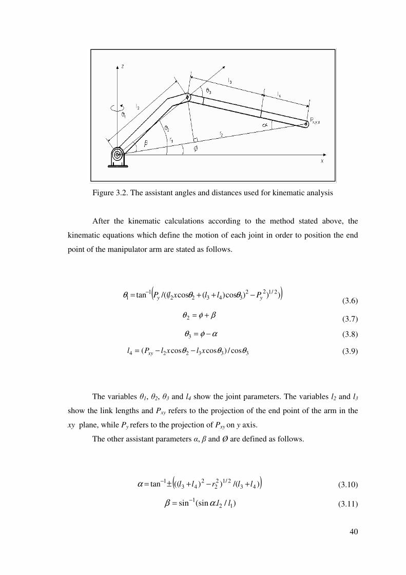
In order to ease the calculation of �1, �2 and �3 angles and l4 distance which
bring the end point of the arm to the desired position, the angles �, � and Ø and
distances r1 and r2 are introduced (Figure 3.2.).
40
Figure 3.2. The assistant angles and distances used for kinematic analysis
After the kinematic calculations according to the method stated above, the
kinematic equations which define the motion of each joint in order to position the end
point of the manipulator arm are stated as follows.
( ))))cos)(cos/((tan 2/12234322
11 yy PllxlP −++= − θθθ
(3.6)
βφθ +=2 (3.7)
αφθ −=3 (3.8)
333224 cos/)coscos( θθθ xlxlPl xy −−= (3.9)
The variables �1, �2, �3 and l4 show the joint parameters. The variables l2 and l3
show the link lengths and Pxy refers to the projection of the end point of the arm in the
xy plane, while Py refers to the projection of Pxy on y axis.
The other assistant parameters �, � and Ø are defined as follows.
( ))/())((tan 432/12
22
431 llrll +−+±= −α (3.10)
)/.(sinsin 121 llαβ −= (3.11)

41
)/(tan ,1
zyx PP−=φ (3.12)
where Pz defines the projection of end point of manipulator arm on the z axis.
The “±” symbol which belongs to � angle shown above in the assisting angle
equation states that for any position of the end point of the manipulator arm apart from
singularity points, there appear to be 2 different solutions as the length l4 is maintained.
The assistant parameters r1, r2 which are used to calculate the assisting angles, are
formulated as follows.
2/1243
222
2243
22
2
2 ))(()(2
))((lll
PP
lllPPr
zxy
zxy +−−+
+−++=
(3.13)
2/1222/1243
222
2243
22
2
1 )())(()(2
))((zxy
zxy
zxy PPlllPP
lllPPr +−
��
�
�
�+−−
+
+−++=
(3.14)

42
CHAPTER 4
DYNAMIC ANALYSIS OF THE MANIPULATOR ARM
In order to control the manipulator arm of the EOD robot in task space, the
dynamic analysis of the arm should be calculated and the generalized force equations
should be obtained according to the robot configuration. The dynamic analysis in this
study is accomplished by Lagrange formulation method.
The Lagrangian formulation describes the dynamic behavior of a robot in terms
of the work done by, and energy stored in the system. The arm is treated as a black box
that has an energy balance. The constraint forces are eliminated during the formulation
of the equations. As with Lagrangian dynamics, the closed-form equations can be
derived in any coordinate system.
According to Lagrange method, kinetic energies of all the links of the
manipulator arm are summed and the difference between the potential energies is
calculated.
In this method, first the kinetic energy of each link is calculated depending on
the center of gravity of the link, and later the difference between the sum of the kinetic
energy and the sum of the potantial energy of the links are calculated. This difference
discribes the Lagrangian of the system. By taking the derivative of the Lagrangian
depending on the time change of the joint velocities and joint position and calculating
the difference yields the generalized force needs to be applied to each joint.
��
�
�
�
∂
∂−
��
�
�
�
∂
∂=
nnn
q
L
q
L
dt
dF
� (4.1)
In equation (4.1), Fn refers to the generalized force while n and L refer to joint
number and Lagrangian value, respectively (Sponge, 1989; McKerrow, 1991).
( ) UKqqL nn −=�, (4.2)

43
In order to compute the kinetic energies, the linear and angular velocities of
links of the manipulator arm should be calculated. Angular velocities can be defined as
the rate of change of the angle of joints in time. In other words, the angular velocity is
the rotation of output shaft of the related joint motor. The angular velocities of revolute
joints are stated below;
���
�
�
���
�
�
=0
0
101 θ�w = 1θ� (4.3)
���
�
�
���
�
�
=+=
2
12
12
01
12
02
02
θθθθθ
�
�
�
Cos
Sin
wRww (4.4)
���
�
�
���
�
�
+=+=
32
12
12
02
12
23
03
θθθθθθ
��
�
�
Cos
Sin
wRww (4.5)
Since, the 4th joint is linear, angular velocity of link 4 is same as the link 3;
���
�
�
���
�
�
+=
32
12
12
04
θθθθθθ
��
�
�
Cos
Sin
w (4.6)
Linear velocities of the links are found by calculating the positions of the link
frames according to the reference frame which is calculated by Denavit-Hartenberg
transformation matrices, and then the derivative of the resulting matrix is computed
according to the joint angle parameters. Eventually, the linear velocities are calculated
as follows;
010 =V (4.7)

44
���
�
�
���
�
�
−−−
=
221
22211212
22211212
20
θθθθθθθθθθθθθθ
�
��
��
lCoslSinSinlCosCos
lSinCoslSinCos
V (4.8)
=30V
���
�
�
���
�
�
++++++−++−+−++−++−+−
3322223323
3322221332221133231
3322221332221133231
)()()())()()())()(
lClClC
lSlSSlClCClSS
lSlSClClCSlSC
θθθθθθθθθθθθθθθθθθθθθθθθθθθθθθθθθθθ
��
���
���
(4.9)
�����������������
�
�
�����������������
�
�
−−++−−+−
−−++−+
+−−+−
−+−−+−+
+−−+−
=
))2(21
())2(21
(
)))2(22())2(
22())2(2((21
)))2(22())2(
22())2(2((21
4233232224233233423
4233232211423
32322214233233132341
4233232211423
32322214233233132341
40
lhSlClClhSlClC
lhSlClCClhC
lSlSSlhClSSlSlS
lhSlClCSlhC
lSlSClhClSClSlC
V
θθθθθθθθ
θθθθθθ
θθθθθθθθθ
θθθθθθ
θθθθθθθθθ
���
�
���
�
���
(4.10)
When the calculated velocities are applied to the kinetic energy formula;
22
21
21
nnnnn wIVmK += (4.11)
kinetic energies of links are calculated as follows;
211 2
1 θ�IK = (4.12)
)(21
)))((((21 2
22
1222
22
212
222 θθθθθ ���� +++= IlCosmK (4.13)

45
))(((21
))))2(
)((((21
232
213
23323
22
22
232322
21
23
2333
θθθθθ
θθθθ
����
��
++++++
++=
IlllCosl
lCoslCoslmK (4.14)
)))))}2)2((2(8
))2(2(28(
)))2())2(48(
)44())2(4((28(81
{(21
412332322
24323323
22
22
21
2443332
23
22
22
24
23
23
2444
lhCosSinlCoslCos
lhlSinlCoslCos
lhlhSinlCosl
lllhllmK
+++−+−++
−+−−+
++−++=
θθθθθθθθ
θθ
θθ
�
���
(4.15)
and the potential energies of linkages are calculated as follows;
01 =U (4.16)
gmSinlU 2222 θ= (4.17)
gmSinlSinlU 333223 )( θθ += (4.18)
gmSinh
llSinlU 4343224 )))2
((( θθ −++= (4.19)

46
Then, the Lagrange equation is formed according to the kinetic and potential energy
equations;
gmSinh
llSinlgmSinlSinl
gmSinlIlhCosSin
lCoslCoslhSinlCos
lCoslhlhSinlCoslll
lhllmI
lllCosllCoslCoslm
IlCosmIL
43432233322
2222
322
144123
323222
423323
222
221
2443332
23
22
22
24
23
23
244
232
213
23323
22
22
232322
21
23
233
22
212
22
22
212
22
21
)))2
((()(
)(((21
))))))22(
2(8))2(2(2
8()))2())2(48(44(
))2(4((28(81
((21
))(((21
))))2())((((21
)((21
)))(((21
21
θθθθ
θθθθθθ
θθθθθθθθθ
θθθθ
θθθθθθ
θθθθθθ
−++−+−
−++++
+−+−+
+−+−−+++
−++++++
++++++
++++=
���
��
�����
���
�����
(4.20)
By using the Lagrangian calculated in equation (4.20), the generalized forces for each
joint are found as;
42232
121112221
22
21323123
213223231232
23223232233232212
2122
22144232
12
43223231232
14
12323443223423231132
234323214414132232
2322421322323121
231221211424232
1432
23231232
14232
11322323423
12321322322322432
321232
232311322343122
122242232232312314411
)2(
))(2()
))(((2)
2()2)))(2(((
))))((()))(
(((2)))(()))(
(((2))))(()2(
)))2()2(2((()())(
2(())(2(
))(((2
))()))((()
2())(2(41
mlSinCoshSinIml
CosImlCosSinCosCosCos
CosSinCosSinmllmlCosCos
SinIllSinlSinCosSinm
CosSinllCoslSinCos
SinmlSinCoslllCosCos
SinSinmlCosSinCosCos
SinSinCosCosSinmhllSinl
SinCosSinhmCosCosSinml
CosCosSinCosCosSinmll
CosSinCosSinmhlCos
CosSinmlSinCosSinhmI
θθθθθ
θθθθθθθθθθθθθθθθθθθθθθθθ
θθθθθθθθθθθθθθθθθθθθθ
θθθθθθθθθθθθθθθθθθθθ
θθθθθθθθθθθθθθθθθθθθθθθθ
θθθθθθθθθθθθθθθθθθθθθθθθ
θθθθθθθθθθθτ
����
��������
�������
���������
���������
�������
������
�������
��������
������
����������
���������
++
++++−++
+−−++
−++++++
+++++
−+++++
−++++
−−+++
++++−+
++−−+
++++−−+
−++++=

47
})({}
)(
)()(
)(
)(21
)(
21
41
{
)(2)2(
)())(((2)(
)(24
23242222
21223
23
212323
2322323322
12
13222223234
24
21
232323234342
12322322
1442
4423232
1432
123232322324322
1
232
232
432
1422
2122232232
422
11423232
12
222
212223
23
3232333223223323244
2424
3244323322424424
423232334324
22242
2
34242
gCosmmmlmlSinCosmlCosSin
SinCosCosSinmllmlSinCosSinCosml
CosCosSinSinmllCosCosSinSinmll
mlSinCoshmlCosSinCosCosSinSinmll
SinCosmlhmlSinCosCosCosSinSin
mlhCosmSinCoshmlSinCosmI
CosSinmllmIIIlllm
SinllCosSinlmllhm
mlCosSinmllmlmh
II
θθθθθθθθθθθθθθθθθθ
θθθθθθθθθθθθθθθθθθθθθ
θθθθθθθθθθ
θθθθθθθθθ
θθθθθθθθθθθθθθθθθθθ
θθθθθθθθθτ
++−−−
+−−+
+−++−
+−+−+
−+−+−
+−−+
+−++++++
++++−
++−++++=
��
���
��
���
��
�����
��������������
����������
�������������
))2
((
{})(
)(21
)2(21
21
41
{
)2(41
4343
333442
23232
1232
232
4432
1
442232
12344222442323
214
23
2123
23432223432
2123223
223
243
21
42232
1214232242323
21
2
332333324
24334434
2423
hllgmCos
gmCoslmlSinCosCosSinmll
mllCosCosCosmllmlSinCoshmlCos
SinmllSinmllSinCosCosSinmlh
mlCosCoshCosmlCoshmSinCosh
mlIImlllmhI
−++
−++−+
++−
−−−+−+
+−−
++++++=
θ
θθθθθθθθθθθθθθθθθ
θθθθθθθθθ
θθθθθθθθθ
θθθθθθθτ
��
����
���
���
��������������
)))(2
22()22)(
)222)(((21
4323222
122
2322222322
21134
223
23
223
21
23
223
21
23
223
21
22
223
22
223
21
22
223
21
21234
22
21
214444
gmSinSSlS
ClCCClChllCSSSC
SSCSSCChlllCSmml
θθθθθθθ
θθθθθτ
�
�����
�������
+++−++++
++++−++−=

48
CHAPTER 5
TASK SPACE CONTROL OF MANIPULATOR ARM
The desired motion of the robot is defined in task space. The relationship
between the joint parameters q and the tip point of the manipulator arm is stated as
x = f (q) (5.1)
and the first and second derivatives of this equation are calculated as follows,
)(qJx �� = (5.2)
qJqJx ������ += (5.3)
where )/( dqdfJ = shows the Jacobian matrix. The error in task space and an assistive
error function is defined as
,xxe d −= T
e
es �
�
���
�=
�
and controller input is selected as,
)(),()( qGqqqCbqD ++= ��τ (5.4)
where Jwe
hhwb
T�
21 += , if 0≠JweT
� w is any vector, nRw∈ , )(1 qJdxeeh T����� −+= , and
ssh Tα)2/1(2 = where 0>α .
Proof: Assume that a Lyapunov-like function is selected as in equation (5.5),
ssV T
21= (5.5)
Deriving in time domain and using control and robot dynamic equations,
eeeeV TT����� += (5.6)
qJeqJxeee Td
TT��������� −−+= )( (5.7)
JbeqJxee Td
T������ −−+= )( (5.8)
Jwe
hhJweh T
T
�
� 211
+−= (5.9)

49
Vα−= . (5.10)
By selecting positive definite Lyapunov-like function V and showing that the time
derivative of this function V� is negative semi definite, it has been proved that e and s
are limited (Ogata, 1996; Kuo, 1982, Feng, 1993) and
0)(lim =∞→
tet
. (5.11)

50
CHAPTER 6
SENSOR SYSTEM DESIGN
6.1. Combined Sensory System Design
Considering the conventional systems, there are five different sensor systems for
an EOD robot system. Four of these use relative information and GPS is the only
system that uses absolute coordinates on earth. Individually, these methods are
insufficient against various outdoor conditions. In order to overcome this problem,
robotics applies sensor combinations for perfection of the system. However, complexity
brings cost in the form of time and money. In order to design the best combination of
sensor systems, combinations of the five different types of sensors (separate, dual,
ternary, quaternary and one with all of the sensor systems) are evaluated. Theoretically,
there are 31 sensor combinations of the five different sensor systems studied (Table
6.1.). When the capabilities of these systems in one combination are summed, none of
the sensors are adequately perfect when applied individually.
On the other hand, the only combination, which includes all sensor types,
obviously seems to handle all outdoor problems stated. However, this combination
brings high cost and requires powerful computers in order to process more sensor input.
Since it includes all sensor types, there are some disadvantages which reduce the
system’s performance and feasibility. Eventually, a solution including fewer sensors but
having the same capability is more desirable.
Combining different sensor systems in order to eliminate errors and provide
accurate and smooth drive has been applied to autonomous vehicles.
However, all-terrain mobile robotics is a relatively new subject, the existing prototypes,
which include more than two sensors, were prepared for “on-road” conditions.
Nevertheless, the following examples are stated in order to give an idea about what has
been done previously.
For the first example, D-GPS, laser scanner, radar and vision systems are
combined for an “Autonomously Guided Vehicle” project. However, this is an “on-
road” vehicle, where the number of difficulties existing in outdoor fields is not taken

51
into account. This system presents a stereo vision sensor, which recognizes and tracks
lane boundaries.
It simultaneously computes the three-dimensional geometry of the lane and the position
of the vehicle relative to this lane. A combination of D-GPS with inertial sensors and a
digital map determines the position and direction of the vehicle as well as the road
geometry. The inertial sensors are employed for continuous determination of the ego
position and orientation via integration while the DGPS signal compensates for the
integrational drift. A front radar sensor with a small viewing angle but long range is
mounted on the front bumper and two laser scanners are mounted at the left and right on
the front bumper. Each of the sensors covers a wide viewing angle of 270° to the left
front and right front, respectively. The sensors overlap in the most important front view
in 180°. Different sensor technologies are combined in order to reduce the probability of
encountering gross errors by the sensor outputs (Stiller et al. 2000).
The second project comprises an ultrasonic sensor, video camera and an external
laser tracking device, whose reflector is mounted on the vehicle instead of the ground
and the laser scanner is on the ground. The color CCD-Camera is used for visual
recognition of roads, landmarks and beacons. The laser range finder is used for obstacle
detection and the ultrasonic sensor is used for proximity sensing.
The position control of all-terrain mobile robots mostly includes Kalman
filtering in order to eliminate high frequency noise. The Kalman filter includes a
number of parameters, which are used to optimize the filter depending on the dynamic
characteristics of the mobile robot. This approach relies on tracking the position of the
mobile robot over time. The filtering eliminates the necessity of locating the vehicle
according to the starting position and the vehicle is located by an estimate of the last
known position.
In our research the VS-GPS concept is introduced. The combination of vision,
sonar and GPS seems to be the optimum solution for a mobile EOD robot sensory
system, considered all-terrain conditions.
Since this combination of sensors does not require beacons due to the high data
refreshing frequency of the vision system and because it contains accurate position
finding ability of GPS and the object recognition properties of vision and sonar systems,
this system is the most reliable combination of sensor systems. A vision system has the
advantage of high detail processing and its presence is needed in many different outdoor
tasks.

52
Using a video camera in multiple processes results in simplicity of the control
system and reduction of costs. However, distance measurement and recognizing pits
challenges the vision systems and these problems can be easily handled by sonar
sensors.
In addition, special analysis of reflected sound waves gives some information
about the characteristics of the target. This ability of sonar may assist the vision system
in the case that the information provided by the camera is insufficient due to weather or
lightning conditions. Moreover, the information received from the sonar system can also
be used to justify the information provided by vision system. For the cases where the
robot encounters a deep pit, the sonar system can be used to measure the depth of the
water in order to determine whether or not it is advisable for the robot to progress.
Blurring due to the vibration of the robot vehicle, which is the main disadvantage of
vision system, can be overcome by a suspension mechanism mounted between the
vehicle’s body and video camera.
In some outdoor tasks, dual sensor combinations including the vision system
may be sufficient depending on the requirements of the task to be accomplished.
Despite some inadequacies, the vision system is needed in such a combination for its
ability of detailed identification of the target and the surrounding area. For instance,
assuming that the field is almost flat, relatively smooth and does not include trees or
obstacles to impede the signals or beams, radar or laser sensors combined with a video
camera may be used for obstacle detection, positioning and also navigation of the robot.
Therefore, the cost of GPS can be eliminated; on the other hand, difficulty of correct
positioning of beacons arises.

53
CHAPTER 7
CONCLUSIONS
This thesis study concerns the mechatronic design of an explosive ordnance
disposal robot. The robot is designed to replace human explosive specialists and
perform EOD tasks providing completely safe conditions for human life. Apart from
conventional joint space controlled EOD robots, which are currently used for EOD
operations; the EOD robot in this study is designed to be controlled in task space. The
versatility provided by the task space control of 4 degrees of freedom serial manipulator
arm brings precision and speed during EOD operation. Therefore, the operator can
concentrate on the task rather than adjusting the joint angles to bring the end effector to
the required position. By using this control technique, a higher percentage of
accomplishment in EOD operations can be achieved compared to the current level.
Moreover, the design introduces a target following system by main camera
where the three joint of camera turret mechanism is rotated by computer to follow the
position of the end effector, providing a better view of the EOD task. The mechanical
design includes the solid modeling and static analysis and mathematic modeling of the
robot’s manipulator arm by kinematic and dynamic analysis and developing a control
algorithm for task space control.
A quick gripper change joint is conceptually design for manipulator arm of the
robot so the need for returning to the base in order to substitute different grippers
designed for different EOD tasks. This specification of the EOD robot saves time and
power by avoiding the necessity of the travel between the base and the operation area.
In addition, sensor systems for outdoor problems related to applications of
autonomous all-terrain mobile robots are evaluated and feasible sensor combinations are
determined. This research showed that none of the sensor systems is individually
sufficient to handle all of the outdoor terrain difficulties. Considering all the common
outdoor problems the ternary sensor system consisting of vision, sonar and GPS (VS-
GPS) seems ideal for a variety of all-terrain tasks. The centimeter level accurate
positioning can be achieved by a Real-Time Kinematic GPS while image processing

54
can be done by a CCD video camera integrated vision system and distance calculations
and obstacle detection can be performed via the sonar sensors.
55
REFERENCES
Crane III, C.D., 1998, Kinematic Analysis of Robot Manipulators, (Cambridge
University Press, Cambridge), pp. 20-29, 330-340 Feng G., and Palaniswami M., 1993 “Adaptive Control of Manipulators in Task Space” IEEE Transactions on Automatic Control, 38 (1), 100-104. Hague, T.,Marchant, J.A. and Tillett, N.D., “Ground based sensing systems for
autonomous agricultural vehicles”, Computers and Electronics in Agriculture 25 (2000), 11–28.
Harper, N., McKerrow, P., “Recognizing plants with ultrasonic sensing for mobile robot
navigation”, Robotics and Autonomous Systems 34 (2001) 71–82. Jarvis, R., “An all-terrain intelligent autonomous vehicle with sensor-fusion-based
navigation capabilities”, Control Engineering Practice 4 (1996) 481-486. Kuo, B.C., 1982, Automatic Control Systems, (Prentice Hall Incorporated, USA) McKerrow, P.J., 1991, Introduction to Robotics, (Addison-Wesley Publishing
Company, Sydney), pp.180-200, 373 Ogata, K., 1996, Modern Control Engineering, (Prentice Hall Incorporated, USA) Romans, W., Poore, B. and Mutziger, J., “Advanced instrumentation for agricultural
equipment”, Instrumentation & Measurement Magazine 3 (2000) 26-29. Sasiadek, J. Z., “Sensor fusion”, Annual Reviews in Control, 26 (2002) 203-222. Sciavicco, L., 2003, “Robot Force Control”,�VII Scuola Nazionale di Dottorato CIRA
Controllo di Sistemi Robotici per la Manipolazione e la Cooperazione, Bertinoro (FC), (Laglia 2003), Sogaard, H. T., “Evaluation of the accuracy of a laser optic position determination system”, Journal of Agricultural Engineering Research 74 (1999) 275-280.
Spong, M.W. and Vidyasagar, M., 1989, Robot Dynamics and Control, (John-Wiley,
New York), pp. 130-148. Stiller C.,Hipp J., C. Rossig and A. Ewald, Multisensor obstacle detection and tracking,
Image and Vision Computing 18 (2000) 389–396. Sungchul, K. and Changhyun, C., 2003. “ROBHAZ-DT2 : Design and Integration of
Passive Double Tracked Mobile Manipulator System for Explosive Ordnance Disposal”, Proceedings of the 2003 IEEWRSJ Intl. Conference on Intelligent Robots and Systems, Las Vegas, Nevada, (October 2003) pp. 2624-2629.

56
Thuilot, B., Cariou, C., Cordesses, L. and Martinet, P., Automatic guidance of a farm tractor along curved paths, using a unique CP- DGPS, International Conference on Intelligent Robots and Systems, IROS `01, Maui, Hawaii, (2001).
WEB_1, 2005.MED-ENG’s web site, 04/05/05. http://www.med-eng.com WEB_2, 2005. Oregon State Police’s web site, 05/05/05. http://www.stater.or.us WEB_3, 2004. Telerob’s web site, 05/09/04. http://www.telerob.de/ WEB_4, 2005. Allen Vanguard’s web site, 02/02/05. http://www.pwallen.com/ WEB_5, 2004. ESIT’s web site, 18/11/04. http://www.esit.com/mobile-robots/mr5.html WEB_6, 2004. REMOTEC Inc. ‘s web site, 01/11/04. http://www.remotec.co.uk WEB_7, 2005. ABP Precision Inc.’s web site, 02/02/05. http://abpprecision.co.uk/ Wilson, J.N., Guidance of agricultural vehicles - a historical perspective, Computers
and Electronics in Agriculture 25 (2000) 3–9.

57
APPENDIX A
SOLID MODELING OF THE EOD ROBOT
The design of all mechanical parts of the EOD robot is accomplished by the 3
dimensional modeling software SolidWorks®. The software applies parametric
modeling principle; therefore the designed model is open for development.
Figure A.1.

58
APPENDIX B
STRENGTH ANALYSIS
The static analysis and strength calculations are computed by CosmoXpress
plug-in tool of SolidWorks®. The components of EOD robot are analyzed and modified
when required. The software also determines the weak points of the structure, shows the
deformed shape under excessive load and calculates the minimum factor of safety
number for a given load.
Figure B.1.