mechanisms & machine theory.pdf
TRANSCRIPT


Abstract
This publication aims at covering subjects related to mechanisms and machines in general, such as design theory and methodology, kinematics of mechanisms, computational kinematics, multibody dynamics, dynamics of machinery, gearing and transmissions, and transportation machinery. Internal combustion engines have been analyzed in Chapter 1 while modern non-dismountable steel shell spark plugs are examined in the second chapter. Progressive technological methods implemented in production, high mechanization and automation were examined in the third chapter., Gear mechanisms used as summing (subtraction) mechanisms, mechanisms for co-ordination of two movements, mechanisms for compensating for the difference in angular speeds of independent movements, have been described in detail in the fourth Chapter. Suitable pressure vessel designs for minimum masses of transporting and storing compressed air were examined in the last chapter. The vessels were to carry an internal pressure, contain an internal volume and be made from material for ease of storage and transportation. Discussion of relevant decisions and applicability selection has been based on the design of thin shells depending primarily on the magnitude of the general system of membrane stresses. Attention has been also given to the effect of local bending stresses at regions of discontinuity in the shell. Chapter 6 analyzes handling mechanisms and namely, manual winches. Most of them are designed for industrial applications to handle heavy loads. Finally in the seventh chapter a bench drilling machine is designed and developed, intended to fill the market niche providing construction and functionality. By drilling small diameter holes in semi-finished products and materials is constantly the bench drill is required in large and small-scale industrial production, maintenance and repair activities, in subcontractor workshops, and at home. The size range of these holes makes the use of large size drill presses inefficient.

TABLE OF CONTENTS
CHAPTER 1: Internal Combustion Systems ___________________________ 1 1.1 Car Engines ____________________________________________________ 1 1.2. Carburetor type engine fuel _______________________________________ 4 1.3. Diesel engines fuels _____________________________________________ 5 References__________________________________________________________ 6
CHAPTER 2: Spark Plug Material Selection & Manufacturing ____________ 8
2.1 Electric spark ignition of combustion mixture ________________________ 8 2.1.1 Spark plug breakdown voltage__________________________________ 8 2.1.2 Moment of applying the spark __________________________________ 9 2.1.3 Spark plug arrangement______________________________________ 10 2.1.4 Electrodes ________________________________________________ 12 2.1.5 Insulator __________________________________________________ 12 2.1.6 Shell _____________________________________________________ 13 2.1.7 Shield ____________________________________________________ 13
2.2 Spark Plug Thermal Characteristics _______________________________ 13 2.3 Manufacture ___________________________________________________ 14
2.3.1 Body shell manufacture ______________________________________ 14 2.3.2 Selecting materials and manufacturing spark plug insulator __________ 15
References_________________________________________________________ 16 CHAPTER 3: High Energy Rate (Her) Forming ________________________ 18
3.1 Explosives and physical nature of explosions _______________________ 19 3.2 Characteristics & Technological Features Of Hydro-Explosive
Deformation___________________________________________________ 21 References_________________________________________________________ 24
CHAPTER 4: Gear Drive Assembly _________________________________ 25
4.1 Explanatory ___________________________________________________ 25 4.2 Operation principle _____________________________________________ 25 4.3 Design calculations _____________________________________________ 26 4.4 Description of the Mechanism ____________________________________ 29 4.5 Mechanism specification& design _________________________________ 30 References_________________________________________________________ 45
CHAPTER 5: Local Bending Stresses in Axi-Symmetrical Thin Shells for Storing Pressure Vessels ______________________________________ 47
5.1 Introduction ___________________________________________________ 47

5.2 Aluminium Small Capacity, Highly Pressurized Shell _________________ 47 5.2.1. Material selection ___________________________________________ 47 5.2.2. Thin-wall cylinder theory: Strength calculations & dimensioning _______ 48 5.2.3. Safety factor selection and allowable stress determination. __________ 49 5.2.4. Stressed state and strength requirements ________________________ 49 5.2.5. Dimensioning ______________________________________________ 50 5.2.6. Strength and deformation calculations using the Finite Element
Method (FEM) _____________________________________________ 52
5.3 HSS Large Capacity, Low Pressure Loading Tank____________________ 56 5.4 Discussion ____________________________________________________ 63
5.4.1. Aluminium small capacity, highly pressurized shell: finite element calculation results___________________________________________ 63
5.4.2. HSS large capacity, low pressure loading tank: finite element calculation results___________________________________________ 67
5.5. Selecting Acid-Resistant Materials ________________________________ 70 5.5.1 Introduction _______________________________________________ 70 5.5.2 Anodic passivation __________________________________________ 71 5.5.3 Mechanics of anodic passivation _______________________________ 71 5.5.4 Experimental studies – anodic protection of mild steel in sulphuric
acid solution _______________________________________________ 72 5.5.5 Selecting materials for the tank ________________________________ 74 5.5.6 Factors influencing the efficiency of the tank and its usage___________ 76 5.5.7 Using the tank for storage of 10% hydrochloric acid.________________ 77
5.6 Additional Tank Protection Techniques ____________________________ 77 5.7. Selecting the Metal Material for Making Another Storage Tank for 10%
Sulphuric Acid_________________________________________________ 79 5.7.1 For a cost limit of 3 Pounds per kilogram_________________________ 79 5.7.2 For a cost limit of 1 Pound per kilogram__________________________ 80 5.7.3 Selecting the steel for designing the storage tank __________________ 81 5.7.4 Anodic protection ___________________________________________ 82 5.7.5 Cathode protection__________________________________________ 82 5.7.6 Protection by using additives (inhibitors) _________________________ 83 5.7.7 Factors affecting tank efficiency and usage _______________________ 83 5.7.8 Using the tank for the storage of 10% hydrochloric acid _____________ 84
References ________________________________________________________ 84
CHAPTER 6: A Manual Winch Design _______________________________ 86
6.1 Introduction ___________________________________________________ 86 6.2 Design Requirements ___________________________________________ 86 6.3 Conceptualisation & Design Creativity_____________________________ 87 6.4 The Design Concept ____________________________________________ 88 6.5 Development Stages____________________________________________ 89 6.6 Market Research _______________________________________________ 90 6.7 Initial Parameters Determination__________________________________ 90 6.8 Mechanical Diagram Selection ___________________________________ 91

6.9 Calculations & Assemblies & Components Selection_________________ 91 6.10 Marketing criteria. End-user & market requirements. _________________ 96 6.11 Product Functionality, End Use & Performance Specification__________ 98 References________________________________________________________ 105
CHAPTER 7: A Bench Drilling Machine_____________________________ 106
7.1 Introduction __________________________________________________ 106 7.2 Available Product Types ________________________________________ 106 7.3 Design Development Of The Bench Drilling Machine ________________ 110 7.4 Determining the Rotation Speed & Power of The Electrical Motor ______ 111 7.5 Kinematical Calculations for the Belt Drive ________________________ 112 7.6 Bearings Calculations __________________________________________ 115 7.7 Calculating the Feed Gear Drive__________________________________ 116 7.8 Design Conceptualisation of THE Work Table Moving Mechanism _____ 117 7.9 Support Base of the Bench-Drilling Machine (Figure 16)______________ 118 7.10 Ergonomic & Aesthetic Appearance Machine Conceptualisation ______ 118 7.11 Operation of the Machine _______________________________________ 119 7.12 Conclusions __________________________________________________ 120 References________________________________________________________ 136

1
CHAPTER 1 Internal Combustion Systems
1.1 Car Engines Modern car industry uses mainly internal combustion engines. The reason for calling them this is fuel combustion taking place in the engine cylinder. The car industry meets the 21st century with a wide variety of design solutions for the internal combustion engines. This diversification could be classified on the basis of some basic principles listed underneath:
Based on the type of fuel used engines could be [1]:
• petrol type
• diesel fuel type (Fig.1)
• liquid gas type engines;
• There are some internal combustion engines using other types of fuel but they are not found so often. These are some special purpose cars (like sports cars, for example) that are uniquely manufactured.
Based on operation principle [2]:
• Four-stroke engines. The characteristic feature for them is that their operation cycle involves four strokes (Fig.2). First stroke (admission) – the air-fuel mixture enters the cylinder. Second stroke (compression) – the piston compresses the air-fuel mixture through its motion. Third stroke (combustion) – the air-fuel mixture ignites and combusts thus moving the piston and this is the only stroke in the cycle performing work. Fourth stroke (release) - the exhaust gas is released [2].
• Two-stroke engines (Fig.3) [3]. First stroke – admission of fresh gas into the cylinder from carburetor and simultaneous compression of the gas mixture in the area above the piston. Second stroke - pre-compression of fresh gas in the crankcase and combustion of gas mixture in the cylinder. Exhaust gases are released and fresh gas enters the combustion section from the crankcase through overflow ducts [3].
Fig.1

2
The two-stroke type of engine with its gas-distribution mechanism is cheaper to produce and easier to maintain compared to the four-stroke type. Engine lubrication is very simplified and still reliable as oil is mixed with the fuel. This saves power and additional fuel consumption needed to drive supplementary systems – lubrication and gas-distribution mechanisms. Besides, the two-stroke type features more uniform torque as a combustion stroke is performed for each turn of the crankshaft [3]. The disadvantages of the two-stroke type of engine are the inevitable losses of scavenging leading to power reduction and higher fuel consumption. Incomplete combustion results in higher harmful emissions in exhaust gases. This type of engines have higher average temperature in the cylinder due to the higher number of combustion strokes. The two-stroke type of engine is incapable of providing efficiencies similar to those of the four-stroke one as the latter has time available for one complete piston stroke during cylinder charging and discharging, which helps achieve better completeness of the two processes [3].
Based on the number of cylinders used the engines are 1, 2, 3, 4, 6, 8 and 12-cylinder type.
Based on the location of the cylinders:
• In-line engines – cylinders are vertically positioned in a line (Fig. 4,I);
• Box engines – cylinders are horizontally positioned one against the other (Fig. 4,II);
• V-type engines – cylinders are positioned at an angle and
Fig. 2
Fig. 3
Fig. 4

3
mounted on a common crankshaft (Fig. 4, III).
Based on the piston movement in the cylinder engines are [4]:
• Reciprocating piston engines (Fig. 5); • Rotary piston engines – Vankel engines (Fig. 6);
The following classification could be made from thermodynamics point of view:
• Constant volume internal combustion engine v = const. This is known in practice as a carburetor type of engine (or Otto’s engine) [5]. Combustion is instantaneous and has explosive nature when v = const.;
• Constant pressure p = const. internal combustion engine. This is the engine of R.Diesel. Combustion is performed under relatively constant pressure and a portion of fuel is constantly admitted until the end of this stroke under high pressure [6];
• Constant volume and constant pressure internal combustion engine (v = const. and p = const.).
Efficiency is the parameter featuring the effectiveness of engine energy transformation. When considering internal combustion engines as heat machines, the thermal efficiency best characterizes the differences between various engine types from thermodynamics point of view. The thermal efficiency (ηt) of an internal combustion engine at v = const. (carburetor type engine) is as follows [6]:
ηεκt = − −1
11 , where
ε - is the extent of compression,
κ =c
cp
v is adiabatic parameter,
cp = volume specific heat capacity at p = const, cv = volume specific heat capacity at v = const.
It could be seen from the above formula that efficiency increases with the increase of the extent of combustion.
The thermal efficiency (ηt) of an internal combustion engine at p = const. (diesel type of engine) is as follows:
Fig. 5 Fig. 6

4
ηρ
κε ρ
κ
κt = −−
−−11
11( ), where:
ρ - is the degree of pre-expansion.
When we analyse this formula we could see that efficiency increases when the extent of compression increases or when the degree of pre-expansion decreases.
So far, we have only considered thermal efficiency but we should point out that the overall efficiency of an internal combustion engine is the product of its thermal efficiency and mechanical efficiency (considering friction losses) [6]:
η = ηt . ηmech .
The following advantages of the diesel type of engines could be pointed out when comparing them to the carburetor type [7]:
- Lower fuel consumption determined by the higher degree of compression;
- Diesel engines have higher efficiency;
- Diesel fuel is cheaper than petrol;
- The risk of fire is lower due to the higher ignition temperature of the diesel fuel;
- Exhaust gases of diesel engines are less toxic compared to those of carburetor engines;
and the following disadvantages:
- Diesel engines are heavier than carburetor ones. Their components are larger due to the high forces involved;
- The cost of production and repair of diesel engines is higher due to the complicated and precise combustion mechanism;
- Diesel engines are noisier.
To give a better idea of the advantages and disadvantages of both types of engines I would like to consider the types of fuel they use.
1.2. Carburetor type engine fuel In order for a certain fuel to be suitable for carburetor engines it is necessary that it has such steam pressure (good evaporation characteristics, low boiling temperature) that it completely evaporates in the volume of air provided for combustion even at the lowest operation environment temperature.
The basic part of fuels suitable for carburetor type of engines is produced from petroleum by means of direct distillation of respective light fractions or by cracking heavier and less deficient fractions. The formation of double bonds in the cracking process follows a certain regularity, which depends on the depth of hydrocarbon braking. Along with this, some reactions take place, which transform unsaturated hydrocarbons into other more stable cyclic compounds [7].
CH3 CH2-3H2
CH2
CH2 CH
CH2 CH
CH2 CH
CH2 CH
CH2 CH2 CHCH = CH2

5
Thus, some valuable for petrol composition compounds are produced – naphthenic and aromatic hydrocarbons.
The liquid products from the cracking process are subjected to fraction distillation to extract petrol. The residue containing heavier hydrocarbons, resins, etc, compounds is usually burned out or added to heavy diesel fuel. The petrol fractions practically contain no resins and the acid and sulphur content in them is relatively low. Catalytic cracking and reforming processes could produce even purer petrol fractions [8].
1.3. Diesel engines fuels The diesel fuel is ignited in the chamber by the air heated in the compression so of major importance here is its lowest ignition temperature (self-ignition temperature). Low-boiling point fuels like petrol and kerosene are not suitable for this purpose. Gas oil fractions proved to be the most suitable fuel for diesel engines [8]. Actually, diesel engines have been developed working on heavier petroleum fractions – even with tail fractions. From all fuel properties surface resistance and especially viscosity are the most important for the degree of dispersion. The speed of combustion in diesel engines and from this, the degree of combustion could be increased by means of additives. Known as positive catalysts are naphthenates of some metals – barium, copper (Cu). It should be noted here that the presence of water and hard impurities in diesel fuel results in more intensive wear in the combustion system [8].
Considering all said above we should mention some ecological aspects of petrol and diesel fuel usage. The share of contamination caused by car engines where fuel combustion is incomplete in the global ecological problem is fairly large. Various toxic substances are concentrated in the exhaust gases of internal combustion engines and these could be classified into the following sequence depending on the degree of their harmful effect on human health [9]:
Carbon oxide (CO), hydrocarbons, nitrogen oxides, cancerous substances, soot, lead compounds and sulphur dioxide (SO2).
While petrol engines produce highly poisonous carbon oxide, diesel engines are significantly better as they operate on excessive air and burn our fuel in a more perfect way. Carbon oxide could cause lasting damages even when in insignificant quantities (0.5% by volume) and in larger concentrations could even cause death. Soot is mainly produced from diesel engines with malfunctioning spraying systems [9]. Sulphur compounds are also produced as a result of diesel fuel combustion. Lead compounds are released in environment with the exhaust gases of some carburetor type fuels the octane number of which has been increased using ethylization with lead tetraethyl [9].
The operational performance of the engine significantly affects the toxic content of the exhaust gases. Design imperfections result in incomplete combustion and hence, increased harmful emissions. It is impossible to counteract to all harmful substances in exhaust gases to an adequate degree but still, a number of efficient methods have been developed to significantly reduce mainly carbon oxide and hydrocarbon additions content in air [9].
In pursuit of eliminating harmful emissions in exhaust gases resulted in the wide usage of unleaded petrol and catalysts. The four-stroke engines taking over the two-stroke ones also resulted in improved environmental parameters.
The car industry nowadays is paying more attention to ecological aspects both in the production process and the products themselves. Their constructions, technologies and

6
selected materials are making better use of the principles of modern design considering ecological requirements, recycling possibilities, etc.
The basic parameters of internal combustion engines are engine stroke (displacement) capacity, degree of compression, engine power and the type of fuel used [10].
An important feature of an engine is its so-called stroke (displacement) capacity [11]. This is equal to the product of the piston area, its stroke and the number of cylinders.
The degree of compression is another parameter that characterizes the engine. This is determined by dividing the overall cylinder volume by the volume of combustion chamber [12].
Engine power is the work the engine performs per unit time.
Car design engineers have always tried to get the highest possible efficiency from an engine [12]. This determines the variety of technical and technological solutions being searched for in the following basic areas [13]:
• Increasing the degree of compression – this is the most often used parameter to influence engine efficiency;
• Reducing the degree of pre-expansion – used to influence efficiency of diesel engines;
• Improvement of intake during the admission stroke – this is influenced using the following factors:
- low cylinder temperature;
- good cooling;
- low mixture temperature ensuring intake of larger quantities (mass) of it;
- low rarification (vacuum) in the intake stroke (absence of throttling);
- low residual exhaust gases pressure [14].
• Special design of the combustion chamber – a wide variety of shape exists;
• M-process by MAN - in diesel engines engineers are considering not the classical uniform fuel distribution (which along with heat and pressure is a reason for transforming part of the fuel into soot), but spraying that forms a thin layer along the spherical combustion chamber in the piston [14].
References
1. C.D. Rakopoulos, E.G. Giakoumis, Second-law analyses applied to internal combustion engines operation. Progress in Energy and Combustion Science, Volume 32, Issue 1, 2006, Pages 2-47.
2. Sebastian Verhelst, Thomas Wallner, Hydrogen-fueled internal combustion engines. Progress in Energy and Combustion Science, Volume 35, Issue 6, December 2009, Pages 490-527.
3. O.K. Kwon, H.S. Kong, C.H. Kim, P.K. Oh, Condition monitoring techniques for an internal combustion engine. Tribology International, Volume 20, Issue 3, June 1987,

7
Pages 153-159.
4. G. De Nicolao, C. Rossi, R. Scattolini, M. Suffritti, Identification and idle speed control of internal combustion engines. Control Engineering Practice, Volume 7, Issue 9, September 1999, Pages 1061-1069.
5. F. Payri, J.M. Luján, J. Martín, A. Abbad, Digital signal processing of in-cylinder pressure for combustion diagnosis of internal combustion engines. Mechanical Systems and Signal Processing, Volume 24, Issue 6, August 2010, Pages 1767-1784.
6. A.K. Sen, G. Litak, C.E.A. Finney, C.S. Daw, R.M. Wagner, Analysis of heat release dynamics in an internal combustion engine using multifractals and wavelets. Applied Energy, Volume 87, Issue 5, May 2010, Pages 1736-1743.
7. Zhichao Tan, Rolf D. Reitz, An ignition and combustion model based on the level-set method for spark ignition engine multidimensional modelling. Combustion and Flame, Volume 145, Issues 1-2, April 2006, Pages 1-15.
8. J. I. Ramos, Comparisons between thermodynamic and one-dimensional combustion models of spark-ignition engines. Applied Mathematical Modelling, Volume 10, Issue 6, December 1986, Pages 409-422.
9. Alex M.K.P. Taylor, Science review of internal combustion engines. Energy Policy, Volume 36, Issue 12, December 2008, Pages 4657-4667.
10. V. S. S. Chan, J. T. Turner, Velocity measurement inside a motored internal combustion engine using three-component laser Doppler anemometry. Optics & Laser Technology, Volume 32, Issues 7-8, October 2000, Pages 557-566.
11. F. Payri, J. Benajes, F. V. Tinaut, A phenomenological combustion model for direct-injection, compression-ignition engines. Applied Mathematical Modelling, Volume 12, Issue 3, June 1988, Pages 293-304.
12. Zissimos P. Mourelatos, A crankshaft system model for structural dynamic analysis of internal combustion engines. Computers & Structures, Volume 79, Issues 20-21, August 2001, Pages 2009-2027.
13. S. Richard, O. Colin, O. Vermorel, A. Benkenida, C. Angelberger, D. Veynante, Towards large eddy simulation of combustion in spark ignition engines. Proceedings of the Combustion Institute, Volume 31, Issue 2, January 2007, Pages 3059-3066.
14. Ugur Kesgin, Study on the design of inlet and exhaust system of a stationary internal combustion engine. Energy Conversion and Management, Volume 46, Issues 13-14, August 2005, Pages 2258-2287.
8
CHAPTER 2 Spark Plug Material Selection & Manufacturing
2.1 Electric spark ignition of combustion mixture 2.1.1 Spark plug breakdown voltage An electrical spark past the spark plug electrodes ignites the combustion mixture in the cylinders of carburettor and gas engines and petrol-injection engines. When voltage is applied to the plug electrodes a negative ion and electron flow directed towards the negative electrode is being created in the gas and combustion vapours area between the electrodes. The so-called “glow discharge” occurs between the electrodes of the spark plug [1].
When the applied voltage is increased this increases the speed of moving ions and electrons. Under certain voltage the speed of ions and electrons and their kinetic energy reaches such high values that when they hit neutral molecules they break them [1]. The result is collision ionization. Collision ionization builds up as an avalanche and a breakdown of the gas gap occurs – the spark plug electrodes are connected by a continuous ion and electron flow. The result is the occurrence of so-called spark discharge between plug electrodes.
Heat is emitted when ions and electrons hit neutral molecules. The gaseous shell of the ion and electron flow heats up and expands abruptly thus causing light and sound effects [1].
The voltage causing a sparkle to pass between the plug electrodes is called breakdown voltage.
The breakdown voltage depends on the spark gap, the temperature and pressure of the combustion mixture in the cylinder, on the shape, polarity, material and temperature of electrodes and also on engine characteristics and operation conditions [2].
There is an almost linear relation between breakdown voltage and spark gap.
The influence of electrode polarity over breakdown voltage is as high as is the difference in shape between electrodes and their temperature. The breakdown voltage could be 10 to 15% higher for a positive polarity of the central electrode than for a negative polarity [2].
To reduce breakdown voltage the spark plug electrodes should be made sharp but they easily burn at such shape. So the most suitable shape for electrodes is the cylindrical shape with flat ends, as these would burn significantly less [2].
- When the temperature of the central electrode of a spark plug is increased the breakdown voltage decreases.
- When the temperature of the gas between plugs electrodes is increased the ionisation increases and the breakdown voltage decreases.
- The pressure in the cylinder has the opposite effect. When pressure is increased the gas density is also increased and breakdown voltage increases.
When the engine is initially started the walls of the cylinder and spark plugs are cold. The combustion mixture has low temperature, too. So the breakdown voltage would be higher when the engine is initially started.

9
As engine speed increases the breakdown voltage is reduced as the mixture temperature and the temperature of the central plug electrode increase with the increase of rotation frequency.
The wider the throttle valve is opened the larger the quantity of fresh combustion mixture is and the higher the pressure at compression end would be. The breakdown voltage is higher [3]. But as the quantity of fresh combustion mixture increases the pressure increases, too as is the temperature of the mixture and of spark plug electrodes. The influence of temperature in some engines is so significant that breakdown voltage for some speed conditions is higher for a fully open throttle valve than it is for a partially open throttle valve [3].
The breakdown voltage increases when the mixture is being concatenated or enriched. Engines work efficiently with lean mixtures. Lean mixtures are harder to ignite. To ensure their ignition the spark gap of the spark plug should be increased from 0.6 - 0.7 mm to 0.8 – 0.9 mm. This additionally increases the breakdown voltage [4].
The lowest necessary voltage that should be applied by the ignition system to spark plug electrodes is equal to the highest breakdown voltage. Table 1 shows the voltage for which the strikes of the ignition system should be calculated for a spark gap of 1mm [4].
Engine parameters Breakdown voltage
Degree of compression
Max. rotation frequency
In operation mode n = 1000 – 1500
In start mode n = 150 – 200
7 - 7,5 8 – 8,5
4000- 4500 5000
12000 – 14000 13000 – 15000
16000 – 18000 18000 – 20000
With a spark gap of the spark plug of 0.6 – 0.7mm and a moderate degree of compression the minimum voltage necessary would be 11000 - 12000 V.
With normally operating warmed up engines the mixture temperature at the moment of applying the spark would be close to the self-ignition temperature. This is why only a negligible amount of electrical spark energy (1 – 5 MJ) would be sufficient to ignite the mixture. The ignition system of modern engines provides sparks of significantly higher energy (15- 50) mJ [4].
2.1.2 Moment of applying the spark The combustion mixture in engine cylinders does not burn immediately but takes some time (several milliseconds). An engine would have the highest power and saving when the mixture burns out at the smallest possible volume, i.e. when the piston is close to the top dead centre This is achieved by igniting the combustion mixture earlier, before the piston moves to the top dead centre the burning out of the mixture starts before the top dead centre and ends after the top dead centre, i.e. this is performed at the smallest possible volume and lowest possible heat loss, respectively [4].
The moment of ignition is determined by the angle between the position of the engine crankshaft at the moment of applying the spark between the spark plug electrodes and the position of the same crankshaft when the piston is in the top dead centre. This angle is called angle of advance ignition.
Depending on the design, fuel and combustion mixture quality and operating conditions each individual engine has an optimum angle of advance of ignition when the engine is capable of providing the highest power.

10
When the ignition is too short the mixture burns out mainly during the expansion and could sometimes continue even during the release cycle. Due to the fact that the mixture burns in a larger volume, i.e. with a larger available cooling surface, heat losses are significant. The engine is less powerful and overheats [5].
When the ignition is too early the mixture burns out mainly before the top dead centre the pressure in the cylinder reaches its maximum before the piston is in its top dead centre– thus the piston is subjected to strong counter impacts and large negative work is performed. The engine overheats and is less powerful. External signs for too early ignition are the characteristic metal knocking due to the counter impacts and engine overheating.
The optimum advance angle of ignition depends on a number of factors [5]:
A. Rotation frequency of the engine. As rotation frequency of the engine increases the turbulence of the combustion mixture becomes more intensive and burning is speeded up but the increased burning speed could not compensate for the reduced time during which the piston moves close to the top dead centre. The higher the rotation frequency is the earlier should the spark be applied so burning is performed close to the top dead centre in the smallest possible volume, i.e. with minimum loss.
It is necessary to maintain the angle of advance of ignition with respect to the engine rotation frequency. A special regulator, usually a centrifugal type, ensures this.
B. Engine load. As the load on the engine increases the throttle valve opens wider, the quantity of combustion mixture increases and the mixture temperature and pressure increase in the end of compression. When the quantity of combustion mixture is higher its contamination with burnt gases is lower. The higher the temperature and pressure at the moment of ignition and the purer the mixture is, the higher would the burning speed be and the smaller the optimum angle of advance of ignition. It is necessary to have the angle of advance ignition to correspond to the load of the engine. A vacuum regulator accomplishes this.
C. Detonation. Detonation is burning the mixture at abnormally high speed. The occurrence of detonation is determined by fuel and combustion mixture quality, temperature, pressure and the duration of temperature and pressure applied to the combustion mixture.
A measure of the anti-detonation resistance of fuel is its octane number.
At larger angle of advance of ignition the mixture burns out at increasing temperature and pressure in the cylinder and this creates favourable conditions for detonation. A limit angle of advance of ignition exists for each individual engine operation condition and certain time (octane number) and when this limit is exceeded detonation results [6].
The signs for detonation during engine operation are the metallic hammering, overheating, black smoke, reduction in power and saving. It is not recommended to run an engine with detonation for a long time [6]. Detonation could be avoided by reducing the angle of advance of ignition. A special device called octane corrector accomplishes this.
2.1.3 Spark plug arrangement Modern spark plugs are non-dismountable. They comprise a steel shell, washers, insulator, stem, central electrode and side electrode [7].
The steel shell 1 is threaded in its bottom end to allow screwing to a cylinder head. A bended side electrode 6 is attached to the shell. The insulator 3 is positioned within the shell. Two copper washers 2 are positioned between the insulator and the shell to seal the assembly. A

11
steel stem 4 is positioned in the insulator and the stem is threaded in its upper end to match the terminal nut and ends in the central electrode in its bottom end. The high voltage wire from the rectifier is connected by means of the terminal nut to the stem [7]. The high voltage is transmitted via the stem to the central electrode and if it is sufficient to break down the spark gap a spark is passed between the electrodes, which ignites the combustion mixture in the cylinder.
The dismountable spark plug is only different in that the insulator is fastened to the shell by means of a nut. When the nut is unscrewed the insulator could be removed from the shell to be cleaned or exchanged when damaged [7].
The spark plug is subjected to extremely heavy conditions during engine operation. It is subjected to mechanical, heat and electrical load and chemically active substances.
The bottom end of the spark plug contacts gases of various temperatures depending on the process taking place in the cylinder. During filling the temperature of the combustion mixture is 323-353 K and at the end of combustion gas temperature reaches 2500 K and more.
The spark plug possesses certain heat inertia and its bottom end temperature could not be varied with the variation in gases temperature in the cylinder for one cycle. As the average temperature of the gases in the cylinder for one operation cycle is significant the spark plug heats up considerably and a certain average temperature is maintained in each point. The larger portion of heat transmitted by the gasses in the cylinder to the insulator is discharged via the copper washers to the shell and from there, to the cylinder head and cooling medium and the remaining heat – via the insulator and shell into the environment. Fig. 1 shows heat flows through the spark plug (temperatures are in °C) [7].
The bottom end temperature of the insulator depends on a number of factors: temperature of gases in the cylinder; frequency of operation cycles; design of cylinder head and the position of the spark plug; the surface area of the bottom shell of the insulator, the design and number of side electrodes; the heat conductivity of individual components; cooling conditions of the spark plug, etc.
Insulator bottom end temperature and central electrode temperature reach 773-1073 K. The side electrode heats less than that as the heat from it is directly transferred to the shell. The shell of the plug heats only slightly to 393 - 423 K for liquid cooling and 498 – 523 K for air-cooling of the engine.
High mechanical stress could result in the spark plug under high temperatures due to the difference of temperature linear expansion coefficients of neighbouring parts [7].
Fig. 1

12
Some rather active gases and substances are contained in the combustion products like ozone, oxygen, carbon oxide, sulphur and lead oxides that may cause corrosion on plug electrodes.
During spark plug operation electrodes are subjected to the so-called electrical erosion – wear caused by the electrical spark [7].
The heavy duty operating conditions of the spark plug place high requirements for the construction and material of individual components and manufacturing techniques.
2.1.4 Electrodes The material selected for electrodes should be resistant to gas corrosion and electrical erosion under high temperature conditions. The heat expansion coefficient of the central electrode should be close to that of the insulator to avoid any local mechanical overstress. The side electrodes material should not be brittle so they do not break during adjustments of sparkling gap.
Electrodes are usually manufactured of nickel-manganese alloys (97%-95% Ni, 3-5% Mn). This alloy has high melting temperature (1723 K), it is corrosion resistant when working with un-ethylized fuel and does not require specifically high breakdown voltage. Under high temperature nickel ionizes the spark gap and thus reduces necessary breakdown voltage [8].
Chrome-titanium steel could also be used to manufacture spark plug electrodes. Such electrodes have better corrosion resistance than nickel ones but they require higher breakdown voltage.
The number of side electrodes could be one to four. When a higher number of side electrodes are adopted the spark passes through the smallest spark gap. When the given side electrode burns and the spark gap is thus increased, the spark shifts to another electrode. This way the spark moves around all electrodes in sequence and one does not need to adjust spark gap so often. The larger number of side electrodes facilitates spark plug scale deposition.
Electrode polarity influences spark plug durability. The anode arch temperature is higher than cathode temperature. The side electrode cools better. When this is anode the operating conditions of the two electrodes are almost similar and their enrichment is reduced.
The spark gap of spark plugs in ordinary engines is 0.6 – 0.7mm. For engines with very high degree of compression to reduce breakdown voltage this value is 0.4 – 0.6 [8].
In small spark gaps the ignition capabilities of the spark are reduced and also there is a risk of clogging it with deposited scale.
When the spark gap is large the breakdown voltage is high and this creates harder operation conditions for the induction coil, high-voltage cables and spark plug insulator.
2.1.5 Insulator The insulator is the most heavily loaded component in the spark plug mechanically, thermally and electrically. The material chosen for the insulator should have high mechanical and electrical strength under both low and high temperatures; high heat conductibility; it should not react with the products of combustion and should preserve its crystal structure under high temperatures.

13
The insulator should be capable of withstanding a voltage of 15000 – 20000 V with no surface discharge rupture. Moreover, it should have high electrical resistance to allow only minimum current flow [8].
Spark plug insulators are usually manufactured of ceramic materials. These have very good heat conductance, high electrical and mechanical strength.
For widely used engines operating under moderate temperature conditions spark plugs with ceramic material insulators are usually used containing 76% Al2O3, called uralite.
For high-duty engines (with high degree of compression and heavy temperature conditions) spark plugs with ceramic insulators containing 90-98% Al2O3 are used (sinter corundum, crystal corundum, sintox, corundite, etc.)
2.1.6 Shell The shell is threaded and has a hex head provided for wrench, which allows the spark plug to be screwed to the cylinder head. The car engine spark plugs have M18x1.5 and M14x1.25 threads [9]. The smaller diameter spark plugs are smaller in size and it is easier to find a place for them when designing the engine it takes less time for the to heat up to operation temperature thus reducing the chance of engaging them at engine start up. But when the spark plug is smaller the walls of the insulator are thinner and higher requirements are placed for the material.
2.1.7 Shield Shielded ignition systems involve shielded spark plugs. The external part of the insulator of such plugs is positioned within a shield. Shielded cables should be used to connect to shielded spark plugs [9].
2.2 Spark Plug Thermal Characteristics It has been established through trials that carburettor engine could operate normally without interruption provided that the temperature of the bottom end of the insulator and the central electrode in the spark plug is within 850 – 1300K [9]. At temperatures lower than 850 K the oil getting into the insulator does not burn but only the light fractions evaporate leaving a thick resinous mass – scale, which is deposited on the spark plug. The scale thus shunts the spark gap in the plug, creates energy loss and reduces the voltage applied to the electrodes.
At temperatures higher than 850K the oil getting into the spark plug burns out completely. The combustion products are dry and they sputter and are blown outside during release – the spark plug is self-cleaned.
But at temperatures higher than 1130K the spark plug causes advance ignition of the mixture – the mixture is ignited by its contact with the strongly heated bottom insulator end and central electrode before the spark is applied. The engine overheats and is reduced in power due to advance ignition of the mixture [9]. A sign of advance ignition is the white colour of the bottom part of the insulator and the presence of melted material spots from the insulator and electrode. The temperature of the bottom end of the insulator depends on the heat flow of heated gases to the insulator and its release into the cooling medium and ambient air.
The size and design of the insulator should be in correspondence with engine temperature conditions. The more an engine is accelerated (in degree of compression, average effective

14
pressure or frequency of rotation) the higher the heat released in the cylinder per unit time and the better should heat release in the spark plug be.
The quantity of heat transferred to the insulator depends on the insulator –burnt gases contact surface and the distance between the insulator and the shell. Varying these values and using materials of various heat conductances to make the insulator, the central electrode, stem and washers, as well as varying the cross section of the latter could produce spark plugs of various heat characteristics. As the length of the bottom end of the insulator determines to a large extend the insulator and burnt gases contact surface area, it is also used to determine the heat characteristics of spark plugs. The longer the bottom parts of the insulator, the higher the heating of the spark plug would be at identical other conditions and the “warmer” it is going to be.
The so-called heat number determines the thermal characteristics of spark plugs. The heat number is the time in hundreds of a minute after which the spark plug screwed to a special engine operating under certain conditions starts to apply advance ignition of the mixture. Spark plugs with heat numbers from 100 to 500 are available. The higher the heat number of a spark plug, the “colder” it is going to be [10].
The high heat number (225 – 500) spark plugs are intended for highly accelerated engines with high degree of compression. The mass used spark plugs in engines have 100 – 225 heat number.
The correct choice of heat number is rather significant for the normal operation of spark plugs and engines. For new types for engines the spark plugs are selected after trials by installing various thermal characteristics spark plugs and measuring the temperature of the central electrode. If a given plug refuses to operate due to the scale deposited over it this means it is too “cold” and if it causes advance ignition – it is too “hot” for the selected engine. When the correct heat number has been selected the engine would operate under all conditions without interruptions and without any advance ignitions [10].
The correct spark plugs for a certain engines should be selected considering their thermal characteristics and thread length. When the spark plug is screwed in the face of its shell should be aligned with the combustion chamber surface – only the electrodes should show in the combustion chamber.
The spark plugs should have the thermal characteristics given in the engine manufacturer’s leaflet. The spark plugs recommended by the manufacturer could be exchanged for “colder” or “warmer” plugs if needed for the operation conditions.
2.3 Manufacture 2.3.1 Body shell manufacture Manufacturing of certain products is determined by the selected materials, design requirements (precision, surface roughness, shape deviations, surface deviation, heat treatment, etc.) and last but not least by the scale of production.
Considering performance requirements for the body shell of Fig.2

15
NF
=τ
spark plugs, the scale of production and allowed expenses for production and materials we could make the following conclusions [10]:
- With respect to operating temperature conditions the body shell is subjected to 350°C.
- No special precision requirements are claimed;
- A production scale of 10000000 pieces per year is a fairly large volume, which determines the nature of our particular production as mass production;
- The mass nature of production implies minimum waste technologies and maximum cut time of action. This immediately makes turning operation inefficient;
- We determine production cycle for mass type of production by the following formula:
, where
F - is the actual annual working time fund
N = 10 000 000 pieces – the annual production scale
F = 359424 min for 260 working days, three-shift production and 4% time for scheduled maintenance.
r = 0,0359 min = 2.16 sec
Above cycle value shows that a ready spark plug should be produced every 2.16 seconds.
When selecting materials for each spark plug component one should observe the linear expansion coefficient and the character of this expansion (how it would affect the distance between electrodes). The difference in heat accumulation of each component in various areas should also be considered.
Considering the mass nature of production we could suggest to use the cold die forming (pressing) method for manufacturing the spark plug body shell. Thread cutting should better be made by cold rolling [10].
The advantages of forming methods described above are the following [11]:
- Lack of waste – complete usage of material
- Provide higher production efficiency
- Improve the structure of material
- Surface quality is fairly good
- Good dimension precision
- Internal stress distribution in the material is more uniform and without any high concentration areas
Considering described methods of plastic deformation most suitable material is low-carbon steel with up to 0.08% carbon content (Ferritic steel). It is suitable for cold die forming and deep drawing. The material is also attractive in cost. This type of steel also satisfies all functional requirements for spark plug body shell.
2.3.2 Selecting materials and manufacturing spark plug insulator Various requirements are set for the insulator to comply with. These are [11]:

16
- Withstand discharge voltages of up to 15000 – 20000V with no surface rupture;
- Have high electrical resistance so the current flow through it is the minimum;
- Withstand high mechanical loads;
- Have high heat conductivity;
- Not react with combustion products
- Not change its crystal structure under high temperature.
Several ceramic materials comply with these requirements. The material, which could be used to manufacture the spark plug insulator is the ceramic material uralite containing 76% Al2O3.
Ceramic materials containing 90-98% Al2O3 (sinter-corundum, crystal corundum, sintox, corundite, borrum -corundum, etc.). Suitable machines to be used for forming the insulator are isostatic presses [11]. The manufacture of spark plug insulator with its central electrode and terminal post could be performed in two ways [12]:
- manufacturing the insulator separate from the central electrode and terminal post;
- manufacturing the insulator complete with the central electrode and terminal post.
The exact method to be applied would depend on the developed spark plug design and available know-how. The present matter does not make any commitment to the exactly point out the material trademark for producing the spark plug body shell and insulator. To be able to provide this information we will need to know design details, design [12].
References
1. C.D. Rakopoulos, E.G. Giakoumis, Second-law analyses applied to internal combustion engines operation. Progress in Energy and Combustion Science, Volume 32, Issue 1, 2006, Pages 2-47.
2. D. Steiner, H. Burtscher, H. Gross, Structure and disposition of particles from a spark-ignition engine. Atmospheric Environment. Part A. General Topics, Volume 26, Issue 6, April 1992, Pages 997-1003.
3. Epaminondas Mastorakos, Ignition of turbulent non-premixed flames. Progress in Energy and Combustion Science, Volume 35, Issue 1, February 2009, Pages 57-97.
4. Seiichiro Kumagai, Tadami Sakai, Ignition of gases by high-energy sparks. Symposium (International) on Combustion, Volume 11, Issue 1, 1967, Pages 995-1001.
5. J. D. Dale, M. D. Checkel, P. R. Smy, Application of high energy ignition systems to engines. Progress in Energy and Combustion Science, Volume 23, Issues 5-6, 1997, Pages 379-398.
6. Michikata Kono, Seiichi Shiga, Seiichiro Kumagai, Kazuo Iinuma, Thermodynamic and experimental determinations of knock intensity by using a spark-ignited rapid compression machine. Combustion and Flame, Volume 54, Issues 1-3, December 1983, Pages 33-47.

17
7. H.T. Lin, M.P. Brady, R.K. Richards, D.M. Layton, Characterization of erosion and failure processes of spark plugs after field service in natural gas engines. Wear, Volume 259, Issues 7-12, July-August 2005, Pages 1063-1067.
8. Ignitability of spark plug — The consideration on leanburn condition: Hiroshi Ono, Masahiro Ishikawa, Yoshihiro Matsubara (NGK Spark Plug Co., Ltd.). JSAE Review, Volume 17, Issue 4, October 1996, Page 444.
9. Henry S. Rawdon, A.J. Krynitzky, A study of the deterioration of nickel spark plug electrodes in service. Journal of the Franklin Institute, Volume 188, Issue 6, December 1919, Pages 812-813.
10. Spark plug gasket sealing. Sealing Technology, Volume 2001, Issue 92, August 2001, Pages 12-13.
11. L.A. Killick, The sparking plug Some design of considerations. Materials & Design, Volume 3, Issue 4, August 1982, Pages 511-514.
12. N. Kawahara, E. Tomita, S. Takemoto, Y. Ikeda, Fuel concentration measurement of premixed mixture using spark-induced breakdown spectroscopy. Spectrochimica Acta Part B: Atomic Spectroscopy, Volume 64, Issue 10, October 2009, Pages 1085-1092.

18
CHAPTER 3 High Energy Rate (Her) Forming
Modern technological progress in the metal processing area is characterized by new progressive technological methods implemented in production and high mechanization and automation of existing ones.
An important position in the raw of new technological processes in the plastic deformation metal processing area is occupied by the high-speed (impulse) methods of forming [1].
Stamping of large-size components made of high-strength alloys; creation of new composite materials and reinforcement of large products of complicated shape became possible thanks to the utilisation of high-pressure shock wave energy [1].
The most economically suitable and practically feasible means to create shock waves proved to be the use of various types of explosives. Considered for application in this area is the electro-magnetic field (Fig. 1), and the electric sparkling discharge in water medium (Fig. 2), (Fig. 3) [2].
The issue about the contribution of high-speed forming to the solution of manufacturing problems is rather important. This technique should be applied where conventional technological solutions prove to be complicated and expensive and sometimes – even impossible [2].
Fig. 1
Fig. 2
Fig. 3

19
Explosive forming (fig. 4) is performed in air or water medium. In some cases sand, oil or other liquid medium is applied. The most widely spread technique is explosive deformation in water medium (hydro-explosive deformation) [3].
3.1 Explosives and physical nature of explosions Explosives are materials featuring high speed of chemical interaction as a result of which a certain quantity of heat and gaseous products are released. When the blast wave is spread in a certain volume at a speed of several kilometres per second leaving heated gases under high pressure behind, the explosion process is called detonation [3]. The constant speed of detonation is a characteristic feature of explosives, which provides their efficient application.
The maximum speed of spreading for the detonation wave of explosives used for engineering purposes is from 2000 to 9000 m/s. The maximum pressure of expanding gaseous products goes up to hundreds of thousands atmospheres. Explosives used for metal processing operations could be classified into four groups [4]:
A. Slow-burning powders;
B. Fragmentation – TNT, etc.
C. Burning gaseous mixtures;
D. Compressed gases, which under certain conditions undergo almost immediate transition from liquid into gaseous state.
Fragmentation explosives find the widest application in forming operations. The time needed for the transition of a fragmentation explosive into a gaseous product is millions of a second at charge surface explosion pressure values of around 170.108 N/m2.
Fig. 4

20
The energy of the explosion is transferred into the formed product via an intermediate conducting medium and the denser this medium is the higher the efficiency of the overall process. Air is the poorest conducting medium as it has very low density. Water provides for significantly higher efficiency with its density of 830 times the density of air. High-speed deformation is a result of the exceptionally fast spreading of the shock wave front (high-pressure front). The shock wave amplitude is a decreasing function of time. The following relation expresses the pressure change [5]:
θt
t epp−
⋅= max ,
where θ is the time constant, which depends on the type, mass and location of the explosive. This is equal to the time needed for the pressure to be reduced by e number of times compared to pmax.
The following relations are available to calculate the time constant [5]:
- for spherically shaped charge – TNT
24,0
31
31
410⎟⎟⎟
⎠
⎞
⎜⎜⎜
⎝
⎛⋅⋅= −
Q
RQθ
- for cylindrically shaped charge – TNT
45,0
21
31
410⎟⎟⎟
⎠
⎞
⎜⎜⎜
⎝
⎛⋅⋅= −
q
Rqθ , where
Q is the spherical-shaped charge mass, kg
q is the mass of a linear meter of cylindrically shaped charge, kg/m
R is the distance from the centre of the charge to the sample, mm.
It could be seen from the relation between θ and the weight of the charge and the distance (in the logarithmic scale) that the larger R is the larger would θ be. This shows that the wavelength increases. When R is maintained constant θ increases when Q is increased. The following relations determine the maximum pressure, impulse and energy [6]:
231
max /6,980 mMNR
QAp
D
≈⎟⎟⎟
⎠
⎞
⎜⎜⎜
⎝
⎛⋅=
231
31
/6,980 mMNsR
QBQJ
E
⋅⎟⎟⎟
⎠
⎞
⎜⎜⎜
⎝
⎛⋅=
−

21
231
31
/06,98 mkJR
QCQE
F
⋅⎟⎟⎟
⎠
⎞
⎜⎜⎜
⎝
⎛⋅=
where A, B, C, D, E and F are constant.
The progress of the detonation process in a water medium has a number of features, which are best manifested when exploding a spherically shaped charge. The powerful shock wave resulting from the detonation moves away from the centre of the explosion at a sonic speed. Resulting gaseous products form a gas bubble and expand at a constantly decreasing speed.
This results in reduction of their pressure, which at a certain time becomes lower than the ambient pressure [6]. From this point the gaseous bubble begins to shrink until the pressure within it is higher than ambient pressure. As a result of the newly available super pressure the gaseous bubble again starts to expand, i.e. multiple pulsations result. If the gaseous bubble reaches the water surface before these pulsations have started a fountain is formed above it and anti-fountain mesh is used in this case positioned above water surface or explosion is performed at a depth of [7]:
39 Qh ⋅=
When the explosion is carried out under water the shock waves reverberating from the water surface would change direction and return as discharge waves. To avoid their strong effect the processed component should be positioned at a depth h where it would be first affected by the direct shock wave. The following relation determines this distance [7]:
mQ
RQh
24,0
21
3min
2111,0105,3
⎟⎟⎟
⎠
⎞
⎜⎜⎜
⎝
⎛⋅⋅⋅⋅⋅= ν ,
where v is the speed of sound under water.
3.2 Characteristics & Technological Features Of Hydro-Explosive Deformation
Fig. 5 shows a scheme of hydro-explosive deformation: the flat sheet sample 1 is inserted between the die 2 and the clamp 3. When the charge 4 located at a distance R from the sample is blasted all abovementioned processes take place. When no special measures are taken (for example, installing a specifically shaped die) the component would have an approximately spherical shape with a depth h after the explosion. Some auxiliary devices include the pool 5, a crane mechanism, a vacuum system, etc.
The shock wave emits part of its energy to form the sample. The rest of the energy is carried away by the reverberated wave. As a result of this action the metal of the sample is given a high initial acceleration and then continues to move at a constant speed (80-300 m/s). In the general case, transverse and longitudinal elastic waves result in the deforming body [8]. As a result of the reverberation of these waves some radial waves are formed from the circumference, which move towards the center and leave the metal behind them in a uniform plastic flow state. A transverse plastic wave is formed close to the edges, which also moves towards the inside but at a lower speed. This wave causes each ring-shaped element to bend as it goes through it [8]. The kinetic energy is thus transferred into the central area of the sample and is used for plastic elongation and thinning down. In such a process arrangement the

22
sample has the shape of a truncated cone in each deformation stage and the plastic forming section is ring-shaped. As a result of this the maximum deformation occurs in the centre of the sample.
The following relation determines the speed of spread of the transverse plastic wave [8]:
smS /σν =
The impulse load also causes some structural changes in the sample material – grain braking, etc. These changes alter metal properties – reduce plasticity, corrosion resistance, increase strength characteristics, etc. Metals behaviour under such deformation conditions has not been sufficiently studied yet.
Impulse deformation also causes changes in metal elastic springing. Studies show that it exists and its value could be adjusted within certain limits by varying the size and location of the charge.
The basic technological parameters determining the progress of the deformation process are explosive charge size and the distance from the sample.
The mass of the explosion charge is determined by the relation between the energy needed for the deformation of the metal sample and the energy resulting from the explosive. Other analytical methods for determining the size of explosive charge are based on the theorem of preserving the momentum [8].
Having adopted a number of considerations and basing on the sonic field theory, R.B.Pichotovnikov recommends the following formulas for determining the mass of the explosive charge [8]:
- for spherically shaped charge
kgNQsRQ8,0
2
8,1
1 ⎟⎟⎠
⎞⎜⎜⎝
⎛⋅
−=
ν
- for linear charge
Fig. 5

23
mkgMQsRQ /1
8,0
2
55,0
⎟⎟⎠
⎞⎜⎜⎝
⎛⋅
−=
ν,
where:
a is the plastic deformation energy per unit sample surface (the specific work).;
( )βϕν −−⋅= e12
- pressure and flow rate ratio in the reverberated and direct wave;
ϕ - reverberation coefficient (0.936 for steel; 0.824 for aluminium alloys; 0.813 for titanium alloys);
s - material thickness;
so
⋅⋅⋅
=ρ
θνρβ
ρo - water density
ρ - material density; M and N - coefficients depending on the density of processed material:
- for aluminium alloys 610494,0 −⋅=N and 6107.79 −⋅=M
- for titanium alloys 610813,0 −⋅=N and 6107.79 −⋅=M
The specific deformation work could be determined based on the diagram of summarized stress in degree approximation [9]:
aii εβσ ⋅= , where
σi, εi are summarized stress and deformation, respectively;
αi, β - approximation constants.
The specific work would then be expressed by [9]:
aa
a
+⋅
=+
1
1εβ
The deformed condition intensity should first be determined for each individual deformation and then determine specific work and charge size [7].
The shape of the charge could also influence the progress of the process. The best alternative is when the explosive charge has copied sample profile especially for flat samples. This could be accomplished using flat or ring-shaped charge and this could be located at a very small distance from the sample [9].
When a die is to be used provisions should be made to allow the air between the die and the sample to be released. This could either be accomplished by vacuum (for thinner components) or a groove system allowing the air to be released towards the walls of the die as the sample moves (for thicker components) [9].

24
References
1. C.D. Rakopoulos, E.G. Giakoumis, Second-law analyses applied to internal combustion engines operation. Progress in Energy and Combustion Science, Volume 32, Issue 1, 2006, Pages 2-47.
2. S.A. Tobias, The state of the art of high energy rate bulk forming. Journal of Mechanical Working Technology, Volume 9, Issue 3, May 1984, Pages 237-277.
3. A.J. Organ, The calibration of high energy-rate impact forming machines. International Journal of Machine Tool Design and Research, Volume 7, Issue 4, December 1967, Pages 325-349.
4. R.H. Brown, J.K. Russell, An experimental machine tool for cutting and high energy rate forming studies. International Journal of Machine Tool Design and Research, Volume 8, Issue 2, July 1968, Pages 73-82.
5. V. P. Astakhov, S. V. Shvets, A novel approach to operating force evaluation in high strain rate metal-deforming technological processes. Journal of Materials Processing Technology, Volume 117, Issues 1-2, 2 November 2001, Pages 226-237.
6. L.T. Chan, N.S. Ong, Design and development of an energy convertor for a mechanical press and its application to high speed forming. International Journal of Machine Tools and Manufacture, Volume 29, Issue 1, 1989, Pages 161-169.
7. A.G. Mamalis, A. Szalay, N. Göbl, I. Vajda, B. Raveau, Near net-shape manufacturing of metal sheathed superconductors by high energy rate forming techniques. Materials Science and Engineering B, Volume 53, Issues 1-2, 1 May 1998, Pages 119-124.
8. K. Ryttberg, M. Knutson Wedel, P. Dahlman, L. Nyborg, Microstructural evolution during fracture induced by high strain rate deformation of 100Cr6 steel. Journal of Materials Processing Technology, Volume 209, Issue 7, 1 April 2009, Pages 3325-3334.
9. D.J. Mynors, B. Zhang, Applications and capabilities of explosive forming. Journal of Materials Processing Technology, Volumes 125-126, 9 September 2002, Pages 1-25.

25
CHAPTER 4. Gear Drive Assembly
4.1 Explanatory Epicyclical gearings are gear mechanisms where the gear rotates not only around its geometrical axis but along with it performs additional movement around the axis of the engaged gear, i.e. they provide complicated special movement [1]. The planet gears may be both internally and externally engaged with the so-called sun gears and their axes are supported in the planet carrier and together with the carrier are rotating around the geometrical axis of the sun gears [1]. When the sun gear is static, the mechanism is called planet-type. It is possible here to transfer movement from the sun gear to the planet carrier and vice versa. When it is possible to rotate the sun gear around its own axis, the mechanism is then called differential [1]. This mechanism allows rotating movement to be transferred from the sun gear to the planet carrier and to another sun gear or from the planet carrier to one or both sun gears, etc.
These types of gear mechanisms find a very wide application. They can be used as summing (subtraction) mechanisms, mechanisms for co-ordination of two movements, as mechanisms for compensating for the difference in angular speeds of two independent movements.
4.2 Operation principle The sun gears 5 and 6 are seated in the body 1. They are the driving gears and receive their independent movement from the sprockets 8. The sun gears can either rotate in the same direction or in different directions at various angular speeds and are engaged with the planet gears 4 seated in the planet carrier. These are used to compensate for the difference in angular speeds and the directions of rotation of the sun gears [2].
The planet carrier is seated in the body 1. Its angular speed depends on the angular speeds of the sun gears and their direction of rotation. Its angular speed would be ω=0, provided that both sun gears have the same angular speed and opposite directions of rotation, and ω=max, when the sun gears have identical angular speed with identical sign [3]. In the first case, the planet carrier is static and the planet gears rotate and in the second case, the planet gears are static and the carrier rotates. Each difference in the angular speeds of the sun gears leads to a respective rotation of the carrier and planet gears regardless of the direction of rotation of the sun gears. The transmission ratios for the differential are determined by the equations in 4.3.
The following are required for the seating of various parts due to the specificity of the differential gear [3]:
- provision of necessary kinematical accuracy (guaranteed side clearance);
- provision of necessary geometrical precision (permanent center of engagement)
The nut 7 is used for the purpose, which eliminates and adjusts side clearance and interrelation of various components within the specified tolerance. The specified guaranteed side clearance should be provided to ensure proper mechanism operation.

26
Due to the fact that all gears are fixed and do not provide for axial shift except for the planet carrier, the clearance and their interrelation are ensured by carrier shift along its axis. The carrier is only fixed at the bearing inner diameter and is free at its outer diameter. This type of seating allows for some eventual temperature deformations to be compensated when the guaranteed side clearance has been ensured [4].
4.3 Design calculations 1. Gear transmission ratio [2]
u 4
2. Gear module [2] m te 2
3. Total angle of shaft interposition [2] Σ 90 deg.
4. Determining the angle of the pitch cone [3]
δ 1 atan1u δ 1 14.036 deg=
δ 2 atan u( )
δ 2 75.964 deg=
5. Number of gear teeth [3]
z 1 16
z 2 z 1 u.
z 2 64=
6. Determining the tooth contour compensation [2]
x 1 0.43 a 0.03 b 0.008
x τ1 a b u 2.5( ).
x τ1 0.042=
x 2 0.43
x τ2 x τ1
7. Determining the length of the pitch cone [2]
R e 0.5 m te. z 12 z 2
2.
R e 65.97 mm=
R m R e 1ψ r2
.
R m 57.723 mm=
8. Determining the width of the gear ring [2]
b ψ r R e. b 16.492 mm=
We assumed: 16.5 mm

27
9. Determining tooth height [2]
h e1 2 h' a c'. m te.
h e1 4.8 mm=
h e2 h e1
10. Determining tooth head height [2]
h ae1 h' a x 1 m te.
h ae1 2.86 mm=
h ae2 h' a x 2 m te.
h ae2 2.86 mm=
11. Determining tooth root height [3]
h fe1 h' a c' x 1 m te.
h fe1 1.54 mm=
h fe2 h' a c' x 2 m te.
h fe2 1.54 mm=
12. Determining tooth thickness [3]
s e1 m teπ2
2 x 1. tan α t. x τ1.
s e1 3.852 mm=
s e2 m teπ2
2 x 2. tan α t. x τ2.
s e2 2.432 mm=
13. Determining gear pitch diameter [3]
d e1 m te z 1.
d e1 32 mm=
d e2 m te z 2.
d e2 128 mm=
14. Determining gear top diameter [3]
d ae1 m te z 1 2 h' a x 1. cos δ 1
.. d ae1 37.549 mm=
d ae2 m te z 2 2 h' a x 2. cos δ 2
.. d ae2 129.387 mm=
15. Determining gear root diameter [4]
d fe1 m te z 1 2 h' a x 1. cos δ 1
. d fe1 29.788 mm=
d fe2 m te z 2 2 h' a x 2. cos δ 2
. d fe2 127.447 mm=

28
16. Determining tooth head angle [4]
ν a1 atanh fe1R e
ν a1 1.337 deg=
ν a2 ν a1 ν a2 1.337 deg=
17. Determining tooth root angle [4]
ν f1 atanh ae1R e
ν f1 2.482 deg=
ν f2 ν f1 ν f2 2.482 deg=
18. Determining top cone angle [5]
δ a1 δ 1 ν a1 δ a1 15.374 deg=
δ a2 δ 2 ν a2
δ a2 77.301 deg=
19. Determining root cone angle [5]
δ f1 δ 1 ν a1 δ f1 12.699 deg=
δ f2 δ 2 ν a2
δ f2 74.626 deg=
20. Determining differential transmission ratios [5]
i 5.6z 1z 2
i 5.6 0.25= when 3 is stopped
i 5.3 1z 1z 1
i 5.3 2= when 6 is stopped
i 5.4z 2z 1
i 5.4 4= when 3 is stopped
i 3.51
i 5.3
i 3.5 0.5= when 6 is stopped
i 6.3z 1 z 1
z 1
i 6.3 2= when 5 is stopped
i 3.61
i 6.3
i 3.6 0.5= when 5 is stopped

29
21. Differential gear assembly condition [6]
q 2 z 1 z 2
q40=
4.4 Description of the Mechanism The purpose of this mechanism is to enable movement transmission from one sprocket to the other and change the angular speed of one of the sprockets. The mechanism comprises two pairs of bevel gears, two shafts, two sprockets, casing and casing cover where bearing housings are enclosed [7].
Straight-tooth bevel gears were selected because of the features of the assignment, the speeds of up to 25 rads/sec and the lack of any special noise reduction requirements and load nature data. From the assigned gear ratio of 1:4 I select the number of teeth of the driven gear to be Z3, 4=20 and calculated from this ratio the number of teeth of the driven gears Z1, 2=80. I adopted m = 2mm as the gear modulus [7]. The drive gears are secured to the shafts by means of keys. The driving gears are made of C45 steel and subjected to thermal treatment /hardening/. The driven gears are made of 41Cr4 steel and are also subjected to thermal treatment /hardening/. The steel selected for the driven gears is of better strength characteristics as these gears are subjected to higher load. As shown on the sketch in the assignment, the bevel gears cross at an angle of 90°. The driving gears rotate along a pin with no bearings, as the rotation in respect to the driving bevel gears is insignificant [7].
Shafts are made of C45 steel. Journals are provided in them where the driving bevel gear, bearings, and the sprocket are seated and a journal for the sealing is also available. Key slots are provided in the journals where gears are to be mounted. An opening is also provided in one of the shafts, which is used for the carrier motion-limiting stop pin. The pin is made of C45 steel [8].
In view of the nature of the loads available during the operation of the bevel gears 33205 angle bearings were selected from the SKF catalogue [8]. Two bearings are mounted on each shaft and positioned so they can be secured to the shaft using the M25x1.5 nut (KM 5 from SKF catalogue) and at the same time secured in the bearing housing by means of two stop clip rings and thus be capable of bearing the loads. Bearings lubrication is by means of the oil used for the lubrication of the bevel gears.
The pin where the driven bevel gears are seated is made of 41Cr4 steel. It is secured in the planet carrier by means of the head provided on one of its ends and a nut and a spring washer on the other end. The change in the planet carrier diameter is avoided by providing a smaller diameter at the thread end [8].
The planet carrier is used to secure the pin along which the driven bevel gears move, to fix them in the proper position and to restrict movement in accordance with the assignment requirements. The planet carrier is directly seated in the shaft because of the low relative movement and low rotation speeds. It is made of C50 steel. A slot is provided in its hub with a 90°shifted center with respect to the hub-opening center (to compensate for pin thickness), where the stop pin inserted. This enables restriction of the movement of the driven bevel gears in respect to the driving ones. Using the oil provides lubrication of the shaft contact surface.
The body is made of Al Si11 aluminium alloy. This material was chosen to provide a lighter housing. A bearing seat having two key-slots is provided in the housing for the stop clip rings through which bearings are secured with respect to the housing. Holes are provided in the

30
walls for securing the cover – 8 off M6 and for securing the cap – 4off M6. The opening where the cover is to be mounted has been machined to be compatible with the bearing opening to provide necessary accuracy.
The cover is made of Al Si11 aluminium alloy similar to the body. A bearing seat having two key-slots is provided in the cover for the stop clip rings through which bearings are secured with respect to the cover. A tooth is provided on the cover circumference, which has been machined along with the bearing seat and is used to center the cover in respect to the body which ensures normal functioning of the bevel gears [15]. An M12x1.5 opening is provided in the cover for the installation of a standard plug used for oil filling and checking oil level. 8 openings are provided along the circumference of the cover, where the heads of the bolts securing the cover to the body are seated. There are openings in the bearing seat hole, which are similar to the ones in the body and are used to secure the cap [14].
Bearing seats are closed by caps where 20x42x7 cup seals are installed to prevent oil flowing out of the body [16]. The caps for both bearing seats are identical and made of Al Si11 steel. Sprockets for the 08B chain are mounted on both shafts at Z=20. Sprockets transmit shaft movement by keys [15].
Assembling of the unit is in the following order [16]: The keys 16 are mounted on the shafts 1 and 18 and the sprockets 14 are then installed. The pin 17 is installed with the planet carrier installed before that. The stop clip rings 9 and bearings 8 are then mounted. The driven gears 13 and the pin 12 are installed securing them with the spacer 23 and nut 22. The shafts and external bearings are then mounted fastening them with the nuts 7 [16]. The cup seals 19 are installed in the caps 5 and the caps are then mounted in the body 15 and the cover 10, respectively. The keys 2 and the sprockets 3 are installed fastening them with the screws 4. The body and cover are assembled with the bolts 11. Oil is filled in the plug and the plug is screwed in [16].
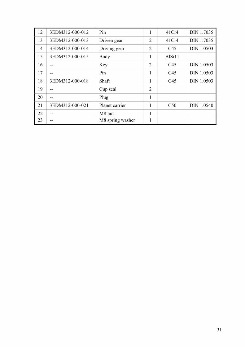
4.5 Mechanism specification& design №
item Designation Name No Material Note
1 3EDM312-000-001 Shaft 1 C45 DIN 1.0503 2 -- Key 2 C45 DIN 1.0503 3 3EDM312-000-003 Sprocket 2 C45 DIN 1.0503
4 -- М6х10 screw 2 5 3EDM312-000-005 Cap 2 AlSi11 6 -- М 6х16 bolt 8
7 -- Nut 2 8 -- 33 205 bearing 4 9 -- Stop clip ring 4
10 3EDM312-000-010 Cover 1 AlSi11 11 -- М6х16 bolt 8
31
12 3EDM312-000-012 Pin 1 41Cr4 DIN 1.7035 13 3EDM312-000-013 Driven gear 2 41Cr4 DIN 1.7035
14 3EDM312-000-014 Driving gear 2 C45 DIN 1.0503 15 3EDM312-000-015 Body 1 AlSi11 16 -- Key 2 C45 DIN 1.0503
17 -- Pin 1 C45 DIN 1.0503 18 3EDM312-000-018 Shaft 1 C45 DIN 1.0503 19 -- Cup seal 2
20 -- Plug 1 21 3EDM312-000-021 Planet carrier 1 C50 DIN 1.0540 22 -- М8 nut 1 23 -- M8 spring washer 1

32

33

34

35

36

37

38

39

40

41

42

43

44

45
References
1. A. Bracci, M. Gabiccini, A. Artoni, M. Guiggiani, Geometric contact pattern estimation for gear drives. Computer Methods in Applied Mechanics and Engineering, Volume 198, Issues 17-20, 15 April 2009, Pages 1563-1571.
2. R Keith Mobley, Gears and Gear Drives.Plant Engineer's Handbook, 2001, Pages 57/1029-57/1042.
3. The generation principle and mathematical models of a novel cosine gear drive. Mechanism and Machine Theory, Volume 43, Issue 12, December 2008, Pages 1543-1556.Shanming Luo, Yue Wu, Jian Wang.
4. Cheng-Kang Lee, Manufacturing process for a cylindrical crown gear drive with a controllable fourth order polynomial function of transmission error. Journal of Materials Processing Technology, Volume 209, Issue 1, 1 January 2009, Pages 3-13.
5. Szu-Han Wu, Shyi-Jeng Tsai, Contact stress analysis of skew conical involute gear drives in approximate line contact. Mechanism and Machine Theory, Volume 44, Issue 9, September 2009, Pages 1658-1676.
6. Faydor L. Litvin, Ignacio Gonzalez-Perez, Kenji Yukishima, Alfonso Fuentes, Kenichi Hayasaka, Design, simulation of meshing, and contact stresses for an improved worm gear drive. Mechanism and Machine Theory, Volume 42, Issue 8, August 2007, Pages 940-959.
7. L.V. Mohan, M.S. Shunmugam, Geometrical aspects of double enveloping worm gear drive. Mechanism and Machine Theory, Volume 44, Issue 11, November 2009, Pages 2053-2065.
8. Tengjiao Lin, H. Ou, Runfang Li, A finite element method for 3D static and dynamic contact/impact analysis of gear drives. Computer Methods in Applied Mechanics and Engineering, Volume 196, Issues 9-12, 1 February 2007, Pages 1716-1728.
9. D. Richards, D. J. Pines, Passive reduction of gear mesh vibration using a periodic drive shaft. Journal of Sound and Vibration, Volume 264, Issue 2, 3 July 2003, Pages 317-342.
10. Li Ting, Pan Cunyun, On grinding manufacture technique and tooth contact and stress analysis of ring-involute spherical gears. Mechanism and Machine Theory, Volume 44, Issue 10, October 2009, Pages 1807-1825.
11. I. H. Seol, F. L. Litvin, Computerized design, generation and simulation of meshing and contact of worm-gear drives with improved geometry. Computer Methods in Applied Mechanics and Engineering, Volume 138, Issues 1-4, 1 December 1996, Pages 73-103.
12. F.L Litvin, M.De Donno, A Peng, A Vorontsov, R.F Handschuh, Integrated computer program for simulation of meshing and contact of gear drives. Computer Methods in Applied Mechanics and Engineering, Volume 181, Issues 1-3, 7 January 2000, Pages 71-85.

46
13. Biing-Wen Bair, Chung-Biau Tsay, Effects of profile shifted factor and pressure angle on the ZK-type dual-lead worm gear drives. Journal of Materials Processing Technology, Volume 112, Issue 1, 3 May 2001, Pages 29-36.
14. Biing-Wen Bair, Computer aided design of elliptical gears with circular-arc teeth. Mechanism and Machine Theory, Volume 39, Issue 2, February 2004, Pages 153-168.
15. Illés Dudás, Main operating charac teristics and quality assessment of worm gear drives. The Theory and Practice of Worm Gear Drives, 2004, Pages 260-288.
16. Faydor L. Litvin, Alfonso Fuentes, Matt Howkins, Design, generation and TCA of new type of asymmetric face-gear drive with modified geometry. Computer Methods in Applied Mechanics and Engineering, Volume 190, Issues 43-44, 17 August 2001, Pages 5837-5865.

47
CHAPTER 5 Local Bending Stresses in Axi-Symmetrical Thin
Shells for Storing Pressure Vessels
5.1 Introduction The engineering applications of thin shells include storage tanks for liquids or solids and pressure vessels for a variety of chemical processes. “Thin” is a relative term which indicates that the thickness of the material is small compared with the overall geometry, a ratio of 10:1 or greater being the usual criterion. Whenever there is a change in geometry of the shell, particularly for discontinuities in the meridian, the membrane stresses cause displacements which give rise to local bending in the wall. The resulting bending stresses may be significant in comparison with the membrane stresses (Calladine, 1989). This is the reason for introducing most of the times a reinforcing ring in the above problem.
In most cases storage tanks for fluids equalise air pressure in compressor stations. Tanks are usually made with a cylindrical body and convex bottoms (Andrade, 1998). In some cases, the filler neck, the manometer reading the pressure within the tank and the outlet pipe flange are mounted on the cylindrical section. A safety valve (upper bottom section) and a release valve (lower bottom section) were mounted on the bottom sections of the tank.
In current article cylindrical vessels with hemispherical ends of the same thickness, subjected to internal pressure will be considered in order to analyze the method of local bending. The design of thin shells depends primarily on the magnitude of the general system of membrane stresses. However, attention must also be given to the effect of local bending stresses at regions of discontinuity in the shell. These stresses are of the same order of magnitude as the membrane stresses, but they decay rapidly with distance from the discontinuity in thin walled shells (Khabakhpasteva, 2009). Surprisingly, reinforcement of a shell with rigid stiffeners increases the stress in a shell due to local bending.
In practise continuum elements, which can model a quadratic variation in displacement or a linear variation in stress are usually preferred. These may be triangular or quadrilateral in shape for plane stress analysis (Opoka, 2004). A further advantage of this type of element is that it can have curved sides to approximate curved boundaries. Plane shell elements are being used such as the constant quadrilateral to allow the analysis of loading in the thin sheet curved material (Bathe, 1982).
5.2 Aluminium Small Capacity, Highly Pressurized Shell
5.2.1. Material selection
Material’s chemical composition
To ensure minimum weight of the pressurised container being designed the high-strength aluminium alloy ALZN6MG2 has been selected having the chemical composition in Table 1 (Ashby, 1992):

48
Table 1 ALZN6MG2 chemical composition
Alloy Al Cu Mg Mn Fe Si Zn Cr
AlZn6Mg2 Basic 1.4 - 2 1.8 - 2.8 0.2- 0.6 <0.5 <0.5 5.0-7.0 0.1-0.2
Mechanical material characteristics The selected aluminium alloy features relatively high and close values of the temporary resistance σB and conditional yield strength σY. A considerable increase of plastic properties, cracks and corrosion resistance is exhibited during the coagulation stage ageing, with the material usually used for high relative strength and heavy-duty constructions. The mechanical characteristics of the selected alloy are shown in Table 2 (Osgood, 1994):
Table 2 ALZN6MG2 mechanical characteristics ρ E G σB σ Y δ
kg/m3 MPa MPa MPa MPa %
2850 72000 27000 570 500 8 where ρ is the mass density, E is the Young’s modulus, G is the modulus of rigidity and δ is the residual deformation after destruction.
5.2.2. Thin-wall cylinder theory: Strength calculations & dimensioning
Geometry and weight The basic dimensions and geometric parameters of the designed vessel in Figure 1 were: the capacity V = 0.3 m3; the cylindrical section length L, m; the wall thickness t, m; the middle surface diameter d, m and the middle surface area S, m2. The capacity of the tank expressed using its geometrical dimensions is the following (Young, 1989):
( ) ( )V
d tL
d t=
−+
−=π π
2 3
4 60 3, (1)
The middle surface area has been calculated using the relationship:
S dL d= +π π 2 (2)
The weight of the vessel was
m St= ρ (3)
Fig. 1. Geometrical dimensions and stressed state of the vessel’s wall
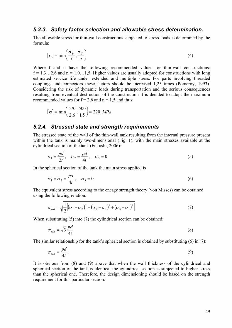
49
5.2.3. Safety factor selection and allowable stress determination. The allowable stress for thin-wall constructions subjected to stress loads is determined by the formula:
[ ]σσ σ
=⎛⎝⎜
⎞⎠⎟min ,B Y
f n (4)
Where f and n have the following recommended values for thin-wall constructions: f = 1,3…2,6 and n = 1,0…1,5. Higher values are usually adopted for constructions with long estimated service life under extended and multiple stress. For parts involving threaded couplings and connectors these factors should be increased 1,25 times (Pomeroy, 1993). Considering the risk of dynamic loads during transportation and the serious consequences resulting from eventual destruction of the construction it is decided to adopt the maximum recommended values for f = 2,6 and n = 1,5 and thus:
[ ]σ =⎛⎝⎜
⎞⎠⎟
=min,
,,
5702 6
5001 5
220 MPa
5.2.4. Stressed state and strength requirements The stressed state of the wall of the thin-wall tank resulting from the internal pressure present within the tank is mainly two-dimensional (Fig. 1), with the main stresses available at the cylindrical section of the tank (Fukushi, 2006):
tpd21 =σ ,
tpd42 =σ , 03 =σ (5)
In the spherical section of the tank the main stress applied is
tpd421 == σσ , 03 =σ . (6)
The equivalent stress according to the energy strength theory (von Misses) can be obtained using the following relation:
( ) ( ) ( )[ ]213
232
2212
1 σσσσσσσ −+−+−=red (7)
When substituting (5) into (7) the cylindrical section can be obtained:
tpd
red 43=σ (8)
The similar relationship for the tank’s spherical section is obtained by substituting (6) in (7):
.4tpd
red =σ (9)
It is obvious from (8) and (9) above that when the wall thickness of the cylindrical and spherical section of the tank is identical the cylindrical section is subjected to higher stress than the spherical one. Therefore, the design dimensioning should be based on the strength requirement for this particular section.

50
5.2.5. Dimensioning The strength requirement for the cylindrical section is given by Lessens (1996):
[ ]σ σred
pdt
= ≤34
(10)
into an equality from which d can be expressed:
[ ]d
tp
=4
3σ
(11)
And after substituting in (1) it is obtained:
at bt V3 2+ = (12)
where:
[ ]a
p= −
⎛
⎝⎜
⎞
⎠⎟
π σ6
43
13
[ ]
bp
L= −⎛
⎝⎜
⎞
⎠⎟
π σ4
43
12
(13)
Proceeding with the study of the influence of the cylindrical section length on the weight of the whole construction using the MathCad software in the following sequence:
1. Preset a number of values for L in the 0, 1…4 m range.
2. Using (12) calculate the t for the individual L values and decrease [σ] to 200 Mpa for the calculation of a and b.
The decision to reduce [σ] has been in view of the consideration that the indicated internal pressure within the tank is considerable and the actual construction will look closer to thick-wall cylinders and spheres. For such constructions the radial, circumferential and equivalent stresses in various locations on the interior surface for the internal pressure involved are higher than those defined based on the thin-wall cylinders and spheres theory (Li, et all., 2002).
3. The middle surface plane diameter can be determined from Eq. (11).
L, m
0.0 0.5 1.0 1.5 2.0 2.5 3.0 3.5 4.0
t, m
0.0150.0200.0250.0300.0350.0400.0450.0500.0550.060
L, m
0.0 0.5 1.0 1.5 2.0 2.5 3.0 3.5 4.0
d, m
0.3
0.4
0.5
0.6
0.7
0.8
0.9
Fig. 2. The relation between wall thickness and length of cylindrical section of the tank
Fig. 3. The relation between middle surface diameter and the length of the
cylindrical section

51
4. From (2) and (3) above the middle surface area, S and the weight of the overall construction, m can be determined.
L, m
0.0 0.5 1.0 1.5 2.0 2.5 3.0 3.5 4.0
S, m
2
2.0
2.5
3.0
3.5
4.0
4.5
L, m
0.0 0.5 1.0 1.5 2.0 2.5 3.0 3.5 4.0
m, k
g
240260280300320340360380400420
Fig. 4. The relation between the middle
surface area and the length of the cylindrical section
Fig. 5. The relation between the weight of the construction and the length of the
cylindrical section
Fig. 3 to 5 indicate that as the length of the cylindrical section increases the wall thickness and the middle surface diameter decrease and hence the middle surface area increases. The weight of the tank suddenly decreases for small L values and tends to a constant value for higher L. In this order of thoughts:
• The theory for determining the stressed state of thin-wall cylinders and spheres subjected to internal pressure has been applied for the above calculation and the actual construction has considerable wall thickness;
• The bending momentum occurring at the location of the transition between cylindrical and spherical casing of the tank and the stress it induced have been also examined;
• For small L values the construction can be regarded close to the perfect sphere body where the equivalent stress of Von Misses is √3 times lower compared to that for a perfect cylindrical body. Therefore, we could expect the wall thickness and the weight of the actual construction to be lower than those shown in Fig. 2 and 5.
Above discussions suggest that strength calculations based on the Finite Element Method (FEM) should be made for at least two different alternative constructions – for the smallest L value (100 mm as limited by the pre-set design requirements) with a reduced value of t compared to that shown in Fig. 2, and for a high L value from which the weight of the tank can further only change slightly. The geometrical dimensions of the two alternatives selected above are given in Table 3:
Table 3 Geometrical dimensions for the two alternatives
Alternative L (mm) t (mm) d (mm) m (kg)
V1 100 40 822 271,5
V2 1500 32 492 280,9

52
5.2.6. Strength and deformation calculations using the Finite Element Method (FEM)
5.2.6.1. Basic characteristics and relations of the finite element employed The nature of the construction suggests the use of an axially symmetric massive finite element with an axially symmetric load applied to it. Fig. 6 shows one such finite element having a rectangular shape of its meridian section, eight node circles and two degrees of freedom per node (the cross point between the meridian section and the node circle) – u1 and u2. The displacements and coordinates in the finite element area were approximated using the same functions - isoparametric finite element (Szwabowicz, 2004):
u h ui k ik
k=
=∑
1
8
, x h xi k ik
k=
=∑
1
8
, (14)
where:
( )( )( )h1 1 2 1 2
14
1 1 1= + + + −ξ ξ ξ ξ , ( )( )h5 12
2
12
1 1= − +ξ ξ
( )( )( )h2 1 2 1 2
14
1 1 1= − + − + −ξ ξ ξ ξ
( )( )( )h3 1 2 1 2
14
1 1 1= − − − − −ξ ξ ξ ξ ( )( )h7 12
2
12
1 1= − −ξ ξ
( )( )( )h1 1 2 1 2
14
1 1 1= + − − −ξ ξ ξ ξ ( )( )h8 1 221
21 1= + −ξ ξ
are the approximation functions from the second degree syrendipic class. In these functions ξ1
and ξ2 are the natural coordinates, which vary within the [-1,1] interval range.
The square parabolic approximation of shifts involved in this particular finite element allows achieving satisfactory degree of accuracy for networks having a smaller number of larger finite elements (Timoshenko, 1970).
2
6
5
7
4
1
8
3
x2
x1
u1
u2
Fig.6. Axially symmetric massive rectangular isoparametric finite element featuring two
degrees of freedom (Flores, 2007)

53
The node shift vector comprises the shifts of all eight nodes arranged in the following order:
[ ]u T u u u u u u= 11
211
12
22
18
28. . . . (15)
The stress and deformation vectors in the three-dimensional stressed state are expressed as follows:
[ ]σ =Τ11 22 12 33σ σ σ σ (16)
[ ]ε Τ = ε ε ε ε11 22 12 33 (17)
where σ11 is the normal stress in the radial direction; σ22 is the normal stress in the axial direction; σ33 is the normal stress in the tangential (circumference) direction, σ12 is the tangential stress in the areas having normals in the radial and axial direction and εij are linear and angular deformations, respectively.
The shifts and deformations are related to the following relations:
ε∂∂11
1
1=
ux
, ε∂∂22
2
2=
ux
, ε∂∂
∂∂12
2
1
1
2= +
ux
ux
, ε 331
1=
ux
, (18)
which can be expressed in a matrix recording as follows:
ε = Bu (19)
B is the matrix that determines the relations between deformations and angular shifts in a matrix form and is expressed as:
B =
⎡
⎣
⎢⎢⎢⎢⎢⎢
⎤
⎦
⎥⎥⎥⎥⎥⎥
h h hh h h
h h h h h hhx
hx
hx
1,1 2 1 8 1
1,2 2 2 8 2
1,2 1,1 2 2 2 1 8 2 8 1
1
1
2
1
8
1
0 0 00 0 0
0 0 0
, ,
, ,
, , , ,
. . .
. . .
. . .
. . .
(20)
hhxk j
k
j, =
∂∂
, x h xè kk
k=
=∑ 1
1
8
, (21)
where x1k are the components of the node coordinates vector
[ ]xT x x x x x x= 11
21
12
22
18
28. . . . , (22)
and hk , k = 1…8 are the approximation functions.
The relationships between stress and deformations expressed in a matrix form for linear plastic materials can be determined based on the summarized Hooke’s law (Tomczyk, 2007)for the axially symmetrical stressed state expressed as:
σ ε= C , (23)
where C is the matrix of material constants

54
( )( )( )
( )
C =−
+ −
− −
−−
−
⎡
⎣
⎢⎢⎢⎢⎢⎢⎢⎢
⎤
⎦
⎥⎥⎥⎥⎥⎥⎥⎥
E
symm
1
1 1 2
11
01
1 01
1 22 1
0
1
μ
μ μ
μμ
μμ
μμ
μ
μ.
, (24)
E is the Young’s modulus and μ is the Poisson’s coefficient. The relationship between the forces applied to the finite element nodes and their shifts is expressed by:
Ku R= , (25)
Where:
K B CBT= ∫ dVV (26)
is the rigidity of the finite element matrix, and
[ ]RT = R R R R R R11
21
12
22
18
28... (27)
is the node forces vector. The statically equivalent node forces for a preset surface-distributed load can be determined by:
R H pT
S
= ∫ ds (28)
5.2.6.2 Finite element model of the pressurized container
Network geometry The tank wall has been digitized using two layers of finite elements having a meridian section shape very close to the square, as described in Fig. 7. For alternative V1 the network comprised 122 finite elements and 493 nodes and for alternative V2 – 280 finite elements and 1123 nodes.

55
a) Alternative V1 b) Alternative V2
Fig. 7. Two alternative tank geometric dimensions networks
Supports Nodes from the bottom hemisphere lying on the axis of symmetry x2 should not be shifted in the x1 direction. Nodes from the external surface in the middle of the cylindrical section should not be shifted in the x2- direction.
Load Load is set in the internal surface nodes as a normal surface load having an intensity of p = 30 Mpa and directed opposite to the external normal at the finite elements boundary from the interior layer.
Material characteristics The material is assumed to be linear elastic and having the elastic characteristics in accordance with Table 2. The allowed stress value is set to a value of [σ] = 220 Mpa.

56
5.3 HSS Large Capacity, Low Pressure Loading Tank
Calculations
Determining the length of the cylindrical section of the tank. The length of the cylindrical section of the tank is determined using the cylinder volume capacity equation
;.4. 2
LDV π=
hence:
2..4DVL
π= (29)
The volume capacity of the cylinder is:
V = V1 - 2 V2 = 0.6 – 2 . 0,2618 . D3 (30)
where V1 = 0.6m3 is the total tank capacity, and V2 is the bottom section volume capacity. This is regarded as a hemi-sphere and its volume capacity is calculated by the equation:
33 2 .2618.0.
12V DD ==
π
Therefore, the length of the cylinder can be obtained for:
2
3
.).2618.06.0(4
DDL
π−
= (31)
The L cannot have a negative value or equal to zero and the same is true for the D as well. Therefore, for which D values L>0, is left to be found. Considering only the numerator of eqn. (31).
0.6 – 2 . 0.2618 . D3 >0 (32)
35236.0
6.0<D
or D < 1.046 m (33)
Substituting in the formula for L the minimum possible length for the cylindrical section of the tank will be thus obtained:
mD
DL 001.0931,1.14,3
)046,1.5236,06,0(4.14,3
).5236,06,0(42
3
2
3
=−
=−
=
Therefore, this particular tank will not incorporate any cylindrical section, having the shape of a sphere. However, the initial assignment data is that for L = 100mm = 0.1m. When substituting it in equation (3) the following equation for the cylinder diameter can be obtained:
6.0.0785,0.5236,0 23 =+ DD m3
Solving this equation comes up with the following value for the cylindrical section diameter:
D = 0.998 m

57
The Fig. 8 diagram shows the results for the relation between the cylindrical section tank diameter and its length.
Fig. 8. Length - diameter for constant tank capacity
Selecting the material for the tank The following material brands have been recommended for the tank contents:
Table 4
Boiler steel brands:
St 34-2 σB = 330 MPa St 37-3 σB = 370 MPa St 44-3 σB = 420 MPa
High-strength steel brands:
10Mn4 σB = 490 MPa
A safety factor of n = 4.25 has been assumed for tanks with internal pressure p>0.7 MPa and pressurised gas containers for pressure values above 1.5 Mpa.n = 4 for all other pressurised tanks. Above safety factor values relate to tanks operating at temperatures under 100°K. The allowable tensile strength can be determined using the formula:
[ ]n
Bσσ =
Where σB is the tensile strength of the basic material measured in MPa. Thus for Boiler steel and High-strength steel brands Table 5 allowable tensile strength data is obtained.

58
Table 5
Boiler steel brands:
St 34-2 [σ ] = 82.5 MPa St 37-3 [σ ] = 92.5 MPa St 44-3 [σ ] = 105 MPa
High-strength steel brands:
10Mn4 [σ ] = 122 MPa
Determining the cylinder wall thickness. The thickness of the wall of the cylinder is determined using the formula:
310.].[.2
. −=σϕ
δ DP ,m
where p = 100 105 Pa is the pressure inside the tank; D is the internal diameter of the tank, mm. The thickness of the cylinder wall is dependent on [σ ] and the higher this value the smaller the wall thickness, turning the tank unstable. It is recommended that the wall thickness is increased by c = 1-3 mm, the material ageing factor, which accounts for corrosion, and deformations.(Li, et all., 2002)
mDP 310).31].[.2
.( −÷+=σϕ
δ
ϕ = 0.85 is the strength coefficient for butt weld seams. The obtained results for the tank wall thickness values are shown in Table 6.
Table 6 Pressure vessel Thickness
Determining the bottom sections wall thickness
The wall thickness of the bottom sections of the tank is determined using the formula:
[ ] 31 10.31.
].[2. −÷+= yDPσ
δ

59
[ ]n
Bσσ =
is the allowed tensile stress for bottom sections operating at temperatures not less than 100° C; y – is the bottom section shape factor, which is dependent on the relation h/D; h – is the height of the convex section of the bottom, i.e.:
5.021
2
,2
==
=
=
Rh
RButhRh
Dh
According to the table h/D = 0.5 corresponds to y = 0.75 and
h = 0.75.D
The data for the bottom section wall thickness is shown in Table 6. Taking into account the transportation limitations, i.e. the max. height of the off-gauge load should not be larger than 3 meters, then the total tank length will be:
L1 = L + 2R2 + C1
2R2 = D2 ,
Where, L is the length of the cylindrical section of the tank; D2 is the external diameter of the hemisphere; Based on the results presented in Fig. 8 and Table 6, several suitable tank alternatives could be selected to be made. From strength considerations (Tables 1 and 2) and results shown in Table 6, a tank to be manufactured of Steel 10Mn4 has been selected in Fig 9.
Fig. 9 The Steel 10Mn4 tank
Determining the weight of the tank
All data presented so far could be used to calculate the weight of the tank when it is not under pressure. I shall consider it comprises 2 hemispheres and a cylindrical section:
V = V1 + 2V2
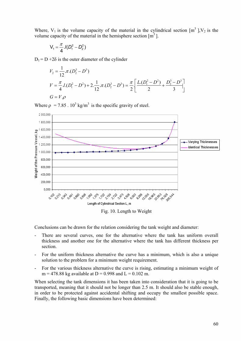
60
Where, V1 is the volume capacity of the material in the cylindrical section [m3 ],V2 is the volume capacity of the material in the hemisphere section [m3 ].
)(.4
V 22
211 DDl −=
π
D1 = D +2δ is the outer diameter of the cylinder
ρ
πππ
π
.32
).(.2
).(.121.2).(.
4
).(.121
332
22133
222
1
3322
VG
DDDDLDDDDlV
DDV
=
⎥⎦
⎤⎢⎣
⎡ −+
−=−+−=
−=
Where ρ = 7.85 . 103 kg/m3 is the specific gravity of steel.
Fig. 10. Length to Weight
Conclusions can be drawn for the relation considering the tank weight and diameter:
- There are several curves, one for the alternative where the tank has uniform overall thickness and another one for the alternative where the tank has different thickness per section.
- For the uniform thickness alternative the curve has a minimum, which is also a unique solution to the problem for a minimum weight requirement.
- For the various thickness alternative the curve is rising, estimating a minimum weight of m = 478.88 kg available at D = 0.998 and L = 0.102 m.
When selecting the tank dimensions it has been taken into consideration that it is going to be transported, meaning that it should not be longer than 2.5 m. It should also be stable enough, in order to be protected against accidental shifting and occupy the smallest possible space. Finally, the following basic dimensions have been determined:
61
- weight 1022.893 kg
- internal diameter 0.600 m
- length of cylindrical section 1.722 m
- cylindrical section wall thickness 0.030 m
- bottom sections wall thickness 0.020 m
-
Longitudinal section stress The internal pressure tends to force the cylinder to break in two sections, the longitudinal and the cross section. When considering the stress occurring into the longitudinal, the assumption for the bottom sections being removed. The force ΔF is a radial force and is acting on an elementary small area ΔS. The force
yx FFFrrr
Δ+Δ=Δ
Although, ΔF = P . ΔS. With the shear force obtained in .
lDPN .2.
=
The product P.D is the clamping area.The stress occurring at the longitudinal section is:
][2. σδ
σ ≤=DP
From the above formula the larger the diameter of the cylinder, the higher will be the stress for identical pressure and cylinder thickness values. Consequently, tanks intended for highly pressurised fluids are made to have small diameters.
PaMPa 665
10.122][10.100030,0.2
6,0.10.100=<== σσ
The pressure applied on the bottom of the tank is calculated from equation:
4..
2DPF π=
This force subjects the hemisphere (the bottom section) to tension. The bottom section can be regarded as a ring having an interior diameter D and δ1 thickness. The area of the ring is
S = π.D.δ1 .
Hence the stress is obtained for:
][.4..
1
σδ
σ ≤=DP
PaPa 655
10.122][10.75020,0.4
6,0.10..100=<== σσ
From the strength calculations, the operational stress in the cylindrical and bottom sections of the tank are lower than the allowable ones. Therefore, the selected from the table data is suitable for the purpose. Also, the stress in the longitudinal section is higher than that in the

62
cross section. Thus, attention should be paid to the length of weld seams. Modern techniques provide opportunities to make seamless pipes of various diameters (Zhang, 2003).
Fig. 11 Design layout of the tank
Strength calculations of seams connecting the cylindrical tank section to the bottom sections
The strength of the weld seams is dependent on the interpenetration between the added melted material (the electrode) and the material of the elements being welded. Material melting should occur in a depth of 1,5 - 3mm. If the 3mm maximum depth is exceeded this results in material overheating, which reduces its toughness. According to material thickness tables (Mathon, 2006) materials thicker than 8 mm are recommended to be chamfered at an angle of 60° ± 5°.
Fig. 12 Weld seams connecting the cylindrical tank section to the bottom
The strength of the weld seams is dependent on the type of electrodes employed, the material of the elements being welded together and the quality of the welding. The allowed stress in the weld seams is assumed to be lower than the stress for the materials being welded. For the 10Mn4 material a stress of [σ] = 1450.105 Pa and an electrode ∋42 are recommended. Weld seams are subjected to tension as a result of the internal pressure of the fluid within the tank.
][σσ <=FP
P = 100 . 105 Pa is the pressure of the fluid contained in the tank
F = π . D’ . h
D’ = D + 1÷3 (from Figure 3)
D’ = 600 + 2÷6 = 602 ÷ 606. I assume D’ = 606 mm.
And h = 20 mm is the weld seam height (3 mm seam protrusion).

63
As there are two weld seams involved the pressure shall be uniformly distributed between them. Therefore, the stress formula will be expressed as:
PaPaDP 55
5
10.1450][10.8,131302,0.606,0.14,3.2
10.100]'.[..2
=<=== σσπ
σ
The weld seam is strong enough to withstand the required load, it could either be made as a multi-layer seam or welding under a layer of flux.
5.4 Discussion
5.4.1. Aluminium small capacity, highly pressurized shell: finite element calculation results
Node shifts The maximum increase of the cylindrical section radius resulting from the deformation in alternative V1 occurs in its middle section and is 0.9364 mm and the increase of its axial dimension is 1.008 mm. For alternative V2 the absolute variations of dimensions are lower. The maximum increase of the cylindrical section radius occurs close to the spherical section transition and is 0.2082 mm. Otherwise, this radius variation for locations away from the spherical section transition is almost constant and the axial dimension increase is 0.3684 mm.
Figure 13a shows the non-deformed and deformed network for both alternatives discussed here, the comparison suggesting that the alternative V2 deformation is more uniform in nature.

64
a) Alternative V1 b) Alternative V2
Fig.13. a). Non-deformed (before the applied load) and b).deformed state(subsequent to the applied load). Shifts have been magnified 130 times.
Stress analysis Figures 14, 15 and 16 show the equivalent stress diagrams determined at the exterior, interior and middle surface planes in accordance with Von Misses energy theory for alternative V1. These are almost constant in the spherical section of the exterior surface (Fig. 14) increasing in the transition between the spherical and cylindrical section, and rissing to the maximum at the middle of the cylindrical section. Two local extremums (Fig. 15) were observed in the exterior surface of the transition area between the cylindrical and spherical sections. The equivalent stress at the middle surface plane (Fig. 16) of the spherical sections is constant and increases in the transition reaching its maximum in the cylindrical section middle. The maximum equivalent stress is acting on the cylindrical middle section at the exterior surface.
Stress concentration is observed in the pipe connection opening area and this has a strictly local nature (in the interior surface) and does not represent any hazard for plastic materials.

65
Fig. 14. Equivalent stress distribution determined in accordance with Von
Misses’s theory for the exterior surface of Alternative V1
Fig. 15. Equivalent stress distribution determined in accordance with Von Misses’s theory for the interior surface of Alternative
V1
Fig. 16. Equivalent stress distribution determined in accordance with Von
Misses’s theory for the middle surface of Alternative V1.
Fig. 17. Equivalent stress distribution determined in accordance with Von
Misses’s theory for the exterior surface of Alternative V2.

66
Fig. 18. Equivalent stress distribution determined in accordance with Von
Misses’s theory for the interior surface of Alternative V2
Fig. 19. Equivalent stress distribution determined in accordance with Von
Misses’s theory for the middle surface of Alternative V2.
Figures 17, 18 and 19 show the equivalent stress diagrams determined at the exterior, interior and middle surfaces according to the energy theory of Von Misses for alternative V2.
Two local extremums of equivalent stress can be observed in the exterior (Fig. 17), interior (Fig. 18) and middle surface (Fig. 19) in the area of transitions between the spherical and cylindrical section. The equivalent stress value decreases in the spherical sections and the cylindrical section is uniformly loaded. From the comparison between the two alternatives it is obvious that for the V2 alternative the larger material amount is uniformly loaded with stress, which is close to the allowed values. Stress concentration in the pipe opening area is also less in amount. Therefore, we can expect lower construction weight for longer cylindrical sections.
Figures 20 through 23 show the directions of major stresses occurring in the meridian section for both alternatives both in the pipe opening area (Fig. 20 and 22) and the spherical to cylindrical transition area (Fig. 21 and 23). From these figures one of the three major stresses is in the radial direction and another one is in the tangential. The radial major stress is a pressure stress and the tangential one is a tension stress. The third major stress is in the circumferential direction and is a tension stress.

67
Fig. 20. Major stress directions in the
meridian section in the pipe opening area for Alternative V1
Fig. 21. Major stress directions in the meridian section in the transition area between the spherical and cylindrical
section for Alternative V1.
Fig. 22. Major stress directions in the
meridian section in the pipe opening area for Alternative V2
Fig. 23. Major stress directions in the meridian section in the transition area between the spherical and cylindrical
section for Alternative V2
5.4.2. HSS large capacity, low pressure loading tank: finite element calculation results
Node shifts The maximum increase of the cylindrical section radius occurs close to the transition to the spherical section and is 0.1284 mm. Otherwise, this radius variation for locations away from the cylindrical section transition is almost constant and equal to 0.1272 mm and the axial dimension increase is 0.2877 mm. Figure 24 shows the non-deformed and deformed network.

68
Stress analysis Figures 25, 26 and 27 show the equivalent stress diagrams determined at the exterior, interior and middle surface planes in accordance with the energy theory of Von Misses. Two local maximums of the equivalent stress can be observed in the exterior surface in the area of transitions between the cylindrical and spherical sections, which is a result of the stress concentration from the transition between the two surfaces. Away from the transition locations the cylindrical and spherical sections are almost uniformly loaded and the equivalent stress value is higher in the cylindrical section. The maximum equivalent stress is observed in the locations on the interior surface plane. Stress concentration in the pipe union opening area is rather obvious, having a strictly local nature.
Figures 28 and 29 show the directions of major stresses occurring in the meridian section both in the pipe opening area (Fig. 28) and the spherical to cylindrical transition area (Fig. 29). In these figures one of the three major stresses is in the radial direction and another one is in the tangential direction. The radial major stress is a pressure stress and the tangential one is a tension stress. The third major stress is in the circumferential direction and is a tension stress.
Fig. 24. Non-deformed (before the load is applied) and deformed (after the load is
applied) state. Shifts have been magnified 130 times
Fig. 25. Equivalent stress distribution determined in accordance with von Mises’s
theory for the exterior surface for Alternative V1

69
Fig. 26.. Equivalent stress distribution determined in accordance with von Mises’s
theory for the interior surface for Alternative V1
Fig. 27. Equivalent stress distribution determined in accordance with von
Mises’s theory for the middle surface for Alternative V1
Fig. 28. Major stress directions in the meridian section in the pipe opening area for
Alternative V1.

70
Fig. 29. Major stress directions in the meridian section in the transition area between the
spherical and cylindrical section for Alternative V1.
5.5. Selecting Acid-Resistant Materials
5.5.1 Introduction Accumulated statistics show that worldwide annually around 30% of all metal constructions become useless as a result of damages caused by corrosion. Corroded metal equipment is taken out of operation and subjected to processing in corresponding metallurgy plants. A certain part of metal equipment is subjected to electro chemical corrosion in electrolytic (so-called corrosive) medium. Included here are tanks designed for storage of acids, bases, salts, etc., which are subjected to electrolytic corrosion as they are surrounded by an electrolytic medium. Nowadays, there are multiple possibilities to fight corrosion effectively. There are some measures to protect metal constructions that should and must be taken from the very

71
design phase of the metal equipment by selecting the suitable material. Depending on the conditions and properties of the medium that the metal equipment is going to be subjected to various brands of steel and alloys having the appropriate corrosion resistance should be used to make it reliable and inexpensive. This task is covered by the present assignment of selecting materials for storing diluted sulphuric acid and hydrochloric acid (10 % w/w).
5.5.2 Anodic passivation It was M.V.Lomonosov (1738) and later Bertselius and M.Faraday that described the paradoxical fact that iron easily dissolves in diluted nitric acid solutions but this process continues only until acid concentration is increased. Faraday explained this by the formation of a protective oxide layer on the iron surface, which prevents the metal from dissolving further. The process of bringing metals to a condition of increased resistance when subjected to various oxidising agents is called passivation. With all the practical application possibilities that this phenomenon offers, namely for fighting metal corrosion, it has been the target of multiple and comprehensive studies ever since it was initially discovered.
In addition to being subjected to oxidising agents metals could also be passivated by means of anodic polarization, i.e. by using electric current to divert the equilibrium potential of the electrode in the positive direction. In this case we talk about anodic passivation.
Modern studies on anodic passivation of metals run basically in two main directions. On one side, the mechanics of the processes leading to changes in the condition of the metal surface and bringing the metal into stable (passive) state are investigated and the nature and morphology of oxidised layers thus formed are studied, on the other.
5.5.3 Mechanics of anodic passivation Dependent on the nature of the solution and the value of diversification of electrode potential in the positive direction metal passivation could take place in different ways. In active anodic dissolving of metals there may be a point of saturation of the electrolyte with respect to certain metal salts, thus forming a solid product that can be deposited on the surface of the metal. If the apparent current density is maintained constant then the actual current density in the areas accessible for the electrolyte will increase as a result of the shield formed on the electrode surface by the deposited non-conductive solid product. The potential in these areas strongly diverts into the positive direction, which makes it possible for a thermodynamic reaction to take place and formation of a hard metal oxide or hydroxide. The oxide layer thus formed on separate areas eventually spreads on the entire metal surface preventing it from dissolving further.
Also outstanding are V.Muller’s (1933) trials that subjected iron, zinc, copper, etc. metal electrodes horizontally positioned in the electrolyte to anodic polarization in diluted sulphuric acid solutions. The polarized light studies have indicated that when there is no motion in the electrolyte hydrated sulphates of corresponding metals deposit on the surface of the electrodes. Once these salts are formed metals transform into their passive state.
Anodic passivation of metals could also be carried out without the formation of the shielding solid products. If no anions are present in the electrolyte to precipitate the metal cations that have entered the solution and if the potential of the electrode has been sufficiently diverted into the positive direction to allow for a reaction to take place, then a new phase of metal oxide or hydroxide is directly deposited on the metal surface, which changes the properties of

72
the initial metal surface and the nature of the anodic reaction. Under such conditions the metal stops to dissolve measurably and transfers into passive state.
Theories of passivity of metals. Wide practical applications uncovered by metal passivation have enhanced not only applications studies in this area but also investigations involving the nature of the processes taking place in this phenomenon. A large number of hypothesis were made with regards to the mechanism of passivation and the nature of the passive state of metals. Various concepts of above issues could be classified into two basic groups. One of the groups, the smaller one, comprises the concepts according to which the passivation phenomenon is the result of a number of changes taking place in the physical properties of the metal itself (for example, the change in the electron state of the metal and its transformation into a specific, chemically inactive allotropic state). Another group of theoretical concepts links passivation to the formation of protective oxide layers on the metal surface. The metal does not become thermodynamically nobler during passivation but transfers into a stable state thanks to the protective layers formed on its surface, which significantly change the electrochemical properties of the metal-medium interface. And if the discussions on the issue of the passive state of metals still continue to be fierce they are mainly concentrated on the question: what is the nature of these protective layers? Are these two-dimensional layers of adsorbed oxygen that block the metal surface making it inactive (the adsorption theory) or these are three-dimensional oxide layers, which under the form of a separate phase cover the metal surface and purely mechanically prevent it from the actions of the corrosive medium (the phase theory).
On the modern stage of development of our concepts of the mechanism of passivation and the nature of the passive state the widest popularity has the phase theory the basic ideas of which were stipulated by M.Faraday (1836). U.Evans gave direct experimental proof in support of these theoretical conceptions. He succeeded to separate from the surface of passivated iron some oxide layers and examined them directly under the microscope.
5.5.4 Experimental studies – anodic protection of mild steel in sulphuric acid solution
Experimental setup. The apparatus consists of a simple support for suspending two electrodes made of mild steel strip into a 600 ml beaker containing approx. 400 ml acid. The current supply is from a stabilized power supply source.
The current and voltage values could be measured using the power source devices and a multimeter. We increase the voltage in 0.1V intervals up to maximum 3.0V and we measure the current value for every voltage increase. Before we take down its value we wait for the current to stabilize. The current readings increase steadily up to the point where the passive section is reached when it suddenly drops. When 3.0V is reached we reduce the current through 0.1V intervals to see if there are some hysteresis effects. We repeat the experiment adding to the acid a small quantity of concentrated brine solution. We plot the voltage variation in relation to current density logarithm and we analyse the results.
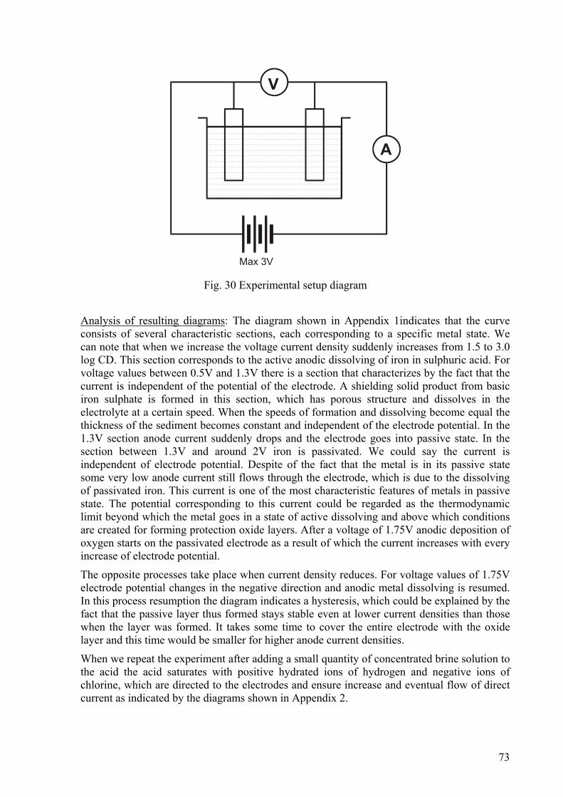
73
Analysis of resulting diagrams: The diagram shown in Appendix 1indicates that the curve consists of several characteristic sections, each corresponding to a specific metal state. We can note that when we increase the voltage current density suddenly increases from 1.5 to 3.0 log CD. This section corresponds to the active anodic dissolving of iron in sulphuric acid. For voltage values between 0.5V and 1.3V there is a section that characterizes by the fact that the current is independent of the potential of the electrode. A shielding solid product from basic iron sulphate is formed in this section, which has porous structure and dissolves in the electrolyte at a certain speed. When the speeds of formation and dissolving become equal the thickness of the sediment becomes constant and independent of the electrode potential. In the 1.3V section anode current suddenly drops and the electrode goes into passive state. In the section between 1.3V and around 2V iron is passivated. We could say the current is independent of electrode potential. Despite of the fact that the metal is in its passive state some very low anode current still flows through the electrode, which is due to the dissolving of passivated iron. This current is one of the most characteristic features of metals in passive state. The potential corresponding to this current could be regarded as the thermodynamic limit beyond which the metal goes in a state of active dissolving and above which conditions are created for forming protection oxide layers. After a voltage of 1.75V anodic deposition of oxygen starts on the passivated electrode as a result of which the current increases with every increase of electrode potential.
The opposite processes take place when current density reduces. For voltage values of 1.75V electrode potential changes in the negative direction and anodic metal dissolving is resumed. In this process resumption the diagram indicates a hysteresis, which could be explained by the fact that the passive layer thus formed stays stable even at lower current densities than those when the layer was formed. It takes some time to cover the entire electrode with the oxide layer and this time would be smaller for higher anode current densities.
When we repeat the experiment after adding a small quantity of concentrated brine solution to the acid the acid saturates with positive hydrated ions of hydrogen and negative ions of chlorine, which are directed to the electrodes and ensure increase and eventual flow of direct current as indicated by the diagrams shown in Appendix 2.
Fig. 30 Experimental setup diagram

74
Conclusions and practical applications. The results show that this experiment could be used for providing anodic protection of metals against corrosion. An oxidised layer covers metals when immersed into suitable oxidising medium (oxidation) or when used for a certain time as anodes in an electrolytic bath where their surface is oxidised by the oxide deposited on the anode (anodising).
5.5.5 Selecting materials for the tank Expensive special steels (£ 3 per kg). High-alloy steels are being produced for industrial, building and domestic applications, which are both corrosion resistant and fireproof. Corrosion resistant steels are capable of resisting the destructive chemical and electrochemical action of external environment. Considering steel’s ability to resist a certain aggressive corrosive medium it is classified as stainless, acid resistant and scale resistant. Acid resistant steel exhibits high corrosion resistance against the action of various aggressive mediums.
Corrosion resistant steels are usually chrome- or chrome-nickel alloys containing above 12% chrome. Depending on its chemical composition steels microstructure could be ferrite, semi-ferrite and allowing structural transformations, i.e. that can be subjected to improvements (above 15% carbon, 10% to 18% chrome) having austenitic structure.
High nickel and manganese steels feature extended areas of stable austenitic structure. When chrome-nickel steels are heated up to temperatures of 490 – 900 degrees or when being cooled down slowly in this interval chrome carbides are formed along the boundaries of the austenitic grains. This results in grains of rich in chrome and poor in carbon cores. As a result of this structural non-uniformity steel shows a tendency for inter-crystal corrosion. To avoid this drawback chrome-nickel steels have to be additionally alloyed using strong carbide-forming elements such as titanium and niobium.
The austenite structure of chrome-nickel and chrome-nickel-manganese steels renders these materials some very essential properties, such as non-magnetic characteristics, improved strength under high temperatures and good weldability.
Chrome-nickel steels usually acquire satisfactory strength and good plastic characteristics after being hardened with austenite. Strength characteristics of such steels can be improved by cold-work hardening by means of cold rolling, cold drawing or stamping. Cold-work austenite steel maintains sufficient plastic properties. Semi-finished products made of such steel could be bended, shaped or even stamped.
Selecting a high-alloy steel brand. For our application I select X5CrNiMoCuNb18 18 steel, which exhibits highest sulphuric and other acids resistance and finds wide application in the chemical industry. I am going to give the following most essential mechanical characteristics for this steel: the strength σB, the yield strength σS, the percentage of specific elongation δ, the percentage reduction of area ψ and impact strength aK. I will also apply the chemical composition, approximate forging and temperature treatment temperatures. The data is presented in the following tables:
Steel brand σS σВ δ ψ аK
ISO DIN МРа МРа % % KJ/m2
X5CrNiMoCuNb18 18 1.4505 230 750 40 35 650

75
Steel brand Content of elements in %
ISO DIN C Si Mn Cr Ni others
X5CrNiMoCuNb18 18 1.4505 <0,07 <1,0 <2,0 16,5-18,5
16,5-18,5
Mo=2,0-2,5Cu=1,8-2,2Nb>8x%C
Steel brand Forging Hardening
ISO DIN Temp. Coolant
Annealing negative
Temp. Coolant
Tempering
X5CrNiMoCuNb18 18 1.4505 1150-750
air - 1050-1100
water -
Low-cost steels (£ 1 per kg). Good quality carbon steel is intended for the needs of all machine-building industry areas. Parts made of this type of steel are usually subjected to temperature and thermo-chemical treatment. To meet variable and often stringent requirements in this industry these steels contain basic components that compared to regular carbon constructional steels have tighter limit deviations, smaller quantities of harmful impurities, more uniform structure and higher non-metallic inclusions purity.
The basic properties and main purpose of these steels are determined by the carbon content. Low-carbon steels (C<0.25%) do not exhibit high strength but have better plastic and ductile characteristics. These are usually used for making parts involving bending, drawing, roughing, stamping and welding.
Medium-carbon steels containing above 0.25% to 0.60% carbon exhibit sufficient strength combined with good ductility. These are mainly used for making parts involving forging, hot stamping and cutting. Lower carbon content gives steel good weldability and higher carbon content provides medium to poor steel weldability.
High-carbon steel containing above 60% carbon exhibits high strength, hardness and satisfactory ductility characteristics. This is usually used for making springs and parts demanding high wear characteristics.
Compared to alloy steel carbon steel has the advantage of being the cheapest good-quality steel but it features the following disadvantages:
• it features shallow hardness penetration so it is only suitable for small-diameter parts or thin-wall components;
• exhibits lower yield strength, fatigue strength and impact plasticity and ductility at equal tensile strength;
• hardness and strength of hardened steel quickly drops with temperature.
For our application we could select good-quality carbon steel containing up to 0.3% carbon (Ck22 steel), which features not so high strength but high ductility and very good weldability. I am going to give the most essential mechanical characteristics, technological properties and temperature treatment conditions. The data is presented in the following tables:

76
Steel brand σS σВ δ ψ аK
ISO DIN МРа МРа % % KJ/m2
Ck22 1.1151 245 412 25 55 -
Steel brand Technological properties
ISO DIN Processing involving cutting
Weldability Forging temperature
interval deg C
Cold processing ductility
Ck22 1.1151 satisfactory. Very good 800-1300 Very good
Steel brand Temperature treatment
Hardening conditions HRC hardness after relaxation
ISO DIN
Temp deg С Coolant
HRC hardness after hardening
200 deg С
Ck22 1.1151 900-920 water 34-40 32-36 Because the selected steel is not acid-resistant for the application that we are going to use it we shall need to provide some additional protection of the metal against corrosion in the aggressive medium. We could apply passivation of the metal surface for the purpose (cover the metal with thin oxidized layer) or use protection methods as described in detail under Para VII. The materials I selected exhibit good plastic properties allowing the tank to be designed and made in the most suitable and optimum cylindrical shape. Both steel brands feature good weldability, which allows for the tank to be made as a welded construction guaranteeing its surface uniformity. The tank made of the selected brand of alloy steel X5CrNiMoCuNb18 18 could be used for storage and transportation of 10% hydrochloric acid (HCl) as for this acid this type of steel has good corrosion resistance. The tank made of Ck22 steel would not allow for storage of hydrochloric acid without additional protection. In this case we could apply cathode protection (electrochemical protection) or inhibitor protection (adding admixtures to the hydrochloric acid to stop the corrosion process). The following Paragraph provides more detail about these techniques.
5.5.6 Factors influencing the efficiency of the tank and its usage When designing the tank we should give consideration to all factors that influence its efficiency and affect its usage. Consideration should also be given to the efficiency of decisions made, to the possible manufacturing and assembly technology, to the operation and service conditions, to the maintenance and service life, reliability, etc.
One of the most significant factors defining the functionality, manufacturing and handling of the tank is its shape. The most suitable and optimum shape in this case is the cylindrical. Bending steel sheet or joining individual rings can achieve this. Welding is a suitable

77
technique to apply for joining metal parts. The materials I selected feature good ductile characteristics allowing us to manufacture such type of construction. Both steel types have good welding ability and the tank can be made as a welded construction to guarantee its surface uniformity.
High efficiency could be achieved if universal devices and elements are used. Selected as such could be suitable handles for the tank, transportation wheels, drain valves, covers, level meters, etc.
The construction of the tank should not have excessive reserves (for strength, etc.). It should comply with the anticipated time for its service life. Nowadays, service life times for such equipment have been greatly reduced and the requirements for capabilities of operating in higher capacities, reliability, efficiency, convenience of operation, ease of maintenance, etc. have increased. All these affect the selection for the metal and tank wall thickness.
The tank should comply with the requirements for aesthetic industrial and ergonomic design. A study of available constructions should be made to help making the best decisions and introduce new solutions.
The design of the tank should comply with the requirements for transportation and handling providing clamping locations and ensuring means for moving the tank and draining and filling-in acid.
The tank should meet the reliability and handling safety requirements. A warning should be provided on the outside to indicate its contents and handling safety instructions should also be indicated.
5.5.7 Using the tank for storage of 10% hydrochloric acid. The tank made of the selected brand of alloy steel X5CrNiMoCuNb18 18 can be used for storage and transportation of 10% hydrochloric acid (HCl) as this type of steel provides good corrosion resistance for this type of acid.
The tank made of 20 steel would not allow for storing hydrochloric acid unless some additional protection is provided. In our particular case cathode protection (electrochemical protection) or inhibitor protection (making additions to the hydrochloric acid to stop the corrosion process). Details on these methods were presented under Para V.
5.6 Additional Tank Protection Techniques Anodic protection. The nature of anodic protection lies in applying another metal to the tank, which would exhibit lower electrode potential and has the function of a breaking anode. Adding this side anode causes intensive cathode polarization of the electrodes in the micro galvanic elements along the surface of the protected metal as a result of which the anodic sections of this metal become cathodes and stop corroding. In order for the additional metal (the protective coating) to fulfill its functions it should meet certain requirements: it should feature sufficient negative potential, it should be cheap, it should dissolve readily in the corresponding medium, it should feature low electrochemical equivalent and it should not form a protective layer over its own surface thus preventing itself from decomposing. Zinc protective coatings are most often used for protecting steel metal constructions and are installed by means of bolts fastened to the construction. Recently, these are being replaced by aluminium- 5-10% zinc alloy protective coatings. Experiments have shown that these
78
protective coatings are covered not so heavily with corrosive products and are less frequently replaced or cleaned. The effectiveness of the protective layer depends on the following factors:
1. The conductivity of the corrosive medium. Higher conductivity provides wider protection range. In this case protective coatings could be placed at a larger distance one from another.
2. The means of its application. The protective coating should have a suitable shape and size and should be located at an easily accessible location along the tank to allow cleaning and examination. The surface area of the protective coating is within 20 –200 cm2 depending on particular requirements and plate thickness is between 4 and 12 mm. Protective coating protection could also be applied in the cases when the metal construction is covered with paint thus extending coating life.
Cathode protection. Cathode protection involves cathode polarization using electric current from an external source. The value of the polarization current should be higher for more aggressive corrosive agents. An optimum polarization current density could be established for each individual case of cathode protection to provide for maximum metal protection. The value for the minimum current density is influenced by the nature of protected metal, the nature of the corrosive medium, etc and this value varies within a fairly wide range. The general conditions for which cathode protection could be applied are as follows:
- an electrolytic medium should be available around the metal surface being protected (tanks containing salts, acids, bases, etc.);
- constant contact is maintained between the electrolyte and the surface being protected and this should be a sufficiently thick layer;
- the surface to be protected should have a simple geometric shape;
- the electric current used for the protection should be safe to the construction and servicing personnel.
Cathode protection is applied to many metal constructions, for example the external and internal surfaces of tanks, cisterns, etc. The protection current voltage should not be higher than 20 to 40V and electric current – higher than 400A.
The anode is the most significant element in the cathode protection. Either steel or Cu, Al, Zn, etc. could be used for the anode. It is recommended that the size of flat anodes (strips) is no smaller than 20mm deep and 200mm wide. For this minimum thickness value anode durability of 2 to 4 years could be guaranteed. Anode positioning should be such that the best possible current distribution is ensured. The distance between the anode and the surface being protected is not of any particular importance to the corrosion protection but it is recommended that anodes are positioned at a distance from this surface not larger than 0.25m. The anodes should be tightly secured and their contacts should be well insulated from the corrosive medium. The anodes should be directly connected to the positive pole of the current supply source. Anodes made of zinc or magnesium or aluminium alloys are used for steel protections. Zinc anodes are manufactured with high metal purity and aluminium anodes are made using 1-1.5% zinc alloys.
Protection by adding admixtures. The protection of metal constructions that are in contact with corrosive mediums (acids or bases) could also be achieved by adding certain admixtures to them – the so-called inhibitors, which have the property of limiting the corrosion process (they prevent the metal from dissolving in a certain corrosive medium). Inhibitors find widest application for protection of metal constructions against the corrosive action of strong acids

79
(sulphuric acid, hydrochloric acid, nitric acid). Mixtures of organic substances are usually used for protection against the first two acids and these mixtures contain nitrogen in the form of amino acids, aldehydes (for more concentrated solutions) and sulphur-containing substances, as well as non-organic arsenic compounds (arsenic chloride). Stibium or bismuth salts could be used as sufficiently efficient non-organic inhibitors. For nitric acid some alkaloids, sulphur organic compounds, ethers, spirits, sugar and also additions of potassium dichromate, potassium chromate and hydrogen peroxide in specific concentrations provide the inhibiting action. We cannot speak of corrosion protection against solutions of alkaline bases as steel dissolves in these too slowly.
5.7. Selecting the Metal Material for Making Another Storage Tank for 10% Sulphuric Acid
5.7.1 For a cost limit of 3 Pounds per kilogram Alloying non-resistant to corrosion metals can render them very good corrosion resistance. Usually, the metal whose corrosion resistance has to be increased is added to another metal capable of passivation. This metal transfers this ability for passivation into the alloy.
Such alloys are high-alloy steels that exhibit good corrosion resistance. Corrosion resistant steels are capable of resisting the destructive chemical and electrochemical action of the environment. Acid resistant steels exhibit high corrosion resistance against various aggressive mediums.
Corrosion resistant steels are mainly chrome or chrome-nickel steels containing above 12% chrome. Depending on the chemical composition of the steel its microstructure is either ferrite, semi-ferrite or capable of structural transformations, i.e. susceptible to improvements (above 0.15% carbon and 10% to 18% chrome) having an austenite structure.
Steels of increased nickel and manganese content feature extended area of stable austenite structure. When heating chrome-nickel steels to temperatures of 450 – 900 degrees or during slow cooling down within this interval some chrome carbides are formed along the boundaries of the austenite grains. Grains having rich in chrome and poor in carbon core result. As a result of this non-uniformity in structure steel shows a tendency for inter crystallite corrosion. To avoid this drawback chrome-nickel steels are additionally alloyed using strong carbide-forming elements, such as titanium or niobium.
Chrome-nickel steels usually gain satisfactory strength and good plastic characteristics after being alloyed with austenite. Cold-work hardening achieved through cold rolling or cold stamping or drawing could increase the strength of such steel. Cold-formed austenite steel maintains sufficient plastic properties. Semi-finished product made of such steel could be bended, shaped or even stamped.
The austenite structure of chrome-nickel and chrome-nickel-manganese steels renders them some good properties, such as non-magnetic characteristics, increased toughness under high temperatures and good welding ability.
Selecting a material for the design of the tank We selected high-alloy steel X10CrNiMoTi1812 to suit our purpose. This type of steel is usually used for making acid resistant parts, tanks and equipment in the chemical, textile,

80
medical and pharmaceutical industries. This type of steel exhibits high resistance against sulphuric acid and other acid types and finds very wide application.
The steel features the following most significant mechanical properties under room temperature:
Strength σB = 750 Mpa
Yield strength σS = 270 Mpa
Relative elongation % δ = 40%
Relative transverse shrinkage % ψ = 35%
Impact strength aK = 590 KJ/m2
We are also submitting the chemical composition and the approximate temperatures of forging and temperature treatment. The data is presented underneath in the following table.
Element content in % Steel type ISO carbon silicon manganese chrome nickel others
X10CrNiMoTi18 12 <0,1 <1,0 <2,0 17,5 12,5 Mo= 2,8 Ti>5x%C
Forging Hardening Steel type ISO Temp. Cooling
environment
Low-temp annealing Temp. Cooling
environment
Tempe-ring
X10CrNiMoTi18 12 1150-750 air - 1020-1070
Air water -
5.7.2 For a cost limit of 1 Pound per kilogram In this case we could use good-quality carbon steel. Components made of this type of steel are usually subjected to temperature or thermo-chemical treatment. Compared to ordinary structural steels these steels contain some basic components having tighter tolerance deviations, less harmful admixtures, more uniform structure and higher non-metal inclusion purity.
The basic properties and the main application of these steels are determined by the carbon content. Low-carbon steels (C<0.25%) do not have significant strength but are plastic and ductile. These are mainly used for making parts through bending, drawing, roughing, stamping and welding.
Medium-carbon steels containing above 0.25% up to 0.60% carbon feature sufficient strength combined with good ductility. These are mainly used for making products by forging, hot stamping and cutting. Lower-carbon content steel welds well and higher carbon content steel exhibits moderate or poor welding ability.

81
High-carbon steel containing above 0.60% carbon features high strength, high hardness and satisfactory ductility. It is suitable for springs and parts that should have high wear characteristics.
Compared to alloy steel carbon steel has the advantage of being the cheapest good-quality steel but it features the following disadvantages:
it features low hardness penetration so it is only suitable for small-diameter or small
wall thickness parts;
it exhibits lower yield strength, fatigue limit, ductility and impact strength for equal
tensile strength;
the hardness and strength of hardened steel is rapidly reduced with temperature
5.7.3 Selecting the steel for designing the storage tank I select good-quality carbon steel with up to 0.3% carbon content (C 25 steel) that features not so high strength but high ductility and very good welding ability. I will submit the most important mechanical characteristics, technological properties and temperature treatments conditions:
Strength σB = 451 Mpa
Yield strength σS = 274 Mpa
Relative elongation % δ = 23`%
Relative transverse shrinkage % ψ = 50%
Impact strength aK = 880 KJ/m2
Technological properties Steel type
ISO Cutting processing
Welding ability Temperature range for forging
Deg C
Ductility in cold processing
C 25 Satisfactory Very good 800 -1300 Very good
Temperature Treatment
Hardening conditions
Steel type
Temp deg C Cooling environment
HRC hardness following hardening
HRC hardness following tempering 200 deg C
С 25 900 - 920 water 34 - 40 32-36
As the type of steel I selected is not acid resistant I shall need to use some additional protection of the metal against the corrosion in the aggressive medium for the purpose of my

82
application. I could passivate the metal surface for the purpose (deposit an oxide layer) or apply the following protection techniques:
5.7.4 Anodic protection Anodic protection is performed by covering the tank with another metal having lower electrode potential than the tank metal thus performing the role of a destroying anode. The additional metal should meet certain requirements for this purpose: it should have sufficient negative potential, it should be inexpensive, it should dissolve in electrolytic medium and it should not form a protective layer over itself.
Practical application of steel construction protection: Zinc protective covers bolted down to the construction are most often used. Trials indicate that such protective covers do not cover themselves with corrosion products and cleaning and replacing them is not performed so often. The efficiency of the protective coating depends on the following factors:
- the electric conductivity of the corrosive medium. In higher electrical conductivity conditions the protective action has a wider range. In such cases the protection covers could be located at a larger distance from each other;
- the way of application. The protection cover should have suitable shape and size and should be positioned over the tank so that it allows good access for cleaning and observation. The protection cover area is within 20 – 200 cm2 depending on the particular conditions and the strip thickness is between 4 and 12mm. Protection cover could also be provided in the cases when the metal construction has been painted this prolonging the life of the coating.
5.7.5 Cathode protection For cathode protection the electrical current supplied from an external source is used to achieve cathode polarization of the metal. The more aggressive corrosive agents are the higher should be the value of the polarization current. One optimum polarization current density could be established for every individual case to provide maximum complete metal protection.
The minimum value of current density is affected by the nature of the metal being protected, the nature of the corrosive medium and this value varies within a wide range. The conditions when cathode protection can be applied are the following:
- electrolytic medium, such as tanks containing salts, acids, bases, etc. should be available around the metal surface to be protected;
- the electrolyte should be in constant contact with the protected surface and sufficiently deep;
- the surface to be protected should have simple geometrical shape;
- the protection current required should be safe to the construction and the servicing personnel.
Cathode protection is applied in many metal constructions, such as the inner and outer surfaces of tanks, cisterns, etc. A safety requirement is that the protection current voltage is not higher than 20 to 40V and current power – higher than 400A.

83
Practical application: Steel or Cu, Al, Zn, etc. could be used for the anode. It is recommended that the size of flat anodes (strips) is not less than 20mm in thickness and 200mm in width. For this minimum anode thickness anode durability of 2 to 4 years is guaranteed. Anodes should be located such that they ensure the best possible current distribution. The distance between the anode and the protected surface is not of any particular importance to corrosion protection but it is recommended that anodes are positioned at more than 0.25 m from this surface and that they are securely fastened and their contacts – well insulated from the corrosive medium. Anodes should be connected directly to the positive pole of the current supply source. Anodes made of zinc and magnesium or aluminium alloys are typically used for protecting steel. Zinc anodes are made with high metal purity and aluminium anodes are made of aluminium alloyed with 1-1.5% zinc.
5.7.6 Protection by using additives (inhibitors) Protection of metal constructions subjected to corrosive mediums (acids or bases) could also be provided using additives – the so-called inhibitors that have the property of canceling the corrosion process (they stop the metal from dissolving in a given medium). Most commonly applied are inhibitors for the protection of metal constructions against the aggressive action of strong acids (sulphuric acid, hydrochloric acid and nitric acid). For the protection against the first two acids mixtures of organic compounds containing nitrogen in the form of amino acids, aldehydes (for more concentrated solutions) and some sulphur-containing compounds as well as non-organic arsenic compounds (arsenic chloride) are usually used. Sufficiently effective non-organic inhibitors are the salts of stibium or bismuth. For nitric acid some alkaloids, sulphur organic compounds, ethers, spirits, sugar and also additions of potassium dichromate, potassium chromate and hydrogen peroxide at certain concentrations provide inhibiting action. We cannot speak here about corrosion protection against the action of alkali bases because steel dissolves in them too slowly.
5.7.7 Factors affecting tank efficiency and usage Efficiency factors play a major role in product design and development processes. Tank efficiency involves reducing the cost of the construction as a whole, avoiding complicated and expensive solutions, using inexpensive materials and simple manufacturing and assembling techniques.
One of the factors that influence tank efficiency is its shape. I choose a cylindrical shape that can easily be made by bending an entire sheet or welding together several face-welded cylindrical rings. This shape avoids the presence of sections subjected to internal stresses. Such sections in these constructions corrode significantly faster. This is due to the fact that as a result of the deformed (strained) grid tending to restore its initial state the metal oxide deposits being formed are constantly being destroyed and the metal this corrodes faster in this particular section. Automated or semi-automated welding providing tough and uniform welding seams having smooth surface should be applied to reduce stress. Face welding seams should be applied and to increase fatigue strength we recommend welding on both sides and avoiding accumulation of weld metal, as well as avoiding mechanical finishing of the weld seam.
Construction efficiency can also be achieved by using universal devices and elements. In our case we could choose suitable handles, wheels, valve, caps, etc. for the tank.

84
The certainty coefficient is not the same for the different machines and equipment. It depends on the consequences that would result from an eventual failure. But this does not imply that the tank should have excessive reserves. Nowadays, the servicing times for such products have been reduced and the requirements placed on the capability to operate in higher capacities, better reliability and efficiency, operational convenience and easy maintenance, etc, have increased. That is why the construction of the tank should be in compliance with the anticipated servicing time term. These requirements affect the selection of material and the tank wall thickness value (2-3mm). The bottom of the cylindrical tank could be selected to be flat and the recommended thickness would be around 5 mm.
All presently designed machines and equipment should meet the requirements of modern industrial aesthetics and ergonomics, i.e. they should have beautiful and perfect shape but still maintaining the functionality and operational convenience as well as providing easy and convenient servicing and control.
The tank should meet the reliability and handling safety requirements. A warning should be provided on the outside to indicate its contents and handling safety instructions should also be indicated.
5.7.8 Using the tank for the storage of 10% hydrochloric acid For the transportation and storage of 10% hydrochloric acid (HCl) we could use the tank made of the selected alloy steel X10CrNiMoTi18 12 as this type of steel exhibits high corrosion resistance in this acid.
The tank made of 25 steel would not allow for storing hydrochloric acid unless some additional protection is provided. In this case we could apply cathode protection (electrochemical protection). We could cover the metal construction with another metal exhibiting lower electrode potential so it can decompose (bond with chlorine ions). Such protective metal could be aluminium alloyed with 5-10% zinc. Experiments have indicated that these protective covers have lower degree of corrosion and cleaning and replacing them is not so often.
Inhibitor protection (adding additives to the hydrochloric acid to stop the corrosion process) could also be used when the tank is to be temporarily used to transport hydrochloric acid. Mixtures of organic substances containing nitrogen in the form of amino acids, aldehydes (for more concentrated solutions) and sulphur-containing compounds as well as some inorganic arsenic compounds (arsenic chloride) could be used for additives.
References
1. Andrade, E. N. (1998) The viscous flow in metallic vessels, Chapter 9. I.Mech.E. London.
2. Ashby, M. F., Jones, D. R. H. (1992) Engineering Materials, Pergamon Press, Oxford.
3. Bathe K. (1982) Finite element procedures in engineering analysis, Prentice Hall, Englewood Cliffs, N.J.
4. Calladine, C. R., (1989) Theory of Shell Structures, Cambridge University Press, Cambridge.

85
5. Flores F. G., Estrada C. F. (2007) A rotation-free thin shell quadrilateral. Computer Methods in Applied Mechanics and Engineering, 196, 25-28, 2631-2646.
6. Fukuchi N., Okada K., Sugita N. (2006) An elastic–plastic analysis of large deflection of thin shell structure using a delta-sequence function. Thin-Walled Structures, 44, 1, 91-101.
7. Hertzberg, R. W. (1989) Deformation and Fracture Mechanics of Engineering Materials, 3rd Edition, John Wiley, New York.
8. Khabakhpasheva T. I. (2009) Fluid–structure interaction during the impact of a cylindrical shell on a thin layer of water. Journal of Fluids and Structures, 25, 3, 431-444.
9. Li S. R., Batra R. C. (2006) Buckling of axially compressed thin cylindrical shells with functionally graded middle layer. Thin-Walled Structures, 44, 10, 1039-1047.
10. Li J. Z., Hung K. C., Cen Z. Z. (2002) Shell element of relative degree of freedom and its application on buckling analysis of thin-walled structures. Thin-Walled Structures, 40, 10, , 865-876.
11. Lessels, J. M. (1996) Strength and Resistance of Metals, John Wiley, New York.
12. Mathon C., Limam A. (2006) Experimental collapse of thin cylindrical shells submitted to internal pressure and pure bending. Thin-Walled Structures, 44, 1, 39-50.
13. Opoka S., Pietraszkiewicz W. (2004) Intrinsic equations for non-linear deformation and stability of thin elastic shells. International Journal of Solids and Structures, 41, 11-12, 3275-3292
14. Osgood, C. G. (1994) Fatigue Design, Pergamon Press, Oxford.
15. Pomeroy, C. D. (1993) Engineering Materials & Industrial Applications, John Wiley, New York.
16. Szwabowicz M. L., Pietraszkiewicz W. (2004) Determination of the deformed position of a thin shell from surface strains and height function. International Journal of Non-Linear Mechanics, 39, 8, , 1251-1263.
17. Timoshenko, S., Woinowsky-Kreiger, S. (1970) Theory of plates and shells, McGraw-Hill, New York.
18. Tomczyk B. (2007) A non-asymptotic model for the stability analysis of thin biperiodic cylindrical shells. Thin-Walled Structures, 45, 10-11, 941-944.
19. Young, W. C. (1989) Roark’s formulas for stress and strain, McGraw-Hill International, New York.
20. Zhang Y. L., Gorman D. G., Reese J. M. (2003) Vibration of prestressed thin cylindrical shells conveying fluid. Thin-Walled Structures, 41, 12, 1103-1127.

86
CHAPTER 6 A Manual Winch Design
6.1 Introduction Lifting, transportation machines and equipment along with various systems incorporating them have essential influence on the mechanisation of many monotonous and heavy processes involved in the lifting, lowering, transportation, loading and unloading of various size and type loads. This sets the grounds for the wide popularity and usage of these devices.
The market offers various types of such equipment: winches, jacks, load lifting devices and platforms, electric hoists, electric and motor trucks, and various types of cranes. Most of them are designed for industrial applications to handle heavy loads and are usually offered in specialized stores at fairly high prices. It is estimated that production costs could be reduced by 25% to 30% when suitable mechanisation and organisation of lifting and transportation operations is provided [1].
Mostly used for work at home, in the social services area, agriculture, building activities and transport are various types of winches, jacks and electrical hoists. The market offers a wide variety of such devices at reasonable prices. The fairly reasonable size and weight of this equipment allows it to be sold in smaller general purpose shops, which makes it easily accessible for a large number of users (customers).
The interest of the mass user is mainly directed towards the simplest handling mechanisms and namely, manual winches. These are definitely present in the home repairs kit and find various applications in home maintenance and repair works. Therefore, the market usually offers winches for handling lightweight loads.
The objective we have undertaken with is to design a winch for handling higher load capacities and featuring a simple construction, impressive appearance, low cost and being applicable both for home maintenance needs and in small workshops, farms, and building activities. We shall have to consider the latest market economy trends of customers’ willingness to spend more on a particular product when it provides higher quality and improved functional capabilities [1].
6.2 Design Requirements A basic necessity in human activities is lifting and dragging of various loads, machines, machine assemblies, equipment, etc. There is sometimes a need for incidental lifting and transportation operations such as tilting, turning, dragging, and hauling, in the building, assembly, transport, home maintenance, agriculture and forest cultivation areas.
Movement is usually performed in various locations in the plane and space. Moreover, the range of movement of various loads varies in fairly large ranges; from distances less than one meter to hundreds and thousands of kilometres. The nature of this operation could either be alternating, continuous or alternating and continuous [2].
From all considerations stated above we can evaluate the basic requirements to be set out for the winch-type lifting mechanism [2]:

87
• specific load-lifting capacity to ensure lifting or moving of specified load;
• feature guaranteed geometry defining load lifting height (the distance of movement of said loads)
• universal clamping units;
• feature a specified operational speed at which the load shall be lifted or moved;
• ensure capabilities for holding the load at a certain height or position preventing it from lowering under the action of its own weight;
• the winch should be small in size and weight to allow easy handling.
The following technical solutions could be adopted to fulfil these requirements:
• using pulley blocks, gear and worm transmissions and lever mechanisms;
• using electrical drive, manual drive, motor, hydraulic and pneumatic drives;
• ropes and pulleys;
• ratchet mechanisms for locking;
• hooks for clamping.
A combination of all these technical solutions is often adopted in practice depending on the application of the particular load-lifting device. A basic element is the type of drive involved: electrical, manual, which in combination with the rest of the elements ensures product functionality [2]. When we consider winch manufacture we could choose manual or motor drive, a gear transmission, a barrel and rope and a ratchet mechanism for clamping.
The problematic area where such constructions are constantly being improved is product reliability and safe operation as well as preventing loads form damages [2]. The objective is to design a winch that is possible to manufacture in small companies and workshops avoiding complicated and expensive technical solutions and using inexpensive materials and simple processing techniques to achieve cost that is affordable for the mass user.
6.3 Conceptualisation & Design Creativity Several basic assemblies comprise every single scheme of the winch lifting device: driving mechanism, transmission, barrel and rope, and clutch.
The assemblies defined above could be included in the following arrangements and constructions: The simplest arrangement is that of a winch comprising a handle and arm transmitting the driving motion on to a barrel with a rope wound around it and a clamping hook [2]. The braking and movement of the arrangement is by means of a ratchet mechanism. The handle and arm can swing within 0 – 180 degrees thus providing alternating load movement. The weight of the construction is reasonably small and the mechanism is portable. This arrangement is designed for carrying small loads and requires significant human effort in operation [2].
A more complicated arrangement is that of an arm with handle transmitting the driving motion to the barrel by means of a pair of gears. The rope with hook is wound on the barrel [3]. The diagram involves a brake unit comprising a ratchet mechanism. The handle in this arrangement is capable of rotating within 360 degrees around a specified axis. The gear transmission thus selected allows for uniform movement of the handled load at uniform

88
speed. The load-lifting capacity of the device is improved here, as is the ergonomic efficiency. This construction, too, has reasonably low weight and is portable [3].
The above arrangement comprising a rotating handle, gear drive and barrel with rope could be further improved to increase load-lifting capacity by adding one additional pair of gears [4]. This would maintain all advantages of the previous arrangements in relation to the lightweight of the mechanism and additionally reduces human effort for load lifting and expands winch practical application [4].
An electrical motor could also be considered as a driving unit in above arrangements. Such an arrangement would comprise an electrical motor, a coupling, a reducer, and an electromagnetic brake and load platform. Constructions made to such an arrangement find wide application in building operations.
Pulley blocks should also be considered as additional elements when loads heavier than rope capacity should be lifted. When the load to be lifted or moved is located away from the winch one or several deflecting rollers positioned in the space between the winch and the load could be used.
Considering the requirements laid down for the product in the present design we could choose the winch arrangement involving manually driven two pairs of gears. Such an arrangement should meet the requirements as set in the objectives – increased load-lifting capacity, simple construction, portability and allowing wide application in home maintenance and industrial production.
This arrangement would allow us to make it in an open lightweight construction, use readily available assemblies and standard purchased components, using common solutions for designing the elements and easy assembling of all components.
When making the mechanism this arrangement would allow for group manufacturing of most parts, implementing bought-in standard assemblies and producing large components series involving low-qualified labour. This, in turn would influence product cost and sale price. The construction adopting this arrangement would ensure easy replacement of fast wearing components during operation and easy maintenance and repair.
6.4 The Design Concept The construction we are about to develop should meet specified performance requirements [3]: The functions of the mechanism should be well defined, and namely, lifting and moving various loads. The operational principles and technical solutions defined earlier should allow the device to perform said functions and satisfy customers’ needs. The usage of the mechanism should be precisely defined in the operational instruction leaflet enclosed with the product. It would be helpful if pictures of particular winch applications were shown in the leaflet as well.
The finished construction should be capable of lifting the load as specified in its performance characteristics. A recalculation factor should also be considered when designing the construction to provide safe operation of the device [4]. The safety factor varies with various machines depending on the failure consequences. When designing the winch special attention should be paid to the appearance of the product in relation to the shape of the construction, paint and type of packaging. These should look well and appropriate to the usage of the mechanism.
89
Product reliability could be defined on the basis of the following features: long life, faultless operation, lack of failures, maintain long operation with no output parameters degradation and overload protection, low number of operations involved, simple operation, ability to continue operating after partial failure for a certain period of time even with poor performance characteristics, providing access for repair works and small scope of repair activities. Basic reasons for mechanism failures are defective constructions and misuse of equipment. Therefore, construction reliability needs to be improved by increasing its strength making the right selection of materials, eliminating construction drawbacks and even distribution of loads [5]. When designing the product we should keep in mind that the correct machine operation should be ensured by its construction provisions.
Recently, more and more attention is paid to environmental behaviour of products. Customers prefer products, which do not contaminate and are biologically decomposed, i.e. having minimum effect on environment. When developing the product it would be necessary to analyse its life cycle. The influence of the product on the environment from the very beginning of the design stage (for example, the use of natural resources) should be estimated, up to the end of its life cycle (eliminating all scrap generated from product usage and destruction) and necessary measures adopted to minimize this [5].
Man is the direct user of the product to design and develop. Therefore, its operation should observe the anthropometrical peculiarities of the human body. It should be easy to operate and control. Considering the usage of the winch we should also aim at reducing its weight possibly by selecting suitable type of construction and materials [6].
The quality of the products is a basic market requirement that every manufacturer should consider. It should be kept in mind that product quality is not controlled but rather laid down in its construction features and production itself. The use of high-quality materials and bought-in components, as well good motivation of operators to deliver good-quality work during production are all guarantees for high quality of the finished product.
Production requirements relating to the processes of supplying materials and components, manufacturing and assembly techniques (easy to make parts, necessary machines and equipment, and number of products) should also be considered in the design and development process. The type and scope of quality control provided for individual parts and the finished product throughout the entire production cycle should also be defined specifying adopted international standards.
A datasheet should be supplied with each finished product and written for the user describing clamping means and procedures, winch operation techniques, maintenance (lubrication locations, easily wearing components, etc.), and safety warnings.
6.5 Development Stages 1. Collecting and classification of design initial data (parameters). Analyse available similar
products. At this stage we shall carry out a comparative analysis of winches available in the market and compare their initial data characteristics. The results of this analysis will assist in determining initial winch data for the design observing the objectives of the project. Preparing a comparative table.
2. Choosing the mechanical diagram in several alternative versions. Determining the type and size of loads involved. Depending on winch application, operating conditions and specific initial data it might be possible to make several mechanical diagrams considering available similar constructions. The creative element in the design activity is to pick up all

90
positive feasible solutions and add up new ideas. Determining acting forces and supports.
3. Making preliminary calculations and selecting suitable assemblies and materials for the mechanical diagram. Determining the most typical dimensions of the components. The most typical dimensions of the parts and components are to be determined based on the calculations observing performance criteria and conforming to applicable standards. In their nature these calculations are only preliminary as at this stage of the design process some calculation factors are still insufficiently defined. At this stage we could select the pulley block, the rope, determine the diameter of the barrel and rollers, the length of the barrel, the static power requirement and transmission ratio.
4. Drawing a general view of the construction and working drawings of the components. Design drawings contain detail information about the arrangement of the mechanism as a whole and of its individual assemblies, etc.; the nature of the connections (fits); principal and assembly dimensions, materials information and individual components weight information; designation of applicable standards. The working drawings of individual parts shall contain shape and size data, as well as dimension tolerance data, surface quality data, mechanical, temperature and chemical treatment indications and also specific particular requirements relating to the processing of the part, the so called technical requirements.
5. Making necessary calculation checks and any changes in initially adopted design solutions and dimensions, as needed. Making strength calculations (torsion, bending, fatigue, and contact strength). Writing up the report.
6. Planning the production process and designing the tools. The activities to be involved in this section include defining the machines needed for the manufacturing of the components, necessary tools, special equipment, preparing component production and assembly instructions (testing instructions), determining bought-in and sub-contracted components and providing suitable suppliers.
6.6 Market Research The mass user is mainly interested in the simplest lifting and transportation mechanisms and namely the hand winch. This is a necessity in the domestic repair and maintenance kit and finds various domestic applications [6]. Therefore, the market offers a wide range of winches designed for handling fairly low weights.
The task in this chapter is a winch design of improved weight-carrying characteristics, simple construction, attractive design, low cost and suitable for both domestic applications and for small workshops, farms, and building sites. Having completed the market research for available similar devices and considering the requirements we have put for this product type we decided to proceed with the winch design featuring improved weight-carrying characteristics, simple design, easily portable and providing wide application capabilities both for domestic use and industrial applications.
6.7 Initial Parameters Determination The following initial technical parameters have been selected based on the intended use of the winch: From the marketing analysis and the intended purpose of the winch we select the winch weight-carrying capacity figure of Qf = 12 kN. In our chase we are not going to consider the mass of the weight-lifting hook [3].

91
Considering the requirement for manual winch operation we select a preliminary theoretical speed for the rope and weight of V = 0.03m/s. This speed will vary and depend on the manual operation of the winch [3].
For hand lifting winch the lifting height and the handling radius will depend on the length of the rope. Considering the intended purpose and use of the winch we selected a rope length of L = 8 m. We will try to reduce the size and weight of the winch throughout the design process down to within 15 – 20 kg [4].
6.8 Mechanical Diagram Selection Having analyzed possible winch diagrams we have selected a manually operated winch and a transmission ratio provided by two pairs of gears. This diagrams meets the requirements set out in item 1 earlier and provides for the embodiment of an open light-weight construction involving universal assemblies, standard bought-out parts and components, using standard solutions for the design of individual elements and easy assembling process.
6.9 Calculations & Assemblies & Components Selection
Selecting individual elements We have selected some commonly used elements and assemblies involved in weight lifting and handling constructions.
Selecting rope Ropes are a basic flexible element involved in the construction of lifting and handling mechanisms.
The simplest and simultaneously widely used way of selecting bundle ropes used as a flexible element is the method where the rope size is selected using the interrelation between the breaking force Fbrk for the particular rope and the actual maximum tension force Fmax in operation conditions [4]:
Fbrk > k. Fmax ,
Fig. 1 Mechanical Diagram

92
where
k is the safety coefficient selected is accordance with the operation conditions and the type of respective mechanism. For manual operation k = 4.
Based on the adopted winch lifting capacity given in the technical reference books a steel rope made of twisted wire and d = 0.006m thickness has been selected.
Selecting the drum Drums are intended to wind and unwind the flexible element. The drum diameter D measured along the bottom of the groove is determined by the equation [5]:
D = (е –1).d = (14 – 1).0,006 = 0,078 m
Where:
e – is a coefficient selected depending on the application and operation conditions the mechanism is intended for (for manual operation e = 14);
d – is the nominal rope diameter.
Lower values for the diameter D should possibly be selected to reduce the torque value and reducer transmission ratio. We select drum diameter D = 0.08 m. The operational length of drums for multi-layer windings is determined using the equation [6]:
LБ = (H / π(D + n.d)) . t = (8 / 3,14.(0,08 + 6 . 0,006) .0,006 = 0,131m
Where:
H – is the hoist height. I assume H = 8 m
D – is the drum diameter. I assume D = 0.08 m
n – is the number of winding layers. I assume n= 6.
t – is the pitch for multi-layer winding. I assume this is equal to the rope diameter.
Hooks For this particular winch we selected a stamped hook with a rope opening provided in it and detachment-proof guard.
Ratchet wheel locking device For my particular design a ratchet wheel is being selected. The ratchet wheel is a gear wheel secured to the mechanism shaft and a click rotating around a pin mounted on a fixed element. The tooth profile of the gear wheels has a special outline. This is made by means of milling using a special cutting tool.
The module m (m = t/π, where t is the pitch measured along the top circle) is determined using an equation for the following requirements [6]:
- requirement for allowed bending stress in an external serration gear wheel:
m=1,75 Mzψ σ( )
3 = 1,75. 3680.30.4
50E
=3 mm
Where:

93
M is the ratchet wheel shaft torque; M = 50 Nm;
ψ is the ratio between gear tooth thickness b and the module, i.e. ψ = b/m (when the ratchet wheel is made of rolled steel St37M ψ =1 to 4), so let’s assume it is 4.
z is the number of gear teeth. We have assumed z = 30.
The allowable bending stress (σ) for cast steel is assumed to be 80 Mpa [6].
Calculating the speed of rotation and determining the transmission ratio. The drum rotational frequency is determined by the speed of the rope and the weight. Drum rotational speed (output rpm) is determined using the equation [7]:
Nout = 60.V/ (π.D) = 60.0,03/(3,14.0,08) = 7.16 min-1
Where: V – is the rope speed; V = 0.03 m/s;
D – is the drum diameter; D = 0.08 m
The input person rotating the winch handle determines the input speed of rotation. We can assume an approximate speed of n = 70 min-1.
The overall transmission ratio is [5]:
Isp.= out
in
nn = 70/7 =10
The overall transmission ratio is distributed between the following two figures:
- for the fast speed stage – I1 = 2,5; - for the slow-speed stage – I2 = 4.
Isp.= I1. I2 = 2,5 .4 = 10
Determining torque values The static torque applied to the handle axle needed to lift the weight is [5]:
М = ..2
.iDQ = 12000.0,08/(2.10) = 48 Nm
where:
Q – is the weight to be lifted in N;
D – is the drum diameter;
I – is the overall gear ratio
The torque induced by the rotation of the handle is [4]:
МB1=P.l = 250.0,2 = 50 Nm
where:
P – is the force applied by the operator on the lever. For continuous extensive operation we assume P = 100 to 150N and for short-time operation P = 150 to 300N. For maximum load in our case we can assume a calculation force P = 250N.

94
L – is the handle length. We assume the arm length is 0.2m.
From the calculations made we can see that the torque applied by the operator when rotating the operating handle is sufficient to lift and handle the maximum load specified in the technical parameters of the winch.
GEAR TRANSMISSION CALCULATIONS
Gear wheel material According to the recommended combinations between steel brands we selected:
a) for the driving gears z1 and z3 – 42CrMo4 and 50CrV4 having the following mechanical characteristics: tensile strength τB = 10000. 105 N/m2; yield strength τS = 8000. 105 N/m2; for 50CrV4 τB = 10500. 105 N/m2 and τS = 8500. 105 N/m2. Temperature treatment – treated to Brinell hardness HB = 260.
b) for the driving gears z2 and z4 – cast Ck50 having the following mechanical characteristics: tensile strength τB = 6280 . 105 N/m2; yield strength τS = 3730 . 105 N/m2. To provide better engagement and uniform wear of gears it is recommended that large gears have 20 to 25 Brinell hardness, lower than that of the small gears. The hardness value required for the large gears is determined by the relation:
( ) ( )HB HB2 1 20 25 260 20 25 240 235= − ÷ = − ÷ = ÷
Temperature treatment of the larger gears – normalized to achieve HBr = 240 hardness.
Calculation of the fast-speed stage gears The gear module is determined by the equation resulting from the teeth bending strength characteristics [3]:
mM K K
Z YB HP Ä
m allow bnd
=0 68 1
1
3, .
.ψ τ
Where, MB1 is the torque of the driving gear. In this particular case this is the torque from the handle MB1 = 50 Nm.
z1 – the number of teeth on the pinion gear. We assume z1 = 20.
y – is the tooth shape coefficient. For z1 = 20 y = 0.126 (from reference books).
ψm = b/m is the tooth length coefficient. We assume ψm = 12 (from technical reference books).
As the pinion gear is asymmetrically positioned relative to the bearings we assumed kHP .kD = 1.6.
τallow.bnd. = 1950 . 105 N/m2 – is the allowed bending stress for 42CrMo4.
When substituting we receive:
m =0 68501 6
20 0 1261219501053
, . . ,. , . . .
= 2,3.10 0 0023− = =, m 2,03mm

95
We assume module m = 2mm.
the total number of gear teeth is determined by [3]:
Zc Z Z Z Z i= + = + = + = + =1 2 1 1 1 20 20 2 5 20 50 70. . ,
The centre distance is [3]:
Am Z
mm11 2
22 70
270= = =
. .
We determined the basic dimensions of gears z1 and z2.
For z1:
d m Z mmd1 1 1 2 20 40. .= = =
( )D m Z mme1 1 1 2 2 22 44= + = =.
( ) ( )D m Z mmi1 1 1 2 5 2 20 2 5 35= + = − =, ,
For z2:
d mZ mmÄ 2 2 2 50 100. .= = =
( ) ( )D m Z mme2 2 2 2 50 2 104= + = + =
( ) ( )D m Z mmi2 2 2 5 2 50 2 5 95= − = − =, ,
Gear ring width:
For z1: b b mm m mmm1 5 12 2 5 29= + = = + =ψ . .
For z2: b b m mmm2 12 2 24= = = =ψ . .
Calculating the slow-speed gears Determining the module:
mM K K
Z YB HP Ä
m allow bnd
=0 68 2
3
3, .
.ψ τ
where:
MB2 = MB1. i = 50 . 3,5 = 175 Nm
kHP .kD = 1.6 [4]
z3 = 24
y = 0.134 [5]
ϕm = 26
τallow.bnd. = 1950 . 105 N/m2 After substituting we get:

96
më
=0 681251 6
19 0 134 26 20351053
, . . ,. , . .
= 2,16.10 3− =m 2,16mm
We select m2 2.25
Calculating the total number of teeth: Zc Z Z i= + = + = + =3 4 124 24 24 96 120.
Determining the centre distance:
Am Z
mmc2
2
22 25120
2135= = =
. , .
Determining the basic gear dimensions:
For z3 : base circle, external and internal circumference diameters: d m Z mmÄ 3 2 3 2 2524 54. . .= = =
( ) ( )D m Z mme3 2 3 2 2 25 24 2 58 5= + = + =, ,
( ) ( )D m Z mmi 3 2 3 2 5 2 25 24 2 5 48 375= − = − =, , , ,
For z4 :
dd 4 = 2,25.96 216mm
De4 = 2,25(96.+ 2) =220,5mm
Di 4 = 2,25(96.- 2,5) =210,375mm
Gear ring width:
For z3 :
Z3 = 19.2,25 + 5 = 47,75mm ≈ 48mm For z4 :
Z4=19.2,25 = 42,75 ≈ 43mm
6.10 Marketing criteria. End-user & market requirements. The market and customer requirements for such type of equipment is to be small in size and weight, to be easily transportable, simple to operate, reliable in performance, wide weight lifting capabilities, low cost and attractive appearance and packing.
Size While designing the winch we have tried to reduce the size of the mechanism taking advantage of the various gear drive arrangement capabilities. The length of the mechanism is defined by two support plates, which enclose the gear drives. Dismantling the rotating handle could reduce overall size for packing purposes.
The overall size of the basic winch alternative mounted on a wall or a column is smaller than the base- or floor-mounted alternative when additional legs have to be installed. All this allows reducing winch size and achieving maximum dimensions of the finished product.

97
Weight and portability Considering the intended purpose of the winch for domestic applications it should have small weight (mass). We have managed to reduce the weight by using materials of improved strength and mechanical characteristics. Such materials allow reducing component weight while keeping winch increased load-lifting capacity, toughness and reliable operation characteristics. The exterior housing of the winch is made of steel sheets of optimum thickness. Its open construction also results in reducing winch weight. This allows it to be easily moved by a single person not requiring any additional lifting devices. Winch support casings are connected by means of studs conveniently positioned to be held to move the mechanism.
Simple operation The winch is intended for lifting and handling various loads. After the load has been suspended and secured on the hook the handle of the mechanism is rotated in the clockwise direction thus moving or lifting the load.
Reliable operation The simple mechanism and construction predetermine its reliability. A screw-safeguarded handle is used to lift the load to be handled, which is also a self-locking element. The principle of operation of the screw safeguarded handle lies in the operation of a plate friction clutch.
Load lifting capabilities The winch is designed to lift 14000-kg loads with a maximum human effort of 250N. For lighter loads human effort is lower and this provides convenient and easy winch operation by the person who is using it. Pulley blocks could be used for lifting heavier loads.
Low cost and attractive appearance During the design stage we have tried to keep low finished product cost affordable to a wide range of customers. The preliminary estimated finished product cost is €79.
The winch construction involves an open mechanism and direct access to moving drives. This stimulates the user as he feels the mechanism as an extension of his own hand thus sensing the power of the product. I have tried to observe all ergonomic requirements when I designed the handle. It rotates around its axis thus facilitating the transmission of the rotary motion.
The product has been painted in green to contrast to the metal parts being machined.
Packaging requirements Product packaging should be lightweight (thick cardboard) and enclose the device firmly. The winch should be first inserted into plastic to prevent it from moisture during transportation. It should be fixed in place by means of a wooden framework or profile foam plastic material. The exterior of the packing should be suitably painted and coloured. Colours should attract customers. Pictures could be provided to show possible winch applications. The packaging should also provide indication of the technical characteristics of the winch including its gross weight.

98
Handling signs should be provided by all means on the packing to indicate correct equipment handling conditions. These should include moisture prevention, opening indication, etc. Handling signs and warnings should be provided in black on lighter surfaces or white or light yellow on black or dark surfaces.
6.11 Product Functionality, End Use & Performance Specification The winch is intended for lifting and handling weights involving human effort for domestic and industrial applications. Its low natural weight allows it to be easily moved by a single person and installed or used in various locations. The winch could be used as a wall- or column-mounted alternative or installed on a base or the floor.
The mechanism of the winch is designed for lifting a specified load. If you need to lift heavier loads you will need pulley blocks. These represent a set comprising a certain number of constant and free pulleys around which a flexible element is wound [7]. The figure, which indicates how many times the value of the force to be applied at the end of the rope is to be reduced in order to lift the given load is called pulley block ratio and this is determined by the number of pulleys it comprises [8].
A screw safeguard handle is provided for lifting the loads. As the load is lifted by rotating the handle in the respective direction, the clutch elements press on the ratchet gear under the action of the load weight, causing the ratchet gear to rotate and the click jumping from tooth to tooth. When the handle is rotated constantly in the load descending direction a gap is created between the discs of the clutch and the ratchet gear, which is held in position by the click. When the handle is not rotated any further the clutch is tightened up to the fixed ratchet gear and the shaft is locked in position.
When initially installing the winch for initial use it should first be operated with no load on. The locking action of the ratchet gear (click spring) should also be inspected, along with the rope and how it is secured to the drum and the load attaching hooks. The winch should be securely positioned on the base where it is to be installed. Gears should be periodically lubricated.
It is especially important that users observe correct operation and people and load safety requirements for handling loads. Such requirements include inspecting the mechanism before operating it, not exceeding indicated maximum load, inspection of the attachment of the load, standing away from the moving and lifted load and keep away from moving gears section while rotating the mechanism [9]. All these instructions should be made available in the operation manual accompanying the winch. Visible indication should also be provided on the winch itself showing its maximum lifting capacity and rope length.

99

100

101

102
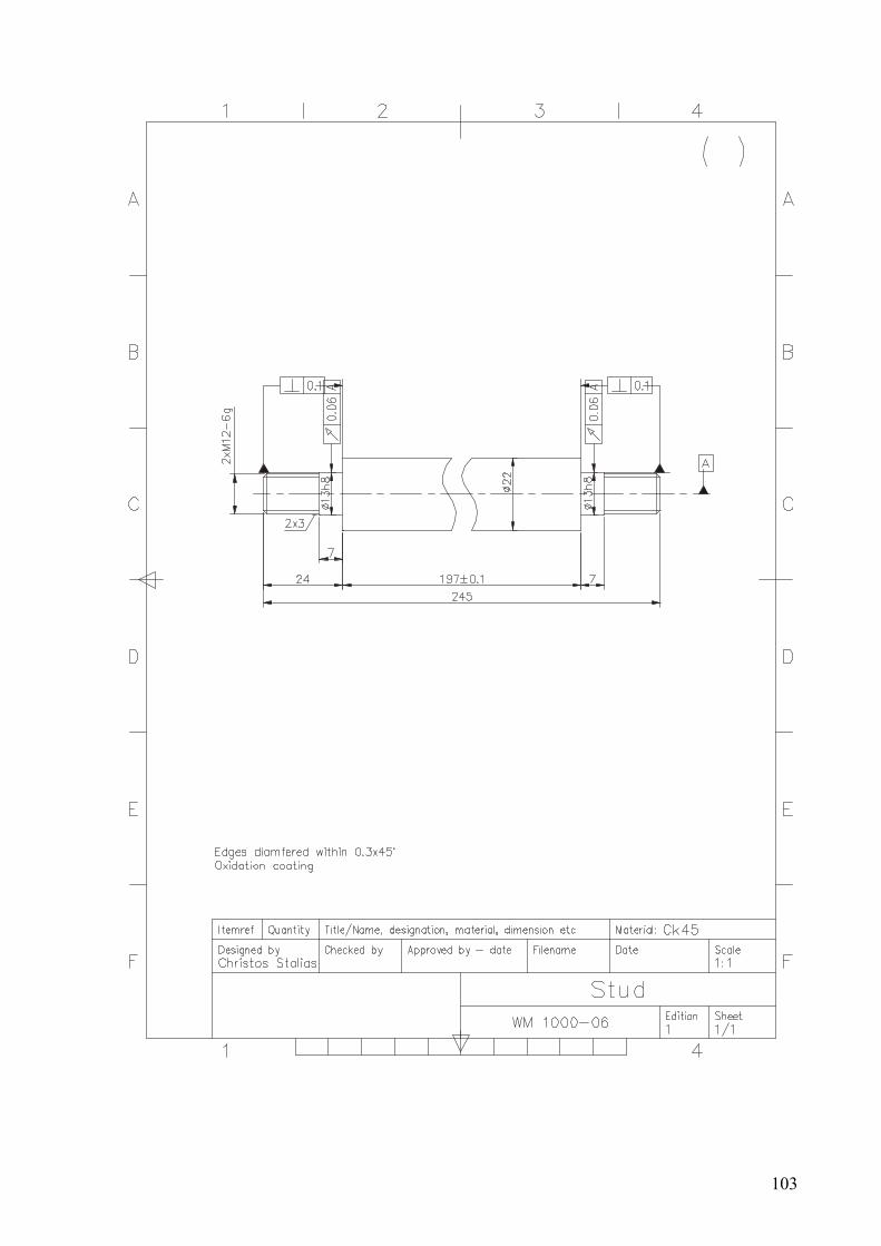
103

104

105
References
1. M. R. Mitchell, J. -G. Dessureault, A constant tension winch: Design and test of a simple passive system. Ocean Engineering, Volume 19, Issue 5, September 1992, Pages 489-496.
2. Russell K. Paul, An inexpensive instrumentation winch. Deep Sea Research and Oceanographic Abstracts, Volume 15, Issue 5, October 1968, Pages 643-644.
3. Winches, Mechanical Design for the Stage, 2007, Pages 341-358 Alan Hendrickson, Colin Buckhurst.
4. V. L. Veitz, A. I. Fedotov, L. G. Shrago, Problems concerning the dynamics of winch systems with a hydraulic brake. Mechanism and Machine Theory, Volume 10, Issue 4, August 1975, Pages 291-303.
5. L. Leland Locke, Inspector Winch's experiments on transfer. Journal of Educational Psychology, Volume 2, Issue 2, January 1911, Pages 94-95.
6. G White, Epicyclic gears from early hoists and winches —I. Mechanism and Machine Theory, Volume 29, Issue 2, February 1994, Pages 293-307.
7. G White, Epicyclic gears from early hoists and winches—II. Mechanism and Machine Theory, Volume 29, Issue 2, February 1994, Pages 309-325.
8. Stan A Burgess, Peter J Knight, Is the dynein motor a winch? Current Opinion in Structural Biology, Volume 14, Issue 2, April 2004, Pages 138-146.
9. Robert E. Wall, Maurice Ewing, Tension recorder for deep-sea winches. Deep Sea Research and Oceanographic Abstracts, Volume 14, Issue 3, June 1967, Pages 321-324.
10. C.P. Crossley, J. Kilgour, The development and testing of a winch-based small tractor for developing countries. Journal of Agricultural Engineering Research, Volume 28, Issue 2, March 1983, Pages 149-161.
11. Walter C. Beckman, R/V Vema deep-sea winch. Deep Sea Research (1953), Volume 7, Issue 1, August 1960, Pages 48, IN3, 49-52.

106
CHAPTER 7 A Bench Drilling Machine
7.1 Introduction The growing usage of this type of drills has increased significantly over the past few years and naturally, this increased the market demand of this particular size of drills. The reasons for this are: the wide range of application of bench drills in industrial production – in basic production areas and especially in repair and maintenance activities, the growing use in non-production areas, in small business activities and last but not least, at home in the house tool shop. Other reasons include affordable cost, relatively easy operation and maintenance, small external dimensions providing convenient mounting and occupying small operational space [1]. Major manufacturers of drill presses offer various models of this particular size but the fact that they are still a part of a series production line of drills is restricting design engineers to keep it to the established company image. This usually results in a rather professional final design, excessive functional and assembly detail and increase product cost, respectively.
Drilling small diameter holes in various semi-finished products and materials is constantly required in large and small-scale industrial production, maintenance and repair activities, in subcontractor workshops, at home, and in garages. The size range of these holes makes the use of large size drill presses inefficient. This means that in order to satisfy this need the machine we are going to develop should feature a specified maximum diameter of the holes drilled. This size should be sufficient to cover most frequently encountered hole diameters in production and repair industries, various services, and domestic needs [1].
This formulates the basic problem to be solved: developing a bench drilling machine intended to fill the available market niche providing simple construction, functionality, aesthetic appearance and optimum cost/quality ratio [2].
7.2 Available Product Types In order to clarify the parameters of the product to be developed we shall need to make a comparative analysis of existing similar types of machines. With this in view we selected several product types manufactured by commonly known and traditional companies in the metal-cutting equipment market. We have classified the results of this technical data analysis and the prices in the comparative Table 1. Table 1. Technical data and price comparative table Company KNUTH KNUTH TRAPANI BGU SERRMAC MAXION
Model KB 13 KB 16 16 B TB 16 RAG 16 BT 13
Technical data
Drilling capacity on steel mm 13 15 16 16 16 13 Drilling capacity on cast-iron mm 15 17 18 17 18 15
Transmission Belt drive
Belt drive
Belt drive
Belt drive
Belt drive Belt drive

107
Morse taper of spindle B16 MT2 MT2 MT2 MT2 MT2 Column diameter mm 50 80 85 80 98 65 Spindle stroke (drilling dept) mm 60 80 100 110 90 70 Table working surface mm 165x165 255x255 260x260 250x250 230x170 Clearance between spindle and column mm 190 190 201 180
Max. clearance between table and spindle mm 335 350 465
Max. clearance between base and spindle mm 500 665 415
Feed manual manual manual manual manual manual Driving motor (capacity) kW 0,18 0,37 0,7 1,1 0,55 0,45 Number of spindle speed 5 12 5 5 5 5
Spindle speed rpm 600-2500
200-3250
560-3550
250-1966 450-3000 480-4000
Dimensions (LxWxH) mm (H) 1016 680x970x360 (H) 1000 770x1120
x460 (H) 855
Weight kg 21 66 110 96 90 65 Price $670 $1050 $900 $890 $1150 $930
Тhe common feature in all machines being considered is that they all have belt drives that transmit the rotary motion from the motor to the spindle thus providing the main operating motion. Considering the type and dimension of the machine and the power required to drill 15 ÷ 16mm holes the belt drive seems to be the simplest and simultaneously the most efficient and sufficiently powerful type of drive [2]. Therefore, it is the most commonly incorporated type of drive in bench drilling equipment.
All machines are fed manually. This is performed by rotating by hand 1, 2 or 3 handles of a hub mounted on a shaft with a gear and the gear is engaged with a gear rack cut into the tailstock barrel. Thus, the rotary motion is transformed into a linear movement and the spindle is advanced (Figure 1). The maximum steel drilling diameter for most types of machines is 16mm. The front end of the spindle has a Morse taper 2. All machines being considered here have an intermediate-working table, which moves vertically up and down the column. This is achieved by manual rotation of a handle positioned on the left of the column (operator’s right) providing movable connection between the table and the column. The table and the support base usually have 2 T-slots each used to secure rigs or the component being drilled. Column diameter varies depending on the size of the machines between 50 mm and 98 mm.
From the technical parameter analysis of the product types being considered we can draw up the conclusion about the preferred parameters of the bench-drilling machine being designed.
Fig. 1

108
Table 2. Initial technical parameter table
Drilling capacity on steel 15 mm
Drilling capacity on cast-iron 17 mm
Morse taper of spindle MT2
Transmission Belt drive
Column diameter 65 mm
Spindle stroke (drilling depth) 80 mm
Table working surface 230x180 mm
Clearance between spindle and column 190 mm
Max. clearance between table and spindle 415 mm
Feed manual
Driving motor (capacity) 0,45 kW
Number of spindle speed 5
Spindle speed 240÷4000 rpm
Dimensions (LxWxH) 659x340x839 mm
Above parameters will serve as a starting point in the design process. This is the place to mention that the decision for their particular selection was made considering the overall evaluation of the technical, market and economical, technological and production factors.
From the analysis of the ergonomic characteristics we can draw the following conclusions about the ways to provide agreement between the design characteristics and the anatomic, physiological and psychological man peculiarities. A subject of the ergonomic study and design were: the height of the machines, its conformity to the size of the human body (consideration for the anthropo-metric and physiological requirements of the ergonomic characteristics), the size and slope of the spindle feed handles, which should allow convenient grip and their location on machine’s left-hand side [3].

109
Also, the direction of rotation of the handles should be:
• towards the operator (counter-clockwise) when the spindle moves downwards;
• from the operator outwards (clockwise) when the spindle moves upwards.
The upward movement is also provided by a return coil spring, which retracts the spindle in the upmost position. For the operator it is sufficient to only cyclically control the amount and speed of the upward movement.
KB13 KB16 16 B
Fig. 2 Fig. 3 Fig. 4 TB16 RAG16 BT 13
Fig. 5 Fig. 6 Fig. 7
down up Fig. 8
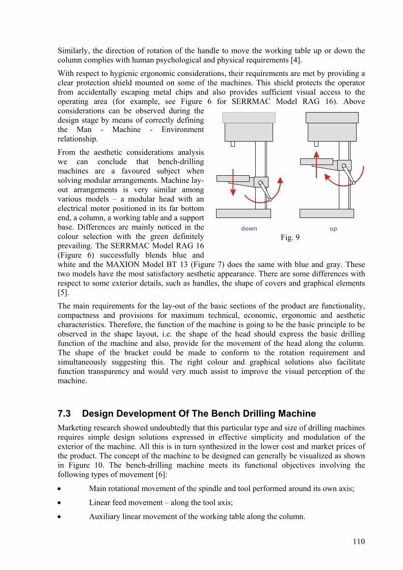
110
Similarly, the direction of rotation of the handle to move the working table up or down the column complies with human psychological and physical requirements [4].
With respect to hygienic ergonomic considerations, their requirements are met by providing a clear protection shield mounted on some of the machines. This shield protects the operator from accidentally escaping metal chips and also provides sufficient visual access to the operating area (for example, see Figure 6 for SERRMAC Model RAG 16). Above considerations can be observed during the design stage by means of correctly defining the Man - Machine - Environment relationship.
From the aesthetic considerations analysis we can conclude that bench-drilling machines are a favoured subject when solving modular arrangements. Machine lay-out arrangements is very similar among various models – a modular head with an electrical motor positioned in its far bottom end, a column, a working table and a support base. Differences are mainly noticed in the colour selection with the green definitely prevailing. The SERRMAC Model RAG 16 (Figure 6) successfully blends blue and white and the MAXION Model BT 13 (Figure 7) does the same with blue and gray. These two models have the most satisfactory aesthetic appearance. There are some differences with respect to some exterior details, such as handles, the shape of covers and graphical elements [5].
The main requirements for the lay-out of the basic sections of the product are functionality, compactness and provisions for maximum technical, economic, ergonomic and aesthetic characteristics. Therefore, the function of the machine is going to be the basic principle to be observed in the shape layout, i.e. the shape of the head should express the basic drilling function of the machine and also, provide for the movement of the head along the column. The shape of the bracket could be made to conform to the rotation requirement and simultaneously suggesting this. The right colour and graphical solutions also facilitate function transparency and would very much assist to improve the visual perception of the machine.
7.3 Design Development Of The Bench Drilling Machine Marketing research showed undoubtedly that this particular type and size of drilling machines requires simple design solutions expressed in effective simplicity and modulation of the exterior of the machine. All this is in turn synthesized in the lower cost and market prices of the product. The concept of the machine to be designed can generally be visualized as shown in Figure 10. The bench-drilling machine meets its functional objectives involving the following types of movement [6]:
• Main rotational movement of the spindle and tool performed around its own axis;
• Linear feed movement – along the tool axis;
• Auxiliary linear movement of the working table along the column.
down upFig. 9

111
The basic structural assemblies will be: (Figure 10):
1. Drilling head incorporating the following equipment mounted in it [7]:
2. Electrical motor
3. Belt drive transmission
4. Spindle assembly
5. Feed drive
6. Control panel and electrical devices
7. Cover
8. Column with a gear rack
9. Working table incorporating a mechanism for moving the table along the column
10. Machine support base
7.4 Determining the Rotation Speed & Power of The Electrical Motor
In order to calculate this we shall need to determine the cutting momentum of the drilling operation, the axial cutting force and the cutting power.
The calculations shall be based on drilling St60 using φ15 drill. We determined the cutting momentum of drilling using the following equation [7]: M = CM . dzM . syM . KM ,
where CM, zM, yM and KM are the coefficients that are indicated in the respective table.
CM =0,035
zM = 2
yM = 0,8
KM = (σB / 75)0,75 = (55/75) 0,75 = 0,79
σB = 5500.105 N/m2 is the tensile strength of this steel brand, but this is present in the equation replaced with .10-7, i.e. as 55.
M is the torque in daN;
d = 15 mm
s = 0,2 mm/rpm
M = 0,035 . 152 . 0,20,8 . 0,79 = 1,7 daNm
We determined the axial cutting force for the drilling operation using the following equation [8]:
F = CF . dzF . syF . KM ,
1
2
34 7
56
9
10
8
Fig. 10

112
where CF, zF and yF are the coefficients indicated in the respective table.
CF = 68
zF = 1,0
yF = 0,7
F = 68 . 151 . 0,20,7 . 0,79 = 261 daN
We determined the cutting power for the drilling operation using the following formula [9]:
P = 5,955
.nM , where:
M = 1,7 daNm
n = 230 rpm is spindle speed of rotation
P = 5,955
230.7,1 = 0,41 kW
The power that is required for the electrical motor PM is going to be [9]:
PM = 1
2.ηηB
P , where:
ηВ .= 0,99 is the efficiency coefficient of a ball roller bearing;
η1 .= 0,95 is the belt drive efficiency.
PM = 95,0.99,0
41,02 = 0,44 kW.
Therefore, I select IS.KL”B” BAUGRR80 electrical motor of 0.55 kW power and 1450 rpm.
7.5 Kinematical Calculations for the Belt Drive As we already clarified when we described the design solution concept the machine shall be driven by means of a 5-stage belt gear drive, which should provide for spindle speed range within 230 ÷4000 rpm.
Each of the two belt pulleys, the driving one (the one on the motor) and the driven one (the one on the spindle) shall be designed to provide 5 speed stages (having 5 shoulders). Speed change shall be by moving the belt to the desired shoulder. Multi-V-shaped belt shall be used for the belt gearing.
In this situation the preliminary calculation of all five speed stages is as follows [10]:
Gear ratio of the first belt gearing (the lowest one):

113
16,014502301,1
1 ===mn
ni
where n1,1 is the speed of rotation of the first stage of the driven pulley.
To provide a smooth speed stage change the index is going to be: ϕ = 2.05.
i2 = ϕ.i1 = 2,05.0,16 = 0,33
i3 = ϕ2.i1 = ϕ.i2 =2,05.0,33 = 0,68
i4 = ϕ3.i1 = ϕ.i3 = 2,05.0,68 = 1,4
i5 = ϕ4.i1 = ϕ.i4 = 2,05.1,4 = 2,9 We assumed for the design the following diameters of the driven belt pulleys (d1,i ) and calculate the respective diameters of the driving belt pulleys (d2,i ), the gear ratios (ii ) and the speed of rotation for every stage (ni ). The results are shown in Table 3 underneath:
Table 3
d 1,i d 2,i i i ni
60.7 178.72 i 1 =2.94 4180
100.5 143.69 i 2 =1.42 2030
144.12 100.5 i 3 =0.69 990
178.71 60.5 i 4 =0.34 480
200.94 32.5 i 5 =0.16 230
The speed stage layout for the drilling machine is as shown in Figure 11.
The length of the belt is calculated based on the centre distance A:
( ) ( )AddddAL i .42
.22
122
−+++=
π
We assumed the centre distance is A = 360 mm. Then from [10]:
( ) ( )360.4
7,6072,17872,1787,60214,3360.2
2−+++=L = 1105,56 mm
ni 41802030990480230
1450rpmn =M
Fig. 11

114
The value thus obtained for L is rounded to the nearest standard (catalogue) value for belt lengths. Based on the standard value from the catalogue Lc = 1140 mm I re-calculate the centre distance A:
( ) ( )[ ] ( ){ }212
222 .8..2.2.
81 ddddLddLA iic −−+−++−= ππ
A = { ( )++− 72,1787,60.14,31140.2.81
( )[ ] ( )22 7,6072,178.872,1787,60.14,31140.2 −−+−+ }
A = 377 mm
The circumferental belt speed v is [11]:
27,1360
4180.7,60.14,360
.. 11 ===ndv π m/s
Belt durability check based on the number of runs per second [12]:
The allowable number of runs per second umax ≤ [15] u = v / L = 13,27 / 1,140 = 11,64 < [15] runs per second.
The angle of range of the small pulley is:
≈−
°−°=−
°−°=377
7,6072,178.60180.60180 121 A
ddα 161° > 120°
For V-belt gear drives it is allowed to have a minimum angle of range of αmin = 120°. As we are going to use multi-V-shaped belt we can calculate the number of V-shapes z using the equation [12]:
pFPzσ.
= , where
P = 1000.0,55/13,27 = 41,44 N is the peripheral force;
F = 27.10-6 m2 is the belt cross section
σp is the allowed efficient stress in MN/m2, which is determined using the formula:
σp = (σp )0 . c1 . c2 . c3 = 0,456075 MN/m2 .0,96.0,957. 0,99
σp = 0,414815 MN/m2
(σp )0 = 0,456075 MN/m2 –is the induces efficient stress in the belt;
c1 = 0,96 –is the coefficient of the angle of range α1 =161° c2 = 0,957 –is the speed coefficient calculated by interpolation for the speed v = 13,27 m/s
c3 = 0,99 – is the operation condition coefficient.
For the number of V-shapes we received:
z = 414815.10.2744,41
6− = 3,7

115
We assumed z = 4, and selected the Ribbed vee-belt V; 4 PJ 1140 belt type:
The motor layout shall be as the usual one for this class of machines – secured in the back bottom end of the head cover.
When provision is made to vary the centre distance belt pre-tensioning could be provided by shifting the shaft over which the driving belt pulley is mounted (the electrical motor shaft).
Belt tightening and loosening is done by means of the tightening handle (3) and the special grooves (5) provided in the plate (1), where the motor (4) is secured by means of the bolts (2) (see Figure 12). The exact sequence of operations for changing the speed of rotation and belt tensioning is provided underneath in the machine operation procedure paragraph.
7.6 Bearings Calculations We determined the support reactions at the bearing of the spindle. Initially, we determined the circumferential force acting on the belt pulley P1:
P1 = 2.M/D = 2.17 / 0,2 = 170 N ,where:
D = 0,2 m is the belt pulley diameter;
M = 17 Nm is the torque.
The resultant force loading the motor is [11]:
Q = 3.P1 = 3.170 = 510 N
We determined the support reactions in the supports A and B. Figure 13 shows the spindle load diagram.
Rb - Ra = Q ⇒ Rb = Ra + Q
ΣMB = 0 = Ra.0,163 – Q.0,025 Ra = 510.0,025/0,163 = 78 N
Rb = Ra + Q = 78 + 510 = 588 N
The bearing subjected to higher load is the one in the support B. We calculate the serviceability factor for the bearing, which is subjected to the load of the radial force Rb = 58.8 daN and axial cutting force F = 261 daN.
C = (n.h)0,3.(Rb.Kk + m.F).Kb.Kt , where:
n = 230rpm;
12
3
4
5
Fig. 12
F
Ra
Rb
Q
0,027m
0,163m
0,025m
B
A
Fig. 13

116
Kk = 1,0 is a coefficient indicating which one of the bearing rings is currently rotating
m = 1,5 is a coefficient indicating the uneven effect of the radial and axial load on the bearing durability;
Kb = 1,2 is a factor indicating the effect of the load;
Kt = 1,0 is a coefficient indicating the effect of operation temperature of the motor;
h = 5000h is the bearing durability.
We selected the SKF 6005RS type bearing with the following dimensions: 25x47x12mm and Co = 65.5 kN [13].
7.7 Calculating the Feed Gear Drive We have already mentioned that the machine is fed manually by rotating the levers (7) with the handles (8), which actuate the shaft (6) where they are mounted (Figure 14). The shaft itself is shaped as a shaft-gear with the gear (15) cut out in it. This geared shaft is engaged with the gear rack cut into the quill. The rotary motion of the geared shaft is thus transformed into linear movement of the quill and spindle.
The maximum quill travel is l = 80 mm. Now I have to determine the index and number of gear teeth and the size of the gear and gear rack.
We assumed the gear drive index m = 2 mm. From ergonomic considerations [12] it is desirable that the maximum travel of the quill and spindle is achieved with approximately 0.75 turns of the feed handles, i.e. the gear should rotate 0.75 rounds.
75,0.
≈dl
π ,
where:
d = m.z is the gear pitch diameter;
m = 2 mm is the index;
z is the number of gear teeth;
l = 80 mm is the maximum quill travel.
14,3.75,080
.75,0==
πld = 33,97 mm
d = m.z ⇒ z = d/m = 33,97/2 = 16,985 teeth. To avoid the chance of undercutting the teeth for no displacement gears cut using a standard rack-type tool, we assume the maximum number of teeth zmin ≥ 17 . We assumed the number of gear teeth z = 18. We obtained the following values for the gear geometrical dimensions:
d = m.z = 2.18 = 36 mm – pitch diameter
De = m.(z + 2) = 2.(18 + 2) = 40 mm – outside diameter
Di = m.(z – 2,5) = 2.(18 – 2,5) = 31 mm – inside diameter.
Gear tooth height is h = 4.5.

117
For the gear rack I get:
Pitch – t = m.π = 2.3,14 = 6,28 mm Minimum number of teeth on the rack – 13.t = 13.6,28 = 81,64 mm.
We assumed 15 teeth + another 12 mm technology cut for the removal of the drill, which would guarantee quill travel of 80 mm.
We do not need to make calculations for the teeth contact strength because the machine is a hand-driven type. Provision is made for adjusting the drilling depth (Figure 14) by means of the tightening handle (1), the pin (2) and the scale (3) [14].
The screw (4) secures the feed shaft axially entering a special groove. Mounted at the end of the shaft and in a special recess in the casing is the flat coil retraction spring (9), which serves to retract the quill upwards. The recess is covered by the cap (10).
7.8 Design Conceptualisation of THE Work Table Moving Mechanism
The vertical movement of the worktable along the column is accomplished by rotating the handle 1 (Figure 15), positioned on the worm (2) axle. The worm (2) is in turn engaged with the gear rack (4) positioned vertically along the column (5). The engagement is located in the work table (6) arm.
Worm parameters:
Worm axial index m = 2 mm.
Number of worm strokes z1 = 1.
Worm pitch diameter De = 20 mm
Worm external diameter De = 20 mm
Worm internal diameter Di = 16 mm
Angle of ascent of the helical line 7°. Gear parameters:
Index m = 2mm
Number of gear teeth z2 = 12
Pitch diameter d = m.z = 2.12 = 24 mm
External diameter De = m.(z + 2) = 2.(12 + 2) = 28 mm
Fig. 14
3
5
6
1
2
4
Fig. 15

118
Internal diameter Di = m.(z – 2,5) = 2.(12 – 2,5) = 19 mm
Angle of slope of gear teeth – righthand 7°. The gear rack is not statically fixed to the column. It rotates around the column along its diameter and is restricted from the casing above and the base underneath. The worktable will thus be capable of rotating around the column. The worktable arm is provided with a cut in the back section to allow for the movement or rotation of the worktable and a special handle allows tightening or loosening it around the column.
7.9 Support Base of the Bench-Drilling Machine (Figure 16) The column is attached to the support base by means of four bolts. Two T-grooves (12 mm) are provided in the base, which can be used to secure parts having large size. The worktable will have to be lowered (or rotated in the backward direction) in this case.
The machine should be mounted on a stable support or bench. It should be secured in position by means of M10 bolts through the three opening provided in the support base of the machine.
7.10 Ergonomic & Aesthetic Appearance Machine Conceptualisation
Some ergonomic considerations should be observed when selecting a suitable location for the handle levers providing the feed to the machine. These are located on the left-hand side of the machine’s head (operator right-hand side). Two levers are provided at 180°. This is acceptable for this type and size of drilling machine [15]. This is determined by the short quill travel, which is achieved by less than a single full turn (around 0.71 turns of the levers). Also, the two levers and handles alternative is preferable from economical viewpoint. The levers themselves are slanted at 30° outwards from the casing, which allows for their rounded tips, the handles, to be positioned at a distance from the machine cover thus providing more than 30 mm free space. It makes it convenient for the operator to hold them with his fingers and move them easily. A larger slope than this one would be rather inconvenient for the operator to turn them.
The downward feed of the quill is an operational movement, which is performed by hand by the operator. We have already mentioned that this should be accomplished by turning the handles towards “themselves” because this direction is considered to comply with the physical and psychological characteristics of the operator. Moreover, ergonomic studies show that the “towards oneself” direction of movement is performed easier than, for example “outwards from oneself” and “to the side” direction and therefore this is usually recommended for operational movements. Handles are bought out components that are specifically designed for convenient grip by the human hand.
270
258
390
300
21
21 3x 10,5∅
Fig. 16

119
The worktable-moving handle has also been examined from ergonomic viewpoint before the final design solution was adopted. Movement transmission via a worm, a gear and a gear rack provides for considerable reduction of the human muscular effort required. Moreover, the directions of rotating the handle, which moves the table up or down are made identical to those for the quill feed. In other words, when the handle is turned in the “towards you” direction moves the table downwards and turning it “outwards from yourself” moves the table up.
A protective transparent cover is provided to ensure safe machine operation. This serves to protect the operator from accidentally flying metal chips. The cover is installed on the right-hand side of the casing and has adjustable length. It is a bought-out part and is chosen to have a shape that complies with the shape of the head of the machine. In particular, this is expressed by the correspondence between the vertical ribs provided in the protective cover and the vertical grooves in the head.
A switch is installed on the head cover, which automatically turns the motor off when the cover is opened. Thus, additional safety is added when belt replacement is required. The cover itself is made of plastic material and is opened sideward with a minimum effort required from the operator. The colour of the cover is different to that of the machine head thus underlining its enclosing function. The dark colour of the cover matches the dark colour of the face-mounted nameplate thus achieving colour matching of the front view of the head – smooth colour flow in the direction of operational feed of the quill and spindle. Moreover, the shape of the cover provides natural and logical continuity and finalization of the shape of the head of the machine.
When developing the aesthetic appearance of the bench-drilling machine the objective was to achieve functionality, compactness and possibilities to provide maximum technical, economical, ergonomic and aesthetic characteristics through the arrangement layout of the basic sections of the product. Therefore, a basic shape-formation principle in my compositional solution was the function of the product; i.e. the shape of the head of the machine expresses the basic drilling function. Precise colour and graphical solutions also assist to improve the visual perception of the machine.
7.11 Operation of the Machine The machine is provided with a control panel located in the front of the casing. The following elements are installed in it:
1. Three-position switch:
- left spindle rotation;
- motor switched off
- right spindle rotation.
2. Main circuit breaker with two positions:
- power on
- emergency stop
3. Power on indicator light.
Putting the machine into operation is by means of positioning the main circuit breaker in the “I” position to turn power on. The three-position
0
0I

120
switch is used to turn the motor on and hence, the rotation of the spindle in the desired direction. The rotating tool is advanced towards the part to be drilled by means of the feed handles. Rotation is switched off by means of positioning the three-position switch in the “0” position. Power is switched off by turning the main circuit breaker to “0” position.
Changing the speed of rotation is accomplished in the following sequence:
- Switch the machine off;
- Open the cover;
- Loosen the handle (3), Figure 12;
- The motor is pushed slightly towards the spindle to loosen the belt;
- The belt is adjusted to the desired gearing and then tightened by pushing the motor back in position;
- Tighten the handle (3);
- Close the cover.
Regular lubrication of some of the assemblies is necessary to be provided during machine operation. These are shown in Figure 17 along with the proper types of lubricants and recommended frequency of application.
7.12 Conclusions The bench-drilling machine is designed for drilling blind and through holes and for additional machining of holes made in forged, die-cast, etc. semi-finished products. The product satisfies the market demand for small-size (bench) drilling machines. The maximum diameter of holes drilled in steel parts is φ15 mm, complying to a maximum extend to its functional intended purpose, i.e. performs all basic functions it has been designed for. The type of construction provides easy installation, convenient operation and maintenance. The manufacturing producability of assemblies and component parts has been one of the main objectives perceived throughout the overall design process. Special study and development was devoted to the ergonomic considerations for the machine and the aim pursued here was to provide optimum matching of the product with the human factor peculiarities. Thus, convenient and simple machine operation was achieved as well as possibilities for continuous operation without exhausting the operator or threatening his health. The aesthetic appearance of the bench-drilling machine is guaranteed by the in-depth clarification of the compositional and functional relationship between major machine sections, as well as by the compactness and neat and simple shape attained [16]. This contributes to the appearance and complies with the tendency for increased market demand for products that have been designed to satisfy the artistic sense of customers.
Fig. 17

121
Satisfying the marketing criteria and the peculiarities of the market demand, and in combination with the lower selling price compared to that of competitive products of the same class, the winch can quickly take the established market niche and gain lasting and financially backed-up success.
Bench Drilling Machine – Specification Tables
Specification BD 1502-00
Item Designation Description Qty. Material Remarks
1. BD1502-10-Z02 Base complete 1
2. BD1502-11-Z02 Inter. Table complete 1
3. BD1502-12-Z01 Drill head complete 1
4. BD1502-20-M01 Drill spindle complete 1
5. BD1502-21-Z02 Main drive complete 1
6. BD1502-51-Z01 Feed drive complete 1
Bench Drilling Machine BD15

122
7. BD1511-70-017 Warning nameplate 1 D, E, F
8. BD1502-82-Z01 Cover complete 1
9. 0027045 Electrical motor 1450 0.55kW V3 FL200 230/400V 50Hz
1 IS.KL “B” BAUGR80 1.3 – 1.6 A
10. 068293 Front panel complete 1
11. 0682989 Electrical materials 1
BD 1502-10-Z02 Support Base
Item Designation Description Qty. Material Remarks
1. BD1502-10-004 Support base 1 GG20
2. BD1602-10-002 Column 1 C45
3. 448 Screw M 8x30-DIN 912-8.8
4 Bought out
4. 320598 Plug 3 Bought out
BD1502-11-Z02 Intermediate Table
Item Designation Description Qty. Material Remarks
1. BD1502-10-003 Intermediate table 1 GG20
2. BD1502-11-001A Gear rack 1 C45
3. BD1502-11-002 Worm 1 C45
4. BD1602-11-003 Rack gear 1 C45
5. BD1602-11-004 Axle 1 C45
6. GN 300-78-M8-50-SW FA.GANTER
Tightening lever 1 Bough out
7. 1602-11-005 GN 471.1-80.B12 FA.GANTER
Handle 1 Bought-out
8. 60806 ULMER M5x8 Threaded pin 1 DIN 913-45H bought-out
9. 68718 ULMER Washer 13 (or 12x18x1 washer)
DIN 433 or DIN 988 Bought-out
10 692194 Special Bushing 1 Bought-out

123
BD1502-12-Z01 Drilling Head
Item Designation Description Qty. Material Remarks
1. BD1502-12-001 Drilling head 1 GG 20
2. BD1511-12-002 Cap, black 1 Bought-out
3.
M8 x 30 Screw DIN-912-8.8
4 Bought-out
BD1502-20-M02 Drilling spindle MK2, short
Item Designation Description Qty. Material Remarks
1. BD1602-20-003 Quill 1 GG 20
2. BD1602-20-004 Drill spindle MK2, short 1 Ck67
3. Radial ball bearing 6005 RS
2 FAG, SKF
4. Clip ring B 25 x 1.2 1 DIN 471
5. R 6.6 Washer 1 DIN 440 Bought-out
6. M 6 x 12 Bolt 1 DIN 933-8.8
7. PS 25x35x1.0 Compensation washer
1 DIN 988 Bought-out
8. PS 25x35x0.2 Compensation washer
3 DIN 988 Bought-out
9. PS 25x35x0.1 Compensation washer
2 DIN 988 Bought-out
BD1502-21-M01 Slot bushing
Item Designation Description Qty. Material Remarks
1. BD1602-21-004 Slot bushing 1 C45
2. BD1502-21-005 Key 1 Additionally ma chined from 6x6x22
3. BD1602-21-007 Spacer bushing 1 C45
4. M 4x8 Screw 1 Din 912 Bought-out
5. Clip ring B 30 x 1.5
1 DIN 471 Bought-out
6. Radial ball bearing 16006
2 FAG, SKF Bought-out

124
BD1502-21-Z02 Main Drive
Item Designation Description Qty. Material Remarks
1. BD1502-21-M01 Slot bushing complete 1
2. BD1602-21-002A Belt pulley 1 GG 25
3. BD1602-21-003A Belt pulley 1 GG 25
4. BD1602-21-006 Flange 1 C45
5. BD1502-82-001 Cover plate 1 St37M Sub-supplied
6. BD1502-21-008 RPM nameplate 1
7. Countersunk screw M 6x16
1 DIN 7991 Bought-out
8. M 6x12 Screw 4 DIN 912 Bought-out
9. M 6x20 Screw Bulgarian National Standard 2171-83
1 DIN 912 Bough-out
10. M 6x25 Screw 2 DIN 912 Bought-out
11. 454678 Ganter
GN 184-32 Washer 1 Bought-out
12. 692244 Conti-v-multirib belt 1 DIN 7867 4 PJ 1140 bought-out
13. O-ring 49.5 x 3 1 Bought-out
14. 422 M 6 Nut 1 Oxidized Bought-out
15. 5454 M 10 Nut 3 Oxidized Bought-out
16. 8540 M 10x35 Bolt 3 DIN 933 Bought-out
17. 3467 Washer B 10.5 1 DIN 125 Bought-out
18. Threaded pin M 6x16 1 Din 915 Bought-out
19. 353540 FA.GANTER
Tightening lever GN 300-63-M10-25-SW
1 Bought-out
20. Hinge 2 Bought-out

125
BD1502-51-M01 Feed drive
Item Designation Description Qty. Material Remarks
1. BD1502-51-001 Geared shaft 1 C45
2. BD1502-51-002 Lever 2 C45
3. BD1502-51-005 Vernier 1 C45
4. BD1502-51-006 Dial scale 1
5. BD1511-51-001 Handle 2 Bought-out
6. 692327 ULMER
5 dia x 14 Pin 1 DIN 1481 Bought-out
7. 352955 FA.GANTER
Tightening lever GN300-45-M6-20-SW
1 Bought-out
8. 943 ULMER
2 dia x 4 Rivet 4 DIN 1476 Bought-out
BD1502-51-Z01 Feed drive
Item Designation Description Qty. Material Remarks
1. BD1502-51-M01 Feed drive 1
2. BD1502-51-004 Cap 1 St37M
3. BD1501-51-003 Retracting spring 1 Ck67
3.1 BD1501-51-003-01 Bandage 1 St37M
3.2 Rivet 2 dia x 4 4 Bought-out
4. 82362 ULMER
Screw M.I-6KT.M6x10 ULS 10.9
2 ISO 7380 Bought-out
5. 8383 ULMER
6 x 36 Pin 1 DIN 1481 Bought-out
6. 35212 (H 4)
M 8x20 Screw 1 DIN 915 Bought-out
BD1502-70-Z01 Electrical installation
Item Designation Description Qty. Material Remarks
1. BD1502-70-001 Face plate 1
2. BD1502-70-002 Gasket 1
3. M 4x10 Screw 2 DIN 84 Bought out
4. BD1502-70-003 Angle iron 1
5. 82362 ULMER
Screw M.I-6KT M6x16 ULS
4 UN 19 Bought-out
6. 82388 ULMER
Screw M.I-6KT M6x16 ULS
4 Un 19 Bought-out

126
7. M4x25 Screw 2 DIN 912 Bought-out
8. M6 Nut 1 DIN 934
BD1502-82-Z01 Cover
Item Designation Description Qty. Material Remarks
1. BD1502-82-002 Cover 1
2. BD1502-82-003 Strip 1 St37M
3. BD1502-82-004 Strip 1 St37M
4. BD1502-82-005 Stop 1 C45
5. BD1511-70-017 Nameplate GB/D/F 1
6. 708222 Manufacturer’s nameplate 1
8. 692343 ULMER
Screw M.I-6 KT M 4x10 ULS
2 UN 19 Bought-out
9. 692368 Latch PA 0. 0. 388.20
1 Bought-out
10. M6 x 16 Screw 2 DIN 912
11. M 3 Nut 6 ISO 4032

127

128

129

130

131

132

133

134
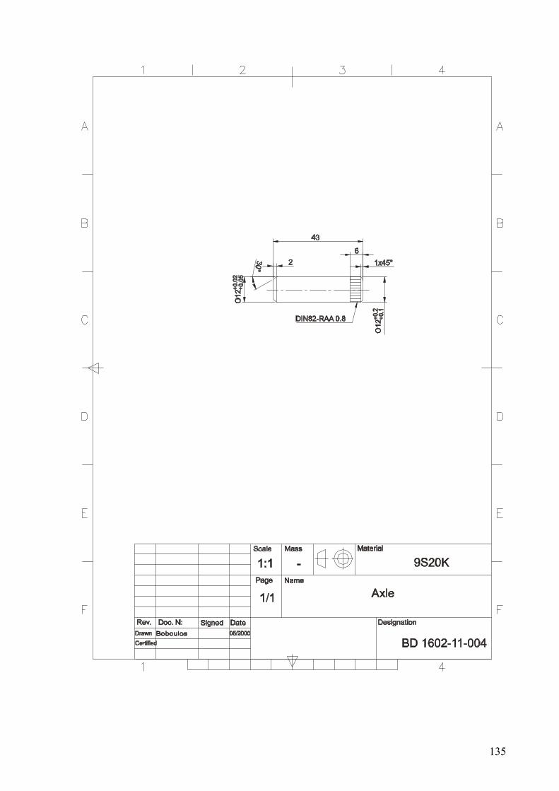
135

136
References
1. Jacek Karliński, Eugeniusz Rusiński, Tadeusz Lewandowski, New generation automated drilling machine for tunnelling and underground mining work. Automation in Construction, Volume 17, Issue 3, March 2008, Pages 224-231.
2. Godfrey C. Onwubolu, Shivendra Kumar Response surface methodology-based approach to CNC drilling operations. Journal of Materials Processing Technology, Volume 171, Issue 1, 10 January 2006, Pages 41-47.
3. R.S. Xia, S.M. Mahdavian, Experimental studies of step drills and establishment of empirical equations for the drilling process. International Journal of Machine Tools and Manufacture, Volume 45, Issue 2, February 2005, Pages 235-240.
4. J. S. Strenkowski, C. C. Hsieh, A. J. Shih, An analytical finite element technique for predicting thrust force and torque in drilling. International Journal of Machine Tools and Manufacture, Volume 44, Issues 12-13, October 2004, Pages 1413-1421.
5. L. -B. Zhang, L. -J. Wang, X. -Y. Liu, H. -W. Zhao, X. Wang, H. -Y. Luo, Mechanical model for predicting thrust and torque in vibration drilling fibre-reinforced composite materials. International Journal of Machine Tools and Manufacture, Volume 41, Issue 5, April 2001, Pages 641-657.
6. Nicolas Guibert, Henri Paris, Joël Rech, A numerical simulator to predict the dynamical behavior of the self-vibratory drilling head. International Journal of Machine Tools and Manufacture, Volume 48, Issue 6, May 2008, Pages 644-655.
7. Nicolas Guibert, Henri Paris, Joël Rech, Christophe Claudin, Identification of thrust force models for vibratory drilling. International Journal of Machine Tools and Manufacture, Volume 49, Issue 9, July 2009, Pages 730-738.
8. Begoña Peña, Gorka Aramendi, Asunción Rivero, Luis N. López de Lacalle, Monitoring of drilling for burr detection using spindle torque. International Journal of Machine Tools and Manufacture, Volume 45, Issue 14, November 2005, Pages 1614-1621.
9. Sukanta Bhowmick, Michael J. Lukitsch, Ahmet T. Alpas, Dry and minimum quantity lubrication drilling of cast magnesium alloy (AM60). International Journal of Machine Tools and Manufacture, Volume 50, Issue 5, May 2010, Pages 444-457.
10. Erkki Jantunen, A summary of methods applied to tool condition monitoring in drilling. International Journal of Machine Tools and Manufacture, Volume 42, Issue 9, July 2002, Pages 997-1010.
11. Joong-Bae Kim, Sang-Jo Lee, Young-Pil Park, Development of a drilling process with torque stabilization. Journal of Manufacturing Systems, Volume 13, Issue 6, 1994, Pages 435-441.
12. S. Kahraman, Correlation of TBM and drilling machine performances with rock brittleness. Engineering Geology, Volume 65, Issue 4, September 2002, Pages 269-283.
13. Reuven Katz, Zhe Li, Kinematic and dynamic synthesis of a parallel kinematic high speed drilling machine. International Journal of Machine Tools and Manufacture, Volume 44, Issues 12-13, October 2004, Pages 1381-1389.
14. R.S. Bais, A.K. Gupta, B.C. Nakra, T.K. Kundra, Studies in dynamic design of drilling machine using updated finite element models. Mechanism and Machine Theory, Volume 39, Issue 12, December 2004, Pages 1307-1320.

137
15. K. R. Wardak, U. Tasch, P. G. Charalambides, Optimal fixture design for drilling through deformable plate workpieces part II: results. Journal of Manufacturing Systems, Volume 20, Issue 1, 2001, Pages 33-43.
16. R. Natarajan, Analysis of a radial drilling machine structure using finite element method. Computers & Structures, Volume 6, Issue 1, February 1976, Pages 55-60.
