mechanism feasibility design task - github pages · 2017-06-20 · mechanism feasibility design...
TRANSCRIPT

Mechanism Feasibility Design Task
Dr. James Gopsill
1Design & Manufacture 2 – Mechanism Feasibility Design
Lecture 3
2017

Contents
1. Last Week
2. The Convertible Roof System
3. Boundary Calculations
4. Modelling the Deployment using Simulink• Pendulum
• Fix it in position
• Deploy the pendulum
5. Stage-Gate Reminder
6. This Week
2Design & Manufacture 2 – Mechanism Feasibility Design
Lecture 3
2017

But First!
Points of Clarification
• Soft-top roof – lecture 2
• No sliding pins (time constraints) – lecture 2
• Unable to get Linkage on theUniversity PCs this year
• Your criteria is your PDS
3
2017
Design & Manufacture 2 – Mechanism Feasibility Design
Lecture 2
YOUR PDS!!

Last Week
We looked at:• Product Design Specifications Techniques
• Concept Generation Techniques
• Concept Selection Techniques
Where we should be:• Formed Product Design Specification
• Generated Concept Designs
• Started to Select a Concept to Carry Forward
• Ready for the Stage-Gate Submission
4
Product Design Specification
Concept Design
Concept Selection
Deployment Modelling
Stage-Gate
Design & Manufacture 2 – Mechanism Feasibility Design
Lecture 3
2017

Systems Modelling
5Design & Manufacture 2 – Mechanism Feasibility Design
Lecture 3
2017

Systems Modelling
The development of models that simulate complex engineering systems that often span multiple
engineering disciplines
6Design & Manufacture 2 – Mechanism Feasibility Design
Lecture 3
2017

Systems Modelling (illustration)
7Design & Manufacture 2 – Mechanism Feasibility Design
Lecture 3
Compressor
S1 S2 Sn
Combustion Turbine
S1 S2 Sn
Control system
Engine bleeds
Air breathingOperating Conditions
Pilot
Prop Gearbox
Wing anti-icing
2017

Systems Modelling
8Design & Manufacture 2 – Mechanism Feasibility Design
Lecture 3
Not forgetting!
• Fuel system
• Cooling system
• Lubrication system
• Engine start system
Other Jet Engines
• Varying intake
• Reheat
2017

Systems Modelling (Why?)
9Design & Manufacture 2 – Mechanism Feasibility Design
Lecture 3
• Global optimisation of the
products design
• Performance analysis
• Sensitivity analysis
• Product health monitoring
• Diagnosis of product issues
• Pass-off tests
2017
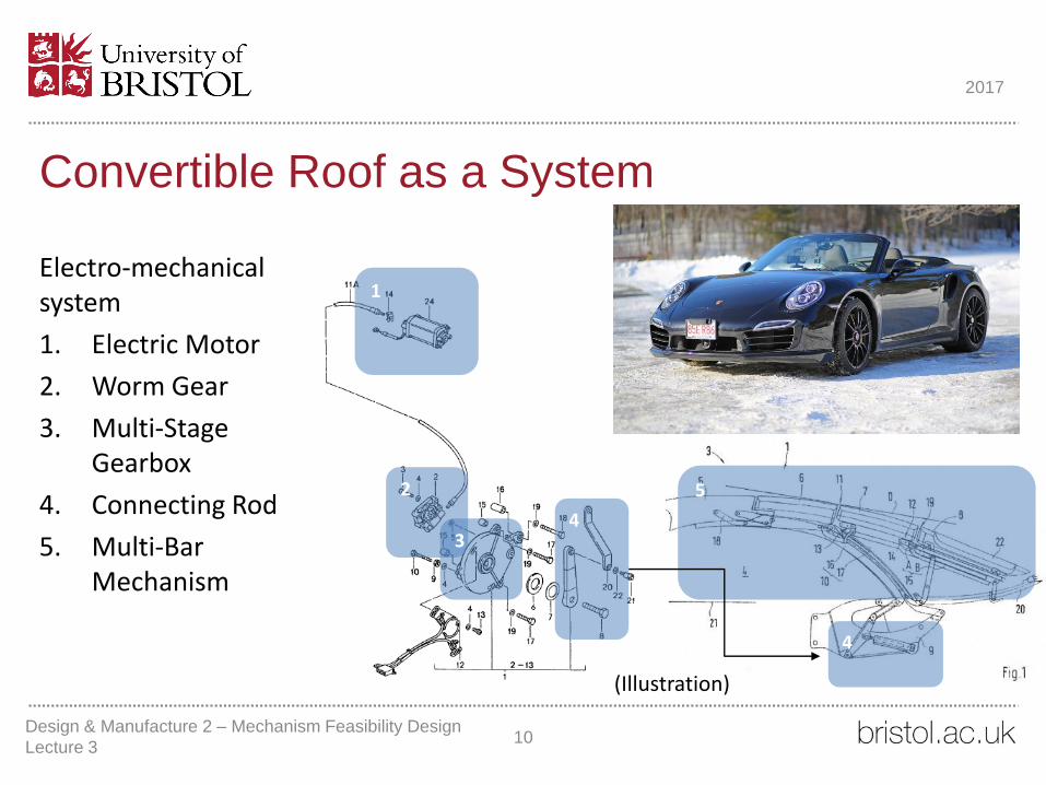
Convertible Roof as a System
10
1
2
3
Electro-mechanical system
1. Electric Motor
2. Worm Gear
3. Multi-Stage Gearbox
4. Connecting Rod
5. Multi-Bar Mechanism
4
4
5
Design & Manufacture 2 – Mechanism Feasibility Design
Lecture 3
(Illustration)
2017

Convertible Roof as a System
Energy transfer through the system• Power to the motor
provides initial torque
• Torque travels through the gear box where the gear ratio will change the amount of torque delivered
• Which then drives the mechanism against gravity (initially)
11Design & Manufacture 2 – Mechanism Feasibility Design
Lecture 3
2017

Convertible Roof as a System
12
https://www.youtube.com/watch?v=UqcKYFU6VIg
Design & Manufacture 2 – Mechanism Feasibility Design
Lecture 3
2017

Boundary Calculations
13Design & Manufacture 2 – Mechanism Feasibility Design
Lecture 3
2017

Boundary Calculations (Why?)
• Help us determine initial conditions for our models
• Provide a sanity check for our models
• Provides evidence for our initial component selection
14Design & Manufacture 2 – Mechanism Feasibility Design
Lecture 3
2017

Boundary Calculations
What are our boundary conditions and what do we need to know?
15Design & Manufacture 2 – Mechanism Feasibility Design
Lecture 3
2017

Boundary Calculations• What torque do you require to get
the mechanism moving?
• Assume a single mass
• Think centre of mass
16
𝑚𝑔𝑙
∝
Design & Manufacture 2 – Mechanism Feasibility Design
Lecture 3
2017

Boundary Calculations• What torque do you require to get
the mechanism moving?
• Assume a single mass
• Think centre of mass
• What motor and gear ratio is required to achieve this?
• Select a motor from Bosch
• Refer to your PDS when selecting the motor
• Determine the gear ratio required
• Note: you will need a gear ratio!
• Record your rationale for your choice
17
𝑚𝑔𝑙
∝
http://www.bosch-ibusiness.com/boaaelmoocs/category/D.C.%20motors%20without%20transmission/114?locale=en_GB
Design & Manufacture 2 – Mechanism Feasibility Design
Lecture 3
2017

Boundary Calculations
18Design & Manufacture 2 – Mechanism Feasibility Design
Lecture 3
Design Report
• Deployment Modelling (Boundary Calculations)• How did you calculate the torque required?
• What were your assumptions?
• From this information and your PDS, how did you determine the initial gear ratio & motor
2017
Modelling the System
19Design & Manufacture 2 – Mechanism Feasibility Design
Lecture 3
2017

Modelling the System
What do we want to know?
• Energy required to deploy the roof
• Time to deploy the roof
• To help us determine the final Motor, Gear Ratio and Damping values
20Design & Manufacture 2 – Mechanism Feasibility Design
Lecture 3
2017

Modelling the SystemWhat is changing over time?
• Torque provided by the motor
• Force due to gravity
• Inertia of the mechanism
• Mechanism• Acceleration
• Velocity
• Displacement
What remains constant?• Gear ratio
• Mass of mechanism
21Design & Manufacture 2 – Mechanism Feasibility Design
Lecture 3
2017

Modelling the System
What assumptions are we making?
• Friction
• Air Resistance
• ?
If included, what effect would they have?
This is important to know so we can be analyse the results in the appropriate context. (Put this in your report)
Design & Manufacture 2 – Mechanism Feasibility Design
Lecture 322
2017

How are we going to model this?
• Simulink
• A block modelling language that is great for modelling systems.
• Blocks represent calculations that need to be performed.
• Handles the iterations and time domain for us
• We are going to use it to help us model the dynamics of a multi-bar mechanism
23Design & Manufacture 2 – Mechanism Feasibility Design
Lecture 3
2017

Demo - Pendulum
24Design & Manufacture 2 – Mechanism Feasibility Design
Lecture 3
2017

Co-ordinate System
25Design & Manufacture 2 – Mechanism Feasibility Design
Lecture 3
2017

Fixing It Into Position
26
𝑚𝑔𝑙
∝
Calculate the torque required to oppose the motion
+𝑇𝑜𝑝𝑝𝑜𝑠𝑒
−𝑇𝑜𝑝𝑝𝑜𝑠𝑒
−𝑇𝑜𝑝𝑝𝑜𝑠𝑒𝑇𝑧 +
+𝑇𝑜𝑝𝑝𝑜𝑠𝑒
𝑥
𝑦
Design & Manufacture 2 – Mechanism Feasibility Design
Lecture 3
2017

Fixing It Into Position
27Design & Manufacture 2 – Mechanism Feasibility Design
Lecture 3
2017

Deploying the Single Mass
28
𝑚𝑔𝑙
∝
𝑥
𝑦
𝑇
StartFinish
𝛽
Design & Manufacture 2 – Mechanism Feasibility Design
Lecture 3
2017

Deploying the Single Mass using a Motor
29
This will
need to
change!
• Motor Torque is a Function of Angular Velocity
• Motor Curves from Bosch
• Use Angular Velocity as the feedback
• The gear ratio will change the speed and motor
• The motor will be running at a different speed to the mechanism
• Note: Next week we will look at damping so that we can keep the motor in its operating window!
Design & Manufacture 2 – Mechanism Feasibility Design
Lecture 3
2017

Stage-gate: Submission
• Product Design Specification (Current Progress, A4 page)
• Chosen Concept Model• Images
• Paragraph discussing main features
• Online Submission Blackboard
• 5% Pass/Fail Criteria
30
No.
Requirement Must/Wish Method of Assessment
Success Criteria Will be assessed during the feasibility stage
1
2
3
…
Design & Manufacture 2 – Mechanism Feasibility Design
Lecture 3
2017

This Week• Boundary Condition Calculation
• What torque is required to get your mechanism moving?
• Assume a single mass
• Generate the Demo Models
• Pendulum
• Fixed Pendulum
• Deployment Pendulum
• Templates on the website
• Model your single mass (from your boundary calculation!) moving from start to finish using the motor and gear ratio selected
• Next Week
• Demo: Four-Bar Mechanism with Damping
31
𝑚𝑔𝑙
∝
Design & Manufacture 2 – Mechanism Feasibility Design
Lecture 3
2017