mechanics of materials - mechfamily | hu...
TRANSCRIPT
2/4/2013
1
MECHANICS OF MATERIALSMECHANICS OF MATERIALS
CHAPTER ONEINTRODUCTIONINTRODUCTION
CONCEPT OF STRESSCONCEPT OF STRESSCONCEPT OF STRESSCONCEPT OF STRESS
Prepared by : Dr. Mahmoud Rababah 1
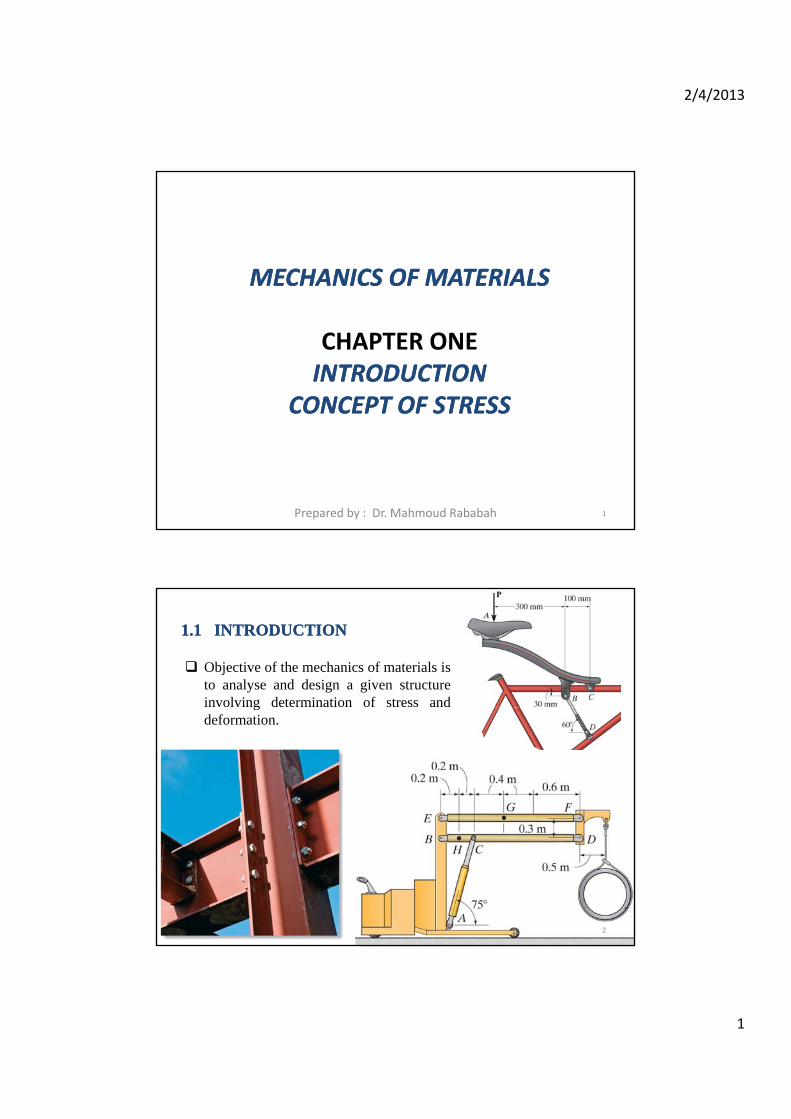
Objective of the mechanics of materials isto analyse and design a given structureinvolving determination of stress and
11..1 1 INTRODUCTIONINTRODUCTION
gdeformation.
2

2/4/2013
2
Can the system withstand the load or will break down?
The failure will start in Members? or Screws? or Bolts?
3
0
0
Then, we obtain
40 kN
x
y
F
F
F 40 kN
50 kN
AB
BC
F
F
4
2/4/2013
3
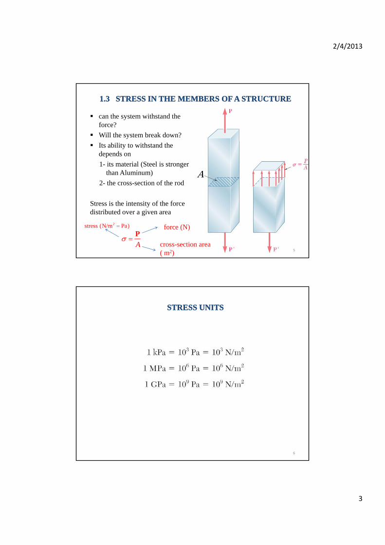
11..3 3 STRESS IN THE MEMBERS OF A STRUCTURESTRESS IN THE MEMBERS OF A STRUCTURE
can the system withstand the force?
Will the system break down?
A
Its ability to withstand the depends on
1- its material (Steel is stronger than Aluminum)
2- the cross-section of the rod
Stress is the intensity of the force distributed over a given area
A
Pforce (N)
cross-section area ( m2)
2stress (N/m Pa)
5
STRESS UNITSSTRESS UNITS
6
2/4/2013
4
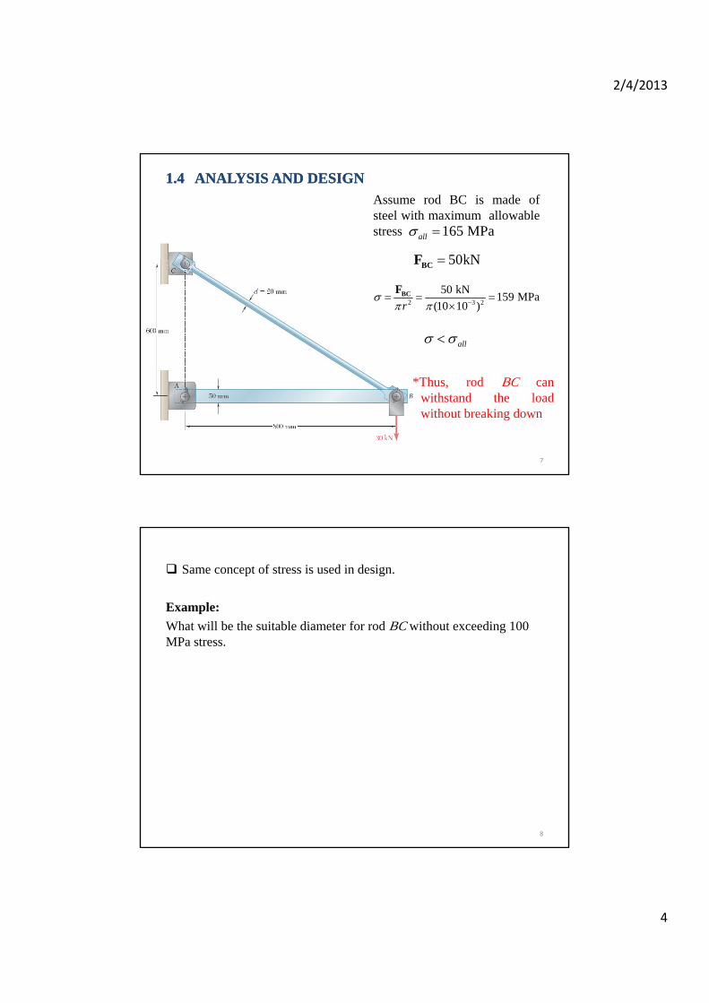
11..4 4 ANALYSIS AND DESIGNANALYSIS AND DESIGN
50kNF
Assume rod BC is made ofsteel with maximum allowablestress 165 MPaall
50kNBCF
2 3 2
50 kN159 MPa
(10 10 )r
BCF
all
*Thus, rod BC canwithstand the loadwithout breaking down
7
Same concept of stress is used in design.
Example:
What will be the suitable diameter for rod BC without exceeding 100 MPa stress.
8
2/4/2013
5
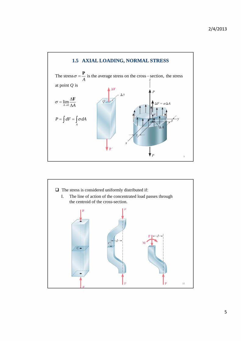
11..5 5 AXIAL LOADING, NORMAL STRESSAXIAL LOADING, NORMAL STRESS
The stress is the average stress on the cross section, the stress
at point isA
Q
P
0limA
A
A
P dF dA
F
A
9
The stress is considered uniformly distributed if:
I. The line of action of the concentrated load passes throughthe centroid of the cross-section.
10

2/4/2013
6
II. The cross-section is far from the edges where the load is applied.
11
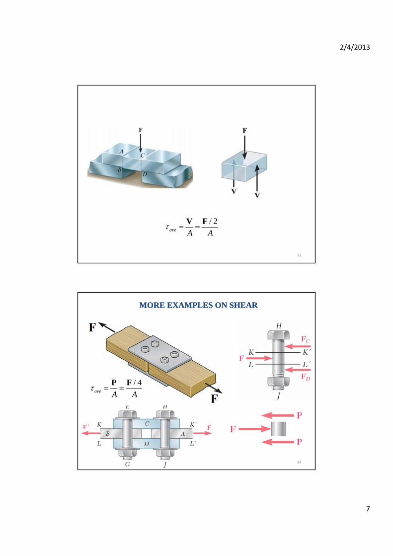
11..6 6 SHEARING STRESSSHEARING STRESS
Transverse load is actingperpendicular to the rod (not inthe normal direction).
ave A A
P F
The load cause shear stress.
12
2/4/2013
7
/ 2ave A A
V F
13
MORE EXAMPLES ON SHEARMORE EXAMPLES ON SHEAR
/ 4ave A A
P F
14

2/4/2013
8
Example: given width w = 150 mm. Find the average shear stress along sections a-a and b-b.
Solution:
15
Find and in order to
support the 20kN, given
60 MPa
35 MPaall
all
d t
Example :
16
2/4/2013
9
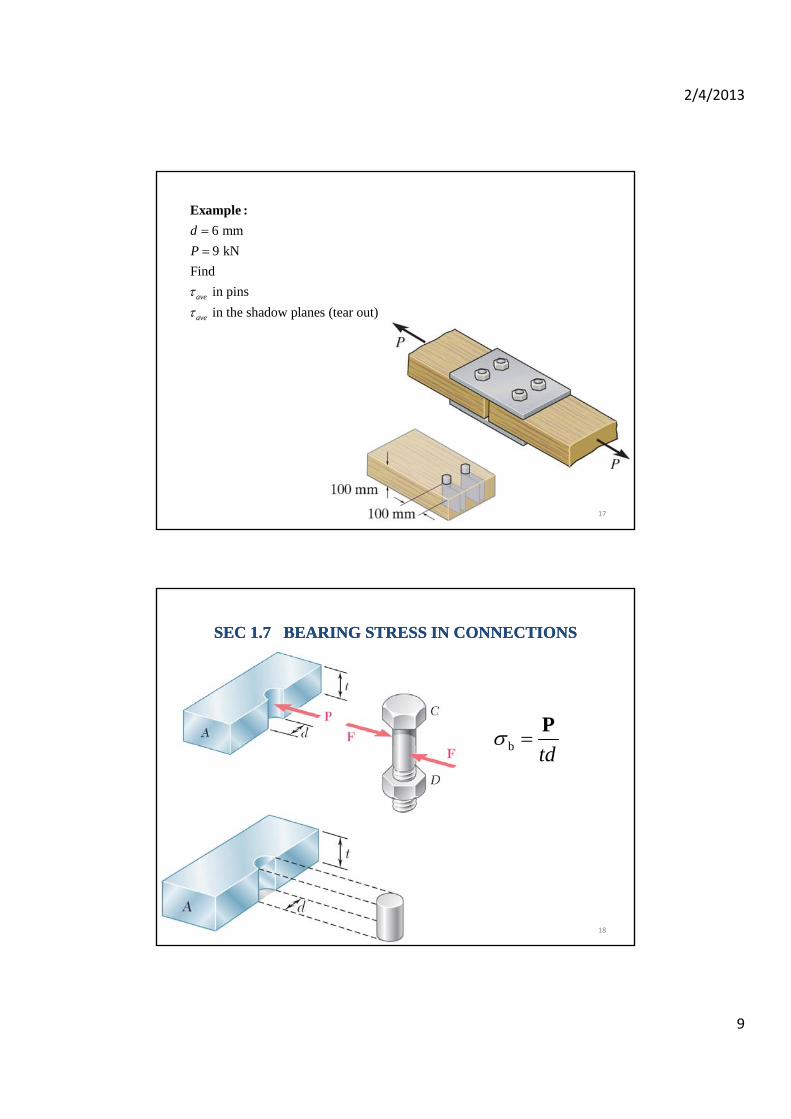
6 mm
9 kN
Find
in pins
d
P
Example :
in pins
in the shadow planes (tear out)ave
ave
17
SEC SEC 11..7 7 BEARING STRESS IN CONNECTIONSBEARING STRESS IN CONNECTIONS
b td
P
18
2/4/2013
10
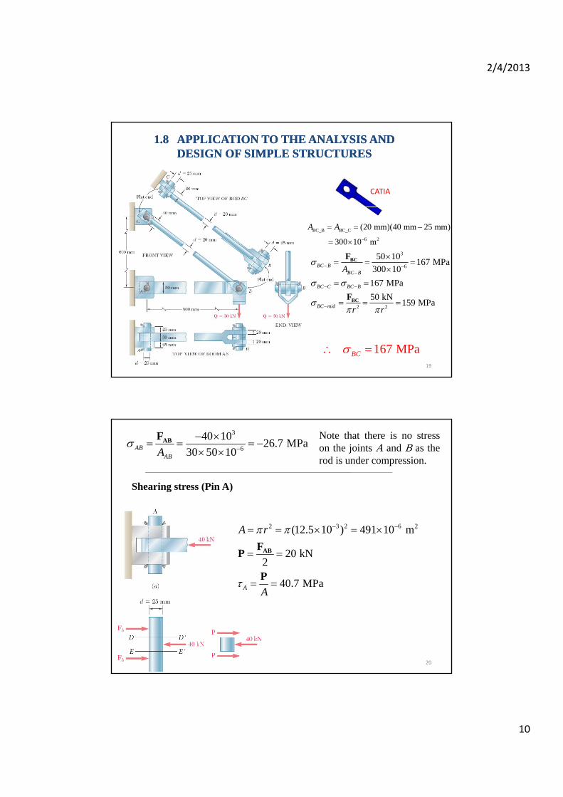
11..8 8 APPLICATION TO THE ANALYSIS AND APPLICATION TO THE ANALYSIS AND DESIGN OF SIMPLE STRUCTURES DESIGN OF SIMPLE STRUCTURES
CATIA
BC_B BC_C
6 2
(20 mm)(40 mm 25 mm)
300 10 m
A A
3
6
50 10167 MPa
300 10
167 MPa
BC BBC B
BC C BC B
A
BCF
2 2
50 kN159 MPaBC mid r r
BCF
167 MPaBC 19
3
6
40 1026.7 MPa
30 50 10ABABA
ABF Note that there is no stress
on the joints A and B as therod is under compression.
Shearing stress (Pin A)
2 3 2 6 2(12.5 10 ) 491 10 m
20 kN2
40.7 MPaA
A r
A
ABFP
PA A
20

2/4/2013
11
2 3 2 6 2(12.5 10 ) 491 10 m
50 kN
A r BCP F
Shearing stress (Pin C)
102 MPaC A
P
21
3
2 6
25 1050.9 MPa
491 10B r
GP
Shearing stress (Pin B)
Bearing stress at point A
3
6
1- on the rod
40 1053.3 MPa
30 25 10b td
P 3
6
2 on the brackets
40 1032.0 MPa
2 25 25 10b td
P
22

2/4/2013
12
EDC is rigid
Given :
9 mm 6 mm each
9 mm 6 mm
Find :
AB BC
A C
t t
d d
Example :
Find :
1 shearing stress at pin .
2 shearing stress at pin .
3 the normal stress at link .
4 shearing stress at .
5 bea
A
C
ABC
B
ring stress in the link at .C
23
24
2/4/2013
13
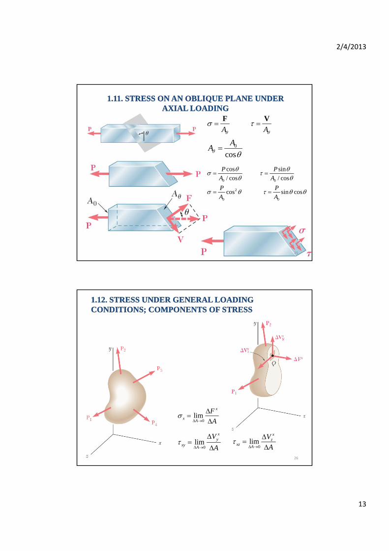
A A
F V
A
11..1111. STRESS ON AN OBLIQUE PLANE UNDER . STRESS ON AN OBLIQUE PLANE UNDER AXIAL LOADINGAXIAL LOADING
0
cos
AA
0 0
2
0 0
cos sin
/ cos / cos
cos sin cos
P P
A A
P P
A A
25
11..1212. STRESS UNDER GENERAL LOADING . STRESS UNDER GENERAL LOADING CONDITIONS; COMPONENTS OF STRESSCONDITIONS; COMPONENTS OF STRESS
0lim
x
xA
F
A
0lim
xy
xy A
V
A
0lim
xz
xz A
V
A
26

2/4/2013
14
27
0; ( ) ( ) 0M A a A a 0; ( ) ( ) 0
also
z xy yx
xy yx
xz zx yz zy
M A a A a
28
2/4/2013
15
1- Determination of the ultimate strength of a material.
11..13 13 DESIGN CONSIDERATIONDESIGN CONSIDERATION
UU
P
A
2- Allowable stress; factor of safety
A
Ultimate stressFactor of safety = F S =Factor of safety = F.S =
Allowable stress
29
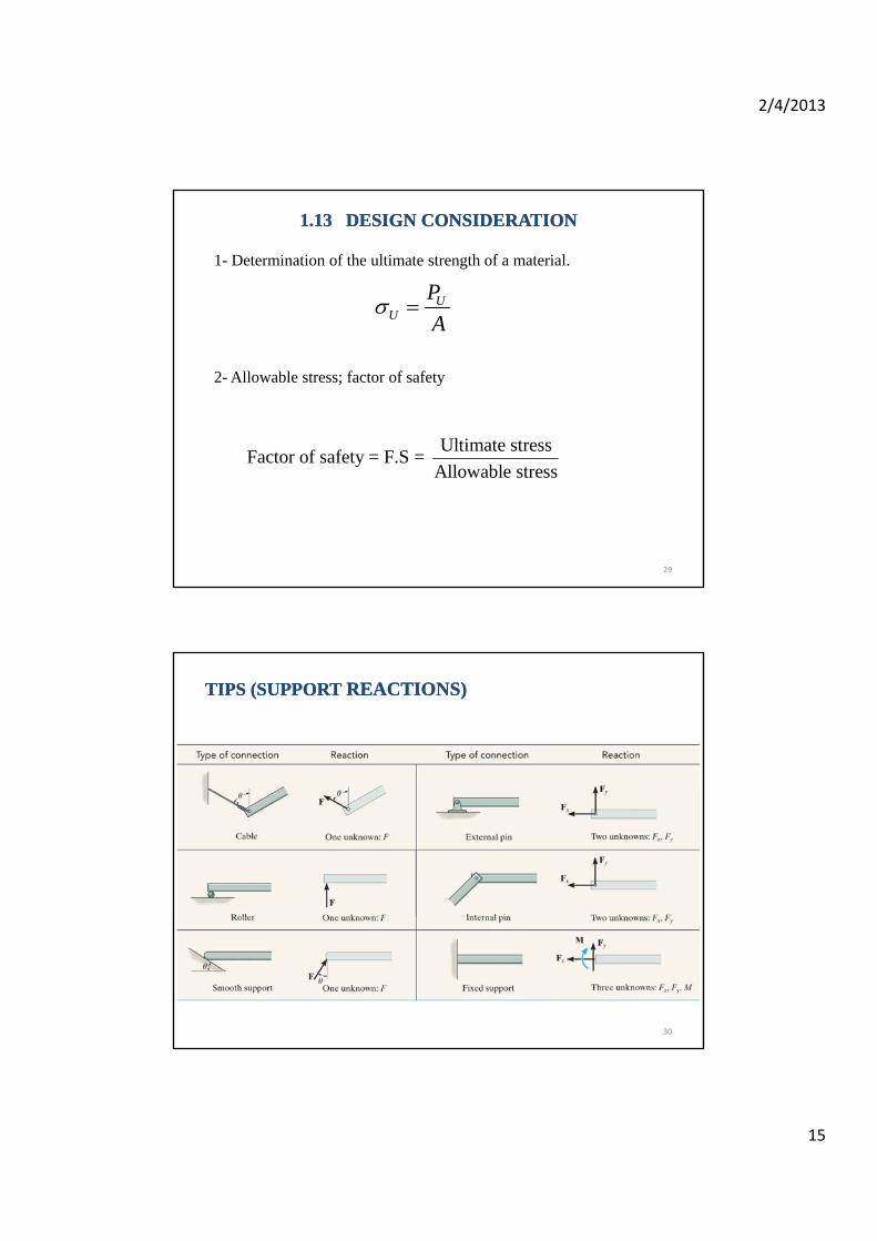
TIPS (SUPPORT TIPS (SUPPORT REACTIONS)REACTIONS)
30
2/4/2013
16
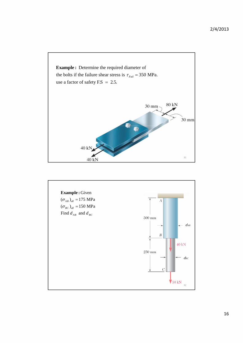
Determine the required diameter of
the bolts if the failure shear stress is 350 MPa.
use a factor of safety F.S 2.5.Fail
Example :
31
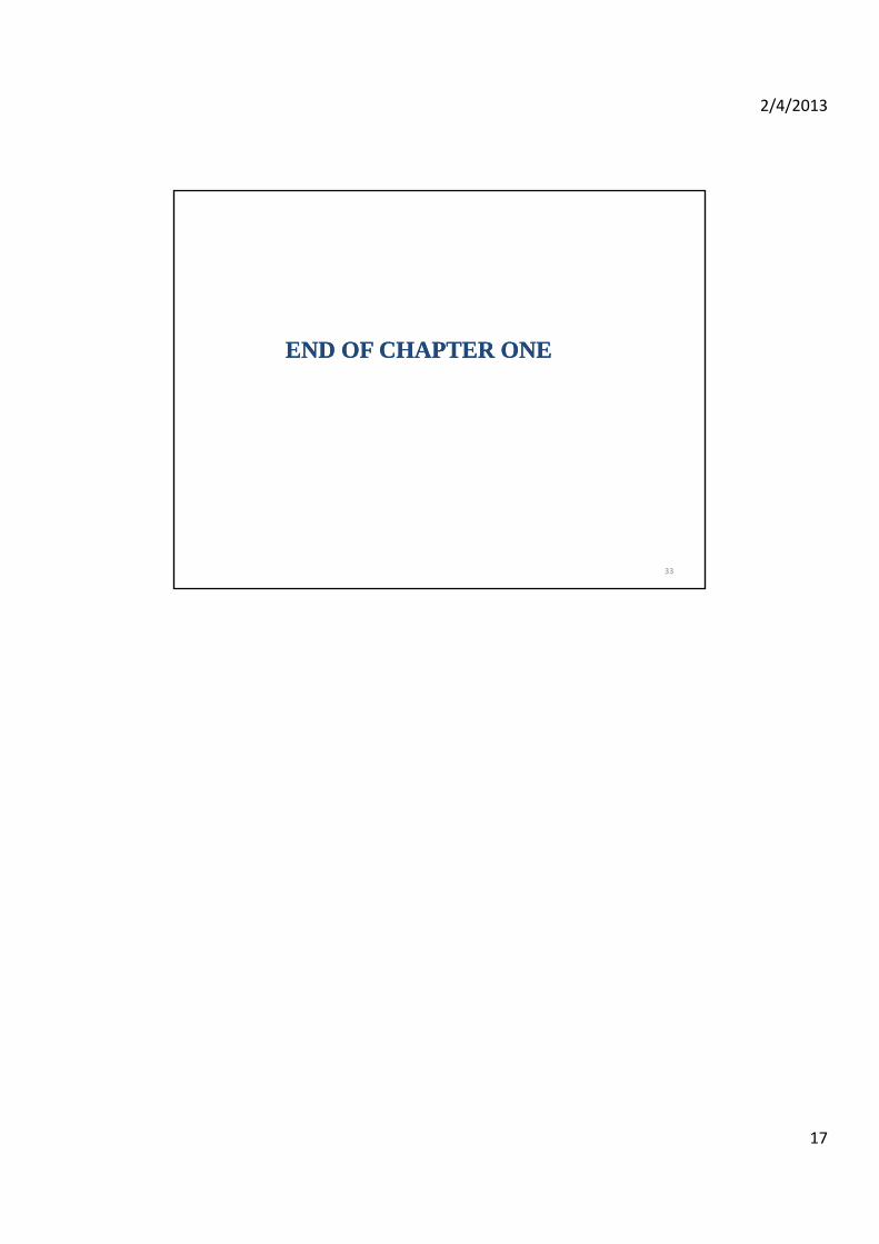
Given
( ) 175 MPa
( ) 150 MPa
Find and
AB all
BC all
AB BCd d
Example :
dAB
dBC
32
2/4/2013
17
END OF CHAPTER END OF CHAPTER ONEONE
33