mechanics of fiber fragmentation in single-fiber · pdf filesingle-fiber composite (sfc),...
TRANSCRIPT
16TH INTERNATIONAL CONFERENCE ON COMPOSITE MATERIALS
1
Abstract
We investigate the fragmentation process in a single-fiber composite (SFC), using a cohesive zone model. The evolution of microscopic damage near a fiber break has been investigated in detail. The results indicate that cohesive parameters for the fiber-matrix interface control the microscopic damage near a fiber break and the fragmentation process. We discuss how the major damage mode near a fiber break transits from interfacial debonding to matrix cracking. The transition to a damage pattern dominated by matrix cracking makes it difficult to use the fragmentation process to evaluate interface properties in an SFC test. The discussion demonstrates that the fiber strength distribution can be obtained by fitting the fragmentation process while the estimation of interfacial properties based on SFC tests becomes difficult because of the damage transition to matrix cracking in the case of strong interface. 1 Introduction
Fiber-reinforced polymer matrix composites have been widely used as load-bearing materials in industries for their superior mechanical and strength properties. To ensure the reliability of the structures composed of these composites, the detailed understanding of the damage behavior in them is required. For the quantitative characterization of the microscopic damages in the composites, single-fiber composite (SFC) has been widely used [1]. In the SFC, a single fiber embedded in the matrix suffers multiple fiber breaks, and the matrix cracks and interfacial debonding stem from them under tension. These damages in SFC may be reasonably related to
those in short or continuous fiber-reinforced composites.
Numerous models have been proposed for the quantitative evaluation of the microscopic damage and fiber fragmentation in SFC. Early models for SFC [2] represented the accumulation of fiber breaks based on the constant interfacial shear stress model neglecting the failure of matrix or interface around fiber breaks. These models estimated the interfacial shear strength from the final distribution of fiber fragmented length. However, recent researches have reported that interfacial debonding [3] or matrix hardening [4] influences the axial stress recovery from fiber breaks, which is a key factor for the fiber fragmentation. On the contrary, some researches focused on the interfacial debonding induced by fiber breaks and predicted its growth by linear fracture mechanics [5]. However, their models cannot describe the detailed plastic deformation of matrix around a fiber break. Therefore, a comprehensive model of microscopic damage and fiber fragmentation in SFC, considering matrix plasticity and the failure of matrix and interface, must be established.
We present a numerical model for the fiber fragmentation in SFC, based on finite element analysis combined with cohesive elements. Moreover, we conduct Monte-Carlo simulations for the fragmentation of the embedded fiber to investigate the influence of the matrix failure and interfacial debonding on the fiber fragmentation. Based on the model, we attempt to quantify the fracture properties (strength and toughness) of the fiber/matrix interface in composites, using the fragmentation process and debonding growth for HI-NicalonTM SiC single-fiber epoxy composite and T300 carbon single-fiber epoxy composite systems.
MECHANICS OF FIBER FRAGMENTATION IN SINGLE-FIBER COMPOSITE
Masaaki Nishikawa*, Tomonaga Okabe**, Nobuo Takeda***
*Department of Aeronautics and Astronautics, The University of Tokyo, **Department of Aerospace Engineering, Tohoku University,
*** Department of Advanced Energy, The University of Tokyo
Keywords: Fiber-reinforced polymer matrix composites, Single-fiber composite, Interface properties, Microscopic damage, Cohesive zone model
MASAAKI NISHIKAWA,Tomonaga Okabe, Nobuo Takeda
2
2 Single-Fiber Composite Model In the SFC, a single fiber embedded in a
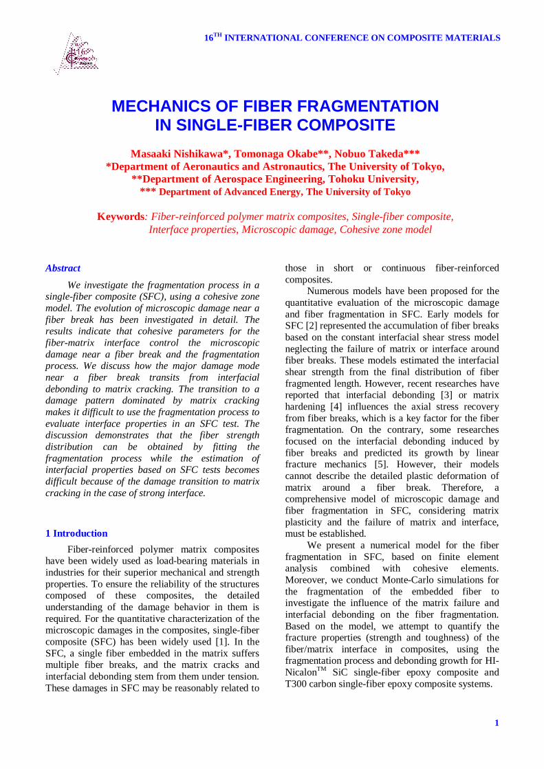
polymer matrix suffers multiple fiber breaks when loaded in tension, with matrix cracks and interfacial debonding forming around the breaks. Figure 1 illustrates typical microscopic damages around a fiber break in SFC. Transverse matrix cracks and/or interfacial debonding between the fiber and matrix emanate from fiber breaks. To investigate the mutual interaction of these microscopic damages, we have developed a micromechanical model as shown in Fig. 2. The analysis considers fiber fragmentation by setting the positions of fiber breaks in the model at regular intervals, as shown in Fig. 2. Fiber breaking is assumed to follow a maximum stress criterion with a Weibull statistical distribution of breaking strengths.
1
00 1
1lnR
Lcr (1)
where is the Weibull modulus, and 0 is the characteristic strength of a fiber with length L0.
Fig. 1. Typical microscopic damages in SFC
Fig. 2. Micromechanical model for SFC
Moreover, the initiation and propagation of matrix cracks and/or interfacial debonding induced by the fiber break is permitted through the incorporation of six-node Dugdale cohesive elements between the solid elements at the corresponding positions. Cohesive elements are interface elements that relate the cohesive traction T across the interface to the interface separation . We recently presented a simple cohesive element constitutive rule for T versus [6, 7] that is based on Dugdale’s assumption, as illustrated in Fig. 3. After the interface traction reaches its maximum value Ti,max (i = I, II), where subscript i denotes the separation mode of the cohesive element, the traction remains constant until complete separation occurs at a critical value ic (i = I, II). The critical separation and maximum traction are related to the critical energy release rate Gic (i = I, II) of the cohesive element as
1
max,
max, 2kT
TG i
i
icic (2)
where k1 denotes the tangent modulus of the intact cohesive elements. Then the parameters of the present cohesive element are constant maximum traction Ti,max and critical energy release rate Gic of each mode (i = I, II).
The model consists of nine-node isoparametric elements for the fiber and matrix. The fiber is modeled as an orthotropic-elastic material while the matrix is assumed to be an isotropic elastic-plastic material. The plastic constitutive behavior of the epoxy matrix is based on J2 flow theory and uses linear-isotropic hardening function.
The incremental analysis is conducted by controlling the end displacement of the model. In order to consider the proper interaction of individual damage, Rmin method is used for the damage process in cohesive elements and matrix yielding.
Fig. 3. Dugdale cohesive element
Cohesive elements for matrix crack
Matrix
Fiber Axisymmetric Fiber breaking positions
Cohesive elements for debonding
Fiber (3.5 m)
Fiber breaking positions
0.2 mm
x
y
Unloading
(a) Normal direction (b) Tangential direction
Relative displacement
Trac
tion
0 cI
IG
max,IT
Contact state
Trac
tion
max,IIT
max,IIT
IIG
IIG
cII
cII
0
Unloading
Relative displacement
Embedded fiber
Matrix
Tensile load 10 mm
Fiber
Matrix Matrix crack
Fiber break
Debonding

3
MECHANICS OF FIBER FRAGMENTATION IN SINGLE-FIBER COMPOSITE
3 Numerical Results for the Microscopic Damage in SFC
This section presents the simulated results of the fragmentation process in an embedded fiber and the microscopic damage near a fiber break (matrix cracking and interfacial debonding) as cohesive parameters for the fiber-matrix interface are varied. The simulation used the material properties of carbon-fiber (T300) and epoxy (Epikote 828 with TETA as curing agent) single-fiber composite.
Figure 3 shows the simulated results when the interface parameters are varied. The stress in the figure is the difference between two principal stresses. Cohesive parameters for the fiber/matrix interface controls the microscopic damage around fiber breaks. While no matrix cracks are initiated and interfacial debonding grows around all fiber breaks, matrix cracks do appear and the debonding growth is greatly suppressed around almost all fiber breaks with the improved interface properties. The damage pattern when interfacial properties are varied is consistent with the experimental observations reported in Ref. [8].
Figure 4 summarizes the simulated results of the number of fiber breaks as a function of the applied strain. When matrix cracks are initiated around some fiber breaks, the initiation of interfacial debonding is suppressed and the fiber fragmentation is not saturated. When the interfacial debonding is dominant, the fiber fragmentation is saturated. This is because the stress recovery length becomes longer as the interfacial debonding grows longer, while the stress recovery length is little influenced by matrix cracking, as demonstrated in our previous study [7].
(a) TII, max = 60 MPa, GIIc = 120 J/m2
(b) TII, max = 150 MPa, GIIc = 300 J/m2
Fig. 3. Simulated microscopic damage patterns
Fig. 4. Simulated results of fiber fragmentation
The simulated results are compared with previous analytical models for fiber fragmentation in Fig. 4. Hui et al. [2] presented a closed-form solution for fiber fragmentation based on the constant shear stress model. In cases where the major damage caused by the fiber break is interfacial debonding, the parameter in the constant shear stress model, which was called ‘interfacial shear strength’, can be chosen so as to be consistent with the simulated results of fiber fragmentation. However, this fitted value of the parameter to explain the fiber fragmentation is physically meaningless. In other work, Okabe et al. [4] proposed an elastoplastic shear-lag model considering the effect of matrix hardening with no interfacial debonding. The present simulation and a Monte-Carlo simulation with the elastoplastic shear-lag model are also compared in Fig. 4, for the case where matrix cracking is the major damage around fiber breaks. The fragmentation process calculated with the present simulation agrees well with the elastoplastic shear-lag model even at a high applied strain.
Finally, Figure 4 reveals that the fiber fragmentation obtained with the present model agrees well with these theoretical models at a low strain where the influence of the microscopic damage around fiber breaks is negligible. Therefore, these theoretical models are still useful for estimating fiber strength distribution. In contrast, to estimate the interfacial parameters, a careful analysis on the fragmentation process and debonding growth is necessary, because the influence of debonding growth on fragmentation process is complicated.

MASAAKI NISHIKAWA,Tomonaga Okabe, Nobuo Takeda
4
4 Determination of Interface Properties from SFC Tests
4.1 Procedure The previous section demonstrated that our
numerical model reproduces the qualitative feature of the microscopic damage near a fiber break and the fragmentation process by controlling the cohesive parameters for the fiber/matrix interface. Therefore, this model will be capable of quantifying the interfacial properties based on SFC tests by comparing the fragmentation process and debonding growth between experiments and simulation.
Based on these results, we propose two types of indicators to characterize the actual cohesive parameters. One is defined based on the number of fiber breaks as follows;
fM
fffsimff
break NNM
e2
exp,, )(~)(1 (3)
where exp,~
fN denotes the averaged debonding length per unit fiber break measured at each sampling strain f in experiments, and simfN , denotes the averaged debonding length calculated from the simulation. The other indicator is defined based on the debonding length as follows;
dM
dddsimdd
debond LLM
e2
exp,, )(~)(1 (4)
where exp,~
dL denotes the averaged debonding length per unit fiber break measured at each sampling strain
d in experiments, and simdL , denotes the averaged debonding length calculated from simulation.
The evaluation of interfacial parameters based on Eq. (3) needs a great care, since the fragmentation process is greatly influenced by the statistical strength parameters of the embedded fiber (see Eq. (1)). The previous section showed that the results with simple shear-lag model for the fragmentation process shows a similar initial rise in the number of fiber breaks to that of the FEM simulation for the same statistical strength parameters for the embedded fiber. Therefore, the present study uses Hui’s theoretical model for the fragmentation process to pre-determine the fiber strength parameters, by obtaining a quantitative fit to the initial rise in the number of fiber breaks in experimental results. Then the indicator of Eq. (3) is compared based on the simulated results with the same set of fiber strength parameters as interfacial parameters are varied in the simulation. When the
cohesive parameters are varied in the simulation, two indicators (Eqs. (3) and (4)) will come to be near zero where the simulated results reproduce the experimental results in terms of the fragmentation process and debonding growth. 4.2 HI-NicalonTM SiC Single-Fiber Composite
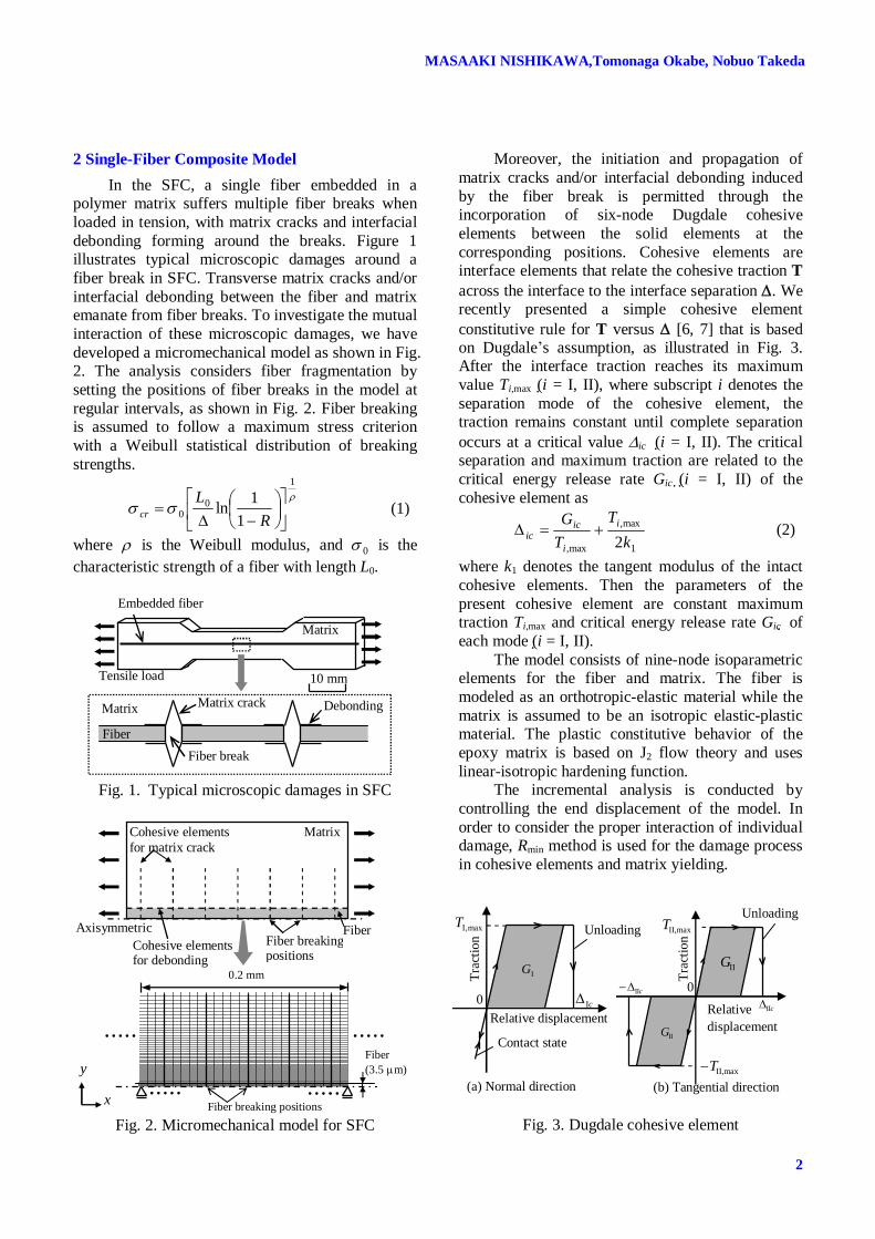
We estimate the interfacial properties for HI-NicalonTM SiC single-fiber epoxy composite based on the proposed method, utilizing our experimental results [3]. To summarize the results as cohesive parameters are varied, an iso-error map is useful to quantify the cohesive parameters of the fiber-matrix interface. Figure 5 shows the isoerror map of breake as interfacial parameters (TII,max, GIIc) are varied. The agreement between the simulated results and experimental results is attained within the range of
03.0breake . Figure 6 compares the number of fiber breaks between simulation and experiment in the case of (TII,max, GIIc)= (75 MPa, 200 J/m2).
Fig. 5. Isoerror map breake for SiC-epoxy system
Fig. 6. Comparison of fragmentation process for SiC-epoxy system
5
MECHANICS OF FIBER FRAGMENTATION IN SINGLE-FIBER COMPOSITE
Fig. 7. Simulated results for SiC-epoxy system
Fig. 8. Isoerror map debonde for SiC-epoxy system. Figure 7 shows the typical simulated result in
the case of (TII,max, GIIc)= (75 MPa, 200 J/m2). The figure illustrates that interfacial debonding is initiated from each fiber break. Then the averaged debonding length per unit fiber break is calculated and the comparison between the simulation and experiment is made in Fig. 8. The simulated results agree well with the experiments within the range of
05.0debonde (mm2). The minimal point of the isoerror map of debonde is around (TII,max, GIIc)= (75 MPa, 200 J/m2), and this is almost consistent with the case of breake in Fig. 5. In this way, the present simulation can be used to quantify the interfacial properties of fiber-reinforced composites. 4.3 T300 Carbon Single-Fiber Composite
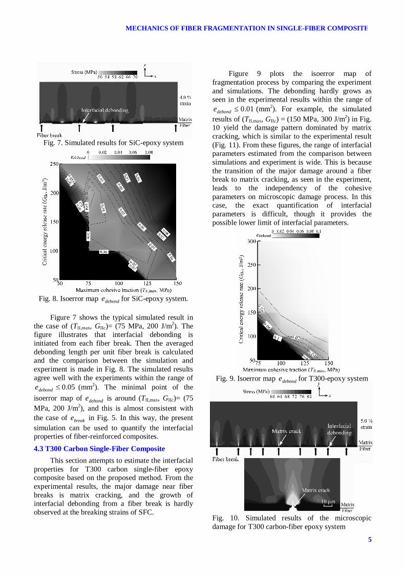
This section attempts to estimate the interfacial properties for T300 carbon single-fiber epoxy composite based on the proposed method. From the experimental results, the major damage near fiber breaks is matrix cracking, and the growth of interfacial debonding from a fiber break is hardly observed at the breaking strains of SFC.
Figure 9 plots the isoerror map of fragmentation process by comparing the experiment and simulations. The debonding hardly grows as seen in the experimental results within the range of
01.0debonde (mm2). For example, the simulated results of (TII,max, GIIc) = (150 MPa, 300 J/m2) in Fig. 10 yield the damage pattern dominated by matrix cracking, which is similar to the experimental result (Fig. 11). From these figures, the range of interfacial parameters estimated from the comparison between simulations and experiment is wide. This is because the transition of the major damage around a fiber break to matrix cracking, as seen in the experiment, leads to the independency of the cohesive parameters on microscopic damage process. In this case, the exact quantification of interfacial parameters is difficult, though it provides the possible lower limit of interfacial parameters.
Fig. 9. Isoerror map debonde for T300-epoxy system
Fig. 10. Simulated results of the microscopic damage for T300 carbon-fiber epoxy system

MASAAKI NISHIKAWA,Tomonaga Okabe, Nobuo Takeda
6
Fig. 11. Experimental results of the microscopic damage for T300 carbon-fiber epoxy system 5 Conclusions
We analyzed the fragmentation process in single-fiber composites, using a cohesive zone model. The evolution of microscopic damage near a fiber break was investigated in detail. Then we attempted to quantify the interface properties for HI-NicalonTM SiC fiber-epoxy and T300 carbon fiber-epoxy composite systems. The conclusions are given below. (1) Cohesive parameters for the fiber-matrix interface control the microscopic damage near a fiber break. When the interface is weak, the major damage is debonding at the interface. In this case, the number of fiber breaks tends to become saturated as the applied stress increases. If the interface is strong, the major damage is matrix cracking emanating from a fiber break. In this case, the number of fiber breaks continues to increase with increasing applied stress. (2) The fragmentation process predicted by previous analytical models (i.e. the constant shear stress model [2] and the elastoplastic shear-lag model [4]) agrees well with that of the present simulation at a low applied strain where the microscopic damage around a fiber break is negligible. (3) For HI-NicalonTM SiC single-fiber epoxy composite, where the major damage near a fiber break is interfacial debonding, interface properties were reasonably determined as (TII,max, GIIc)= (75 MPa, 200 J/m2). For T300 carbon single-fiber epoxy composite, we could not specify the unique interfacial properties, because any cohesive parameters of the interface above the transition line can reasonably explain the fragmentation process in SFC. This difficulty is caused by the transition to the damage pattern dominated by matrix cracking.
Acknowlegement One of the authors (M.N.) was supported
through the 21st Century COE Program, “Mechanical Systems Innovation,” by the Ministry of Education, Culture, Sports, Science and Technology. M.N. acknowledges the support of the Ministry of Education, Culture, Sports, Science and Technology of Japan under Grants-in-Aid for Scientific Research (No. 17-11722).
References [1] Tripathi D. and Jones F.R. “Single fibre
fragmentation test for assessing adhesion in fibre reinforced composites”. Journal of Materials Science, Vol. 33, pp 1-16, 1998.
[2] Hui C.Y. Phoenix S.L. Ibnabdeljalil M. and Smith R.L. “An exact closed form solution for fragmentation of Weibull fibers in a single filament composite with applications to fiber reinforced ceramics”. Journal of the Mechanics and Physics of Solids, Vol. 43, pp 1551-1585, 1995.
[3] Okabe T. and Takeda N. “Estimation of strength distribution for a fiber embedded in single-fiber composite: experiments and statistical simulation based on the elasto-plastic shear-lag approach.” Composites Science and Technology, Vol. 61, pp 1789-1800, 2001.
[4] Okabe T. and Takeda N. “Elastoplastic shear-lag analysis of single-fiber composites and strength prediction of unidirectional multi-fiber composites.” Composites A, Vol. 33, pp 1327-1335, 2002.
[5] Kim B.W. and Nairn J.A. “Observations of fiber fracture and intefacial debonding phenomena using the fragmentation test in single fiber composites.” Journal of Composite Materials, Vol. 36, pp 1825-1834, 2002.
[6] Okabe T. Nishikawa M. and Takeda N. “Numerical simulation of tensile damage evolution in FRP cross-ply laminates.” Transactions of the Japan Society of Mechanical Engineers A, Vol. 72, pp 1254-1261, 2006.
[7] Nishikawa M. Okabe T. and Takeda N. “Characterization of fiber fragmentation in a single-fiber composite in relation to matrix failure and interfacial debonding.” Proceedings of the 12th US-Japan Conference on Composite Materials, pp 774-792, 2006.
[8] Lopattananon N. Kettle A.P. Tripathi D. Beck A.J. Duval E. France R.M. Short R.D. and Jones F.R. “Interface molecular engineering of carbon-fiber composites”, Composites A, Vol. 30, pp 49-57, 1999.