mechanics of advanced composite structures free vibration
TRANSCRIPT

* Corresponding author. Tel.: +98-913-2058928, Fax: +98-31-33660088
E-mail address: [email protected]
Mechanics of Advanced Composite Structures 4 (2017) 59-73
Semnan University
Mechanics of Advanced Composite Structures
journal homepage: http://MACS.journals.semnan.ac.ir Free Vibration and Buckling Analyses of Functionally Graded
Nanocomposite Plates Reinforced by Carbon Nanotube
R. Moradi-Dastjerdi a*, H. Malek-Mohammadi b a Young Researchers and Elite Club, Khomeinishahr Branch, Islamic Azad University, Khomeinishahr, Iran
b Department of Mechanical Engineering, Bu-Ali Sina University, Hamedan, Iran
P A P E R I N F O
A B S T R A C T
Pa per hist ory:
Received 2016-10-05
Revised 2016-11-18
Accepted 2016-11-19
This paper describes the application of refined plate theory to investigate free vibration and
buckling analyses of functionally graded nanocomposite plates reinforced by aggregated carbon
nanotube (CNT). The refined shear deformation plate theory (RSDT) uses four independent
unknowns and accounts for a quadratic variation of the transverse shear strains across the
thickness, satisfying the zero traction boundary conditions on the top and bottom surfaces of the
plate without using shear correction factors. The motion equations are derived from Hamilton’s
energy principle and Navier’s method is applied to solve this equation. The material properties
of the functionally graded carbon nanotube reinforced composites (FG-CNTRCs) are assumed to
vary along the thickness and estimated with the Mori–Tanaka approach. Effects on the natural
frequency and critical buckling load of the FG-CNTRC plates by CNT volume fraction, CNT distri-
bution, CNT cluster distribution, and geometric dimensions of the plate are investigated. Effects
of loading conditions on the critical buckling load are also examined.
Keyw ord s:
Mori–Tanaka approach
Refined plate theory
Aggregated carbon nanotubes
Free vibration
Buckling
DOI: 10.22075/MACS.2016.496 © 2017 Published by Semnan University Press. All rights reserved.
1. Introduction
Carbon nanotubes (CNTs), a new type of ad-vanced material, have attracted a great deal of in-terest from researchers. Because of their extremely attractive mechanical, electrical and thermal prop-erties, CNTs show promising application in polymer composites as a potential reinforcement and multi-functional element [1,2]. The introduction of CNTs into a polymer matrix may therefore greatly im-prove mechanical properties, such as tensile strength and elastic modulus, of the resulting nano-composites [3]. Molecular dynamics (MD) is one technique that can be used to study CNTs. Han and Elliott [4] successfully used the MD method to de-termine the elastic modulus of composite structures under CNT reinforcement, and they investigated the effect of CNT volume fraction on mechanical proper-ties of nanocomposites. They also investigated the effect of CNT waviness on the elastic properties and
mechanical behavior of carbon nanotube reinforced composites (CNTRCs). Alian et al. [5] used a mul-tiscale modeling technique to determine the effec-tive elastic moduli of nanocomposite reinforced by agglomerated carbon nanotubes. Their results showed that the effective elastic properties of the nanocomposite decreased by increasing in CNT vol-ume that is located in CNT clusters. The significant effect of CNT waviness on the load transfer and ac-tive constrained layer damping behavior of the short fuzzy fiber-reinforced composite has been investigated [6-8]. Wuite and Adali [9] used a multi-scale analysis to study the effects of volume, diame-ter and distribution of CNTs on deflection and static behavior of CNTRC beams. Formica et al. [10] pre-sented the vibration behavior of CNTRC plates by employing an equivalent continuum model based on the Mori–Tanaka approach. They found that the im-provement in modal properties achieved a maxi-mum when the carbon nanotubes were uniformly
60 R. Moradi-Dastjerdi & H. Malek-Mohammadi / Mechanics of Advanced Composite Structures 4 (2017) 59-73
aligned along the loading direction. Vodenitcharova and Zhang [11] used the Airy stress-function meth-od to experimentally and computationally investi-gate pure bending and bending-induced local buck-ling of a nanocomposite beam reinforced by a single walled carbon nanotube (SWCNT).
Functionally graded materials (FGMs) are inho-mogeneous composites characterized by smooth and continuous variations in both compositional profile and material properties. Such excellent quali-ties allow them to be fabricated as different struc-tures in accordance with various service require-ments. To obtain the required optimum perfor-mance, the gradient variation of material properties can be achieved by gradually changing the volume fraction of the constituent materials. Reddy [12] presented static and dynamic analyses of the FGM plates based on third order shear deformation theo-ry and by using the theoretical formulation and fi-nite element models. Zenkour [13] presented a two dimensional solution to study the bending, buckling, and free vibration of simply supported FG ceramic–metal sandwich plates. Cheng and Batra [14] used first and third order shear deformation theories to report deflections of a simply supported functional-ly graded polygonal plate. Also, Cheng and Batra [15] studied the buckling and steady state vibra-tions of a simply supported functionally graded po-lygonal plate based on Reddy’s plate theory. Amabili et al. [16] compared Von Kárman, and first (FSDT) and third order shear deformation theories for non-linear vibration analysis of rectangular laminated composite plates with different boundary condi-tions, revealing that FSDT (with shear correction
factor of √3/2) and the higher-order shear defor-mation theory give practically coincident results. Khorshidi et al. [17-18] analyzed vibration behav-iour of laminated composite and functionally graded plates in contact with a bounded fluid using the Ray-leigh–Ritz method and Fourier series. Also, vibra-tional behavior of single and multi-directional FG annular plates and laminated curved panels was investigated using three-dimensional elasticity the-ory and generalized differential quadrature method (GDQM)[19-22].
Using the concept of FGM, CNTs can be distribut-ed in certain grading profiles through certain direc-tions to improve the mechanical properties and to reinforce the composite structures. The composites, which are reinforced by CNTs with grading distribu-tion, are called functionally graded carbon nano-tube-reinforced composites (FG-CNTRCs). Shen [23] suggested that the interfacial bonding strength can be improved with the use of a graded distribution of CNTs in the matrix. He investigated postbuckling of functionally graded nanocomposite cylindrical shells reinforced by CNTs subjected to axial com-
pression in a thermal environment, and showed that the linear functionally graded reinforcements can increase the buckling load. He estimated mechanical properties with a micro-mechanical model in vol-ume fraction form with CNT efficiency parameters. Mehrabadi et al. [24] discussed mechanical buckling behavior of FG nanocomposite plates reinforced by SWCNTs based on the first-order shear deformation theory (FSDT) and mindlin plate theory. However, the rule of mixture is not applicable when straight CNTs are oriented randomly in the matrix. In these cases the Mori–Tanaka approach [25] is one of the best known analytical approaches to accurately de-termine the effective material constants of compo-site materials. Yas and Heshmati [26] used the Mo-ri–Tanaka approach to study the vibrational proper-ties of FG-nanocomposite beams reinforced by ran-domly oriented straight CNTs under the action of moving load. Sobhani Aragh et al. [27] presented vibrational behavior of continuously graded CNT–reinforced cylindrical panels based on the Eshelby–Mori–Tanaka approach. They used the 2D GDQM to discretize the governing equations and to imple-ment the boundary conditions. Pourasghar et al. [28] and Moradi-Dastjerdi et al. [29] performed a free vibration analysis of FG nanocomposite cylin-ders reinforced by randomly oriented straight and locally aggregated CNTs, based on both three-dimensional theory of elasticity, and mesh-free methods. Both teams estimated material properties of FG- CNTRCs with the Eshelby–Mori–Tanaka ap-proach. Finally, vibrational behavior of single and multi-directional nanocomposite FG-CNTRC thick plates, sandwich curved panels and annular plates resting on a Pasternak elastic foundation, were in-vestigated using three-dimensional elasticity theory and GDQM [30-34].
Since FSDT violates the equilibrium conditions on the top and bottom surfaces of the plate, a shear correction factor is required to compensate for the error because of a constant shear strain assumption throughout the thickness. The shear correction fac-tor not only depends on the material and its geo-metric properties, but also on its loading and boundary conditions. Although the FSDT provides a sufficiently accurate description of response for thin to moderately thick plates, it is not convenient to use because of the difficulty in determining the cor-rect value of the shear correction factor. To avoid the use of a shear correction factor, many refined shear deformation plate theories (RSDTs) have been developed including the sinusoidal shear defor-mation plate theory (SSDT) [35-36], RSDT [37-38], and hyperbolic shear deformation plate theory (HSDT) [39-41]. RSDT is based on an assumption that the in-plane and transverse displacements con-sist of bending and shear components in which the

R. Moradi-Dastjerdi & H. Malek-Mohammadi / Mechanics of Advanced Composite Structures 4 (2017) 59-73 61
bending components do not contribute toward shear forces and, likewise, the shear components do not contribute toward bending moments. The mo-tion equation can be derived from Hamilton’s ener-gy principle and Navier’s method solves this equa-tion. Moradi-Dastjerdi et al. [42] used an RSDT with only four independent unknowns, and presented the free vibration analysis of sandwich plates with FG randomly oriented CNTRC face sheets resting on an elastic foundation. Khorshidi et al. [43-44] used nonlocal elasticity theory based on exponential shear deformation theory, for free vibration and buckling analyses of the FG rectangular nanoplates. They also used refined trigonometric shear defor-mation plate theory to study the out-of-plane vibra-tion of the rectangular isotropic plates with differ-ent boundary conditions [45].
Although several studies of the free vibration or buckling of FG and FG nanocomposite plates have been carried out based on a variety of plate theories, no studies can be found applying these analyses to aggregated CNT reinforced plates. In this study, the RSDT is developed to investigate the free vibration and buckling analyses of simply supported function-ally graded nanocomposite plates reinforced by ag-gregated single-walled carbon nanotubes (SWCNTs). The applied nanocomposite is assumed a mixture of CNTs (randomly oriented and locally ag-gregated into some clusters) that are embedded in a polymer. The material properties of the nanocom-posite plates are assumed to vary along the thick-ness of plate and estimated though the Mori–Tanaka method because of its simplicity and accuracy even at a high volume fraction of inclusions. Effects on the natural frequency and critical buckling load of the FG-CNTRC plates by CNT volume fraction, CNT dis-tribution, CNT cluster distribution, and geometric dimensions of the plate are investigated. Effects of loading conditions on the critical buckling load are also examined.
2. Material Properties in FG-CNTRC Rein-forced Composite
Consider a CNTRC is made from a mixture of
SWCNT (that randomly oriented and locally aggre-gated into some clusters) and matrix which is as-sumed to be isotropic. Many studies have been pub-lished each with a different focus on mechanical properties of polymer nanotube composites. How-ever, the common theme has been enhancement of Young’s modulus. In this section, the effective me-chanical properties of the CNT reinforced composite that straight CNTs are oriented randomly, or locally aggregated in to some clusters, are obtained based on the Eshelby–Mori–Tanaka approach. The result-ing effective properties for these CNT reinforced composites are isotropic, despite the CNTs being transversely isotropic. 2.1 Composites reinforced with randomly oriented, straight CNTs
In this section, the effective mechanical proper-ties of composites with randomly oriented nonclus-tered CNTs (as shown in Fig. 1) are studied. The ori-entation of a straight CNT is characterized by two Euler angles α and β, as shown in Fig. 1. When CNTs are completely randomly oriented in the matrix, the composite is isotropic, and its bulk modulus K and shear modulus G are derived as [46]:
(1)
where subscripts m and r are referred to matrix and CNT respectively, f is volume fraction and also,
(2)
(3)
(4)
(5)
)(3
)3(
rrm
rmrrm
ff
KfKK
)(2
)2(
rrm
rmrrm
ff
GfGG
rm
rrmmr
kG
lkGK
3
3
rm
rmmrrrrr
kG
lGKlkln
2322
3
1
mmrmmm
mmmmmm
rm
m
rm
rrmr
GKmGKG
GKGGKG
pG
G
kG
lkG
733
73324
3
24
5
1
rm
rmrr
mrmmrm
mmmr
rm
rmrrr
kG
lGlk
GmGGmK
GKGm
pG
pGln
3
22
73
4388
3
2
5
1

62 R. Moradi-Dastjerdi & H. Malek-Mohammadi / Mechanics of Advanced Composite Structures 4 (2017) 59-73
, 0 , 1cluster
cluster r
r
V V
V V
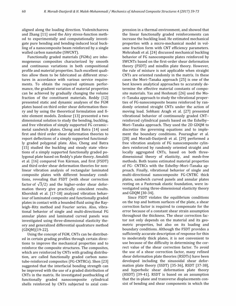
Figure 1. Representative volume element (RVE) with randomly oriented, straight CNTs.
kr, lr, mr, nr, and pr are the Hill’s elastic moduli for the reinforcing phase (CNTs). As mentioned before, the CNTs are transversely isotropic and have a stiffness matrix given below (Hill’s elastic moduli):
(6)
1
100000
01
0000
001
000
0001
0001
0001
LT
ZL
TZ
ZT
TZ
L
LZ
Z
ZT
TL
LT
T
ZL
T
TL
L
r
G
G
G
EEE
EEE
EEE
C
(7)
where EL, ET, EZ, GTZ, GZL, GLT, TZ , ZL and LT are
material properties of the CNT reinforced composite which can be determined from the inverse of the rule of mixture.
So, the effective Young’s modulus E and Pois-son’s ratio of the composite is given by:
(8)
(9)
2.2 Effect of CNT aggregation on the properties of the composite
The CNTs were arranged within the matrix to in-troduce clustering. Because of a large aspect ratio (usually >1000), a low bending rigidity, and Van der Waals forces, CNTs have a tendency to bundle or cluster together making it quite difficult to produce fully-dispersed CNT reinforced composites. The ef-fect of nanotube aggregation on the elastic proper-ties of randomly oriented CNTRCs is presented in
this section. Shi et al. [46] derived a two parameter micromechanics model to determine the effect of nanotube agglomeration on the elastic properties of a randomly oriented CNTRC (Fig. 2). It is assumed that a number of CNTs are uniformly distributed throughout the matrix and that other CNTs appear in cluster form because of aggregation, as shown in Fig. 2. The total volume of the CNTs in the repre-sentative volume element (RVE), denoted by Vr, can be divided into the following two parts:
(10)
where 𝑉𝑟𝑐𝑙𝑢𝑠𝑡𝑒𝑟 denotes the volumes of CNTs inside a
cluster, and 𝑉𝑟𝑚 is the volume of CNTs in the matrix
and outside the clusters. The two parameters used to describe the aggregation are defined as:
(11)
where V is the volume of RVE, Vcluster is the volume of clusters in the RVE. 𝜇 is the volume fraction of clus-ters with respect to the total volume V of the RVE, η is the volume ratio of the CNTs inside the clusters over the total CNT inside the RVE. When 𝜇 = 1, there is uniform distribution of nanotubes through-out the entire composite without aggregation; with a decreasing 𝜇, the agglomeration degree of CNTs becomes more severe. When 𝜂 = 1, all nanotubes are located in the clusters. The case 𝜂 = 𝜇 means that the volume fraction of CNTs inside the clusters is equal to that of CNTs outside the clusters, so all CNTs are located and randomly oriented as in Fig. 1. Thus, we consider the CNT-reinforced composite as a system consisting of spherically shaped clusters in a matrix. We first estimate the effective elastic stiff-ness of the clusters and the matrix respectively, and then calculate the overall property of the whole composite system. The effective bulk modulus Kin and shear modulus Gin of the cluster can be calculat-ed with Prylutskyy et al. [47]:
(12)
(13)
Figure 2. RVE with functionally graded Eshelby cluster model of aggregation of CNTs.
r
r
r
rrrrr
rrrrr
rrr
r
p
m
p
mkmkl
mkmkl
lln
C
00000
00000
00000
000
000
000
GK
KGE
3
9
3 2
6 2
K G
K G
cluster mr r rV V V
rrr
rmrrmin
ff
KfKK
3
3
rrr
rmrrmin
ff
GfGG
2
2
R. Moradi-Dastjerdi & H. Malek-Mohammadi / Mechanics of Advanced Composite Structures 4 (2017) 59-73 63
and the effective bulk modulus Kout and shear modu-lus Gout of the matrix outside the cluster can be cal-culated by:
(14)
(15)
Finally, the effective bulk modulus K and the effec-tive shear modulus G of the composite are derived from the Mori-Tanaka method as follows:
(16)
(17)
with
(18)
(19)
(20)
The effective Young’s modulus E and Poisson’s ratio of the composite can be calculated in the terms of
K and G by Eqs. (8) and (9).
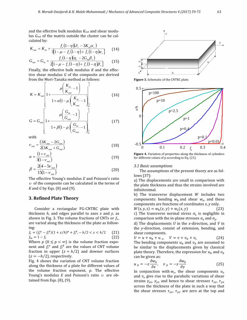
3. Refined Plate Theory
Consider a rectangular FG-CNTRC plate with thickness h, and edges parallel to axes x and y, as shown in Fig. 3. The volume fractions of CNTs or 𝑓𝑟 , are varied along the thickness of the plate as follow-ing: 𝑓𝑟 = (𝑓𝑟
𝑢 − 𝑓𝑟𝑑)(1 + 𝑧 ℎ⁄ )𝑝 + 𝑓𝑟
𝑑 , − ℎ 2⁄ < 𝑧 < ℎ 2⁄ (21) 𝑓𝑚 = 1 − 𝑓𝑟 (22) Where p (0 ≤ 𝑝 < ∞) is the volume fraction expo-nent and 𝑓𝑟
𝑢 and 𝑓𝑟𝑑 are the values of CNT volume
fraction in upper (𝑧 = ℎ 2⁄ ) and downer surfaces (𝑧 = −ℎ 2⁄ ), respectively. Fig. 4 shows the variation of CNT volume fraction along the thickness of a plate for different values of the volume fraction exponent, p. The effective Young’s modulus E and Poisson’s ratio are ob-
tained from Eqs. (8), (9).
Figure 3. Schematic of the CNTRC plate.
Figure 4. Variation of properties along the thickness of cylinders for different values of p according to Eq. (21).
3.1 Basic assumptions The assumptions of the present theory are as fol-
lows [37]: a) The displacements are small in comparison with the plate thickness and thus the strains involved are infinitesimal. b) The transverse displacement 𝑊 includes two components: bending 𝑤b and shear 𝑤s, and these components are functions of coordinates x, y only. 𝑊(x, y, z) = 𝑤b(𝑥, 𝑦) + 𝑤s(𝑥, 𝑦) (23) c) The transverse normal stress 𝜎z is negligible in comparison with the in-plane stresses 𝜎x and 𝜎y.
d) The displacements U in the x-direction, and V in the y-direction, consist of extension, bending, and shear components. 𝑈 = 𝑢 + 𝑢𝑏 + 𝑢 𝑠, 𝑉 = 𝑣 + 𝑣𝑏 + 𝑣𝑠 (24) The bending components 𝑢𝑏 and 𝑣𝑏 are assumed to be similar to the displacements given by classical plate theory. Therefore, the expression for 𝑢𝑏 and 𝑣𝑏 can be given as:
𝑢 𝑏 = −𝑧𝜕𝑤𝑏𝜕𝑥
, 𝑣 𝑏 = −𝑧𝜕𝑤𝑏𝜕𝑦
(25)
In conjunction with 𝑤𝑠 , the shear components 𝑢𝑠 and 𝑣𝑠 give rise to the parabolic variations of shear strains 𝛾𝑥𝑧 , 𝛾𝑦𝑧 and hence to shear stresses 𝜏𝑥𝑧 , 𝜏𝑦𝑧
across the thickness of the plate in such a way that the shear stresses 𝜏𝑥𝑧 , 𝜏𝑦𝑧 are zero at the top and
rrr
rmrrmout
ff
KfKK
1113
31
rrr
rmrrmout
ff
GfGG
1112
21
111
1
1
out
in
out
in
out
K
K
K
K
KK
111
1
1
out
in
out
in
out
G
G
G
G
GG
outout
outoutout
GK
GK
32
23
out
out
13
1
out
out
115
542
0 0.1 0.2 0.3 0.4-0.5
0
0.5
fr
z/h
p=10
p=100
p=0.01
p=2.5
p=1
p=0.4
p=0.1

64 R. Moradi-Dastjerdi & H. Malek-Mohammadi / Mechanics of Advanced Composite Structures 4 (2017) 59-73
bottom faces of the plate. Consequently, the expres-sion for 𝑢𝑠 and 𝑣𝑠 can be given as:
𝑢 𝑠 = [1
4𝑧 −
5
3𝑧 (𝑧
ℎ)2
]𝜕𝑤𝑠𝜕𝑥
,
𝑣 𝑠 = [1
4𝑧 −
5
3𝑧 (𝑧
ℎ)2
]𝜕𝑤𝑠𝜕𝑦
(26)
3.2 Kinematics and constitutive equations Based on the assumptions made in the preceding
section, the displacement field can be obtained [37]
𝑢(𝑥, 𝑦, 𝑧) = 𝑢0(𝑥, 𝑦) − 𝑧𝜕𝑤𝑏𝜕𝑥
− 𝑓(𝑧)𝜕𝑤𝑠𝜕𝑥
𝑣(𝑥, 𝑦, 𝑧) = 𝑣0(𝑥, 𝑦) − 𝑧𝜕𝑤𝑏𝜕𝑦
− 𝑓(𝑧)𝜕𝑤𝑠𝜕𝑦
𝑤(𝑥, 𝑦, 𝑧) = 𝑤𝑏(𝑥, 𝑦) + 𝑤𝑠(𝑥, 𝑦)
(27)
where
𝑓(𝑧) = 𝑧[−1
4+5
3(𝑧
ℎ)2] (28)
The strains associated with the displacements in Eq. (27) are: 휀𝑥 = 휀𝑥
0 + 𝑧𝑘𝑥𝑏 + 𝑓(𝑧)𝑘𝑥
𝑠 , 휀𝑦 = 휀𝑦
0 + 𝑧𝑘𝑦𝑏 + 𝑓(𝑧)𝑘𝑦
𝑠
𝛾𝑥𝑦 = 𝛾𝑥𝑦0 + 𝑧𝑘𝑥𝑦
𝑏 + 𝑓(𝑧)𝑘𝑥𝑦𝑠
𝛾𝑦𝑧 = 𝑔(𝑧)𝛾𝑦𝑧𝑠 , 𝛾𝑥𝑧 = 𝑔(𝑧)𝛾𝑥𝑧
𝑠
휀𝑧 = 0
(29)
where
휀𝑥0 =
𝜕𝑢0𝜕𝑥
, 𝑘𝑥𝑏 = −
𝜕2𝑤𝑏𝜕𝑥2
, 𝑘𝑥𝑠 = −
𝜕2𝑤𝑠𝜕𝑥2
휀𝑦0 =
𝜕𝑣0𝜕𝑦
, 𝑘𝑦𝑏 = −
𝜕2𝑤𝑏𝜕𝑦2
, 𝑘𝑦𝑠 = −
𝜕2𝑤𝑠𝜕𝑦2
γxy0 =
∂u0∂y
+∂v0∂x
, 𝑘𝑥𝑦𝑏 = −2
𝜕2𝑤𝑏𝜕𝑥𝜕𝑦
,
𝑘𝑥𝑦𝑠 = −2
𝜕2𝑤𝑠𝜕𝑥𝜕𝑦
𝛾𝑦𝑧𝑠 =
𝜕𝑤𝑠𝜕𝑦
, 𝛾𝑥𝑧𝑠 =
𝜕𝑤𝑠𝜕𝑥
, 𝑔(𝑧) = 1 −𝑑𝑓(𝑧)
𝑑𝑧
(30)
For elastic and isotropic materials, the constitutive relations can be written as:
{
𝜎𝑥𝜎𝑦𝜏𝑥𝑦
} = ⌈
𝑄11 𝑄12 0𝑄12 𝑄22 00 0 𝑄66
⌉ {
휀𝑥휀𝑦𝛾𝑥𝑦}
{𝜏𝑦𝑧𝜏𝑧𝑥} = ⌈[
𝑄44 00 𝑄55
]⌉ {𝛾𝑦𝑧𝛾𝑧𝑥}
(31)
where (𝜎𝑥 , 𝜎𝑦 , 𝜏𝑥𝑦 , 𝜏𝑦𝑧 , 𝜏𝑥𝑧) and (휀𝑥, 휀𝑦, 𝛾𝑥𝑦 , 𝛾𝑦𝑧 , 𝛾𝑧𝑥)
are the stress and strain components, respectively. Using the material properties defined in Eq. (21), stiffness coefficients, 𝑄𝑖𝑗 , can be expressed as:
𝑄11 = 𝑄22 =𝐸(𝑧)
1 − 𝜐2, 𝑄12 =
𝜐 𝐸(𝑧)
1 − 𝜐2,
𝑄66 = 𝑄44 = 𝑄55 =𝐸(𝑧)
2(1 + 𝜐)
(32)
3.3 Governing equations Using Hamilton’s energy principle the motion
equation of the isotropic plate is derived:
𝛿 ∫ (𝑈 + 𝑉 − 𝐾)𝑑𝑡𝑡2
𝑡1
= 0 (33)
where 𝑈 is the strain energy, 𝑉 work done by ap-plied forces, and 𝐾 is the kinetic energy of the iso-tropic plate. Employing the minimum of the total energy principle leads to a general equation of mo-tion and boundary conditions. Taking the variation of the above equation and integrating by parts:
∫ [∫ 𝜎𝑥𝛿𝜖𝑥 + 𝜎𝑦𝛿𝜖𝑦 + 𝜏𝑥𝑦𝛿𝛾𝑥𝑦 + 𝜏𝑦𝑧𝛿𝛾𝑦𝑧𝑣
𝑡2
𝑡1
+ 𝜏𝑧𝑥𝛿𝛾𝑧𝑥 − 𝜌(�̈�𝛿𝑢 + �̈�𝛿𝑣 + �̈�𝛿𝑤)]𝑑𝑣
+∫ (𝑁𝑥0(𝛿𝑤𝑏,𝑥 + 𝛿𝑤𝑠,𝑥) + 𝑁𝑦
0(𝛿𝑤𝑏,𝑦𝐴
+ 𝛿𝑤𝑠,𝑦))𝑑𝐴]𝑑𝑡 = 0
(34)
where ̈ represents the second derivative with re-spect to time and also (𝑁𝑥
0, 𝑁𝑦0 ) are in-plane pre-
buckling forces. The equations of motion can be obtained by substi-tution of Eqs. (27) and (29) into Eq. (34) and by consideration of the following assumptions. The stress resultants 𝑁, 𝑀, 𝑆 and the mass moments of inertia are defined by:
[
𝑁𝑥 𝑁𝑦 𝑁𝑥𝑦
𝑀𝑥𝑏 𝑀𝑦
𝑏 𝑀𝑥𝑦𝑏
𝑀𝑥𝑠 𝑀𝑦
𝑠 𝑀𝑥𝑦𝑠
] = ∫ (𝜎𝑥 , 𝜎𝑦 , 𝜏𝑥𝑦) (1𝑧
𝑓(𝑧))𝑑𝑧
ℎ
2
−ℎ
2
(35.a)
(𝑠𝑥𝑧𝑠 , 𝑠𝑦𝑧
𝑠 ) = ∫ (𝜏𝑥𝑧 , 𝜏𝑦𝑧)𝑔(𝑧)𝑑𝑧
ℎ
2
−ℎ
2
(35.b)
(𝐼1, 𝐼2, 𝐼3, 𝐼4, 𝐼5, 𝐼6)
= ∫ 𝜌(𝑧)(1, 𝑧, 𝑧2, 𝑓(𝑧), 𝑧𝑓(𝑧), (𝑓(𝑧))2)𝑑𝑧
ℎ
2
−ℎ
2
(35.c)
So, the equation of motion can be written as: 𝛿𝑢0: 𝑁𝑥,𝑥 + 𝑁𝑥𝑦,𝑦 = 𝐼2�̈�𝑏,𝑥 + 𝐼4�̈�𝑠,𝑥 − 𝐼1�̈�0 (36.a) 𝛿𝑣0: 𝑁𝑦,𝑦 +𝑁𝑥𝑦,𝑥 = 𝐼2�̈�𝑏,𝑦 + 𝐼4�̈�𝑠,𝑦 − 𝐼1�̈�0 (36.b) 𝛿𝑤𝑏: 𝑀𝑥,𝑥𝑥
𝑏 +𝑀𝑦,𝑦𝑦𝑏 + 2𝑀𝑥𝑦,𝑥𝑦
𝑏 + 𝑝(𝑤)
= 𝐼3(�̈�𝑏,𝑥𝑥 + �̈�𝑏,𝑦𝑦) + 𝐼5(�̈�𝑠,𝑥𝑥 + �̈�𝑠,𝑦𝑦)
− 𝐼2(�̈�0,𝑥 + �̈�0,𝑦) − 𝐼1(�̈�𝑏 + �̈�𝑠)
(36.c)
𝛿𝑤𝑠: 𝑀𝑥,𝑥𝑥𝑠 +𝑀𝑦,𝑦𝑦
𝑠 + 2𝑀𝑥𝑦,𝑥𝑦𝑠 + 𝑠𝑦𝑧,𝑦
𝑠
+ 𝑠𝑥𝑧,𝑥𝑠 + 𝑝(𝑤)
= 𝐼5(�̈�𝑏,𝑥𝑥 + �̈�𝑏,𝑦𝑦) + 𝐼6(�̈�𝑠,𝑥𝑥 + �̈�𝑠,𝑦𝑦)
− 𝐼4(�̈�0,𝑥 + �̈�0,𝑦) − 𝐼1(�̈�𝑏 + �̈�𝑠)
(36.d)
where 𝑝(𝑤)
= 𝑁𝑥0(𝑤𝑏,𝑥𝑥 + 𝑤𝑠,𝑥𝑥) + 𝑁𝑦
0(𝑤𝑏,𝑦𝑦 + 𝑤𝑠,𝑦𝑦) (37)
Substituting Eq. (31) into Eq. (35) and integrating through the thickness of the plate, the stress result-ants are given as:
{𝑁
𝑀𝑏
𝑀𝑠
} = [𝐴 𝐵 𝐵𝑠
𝐵 𝐷 𝐷𝑠
𝐵𝑠 𝐷𝑠 𝐻𝑠] {
𝜖
𝑘𝑏
𝑘𝑠} , 𝑆 = 𝐴𝑠𝛾 (38)
where 𝑁 = {𝑁𝑥 , 𝑁𝑦 , 𝑁𝑥𝑦}
𝑇,𝑀𝑏 = {𝑀𝑥𝑏 , 𝑀𝑦
𝑏 , 𝑀𝑥𝑦𝑏 }𝑇,
𝑀𝑠 = {𝑀𝑥𝑠 , 𝑀𝑦
𝑠 , 𝑀𝑥𝑦𝑠 }
𝑇
(39)

R. Moradi-Dastjerdi & H. Malek-Mohammadi / Mechanics of Advanced Composite Structures 4 (2017) 59-73 65
𝜖 = {𝜖𝑥0 , 휀𝑦
0 , 𝛾𝑥𝑦0 }𝑇 , 𝑘𝑏 = {𝑘𝑥
𝑏 , 𝑘𝑦𝑏, 𝑘𝑥𝑦
𝑏 }𝑇 ,
𝑘𝑠 = {𝑘𝑥𝑠 , 𝑘𝑦
𝑠 , 𝑘𝑥𝑦𝑠 }𝑇
(40)
S = {𝑆𝑥𝑧𝑠 , 𝑆𝑦𝑧
𝑠 }T , γ = {𝛾𝑥𝑧 , 𝛾𝑦𝑧}T (41)
𝐴 = [
𝐴11 𝐴12 0𝐴12 𝐴22 00 0 𝐴66
] ,
𝐵 = [
𝐵11 𝐵12 0𝐵12 𝐵22 00 0 𝐵66
] , 𝐷 = [
𝐷11 𝐷12 0𝐷12 𝐷22 00 0 𝐷66
]
𝐵𝑆 = [
𝐵11𝑠 𝐵12
𝑠 0
𝐵12𝑠 𝐵22
𝑠 0
0 0 𝐵66𝑠] , 𝐷𝑆 = [
𝐷11𝑠 𝐷12
𝑠 0
𝐷12𝑠 𝐷22
𝑠 0
0 0 𝐷66𝑠],
𝐻𝑆 = [
𝐻11𝑠 𝐻12
𝑠 0
𝐻12𝑠 𝐻22
𝑠 0
0 0 𝐻66𝑠], 𝐴𝑠 = [
𝐴44𝑠 0
0 𝐴55𝑠 ]
(42)
and stiffness components are given as:
{𝐴𝑖𝑗 , 𝐵𝑖𝑗 , 𝐷𝑖𝑗 , 𝐵𝑖𝑗𝑠 , 𝐷𝑖𝑗
𝑠 , 𝐻𝑖𝑗𝑠 } =
∫ {1, 𝑧, 𝑧2, 𝑓(𝑧), 𝑧𝑓(𝑧), (𝑓(𝑧))2}𝑄𝑖𝑗𝑑𝑧ℎ
2
−ℎ
2
(i,j=1,2,6)
𝐴44𝑠 = 𝐴55
𝑠 = ∫𝐸(𝑧)
2(1 + 𝜐)
ℎ
2
−ℎ
2
[𝑔(𝑧)]2𝑑𝑧
(43)
3.4 Navier’s solution for simply supported rectan-gular plates
Rectangular plates are generally classified in ac-cordance with the type of support used. The analyti-cal solutions of Eq. (36) for simply supported FG-CNTRC plates are used here. The following bounda-ry conditions are imposed at the side edges [37]:
𝑣0(0, 𝑦) = 𝑤𝑏(0, 𝑦) = 𝑤𝑠(0, 𝑦) =𝜕𝑤𝑏𝜕𝑦
(0, 𝑦)
=𝜕𝑤𝑠𝜕𝑦
(0, 𝑦) = 0
𝑣0(𝑎, 𝑦) = 𝑤𝑏(𝑎, 𝑦) = 𝑤𝑠(𝑎, 𝑦) =𝜕𝑤𝑏𝜕𝑦
(𝑎, 𝑦)
=𝜕𝑤𝑠𝜕𝑦
(𝑎, 𝑦) = 0
𝑢0(𝑥, 0) = 𝑤𝑏(𝑥, 0) = 𝑤𝑠(𝑥, 0) =𝜕𝑤𝑏𝜕𝑥
(𝑥, 0)
=𝜕𝑤𝑠𝜕𝑥
(𝑥, 0) = 0
𝑢0(𝑥, 𝑏) = 𝑤𝑏(𝑥, 𝑏) = 𝑤𝑠(𝑥, 𝑏) =𝜕𝑤𝑏𝜕𝑥
(𝑥, 𝑏)
=𝜕𝑤𝑠𝜕𝑥
(𝑥, 𝑏) = 0
𝑁𝑥(0, 𝑦) = 𝑀𝑥𝑏(0, 𝑦) = 𝑀𝑥
𝑠(0, 𝑦) = 𝑁𝑥(𝑎, 𝑦)= 𝑀𝑥
𝑏(𝑎, 𝑦) = 𝑀𝑥𝑠(𝑎, 𝑦) = 0
𝑁𝑥(𝑥, 0) = 𝑀𝑥𝑏(𝑥, 0) = 𝑀𝑥
𝑠(𝑥, 0) = 𝑁𝑥(𝑥, 𝑏)= 𝑀𝑥
𝑏(𝑥, 𝑏) = 𝑀𝑥𝑠(𝑥, 𝑏) = 0
(44)
The displacement functions that satisfy the equa-tions of boundary conditions (Eq. (44)) are selected as the following Fourier series:
{
𝑢0𝑣0𝑤𝑏𝑤𝑠
} =∑∑
{
𝑢𝑚𝑛 cos(𝜆𝑥) sin(𝜇𝑦) 𝑒
𝑖𝜔𝑡
𝑣𝑚𝑛 sin(𝜆𝑥) cos(𝜇𝑦) 𝑒𝑖𝜔𝑡
𝑤𝑏𝑚𝑛 sin(𝜆𝑥) sin(𝜇𝑦) 𝑒𝑖𝜔𝑡
𝑤𝑠𝑚𝑛 sin(𝜆𝑥) sin(𝜇𝑦) 𝑒𝑖𝜔𝑡}
∞
𝑛=1
∞
𝑚=1
(45)
where 𝑢𝑚𝑛, 𝑣𝑚𝑛 , 𝑤𝑏𝑚𝑛 and 𝑤𝑠𝑚𝑛 are the arbitrary parameters to be determined, 𝜔 is the eigen fre-quency associated with (m,n)th eigen mode, 𝜆 = 𝑚𝜋 𝑎⁄ and 𝜇 = 𝑛𝜋 𝑏⁄ . Substituting Eq. (45) into equations of motion (Eq. (36)) we get the below eigenvalue equations for any fixed value of m and n:
([𝑘] − 𝜔2[𝑀]){∆} = 0 (46)
and the elements of the coefficient matrix k and M are given in Appendix A. To avoid trivial solution of equation (46), the following equations should be solved:
|[𝑘] − 𝜔2[𝑀]| = 0 (47)
or, with pre-multiplying Eq. (36) by [𝑀]−1, becomes:
|[𝑀]−1[𝑘] − 𝜔2[𝐼]| = 0 (48)
the natural frequencies (𝜔) can be derived by solv-ing this equation.
For stability problems, the natural frequency vanishes and the obtained equations allow deriva-tion of results that concern the buckling of a plate subjected to a system of uniform in-plane compres-sive loads 𝑁𝑥
0 and 𝑁𝑦0. Assuming that there is a given
ratio between these forces such that 𝑁𝑥0 = −𝑁0 and
𝑁𝑦0 = −𝛾𝑁0;𝛾 = 𝑁𝑦
0 𝑁𝑥0⁄ , we get:
([𝑘] − 𝑁0[𝑁]){∆} = 0 (49) where
{∆} = {
𝑢𝑚𝑛𝑣𝑚𝑛𝑤𝑏𝑚𝑛𝑤𝑠𝑚𝑛
}, 𝑁 = [
𝑎11 𝑎12 𝑎13 𝑎14 𝑎12 𝑎22 𝑎23 𝑎24 𝑎13 𝑎23 𝑎33 𝑎34 𝑎14 𝑎24 𝑎34 𝑎24
],
𝑀 = [
𝑚11 00 𝑚22
𝑚13 𝑚14
𝑚23 𝑚24
𝑚13 𝑚23
𝑚14 𝑚24
𝑚33 𝑚34
𝑚34 𝑚44
]
(50)
𝑁0 = [
0 0 0 00 0 0 00 0 𝑘 𝑘0 0 𝑘 𝑘
], 𝑘 = −𝑁0(𝜆2 + 𝛾𝜇2) (51)
4. Results and Discussions
In this section, first the accuracies of applied methods are examined in the calculations of the nanocomposite modulus, free vibration, and buck-ling, by comparing obtained results with reported corresponding results in the literatures. Second, the effects of plate dimensions, CNT volume fraction, orientation, aggregation, and their variation pat-terns are investigated regarding the frequency and critical buckling load parameter of FG-CNTRC plates.

66 R. Moradi-Dastjerdi & H. Malek-Mohammadi / Mechanics of Advanced Composite Structures 4 (2017) 59-73
4.1 Validation of models First, the Mori-Tanaka approach that is applied for calculation of the nanocomposite modulus is exam-ined. As defined before, the parameters μ and η are indicators of the volume fractions of clusters, and CNTs in the clusters, respectively. Fig. 5 shows Young’s modulus of a CNT-reinforced composite for various value of µ when η=1 that is compared with the experimental data (by Odegard et al. [48]). This figure shows that at full dispersion of the randomly oriented CNTs, μ=1, Young’s modulus has the big-gest values. Young’s modulus was decreased by in-creasing the CNTs aggregation (decreasing of the μ) or decreasing the CNTs volume fraction. Also, it can be seen that the aggregation state of η=1 and μ=0.4 has nearly the same Young’s modulus as the exper-imental data. These results are in agreement with an argument proposed by Barai and Weng [49].
In the following simulations, CNTRC plates are considered made of Poly (methyl- methacrylate, referred as PMMA) as matrix, with CNT as fibers.
PMMA is an isotropic material with GPaEm 5.2 ,
3/1150 mKgm and 34.0m . The (10, 10)
SWCNTs are selected as reinforcements. The adopt-ed material properties for SWCNT are:
6466.51 CNE , 0800.72 CNE , TPaGCN 9445.112 ,
3/1400 mKgCN and 175.0CN [23].
In this state the effects of distributions and ori-entations of the CNTs on the Young’s modulus of a CNTRC are examined. Fig. 6 shows Young’s modulus of alignment, randomly oriented and locally aggre-gated CNTRCs for various values of volume fraction of the CNTs. This figure shows that alignment orien-tation of CNTs estimatesvery high values for effec-tive Young’s modulus despite Fig. 5 showing the experimental data has the same values with μ=0.4 and η=1. Also it can be seen that randomly oriented or fully dispersed, μ=η=1, nanotubes have more stiffness than other aggregated states, μ=0.4, 0.7, 0.9. After verification of the Mori-Tanaka approach, free vibration analysis is performed. First normal-ized frequency parameters (𝛺11) of isotropic FGM plates are presented for various values of volume fraction exponent, p, and ratio of length to thickness, a/h, in Table 1. The normalized natural frequency is then defined as:
Ω𝑚𝑛 = ω𝑚𝑛𝑎2√𝜌𝑚ℎ 𝐷𝑚⁄ (51)
where
𝐷𝑚 =𝐸𝑚ℎ
3
12(1 − 𝜐2) (52)
the subscript m is used for metal in the applied FGM plate. The comparisons show that the results agree very well with other available solutions.
Figure 5. Comparison of the Young's modulus of CNT-reinforced composite at different degree of aggregation with the experi-mental data from Odegard et al. [48].
Figure 6. Comparison of the Young's modulus of CNTRC at differ-ent degree of aggregation with the randomly oriented and aligned CNTs.
Table 1. Comparison of the first frequency parameters of square isotropic FGM plates. a/h Theory p=0 p=1 p=4 p=10
2 [50] 0.9400 0.7477 0.5997 0.5460 [41] 0.9300 0.7725 0.6244 0.5573
Present 0.9304 0.7360 0.5928 0.5417
5 [50] 0.2121 0.1640 0.1383 0.1306 [41] 0.2113 0.1740 0.1520 0.1369
Present 0.2113 0.1631 0.1378 0.1301
10 [50] 0.05777 0.04427 0.03811 0.03642 [41] 0.05770 0.04718 0.04210 0.03832
Present 0.05769 0.04419 0.03807 0.03637
Finally, a comparison is carried out for buckling
analysis of a simply supported FGM plate with a/b=1, a/h=10 and the ratio of transverse load to axial load of, 𝛾 = 𝑁𝑦 𝑁𝑥 =⁄ 0 (uniaxial compressive
pressure). Critical buckling load parameter is de-fined as 𝑁 = 𝑁𝑐𝑟𝑎
2 𝐸𝑚ℎ3⁄ and listed in Table 2 for
the first mode of FGM plates. These values are com-pared with results of Bodaghi and Saidi [51] and Thai and Choi [52]. The results agree well with pre-vious results for various values of p.
0 0.002 0.004 0.006 0.008 0.010.8
1
1.2
1.4
1.6
1.8
2
2.2
2.4
Volume fraction of the CNTs
Yo
un
g's
mo
du
lus
[GP
a]
Experiment
=0.2
=1=1
=0.4
=0.6
=0.8
0 0.05 0.1 0.150
50
100
150
Volume fraction of CNT
Yo
un
g's
Mo
du
lus
(GP
a) = 1
= 0.4
= 0.9
= 0.7
= 1 or
Randomly
Oriented

R. Moradi-Dastjerdi & H. Malek-Mohammadi / Mechanics of Advanced Composite Structures 4 (2017) 59-73 67
Table 2. Comparison of the critical buckling load parameters of square isotropic FGM plates with a/h=10.
Theory p=0 p=1 p=2 [51] 1437.361 702.304 534.441 [52] 1437.389 702.251 534.835
present 1437.390 702.251 534.837
4.2 Free vibration analysis of CNTRC plates
First, simply supported FG-CNTRC square plates are considered. In these plates the volume fraction of randomly oriented CNT, fr, varies from zero to 0.4 according to Eq. (21) along the thickness of the plate. Fig. 7 shows the first natural frequency pa-rameters, 𝛺11, that are calculated by the following equation based on the mechanical properties of CNT for various values of p and b/h.
Ω = 𝜔𝑏2
ℎ√𝜌𝐶𝑁𝑇 𝐸2
𝐶𝑁𝑇⁄ (53)
This figure shows that by increasing the ratio of width to thickness plates, b/h, or decreasing the volume fraction exponent, p, gives an increase 𝛺11. Also, Table 3 lists various modes of frequency pa-rameters, 𝛺11, 𝛺12, 𝛺22, 𝛺13, for the same plate with a/h=10. This table shows that UD-CNTRC plates have more values of frequency parameters than FG plates and shows that 𝛺11 and 𝛺13 have the lowest
and the highest values of frequency parameters, respectively.
Consider simply supported FG-CNTRC square plates with randomly or aggregated CNT, a/h=10 and fr =0→0.4. Table 4 shows the first natural fre-quency parameters of these plates. This table shows that randomly oriented and state of μ=η=1, have the highest frequency values and closest values with their material properties. Also, it can be concluded that the parameter of η has more effect than μ on the frequency, and states that are near to fully-dispersed have more frequency values. Fig. 8 illus-trates variation of 𝛺11 versus μ for various values of η in UD-CNTRC square plate with a/h=10 and fr =0.4. Frequency parameters increase as μ increases or especially as η decreases. This behavior was seen for mechanical properties of the nanocomposites as well [29]. Fig. 9 shows the first natural frequency of the same plates with η=1 and various values of μ and a/h. This figure shows that frequency parame-ters are increased by increasing μ or decreasing the ratio of length to thickness, a/h. As another exam-ple, consider FG-CNTRC square plates with a/h=10, fr =0→0.4 and CNT aggregation state of μ=0.5 and η=1.
Figure 7. First frequency parameters versus b/h for FG-CNTRC square plates with fully dispersed CNT and fr =0-0.4.
Figure 8. First frequency parameters versus μ for FG-CNTRC square plates with aggregated CNT, a/h=10 and fr =0.4.
Table 3. frequency parameters of FG-CNTRC square plates with fully dispersed CNT, a/h=10 and fr =0-0.4. (m,n) p=0.01 p=0.1 p=0.4 p=1 p=2.5 p=10 p=100 fr=0.2 (1,1) 1.6843 1.5623 1.2708 0.9246 0.5399 0.2425 0.1964 1.1062 (1,2) 4.0294 3.7427 3.0527 2.2263 1.3013 0.5759 0.4471 2.6450 (2,2) 6.1980 5.7633 4.7113 3.4431 2.0145 0.8815 0.6628 4.0666 (1,3) 7.5622 7.0364 5.7597 4.2146 2.4674 1.0730 0.7929 4.9605
Table 4. frequency parameters of FG-CNTRC square plates with a/h=10 and fr =0-0.4.
(1,1) p=0.01 p=0.1 p=1 p=10 fr=0.2 Randomly 1.6843 1.5623 0.9246 0.2425 1.1062 𝜇 = 1, 𝜂 = 1 1.6834 1.5616 0.9244 0.2425 1.1059 𝜇 = 0.5, 𝜂 = 1 0.2002 0.2008 0.1986 0.1520 0.2039 𝜇 = 0.7, 𝜂 = 1 0.2731 0.2735 0.2615 0.1685 0.2759 𝜇 = 0.5, 𝜂 = 0.7 1.5848 1.4714 0.8755 0.2389 1.0463
2 4 6 8 10 12 14 16 18 200
0.2
0.4
0.6
0.8
1
1.2
1.4
1.6
1.8
b/h
11
p =10
p =2.5
p =1
p =0.5
p =0.1
p=0.01
0.1 0.2 0.3 0.4 0.5 0.6 0.7 0.8 0.9 110
0.002
0.004
0.006
0.008
0.01
0.012
0.014
0.016
0.018
0.020
11
=0.4
=0.6
=0.7
=0.8
=0.9
=1
fr=0.4
Fully-Dispersed

68 R. Moradi-Dastjerdi & H. Malek-Mohammadi / Mechanics of Advanced Composite Structures 4 (2017) 59-73
Table 5. frequency parameters of FG-CNTRC square plates with a/h =10, μ=0.5, η=1 and fr =0-0.4. (m,n) p=0.01 p=0.1 p=0.4 p=1 p=2.5 p=10 p=100 fr=0.2 (1,1) 0.2002 0.2008 0.2016 0.1986 0.1774 0.1520 0.1327 0.2039 (1,2) 0.4778 0.4790 0.4811 0.4743 0.4225 0.3612 03143 0.4863 (2,2) 0.7332 0.7352 0.7385 0.7285 0.6559 0.5528 0.4796 0.7463 (1,3) 0.8935 0.8959 0.9000 0.8882 0.8013 0.6725 0.5826 0.9094
Table 5 shows various modes of frequency pa-rameters, 𝛺11, 𝛺12, 𝛺22, 𝛺13, for various values of p. By comparing results of Table 5 and those of Table 3, it can be concluded that aggregation of CNTs sharply decreases frequency parameters in all modes.
In all of the above FG-CNTRC plates, volume frac-tion of CNT was changed but FG-CNTRC plates can also be made by changing of the volume fraction of clusters. Consider CNTRC square plates with a/h=10, fr =0.2 and η=1. Volume fraction of clusters of CNTs, μ, varies from zero to 0.4 according to Eq.
(21) along the thickness of plate. Table 6 shows var-ious modes of frequency parameters, 𝛺11, 𝛺12, 𝛺22,𝛺13, for various values of volume fraction exponent of clusters, p. This table shows that increasing p de-creases frequency parameters in all modes. Fig. 10 illustrates 𝛺11 versus η for distributions of clusters in the CNTRC square plates with a/h=10 and fr =0.4. Fig. 10 shows these UD and FG plates have similar values of 𝛺11 for big values of η. Finally, consider a UD-CNTRC square plate with a/h=10, fr =0.2, η=1 and μ=0.5. Fig. 11 shows mode shapes of the plate at mode numbers of (1,1), (2,1), (1,2) and (3,1).
Figure 9. First frequency parameters versus a/h for UD-CNTRC square plates with aggregated CNT and fr =0.4.
Figure 10. First frequency parameters versus η for UD-CNTRC square plates with aggregated CNT, a/h =10 and fr =0.4.
Table 6. frequency parameters of UD-CNTRC square plates with aggregated CNT, a/h=10, fr =0.2, η=1 and μ=0-0.4. (m,n) p=0.01 p=0.1 p=0.4 p=1 p=2.5 p=10 p=100 fr=0.2 (1,1) 0.1791 0.1714 0.1569 0.1455 0.1376 0.1290 0.1203 0.1453 (1,2) 0.4271 0.4091 0.3746 0.3468 0.3268 0.3058 0.2863 0.3462 (2,2) 0.6554 0.6281 0.5753 0.5318 0.4995 0.4668 0.4385 0.5309 (1,3) 0.7986 0.7655 0.7013 0.6478 0.6073 0.5672 0.5336 0.6466
4.3 Buckling analysis of CNTRC plates In this section, buckling of FG-CNTRC plates is inves-tigated. First, consider fully dispersed CNT rein-forced nanocomposite plates under uniaxial com-pressive pressure ( 𝛾 = 0) with CNT volume fraction of, fr =0→0.4. The critical buckling load parameters of these plates are listed in Table 7 for various val-ues of plate dimensions (a/b and a/h) and volume fraction exponent (p). The results show that critical buckling load parameter is increased by increasing
the ratios of a/b and a/h or decreasing p. When in-creasing the aspect ratio of the plates (a/b), they show the behavior of simply supported beams. Thus, the critical buckling load is increased by in-creasing the ratio of a/b. Also, by considering the definition of critical buckling load parameter, de-creasing the plate thickness h, increases critical buckling load parameter. It was observed that in some cases, critical buckling happened at modes of (2, 1), (3, 1) or (4, 1).
2 4 6 8 10 12 14 16 18 200
0.01
0.02
0.03
0.04
0.05
0.06
0.07
0.08
a/h
11
=0.3
=0.5
=0.7
=0.9
fr=0.4
=1
0.1 0.2 0.3 0.4 0.5 0.6 0.7 0.8 0.9 110
0.002
0.004
0.006
0.008
0.01
0.012
0.014
0.016
0.018
11
=00.3 & p=0.1
=00.3 & p=1
=00.3 & p=10
=0.15 & cte
fr=0.4

R. Moradi-Dastjerdi & H. Malek-Mohammadi / Mechanics of Advanced Composite Structures 4 (2017) 59-73 69
(a) (1,1)
(b) (2,1)
(c) (1,2)
(d) (3,1)
Figure 11. The mode shapes of UD-CNTRC square plates with μ=0.5, η=1, a/h=10 and fr =0.2. Second, buckling of FG-CNTRC square plates under uniaxial compressive pressure ( 𝛾 = 0) with a/h=10, fr =0→0.4 is investigated. Table 8 shows the critical buckling load parameters of the plates for various states of CNT distributions and various values of p. States of μ=η=1 and fully dispersion have the biggest and closest buckling parameters, especially at p=10. Also, the results reveal that the critical buckling load of the plates has a higher value when distribution of the CNT in polymer is better, as the stiffness of CNTRC plates is larger when CNT distribution is better. Third, consider FG-CNTRC plates as previously, but instead under biaxial compressive pressure ( 𝛾 = 1). Critical buckling load parameters of this third model
of plates are shown in Table 9. Comparing the re-sults of Tables of 8 and 9, shows that critical buck-ling load parameters of the plates under biaxial compressive load are almost half of the correspond-ing values of the plates under uniaxial compres-sive load. Finally, consider UD-CNTRC plates with fr =0.2 and aggregation state of μ=0.5 and η=1. Table 10 shows critical buckling load parameters of these plates with various plate dimensions (a/b and a/h) and loading parameter (𝛾). It can be seen that the critical buckling load parameter is increased by increasing ratios of a/b and a/h, whereas it is decreased by increasing the loading parameter.

70 R. Moradi-Dastjerdi & H. Malek-Mohammadi / Mechanics of Advanced Composite Structures 4 (2017) 59-73
Table 7. Critical buckling load parameters of FG-CNTRC plates with fully dispersed CNT, γ = 0, and fr =0-0.4.
a/b a/h p
0.01 0. 1 0.4 1 2.5 10 100 fr=0.2
1
2 294.8462a 260.8422a 186.7806a 113.2799a 48.7021a 7.8708a 1.8977a 120.7497a
5 642.5812 552.7512 366.0923 195.3273 67.9488 13.2080 6.8846 265.7493 10 736.8569 630.0932 411.1198 214.7617 72.5821 14.5825 9.3568 305.4156 30 770.4270 657.4098 426.7051 221.3030 74.0840 15.0505 10.4791 319.5893
100 774.4428 660.6697 428.5542 222.0729 74.2590 15.1057 10.6243 321.2803
1.5
2 354.5132b 314.8943b 229.1755b 144.0864b 66.6355b 10.8079b 2.2533b 145.0786b
5 1153.5330a 1002.9824a 683.1757a 380.1545a 140.7012a 25.5806a 9.6911a 475.1888a
10 1629.5324a 1399.5335a 923.2362a 489.7820a 169.0318a 33.1534a 18.2061a 674.3114a
30 1858.4267a 1586.7252a 1031.3711a 535.9525a 179.8799a 36.4333a 24.7930a 770.7330a
100 1888.6603a 1611.2839a 1045.3228a 541.7741a 181.2064a 36.8507a 25.8629a 783.5016a
2
2 396.9993c 352.7124c 258.4639c 166.0574c 80.3948c 13.7075c 2.6459c 162.5994c 5 1567.6549b 1374.9253b 959.1718b 554.8582b 218.7951b 37.4486b 11.3034b 643.8058b
10 2570.3249a 2211.0049a 1464.3691a 781.3092a 271.7952a 52.8321a 27.5384a 1062.9971a 30 3029.9260a 2587.5585a 1682.8889a 875.2117a 294.0531a 59.4851a 40.1106a 1256.4700a
100 4817.9138c 4111.0404c 2668.1722c 1383.6709 463.1451c 94.1032c 65.5928c 1998.5589c aMode for plate is (m,n)=(2,1) bMode for plate is (m,n)=(3,1) cMode for plate is (m,n)=(4,1) Table 8. Critical buckling load parameters of FG-CNTRC square plates with a/h=10, γ = 0, and fr =0-0.4.
p=0.01 p=0.1 p=1 p=10 fr=0.2 Randomly 736.8569 630.0932 214.7617 14.5825 305.4156 𝜇 = 1, 𝜂 = 1 666.4453 577.1593 204.3684 14.3893 292.8660 𝜇 = 0.5, 𝜂 = 1 10.4138 10.4014 9.8397 5.5833 10.3722 𝜇 = 0.7, 𝜂 = 1 19.3693 19.3032 17.0656 6.8847 19.0047 𝜇 = 0.5, 𝜂 = 0.7 652.4199 558.9323 192.5201 14.1503 273.2313
Table 9. Critical buckling load parameters of FG-CNTRC square plates with a/h=10, γ = 1, and fr =0-0.4.
p=0.01 p=0.1 p=1 p=10 fr=0.2 Randomly 368.4285 315.0466 107.3809 7.2912 152.7078 𝜇 = 1, 𝜂 = 1 333.2226 288.5797 102.1842 7.1946 146.4330 𝜇 = 0.5, 𝜂 = 1 5.2069 5.2007 4.9199 2.7916 5.1861 𝜇 = 0.7, 𝜂 = 1 9.6846 9.6516 8.5328 3.4423 9.5023 𝜇 = 0.5, 𝜂 = 0.7 326.2099 279.4662 96.2600 7.0751 136.6156
Table 10. Critical buckling load parameters of UD-CNTRC plates with μ=0.5, η=0.7, and fr =0.2.
a/b a/h 𝛾 = 𝑁𝑦 𝑁𝑥⁄
0 0.1 0.2 0.5 1 2 5 10
1
2 108.2666a 105.6259a 103.1110a 83.7473 62.8105 41.8736 20.9368 11.4201 5 237.8406 216.2187 198.2005 158.5604 118.9203 79.2802 39.6401 21.6219
10 273.2313 248.3921 227.6927 182.1542 136.6156 91.0771 45.5386 24.8392 30 285.8653 259.8776 238.2211 190.5769 142.9327 95.2884 47.6442 25.9878
100 287.3778 261.2525 239.4815 191.5852 143.6889 95.7926 47.8963 26.1530
1.5
2 130.1103b 126.9369b 123.9146b 111.8032a 91.6786a 67.4107a 37.5732a 21.6223a
5 425.5896a 402.9251a 382.5524a 266.8472 174.4771 103.1001 46.2898 24.1298 10 603.4322a 571.2459 482.6043 329.3064 215.3157 127.2320 57.1246 29.7777 30 689.4420a 613.9956 518.7204 353.9504 231.4291 136.7536 61.3996 32.0062
100 700.8266a 619.2725 523.1785 356.9924 233.4181 137.9289 61.9273 32.2812
2
2 145.8203c 142.2637c 138.8765c 126.5728b 86.6133 48.1185 20.6222 10.5626 5 576.9331b 552.3828b 523.8876a 394.0031 236.4019 131.3344 56.2862 28.8295
10 951.3625a 864.8751a 792.8021a 529.7794 317.8677 176.5932 75.6828 38.7644 30 1123.9652a 1021.7872a 936.6377a 590.4315 354.2589 196.8105 84.3474 43.2023
100 1147.7093a 1043.3721a 956.4245a 598.2341 358.9405 199.4114 85.4620 43.7732 aMode for plate is (m,n)=(2,1) bMode for plate is (m,n)=(3,1) cMode for plate is (m,n)=(4,1)
5. Conclusions In this paper the effects of various parameters on the natural frequency and critical buckling load of simply supported FG-CNTRC plates are investigated. The randomly oriented nanotubes were assumed to have aggregated into some clusters and the Mori–Tanaka approach was used to estimate the mechan-ical properties of nanocomposites. The motion
equation was derived from Hamilton’s energy prin-ciple and Navier’s method solved this equation. The following results are obtained from these analyses: Fully dispersed and state of μ=η=1 for CNT dis-
tribution have the biggest and closest frequency values and critical buckling load as their material properties.
The parameter of η has more effect than μ on the frequency and critical buckling load of the plates.

R. Moradi-Dastjerdi & H. Malek-Mohammadi / Mechanics of Advanced Composite Structures 4 (2017) 59-73 71
The frequency parameter and critical buckling load increase as μ increases or especially as η de-creases.
Aggregation of CNTs sharply decreases frequen-cy parameters and critical buckling loads in all modes.
With equal CNT volume fraction, UD-CNTRC plates have more values of frequency parameters and critical buckling than FG plates with linear distribution.
The frequency parameter and critical buckling load parameter are increased by increasing the ratio of a/h or decreasing the volume fraction exponent of CNT and cluster.
The critical buckling load parameters of the plates under biaxial compressive load are nearly half of the corresponding values of the plates under uniaxial compressive load.
The critical buckling load is increased by increas-ing ratios a/b and a/h, whereas it is decreased by increasing the loading parameter.
Appendix 𝑎11 = (𝐴11𝜆
2 + 𝐴66𝜇2),
𝑎12 = (𝐴12 + 𝐴66)𝜇𝜆,
𝑎13 = −(𝐵11𝜆2 + 𝜇2(𝐵12 + 2𝐵66))𝜆,
𝑎14 = −(𝐵11𝑠 𝜆2 + 𝜇2(𝐵12
𝑠 + 2𝐵66𝑠 ))𝜆,
𝑎22 = (𝐴22𝜇2 + 𝐴66𝜆
2), 𝑎23 = −(𝜆
2(𝐵12 + 2𝐵66) + 𝐵22𝜇2)𝜇
𝑎24 = −(𝜆2(𝐵12
𝑠 + 2𝐵66𝑠 ) + 𝐵22
𝑠 𝜇2)𝜇, 𝑎33 = (𝐷11𝜆
4 + 2𝐷12𝜆2𝜇2 + 𝐷22𝜇
4 + 4𝐷66𝜆2𝜇2 +
𝑘0 + 𝑘1(𝜆2 + 𝜇2)),
𝑎34 = (𝐷11𝑠 𝜆4 + 2𝐷12
𝑠 𝜆2𝜇2 + 𝐷22𝑠 𝜇4 + 4𝐷66
𝑠 𝜆2𝜇2 +𝑘0 + 𝑘1(𝜆
2 + 𝜇2)), 𝑎44 = (𝐻11
𝑠 𝜆4 + 2𝐻12𝑠 𝜆2𝜇2 +𝐻22
𝑠 𝜇4 + 4𝐻66𝑠 𝜆2𝜇2 +
𝑘0 + 𝑘1(𝜆2 + 𝜇2) + 𝜇2𝐴44
𝑠 + 𝜆2𝐴55𝑠 ),
𝑚11 = 𝑚22 = 𝑚44 = −𝐼1, 𝑚13 = 𝐼2𝜆, 𝑚14 = 𝐼4𝜆, 𝑚23 = 𝐼2𝜇, 𝑚24 = 𝐼4𝜇, 𝑚33 = −(𝐼3(𝜆
2 + 𝜇2) + 𝐼1), 𝑚34 = −(𝐼5(𝜆
2 + 𝜇2) + 𝐼1)
References [1] Esawi AMK, Farag MM, Carbon nanotube rein-
forced composites: potential and current chal-lenges. Mate Des, 2007; 28: 2394-2401.
[2] Lau AKT, Hui D, The revolutionary creation of new advanced materials-carbon nanotube composites. Compos Part B, 2002; 33: 263-277.
[3] Thostenson ET, Ren Z, Chou TW, Advances in the science and technology of carbon nano-tubes and their composites: a review. Compos Sci Technol, 2001; 61: 1899-1912.
[4] Han Y, Elliott J, Molecular dynamics simulations of the elastic properties of polymer/carbon nanotube composites. Comput Mater Sci, 2007; 39: 315-323.
[5] Alian, AR, Kundalwal, SI, Meguid, SA, Multiscale modeling of carbon nanotube epoxy compo-sites, Polym, 2015; 70, 149-160.
[6] Kundalwal, SI, Ray MC, Smart damping of fuzzy fiber reinforced composite plates using 1--3 pi-ezoelectric composites, J Vib Control, 2016; 22: 1526-1546.
[7] Kundalwal, SI, Meguid, SA, Effect of carbon nanotube waviness on active damping of lami-nated hybrid composite shells, Acta Mech, 2015; 226, 2035-2052.
[8] Ray, MC, Kundalwal, SI, Effect of Carbon Nano-tube Waviness on the Load Transfer Character-istics of Short Fuzzy Fiber-Reinforced Compo-site, J Nanomech Micromech, 2013; 4, A4013010.
[9] Wuite J, Adali S, Deflection and stress behav-iour of nanocomposite reinforced beams using a multiscale analysis. Compos struct, 2005; 71: 388-396.
[10] Formica G, Lacarbonara W, Alessi R, Vibrations of carbon nanotube reinforced composites. J Sound Vib, 2010; 329: 1875-1889.
[11] Vodenitcharova T, Zhang LC, Bending and local buckling of a nanocomposite beam reinforced by a single-walled carbon nanotube. Inter J Sol-id Struct, 2006; 43: 3006-3024.
[12] Reddy JN, Analysis of functionally graded plates. Int J Numerical Methods Eng, 2000; 47: 663-684.
[13] Zenkour AM, A comprehensive analysis of func-tionally graded sandwich plates. Part 2-buckling and free vibration deflection and stresses. Inter J Solid Struc, 2005; 42: 5243-5258.
[14] Cheng ZQ, Batra RC, Deflection relationships between the homogeneous Kirchhoff plate the-ory different functionally graded plate theories. Archive Mech, 2000; 52: 143-158.
[15] Cheng ZQ, Batra RC, Exact correspondence be-tween eigenvalues of membranes and func-tionally graded simply supported polygonal plates. J Sound Vib, 2000; 229: 879-895.
[16] Amabili, M, Karazis, K, Khorshidi, K, Nonlinear vibrations of rectangular laminated composite plates with different boundary conditions, Inter J Struct Stab Dyn, 2011; 11, 673-695.
[17] Khorshid, K, Farhadi, S, Free vibration analysis of a laminated composite rectangular plate in contact with a bounded fluid, Compos struct, 2013; 104, 176-186.
[18] Khorshidi, K, Bakhsheshy, A, Free vibration analysis of a functionally graded rectangular plate in contact with a bounded fluid, Acta Mech, 2015; 226, 3401-3423.

72 R. Moradi-Dastjerdi & H. Malek-Mohammadi / Mechanics of Advanced Composite Structures 4 (2017) 59-73
[19] Tahouneh, V, Naei, MH, Semi-Analytical Solu-tion for Free Vibration Analysis of Thick Lami-nated Curved Panels with Power-Law Distribu-tion FG Layers and Finite Length Via Two-Dimensional GDQ Method, J solid mech, 2016; 8, 334-347.
[20] Tahouneh, V, Naei, MH, Free vibration and vi-brational displacements analysis of thick elas-tically supported laminated curved panels with power-law distribution functionally graded layers and finite length via 2D GDQ method, J Sandw Struct Mater, 2016; 18, 263-293.
[21] Tahouneh, V, Yas, MH, Tourang, H, Kabirian, M, Semi-analytical solution for three-dimensional vibration of thick continuous grading fiber re-inforced (CGFR) annular plates on Pasternak elastic foundations with arbitrary boundary conditions on their circular edges, Meccanica, 2013; 48, 1313-1336.
[22] Tahouneh, V, Yas, MH, Semi-analytical solution for three-dimensional vibration analysis of thick multidirectional functionally graded an-nular sector plates under various boundary conditions, J Eng Mech, 2013, 140, 31-46.
[23] Shen HS, Postbuckling of nanotube-reinforced composite cylindrical shells in thermal envi-ronments, Part I: Axially-loaded shells. Compos struct, 2011; 93: 2096-20108.
[24] Mehrabadi SJ, Sobhani Aragh B, Khoshkhahesh V, Taherpour A, Mechanical buckling of nano-composite rectangular plate reinforced by aligned and strait single-walled carbon nano-tubes. Compos Part B, 2012; 43: 2031-2040.
[25] Mori T, Tanaka K, Average stress in matrix and average elastic energy of materials with Misfit-ting inclusions. Acta Metallurgica, 1973; 21: 571-574.
[26] Yas MH, Heshmati M, Dynamic analysis of func-tionally graded nanocomposite beams rein-forced by randomly oriented carbon nanotube under the action of moving load. Applied Math Modelling, 2012; 36: 1371-1394.
[27] Sobhani Aragh B, Nasrollah Barati AH, Hedayati H, Eshelby–Mori–Tanaka approach for vibra-tional behavior of continuously graded carbon nanotube–reinforced cylindrical panels. Com-pos Part B, 2012; 43: 1943-1954.
[28] Pourasghar A, Yas MH, Kamarian S, Local ag-gregation effect of CNT on the vibrational be-havior of four-parameter continuous grading nanotube-reinforced cylindrical panels. Poly-mer Compos, 2013; 34: 707-721.
[29] Moradi-Dastjerdi R, Pourasghar A, Foroutan M, The effects of carbon nanotube orientation and aggregation on vibrational behavior of func-tionally graded nanocomposite cylinders by a mesh-free method. Acta Mech, 2013; 224: 2817-2832.
[30] Tahouneh, V, Eskandari-Jam, J, A Semi-analytical Solution for 3-D Dynamic Analysis of Thick Continuously Graded Carbon Nanotube-reinforced Annular Plates Resting on a Two-parameter Elastic Foundation, Mech Adv com-pos struct, 2014; 1, 113-130.
[31] Tahouneh, V, Yas, MH, Influence of equivalent continuum model based on the Eshelby-Mori-Tanaka scheme on the vibrational response of elastically supported thick continuously graded carbon nanotube-reinforced annular plates, Polym Compos, 2014; 35, 1644-1661.
[32] Tahouneh, V, Naei, MH, The effect of multi-directional nanocomposite materials on the vi-brational response of thick shell panels with fi-nite length and rested on two-parameter elas-tic foundations, Int J Adv Struct Eng, 2016; 8, 11-28.
[33] Tahouneh, V, Using an equivalent continuum model for 3D dynamic analysis of nanocompo-site plates, Steel Compos Struct, 2016; 20, 623-649.
[34] Tahouneh, V, Naei, MH, Using Eshelby-Mori-Tanaka scheme for 3D free vibration analysis of sandwich curved panels with functionally graded nanocomposite face sheets and finite length, Polym Compos, 2016; DOI: 10.1002/pc. 23929.
[35] AM Zenkour, Generalized shear deformation theory for bending analysis of functionally graded plates. Applied Math Modelling, 2006; 30: 67-84.
[36] Zenkour AM, The refined sinusoidal theory for FGM plates on elastic foundations, Inter J Mech Sci, 2009; 51, 869-880.
[37] Merdaci S, Tounsi A, Houari MS, Mechab I, He-bali H, Benyoucef S, Two new refined shear displacement models for functionally graded sandwich plates. Archive Applied Mech, 2011; 81: 1507-1522.
[38] Thai HT, Choi DH, A refined plate theory for functionally graded plates resting on elastic foundation. Compos Sci Technol, 2011; 71: 1850-1858.
[39] Akavci SS, Buckling and free vibration analysis of symmetric and antisymmetric laminated composite plates on an elastic foundation. J Re-inf Plast Compos, 2007; 26: 1907-1919.

R. Moradi-Dastjerdi & H. Malek-Mohammadi / Mechanics of Advanced Composite Structures 4 (2017) 59-73 73
[40] Benyoucef S, Mechab I, Tounsi A, Fekrar A, Ait Atmane H, Adda Bedia EA, Bending of thick functionally graded plates resting on Winkler-Pasternak elastic foundations. Mech Compos Mater, 2010; 46: 425-434.
[41] Moradi-Dastjerdi, R, Payganeh, G, Malek-Mohammadi, H, Free Vibration Analyses of Functionally Graded CNT Reinforced Nano-composite Sandwich Plates Resting on Elastic Foundation, J solid mech, 2015; 7, 158-172
[42] Khorshid, K, Fallah, A, Buckling analysis of functionally graded rectangular nano-plate based on nonlocal exponential shear defor-mation theory, Inter J Mech Sci, 2016; 113, 94-104.
[43] Khorshidi, K, Asgari, T, Fallah, A, Free Vibra-tions Analysis of Functionally Graded Rectan-gular Nano-plates based on Nonlocal Exponen-tial Shear Deformation Theory, Mech Adv Com-pos Struct, 2015; 2, 79-93.
[44] Khorshidi, K, Khodadadi, M, Precision Closed-form Solution for Out-of-plane Vibration of Rectangular Plates via Trigonometric Shear De-formation Theory, Mech Adv Compos Struct, 2016; 3, 31-43.
[45] Ait Atmane H, Tounsi A, Mechab I, Adda Bedia EA, Free vibration analysis of functionally graded plates resting on Winkler-Pasternak elastic foundations using a new shear defor-mation theory. Inter J Mech Mater Des, 2010; 6: 113-121.
[46] Shi DL, Feng XQ, Yonggang YH, Hwang KC, Gao, H, The effect of nanotube waviness and ag-glomeration on the elastic property of carbon nanotube reinforced composites. J Eng Mater Technol, 2004; 126, 250-257.
[47] Prylutskyy YI, Durov SS, Ogloblya OV, Buzaneva EV, Scharff P, Molecular dynamics simulation of mechanical, vibrational and electronic proper-ties of carbon nanotubes. Comput Mater Sci, 2000; 17: 352-355.
[48] Odegard GM, Gates TS, Wise KE, Park C, Siochi EJ, Constitutive modeling of nanotube-reinforced polymer composites. Compos Sci Technol, 2003; 63: 1671-1687.
[49] Barai P, Weng GJ, A theory of plasticity for car-bon nanotube reinforced composite. Inter J Plast Technol, 2011; 27: 539-559.
[50] Matsunaga H, Free vibration and stability of functionally graded plates according to a 2D higher-order deformation theory. Compos struct, 2008; 82: 499-512.
[51] Bodaghi M, Saidi AR, Levy-type solution for buckling analysis of thick functionally graded rectangular plates based on the higher-order shear deformation plate theory. Appl Math Modelling, 2010; 34, 3659-3673.
[52] Thai, HT, Choi, DH, An efficient and simple re-fined theory for buckling analysis of functional-ly graded plates. Appl Math Modelling, 2012; 36: 1008-1022.