mechanical ventilation with heat recovery mvhr
TRANSCRIPT

Selection Data
Mechanical Ventilation with Heat Recovery MVHR

Company ProfileECE UK Ltd is a privately owned company that was established in
1979 by the existing directors and shareholders. We operate from
our 4,000m² manufacturing facility in Rochester where we produce
air handling / conditioning units and controls of the highest quality;
which is reflected by our level of customer retention.
With forty years of experience, we are a leader in the field of air
handling, conditioning and control systems.
Our experienced and knowledgeable members of staff have
obtained qualifications from HNC to Master’s Degree. To
compliment this we provide an in-house and external training
programme. We are committed to working in partnership with
Consultants, Contractors and End-Users, providing added value
through technical innovation, service excellence and the ability to
provide energy efficient solutions.
ECE UK offers a wide range of Products and Services that
complement our SU range of Air Handling Units including
Air ConditioningHeat pump units and interconnecting refrigeration pipe work.
ControlsTrend Control systems either mounted internal to AHU or remote.
Site WiringOur qualified engineers would install all interconnecting control
wiring external to the air handling unit along agreed routes.
Plant MovementRefurbishment, Removal, and Installation of Air Handling Units, Air
Conditioning Units and Controls.
After Sales Warranty assistance and troubleshooting of site issues for Air
Handling Units, Air Conditioning Units and Control Systems.
Service & Maintenance Platinum, Gold and Silver maintenance packages for Air Handling
Units, Air Conditioning Units and Control Systems.
By providing the many Products and Services in one place we can
offer you the convenience of obtaining all your ventilation, air
conditioning and control requirements from one manufacturer.
MVHR Explained Heat Recovery EfficiencyCounterflow heat exchanger with summer bypass offering up to
95% efficiency. Most applications will not need a top up heater.
Resulting in reduced boiler plant or electrical load. Capital and
running costs are further reduced.
User FriendlyAccess from top, bottom or side allows for easy inspection of the
heat recovery unit. Multiple accesses offers the best solution for
restricted areas such as ceiling voids and internal plant rooms.
Units can be suspended via drop rods.
EC FansHighly efficient EC Fans offering great energy saving solutions.
Low specific fan power helps to achieve Part L2 building
compliance. 0-10VDC input allows smooth speed control from
BMS or demand ventilation inputs. Reduced maintenance and
easy to change.
FiltrationAll units complete with F7 supply and M5 return panel filters.
Low HeightLow height offering space saving solutions, starting from
310mm high. Ideal for modern buildings with reduced ceiling void
depth. Available with optional acoustic lining to reduce noise
breakout.
LocationInternal or externally located with roofs, cowls and external
coating. External mounted units offer solutions where ceiling
voids are restricted. Ideal for noise sensitive areas as unit is
removed from the ceiling void.
ControlsThe ECE-Tech controller is fully expandable to suit your project
requirements, up to 2060 Digital I/O and 511 Analogue I/O ports.
Our latest model, the ECE-Tech 6 has been specially designed to
run heat recovery units to a high efficiency with the maximum
feedback to allow small and accurate adjustments.
The controller facilitates the use of BACnet and Modbus.
The controller can be provided fully fitted or supplied separately
to be mounted remotely
Outputs available:
• External dampers• Bypass dampers• Alarm output• Enable signal• Frost heater Contactor• Thyristor control• DX hot signal 24v• DX cold signal 24v• Supply fan 0-10v• Extract fan 0-10v
Selection D
ataM
echanical Ventilation with H
eat Recovery M
VHR
Inputs available:
• Fire alarm• Remote I/O• PIR sensors• Filter pressure switches• Supply fan• Extract fan • Thermal overload switch• Airflow proving switch• C02 switch 0-10v• Frost probe• Temperature sensors• Extract fan 0-10v

MVHR Model Location Access of unit Shut Off Dampers Controls Heat/Cool Module Special Requirements
How To Specify Your MVHRMVHR-1 / IN / SLA / FEA / CF / LPHW / SI
MVHR Model
MVHR-1
MVHR-2
MVHR-3
MVHR-4
Internal or
External
IN = Internal
Plantroom
Version
EX = External
Weatherproof
Version
Unit Access & Orientation
SLA = Side Left Access/Handing Configuration
SRA = Side Right Access/Handing Configuration
BLA = Bottom Left Access/Handing Configuration
BRA = Bottom Right Access/ Handing Configuration
TLA = Top Left Access/Handing Configuration
TRA = Top Right Access/Handing Configuration
Shut off dampersfitted or not fitted
FFAEA = Fitted Fresh Air & Exhaust Air Shut-Off Dampers
Controls Fitted or Not Fitted
CF = Fitted controls CNF = No Controls fitted CL= Controls sent loose for fitting on site.
Module Type
EAHBO = Electric Heater Battery (On/Off) EAHBT = Electric Heater Battery (Thyristor Controlled)LPHW = Low Pressure Hot Water Coil CW = Chilled Water CoilDXHP = DX Heat Pump CoilNM = No Module
Enhanced Acoustic Infill or Special Construction
SC = Special ConstructionEAI = Enhanced Acoustic Infill SI = Standard Infill
MVHR-5
MVHR-6
Selection D
ataM
echanical Ventilation with H
eat Recovery M
VHR
• Bypass Damper located on the Plate Heat Exchanger included as Standard.
• External Units not available with bottom or top access.
• Dampers to be selected if using LPHW or CHW coils.
• No Valves are supplied with LPHW or CHW coils.
• Dampers come complete with spring return actuators.
• HP coils only compatible with Toshiba condensers.
• Ensure bolt on pressure drops are considered when selecting your MVHR.
• All units complete with F7 Supply and M5 Return filters as standard.
• Where controls are fitted, filter pressure switches and bypass actuators are included.
• Cooling only available up to 2.5m/s coil velocity, so the MVHR may require oversizing to use a cooling bolt on. Eliminator fitted as standard.
• Cooling is for tempered air only with circa 6°C delta t available.
• Confirmation should be sought from ECE if sizing beyond this.
Please note when selecting
Spares & ReplacementsECE offers a large variety of stock items that enable you to keep your unit, running throughout its lifetime.
Single click Basket for consumables with Anything Air Handling, our Spares & Parts shop www.aahuk.com
FILTERS HEATING ELEMENTS EC FANS SILENCERS FLEXIBLE CONNECTIONS
ROTARY ACTUATORS DRAIN BALL TRAP VALVE CO² SENSORS SHUT OFF DAMPERS PRESSURE SWITCHES
FEA = Fitted Exhaust Air Shut-Off Damper only
FFA= Fitted Fresh Air Shut-Off Damper only
NDF= No Shut-off Dampers fitted.
Selection D
ataM
echanical Ventilation with H
eat Recovery M
VHR
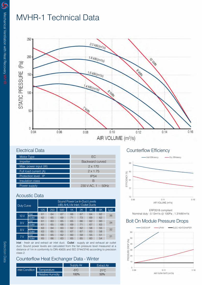
MVHR-1 Technical Data
Motor Type
Impeller
Max. power input (W)
Full load current (A)
Protection level : IP
Insulation class
Power supply
ECBackward curved
2 x 1702 x 1.75
IP54B
230 V AC, 1 ~ 50Hz
Electrical Data
Acoustic Data
Inlet - fresh air and extract air inlet duct. Outlet - supply air and exhaust air outlet duct. Sound power levels are calculated from the fan pressure level measured at a distance of 1m in conformity to DIN 45635 and ISO 3744/3745 according to precision class 2.
Duty CurveSound Power Lw In-Duct Levels (dB) AHU Air Inlet / Outlet Ducts
125 1K250 2K 8K500 4K LpA
10 VInlet
Inlet
Inlet
Inlet
Outlet
Outlet
Outlet
Outlet
9 V
8 V
7 V
61 64 67 66 67 64 62 3662 65 69 71 73 69 62 61 63 65 65 66 62 60 61 65 68 69 71 67 63 63 64 63 62 62 58 55 63 65 65 67 67 63 58 65 65 62 60 59 55 51 65 66 63 65 65 60 54
Counterflow Efficiency
Bolt On Module Pressure Drops34
32
31
Counterflow Heat Exchanger Data - Winter
Inlet Condition Temperature
Relative Humidity
Supply Air Extract Air
-5°C 21°C100% 50%
ERP2018 compliantNominal duty : 0.13m³/s @ 100Pa ; 1.31kW/m³/s

Selection D
ataM
echanical Ventilation with H
eat Recovery M
VHR
MVHR-1 Dimensions, Weight & Technical Data
Width Height Length Inlet Spigot Oulet Spigot Weight
750mm 310mm 1225mm Ø 200 mm Ø 200 mm 90 kg
Heater Model Output (kW) Power SupplyNom. Current
(A)Inlet Spigot
DimensionsW x H x L (mm)
EAHBO1/1.5 1.5 230V/1PH/50Hz 6.6 Ø 200 mm 450 x 310 x 490
Unit Dimensions
Electric Heater Battery Bolt On Module (On/Off Control)
Heater Model Output (kW) Power SupplyNom. Current
(A)Inlet Spigot
DimensionsW x H x L (mm)
EAHBT1/1.5 1.5 230V/1PH/50Hz 6.6 Ø 200 mm 450 x 310 x 490
Electric Heater Battery Bolt On Module (Thyristor Control)
Heater Model Nominal Output (kW) Outlet Spigot DimensionsW x H x L (mm)
LPHW1/1R 450 x 310 x 490
Low Pressure Hot Water Coil Bolt On Module
2.0 Ø 200 mm
Cooler Model Nominal Output (kW) Outlet Spigot DimensionsW x H x L (mm)
CW1/2R 450 x 310 x 490
Chilled Water Coil Bolt On Module
1.0 Ø 200 mm
Heater Model Output (kW) Refrigerant Condenser Inlet SpigotDimensions
W x H x L (mm)
DXHP1/2R 1.0 R410A SM564ATP-E Ø 200 mm 450 x 310 x 490
DX Heat Pump Coil Bolt On Module
*DX Cooling only is possible using the DXHP Module*

Selection D
ataM
echanical Ventilation with H
eat Recovery M
VHR
MVHR-2 Technical Data
Motor Type
Impeller
Max. power input (W)
Full load current (A)
Protection level : IP
Insulation class
Power supply
ECBackward curved
2 x 1702 x 1.65
IP54B
230 V AC, 1 ~ 50Hz
Electrical Data
Acoustic Data
Inlet - fresh air and extract air inlet duct. Outlet - supply air and exhaust air outlet duct. Sound power levels are calculated from the fan pressure level measured at a distance of 1m in conformity to DIN 45635 and ISO 3744/3745 according to precision class 2.
Duty CurveSound Power Lw In-Duct Levels (dB) AHU Air Inlet / Outlet Ducts
125 1K250 2K 8K500 4K LpA
10 VInlet
Inlet
Inlet
Inlet
Outlet
Outlet
Outlet
Outlet
9 V
8 V
7 V
64 67 63 63 63 63 59 3665 74 69 70 71 66 62 63 66 62 61 60 60 55 64 72 66 67 68 62 59 65 66 61 59 57 56 51 67 71 65 65 65 59 54 65 62 57 56 54 53 47 66 67 61 62 62 56 50
Counterflow Efficiency
Bolt On Module Pressure Drops35
34
30
Counterflow Heat Exchanger Data - Winter
Inlet Condition Temperature
Relative Humidity
Supply Air Extract Air
-5°C 21°C100% 50%
ERP2018 compliantNominal duty : 0.16m³/s @ 100Pa ; 0.891kW/m³/s

Selection D
ataM
echanical Ventilation with H
eat Recovery M
VHR
MVHR-2 Dimensions, Weight & Technical Data
Width Height Length Inlet Spigot Oulet Spigot Weight
800mm 365mm 1410mm Ø 250 mm Ø 250 mm 120 kg
Heater Model Output (kW) Power SupplyNom. Current
(A)Inlet Spigot
DimensionsW x H x L (mm)
EAHBO2/1.5 1.5 230V/1PH/50Hz 6.6 Ø 250 mm 500 x 365 x 490
Unit Dimensions
Electric Heater Battery Bolt On Module (On/Off Control)
Heater Model Output (kW) Power SupplyNom. Current
(A)Inlet Spigot
DimensionsW x H x L (mm)
EAHBT2/2.0 2.0 230V/1PH/50Hz 8.7 Ø 250 mm 500 x 365 x 490
Electric Heater Battery Bolt On Module (Thyristor Control)
Heater Model Nominal Output (kW) Outlet Spigot DimensionsW x H x L (mm)
LPHW2/1R 500 x 365 x 490
Low Pressure Hot Water Coil Bolt On Module
2.5 Ø 250 mm
Cooler Model Nominal Output (kW) Outlet Spigot DimensionsW x H x L (mm)
CW2/2R 500 x 365 x 490
Chilled Water Coil Bolt On Module
1.9 Ø 250 mm
Heater Model Output (kW) Refrigerant Condenser Inlet SpigotDimensions
W x H x L (mm)
DXHP2/2R 1.8 R410A SM564ATP-E Ø 250 mm 500 x 365 x 490
DX Heat Pump Coil Bolt On Module
*DX Cooling only is possible using the DXHP Module*

Selection D
ataM
echanical Ventilation with H
eat Recovery M
VHR
MVHR-3 Technical Data
Motor Type
Impeller
Max. power input (W)
Full load current (A)
Protection level : IP
Insulation class
Power supply
ECBackward curved
2 x 1702 x 1.75
IP54B
230 V AC, 1 ~ 50Hz
Electrical Data
Acoustic Data
Inlet - fresh air and extract air inlet duct. Outlet - supply air and exhaust air outlet duct. Sound power levels are calculated from the fan pressure level measured at a distance of 1m in conformity to DIN 45635 and ISO 3744/3745 according to precision class 2.
Duty CurveSound Power Lw In-Duct Levels (dB) AHU Air Inlet / Outlet Ducts
125 1K250 2K 8K500 4K LpA
10 VInlet
Inlet
Inlet
Inlet
Outlet
Outlet
Outlet
Outlet
9 V
8 V
7 V
64 67 64 64 62 62 56 3665 73 68 69 69 64 58 65 67 63 62 60 59 53 66 72 66 67 67 61 55 69 65 61 60 57 54 48 69 71 65 65 65 57 50 67 61 58 56 54 50 43 67 67 61 62 61 53 45
Counterflow Efficiency
Bolt On Module Pressure Drops35
34
30
Counterflow Heat Exchanger Data - Winter
Inlet Condition Temperature
Relative Humidity
Supply Air Extract Air
-5°C 21°C100% 50%
ERP2018 compliantNominal duty : 0.19m³/s @ 100Pa ; 0.47kW/m³/s

Selection D
ataM
echanical Ventilation with H
eat Recovery M
VHR
MVHR-3 Dimensions, Weight & Technical Data
Width Height Length Inlet Spigot Oulet Spigot Weight
1375mm 400mm 1535mm Ø 315 mm Ø 315 mm 215 kg
Heater Model Output (kW) Power SupplyNom. Current
(A)Inlet Spigot
DimensionsW x H x L (mm)
EAHBO3/2.0 2.0 230V/1PH/50Hz 8.7 Ø 315 mm 585 x 400 x 490
Unit Dimensions
Electric Heater Battery Bolt On Module (On/Off Control)
Heater Model Output (kW) Power SupplyNom. Current
(A)Inlet Spigot
DimensionsW x H x L (mm)
EAHBT3/2.5 2.5 230V/1PH/50Hz 10.9 Ø 315 mm 585 x 400 x 490
Electric Heater Battery Bolt On Module (Thyristor Control)
Heater Model Nominal Output (kW) Outlet Spigot DimensionsW x H x L (mm)
LPHW3/1R 585 x 400 x 490
Low Pressure Hot Water Coil Bolt On Module
3.5 Ø 315 mm
Cooler Model Nominal Output (kW) Outlet Spigot DimensionsW x H x L (mm)
CW3/2R 585 x 400 x 490
Chilled Water Coil Bolt On Module
2.0 Ø 315 mm
Heater Model Output (kW) Refrigerant Condenser Inlet SpigotDimensions
W x H x L (mm)
DXHP3/2R 2.5 R410A SM564ATP-E Ø 315 mm 585 x 400 x 490
DX Heat Pump Coil Bolt On Module
*DX Cooling only is possible using the DXHP Module*

Selection D
ataM
echanical Ventilation with H
eat Recovery M
VHR
MVHR-4 Technical Data
Motor Type
Impeller
Max. power input (W)
Full load current (A)
Protection level : IP
Insulation class
Power supply
ECBackward curved
2 x 5002 x 2.20
IP54B
230 V AC, 1 ~ 50Hz
Electrical Data
Acoustic Data
Inlet - fresh air and extract air inlet duct. Outlet - supply air and exhaust air outlet duct. Sound power levels are calculated from the fan pressure level measured at a distance of 1m in conformity to DIN 45635 and ISO 3744/3745 according to precision class 2.
Duty CurveSound Power Lw In-Duct Levels (dB) AHU Air Inlet / Outlet Ducts
125 1K250 2K 8K500 4K LpA
10 VInlet
Inlet
Inlet
Inlet
Outlet
Outlet
Outlet
Outlet
9 V
8 V
7 V
72 73 76 76 75 71 69 4576 78 81 81 80 76 74 69 72 74 74 73 69 66 74 77 79 79 78 74 71 67 70 70 70 68 65 61 72 75 75 75 74 70 66 66 67 67 67 65 61 56 71 72 72 72 70 66 61
Counterflow Efficiency
Bolt On Module Pressure Drops44
40
37
Counterflow Heat Exchanger Data - Winter
Inlet Condition Temperature
Relative Humidity
Supply Air Extract Air
-5°C 21°C100% 50%
ERP2018 compliantNominal duty : 0.39m³/s @ 100Pa ; 0.94kW/m³/s

Selection D
ataM
echanical Ventilation with H
eat Recovery M
VHR
MVHR-4 Dimensions, Weight & Technical Data
Width Height Length Inlet Spigot Oulet Spigot Weight
1375mm 400mm 1535mm Ø 315 mm Ø 315 mm 215 kg
Heater Model Output (kW) Power SupplyNom. Current
(A)Inlet Spigot
DimensionsW x H x L (mm)
EAHBO4/3.0 3.0 230V/1PH/50Hz 13.0 Ø 315 mm 585 x 400 x 490
Unit Dimensions
Electric Heater Battery Bolt On Module (On/Off Control)
Heater Model Output (kW) Power SupplyNom. Current
(A)Inlet Spigot
DimensionsW x H x L (mm)
EAHBT4/3.5 3.5 230V/1PH/50Hz 15.2 Ø 315 mm 585 x 400 x 490
Electric Heater Battery Bolt On Module (Thyristor Control)
Heater Model Nominal Output (kW) Outlet Spigot DimensionsW x H x L (mm)
LPHW4/1R 585 x 400 x 490
Low Pressure Hot Water Coil Bolt On Module
3.5 Ø 315 mm
Cooler Model Nominal Output (kW) Outlet Spigot DimensionsW x H x L (mm)
CW4/2R 585 x 400 x 490
Chilled Water Coil Bolt On Module
2.0 Ø 315 mm
Heater Model Output (kW) Refrigerant Condenser Inlet SpigotDimensions
W x H x L (mm)
DXHP4/2R 3.0 R410A SM564ATP-E Ø 315 mm 585 x 400 x 490
DX Heat Pump Coil Bolt On Module
*DX Cooling only is possible using the DXHP Module*

Selection D
ataM
echanical Ventilation with H
eat Recovery M
VHR
MVHR-5 Technical Data
Motor Type
Impeller
Max. power input (W)
Full load current (A)
Protection level : IP
Insulation class
Power supply
ECBackward curved
2 x 5002 x 2.20
IP54B
230 V AC, 1 ~ 50Hz
Electrical Data
Acoustic Data
Inlet - fresh air and extract air inlet duct. Outlet - supply air and exhaust air outlet duct. Sound power levels are calculated from the fan pressure level measured at a distance of 1m in conformity to DIN 45635 and ISO 3744/3745 according to precision class 2.
Duty CurveSound Power Lw In-Duct Levels (dB) AHU Air Inlet / Outlet Ducts
125 1K250 2K 8K500 4K LpA
10 VInlet
Inlet
Inlet
Inlet
Outlet
Outlet
Outlet
Outlet
9 V
8 V
7 V
72 74 72 70 67 67 64 4277 79 77 75 72 72 69 71 72 71 68 66 65 61 76 77 76 73 71 70 66 69 69 68 65 62 60 55 74 74 73 70 67 65 60 66 66 65 62 59 57 51 71 71 70 67 64 62 56
Counterflow Efficiency
Bolt On Module Pressure Drops41
38
35
Counterflow Heat Exchanger Data - Winter
Inlet Condition Temperature
Relative Humidity
Supply Air Extract Air
-5°C 21°C100% 50%
ERP2018 compliantNominal duty : 0.55m³/s @ 100Pa ; 0.654kW/m³/s

Selection D
ataM
echanical Ventilation with H
eat Recovery M
VHR
MVHR-5 Dimensions, Weight & Technical Data
Width Height Length Inlet Spigot Oulet Spigot Weight
1635mm 480mm 1950mm Ø 400 mm Ø 400 mm 305 kg
Heater Model Output (kW) Power SupplyNom. Current
(A)Inlet Spigot
DimensionsW x H x L (mm)
EAHBO5/5.0 5.0 230V/1PH/50Hz 21.7 Ø 400 mm 585 x 480 x 490
Unit Dimensions
Electric Heater Battery Bolt On Module (On/Off Control)
Heater Model Output (kW) Power SupplyNom. Current
(A)Inlet Spigot
DimensionsW x H x L (mm)
EAHBT5/6.0 6.0 230V/1PH/50Hz 26.0 Ø 400 mm 585 x 480 x 490
Electric Heater Battery Bolt On Module (Thyristor Control)
Heater Model Nominal Output (kW) Outlet Spigot DimensionsW x H x L (mm)
LPHW5/1R 585 x 480 x 490
Low Pressure Hot Water Coil Bolt On Module
6.5 Ø 400 mm
Cooler Model Nominal Output (kW) Outlet Spigot DimensionsW x H x L (mm)
CW5/2R 585 x 480 x 490
Chilled Water Coil Bolt On Module
3.0 Ø 400 mm
Heater Model Output (kW) Refrigerant Condenser Inlet SpigotDimensions
W x H x L (mm)
DXHP5/2R 3.5 R410A SM804ATP-E Ø 400 mm 585 x 480 x 490
DX Heat Pump Coil Bolt On Module
*DX Cooling only is possible using the DXHP Module*

Selection D
ataM
echanical Ventilation with H
eat Recovery M
VHR
MVHR-6 Technical Data
Motor Type
Impeller
Max. power input (W)
Full load current (A)
Protection level : IP
Insulation class
Power supply
ECBackward curved
2 x 10002 x 1.63
IP54B
400 V AC, 3 ~ 50Hz
Electrical Data
Acoustic Data
Inlet - fresh air and extract air inlet duct. Outlet - supply air and exhaust air outlet duct. Sound power levels are calculated from the fan pressure level measured at a distance of 1m in conformity to DIN 45635 and ISO 3744/3745 according to precision class 2.
Duty CurveSound Power Lw In-Duct Levels (dB) AHU Air Inlet / Outlet Ducts
125 1K250 2K 8K500 4K LpA
10 VInlet
Inlet
Inlet
Inlet
Outlet
Outlet
Outlet
Outlet
9 V
8 V
7 V
66 75 74 71 73 71 69 4267 74 76 80 80 77 74 64 74 72 69 71 70 67 66 72 75 79 78 75 71 64 69 69 67 69 67 62 65 71 72 77 75 72 67 63 66 66 64 66 63 58 65 68 69 74 72 70 63
Counterflow Efficiency
Bolt On Module Pressure Drops41
38
35
Counterflow Heat Exchanger Data - Winter
Inlet Condition Temperature
Relative Humidity
Supply Air Extract Air-5°C 21°C
100% 50%
ERP2018 compliantNominal duty : 0.90m³/s @ 100Pa ; 1.153kW/m³/s

Selection D
ataM
echanical Ventilation with H
eat Recovery M
VHR
MVHR-6 Dimensions, Weight & Technical Data
Width Height Length Inlet Spigot Oulet Spigot Weight
1665mm 715mm 2155mm 400 kg
Heater Model Output (kW) Power SupplyNom. Current
(A)Inlet Spigot
DimensionsW x H x L (mm)
EAHBO6/9.0 9.0 230V/1PH/50Hz 39.1 720 x 615 x 490
Unit Dimensions
Electric Heater Battery Bolt On Module (On/Off Control)
Heater Model Output (kW) Power SupplyNom. Current
(A)Inlet Spigot
DimensionsW x H x L (mm)
EAHBT6/9.0 9.0 230V/1PH/50Hz 39.1 720 x 615 x 490
Electric Heater Battery Bolt On Module (Thyristor Control)
Heater Model Nominal Output (kW) Outlet Spigot DimensionsW x H x L (mm)
LPHW6/1R 720 x 615 x 490
Low Pressure Hot Water Coil Bolt On Module
10.0
Cooler Model Nominal Output (kW) Outlet Spigot DimensionsW x H x L (mm)
CW6/2R 720 x 615 x 490
Chilled Water Coil Bolt On Module
4.5
Heater Model Output (kW) Refrigerant Condenser Inlet SpigotDimensions
W x H x L (mm)
DXHP6/2R 4.5 R410A SM804ATP-E 720 x 615 x 490
DX Heat Pump Coil Bolt On Module
*DX Cooling only is possible using the DXHP Module*
600 x 565 mm
600 x 565 mm
600 x 565 mm
600 x 565 mm
600 x 565 mm750 x 565 mm
750 x 565 mm

Selection D
ataM
echanical Ventilation with H
eat Recovery M
VHR
Duct Silencers
All silencers are matched to MVHR connection sizes. Circular silencers have minimal pressure drop due to being straight through type. MVHR-6
uses rectangular silencers and therefore has a pressure profile as below curve:
OUTER Ø
DETAILSINSERTION LOSSES (dB)
Attenuator Insertion Losses
125 Hz 250 Hz 1000 Hz500 Hz WEIGHT2000 Hz 4000 Hz 8000 Hz
3
4
4
2
3
4
2
2
3
2
2
3
2
2
2
7
7
10
10
12
12
7
10
12
5
7
9
4
6
8
4
6
8
4
5
6
14
14
18
18
22
22
14
20
25
12
17
23
11
15
19
11
15
19
9
12
16
22
22
29
29
36
36
29
38
47
27
36
45
22
30
38
22
30
38
15
19
24
17
17
23
23
30
30
21
27
33
17
21
26
13
16
18
13
16
18
7
9
10
13
13
16
16
20
20
16
19
22
13
15
18
11
13
15
11
13
15
7
9
10
10
10
12
12
13
13
15
18
21
13
15
17
10
12
14
10
12
14
6
7
9
7
7
8
8
9
9
MVHR-1 - 200Ø - 615 Long
MVHR-1 - 200Ø - 915 Long
MVHR-1 - 200Ø - 1215 Long
MVHR-2 - 250Ø - 615 Long
MVHR-2 - 250Ø - 915 Long
MVHR-2 - 250Ø - 1215 Long
MVHR-3 - 315Ø - 615 Long
MVHR-3 - 315Ø - 915 Long
MVHR-3 - 315Ø - 1215 Long
MVHR-4 - 315Ø - 615 Long
MVHR-4 - 315Ø - 915 Long
MVHR-4 - 315Ø - 1215 Long
MVHR-5 - 400Ø - 615 Long
MVHR-5 - 400Ø - 915 Long
MVHR-5 - 400Ø - 1215 Long
MVHR-6 - 600 x 565 x 650 Long
MVHR-6 - 750 x 565 x 650 Long
MVHR-6 - 600 x 565 x 950 Long
MVHR-6 - 750 x 565 x 950 Long
MVHR-6 - 600 x 565 x 1250 Long
MVHR-6 - 750 x 565 x 1250 Long
310
360
425
425
N/A
510
8
12
15
10
14
18
12
17
21
12
17
21
14
20
26
32
38
43
51
54
65
MODEL
OUTERØ
LENGTH
LENGTHWIDTH
HEI
GH
T

Selection D
ataM
echanical Ventilation with H
eat Recovery M
VHR
External MVHR Dimensions
306
358
393
393
478
715
250
300
365
365
450
500
85
115
120
120
125
130
1175
1357
1487
1487
1892
2105
750
795
1375
1375
1630
1665
1545
1777
1972
1972
2462
2725
790
835
1415
1415
1670
1705
750
795
1375
1375
1630
1665
1225
1407
1537
1537
1972
2155
491
573
613
613
703
945
100
155
310
310
400
580
MVHR-1MVHR-2MVHR-3MVHR-4MVHR-5MVHR-6
Unit Length
Unit Width
Unit Height
CowlLength
Roof Height
Base Length
Base Width
Total Length
Total Width
Total Height
Weightkg
MODEL
ECE-MVHR Drain TrapBuilt-in ball valve effectively traps the drainage system in the absence of condensate. It is easy to install and maintain. When connecting socket with
pipe work, socket should be moistened with water and soap. Each ECE-MVHR condensate drain system should be provided with a separate siphon.
Casing Constructed to the following classes in accordance with BS EN1886:2007:
• Used by many European major manufacturers
• The size is very compact no additional height required
• It works in both -ve and +ve pressure conditions
• Suitable for most HVAC pressures – customer dry pressure tests up to 1500Pa +ve / -ve
• Available in Grey or Clear plastic
• Connection size 32 mm OD – 2x transformation to 40mm available as extra
• Supplied with sealing cap inner sealing ring, fixing bracket and heater cable screws / retainer
• It is possible to add a heater at 230 V or 24 V to avoid freezing
• Please note: Not included as standard and can be supplied loose for fitting by others at an additional cost.

ECE UK Ltd.
T
E
W
A
+44 (0)1634729690
www.eceuk.com
Pharaoh House, Arnolde
Close, Rochester, Kent,
ME2 4QW
AAHanything air handling
© 2019 ECE UK Ltd.
Did you know...?
• Our MVHR’s contain Counter-flow heat exchangers with summer bypass offering up
to 95% efficiency.
• Highly efficient EC Fans offering great energy saving solutions.
• Low specific fan power helps to achieve Part L2 building compliance.
• All MVHR units come complete with F7 supply and M5 return panel filters as
standard.
• Low height offering space saving solutions, starting from 310mm high.
• The ECE-Tech controller is fully expandable to suit your project requirements, up to
2060 Digital I/O and 511 Analogue I/O ports.
• The controller facilitates the use of BACnet and Modbus.
• External Units not available with bottom or top access.
• Dampers need to be selected if using LPHW or CHW coils.
• Dampers come complete with spring return actuators.
• Where controls are fitted, filter pressure switches and bypass actuators are
included.
• Cooling only available up to 2.5m/s coil velocity, so the MVHR may require
oversizing to use a cooling bolt on. Eliminators fitted as standard.
• ECE offers a large variety of stock items that enable you to keep your unit, running
throughout its lifetime. Single click Basket for consumables with Anything Air
Handling, our Spares & Parts shop www.aahuk.com
• We also offer a bespoke design option for any projects that might not currently fit
into our standard range of products.