mechanical testing of steam generator support bolts
TRANSCRIPT

9
810910 8201200608 0 305 PDR ADOCK PDR P
TECHNICAL REPORT TR-5160-1
MECHANICAL TESTING OF STEAM GENERATOR SUPPORT BOLTS
AUGUST 11, 1981
SoTELEDYNE ENGINEERING SERVICES
303 BEAR HILL ROAD 'AIALTHAM, MASSACHUSETTS 02154
617-890-3350

AweTELEDYNE
Technical Report ENGINEERING SERVICES TR-5160-1 -1
Teledyne Engineering Services (TES) has, at the request of Wisconsin
Public Service Company (WPSC) performed tensile, impact, and hardness
tests on two steam generator support bolts. This report presents the
results of this testing.
WPSC supplied TES with two bolts from steam generator supports from
their Kewaunee plant. The bolts are made of a material identified as
Vascomax 250 CVM, a high strength maraging steel supplied by Teledyne
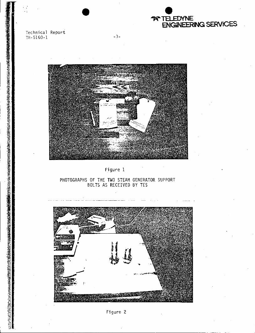
Vasco. Both bolts are shown in Figures 1 and 2. The threads on the longer
bolt were stripped during removal of the bolt from the steam generator in
the plant. The bolts had been installed with Heli-Coils.
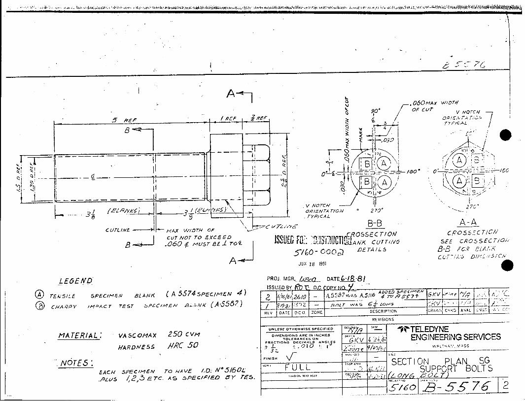
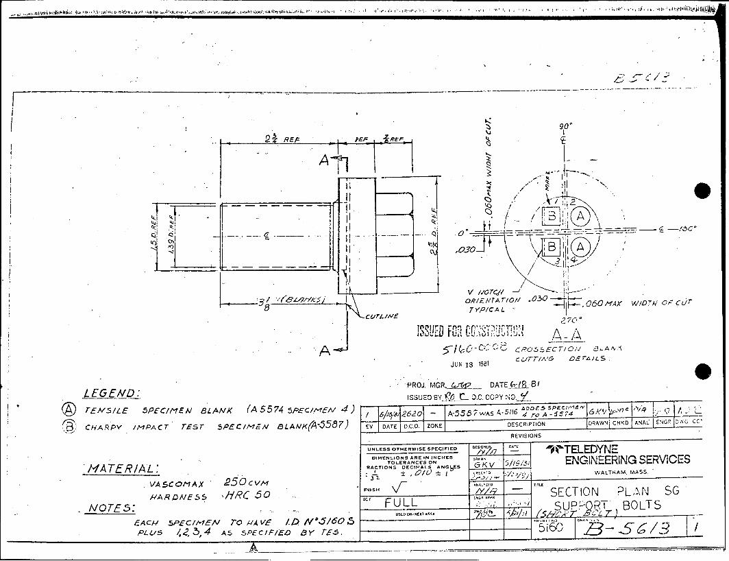
The bolts were sectioned as shown by the drawings in Attachment 1 to
provide four full size charpy and four sub-size tensile specimens from the
long bolt, and two full size charpy, and two sub-size tensile specimens
from the short bolt. Also in Attachment 1 are the detail drawings for the
specimens.
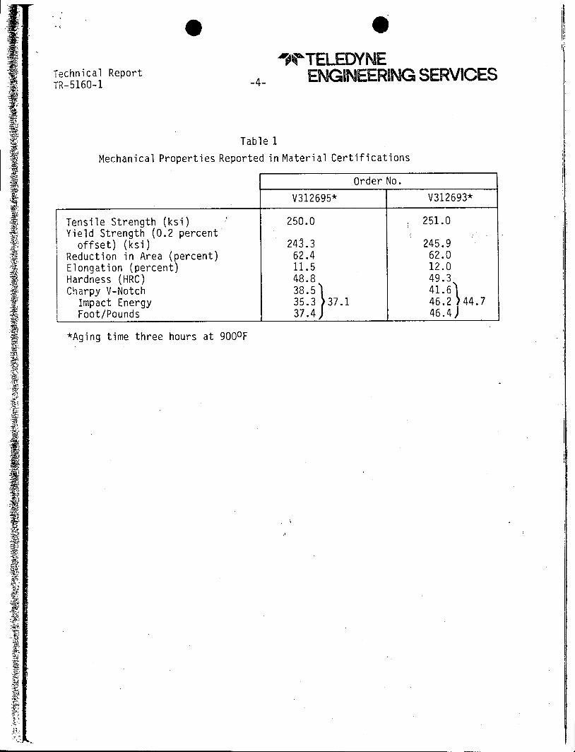
These bolts were parts of original installation and had been tested
previously as a part of material certification. These results are shown in
Table 1.
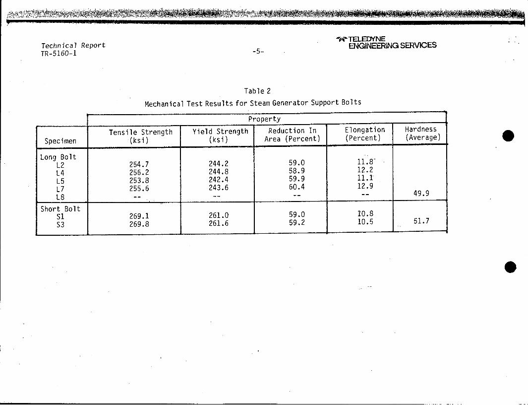
The results of TES's tests are shown in Tables 2 and 3. In Table 4,
the TES results are presented along with values previously reported in the
material certification, and results expected based on Teledyne Vasco's
literature. There are two columns for the Teledyne Vasco literature: the
first column is from literature approximately from the period when the
bolts were obtained, the second the most recent Teledyne Vasco literature
on the same material. Copies of TES test reports are included as Attach
ment 2, and copies of the relevant sections of the Teledyne Vasco litera
ture are in Attachment 3.
K.TELEDYNE Technical Report ENGINEERING SERVICES TR-5160-1 -2
The results obtained by TES are in agreement with values reported in
the Teledyne Vasco literature. The results are also in agreement with the
material certifications except TES found lower charpy impact values.
The original material certification charpy tests and TES's confirma
tion charpy tests were performed at 400F. At the request of WPSC, one charpy test was performed at 700F. The result at 70oF was consistant with the 400F tests as expected from the Teledyne Vasco literature which shows
the charpy impact energy-temperature curve to be flat at these temperatures.
TES considered the environment in which these bolts were placed, and
the metallurgy of this material. We can find no factor that could cause a reduction in the charpy impact values. Since the TES results are in agreement with the Teledyne Vasco literature, it is our opinion that the
original material certification charpy results are questionable. It is also our opinion that there has been no deterioration in the mechanical properties of these bolts.
Technical Report TR-5160-1 -3-
Figure 1
PHOTOGRAPHS OF THE TWO STEAM GENERATOR SUPPORT BOLTS AS RECEIVED BY TES
Figure 2
0 WTEL.EDYNE
EraEERNGSERVICES
Technical Report TR-5160-1 -4-
'WNTELEDYNE ENGINEERING SERVICES
Table 1
Mechanical Properties Reported in Material Certifications
Order No.V312695* V312693*
Tensile Strength (ksi) 250.0 251.0 Yield Strength (0.2 percent'
offset) (ksi) 24.3 245.9 Reduction in Area (percent) 62.4 62.0 Elongation (percent) 11.5 12.0 Hardness (HRC) 48.8 49.3 Charpy V-Notch 38.5 41.6
Impact Energy 35.3 37.1 46.2 44.7 Foot/Pounds 37.4 46.4
*Aging time three hours at 9000 F
Technical Report TR-5160-1 -5-
-oTELEINNE ENGINEERING SERVICES
Table 2
Mechanical Test Results for Steam Generator Support Bolts
Property
Tensile Strength Yield Strength Reduction In Elongation Hardness
Specimen (ksi) (ksi) Area (Percent) (Percent) (Average)
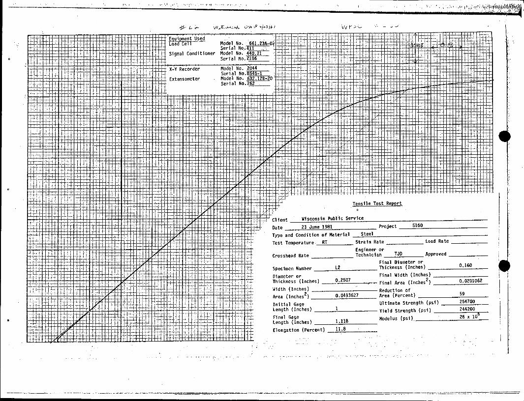
Long Bolt L2 254.7 244.2 59.0 11.8
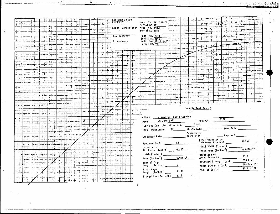
L4 256.2 244.8 58.9 12.2
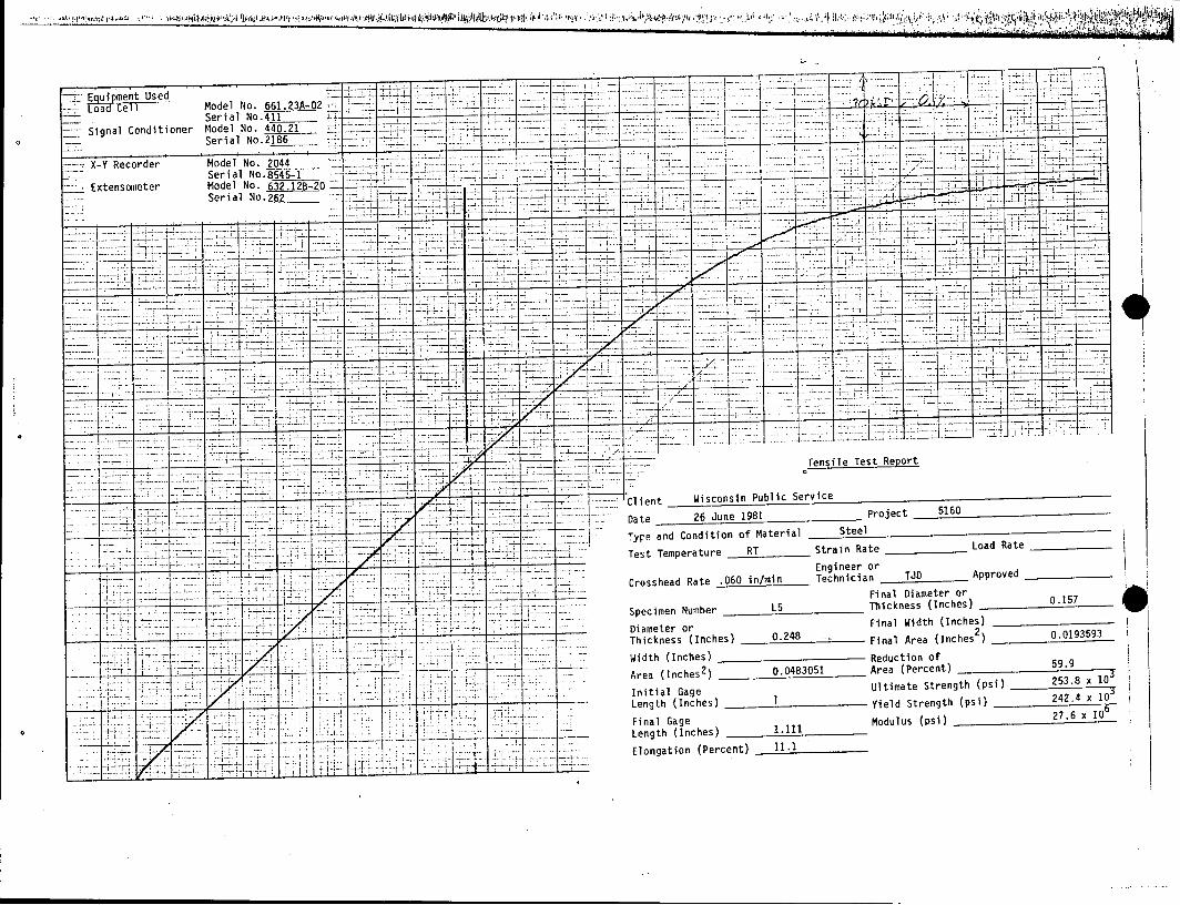
L5 253.8 242.4 59.9 11.1
L7 255.6 243.6 60.4 12.9
L8 -- -- -- 49.9
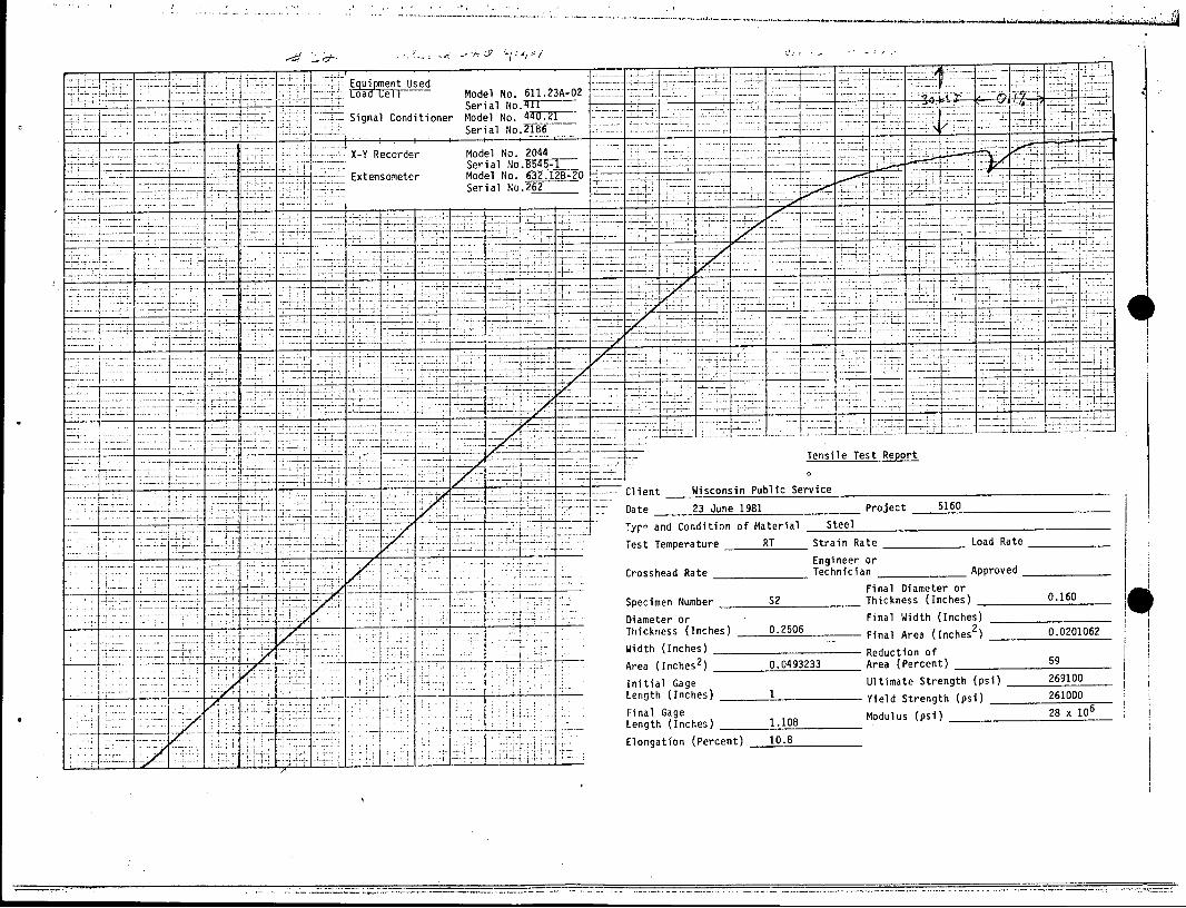
Short Bolt S1 269.1 261.0 59.0 10.8
S3 269.8 261.6 59.2 10.5 51.7
WOW T
Technical Report TR-5160-1 -6-
S0 TELEDYNE ENGINEERING SERVICES
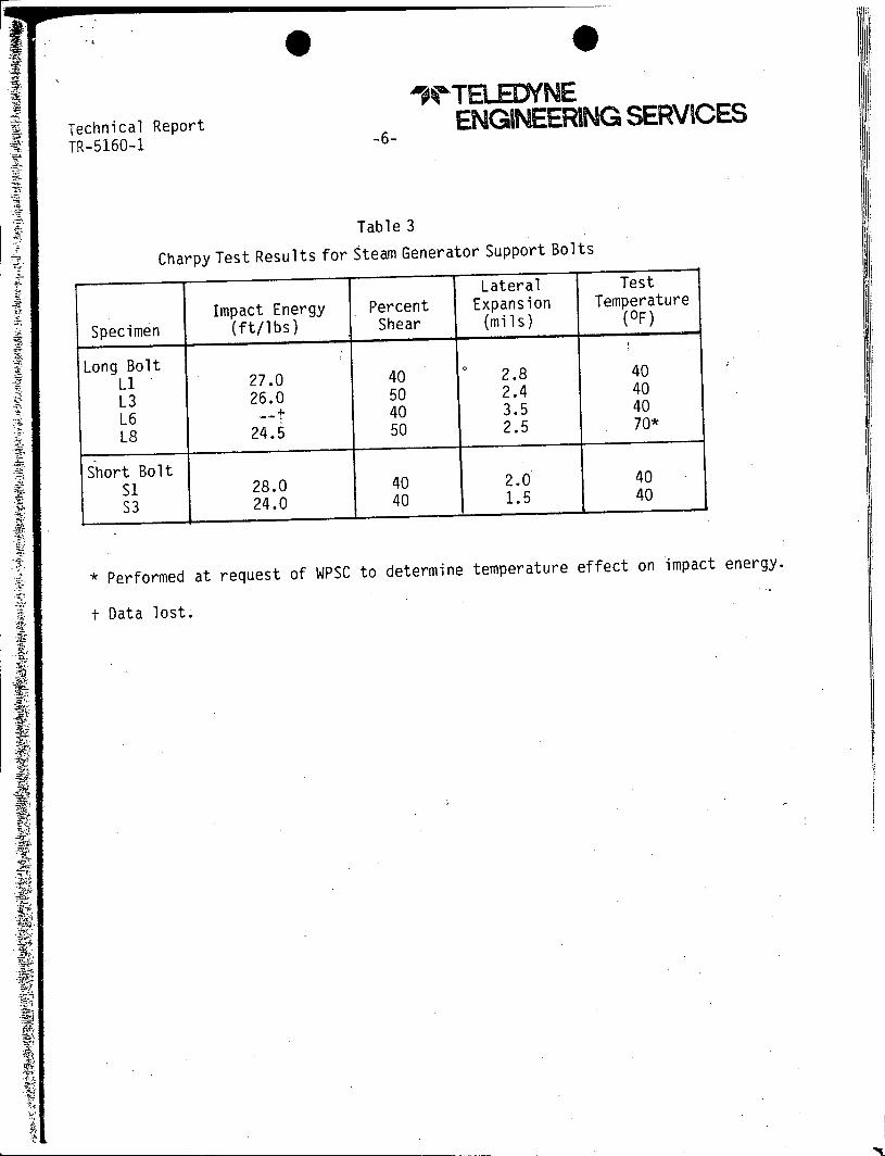
Table 3
Charpy Test Results for Steam Generator Support Bolts
* Performed at request of WPSC to determine temperature effect on impact energy.
t Data lost.
Technical Report TR-5160-1
Comparison of
-7-
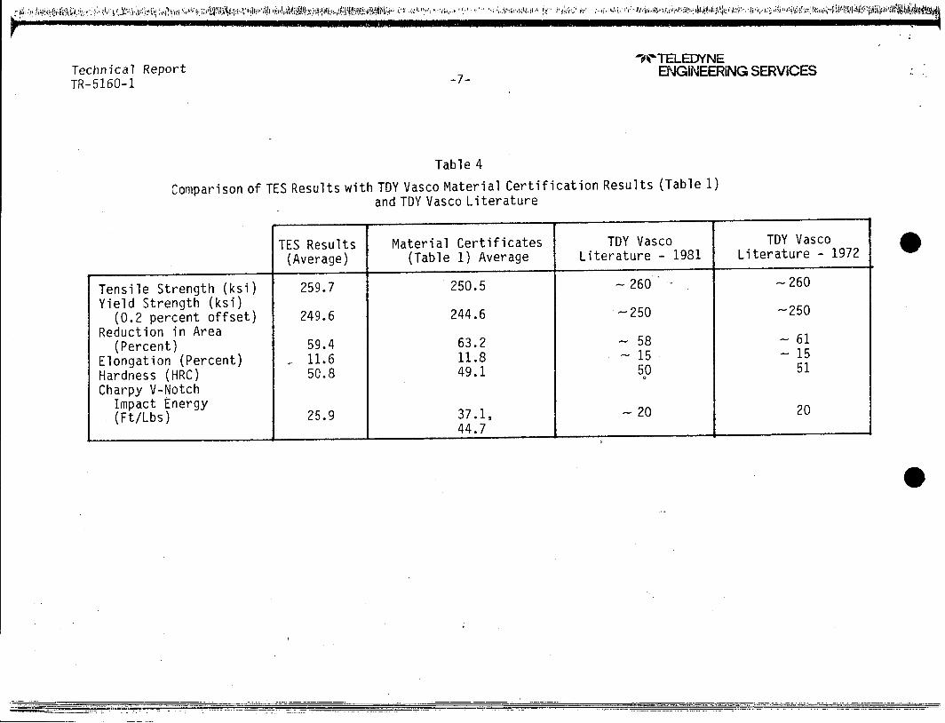
Table 4
TES Results with TDY Vasco Material Certification Results (Table 1) and TDY Vasco Literature
V I I
TES Results (Average)
Material Certificates (Table 1) Average
TDY Vasco Literature - 1981
TDY Vasco Literature - 1972
Tensile Strength (ksi) 259.7 250.5 260 - -260
Yield Strength (ksi) (0.2 percent offset) 249.6 244.6 -250 -250
Reduction in Area (Percent) 59.4 63.2 - 58 - 61
Elongation (Percent) 11.6 11.8 15 - 15
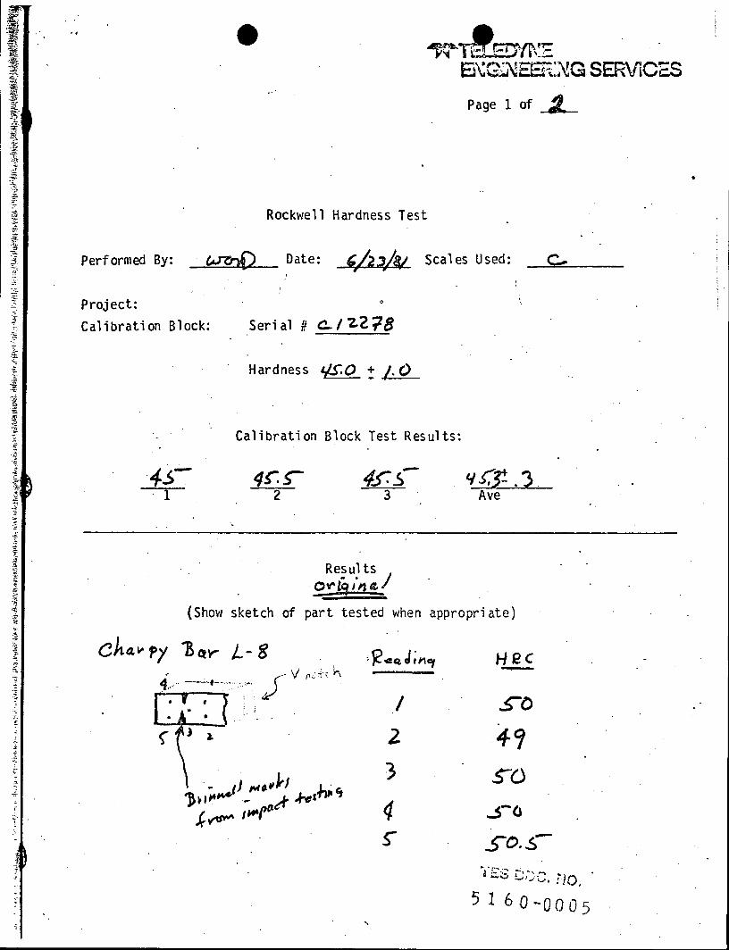
Hardness (HRC) 50.8 49.1 50 51
Charpy V-Notch Impact Energy 20 (Ft/Lbs) 25.9 37.1, - 20
44.7
SNTEL.EDYNE ENGINEERING SERVICES
tj: ).y 1,.; , ,O 1, ;. A) :e
0 9 Wt TELEDYNE
ENGINEERING SERVICES
ATTACHMENT 1
.c~: §77(___
CUTL/N--E MAX VWDT4 OF
CUTNOT TO c XCEc o,0
.060 1-us r aE I o
A-q
\ K'-ec
JV go*
11 00h
ORIENTA r/ON o 270' TYPICAL
17Z/ B-B
ISSUMf F0._: .'24"'MIJM ASKCCUTT7/V G
-- ,r/ A- r^! rnt n 1 DE TA/IL5
JUN 18 1981
OF CUTWIDTH
V NQCH
TYPICAL -7 * -. a
2 70'
A-A
CRO SScC T/C. SECRS
L E6E /D
STEA//.E SPEC/MEV BLANK (A 5574 5PEC/mEv 4)
C/RAPPY IMcACT TEST 5pEC/4.6vN LA/v< (A-5567)
MA TERIA L : VA SC OMAX 250 cvm
HARDNESS //RC 50
NOTE5:EACH SPE-cMC/EN To AAVE 1.D. .5/60L. J0 LUS ,2,ETC. AS 5PEC/-/ED fY TeS.
PROJ. MGRAnrq_ DATE64 8 / ISSUEDlR BY r' DC (f0PY NA
61 /L5587wAS.A5116 fomeo ,.,,9 t
/ ,', 2m -STen WAS s5-zLOA'G REV DATE .C.O. ZONE DESCRIPTION GRM CH-O ANAL
REVISIONS
UNLESf OTHERWISE SPECIFIED DE "- TELEDYNE DIMENSIONS ARE IN INCHES
TOLERANCES ON GV ; ENGINEERING SERVICES FRACTIONS DECIMALS ANGL S
- 1- ,t 010 A' w 7. M s 3 Z.-----7K_!
FINISH \/ SECT I ON PLAN SG ^ U L L SUPPORT BOLT S
,moosarmes,0 Z_/ fh T) ISSUED- -Y 0_rDrIoDv NQ 55q
3'~B~-55762
i
A-*-]
£ f>C/Y
2z REF F~F ZRAP'Si
'4.
0 1,0
0
5,'
0/
V //O74/-' OR/IENTATIrO/ .6rx-3 -
TYPICAL j..--.06O/Ax WIL)TA/ cL/r
2 70 '
) FU CO 812 J A- A p'f(,C' 0CRO,55ECT/CN S 4 A",.
JUN 8 1981 c trIT/AG DEA/LS
L EG END: TENS/LE 5PEC/tM-EN 8LANK (A 5574 SPEC/t4Ev 4)
CHARPY IMPACT TEST 5PEC/MEIN BLAWvK(A-5587)
MA TER/AL: VASCOMAX
ARDNMES 5 ,/HRC 50- NOTE5
,EAC' SPEC/EIN TO A V/AVE D /v.5/605 P4us 2, 4 AS SPEC/F/ED BY' TEqS.
PROJ. MGR.J4 _ DATE&/ 1 t
ISSUED BY O C. D.C. COPY N0.
/ 6//6/d260c - A-5587WA5 A-5 /f6 4o Ak' e '/A
EV DATE DC.O . ZONE DESCRIPTION DRAWN CHKD ANAL ENGR >DG CC
REVISIONS
UNLESS OTHERWISE SPECIFIED DE1=7 0 AF B
DIMENLIONS ARE IN INCHES 5 TOLERANCES ON -7 Il v 5// P ENINEEIRIING SERVICES
RACTIONS DECIMALS ANG S c V I 6/() - I a WALTHAM. MASS
Fq'H -- - SECTION PL AN SG FQ BOLTS
5160 B- 5/3
.,.,,t,,en2s'h4L~ fls'I-. I:~~#i~~tCL, J!A4,S.~vtA ttII~I .~.I.Az,.,.., ~ ~ nk$a .4,jcI.Cn~I*.,IuI sgU,4~.I's: ~'. j. ~ .1.. .~. V .It'.z' I I, 'F,' ~ t;' 'i'S Id" . 11I. Ii. NIII I , ~b IAdsMi~4~JI

_______ I - * - ~ - p p
o7 772 -" /Vc &// 2DMN// f
97E2 496?JE/G77.2 "70 carr 10 7;7 97 DA119111 ^_ 2 E'2,9 A §7/) Of 277E 6 966 L'.EA67//
C/Y/27/2 OF 27VEJ A295& .Z ^V627/ . -A
-7
'O,4Q~/'/,W 1) Z&, 9AE752E 7719 /5
6A9GE~ Z&//67 /
OO/ 7/-1-
/ / - -KG ~
-I//3 _LJ-
I-- 73'2 (fK.<ij
1~
. 0 -1L ./602-L _
-) -900i . 25 -A /' . /o r
43 '.000 - :) ' // /~q
2-00 .- o.& -'
~ 30 I ___
- A ~ ~2"i'
,n
tv 0 r1 1 d0 0 0 o z z
o a)
REV' I DATE I D.C.O. I ZONE I DESCRIPTION I - ~ ~DRAWN CHKD I ANAL t.NGR IuvI,. L.OUN
REVISIONS
UNLESS OTHERWISE SPECIFIED DL-7 DAT . TELEDYNE DIMENSIONS ARE IN INCHES ERAWNNG
TOLERANCES ON v FRACTIONS DECIMALS ANGLES
050 I /t o . WALTHAM, MASS.
FINIS I ANALY7LD TITLE
SCALE ENGR APFR
USEc ON NIxr A1,ssc REV'o I D T I DC.O I ZONEIIv
- ~ - -.
~7f-F /- -
-- I
5.5- /; lo
'I, , ' , . , " " 1 . - ! . , .' "r j" , i ", JJ4 " . k 4 ! ' U;1 I . ' ') . I , .1 .1 1, '- . I - , .. "' ', '! . , 11
2
'~2, 450
z +o. Goo
440.1
O/O,0R.J; 00/
5' 00/i
+ 03.
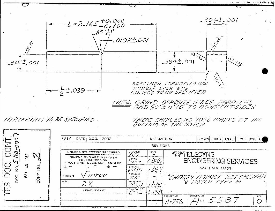
11'2/Q97&?//1 -Z 7V23d
5 A5 EC / M EN J DEA /7/wFr/ Cr / T/ O1 V /PEC/UNBER E/D 5E /F
/"o. /Y o 7C)/d &C/J/&Q
/v67~1' & ,4'/A/5) ()/C~/D ~~7 ~ /Z2 /~/Q 7j 65% /9/YZ) ~9O ~' 0 O/0~ 7/3
77/6I5;1111/,42 Z7 -/Yo TOO,/z~'677&/9 OF77/ / cL
1 REV DATE D.C.O. ZONE DESCRIPTION JDRAWNf CHKD ANAL ENGR DWGC
REVISIONS
UNLESS OTHERWISE SPECIFIED
DIMENSIONS ARE IN INCHES TOLERANCES ON
FRACTIONS OLCIMALS ANGLES
FINISH
SCALE
USED ON/NEXT ASSY
5PTELEDYNE ENGINEERIG SERVICES
WALTHAM, MASS.
-
-
Is I5587
06)1
o .
~cj Y*) *0
03
c;
0 C-,
-,7
V-WIWAIA
I
W0TELEDYNE ENGINEERING SERVICES
ATTACHMENT 2
TES TEST RESULTS
BYGNEER:NG SERVICES Page 1 of
Rockwell Hardness Test
Performed By: -w:0--- )Date: Scales Used:
Project:
Calibration Block:
1
Serial # C-/7-27?
Hardness tLy Q + ,
Calibration Block Test Results:
2 3
Results
(Show sketch of part tested when appropriate)
c~aov p ABQr 8
4-eZ~' cj
I'ow 1 ..5-0
5 1 60-0005
C-
Ave
/
2
H2C
S 0
3
4
I
e C4 JIM C,

p.-
Page 2 of ?
Rockwell Hardness Test Results
0Lbc-c~- 4- ;q,~
I
4 a rd8te s
s-Lu
a 3
9o-
FyF
4,,.,
. I
, j ---.1

A
I -s
4
I 4
Charpy Impact Test Results
Date: /9 V7/Pj Pf
Client:
Tested by:
2 0r
, b!/ LZ) Wsd
Specimen Identification
OF
Temperature Ene
Reviewed by/Accepted by: 4
Impact rgy ft-lbs
% Lateral Shear Expansion Notes
I1
TEP-3-004
A 7.o l
2. S3 4+.0O _40_,
3. L£8 __*_Z ____ __o z_
5. L 3 42__-6 z_4
6. 40o a 28.0
7.
8.
9.
10.
STTE1 YNE \ EERIG SERVICES
411 aw/ r^
_________________________________V r IIi 1i
Client wisconsin ruouli atrvoL=
Date 23 June 1981 Project 5160
Type and Condition of Material Steel
Test Temperature. RT Strain Rate _ Load Rate
Engineer or Crosshead Rate Technician TJD Approved
Final Diameter or Specimen Number L2 Thickness (Inches) 0.160
Diameter or Final Width (Inches)
Thickness (Inches) 0.2507 . Final Area (Inches2 0.0201062
Width (Inches) Reduction of Area (Inches ) 0.0493627 Area (Percent) 59
Initial Gage Ultimate Strength (psi) 254700
Length (Inches) 1 Yield Strength (psi) 244200
Final Gage Modulus (Psi) 26 x 10 Length (Inches) 1.118
Elongation (Percent) 11.8
-- ~ -- ~ - - -i:- -I
i i -- i.1 I 'I -j - - ~ ---
~bii K:
TtT'{71
--7K: 1I ~-i1 ii.
I-iL--iLYK17.
Equipment Use r - a
Signal Conditioner
- X-Y Recorder Mocel rio. ~Uqq AXY Recorder
7Extensometer
4-~
7Ih 7iIJ 4±1
7IfLV4A~ -~
~ tL~ r24+
-- I
_______ , -~--------- r - 7 - r ~
Model No. 661.23A-02 Serial No.411 Model No. 440.21 Serial No.2186
Model No. ZU44 Serial No.8545-1 Model No. 632.121-20 Serial No.262
--1<r-~I-I~V7 T
"U-
2~1~
4- c- 4-- F - { - + ~ f
.11 ~Kiii________
LL'l
:1. IL
~~.1
- ± ~.- L -4- 4-~- + - + -v - t
I ~V-~i-I I .1 I I LA ____ I. L2~L~-.I I 4-+---t---------t-t I~ITTTIT~7ff1
=-j_4-__K~'-:K- I' 7I~ji 7117{i
-- +=1*. _ . - - T ---
Zt. .._ .. T_
7 L -7
:V *: -= I.-1-IV
i-I
-- 7I-
-4
-7i
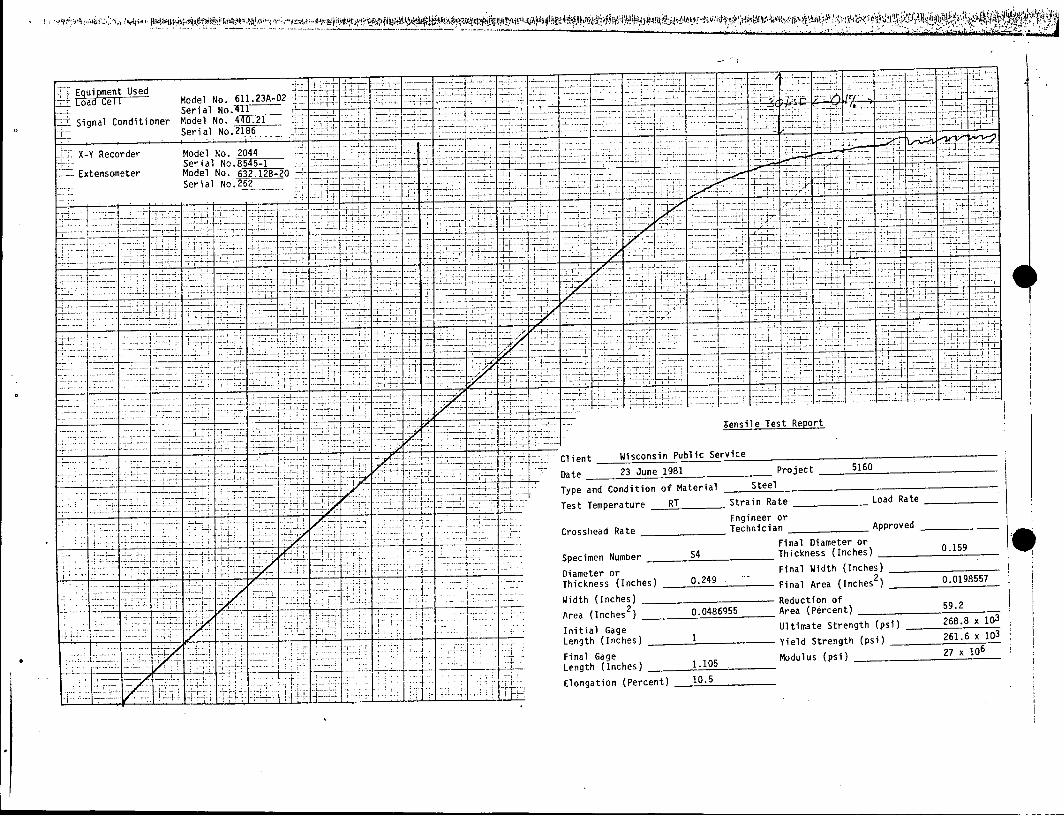
Tensile Test Report
Client Wisconsin Public Service
Date 26 June 1981 Project 5160
Typp and Condition of Material Steel
Test Temperature RT Strain Rate Load Rate
Engineer or Crosshead Rate Technician Approved
Final Diameter or
Specimen Number L4 Thickness (Inches) 0.159
Diameter or Final Width (Inches)
Thickness (Inches) 0.248 Final Area (Inches2 0.0198557
Width (Inches) Reduction of
Area (Inches2 ) 0.0483051 Area (Percent) 58.9
Initial Gage Ultimate Strength (psi) 256.2 x 10³
Length (Inches) 1 Yield Strength (psi) 244.8 x 10³
Final Gage Modulus27.3 x 106
Length (Inches) 1.122
Elongation (Percent) 12.2
j"!
4
- -. - - F r -
-- ------ ----
T-1
-7
~~~~~~~~~~~~~~~~~ . ..................
'~i.' I~ i~ ~ ~ ~ '~
~ ~ ~~.'~
Eaul ment Used pm , usud
Ce I _ -02 oa e Model No. 661.23A
Serial No.411 Signal Conditioner Model No. 440.21 7 7
Serial No.2186
X-Y Recorder Model No. 2044 Serial No. 545-1
Extensometer Model No. 632.12B-20 Serial NO-262
77-7 7 _77
I =iL
7
-- - --- ----- ----- --
_7
-7
7 - 4
D
7
r T:":
-7.
:LL -.LL, I
T,
r-7
7
7-
- ?1
~i7
I
7
- -. I
'.1 - I
J-L I
T
-7
-- - -n
Client Wisconsin Public Service
Date 26 June 1981 Project 5160
Type and Condition of Material Steel
Test Temperature RT Strain Rate _ Load Rate
Engineer or
Crosshead Rate .060 in/min Technician TJD Approved
Final Diameter or
Specimen Number L5 Thickness (Inches)
Diameter or Final Width (Inches)
Thickness (Inches) 0.248 Final Area (Inches )_ 0.0193593
Width (Inches) Reduction of
Area (Inches2) 0.0483051 Area (Percent)
Initial Gage Ultimate Strength (psi) 253.8 x
Length (Inches) 1 Yield Strength (psi) 42.4 x 1
Final Gage Modulus (Psi) 27.6 x 10⁶
Length (Inches) 1.Mu6
Elongation (Percent) 11.1

Equipment Used
Signal Conditioner
Model No. 611.23A-02 Serial No.4TI Model No. 4
SeilN
J 7 i N l A T ~ I ** F4IT. 7* -
- 7 - -' X-Y Recorder Model No. 2044 _____ ____
- Extensometer Model No. 61YTZ.= - ---- -
Serial No.=2r---I
47 I -- ,
I -f
-- ~~ - ---- -----
'-I Ii -T -I-4
-_~ 4'1-~---V---4 .+-~--V---L. 1] ~--iHi~t-X-r~r-iri ~t~1T1Tf77I~
a'
k ± ~~1-
V f-I -i-Ti7ijj' jV-7=
7i11~5-L~-KV- Lz±4z zIg' I ~1'_I ~§Li ti~i -TW:1' I Iit~ 171
- S _____ L..~ -I
I I I -____ ~ ~
7r - - ---1 -
- 7 -; .
w - A
-7-7
-I . - .
A __ I. mil 7,
I L
'A
Th~
r,.
I' ~1~'
- --
1Tensile Test Report
Client Wisconsin Public Service
Date 26 June 1981
Type and Condition of Material Steel
Project 5160
Test Temperature RT Strain Rate Load Rate
Engineer or Crosshead Rate 0.060 in/min Technician TJD Approved
Final Diameter or Specimen Number L7 Thickness (Inches)
Diameter or Final Width (Inches)
Thickness (Inches) 0.248Final Area (Inches2 Width (Inches) Reduction of
Area (Inches2) 0.0483051 Area (Percent) 60.4
Initial Gage Ultimate Strength (psi) 255.6 x 10³
Length (Inches) 1 Yield Strength (psi) 243.6 x 10³
Final Gage Modulus (psi) 28.8 x 10⁶ Length (Inches) 1.129
Elongation (Percent) 12.9
I 7V
44--
K
---- L----
Ii -j
-~1
-I
L
--
-~ :-..~~-
T Equiment Used - oa Used Model No. 611.23A-02
Serial No.TI -4 Signal Conditioner Model No. 44- -V
Serial No.2186
X-Y Recorder Model No. 2044 --Serial No.S43F .
Extensometer Model No. 632.128-20 _R r-o---Serial No.262
4 7 -- -----
_J -7 --- H.. 7 I - -< '-
____ ~ ~ -- 7-~ t__ -1 j j ' i-
t ZLLKIZU~43i lxv____ 4 I--~-4--------4 ~ I
-4H-
7, 1-77A
I--' h -7 z-1b 7 -77f77477jrv7jj~7~7 1-.- F- 'L L - I I
7__-kVVV 4 -1 -#717-
77711 472747 7 7
L- _
17 +jV 4" t111
I -
LL
7 2
9-
Tensile Test Report
Client Wisconsin Public Service
Date 23 June 1981
Type and Condition of Material Steel
Test Temperature RT Strain R
Project 5160
ate
Engineer orCrosshead Rate Technician Approved
Final Diameter or Specimen Number S2 Thickness (Inches) 0.160
Diameter or Final Width (Inches)
Thickness (Inches) 0.2506 Final Area (Inches2) 0.0201062
Width (Inches) Reduction of Area (Inches
2 ) 0.0493233 Area (Percent) 59
Initial Gage Ultimate Strength (psi) 269100 Length (Inches) 1 Yield Strength (psi) 261000
Final Gage 106 Length (Inches) 1.108 M.odulus (psi) 28 x
Elongation (Percent) 10.8
...............
7
f
-- 7
77
4V
Load Rate
..4
fl,4
i.~o i444 K'?.i4
±iECTT
-7Signal Conditioner
X-Y Recorder
Extensometer
-- I. - I- - +
-t-
i.....
1~1-Tl ir~T -J...2 -- 71F T
Model No. 611.23A-02 Serial No. 4TL Model No. 4 02 Serial No.2186 F
Model No. 2044 Serial No.85T5F Model No. 632.12B-20 Serial No.262
-I
-7--
-9
-4
F
I.
-, I-
* F
-7i
7-
--4---. 1.
7- -
7_7 --
-4-4- -4--- - + - I -W
24
U -, T7Z
£ 'J H-I :1.
4-,
-4-4------ + - I ----4-- - t,"- -t - t -~ I 1 T
7- -I c- -v--I- - t 4
~jIA 42
* 1
2-. 4
_J
7I -4
2
_77
:r7
-4
T
7 _T_
--------I
.7T
71-, 2
:1 .. ~ I
T
,
7
7.-.-
'1
FT
FT -I-,
-4.
-U--i
Lb
Hii
Tensile Test Report
Client Wisconsin Public Service
Date 23 June 1981 Project 5160
Type and Condition of Material Steel
Test Temperature RT Strain Rate Load Rate
Engineer or Crosshead Rate Technician Approved
Final Diameter or Specimen Number S4 Thickness (Inches) 0.159
Diameter or Final Width (Inches)
Thickness (Inches) 0.249 Final Area (Inches2) 0.0198557
Width (Inches) Reduction of
Area (Inches2) 0.0486955 Area (Percent) 59.2
Initial Gage Ultimate Strength (psi)
Length (Inches) 1 Yield Strength (psi) 261.6 x 10³
Final Gage Modulus (psi)
Length (Inches) 1.105
Elongation (Percent) 10.5
....
7
-4
-7
7 .
-4-
I I 1 -------- -
7:
...
T
-T--
-+
=J
I I
-:7
-7
17
..
0
ATTACHMENT 3
RELEVANT SECTIONS OF TELEDYNE VASCO LITERATURE, 1972 AND 1981
ENGINEERING SERVICES
'. asc6Max,200 VM' C).7VascoM ax2,50OVM .Vasco*.Max 30 0VM
-1 Ku . . .. VascoMax35
I' ... .. ..
.N7
LARBPENYVN>.55

240
220
200
180
160
-Y 140
120
100
80
60
o 40
2090
104 105 106 107 108 60 Cycles
FIGURE 6. R.R. Moore rotating beam fatigue tests on production bar C stock of VascoMax 250 VM. All samples annealed at 1500*F. for 30
30 minutes, air cooled and aged at 900* F. for 3 hours.
0 5 10 15
Age Time Hours
20 25
FIGURE 5. Effect of Aging Time at 9000F. on the Tensile Properties of VascoMax 250. Specimens solution annealed for 1 hour at 15000F., air cooled and aged at 900*F. for the times indicated.
All ,.ta pertains to bars of small cross section
unless stated otherwise.
Effect of Various Aging Treatments on the Tensile Properties of .125" Thick VascoMax 250 VM Sheet*
Solution .2% Offset Ultimate Reduction Annealing Aging Aging Yield Tensile Elongation, % in. of
Temperature Temperature Time Strength Strength Area OF OF Hours ksi ksi 1" 2" %
1500 850 3 256.7 262.5 9.7 4.7 47.6 1500 900 1 256.6 264.5 9.4 4.8 48.7 1500 900 3 280.2 287.0 8.8 4.5 44.9 1500 900 6 267.5 280.1 8.5 4.2 44.7 1500 950 3 262.3 270.5 9.7 4.5 47.2
Standard ASTM sheet tensiles solution annealed for 30 minutes at the indicated temperatures, air cooled and aged as shown.
FIGURE 7.
13
.E250 C,
U,
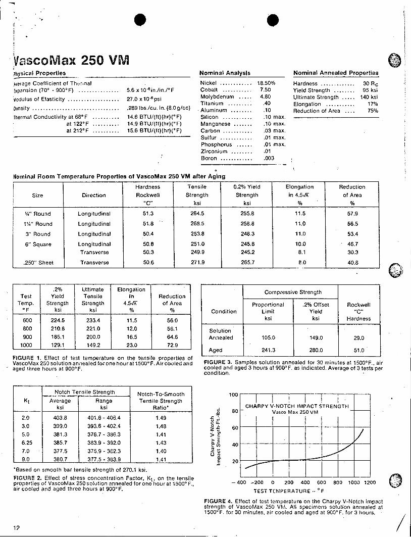
VascoMax 250 VM ?hysical Properties
Aerage Coefficient of Thr.nal Expansion (700 - 900'F) ............... 5.6 x106 in./in./*F
fodulus of Elasticity .................. 27.0 x 10⁻⁶ psi Density ............................ .289 lbs./cu. in. (8.0 g/cc)
Thermal Conductivity at 68*F .......... 14.6 BTU/(ft)(hr)(oF) at 1220F .......... 14.9 BTU/(ft)(hr)(uf) at 212 0 F ........... 15.6 BTU/(ft)(hr)(oF)
Nominal Analysis
Nickel ............ 18.50% Cobalt ........... 7.50 Molybdenum .... 4.80 Titanium ......... .40 Aluminum ........ .10 Silicon ........... .10 max. Manganese ....... .10 max. Carbon ........... .03 max. Sulfur ............ .01 max. Phosphorus ...... .01 max. Zirconium ........ .01 Boron ............ .003
Nominal Annealed Properties
Hardness ............. 30 Rc Yield Strength ........ 95 ksi Ultimate Strength ..... 140 ksi Elongation ........... 17% Reduction of Area .... 75%
Nominal Room Temperature Properties of VascoMax 250 VM after Aging
.2% Ultimate Elongation Test Yield Tensile in Reduction
Temp. Strength Strength 4.5/ of Area oF ksi ksi % %
600 224.5 233.4 11.5 56.0 800 210.8 221.0 12.0 56.1 900 185.1 200.0 16.5 64.6
1000 129.1 149.2 23.0 72.9
FIGURE 1. Effect of test temperature on the tensile properties of VascoMax 250 solution annealed for one hour at 15000 F. Air cooled and aged three hours at 9000F.
Notch Tensile Strength Notch-To-Smooth Kt Average Range Tensile Strength
ksi ksi Ratio*
2.0 403.8 401.6 - 406.4 1.49 3.0 399.0 393.6 - 402.4 1.48 5.0 381.3 376.7 - 386.3 1.41 6.25 385.7 383.9 - 392.0 1.43 7.0 377.5 375.9 - 382.3 1.40 9.0 380.7 377.5 - 383.9 1.41
*Based on smooth bar tensile strength of 270.1 ksi. FIGURE 2. Effect of stress concentration Factor. Kt, on the tensile properties of VascoMax 250 solution annealed for one hour at 15000 F., air cooled and aged three hours at 9000F.
0Compressive Strength
Proportional .2% Offset Rockwell Condition Limit Yield "C"
ksi ksi Hardness
Solution Annealed 105.0 149.0 29.0
Aged 241.3 280.0 51.0
FIGURE 3. Samples solution annealed for 30 minutes at 1500'F., air cooled and aged 3 hours at 9000 F. as indicated. Average of 3 tests per condition.
CLJ
a.E0
100
80
60
40
20
CHARPY V-NOTCH IMPACT STRENGTH Vasco Max 250 VM
-400 -200 0 200 400 600 800 1000 1200 TEST TEMPERATURE - 0 F
FIGURE 4. Effect of test temperature on the Charpy V-Notch impact strength of VascoMax 250 VM. All specimens solution annealed at 1500' F. for 30 minutes, air cooled and aged at 9000 F. for 3 hours.
a
0
VASCO LATROBE, PENNSYLVANIA
A TELEDYNE COMPANY 15650
YoCKE ULTRA WGH STREN TH MAI Rn STELS
e~1
S
0
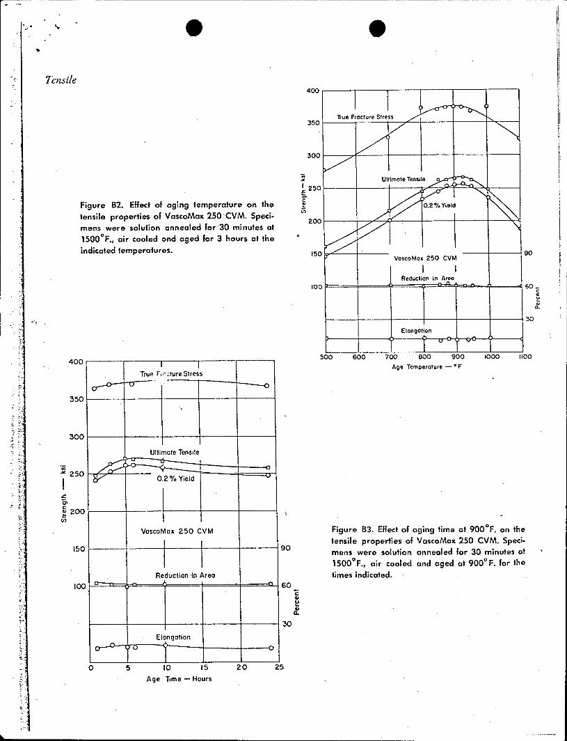
Tensile
I.
Figure B2. Effect of aging temperature on the
tensile properties of VascoMax 250 CVM. Specimens were solution annealed for 30 minutes at 1500 0 F., air cooled and aged for 3 hours at the indicated temperatures.
0 5 10 15 20
Age Temperature -*F
Figure B3. Effect of aging time of 900 0 F. on the tensile properties of VascoMax 250 CVM. Specimens were solution annealed for 30 minutes at 15000F., air cooled and aged at 9000F. for the times indicated.
90
60
C3
30
25
Age Time - Hours
a-
400
350
300
250
200
150
100
I I True Ff -. ure Stress
Ultimate Tensile
0.2% Yield
VascoMax 250 CVM
Reduction in Area
Elongation

9 S
CHARPY V-NOTCH IMPACT STRENGTH
Vasco Max, 250 CVM
100
4 I
80 4
C
n) 60
E 40
0
0.
-4 0 200 400 600 800 1000 1200
Test Temperature -*F
Figure B4. Effect of test temperature on the Charpy V-notch impact strength of VascoMax 250 CVM. All specimens solution annealed at 15000 F. for 30 minutes, air cooled and aged at 9000 F. for 3 hours.
Table B2 COMPRESSIVE STRENGTH OF VascoMax 250 CVM
Samples solution annealed for 30 minutes at 1500*F., air cooled and aged 3 hours at 9000F. as indicated. Average of 3 tests per condition.
Coinpressive Strength
Proportional .2%, Offset Rockwell Limit Yield "C"
Condition ksi ksi Hardness
Solution Annealed . . . . . 105.0 149.0 29.0
Aged . . . . . . . 241.3 280.0 51.0
Impact Compression
F ~ -*~- .- ~
00 -200