mechanical systems grid #2 static load test test ... 1 glast lat project october 13, 2005 mechanical...
TRANSCRIPT

LAT-PR-07492 1
GLAST LAT Project October 13, 2005
Mechanical Systems
Grid #2 Static Load TestTest Readiness Review
October 13, 2005
Mechanical SystemsMechanical Systems
Grid #2 Static Load TestGrid #2 Static Load TestTest Readiness ReviewTest Readiness Review
October 13, 2005October 13, 2005
Marc Campell [email protected] Ku [email protected]
Mike Springer [email protected]
Marc Campell [email protected] Ku [email protected]
Mike Springer [email protected]
LAT-PR-07492 2
GLAST LAT Project October 13, 2005
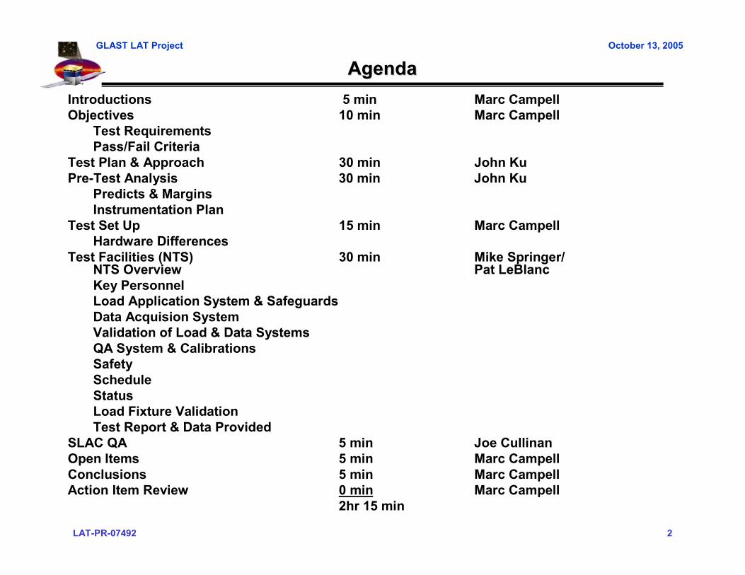
AgendaAgendaIntroductions 5 min Marc CampellObjectives 10 min Marc Campell
Test RequirementsPass/Fail Criteria
Test Plan & Approach 30 min John KuPre-Test Analysis 30 min John Ku
Predicts & MarginsInstrumentation Plan
Test Set Up 15 min Marc CampellHardware Differences
Test Facilities (NTS) 30 min Mike Springer/ NTS Overview Pat LeBlancKey PersonnelLoad Application System & SafeguardsData Acquision SystemValidation of Load & Data SystemsQA System & CalibrationsSafety ScheduleStatusLoad Fixture ValidationTest Report & Data Provided
SLAC QA 5 min Joe CullinanOpen Items 5 min Marc CampellConclusions 5 min Marc CampellAction Item Review 0 min Marc Campell
2hr 15 min
LAT-PR-07492 3
GLAST LAT Project October 13, 2005
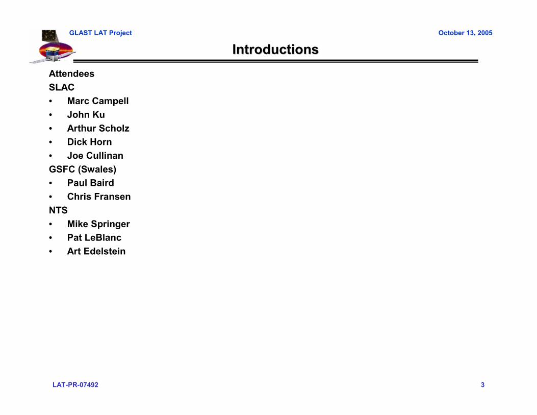
IntroductionsIntroductionsAttendeesSLAC• Marc Campell• John Ku• Arthur Scholz• Dick Horn• Joe CullinanGSFC (Swales)• Paul Baird • Chris FransenNTS• Mike Springer• Pat LeBlanc• Art Edelstein
LAT-PR-07492 4
GLAST LAT Project October 13, 2005
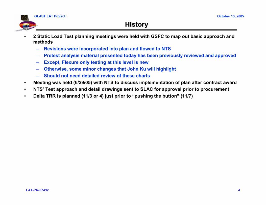
HistoryHistory• 2 Static Load Test planning meetings were held with GSFC to map out basic approach and
methods– Revisions were incorporated into plan and flowed to NTS– Pretest analysis material presented today has been previously reviewed and approved– Except, Flexure only testing at this level is new– Otherwise, some minor changes that John Ku will highlight– Should not need detailed review of these charts
• Meeting was held (6/29/05) with NTS to discuss implementation of plan after contract award• NTS’ Test approach and detail drawings sent to SLAC for approval prior to procurement• Delta TRR is planned (11/3 or 4) just prior to “pushing the button” (11/7)

LAT-PR-07492 5
GLAST LAT Project October 13, 2005
Test ObjectivesTest Objectives
• Primary objective: verify static strength and stability of the Grid box assembly under worst case Delta II-H vehicle loads of 1.25 times limit loads
– Envelope worst case loads and stresses near spacecraft mount– Load required subsystem interfaces to qualification design loads
LAT-PR-07492 6
GLAST LAT Project October 13, 2005
Test ObjectivesTest Objectives
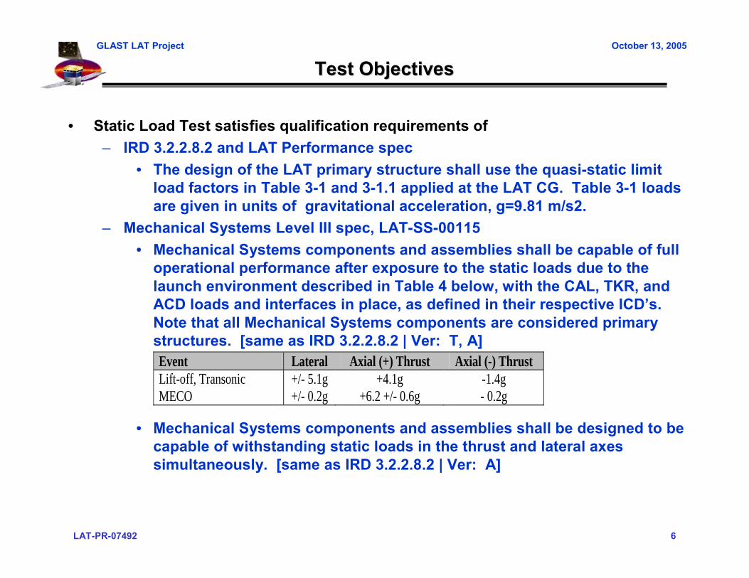
• Static Load Test satisfies qualification requirements of– IRD 3.2.2.8.2 and LAT Performance spec
• The design of the LAT primary structure shall use the quasi-static limit load factors in Table 3-1 and 3-1.1 applied at the LAT CG. Table 3-1 loads are given in units of gravitational acceleration, g=9.81 m/s2.
– Mechanical Systems Level III spec, LAT-SS-00115• Mechanical Systems components and assemblies shall be capable of full
operational performance after exposure to the static loads due to the launch environment described in Table 4 below, with the CAL, TKR, and ACD loads and interfaces in place, as defined in their respective ICD’s. Note that all Mechanical Systems components are considered primary structures. [same as IRD 3.2.2.8.2 | Ver: T, A]
• Mechanical Systems components and assemblies shall be designed to be capable of withstanding static loads in the thrust and lateral axes simultaneously. [same as IRD 3.2.2.8.2 | Ver: A]
Event Lateral Axial (+) Thrust Axial (-) Thrust Lift-off, Transonic +/- 5.1g +4.1g -1.4g MECO +/- 0.2g +6.2 +/- 0.6g - 0.2g

LAT-PR-07492 7
GLAST LAT Project October 13, 2005
Test Objectives (cont)Test Objectives (cont)
• Grid Interfaces verified in this test– CAL-Grid– Spacecraft – Grid– Radiator – Grid (Radiator Mount Bracket)
• Grid Interfaces not verified in this test– Tracker – Grid – ACD – Grid

LAT-PR-07492 8
GLAST LAT Project October 13, 2005
Test Objectives (cont)Test Objectives (cont)
Secondary Objectives• Grid Math Model Validation
– Comparing measured strains and deflections to predictions from the integrated LAT finite element analysis model
– LAT model will be updated, if required• Test Interface Plate (TIP) validation
– TIP is used to transport the LAT and as an interface between all test fixtures for LAT environmental tests
– TIP must be proof loaded– TIP flexure strain gage calibration
• These gages used to determine loads into LAT during LAT Sine Vibe testing

LAT-PR-07492 9
GLAST LAT Project October 13, 2005
Pass/Fail CriteriaPass/Fail Criteria
• Completion of all load cases • A review of all pertinent data during the test, including deflections and strains to
verify linearity and return to zero.• Verified that no yielding, buckling, de-bonding or fractures have been observed.
– A visual inspection is to be performed after each load case• Load Case 5 & 6 without CAL plates is for model verification purposes only (no
pass/fail)

LAT-PR-07492 10
GLAST LAT Project October 13, 2005
Mechanical Systems
Grid #2 Static Load TestTest Readiness Review
Test Plan and Pre-test Analysis
Mechanical SystemsMechanical Systems
Grid #2 Static Load TestGrid #2 Static Load TestTest Readiness ReviewTest Readiness Review
Test Plan and PreTest Plan and Pre--test Analysistest Analysis
John Ku [email protected] Ku [email protected]

LAT-PR-07492 11
GLAST LAT Project October 13, 2005
Load Cases and Required STELoad Cases and Required STE• Load Cases currently planned for:
– Proof TestsLC7a – LC7h – SC Flexure Max Tension and Max Compression
– Strength TestsLC1a - Flight loads at SC mount – On Flexures With Cal-Plates – Max CompressionLC1b - Flight loads at SC mount – On Flexures With Cal-Plates – Max TensionLC1c – Shear only at SC mount – On Flexures With Cal-Plates – Max ShearLC2a - Lift loads at RMB – On Flexures With Cal-Plates +ZLC2b - Lift loads at RMB – On Flexures With Cal-Plates -Z
– Stiffness TestsLC3 - Drum-head stiffness: hold at SC mount and push on center – With Cal-Plates, No FlexuresLC4 - Torsional stiffness: hold at SC mount and push on center – With Cal-Plates , No FlexuresLC5 - Torsional stiffness: hold at SC mount and push on center – No Cal-Plates , No FlexuresLC6 - Drum-head stiffness: hold at SC mount and push on center – No Cal-Plates , No Flexures
• Required Specialized Test Equipment– Flexures (Flight-like; provided by Spectrum Astro)– Test Interface Plate (to hold bottom of flexure)– EMI Simulators– XLAT Simulators– Cal Plate Simulators– Load Fixtures (Provided by NTS)
LAT-PR-07492 12
GLAST LAT Project October 13, 2005
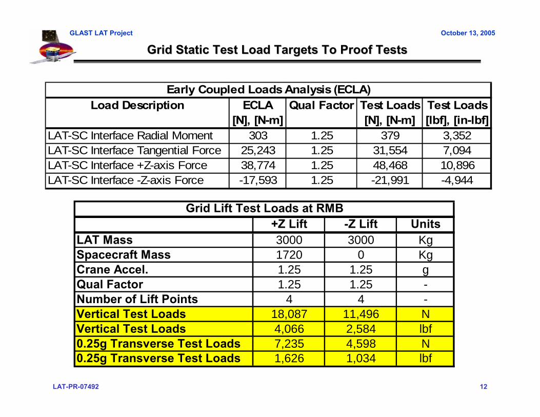
Grid Static Test Load Targets To Proof TestsGrid Static Test Load Targets To Proof Tests
Load Description ECLA Qual Factor Test Loads Test Loads[N], [N-m] [N], [N-m] [lbf], [in-lbf]
LAT-SC Interface Radial Moment 303 1.25 379 3,352LAT-SC Interface Tangential Force 25,243 1.25 31,554 7,094LAT-SC Interface +Z-axis Force 38,774 1.25 48,468 10,896LAT-SC Interface -Z-axis Force -17,593 1.25 -21,991 -4,944
Early Coupled Loads Analysis (ECLA)
+Z Lift -Z Lift UnitsLAT Mass 3000 3000 KgSpacecraft Mass 1720 0 KgCrane Accel. 1.25 1.25 gQual Factor 1.25 1.25 -Number of Lift Points 4 4 -Vertical Test Loads 18,087 11,496 NVertical Test Loads 4,066 2,584 lbf0.25g Transverse Test Loads 7,235 4,598 N0.25g Transverse Test Loads 1,626 1,034 lbf
Grid Lift Test Loads at RMB
LAT-PR-07492 13
GLAST LAT Project October 13, 2005
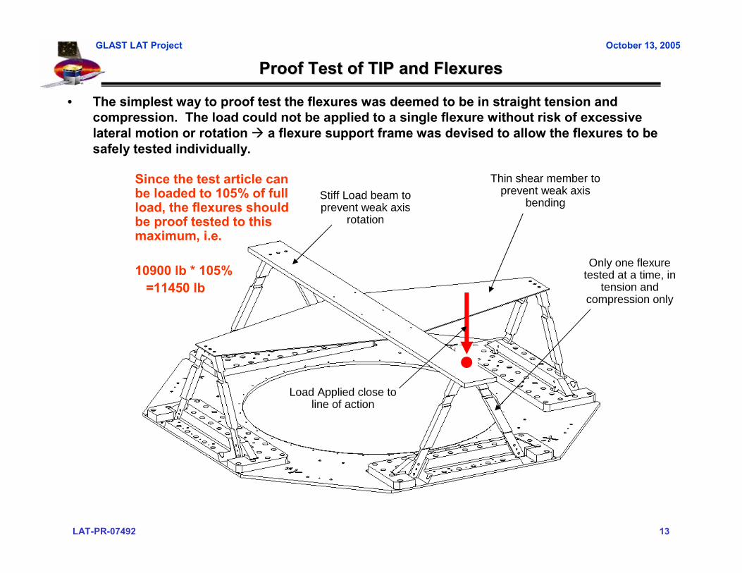
Proof Test of TIP and FlexuresProof Test of TIP and Flexures
• The simplest way to proof test the flexures was deemed to be in straight tension and compression. The load could not be applied to a single flexure without risk of excessive lateral motion or rotation a flexure support frame was devised to allow the flexures to besafely tested individually.
Stiff Load beam to prevent weak axis
rotation
Thin shear member to prevent weak axis
bending
Only one flexure tested at a time, in
tension and compression only
Load Applied close to line of action
Since the test article can be loaded to 105% of full load, the flexures should be proof tested to this maximum, i.e.
10900 lb * 105%=11450 lb
LAT-PR-07492 14
GLAST LAT Project October 13, 2005
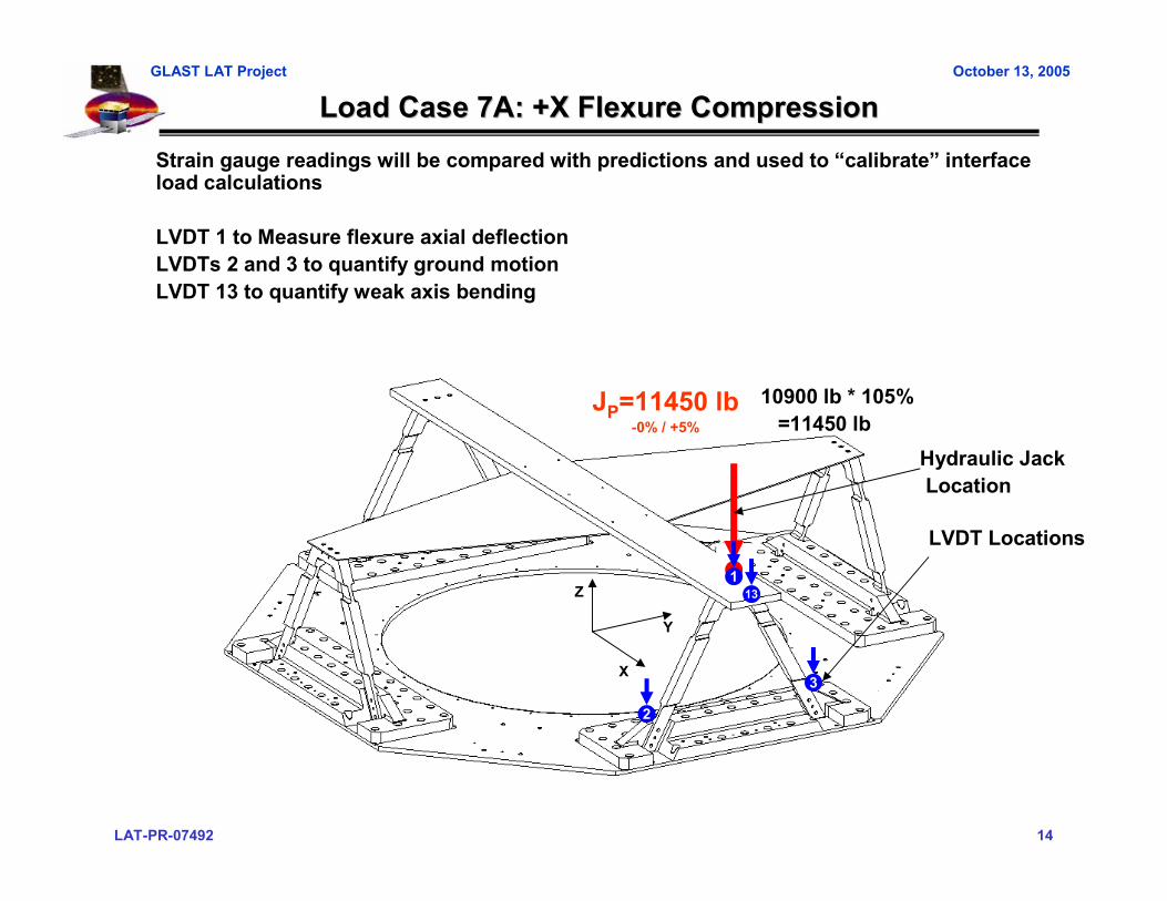
JP=11450 lb-0% / +5%
Load Case 7A: +X Flexure CompressionLoad Case 7A: +X Flexure Compression
Z
Y
X
Strain gauge readings will be compared with predictions and used to “calibrate” interface load calculations
LVDT 1 to Measure flexure axial deflectionLVDTs 2 and 3 to quantify ground motionLVDT 13 to quantify weak axis bending
10900 lb * 105%=11450 lb
2
3
113
LVDT Locations
Hydraulic JackLocation
LAT-PR-07492 15
GLAST LAT Project October 13, 2005
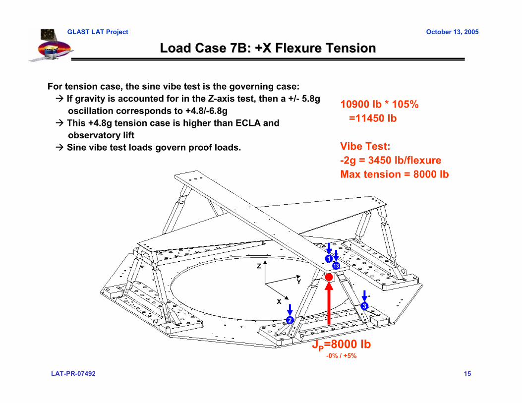
Load Case 7B: +X Flexure TensionLoad Case 7B: +X Flexure Tension
JP=8000 lb-0% / +5%
Z
Y
X
10900 lb * 105%=11450 lb
Vibe Test:-2g = 3450 lb/flexureMax tension = 8000 lb
2
3
113
For tension case, the sine vibe test is the governing case:If gravity is accounted for in the Z-axis test, then a +/- 5.8goscillation corresponds to +4.8/-6.8gThis +4.8g tension case is higher than ECLA and observatory lift Sine vibe test loads govern proof loads.

LAT-PR-07492 16
GLAST LAT Project October 13, 2005
0% 20% 40% 60% 80% 90% 100% 90% 80% 60% 40% 20% 0%JP Predicted 0 -2290 -4580 -6870 -9160 -10305 -11450 -10305 -9160 -6870 -4580 -2290 0
MeasuredLVDT 1 Predicted
MeasuredLVDT 2 Predicted
MeasuredLVDT 3 Predicted
MeasuredLVDT 13 Predicted
Measured
LC7A and LC7B Test FlowLC7A and LC7B Test Flow
• Zero instrumentation channels and verify they are functioning properly• Begin LC7A compression case by applying 40% load in the following increments:
– 0% 10% 20% 30% 40%– 40% 20% 0%
• If data is within 25% of predictions, continue to next step; else, sharpen pencil• Re-zero instrumentation channels and apply 100% load in the following increments:
– 0% 20% 40% 60% 80% 90% 100%– 100% 80% 60% 40% 20% 0%
• Without zeroing data, continue on to LC7B compression case:– 0% -20% -40% -60% -80% -90% -100%– -100% -80% -60% -40% -20% 0%
• Plot Load vs. Displacement and Load vs. Strain for all channels (should be closed loop)• Example Data Sheet Shown Below (pick critical channels to watch):
Fill in tables with LVDT and SG Predicts (TBD)Each LC will have its own Data Sheet
0% -20% -40% -60% -80% -90% -100% -90% -80% -60% -40% -20% 0%JP Predicted 0 1600 3200 4800 6400 7200 8000 7200 6400 4800 3200 1600 0
MeasuredLVDT 1 Predicted
MeasuredLVDT 2 Predicted
MeasuredLVDT 3 Predicted
MeasuredLVDT 13 Predicted
Measured
LAT-PR-07492 17
GLAST LAT Project October 13, 2005
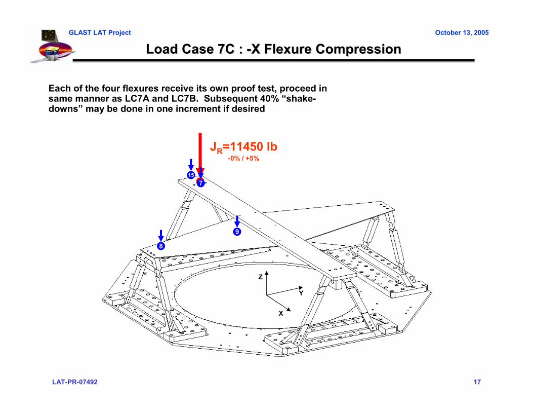
Load Case 7C : Load Case 7C : --X Flexure CompressionX Flexure Compression
JR=11450 lb-0% / +5%
Z
Y
X
8
9
715
Each of the four flexures receive its own proof test, proceed insame manner as LC7A and LC7B. Subsequent 40% “shake-downs” may be done in one increment if desired
LAT-PR-07492 18
GLAST LAT Project October 13, 2005
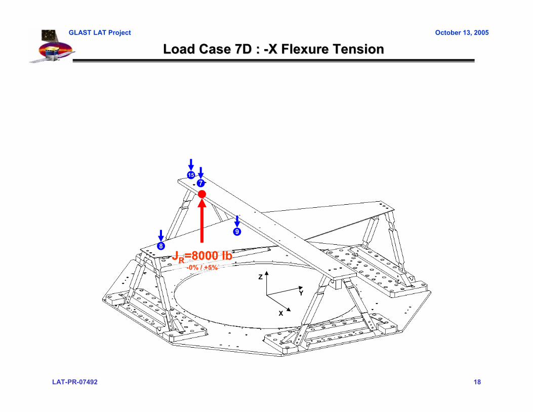
Load Case 7D : Load Case 7D : --X Flexure TensionX Flexure Tension
JR=8000 lb-0% / +5%
Z
Y
X
8
9
715
LAT-PR-07492 19
GLAST LAT Project October 13, 2005
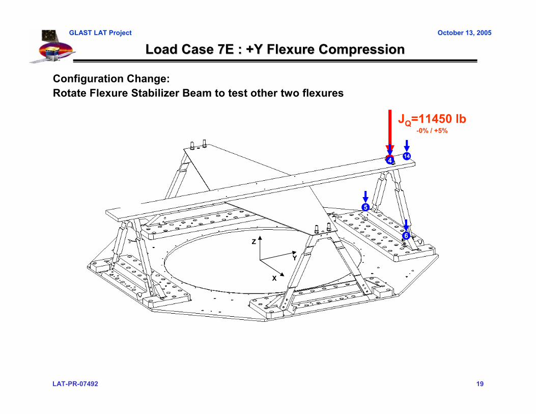
Load Case 7E : +Y Flexure CompressionLoad Case 7E : +Y Flexure Compression
JQ=11450 lb-0% / +5%
Z
Y
X
Configuration Change:Rotate Flexure Stabilizer Beam to test other two flexures
5
6
4 14
LAT-PR-07492 20
GLAST LAT Project October 13, 2005
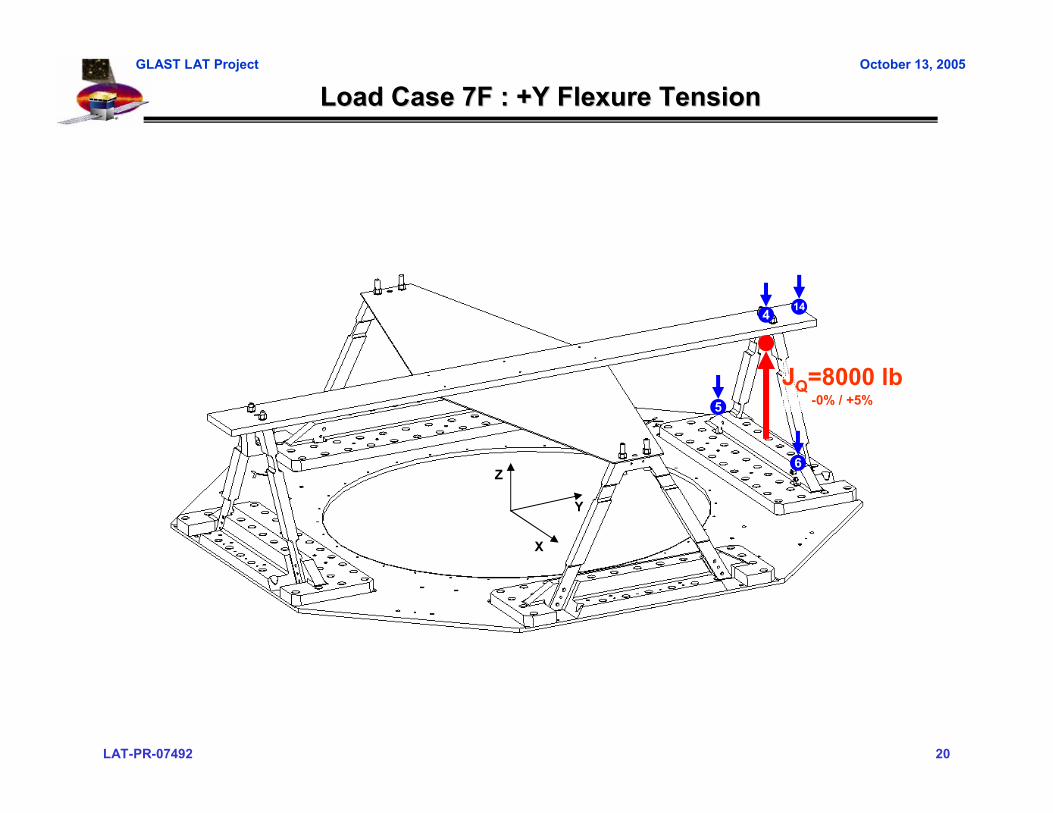
Load Case 7F : +Y Flexure TensionLoad Case 7F : +Y Flexure Tension
JQ=8000 lb-0% / +5%
Z
Y
X
5
6
4 14

LAT-PR-07492 21
GLAST LAT Project October 13, 2005
Load Case 7G : Load Case 7G : --Y Flexure CompressionY Flexure Compression
JS=11450 lb-0% / +5%
Z
Y
X
11
12
1016
LAT-PR-07492 22
GLAST LAT Project October 13, 2005
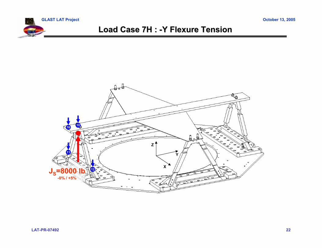
Load Case 7H : Load Case 7H : --Y Flexure TensionY Flexure Tension
JS=8000 lb-0% / +5%
Z
Y
X
11
12
1016
LAT-PR-07492 23
GLAST LAT Project October 13, 2005
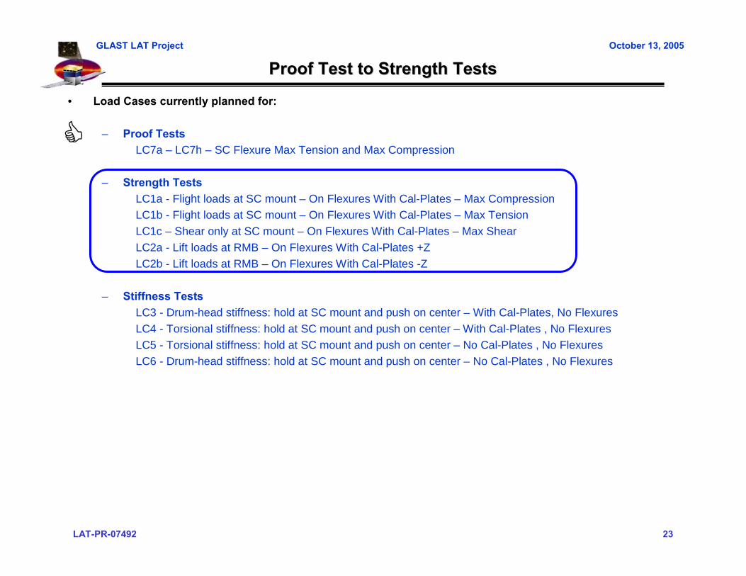
Proof Test to Strength TestsProof Test to Strength Tests
• Load Cases currently planned for:
– Proof TestsLC7a – LC7h – SC Flexure Max Tension and Max Compression
– Strength TestsLC1a - Flight loads at SC mount – On Flexures With Cal-Plates – Max CompressionLC1b - Flight loads at SC mount – On Flexures With Cal-Plates – Max TensionLC1c – Shear only at SC mount – On Flexures With Cal-Plates – Max ShearLC2a - Lift loads at RMB – On Flexures With Cal-Plates +ZLC2b - Lift loads at RMB – On Flexures With Cal-Plates -Z
– Stiffness TestsLC3 - Drum-head stiffness: hold at SC mount and push on center – With Cal-Plates, No FlexuresLC4 - Torsional stiffness: hold at SC mount and push on center – With Cal-Plates , No FlexuresLC5 - Torsional stiffness: hold at SC mount and push on center – No Cal-Plates , No FlexuresLC6 - Drum-head stiffness: hold at SC mount and push on center – No Cal-Plates , No Flexures
LAT-PR-07492 24
GLAST LAT Project October 13, 2005
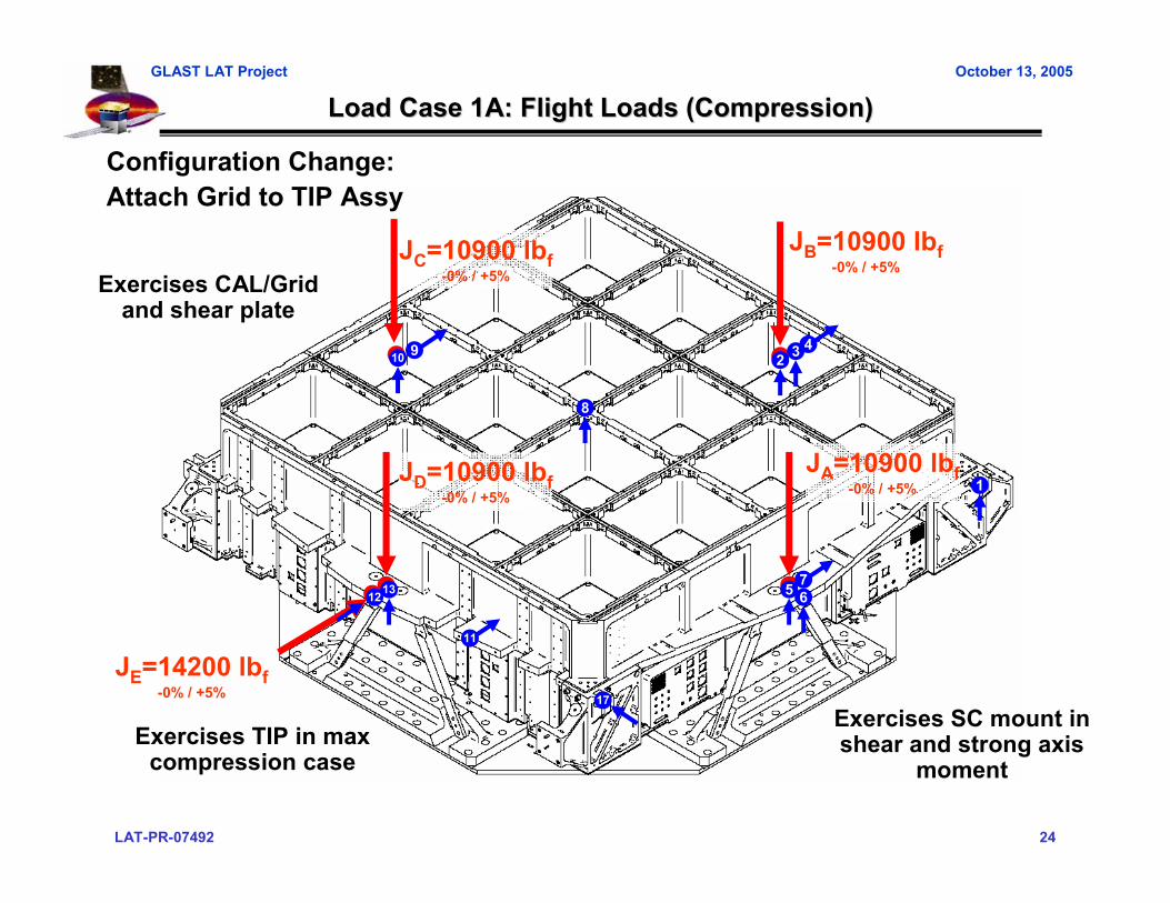
Load Case 1A: Flight Loads (Compression)Load Case 1A: Flight Loads (Compression)
JE=14200 lbf-0% / +5%
JC=10900 lbf-0% / +5%
JB=10900 lbf-0% / +5%
JA=10900 lbf-0% / +5%
JD=10900 lbf-0% / +5%
1312 5
29
17
1
3 4
67
8
10
11
Configuration Change:Attach Grid to TIP Assy
Exercises SC mount in shear and strong axis
momentExercises TIP in max
compression case
Exercises CAL/Grid and shear plate

LAT-PR-07492 25
GLAST LAT Project October 13, 2005
Load Case 1A: Flight Loads (Compression)Load Case 1A: Flight Loads (Compression)
• Finite Element model uses latest LAT models, with modifications made to match test configuration
– Calculated displacements and strains compared to measures values
Displacements
FEA Model
Strains
Max Z Disp = 31.0 milMax Y Disp = 37.0 mil
Max Stress = 24.2 ksi(Conservatively)

LAT-PR-07492 26
GLAST LAT Project October 13, 2005
Load Case 1A: Flight Loads (Compression)Load Case 1A: Flight Loads (Compression)
0% 20% 40% 60% 80% 90% 100% 90% 80% 60% 40% 20% 0%JP Predicted 0 -2290 -4580 -6870 -9160 -10305 -11450 -10305 -9160 -6870 -4580 -2290 0
MeasuredLVDT 1 Predicted
MeasuredLVDT 2 Predicted
MeasuredLVDT 3 Predicted
MeasuredLVDT 13 Predicted
Measured
• Zero instrumentation channels and verify they are functioning properly• Begin LC7A compression case by applying 40% load in the following increments:
– 0% 10% 20% 30% 40%– 40% 20% 0%
• If data is within 25% of predictions, continue to next step; else, sharpen pencil• Re-zero instrumentation channels and apply 100% load in the following increments:
– 0% 20% 40% 60% 80% 90% 100%– 100% 80% 60% 40% 20% 0%
• Without zeroing data, continue on to LC7B compression case:– 0% -20% -40% -60% -80% -90% -100%– -100% -80% -60% -40% -20% 0%
• Plot Load vs. Displacement and Load vs. Strain for all channels (should be closed loop)• Example Data Sheet Shown Below (pick critical channels to watch):
Fill in tables with LVDT and SG Predicts (TBD)Each LC will have its own Data Sheet
0% -20% -40% -60% -80% -90% -100% -90% -80% -60% -40% -20% 0%JP Predicted 0 1600 3200 4800 6400 7200 8000 7200 6400 4800 3200 1600 0
MeasuredLVDT 1 Predicted
MeasuredLVDT 2 Predicted
MeasuredLVDT 3 Predicted
MeasuredLVDT 13 Predicted
Measured
LAT-PR-07492 27
GLAST LAT Project October 13, 2005
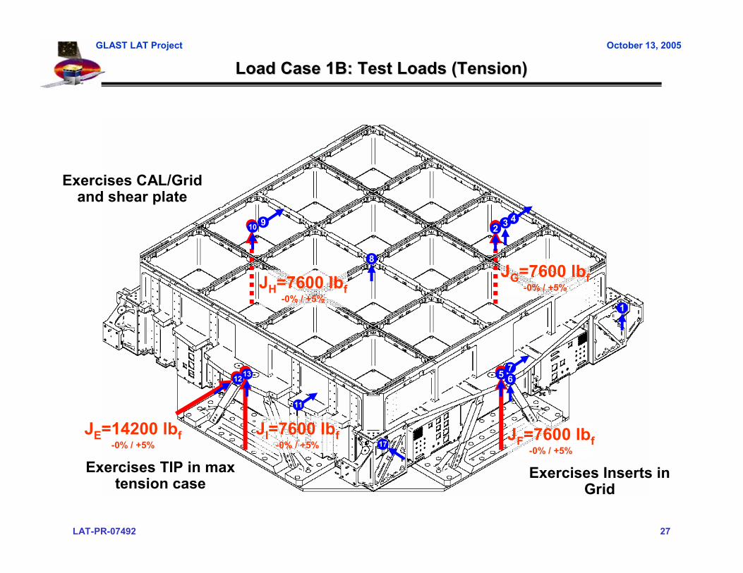
Load Case 1B: Test Loads (Tension)Load Case 1B: Test Loads (Tension)
JE=14200 lbf-0% / +5%
JH=7600 lbf-0% / +5%
JG=7600 lbf-0% / +5%
JF=7600 lbf-0% / +5%
JI=7600 lbf-0% / +5%
1312 5
29
17
1
3 4
67
8
10
11
Exercises Inserts in Grid
Exercises TIP in max tension case
Exercises CAL/Grid and shear plate

LAT-PR-07492 28
GLAST LAT Project October 13, 2005
Load Case 1B: Test Loads (Tension)Load Case 1B: Test Loads (Tension)
• Finite Element model uses latest LAT models, with modifications made to match test configuration
– Calculated displacements and strains compared to measures values
Displacements
FEA Model
Strains
Max Z Disp = 13.5 milMax Y Disp = 35.4 mil
Max Stress = 18.7 ksi(Conservatively)
LAT-PR-07492 29
GLAST LAT Project October 13, 2005
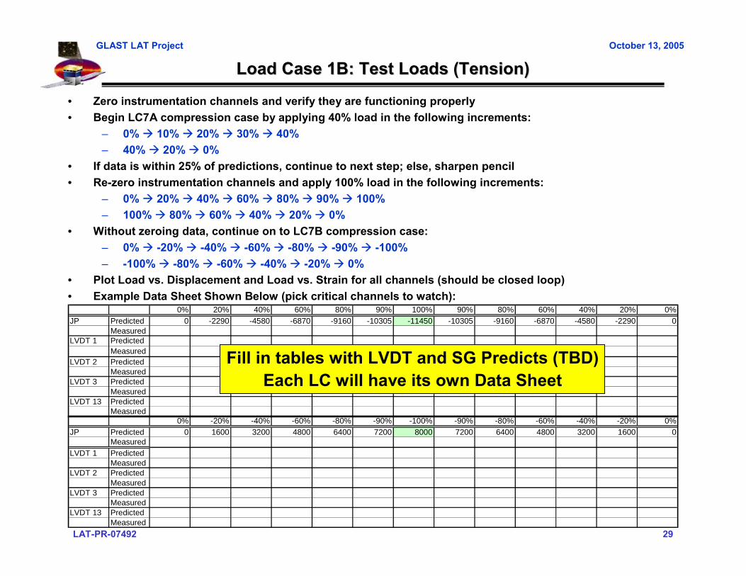
Load Case 1B: Test Loads (Tension)Load Case 1B: Test Loads (Tension)
0% 20% 40% 60% 80% 90% 100% 90% 80% 60% 40% 20% 0%JP Predicted 0 -2290 -4580 -6870 -9160 -10305 -11450 -10305 -9160 -6870 -4580 -2290 0
MeasuredLVDT 1 Predicted
MeasuredLVDT 2 Predicted
MeasuredLVDT 3 Predicted
MeasuredLVDT 13 Predicted
Measured
• Zero instrumentation channels and verify they are functioning properly• Begin LC7A compression case by applying 40% load in the following increments:
– 0% 10% 20% 30% 40%– 40% 20% 0%
• If data is within 25% of predictions, continue to next step; else, sharpen pencil• Re-zero instrumentation channels and apply 100% load in the following increments:
– 0% 20% 40% 60% 80% 90% 100%– 100% 80% 60% 40% 20% 0%
• Without zeroing data, continue on to LC7B compression case:– 0% -20% -40% -60% -80% -90% -100%– -100% -80% -60% -40% -20% 0%
• Plot Load vs. Displacement and Load vs. Strain for all channels (should be closed loop)• Example Data Sheet Shown Below (pick critical channels to watch):
Fill in tables with LVDT and SG Predicts (TBD)Each LC will have its own Data Sheet
0% -20% -40% -60% -80% -90% -100% -90% -80% -60% -40% -20% 0%JP Predicted 0 1600 3200 4800 6400 7200 8000 7200 6400 4800 3200 1600 0
MeasuredLVDT 1 Predicted
MeasuredLVDT 2 Predicted
MeasuredLVDT 3 Predicted
MeasuredLVDT 13 Predicted
Measured
LAT-PR-07492 30
GLAST LAT Project October 13, 2005
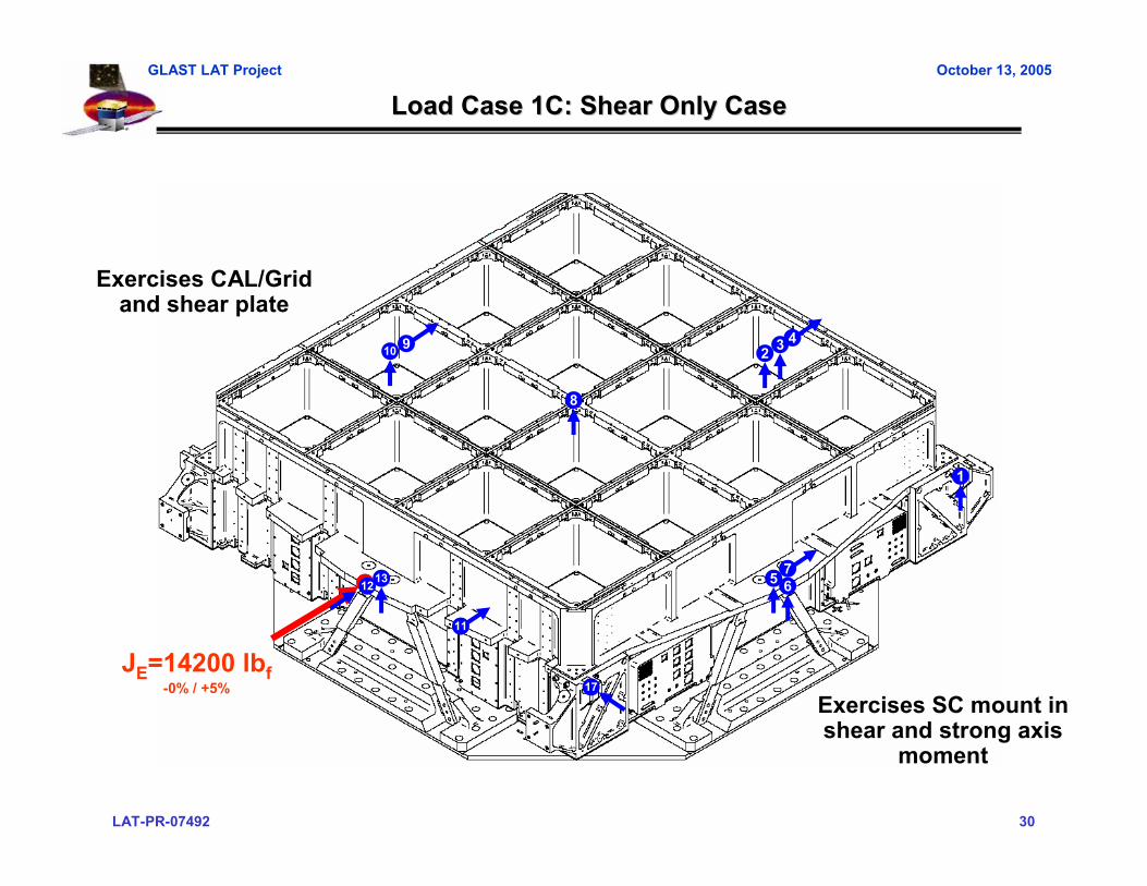
Load Case 1C: Shear Only CaseLoad Case 1C: Shear Only Case
JE=14200 lbf-0% / +5%
1312 5
29
17
1
3 4
67
8
10
11
Exercises CAL/Grid and shear plate
Exercises SC mount in shear and strong axis
moment
LAT-PR-07492 31
GLAST LAT Project October 13, 2005
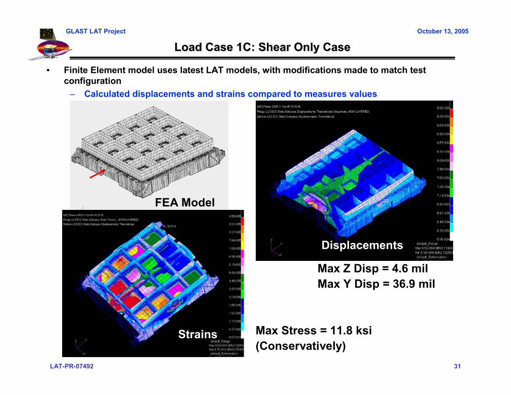
Load Case 1C: Shear Only CaseLoad Case 1C: Shear Only Case
• Finite Element model uses latest LAT models, with modifications made to match test configuration
– Calculated displacements and strains compared to measures values
Displacements
FEA Model
Strains
Max Z Disp = 4.6 milMax Y Disp = 36.9 mil
Max Stress = 11.8 ksi(Conservatively)

LAT-PR-07492 32
GLAST LAT Project October 13, 2005
Load Case 1C: Shear Only CaseLoad Case 1C: Shear Only Case
0% 20% 40% 60% 80% 90% 100% 90% 80% 60% 40% 20% 0%JP Predicted 0 -2290 -4580 -6870 -9160 -10305 -11450 -10305 -9160 -6870 -4580 -2290 0
MeasuredLVDT 1 Predicted
MeasuredLVDT 2 Predicted
MeasuredLVDT 3 Predicted
MeasuredLVDT 13 Predicted
Measured
• Zero instrumentation channels and verify they are functioning properly• Begin LC7A compression case by applying 40% load in the following increments:
– 0% 10% 20% 30% 40%– 40% 20% 0%
• If data is within 25% of predictions, continue to next step; else, sharpen pencil• Re-zero instrumentation channels and apply 100% load in the following increments:
– 0% 20% 40% 60% 80% 90% 100%– 100% 80% 60% 40% 20% 0%
• Without zeroing data, continue on to LC7B compression case:– 0% -20% -40% -60% -80% -90% -100%– -100% -80% -60% -40% -20% 0%
• Plot Load vs. Displacement and Load vs. Strain for all channels (should be closed loop)• Example Data Sheet Shown Below (pick critical channels to watch):
Fill in tables with LVDT and SG Predicts (TBD)Each LC will have its own Data Sheet
0% -20% -40% -60% -80% -90% -100% -90% -80% -60% -40% -20% 0%JP Predicted 0 1600 3200 4800 6400 7200 8000 7200 6400 4800 3200 1600 0
MeasuredLVDT 1 Predicted
MeasuredLVDT 2 Predicted
MeasuredLVDT 3 Predicted
MeasuredLVDT 13 Predicted
Measured

LAT-PR-07492 33
GLAST LAT Project October 13, 2005
Load Case 2A: Observatory Lift CaseLoad Case 2A: Observatory Lift Case
JN2=1650 lbf-0% / +5%
JK2=1650 lbf-0% / +5%
JN1=4100 lbf-0% / +5%
JK1=4100 lbf-0% / +5%
JM=4100 lbf-0% / +5%
JL=4100 lbf-0% / +5%
13 5
2
18
1
3
6
8
10
14
15
16
17
19
Exercises Inserts in Grid
Exercises CAL/Grid and shear plate
Exercises Grid corner, RMB, EMI Skirts and XLAT
Plate
LAT-PR-07492 34
GLAST LAT Project October 13, 2005
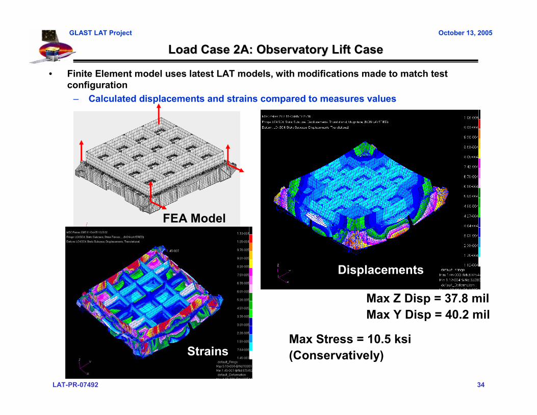
Load Case 2A: Observatory Lift CaseLoad Case 2A: Observatory Lift Case
• Finite Element model uses latest LAT models, with modifications made to match test configuration
– Calculated displacements and strains compared to measures values
Displacements
FEA Model
Max Z Disp = 37.8 milMax Y Disp = 40.2 mil
Max Stress = 10.5 ksi(Conservatively)Strains

LAT-PR-07492 35
GLAST LAT Project October 13, 2005
Load Case 2A: Observatory Lift CaseLoad Case 2A: Observatory Lift Case
0% 20% 40% 60% 80% 90% 100% 90% 80% 60% 40% 20% 0%JP Predicted 0 -2290 -4580 -6870 -9160 -10305 -11450 -10305 -9160 -6870 -4580 -2290 0
MeasuredLVDT 1 Predicted
MeasuredLVDT 2 Predicted
MeasuredLVDT 3 Predicted
MeasuredLVDT 13 Predicted
Measured
• Zero instrumentation channels and verify they are functioning properly• Begin LC7A compression case by applying 40% load in the following increments:
– 0% 10% 20% 30% 40%– 40% 20% 0%
• If data is within 25% of predictions, continue to next step; else, sharpen pencil• Re-zero instrumentation channels and apply 100% load in the following increments:
– 0% 20% 40% 60% 80% 90% 100%– 100% 80% 60% 40% 20% 0%
• Without zeroing data, continue on to LC7B compression case:– 0% -20% -40% -60% -80% -90% -100%– -100% -80% -60% -40% -20% 0%
• Plot Load vs. Displacement and Load vs. Strain for all channels (should be closed loop)• Example Data Sheet Shown Below (pick critical channels to watch):
Fill in tables with LVDT and SG Predicts (TBD)Each LC will have its own Data Sheet
0% -20% -40% -60% -80% -90% -100% -90% -80% -60% -40% -20% 0%JP Predicted 0 1600 3200 4800 6400 7200 8000 7200 6400 4800 3200 1600 0
MeasuredLVDT 1 Predicted
MeasuredLVDT 2 Predicted
MeasuredLVDT 3 Predicted
MeasuredLVDT 13 Predicted
Measured

LAT-PR-07492 36
GLAST LAT Project October 13, 2005
Load Case 2B: LAT Load Case 2B: LAT ““Upside DownUpside Down”” Case (I&T Only)Case (I&T Only)
JN2=1050 lbf-0% / +5%
JK2=1050 lbf-0% / +5%
JN1=2600 lbf-0% / +5%
JK1=2600 lbf-0% / +5%
JM=2600 lbf-0% / +5%
JL=2600 lbf-0% / +5%
13 5
2
18
1
3
6
8
10
14
15
16
17
19
Exercises Inserts in Grid
Exercises CAL/Grid and shear plate
Exercises Grid corner, RMB, EMI Skirts and XLAT
Plate
LAT-PR-07492 37
GLAST LAT Project October 13, 2005
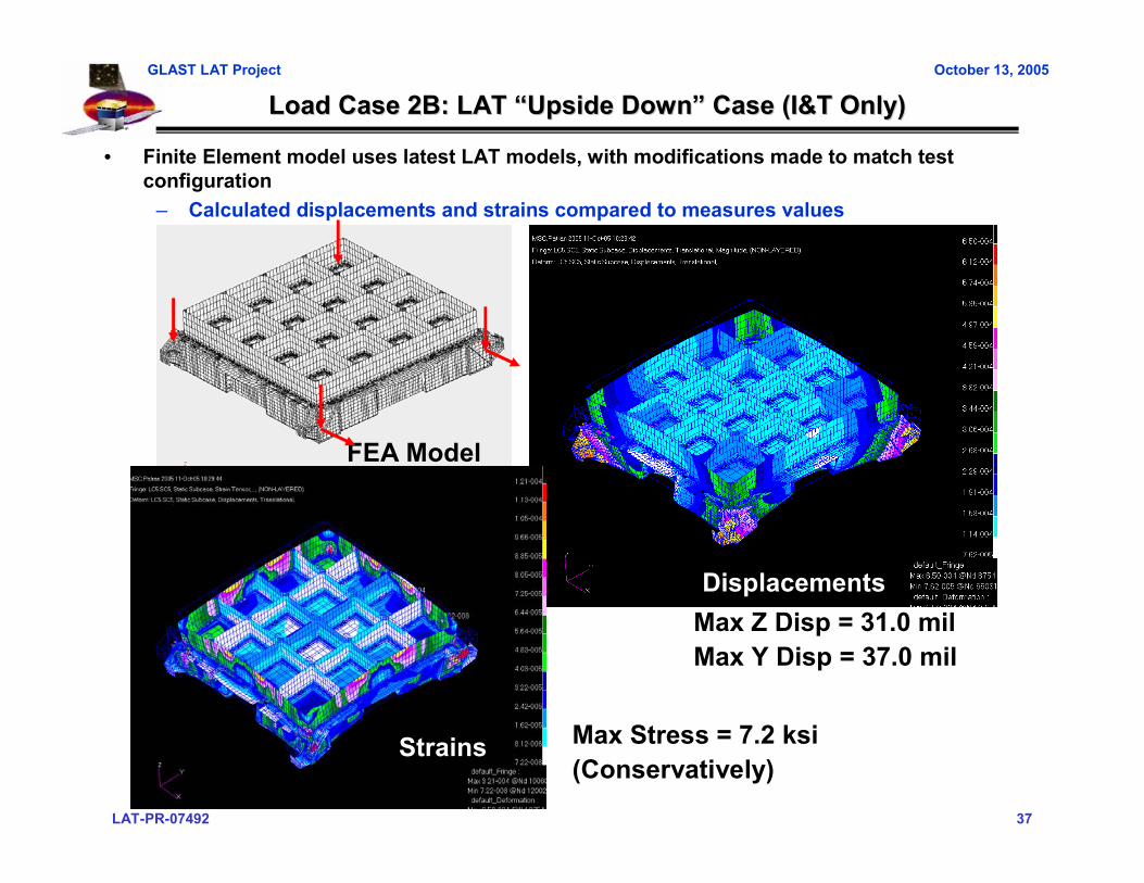
Load Case 2B: LAT Load Case 2B: LAT ““Upside DownUpside Down”” Case (I&T Only)Case (I&T Only)
• Finite Element model uses latest LAT models, with modifications made to match test configuration
– Calculated displacements and strains compared to measures values
Displacements
FEA Model
Max Z Disp = 31.0 milMax Y Disp = 37.0 mil
Max Stress = 7.2 ksi(Conservatively)
Strains

LAT-PR-07492 38
GLAST LAT Project October 13, 2005
Load Case 2B: LAT Load Case 2B: LAT ““Upside DownUpside Down”” Case (I&T Only)Case (I&T Only)
0% 20% 40% 60% 80% 90% 100% 90% 80% 60% 40% 20% 0%JP Predicted 0 -2290 -4580 -6870 -9160 -10305 -11450 -10305 -9160 -6870 -4580 -2290 0
MeasuredLVDT 1 Predicted
MeasuredLVDT 2 Predicted
MeasuredLVDT 3 Predicted
MeasuredLVDT 13 Predicted
Measured
• Zero instrumentation channels and verify they are functioning properly• Begin LC7A compression case by applying 40% load in the following increments:
– 0% 10% 20% 30% 40%– 40% 20% 0%
• If data is within 25% of predictions, continue to next step; else, sharpen pencil• Re-zero instrumentation channels and apply 100% load in the following increments:
– 0% 20% 40% 60% 80% 90% 100%– 100% 80% 60% 40% 20% 0%
• Without zeroing data, continue on to LC7B compression case:– 0% -20% -40% -60% -80% -90% -100%– -100% -80% -60% -40% -20% 0%
• Plot Load vs. Displacement and Load vs. Strain for all channels (should be closed loop)• Example Data Sheet Shown Below (pick critical channels to watch):
Fill in tables with LVDT and SG Predicts (TBD)Each LC will have its own Data Sheet
0% -20% -40% -60% -80% -90% -100% -90% -80% -60% -40% -20% 0%JP Predicted 0 1600 3200 4800 6400 7200 8000 7200 6400 4800 3200 1600 0
MeasuredLVDT 1 Predicted
MeasuredLVDT 2 Predicted
MeasuredLVDT 3 Predicted
MeasuredLVDT 13 Predicted
Measured

LAT-PR-07492 39
GLAST LAT Project October 13, 2005
Structural Test Predictions: LC1 and LC2 Inputs and Reactions Structural Test Predictions: LC1 and LC2 Inputs and Reactions
Load Jack Axis LC 1A LC 1B LC 1CJA Z -10900JB Z -10900JC Z -10900JD Z -10900JE Y 14200 14200 14200JF Z 7600JG Z 7600JH Z 7600JI Z 7600
Target Loads LC 1A LC 1B LC 1CY 7094 7094 7094
+X Z 10900 7600 0XX 3352 3352 3352
+Y Z 10900 7600 0Y 7094 7094 7094
-X Z 10900 7600 0XX 3352 3352 3352
-Y Z 10900 7600 0Reaction Loads LC 1A LC 1B LC 1C
Y 7059 7104 7082+X Z 10532 7972 382
XX 14846 15036 14958+Y Z 10904 7621 6
Y 7127 7082 7104-X Z 10536 7972 360
XX 14970 15229 15120-Y Z 11646 11646 742
Load Jack Axis LC 2A LC 2BJK1 Z 4100 -2600JK2 X 1650 1050JL Z 4100 -2600JM Z 4100 -2600JN1 Z 4100 -2600JN2 X 1650 1050
Target Loads LC 2A LC 2BX 1650 1050
+Y Z 4100 2600YY 0 0
+X Z 4100 2600X 1650 1050
-Y Z 4100 2600YY 0 0
-X Z 4100 2600Reaction Loads LC 2A LC 2B
X 1657 1045+Y Z 3683 2430
YY 3689 2174+X Z 4609 2716
X 1639 1052-Y Z 3680 2428
YY 3434 2281-X Z 4418 2828
• All SC mounts may not reach qual levels– Worst Case undertest = 3.4% (redundant load path)– Worst Case overtest = 53% (tension on flexure)
• F(u)=19364 lbf; FS=1.4; P=11646 lbf MS = 0.19
LAT-PR-07492 40
GLAST LAT Project October 13, 2005
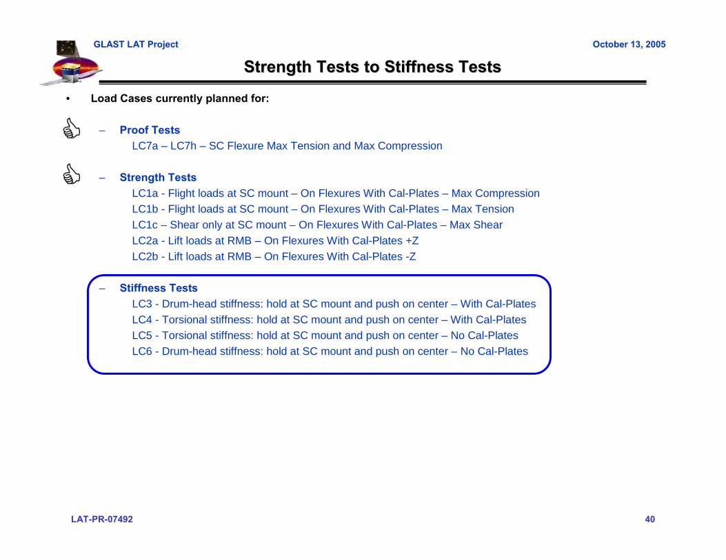
Strength Tests to Stiffness TestsStrength Tests to Stiffness Tests
• Load Cases currently planned for:
– Proof TestsLC7a – LC7h – SC Flexure Max Tension and Max Compression
– Strength TestsLC1a - Flight loads at SC mount – On Flexures With Cal-Plates – Max CompressionLC1b - Flight loads at SC mount – On Flexures With Cal-Plates – Max TensionLC1c – Shear only at SC mount – On Flexures With Cal-Plates – Max ShearLC2a - Lift loads at RMB – On Flexures With Cal-Plates +ZLC2b - Lift loads at RMB – On Flexures With Cal-Plates -Z
– Stiffness TestsLC3 - Drum-head stiffness: hold at SC mount and push on center – With Cal-PlatesLC4 - Torsional stiffness: hold at SC mount and push on center – With Cal-PlatesLC5 - Torsional stiffness: hold at SC mount and push on center – No Cal-PlatesLC6 - Drum-head stiffness: hold at SC mount and push on center – No Cal-Plates
LAT-PR-07492 41
GLAST LAT Project October 13, 2005
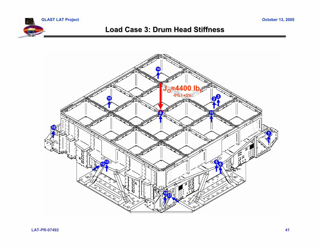
Load Case 3: Drum Head StiffnessLoad Case 3: Drum Head Stiffness
JO=4400 lbf-0% / +5%
13 5
2
18
1
3
6
10
15
16
17
19
12
8
LAT-PR-07492 42
GLAST LAT Project October 13, 2005
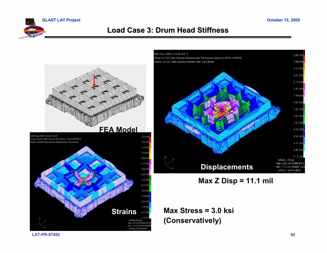
Load Case 3: Drum Head StiffnessLoad Case 3: Drum Head Stiffness
Displacements
FEA Model
Max Z Disp = 11.1 mil
Max Stress = 3.0 ksi(Conservatively)
Strains

LAT-PR-07492 43
GLAST LAT Project October 13, 2005
Load Case 3: Drum Head StiffnessLoad Case 3: Drum Head Stiffness
0% 20% 40% 60% 80% 90% 100% 90% 80% 60% 40% 20% 0%JP Predicted 0 -2290 -4580 -6870 -9160 -10305 -11450 -10305 -9160 -6870 -4580 -2290 0
MeasuredLVDT 1 Predicted
MeasuredLVDT 2 Predicted
MeasuredLVDT 3 Predicted
MeasuredLVDT 13 Predicted
Measured
• Zero instrumentation channels and verify they are functioning properly• Begin LC7A compression case by applying 40% load in the following increments:
– 0% 10% 20% 30% 40%– 40% 20% 0%
• If data is within 25% of predictions, continue to next step; else, sharpen pencil• Re-zero instrumentation channels and apply 100% load in the following increments:
– 0% 20% 40% 60% 80% 90% 100%– 100% 80% 60% 40% 20% 0%
• Without zeroing data, continue on to LC7B compression case:– 0% -20% -40% -60% -80% -90% -100%– -100% -80% -60% -40% -20% 0%
• Plot Load vs. Displacement and Load vs. Strain for all channels (should be closed loop)• Example Data Sheet Shown Below (pick critical channels to watch):
Fill in tables with LVDT and SG Predicts (TBD)Each LC will have its own Data Sheet
0% -20% -40% -60% -80% -90% -100% -90% -80% -60% -40% -20% 0%JP Predicted 0 1600 3200 4800 6400 7200 8000 7200 6400 4800 3200 1600 0
MeasuredLVDT 1 Predicted
MeasuredLVDT 2 Predicted
MeasuredLVDT 3 Predicted
MeasuredLVDT 13 Predicted
Measured

LAT-PR-07492 44
GLAST LAT Project October 13, 2005
Load Case 4: Torsional StiffnessLoad Case 4: Torsional Stiffness
JN=450 lbf-0% / +5%
13 5
2
1
3
6
10
15
16
17
19
12
8
18

LAT-PR-07492 45
GLAST LAT Project October 13, 2005
Load Case 4: Torsional StiffnessLoad Case 4: Torsional Stiffness
• Finite Element model uses latest LAT models, with modifications made to match test configuration
– Calculated displacements and strains compared to measures values
Displacements
FEA Model
Max Z Disp = 33.3 mil
Max Stress = 7.2 ksi(Conservatively)
Strains
LAT-PR-07492 46
GLAST LAT Project October 13, 2005
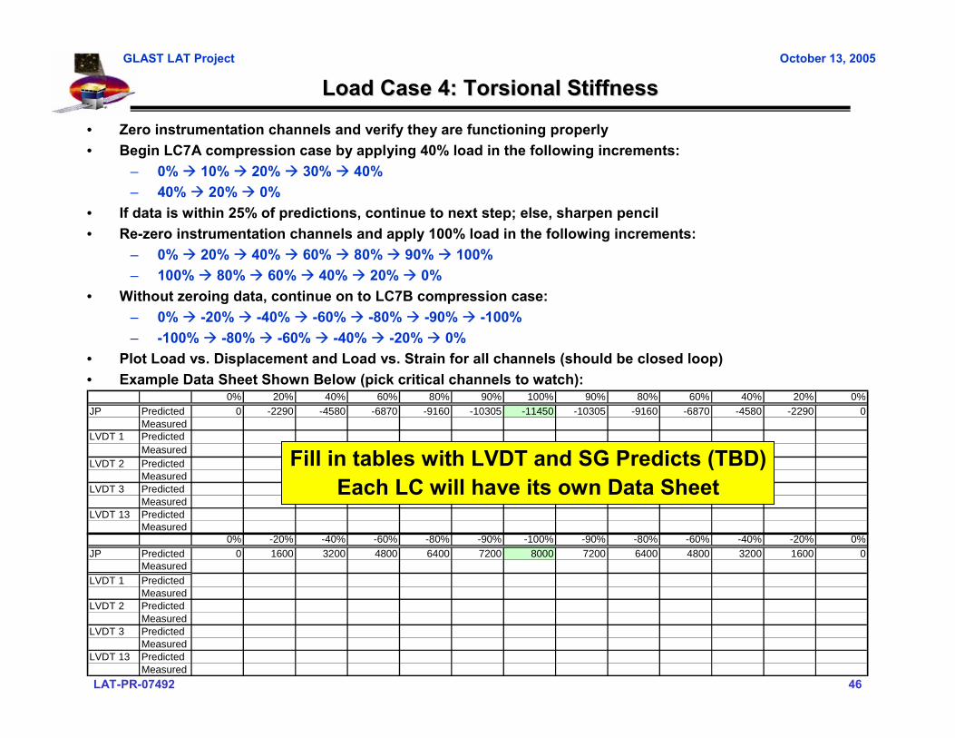
Load Case 4: Torsional StiffnessLoad Case 4: Torsional Stiffness
0% 20% 40% 60% 80% 90% 100% 90% 80% 60% 40% 20% 0%JP Predicted 0 -2290 -4580 -6870 -9160 -10305 -11450 -10305 -9160 -6870 -4580 -2290 0
MeasuredLVDT 1 Predicted
MeasuredLVDT 2 Predicted
MeasuredLVDT 3 Predicted
MeasuredLVDT 13 Predicted
Measured
• Zero instrumentation channels and verify they are functioning properly• Begin LC7A compression case by applying 40% load in the following increments:
– 0% 10% 20% 30% 40%– 40% 20% 0%
• If data is within 25% of predictions, continue to next step; else, sharpen pencil• Re-zero instrumentation channels and apply 100% load in the following increments:
– 0% 20% 40% 60% 80% 90% 100%– 100% 80% 60% 40% 20% 0%
• Without zeroing data, continue on to LC7B compression case:– 0% -20% -40% -60% -80% -90% -100%– -100% -80% -60% -40% -20% 0%
• Plot Load vs. Displacement and Load vs. Strain for all channels (should be closed loop)• Example Data Sheet Shown Below (pick critical channels to watch):
Fill in tables with LVDT and SG Predicts (TBD)Each LC will have its own Data Sheet
0% -20% -40% -60% -80% -90% -100% -90% -80% -60% -40% -20% 0%JP Predicted 0 1600 3200 4800 6400 7200 8000 7200 6400 4800 3200 1600 0
MeasuredLVDT 1 Predicted
MeasuredLVDT 2 Predicted
MeasuredLVDT 3 Predicted
MeasuredLVDT 13 Predicted
Measured

LAT-PR-07492 47
GLAST LAT Project October 13, 2005
Load Case 5: Torsional Stiffness without CAL platesLoad Case 5: Torsional Stiffness without CAL plates
JN=400 lbf-0% / +5%
Configuration Change:No CAL Plates
13 5
2
1
3
6
10
15
16
17
19
12
8
18

LAT-PR-07492 48
GLAST LAT Project October 13, 2005
Load Case 5: Torsional Stiffness without CAL platesLoad Case 5: Torsional Stiffness without CAL plates
• Finite Element model uses latest LAT models, with modifications made to match test configuration
– Calculated displacements and strains compared to measures values
Displacements
FEA Model
Max Z Disp = 34.2 mil
Max Stress = 1.2 ksi(Conservatively)
Strains

LAT-PR-07492 49
GLAST LAT Project October 13, 2005
Load Case 5: Torsional Stiffness without CAL platesLoad Case 5: Torsional Stiffness without CAL plates
0% 20% 40% 60% 80% 90% 100% 90% 80% 60% 40% 20% 0%JP Predicted 0 -2290 -4580 -6870 -9160 -10305 -11450 -10305 -9160 -6870 -4580 -2290 0
MeasuredLVDT 1 Predicted
MeasuredLVDT 2 Predicted
MeasuredLVDT 3 Predicted
MeasuredLVDT 13 Predicted
Measured
• Zero instrumentation channels and verify they are functioning properly• Begin LC7A compression case by applying 40% load in the following increments:
– 0% 10% 20% 30% 40%– 40% 20% 0%
• If data is within 25% of predictions, continue to next step; else, sharpen pencil• Re-zero instrumentation channels and apply 100% load in the following increments:
– 0% 20% 40% 60% 80% 90% 100%– 100% 80% 60% 40% 20% 0%
• Without zeroing data, continue on to LC7B compression case:– 0% -20% -40% -60% -80% -90% -100%– -100% -80% -60% -40% -20% 0%
• Plot Load vs. Displacement and Load vs. Strain for all channels (should be closed loop)• Example Data Sheet Shown Below (pick critical channels to watch):
Fill in tables with LVDT and SG Predicts (TBD)Each LC will have its own Data Sheet
0% -20% -40% -60% -80% -90% -100% -90% -80% -60% -40% -20% 0%JP Predicted 0 1600 3200 4800 6400 7200 8000 7200 6400 4800 3200 1600 0
MeasuredLVDT 1 Predicted
MeasuredLVDT 2 Predicted
MeasuredLVDT 3 Predicted
MeasuredLVDT 13 Predicted
Measured
LAT-PR-07492 50
GLAST LAT Project October 13, 2005
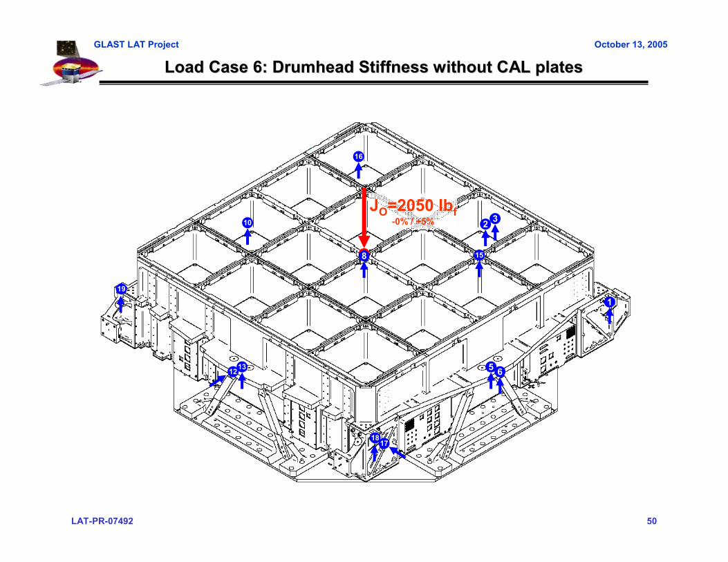
Load Case 6: Drumhead Stiffness without CAL platesLoad Case 6: Drumhead Stiffness without CAL plates
JO=2050 lbf-0% / +5%
13 5
2
18
1
3
6
10
15
16
17
19
12
8

LAT-PR-07492 51
GLAST LAT Project October 13, 2005
Load Case 6: Drumhead Stiffness without CAL platesLoad Case 6: Drumhead Stiffness without CAL plates
• Finite Element model uses latest LAT models, with modifications made to match test configuration
– Calculated displacements and strains compared to measures values
Displacements
FEA Model
Max Z Disp = 10.6 mil
Max Stress = 1.7 ksi(Conservatively)
Strains

LAT-PR-07492 52
GLAST LAT Project October 13, 2005
Load Case 6: Drumhead Stiffness without CAL platesLoad Case 6: Drumhead Stiffness without CAL plates
0% 20% 40% 60% 80% 90% 100% 90% 80% 60% 40% 20% 0%JP Predicted 0 -2290 -4580 -6870 -9160 -10305 -11450 -10305 -9160 -6870 -4580 -2290 0
MeasuredLVDT 1 Predicted
MeasuredLVDT 2 Predicted
MeasuredLVDT 3 Predicted
MeasuredLVDT 13 Predicted
Measured
• Zero instrumentation channels and verify they are functioning properly• Begin LC7A compression case by applying 40% load in the following increments:
– 0% 10% 20% 30% 40%– 40% 20% 0%
• If data is within 25% of predictions, continue to next step; else, sharpen pencil• Re-zero instrumentation channels and apply 100% load in the following increments:
– 0% 20% 40% 60% 80% 90% 100%– 100% 80% 60% 40% 20% 0%
• Without zeroing data, continue on to LC7B compression case:– 0% -20% -40% -60% -80% -90% -100%– -100% -80% -60% -40% -20% 0%
• Plot Load vs. Displacement and Load vs. Strain for all channels (should be closed loop)• Example Data Sheet Shown Below (pick critical channels to watch):
Fill in tables with LVDT and SG Predicts (TBD)Each LC will have its own Data Sheet
0% -20% -40% -60% -80% -90% -100% -90% -80% -60% -40% -20% 0%JP Predicted 0 1600 3200 4800 6400 7200 8000 7200 6400 4800 3200 1600 0
MeasuredLVDT 1 Predicted
MeasuredLVDT 2 Predicted
MeasuredLVDT 3 Predicted
MeasuredLVDT 13 Predicted
Measured

LAT-PR-07492 53
GLAST LAT Project October 13, 2005
Structural Test Margins of SafetyStructural Test Margins of Safety
Load Case Max Stress F (Y) FS (Y) MS (Y) F (U) FS (U) MS (U)[ksi] [ksi] [ksi]
1A 24.2 35 1.25 0.16 40 1.4 0.181B 18.7 35 1.25 0.50 40 1.4 0.531C 11.8 35 1.25 1.37 40 1.4 1.422A 10.5 35 1.25 1.67 40 1.4 1.722B 7.2 35 1.25 2.89 40 1.4 2.973 3 35 1.25 8.33 40 1.4 8.524 7.2 35 1.25 2.89 40 1.4 2.975 1.2 35 1.25 22.33 40 1.4 22.816 1.7 35 1.25 15.47 40 1.4 15.81
LAT-PR-07492 54
GLAST LAT Project October 13, 2005
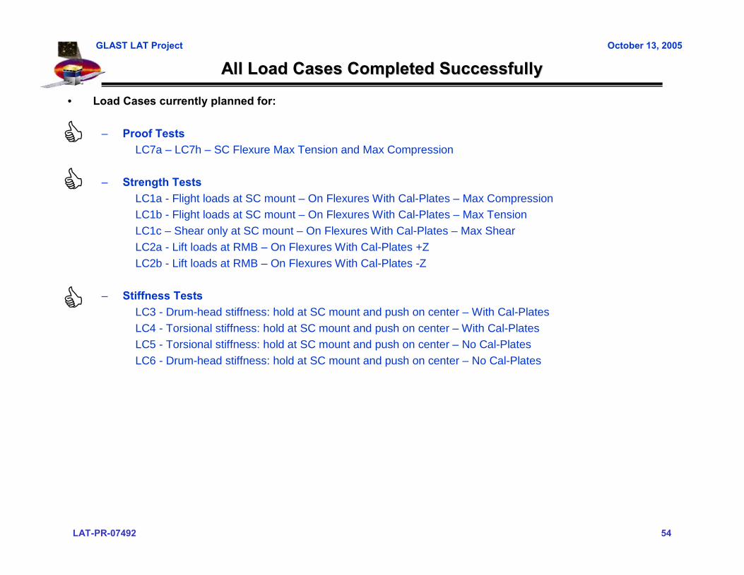
All Load Cases Completed SuccessfullyAll Load Cases Completed Successfully
• Load Cases currently planned for:
– Proof TestsLC7a – LC7h – SC Flexure Max Tension and Max Compression
– Strength TestsLC1a - Flight loads at SC mount – On Flexures With Cal-Plates – Max CompressionLC1b - Flight loads at SC mount – On Flexures With Cal-Plates – Max TensionLC1c – Shear only at SC mount – On Flexures With Cal-Plates – Max ShearLC2a - Lift loads at RMB – On Flexures With Cal-Plates +ZLC2b - Lift loads at RMB – On Flexures With Cal-Plates -Z
– Stiffness TestsLC3 - Drum-head stiffness: hold at SC mount and push on center – With Cal-PlatesLC4 - Torsional stiffness: hold at SC mount and push on center – With Cal-PlatesLC5 - Torsional stiffness: hold at SC mount and push on center – No Cal-PlatesLC6 - Drum-head stiffness: hold at SC mount and push on center – No Cal-Plates
LAT-PR-07492 55
GLAST LAT Project October 13, 2005
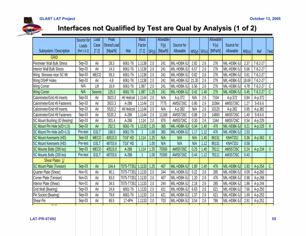
Interfaces not Qualified by Test are Qual by Analysis (1 of 2)Interfaces not Qualified by Test are Qual by Analysis (1 of 2)
Subsystem / Description
Source for Loads
[Ref 1 & 2]
Load Case [7.2]
Peak Stress/Load
[Mpa/N] Mat
Mass Factor [7.1] SF(y)
Alowable F(y)
[Mpa/N]Source for Allowable MS(y) SF(u)
Allowable F(u)
[MPa/N]Source for Allowable MS(u) Ref Test
GRIDPerimeter Wall Bulk Stress Sep-03 Air 28.3 6061-T6 1.1138 2.0 241 MIL-HDBK-5J 2.82 2.6 276 MIL-HDBK-5J 2.37 T-8.2-27Interior Wall Bulk Stress Sep-03 Air 14.3 6061-T6 1.1138 2.0 241 MIL-HDBK-5J 6.57 2.6 276 MIL-HDBK-5J 5.66 T-8.2-27Wing Stresses near SC Mt Sep-03 MECO 59.3 6061-T6 1.1138 2.0 241 MIL-HDBK-5J 0.82 2.6 276 MIL-HDBK-5J 0.61 T-8.2-27Wing DSHP Holes Sep-03 Air 4.8 6061-T6 1.1138 2.0 241 MIL-HDBK-5J 21.35 2.6 276 MIL-HDBK-5J 18.69 T-8.2-27Wing Corner N/A Lift 16.9 6061-T6 1.087 2.0 241 MIL-HDBK-5J 5.56 2.6 276 MIL-HDBK-5J 4.78 T-8.2-27 CWing Corner N/A Seismic 125.0 6061-T6 1.087 1.25 241 MIL-HDBK-5J 0.42 1.40 276 MIL-HDBK-5J 0.45 T-8.2-27 CCalorimeter/Grid #6 Inserts Sep-03 Air 3923.3 #6 Helicoil 1.1144 2.0 N/A A-p.372 N/A 2.6 7104 A-p.372 0.84 A-p.372Calorimeter/Grid #6 Fasteners Sep-03 Air 3923.3 A-286 1.1144 2.0 7775 AMS5726C 0.80 2.6 10364 AMS5726C 1.27 S-8.6.6Calorimeter/Grid #8 Inserts Sep-03 Air 5520.2 #8 Helicoil 1.1144 2.0 N/A A-p.382 N/A 2.6 10120 A-p.382 0.95 A-p.382Calorimeter/Grid #8 Fasteners Sep-03 Air 5520.2 A-286 1.1144 2.0 11169 AMS5726C 0.88 2.6 14893 AMS5726C 1.40 S-8.6.6SC Mount Bushing (ID Bearing) Sep-03 Air 301.4 A-286 1.114 2.0 876 AMS5726C 0.30 2.6 1344 AMS5726C 0.54 A-p.229SC Mount Pin Hole (e/D=1.5) Sep-03 Air 252.3 6061-T6 1.1133 1.25 365 MIL-HDBK-5J 0.04 1.40 476 MIL-HDBK-5J 0.21 A-p.229 XSC Mount Pin Hole (e/D=1.5) Pre-test GSLT 168.0 6061-T6 1 1.00 365 MIL-HDBK-5J 1.17 1.12 476 MIL-HDBK-5J 1.53SC Mount Keenserts (HD) Sep-03 MECO 40515.0 7/16" HD 1.114 1.25 N/A N/A N/A 1.40 86131 KNH720J 0.36 A-p.363 XSC Mount Keenserts (HD) Pre-test GSLT 48703.6 7/16" HD 1 1.00 N/A N/A N/A 1.12 86131 KNH720J 0.58SC Mounts Bolts (200 ksi) Sep-03 MECO 40515.0 A-286 1.114 1.25 70300 AMS5726C 0.25 1.40 78111 AMS5726C 0.24 A-p.234 XSC Mounts Bolts (200 ksi) Pre-test GSLT 48703.6 A-286 1 1.00 70300 AMS5726C 0.44 1.12 78111 AMS5726C 0.43
Shear Plates 1/SC Mount Plate (Tension) Sep-03 Air 104.4 7075-T7351 1.1133 1.25 407 MIL-HDBK-5J 1.80 1.40 476 MIL-HDBK-5J 1.93 A-p.254 CQuarter Plate (Shear) Nov-01 Air 90.1 7075-T7351 1.1133 2.0 244 MIL-HDBK-5J 0.22 2.6 285 MIL-HDBK-5J 0.09 A-p.260Corner Plate (Tension) Nov-01 Air 83.0 7075-T7351 1.1133 2.0 407 MIL-HDBK-5J 1.20 2.6 476 MIL-HDBK-5J 0.98 A-p.268Interior Plate (Shear) Nov-01 Air 34.5 7075-T7351 1.1133 2.0 244 MIL-HDBK-5J 2.18 2.6 285 MIL-HDBK-5J 1.86 A-p.244Grid Wall (Bearing) Sep-03 Air 24.8 6061-T6 1.1133 2.0 421 MIL-HDBK-5J 6.63 2.6 621 MIL-HDBK-5J 7.66 A-p.250Pin Socket (Bearing) Sep-03 Air 79.8 6061-T6 1.1133 2.0 421 MIL-HDBK-5J 1.37 2.6 621 MIL-HDBK-5J 1.69 A-p.253Shear Pin Sep-03 Air 69.5 17-4PH 1.1133 2.0 703 MIL-HDBK-5J 3.54 2.6 786 MIL-HDBK-5J 2.91 A-p.251
TKR

LAT-PR-07492 56
GLAST LAT Project October 13, 2005
Interfaces not Qualified by Test are Qual by Analysis (2 of 2)Interfaces not Qualified by Test are Qual by Analysis (2 of 2)
TKRTop Flange Twist (Bending) Nov-01 Air 22.0 6061-T6 1.1133 2.0 241 MIL-HDBK-5J 3.92 2.6 476 MIL-HDBK-5J 6.47 S-8.2.2.3Shoulder Bolt Joint GEVS Random 3241.0 A-286 1.114 2.0 11135 AMS5732H 0.54 2.6 17026 AMS5732H 0.81 A-p.297 SSGrid Wall (Bearing) GEVS Random 4051.3 6061-T6 1.1133 2.0 15700 Bruhn-D1.7 0.74 2.6 13008 Bruhn-D1.8 0.11 A-p.278 SS
ACDMid-side Pin (3/8") Nov-01 MECO 22.6 A-286 1.114 2.0 144.6 0.6* Fty 1.88 2.6 285.6 0.6 * Ftu 3.37 S-8.6.4ACD Inserts (3/8") Nov-01 Air 276.5 Helicoil 1.114 2.0 1100 Vendor DS 0.79 2.6 1240 Vendor DS 0.55 S-8.6.4Mid-side Bolts (3/8") Nov-01 Air 276.5 A-286 1.114 2.0 1100 AMS5732H 0.79 2.6 1240 AMS5732H 0.55 S-8.6.4Corner Bolts (1/4") Nov-01 Air 276.5 A-286 1.114 2.0 733 AMS5732H 0.19 2.6 827 AMS5732H 0.03 S-8.6.4
RMBBulk Stresses Nov-01 Lift 170.5 6061-T6 1.1144 1.25 241 MIL-HDBK-5J 0.01 1.40 276 MIL-HDBK-5J 0.04 T-8.4-46 XBulk Stresses Pre-test GSLT 31.9 6061-T6 1 1.00 241 MIL-HDBK-5J 6.55 1.12 276 MIL-HDBK-5J 6.73RMB/RAD Pin Socket (Bearing) Nov-01 MECO 293.4 6061-T6 1.1144 1.25 421 MIL-HDBK-5J 0.03 1.40 621 MIL-HDBK-5J 0.36 F-8.4-47 XRMB/RAD Pin Socket (Bearing) Pre-test GSLT 408.7 6061-T6 1 1.00 421 MIL-HDBK-5J 0.03 1.12 621 MIL-HDBK-5J 0.36RMB Inserts N/A EQ 184.6 Helicoil 1.114 2.0 590 Vendor DS 0.43 2.6 900 Vendor DS 0.68 F-8.6-61RMB Bolts N/A EQ 184.6 A-286 1.114 2.0 590 AMS5732H 0.43 2.6 900 AMS5732H 0.68 F-8.6-61Lifting Clevis (Tension) N/A EQ 86.0 6061-T6 1.1144 2.0 241 MIL-HDBK-5J 0.26 2.6 276 MIL-HDBK-5J 0.11 F-8.4-48 C
EMI SkirtsBulk Stresses Nov-01 Lift 47.9 6061-T6 1.1138 2.0 241 MIL-HDBK-5J 1.26 2.6 276 MIL-HDBK-5J 0.99 T-8.3-39EMI Inserts (1/4") Nov-01 Lift 324.7 Helicoil 1.114 2.0 1100 Vendor DS 0.52 2.6 1240 Vendor DS 0.32 S-8.6.3EMI Skirt Fasteners (1/4") Nov-01 Lift 324.7 A-286 1.114 2.0 1100 AMS5732H 0.52 2.6 1240 AMS5732H 0.32 S-8.6.3
X-LAT PlateSubstrate Sep-03 Lift 67.7 6061-T6 1.1133 2.0 241 MIL-HDBK-5J 0.60 2.6 276 MIL-HDBK-5J 0.41 S-8.5.2Pocket Stresses Sep-03 Air 67.7 6061-T6 1.1133 2.0 241 MIL-HDBK-5J 0.60 2.6 276 MIL-HDBK-5J 0.41 S-8.5.2Heat Pipes Sep-03 Air 38.7 6061-T6 1.1133 2.0 241 MIL-HDBK-5J 1.80 2.6 276 MIL-HDBK-5J 1.46 S-8.5.2X-LAT #8 Fasteners (shear out) Sep-03 Lift 112.3 6061-T6 1.1133 2.0 365 MIL-HDBK-5J 0.46 2.6 476 MIL-HDBK-5J 0.46 A-p.342
NOTES:1/ Shear loads at Calorimeter tabs previously analyzed2/ Test Required; does not meet GEVS QBA: C=Coupon; X=GSLT; SS=Subsystem3/ Test Safety factor built into stress calculation
Subsystem / Description
Source for Loads
[Ref 1 & 2]
Load Case [7.2]
Peak Stress/Load
[Mpa/N] Mat
Mass Factor [7.1] SF(y)
Alowable F(y)
[Mpa/N]Source for Allowable MS(y) SF(u)
Allowable F(u)
[MPa/N]Source for Allowable MS(u) Ref Test
LAT-PR-07492 57
GLAST LAT Project October 13, 2005
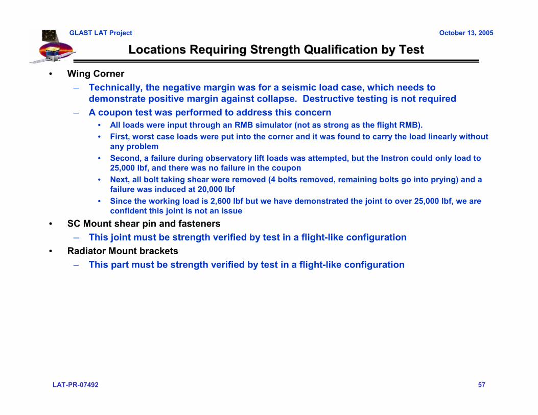
Locations Requiring Strength Qualification by TestLocations Requiring Strength Qualification by Test
• Wing Corner– Technically, the negative margin was for a seismic load case, which needs to
demonstrate positive margin against collapse. Destructive testing is not required– A coupon test was performed to address this concern
• All loads were input through an RMB simulator (not as strong as the flight RMB).• First, worst case loads were put into the corner and it was found to carry the load linearly without
any problem• Second, a failure during observatory lift loads was attempted, but the Instron could only load to
25,000 lbf, and there was no failure in the coupon• Next, all bolt taking shear were removed (4 bolts removed, remaining bolts go into prying) and a
failure was induced at 20,000 lbf• Since the working load is 2,600 lbf but we have demonstrated the joint to over 25,000 lbf, we are
confident this joint is not an issue• SC Mount shear pin and fasteners
– This joint must be strength verified by test in a flight-like configuration• Radiator Mount brackets
– This part must be strength verified by test in a flight-like configuration

LAT-PR-07492 58
GLAST LAT Project October 13, 2005
Other Tests Performed giving confidence in the analysisOther Tests Performed giving confidence in the analysis
• 1x4 Stiffness Test– Stiffness results were good with and without the calorimeter plates
• Shear plate coupon test (at SC mount)– Meets no-test criteria, but as a primary load path, we wanted to verify the strength by test
• The plate itself and keys/keyways functioned flawlessly• The liquid shim performed as expected
• TKR to Grid interface– Meets no-test criteria, but with previous failures and high random loads, it was desired to
incorporate flight grid features, i.e. minimum edge distances and flight like fasteners and installation procedure
• RMB Lift Clevis– As part of the wing corner test, the clevis has been strength verified

LAT-PR-07492 59
GLAST LAT Project October 13, 2005
ConclusionsConclusions
• Pre-test analysis complete– Differences in Grid #2 and the flight grid are accounted for in the pre-test analysis– Displacement predictions complete integrated LAT model will be validated if the
predicted displacements are within 15% of measured values– Stress analyses of all test configurations and load cases (with additional safety factor
added) show positive margins
• Areas of mechanical subsystem not verified by this test were either previously qualified by flight-like coupon test or by analysis
• Successful conclusion of the Grid #2 Static Load Test will qualify the flight grid design for all mechanical environments, including loads imparted during AI&T, Transport, Ascent, and on-orbit operation

LAT-PR-07492 60
GLAST LAT Project October 13, 2005
Mechanical Systems
Grid #2 Static Load TestTest Readiness Review
Test Set Up
Mechanical SystemsMechanical Systems
Grid #2 Static Load TestGrid #2 Static Load TestTest Readiness ReviewTest Readiness Review
Test Set UpTest Set Up
Marc Campell [email protected] Campell [email protected]
LAT-PR-07492 61
GLAST LAT Project October 13, 2005
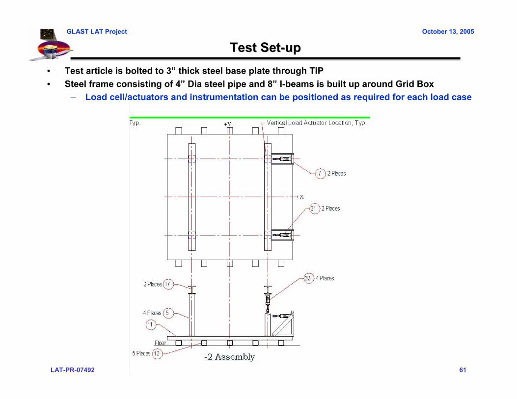
Test SetTest Set--upup• Test article is bolted to 3” thick steel base plate through TIP• Steel frame consisting of 4” Dia steel pipe and 8” I-beams is built up around Grid Box
– Load cell/actuators and instrumentation can be positioned as required for each load case
LAT-PR-07492 62
GLAST LAT Project October 13, 2005
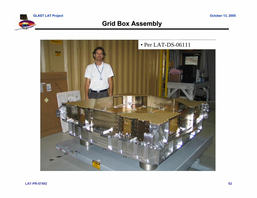
Grid Box AssemblyGrid Box Assembly
• Per LAT-DS-06111
LAT-PR-07492 63
GLAST LAT Project October 13, 2005
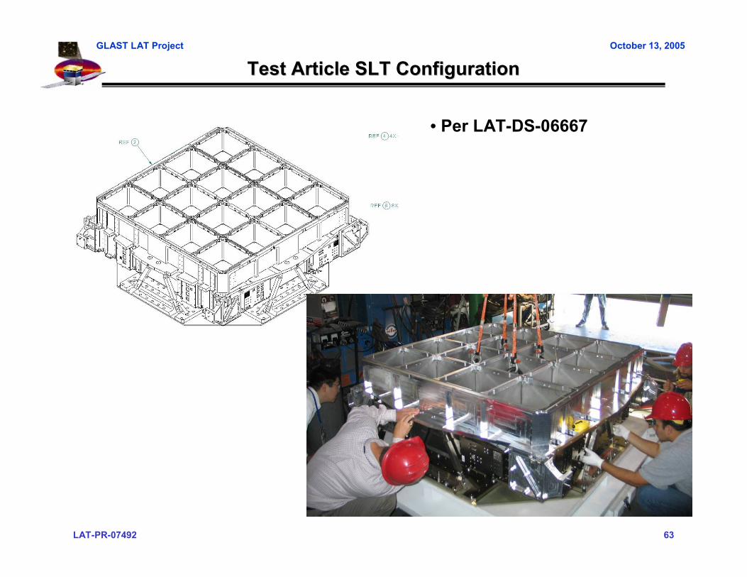
Test Article SLT ConfigurationTest Article SLT Configuration
• Per LAT-DS-06667

LAT-PR-07492 64
GLAST LAT Project October 13, 2005
Flexure Test Set upFlexure Test Set up• Per LAT-DS-06667

LAT-PR-07492 65
GLAST LAT Project October 13, 2005
Hardware Differences from FlightHardware Differences from Flight
• All hardware built to flight drawings with the exceptions shown on the following charts
– Grid– Grid Box– Spacecraft interface

LAT-PR-07492 66
GLAST LAT Project October 13, 2005
Deviations from Flight GridDeviations from Flight Grid
• Eliminate all cable chaseways from the sidewalls, shown on sheet 8. The cable cutouts in the +Z top flange will remain.
– Strain gage placed in this region to demonstrate that this area is lowly loaded• Eliminate 4-40 tapped thermal strap holes and .062" dia vent holes from the +Z top
flange shown on SH 8.
LAT-PR-07492 67
GLAST LAT Project October 13, 2005
Deviations from Flight GridDeviations from Flight Grid
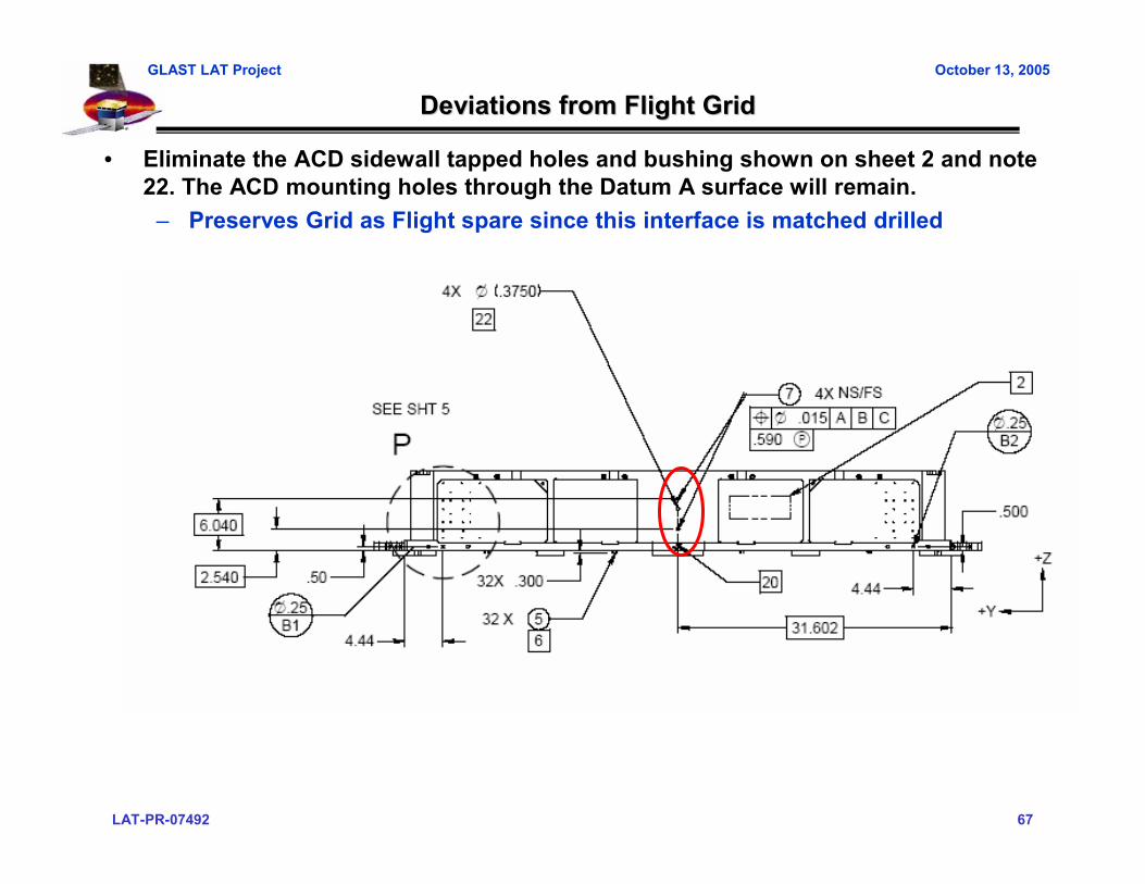
• Eliminate the ACD sidewall tapped holes and bushing shown on sheet 2 and note 22. The ACD mounting holes through the Datum A surface will remain.
– Preserves Grid as Flight spare since this interface is matched drilled
LAT-PR-07492 68
GLAST LAT Project October 13, 2005
Deviations from Flight GridDeviations from Flight Grid
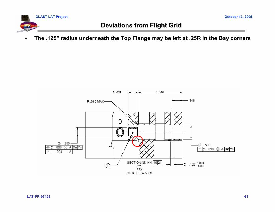
• The .125" radius underneath the Top Flange may be left at .25R in the Bay corners
LAT-PR-07492 69
GLAST LAT Project October 13, 2005
Deviations From Flight GridDeviations From Flight Grid
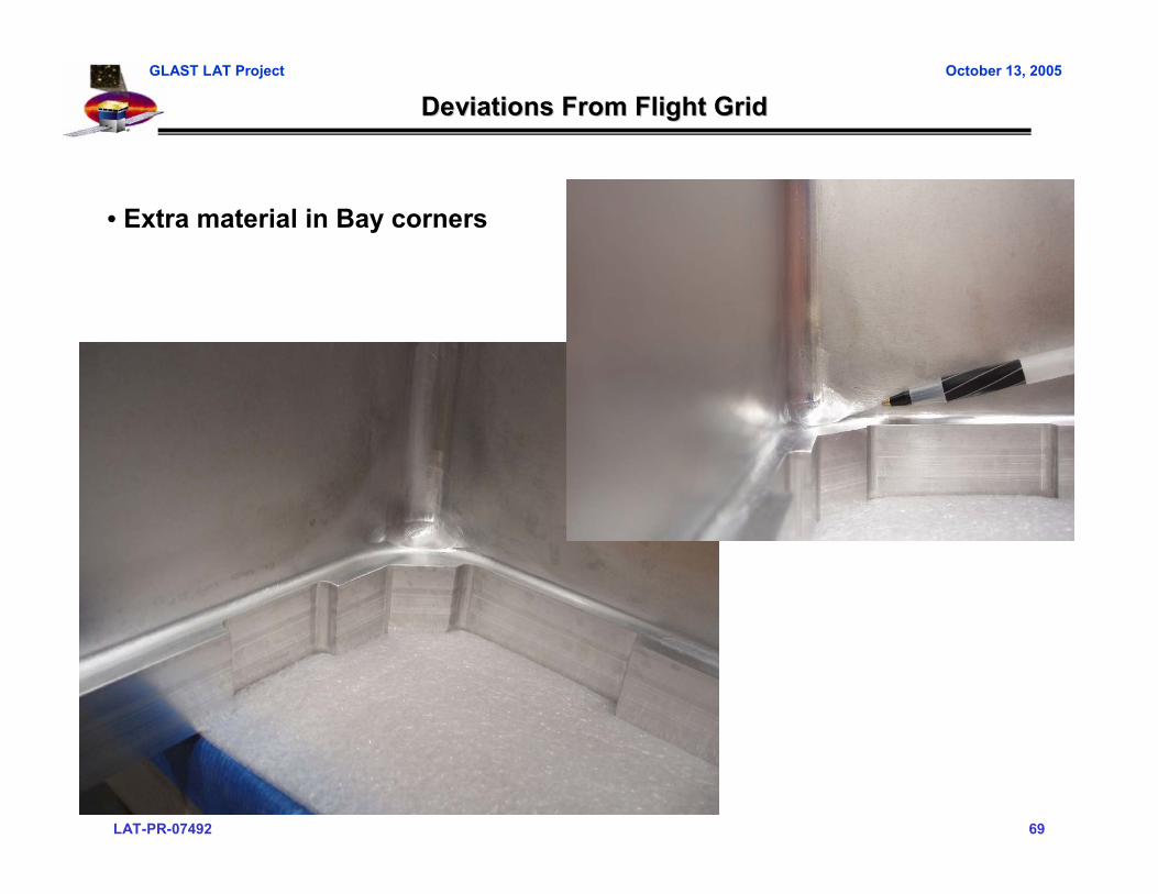
• Extra material in Bay corners

LAT-PR-07492 70
GLAST LAT Project October 13, 2005
Deviations from Flight GridDeviations from Flight Grid
• Eliminate the alodine and Nickel plating requirements (notes 11 and 15).
LAT-PR-07492 71
GLAST LAT Project October 13, 2005
Deviations from Flight GridDeviations from Flight Grid
• Tracker interface holes in all bays, but bushing only put in 4 of 16 Bays

LAT-PR-07492 72
GLAST LAT Project October 13, 2005
Deviations from Flight Grid BoxDeviations from Flight Grid Box
• Dummy CAL Baseplates simulate in plane stiffness– Tabs are flight like (for out of plane stiffness)– Material is 6061-T6 vs. 7075-T7351– Finish is alodine vs. electroless Nickel

LAT-PR-07492 73
GLAST LAT Project October 13, 2005
Deviations from Flight Grid BoxDeviations from Flight Grid Box
• Nuts used on CAL shear plates are commercial locking nut vs Nitronic 60– Galling observed with original flight design– Replacing nuts now would remove compressive load from liquid shim joint
around CAL stud
X-LAT Dummy ¼ panel
CAL studs
LAT-PR-07492 74
GLAST LAT Project October 13, 2005
Deviations from Flight Grid BoxDeviations from Flight Grid Box
• X-LAT Plate replaced with dummy quarter panels– Allows access for instrumentation– Quarter panels tie EMI shields and Radiator Mount Brackets together; shear
tie• EMI gaskets not installed on EMI shields• Commercial grade 8 fasteners used for some Doghouse panel and Wing close out
bar attachment
LAT-PR-07492 75
GLAST LAT Project October 13, 2005
Deviations from Flight GridDeviations from Flight Grid--Spacecraft InterfaceSpacecraft Interface
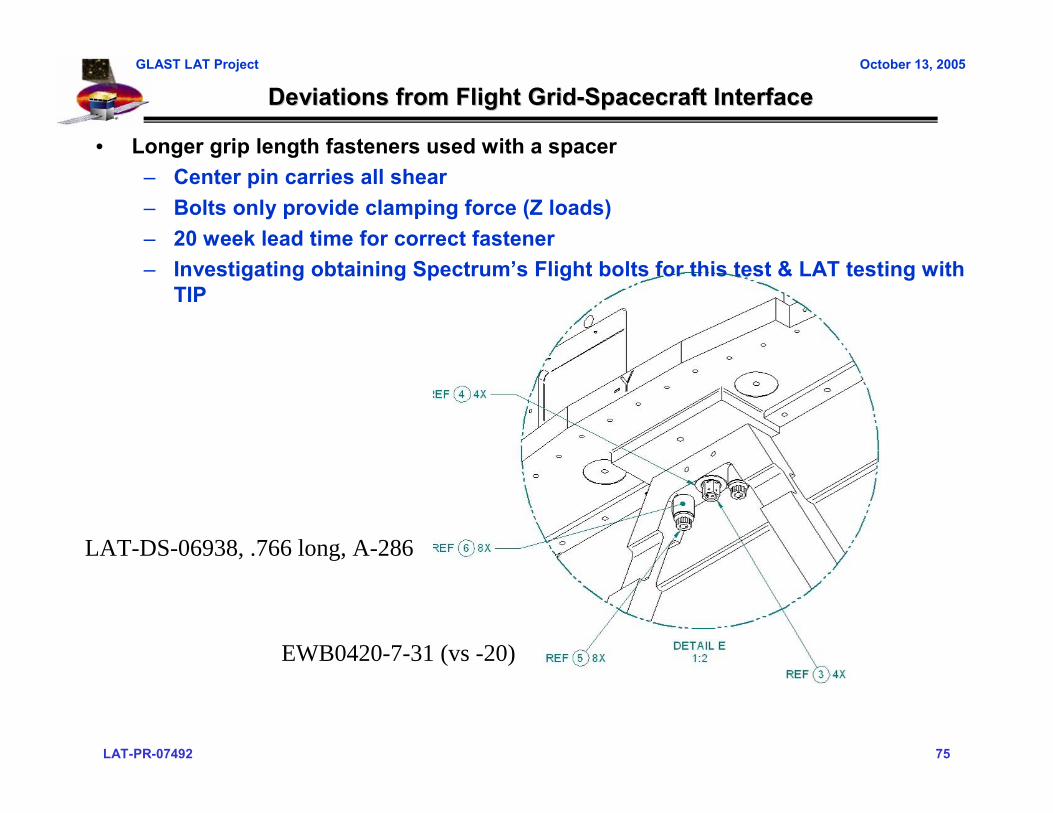
• Longer grip length fasteners used with a spacer– Center pin carries all shear– Bolts only provide clamping force (Z loads)– 20 week lead time for correct fastener– Investigating obtaining Spectrum’s Flight bolts for this test & LAT testing with
TIP
LAT-DS-06938, .766 long, A-286
EWB0420-7-31 (vs -20)

LAT-PR-07492 76
GLAST LAT Project October 13, 2005
Mechanical Systems
Grid #2 Static Load TestTest Readiness Review
Test Facilities
Mechanical SystemsMechanical Systems
Grid #2 Static Load TestGrid #2 Static Load TestTest Readiness ReviewTest Readiness Review
Test FacilitiesTest Facilities
Mike Springer [email protected] LeBlanc [email protected]
Mike Springer [email protected] LeBlanc [email protected]
LAT-PR-07492 77
GLAST LAT Project October 13, 2005
Test FacilitiesTest Facilities
• NTS Overview– NTS has been in the testing business since 1961– NTS is a publicly owned corporation (NASDAQ: NTSC)– NTS is a full service provider of Aerospace and Defense oriented testing
services. NTS performs a variety of tests in the following areas:• Environmental• Climatics• Dynamics• Structural• EMI/EMC

LAT-PR-07492 78
GLAST LAT Project October 13, 2005
NTS Key PersonnelNTS Key Personnel• Mike Springer, Program Manager
– Seven years experience in Environmental Testing, – Three years in Program Management
• John Gavagnini, Engineering Department Manager– Twenty years experience in Environmental Testing and
Engineering• Pat Le Blanc, PhD, Instrumentation Department Manager
– Twenty years experience in Testing and Test Instrumentation Design and Implementation
• Art Edelstein, Technical Consultant– Forty years experience in Testing and Test System Design
including complex load test systems• Ron Bocksruker, Mechanical Design
– Forty years experience in Structural Design and Mechanical System Design
• Damien Costello, Lead Hydraulics Technician– Forty years experience in Hydraulic System Set-up and Operation
• Sergey Klochko, Instrumentation Engineer– Nine years Instrumentation experience
• Tim Kogen, Instrumentation Technician– Four years Instrumentation experience
LAT-PR-07492 79
GLAST LAT Project October 13, 2005
Load Application System & SafeguardsLoad Application System & Safeguards
• Cyber FM 7000 Digital Load Control System• Initial Ramp Steps: 10, 20, 30, 40% Full Load, then return• Test Ramp Steps: 20, 40, 60, 80, 90, 100% Full Load, then return• Discretionary pause at each load step to verify response.• Servo control modules configured with Error Limits and Load Limits.• Test shutdown if Feedback Error > Error Limit (typ. 5% Full Load)• Test Shutdown if Feedback Load > Load Limit (typ. 105% Full Load).• Test Shutdown Action: Remove Hydraulic Pressure• Operator Shutdown buttons in Control Room and Test Hardware Area• Servo valves configured with a relief pressure bypass as an independent limit for
the maximum load on each actuator.

LAT-PR-07492 80
GLAST LAT Project October 13, 2005
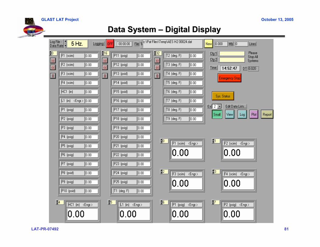
Data AcquisionData Acquision
• Independent LabView data acquisition system• Spreadsheet formatted text data recorded at 1 Hz.• Separate “Remote Viewer” computer(s) available for SLAC to Real-Time monitor
of test channels – Independent from the test operator console.– Digital and Plot data Display– Plot configurable with Time or Load X-Axis
• LabView based Plot utility for post test review of strain and displacement vs. load.– Software executable copy available to SLAC
LAT-PR-07492 81
GLAST LAT Project October 13, 2005
Data System Data System –– Digital DisplayDigital Display

LAT-PR-07492 82
GLAST LAT Project October 13, 2005
Data System Data System –– Real Time PlotReal Time Plot
LAT-PR-07492 83
GLAST LAT Project October 13, 2005
System ValidationSystem Validation
• Load Application System– Full system checkout (actuator control with feedback channel) on each
actuator in an independent fixture – prior to assembly into test hardware
• Data Acquision System– End-to-end signal verification for Load and Displacement Channels– R-Cal scaling and verification of Strain Channels– Re-Zero All channels Prior to each Test
LAT-PR-07492 84
GLAST LAT Project October 13, 2005
QA SystemQA System
• NTS Quality Assurance System Complies with the following standards and specifications:
– ISO 17025– ISO/IES Guide 25– FAA-STD-016– ISO 9000– ISO 9002– ISO 10012– ISO 10012-1– MIL-I-45208A– MIL-STD-45662A– MIL-Q-9858A
LAT-PR-07492 85
GLAST LAT Project October 13, 2005
CalibrationsCalibrations
• The following hardware has current calibrations – 11 Load Cells:
(Due back from Cal vendor - week of 10/10)– 16 LVDT’s:
(to be calibrated at NTS, using precision gage block standards calibrated 5/26/2005)
– Data Acquisition card and Amplifier modules: (Due back from Cal vendor - week of 10/10)
• Calibration Vendors accredited to ISO 17025

LAT-PR-07492 86
GLAST LAT Project October 13, 2005
SafetySafety• Hardware safety
– Will be defined in the final procedure
• Personnel Safety– Per NTS Operating Procedures– Details will be provided at Delta TRR
LAT-PR-07492 87
GLAST LAT Project October 13, 2005
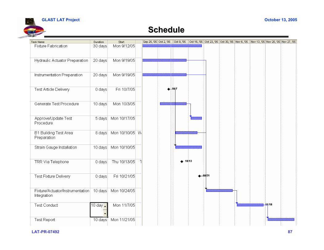
ScheduleSchedule
LAT-PR-07492 88
GLAST LAT Project October 13, 2005
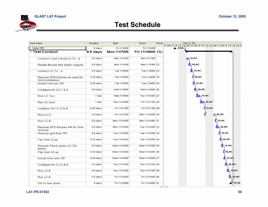
Test ScheduleTest Schedule

LAT-PR-07492 89
GLAST LAT Project October 13, 2005
NTS StatusNTS Status
All instrumentation, equipment and fixtures have been ordered• Outstanding orders & Due Date
– Base Plate 10/21– Flexure Beam Support 10/14– Loading Blocks 10/14
• Draft procedure out for review 10/11– Release due 10/21
• Test site preparation– Area cleared & cleaned by 10/21– Erect tent by 10/28
Test article received from SLAC 10/7• Strain gage installation started

LAT-PR-07492 90
GLAST LAT Project October 13, 2005
Load Fixture ValidationLoad Fixture Validation
• Actuator capacity is x times greater than applied loads• Fixtures attaching to test article are validated by analysis
– 12630-103 Loading Block, Flexures MS=– 12630-104 Loading Block, Center MS=– 12630-105 Loading Block, Corner Brkt MS=– 12630-106 Loading Block, S/C Interface MS= 6.4– 12630-107 Flexure Beam & Support, SLAC provided design
• Prevents buckling of flexures during flexure only testing• MS= John to provide
LAT-PR-07492 91
GLAST LAT Project October 13, 2005
Test ReportTest Report
• Test report provided 2 weeks after completion of test• Report contents
– Summary of testing– Plots of displacement and strain versus load– Photos of test set-up for each load case– Test logs
LAT-PR-07492 92
GLAST LAT Project October 13, 2005
Test Readiness Review
Quality Assurance
Test Readiness Review
Quality AssuranceQuality Assurance
Joe Cullinan [email protected] Cullinan [email protected]

LAT-PR-07492 93
GLAST LAT Project October 13, 2005
Quality Assurance Plan for Grid Static Load TestQuality Assurance Plan for Grid Static Load Test
• Approve vendor’s quality system, process control and documentation • Review and approve vendor’s test plan• SLAC/LAT QA and Mechanical Systems to witness static load test• Verify test, measurement and inspection data meets LAT program
requirements• Ensure non-conformances are documented and resolved• Review, approve and retain final test data package• Photo documentation
• Test fixtures and test configurations of Grid• Any discrepancy or nonconformance with fixtures or Grid
• Support post-test review and return shipment of Grid to SLAC

LAT-PR-07492 94
GLAST LAT Project October 13, 2005
Mechanical Systems
Grid #2 Static Load TestTest Readiness Review
Open Items/Conclusions
Mechanical SystemsMechanical Systems
Grid #2 Static Load TestGrid #2 Static Load TestTest Readiness ReviewTest Readiness Review
Open Items/ConclusionsOpen Items/Conclusions
Marc Campell [email protected] Campell [email protected]
LAT-PR-07492 95
GLAST LAT Project October 13, 2005
Open Items Open Items
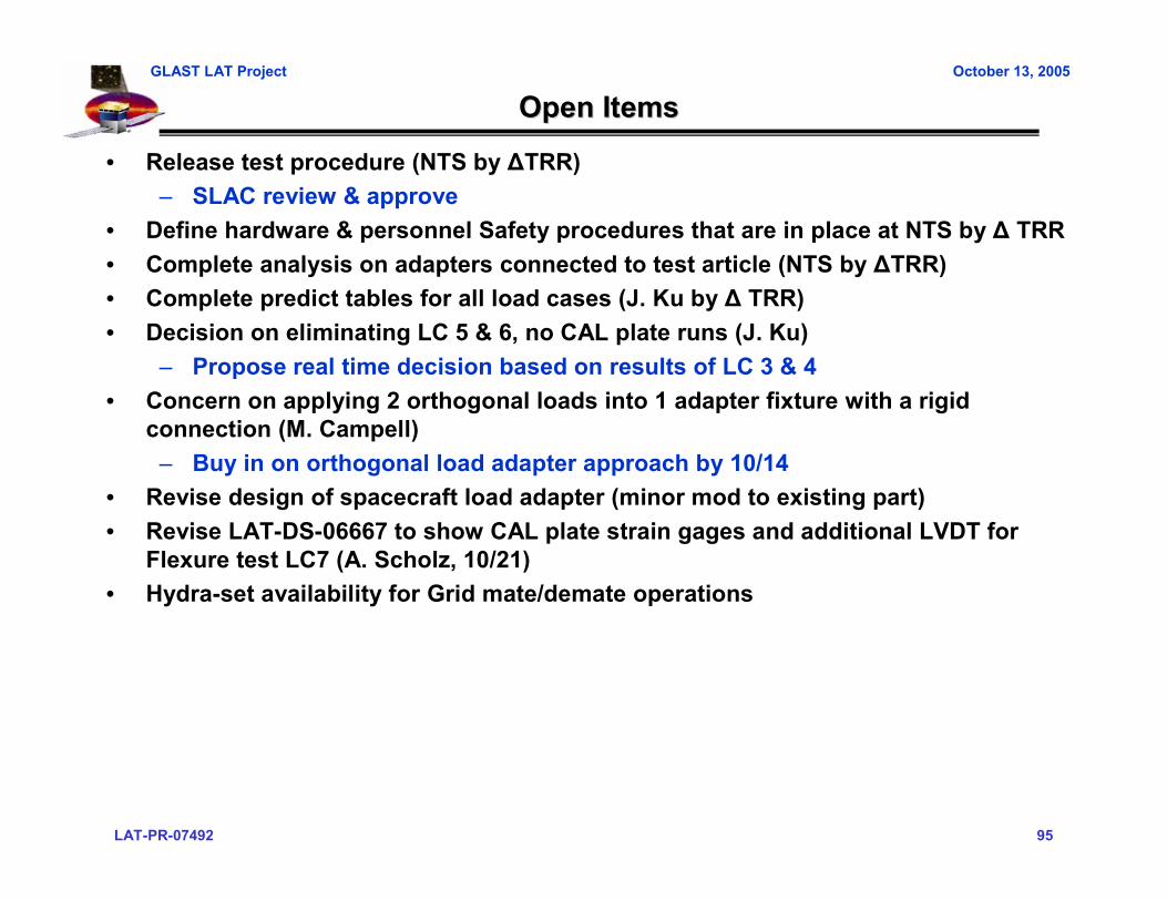
• Release test procedure (NTS by ∆TRR)– SLAC review & approve
• Define hardware & personnel Safety procedures that are in place at NTS by ∆ TRR• Complete analysis on adapters connected to test article (NTS by ∆TRR)• Complete predict tables for all load cases (J. Ku by ∆ TRR)• Decision on eliminating LC 5 & 6, no CAL plate runs (J. Ku)
– Propose real time decision based on results of LC 3 & 4• Concern on applying 2 orthogonal loads into 1 adapter fixture with a rigid
connection (M. Campell)– Buy in on orthogonal load adapter approach by 10/14
• Revise design of spacecraft load adapter (minor mod to existing part)• Revise LAT-DS-06667 to show CAL plate strain gages and additional LVDT for
Flexure test LC7 (A. Scholz, 10/21)• Hydra-set availability for Grid mate/demate operations
LAT-PR-07492 96
GLAST LAT Project October 13, 2005
ConclusionsConclusions
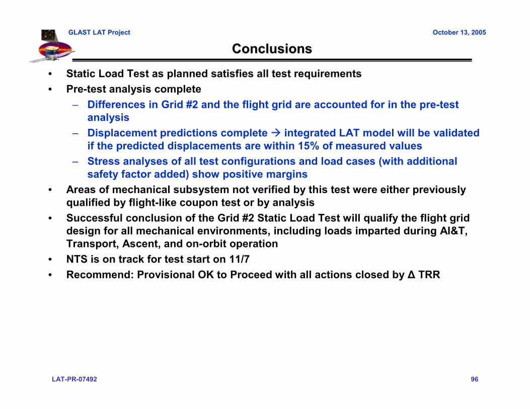
• Static Load Test as planned satisfies all test requirements• Pre-test analysis complete
– Differences in Grid #2 and the flight grid are accounted for in the pre-test analysis
– Displacement predictions complete integrated LAT model will be validated if the predicted displacements are within 15% of measured values
– Stress analyses of all test configurations and load cases (with additional safety factor added) show positive margins
• Areas of mechanical subsystem not verified by this test were either previously qualified by flight-like coupon test or by analysis
• Successful conclusion of the Grid #2 Static Load Test will qualify the flight grid design for all mechanical environments, including loads imparted during AI&T, Transport, Ascent, and on-orbit operation
• NTS is on track for test start on 11/7• Recommend: Provisional OK to Proceed with all actions closed by ∆ TRR
LAT-PR-07492 97
GLAST LAT Project October 13, 2005
Additional ActionAdditional Action Item ReviewItem Review
LAT-PR-07492 98
GLAST LAT Project October 13, 2005
Mechanical Systems
Grid #2 Static Load TestTest Readiness Review
Back –up material
Mechanical SystemsMechanical Systems
Grid #2 Static Load TestGrid #2 Static Load TestTest Readiness ReviewTest Readiness Review
Back Back ––up materialup material
LAT-PR-07492 99
GLAST LAT Project October 13, 2005
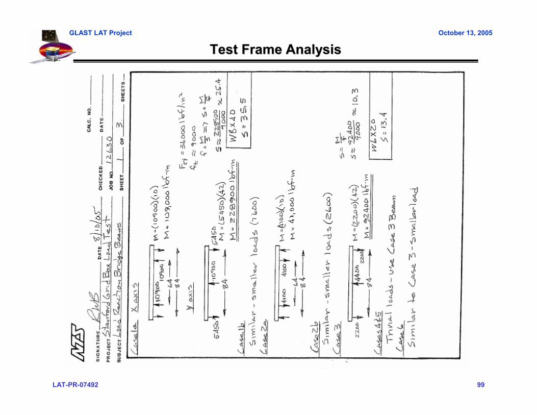
Test Frame AnalysisTest Frame Analysis

LAT-PR-07492 100
GLAST LAT Project October 13, 2005
Test Frame AnalysisTest Frame Analysis

LAT-PR-07492 101
GLAST LAT Project October 13, 2005
--106 Adapter Analysis106 Adapter Analysis