mechanical systems and signal processing · vibration control broadband frequency abstract the...
TRANSCRIPT
Mechanical Systems and Signal Processing 117 (2019) 609–633
Contents lists available at ScienceDirect
Mechanical Systems and Signal Processing
journal homepage: www.elsevier .com/locate /ymssp
Tailoring concurrent shear and translational vibration controlmechanisms in elastomeric metamaterials for cylindricalstructures
https://doi.org/10.1016/j.ymssp.2018.07.0490888-3270/� 2018 Elsevier Ltd. All rights reserved.
⇑ Corresponding author.E-mail address: [email protected] (R.L. Harne).
Sih-Ling Yeh, Ryan L. Harne ⇑Department of Mechanical and Aerospace Engineering, The Ohio State University, Columbus, OH 43210, USA
a r t i c l e i n f o
Article history:Received 10 May 2018Received in revised form 23 July 2018Accepted 26 July 2018
Keywords:MetamaterialsElastomersVibration controlBroadband frequency
a b s t r a c t
The implementation of engineered metamaterials in practical engineering structures forvibration control purposes is challenged by a lack of understanding on the specific interac-tion mechanisms present among finite-sized metamaterials and the greater host struc-tures. This research begins to address such knowledge gap by establishing an analyticalframework to study the dynamic response and coupling mechanisms between elastomericmetamaterial inclusions embedded within a cylindrical host structure, representative of avariety of engineering systems. The analysis is formulated based on energy methods, andapproximately solved by the Ritz method. Following experimental validation, the analysisis leveraged to reveal deep understanding on the precise mechanisms of coupling betweensuch elastomeric metamaterial inclusions and the host structure. Several non-intuitiveroles of parameter changes are conclusively revealed. For instance, while the decrease inopen angle ratio of the inclusion cross-section geometry and the increase in the centralcore radius both appear to increase the significance of the core mass, the analysis revealsthat the primary inclusion characteristic tuned by such parameter changes is the dynamicstiffness of the inclusions. Together, the dynamic mass and dynamic stiffness work toinduce two tuned-mass-damper-like behaviors that lead to broadband vibration attenua-tion capabilities. The results of this research encourage attention to the study of specificproblems whereby metamaterials directly interact with host structures to accuratelyunderstand the working mechanisms of vibration control for sake of optimal practicalimplementation.
� 2018 Elsevier Ltd. All rights reserved.
1. Introduction
A long-standing demand remains for exceptional vibration attenuation in many engineering applications. Lightweightmaterials that deliver high vibration attenuation capabilities extend the life of engineering systems and improve workingquality. With these aims in mind, previous researchers have investigated structural and material systems capable of atten-uating broadband vibration by using the concepts of tuned mass dampers, bandgap behavior, and constrained layereddampers.

610 S.-L. Yeh, R.L. Harne /Mechanical Systems and Signal Processing 117 (2019) 609–633
Tuned mass dampers (TMDs) are mass-spring-damper resonators capable of transferring the local vibration energy fromthe host structure to the mass-spring-damper. With this additional degree-of-freedom available, the vibration of the hoststructure may be suppressed by out-of-phase reaction force of the TMD with respect to the phase of the excitation force.Researchers have investigated tailoring this mechanism of vibration absorption via a variety of approaches. For example,Pai [1] proposed an elastic metamaterial with one-dimensional TMD subsystems to realize broadband vibration absorptionfor a one-dimensional host structure. The TMDs supply inertial forces that attenuate longitudinal wave propagation, includ-ing when the longitudinal wavelengths are much greater than the size of the periodic TMD subsystem, or unit cell. Similarly,Sun et al. [2] designed an elastic metamaterial beam with an array of TMD subsystems that exert shear forces and bendingmoments to absorb transverse wave propagation. Pai et al. [3] reported that using dual-mass TMD subsystems may enhancevibration absorption in two-dimensional structures while also broadening the range of frequencies of wave attenuation.Nonetheless, for each TMD the attenuation is only effective for a relatively narrow frequency range of resonance inherentto the TMDs or array of TMDs.
In a similar spirit to the resonant behavior of TMDs, bandgaps are a promising property of metamaterials for vibrationabsorption since waves are prohibited from propagating through the host structure at frequencies within the bandgap.The center frequency, bandwidth, and number of the bandgaps are related to the interrelationships among geometry, stiff-ness, and filling fraction of the metamaterials within the media. For example, Wang et al. [4] reported that the number ofbandgaps increases as the metamaterial is subjected to increasing compressive strain while the center frequency and band-width simultaneously reduce. With the aim to combine local resonance and bandgap behaviors, Matlack et al. [5] adoptedresonant elements embedded in a polycarbonate lattice to realize a broad Bragg bandgap. The bandgap breadth and centerfrequency were thus shown to be controlled by the local resonances. Indeed, the breadth of metamaterial concepts that exhi-bit bandgap behaviors are diverse and are inspiring for new approaches via their combination. For instance, Nouh et al. [6]presented a metamaterial plate composed of periodic cells with a small mass on a viscoelastic membrane, while Oh et al. [7]developed an elastic metamaterial insulator capable of creating a broad bandgap at low frequency by combined shear stiff-ening and rotation softening. Furthermore, for the chiral elastic metamaterial inclusions, Liu et al. [8] and Zhu et al. [9] inves-tigated chiral metamaterials with inclusions comprised of a core with coating layer. Also using a multi-material concept,Baravelli and Ruzzene [10] found that reduction of the filling fraction of the periodic elements caused the number of band-gaps to increase and the center frequency to decrease. Abdeljaber et al. [11] reported that the use of segmented, non-continuous, and non-periodic metamaterials may be advantageous for vibration and wave control in engineering structures.Although locally resonant bandgap mechanisms may provide useful means to suppress target bandwidths of elastic waves inhost structures, the bandwidth effected by such phenomena may be limited. Such limitation is inevitable when utilizing aparameter sensitive resonant behavior. Furthermore, designing these metamaterials to attenuate low frequency wavesrequires large size and often more material mass, which are undesirable aspects in practice.
Constrained layer damping (CLD) materials introduce an alternative strategy for vibration attenuation and typically usesmall added mass. The attenuation mechanism of CLD is attributed to the shear deformation in the thin and soft viscoelasticlayer between the host structure and the constraining layer. As a result, CLD provides vibration control most effectively atwavelengths on the order or shorter than the size of the applied CLD materials. This bounds the effective working range ofthe CLD to mid to high frequencies in practical applications. Using these principles, Aumjaud [12] developed a double shearlap-joint damper to yield high modal loss factor and amplitude reduction for a minimum of added mass. Additionally, pre-vious researchers discussed influences of the length, elastic modulus, thickness, structural damping, and interfacial dampingof the viscoelastic layer that is central to the CLD approach [13–20]. Douglas and Yang [21] concluded that the thin viscoelas-tic material provides broadband vibration attention by way of enhanced shear transfer to the viscoelastic layer, which agreeswith findings by Kerwin [22]. For thicker viscoelastic layers, the broadband attenuation of vibration is less apparent whereastransverse compressional damping phenomena may occur. Although conventional CLD may provide broadband attenuationat mid to high frequencies, the CLD must cover a large proportion of the host structure, which is challenging in practice andmay have side-effects, such as introducing a thermally insulating layer.
The survey above identifies promise and shortcomings for the variety of techniques for vibration attenuation: TMD, band-gap, and CLD. Recent work has sought to advance beyond these techniques by utilizing compression constraint on light-weight, elastomeric metamaterials. In this spirit, Bishop et al. [23] reported a lightweight hyperdamping metamaterialinclusion capable of attenuating more impact energy than the bulk material from which the metamaterial was derived.The concept was extended by Harne et al. [24] who utilized such inclusions to enhance noise control capabilities of poroe-lastic media. Yet, to date, the working mechanisms by which metamaterials enhancing vibration attenuation in host struc-tures has not been illuminated. Consequently, this research aims to build up an analytical framework to study thelightweight metamaterial inclusions, originally proposed in [23,24], as the inclusions interact with a host structure.
The metamaterial inclusions considered here are cylindrical so as to conform for a host structure that is a circular hollowtubular beam, a common component in automotive and aerospace structures as well as in mechanical equipment. The bot-tom left image of Fig. 1(a) illustrates the concept, where an elastomeric inclusion is embedded within a greater host structure(e.g. a long cylindrical tube). Several components to the cross-section may be identified using the general schematic at thetop of Fig. 1(a) shown by the four distinct layers. In Fig. 1(b), the annular metamaterial layer (labeled 2 in Fig. 1(a)) is the thinouter-most component of the metamaterial that is between the host structure (labeled 1) and the porous metamaterial layer(labeled 3). The core bulk metamaterial layer (labeled 4) at the center of the metamaterial is a mass. All together, the radiallyarrayed beams are analogous to a soft elastic layer.
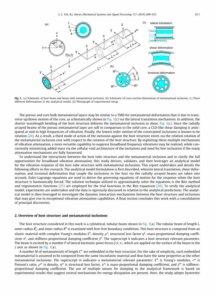
Fig. 1. (a) Schematic of host beam and beam with metamaterial inclusion. (b) Schematic of cross-section dimensions of metamaterial inclusion. (c) Threedifferent deformations in the analytical model. (d) Photograph of experimental setup.
S.-L. Yeh, R.L. Harne /Mechanical Systems and Signal Processing 117 (2019) 609–633 611
The porous and core bulk metamaterial layers may be similar to a TMD for metamaterial deformation that is due to trans-verse up/down motion of the core, as schematically shown in Fig. 1(c) via the lateral translation mechanism. In addition, theshorter wavelength bending of the host structure deforms the metamaterial inclusion in shear, Fig. 1(c). Since the radiallyarrayed beams of the porous metamaterial layer are soft in comparison to the solid core, a CLD-like shear damping is antic-ipated at mid to high frequencies of vibration. Finally, the lowest order motion of the constrained inclusions is known to berotation [24]. As a result, a third mode of action of the inclusion against the host structure exists via the relation rotation ofthe metamaterial inclusion core with respect to the rotation of the host structure. By exploiting these multiple mechanismsof vibration attenuation, a more versatile capability to suppress broadband frequency vibrations may be realized, while con-currently minimizing added mass via the cellular void architecture of the inclusions and need for few inclusions if the manyattenuation mechanisms are fully harnessed.
To understand the interactions between the host tube structure and the metamaterial inclusion and to clarify the fullopportunities for broadband vibration attenuation, this study devises, validates, and then leverages an analytical modelfor the vibration response of the host tube structure with metamaterial inclusions. This report undertakes and details thefollowing efforts in this research. The analytical model formulation is first described, wherein lateral translation, shear defor-mation, and torsional deformation that couple the inclusions to the host via the radially arrayed beams are taken intoaccount. Euler-Lagrange equations are used to derive the governing equations of motion for the response when the hoststructure is harmonically forced. The solution technique utilized to approximately solve the equations is the Ritz methodand trigonometric functions [25] are employed for the trial functions in the Ritz expansion [26]. To verify the analyticalmodel, experiments are undertaken and the data is rigorously discussed in relation to the analytical predictions. The analyt-ical model is then leveraged to investigate the dynamic interaction mechanisms between the host structure and inclusionsthat may give rise to exceptional vibration attenuation capabilities. A final section concludes this work with a consolidationof principal discoveries.
2. Overview of host structure and metamaterial inclusions
The host structure considered in this work is a cylindrical, tubular beam shown in Fig. 1(a). The tubular beam of length L,
outer radius Rho , and inner radius Rh is examined with free-free boundary conditions. This host structure is composed from an
elastic material with complex Young’s modulus Eh, density qh, structural loss factor gh, mass-proportional damping coeffi-cient ah, and stiffness-proportional damping coefficient bh. The superscript h indicates a host structure relevant parameter.The beam is excited by a number P of lateral harmonic point forces f x; tð Þ, which are applied on the surface of the beam in thez axis as shown in Fig. 1(a).
A numberM of metamaterials of length Lm are embedded in the host structure. For the sake of simplicity, each embeddedmetamaterial is assumed to be composed from the same viscoelastic material and thus have the same properties as the othermetamaterial inclusions. The superscript m indicates a metamaterial relevant parameter: Em is Young’s modulus, mm isPoisson’s ratio, qm is density, gm is structural loss factor, am is mass-proportional damping coefficient, and bm is stiffness-proportional damping coefficient. The use of multiple means for damping in the analytical framework is based onexperimental results that suggest several mechanisms for energy dissipation are present. Here, the study adopts hysteretic
612 S.-L. Yeh, R.L. Harne /Mechanical Systems and Signal Processing 117 (2019) 609–633
damping and Rayleigh damping. The damping coefficients are identified empirically, which is the commonly adopted tech-nique [27,28].
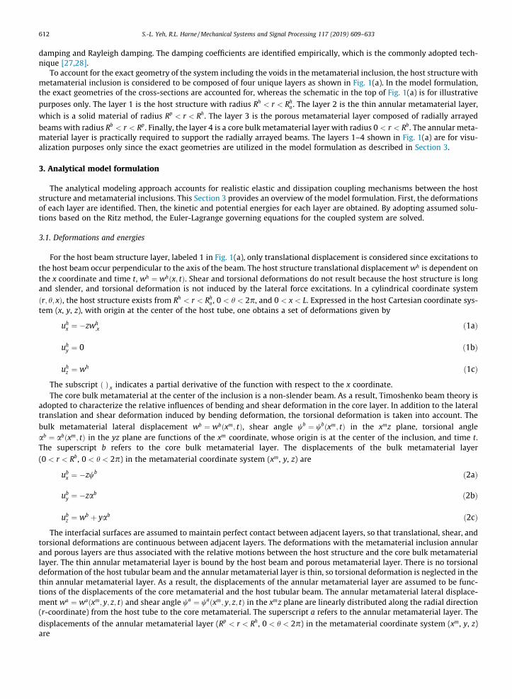
To account for the exact geometry of the system including the voids in the metamaterial inclusion, the host structure withmetamaterial inclusion is considered to be composed of four unique layers as shown in Fig. 1(a). In the model formulation,the exact geometries of the cross-sections are accounted for, whereas the schematic in the top of Fig. 1(a) is for illustrative
purposes only. The layer 1 is the host structure with radius Rh < r < Rho . The layer 2 is the thin annular metamaterial layer,
which is a solid material of radius Rp < r < Rh. The layer 3 is the porous metamaterial layer composed of radially arrayed
beams with radius Rb < r < Rp. Finally, the layer 4 is a core bulk metamaterial layer with radius 0 < r < Rb. The annular meta-material layer is practically required to support the radially arrayed beams. The layers 1–4 shown in Fig. 1(a) are for visu-alization purposes only since the exact geometries are utilized in the model formulation as described in Section 3.
3. Analytical model formulation
The analytical modeling approach accounts for realistic elastic and dissipation coupling mechanisms between the hoststructure and metamaterial inclusions. This Section 3 provides an overview of the model formulation. First, the deformationsof each layer are identified. Then, the kinetic and potential energies for each layer are obtained. By adopting assumed solu-tions based on the Ritz method, the Euler-Lagrange governing equations for the coupled system are solved.
3.1. Deformations and energies
For the host beam structure layer, labeled 1 in Fig. 1(a), only translational displacement is considered since excitations tothe host beam occur perpendicular to the axis of the beam. The host structure translational displacement wh is dependent onthe x coordinate and time t, wh ¼ wh x; tð Þ. Shear and torsional deformations do not result because the host structure is longand slender, and torsional deformation is not induced by the lateral force excitations. In a cylindrical coordinate system
r; h; xð Þ, the host structure exists from Rh < r < Rho , 0 < h < 2p, and 0 < x < L. Expressed in the host Cartesian coordinate sys-
tem (x, y, z), with origin at the center of the host tube, one obtains a set of deformations given by
uhx ¼ �zwh
;x ð1aÞ
uhy ¼ 0 ð1bÞ
uhz ¼ wh ð1cÞ
The subscript ð Þ;x indicates a partial derivative of the function with respect to the x coordinate.The core bulk metamaterial at the center of the inclusion is a non-slender beam. As a result, Timoshenko beam theory is
adopted to characterize the relative influences of bending and shear deformation in the core layer. In addition to the lateraltranslation and shear deformation induced by bending deformation, the torsional deformation is taken into account. Thebulk metamaterial lateral displacement wb ¼ wb xm; tð Þ, shear angle wb ¼ wb xm; tð Þ in the xmz plane, torsional angleab ¼ ab xm; tð Þ in the yz plane are functions of the xm coordinate, whose origin is at the center of the inclusion, and time t.The superscript b refers to the core bulk metamaterial layer. The displacements of the bulk metamaterial layer
(0 < r < Rb, 0 < h < 2p) in the metamaterial coordinate system (xm, y, z) are
ubx ¼ �zwb ð2aÞ
uby ¼ �zab ð2bÞ
ubz ¼ wb þ yab ð2cÞ
The interfacial surfaces are assumed to maintain perfect contact between adjacent layers, so that translational, shear, andtorsional deformations are continuous between adjacent layers. The deformations with the metamaterial inclusion annularand porous layers are thus associated with the relative motions between the host structure and the core bulk metamateriallayer. The thin annular metamaterial layer is bound by the host beam and porous metamaterial layer. There is no torsionaldeformation of the host tubular beam and the annular metamaterial layer is thin, so torsional deformation is neglected in thethin annular metamaterial layer. As a result, the displacements of the annular metamaterial layer are assumed to be func-tions of the displacements of the core metamaterial and the host tubular beam. The annular metamaterial lateral displace-ment wa ¼ wa xm; y; z; tð Þ and shear angle wa ¼ wa xm; y; z; tð Þ in the xmz plane are linearly distributed along the radial direction(r-coordinate) from the host tube to the core metamaterial. The superscript a refers to the annular metamaterial layer. The
displacements of the annular metamaterial layer (Rp < r < Rh, 0 < h < 2p) in the metamaterial coordinate system (xm, y, z)are
S.-L. Yeh, R.L. Harne /Mechanical Systems and Signal Processing 117 (2019) 609–633 613
uax ¼ �zwa ð3aÞ
uay ¼ 0 ð3bÞ
uaz ¼ wa ð3cÞ
where wa ¼ r�Rb
Rh�Rbwh þ Rh�r
Rh�Rbwb and wa ¼ r�Rb
Rh�Rbwh
;x þ Rh�rRh�Rb
wb.
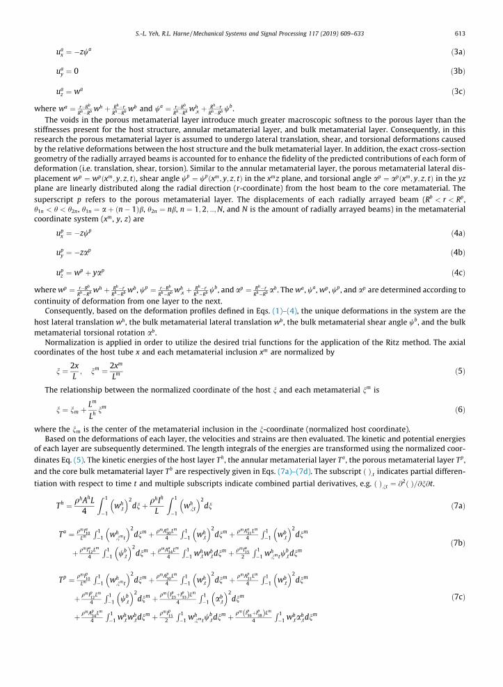
The voids in the porous metamaterial layer introduce much greater macroscopic softness to the porous layer than thestiffnesses present for the host structure, annular metamaterial layer, and bulk metamaterial layer. Consequently, in thisresearch the porous metamaterial layer is assumed to undergo lateral translation, shear, and torsional deformations causedby the relative deformations between the host structure and the bulk metamaterial layer. In addition, the exact cross-sectiongeometry of the radially arrayed beams is accounted for to enhance the fidelity of the predicted contributions of each form ofdeformation (i.e. translation, shear, torsion). Similar to the annular metamaterial layer, the porous metamaterial lateral dis-placement wp ¼ wp xm; y; z; tð Þ, shear angle wp ¼ wp xm; y; z; tð Þ in the xmz plane, and torsional angle ap ¼ ap xm; y; z; tð Þ in the yzplane are linearly distributed along the radial direction (r-coordinate) from the host beam to the core metamaterial. The
superscript p refers to the porous metamaterial layer. The displacements of each radially arrayed beam (Rb < r < Rp,h1n < h < h2n, h1n ¼ aþ n� 1ð Þb, h2n ¼ nb, n ¼ 1;2; ::;N, and N is the amount of radially arrayed beams) in the metamaterialcoordinate system (xm, y, z) are
upx ¼ �zwp ð4aÞ
upy ¼ �zap ð4bÞ
upz ¼ wp þ yap ð4cÞ
wherewp ¼ r�Rb
Rh�Rbwh þ Rh�r
Rh�Rbwb, wp ¼ r�Rb
Rh�Rbwh
;x þ Rh�rRh�Rb
wb, and ap ¼ Rh�rRh�Rb
ab. Thewa, wa,wp, wp, and ap are determined according to
continuity of deformation from one layer to the next.Consequently, based on the deformation profiles defined in Eqs. (1)–(4), the unique deformations in the system are the
host lateral translation wh, the bulk metamaterial lateral translation wb, the bulk metamaterial shear angle wb, and the bulkmetamaterial torsional rotation ab.
Normalization is applied in order to utilize the desired trial functions for the application of the Ritz method. The axialcoordinates of the host tube x and each metamaterial inclusion xm are normalized by
n ¼ 2xL; nm ¼ 2xm
Lmð5Þ
The relationship between the normalized coordinate of the host n and each metamaterial nm is
n ¼ nm þ Lm
Lhnm ð6Þ
where the nm is the center of the metamaterial inclusion in the n-coordinate (normalized host coordinate).Based on the deformations of each layer, the velocities and strains are then evaluated. The kinetic and potential energies
of each layer are subsequently determined. The length integrals of the energies are transformed using the normalized coor-
dinates Eq. (5). The kinetic energies of the host layer Th, the annular metamaterial layer Ta, the porous metamaterial layer Tp,
and the core bulk metamaterial layer Tb are respectively given in Eqs. (7a)–(7d). The subscript ð Þ;t indicates partial differen-tiation with respect to time t and multiple subscripts indicate combined partial derivatives, e.g. ð Þ;nt ¼ @2ð Þ=@n@t.
Th ¼ qhAhL4
Z 1
�1wh
;t
� �2dnþ qhIh
L
Z 1
�1wh
;nt
� �2dn ð7aÞ
Ta ¼ qmIa10Lm
R 1�1 wh
;nmt
� �2dnm þ qmAa
30Lm
4
R 1�1 wh
;t
� �2dnm þ qmAa
31Lm
4
R 1�1 wb
;t
� �2dnm
þ qmIa12Lm
4
R 1�1 wb
;t
� �2dnm þ qmAa
34Lm
4
R 1�1 w
h;tw
b;tdn
m þ qmIa152
R 1�1 w
h;nmtw
b;tdn
mð7bÞ
Tp ¼ qmIp10Lm
R 1�1 wh
;nmt
� �2dnm þ qmAp
30Lm
4
R 1�1 wh
;t
� �2dnm þ qmAp
31Lm
4
R 1�1 wb
;t
� �2dnm
þ qmIp12Lm
4
R 1�1 wb
;t
� �2dnm þ qm Ip23þIp33ð ÞLm
4
R 1�1 ab
;t
� �2dnm
þ qmAp34Lm
4
R 1�1 w
h;tw
b;tdn
m þ qmIp15
2
R 1�1 w
h;nmtw
b;tdn
m þ qm Ip36þIp38ð ÞLm4
R 1�1 w
b;tab
;tdnm
ð7cÞ

614 S.-L. Yeh, R.L. Harne /Mechanical Systems and Signal Processing 117 (2019) 609–633
Tb ¼ qmAb31L
m
4
Z 1
�1wb
;t
� �2dnm þ qmIb12L
m
4
Z 1
�1wb
;t
� �2dnm þ
qm Ib23 þ Ib33� �
Lm
4
Z 1
�1ab;t
� �2dnm ð7dÞ
The expressions for the undefined coefficients of each layer in Eq. (7) are given in Appendix A. The potential energies of
the host layer Uh, the annular metamaterial layer Ua, the porous metamaterial layer Up, and the core bulk metamaterial layer
Ub are respectively presented in Eqs. (8a)–(8d).
Uh ¼ 4E�hIh
L3
Z 1
�1wh
;nn
� �2dn ð8aÞ
Ua ¼ 4E�mIa10Lmð Þ3
Z 1
�1wh
;nmnm
� �2dnm þ G
�mka Aa
50 þ Aa60
� �Lm
Z 1
�1wh
;nm
� �2dnm
þE�mIa30 þ G
�mkaJa40
� �Lm
4
Z 1
�1wh� �2
dnm
þG�mkaAa
51
Lm
Z 1
�1wb
;nm
� �2dnm þ
E�mIa31 þ G
�mkaJa41
� �Lm
4
Z 1
�1wb� �2
dnm
þ E�mIa12Lm
Z 1
�1wb
;nm
� �2dnm þ G
�mka Aa
52 þ Aa62
� �Lm
4
Z 1
�1wb� �2
dnm
�G�mkaAa
54
Lm
Z 1
�1wh
;nmwb;nmdn
m �E�mIa34 þ G
�mkaJa44
� �Lm
4
Z 1
�1whwbdnm
þ2E�mIa15Lmð Þ2
Z 1
�1wh
;nmnmwb;nmdn
m � G�mka Aa
55 þ Aa65
� �2
Z 1
�1wh
;nmwbdnm þ G
�mkaAa
57
2
Z 1
�1wb
;nmwbdnm
ð8bÞ
Up¼4E�mIp10Lmð Þ3
Z 1
�1wh
;nmnm
� �2dnmþG
�mkp Ap
50þAp60
� �Lm
Z 1
�1wh
;nm
� �2dnm
þE�mIp30þG
�mkpJp40
� �Lm
4
Z 1
�1wh� �2
dnm
þG�mkpAp
51
Lm
Z 1
�1wb
;nm
� �2dnmþ
E�mIp31þG
�mkpJp41
� �Lm
4
Z 1
�1wb� �2
dnm
þE�mIp12Lm
Z 1
�1wb
;nm
� �2dnmþG
�mkp Ap
52þAp62
� �Lm
4
Z 1
�1wb� �2
dnm
þG�mkp Jp53þJp63� �Lm
Z 1
�1ab;nm
� �2dnmþ
E�mAp
23þE�mAp
33þG�mkpAp
43
� �Lm
4
Z 1
�1ab� �2
dnm
�G�mkpAp
54
Lm
Z 1
�1wh
;nmwb;nmdn
m�E�mJp34þG
�mkpJp44
� �Lm
4
Z 1
�1whwbdnm
þ2E�mIp15Lmð Þ2
Z 1
�1wh
;nmnmwb;nmdn
m�G�mkp Ap
55þAp65
� �2
Z 1
�1wh
;nmwbdnm
�G�mkp Jp56�Jp66� �Lm
Z 1
�1wh
;nmab;nmdn
m�E�mJp36�G
�mkpJp46
� �Lm
4
Z 1
�1whabdnm
þG�mkpAp
57
2
Z 1
�1wb
;nmwbdnmþG
�mkpJp58Lm
Z 1
�1wb
;nmab;nmdn
m
þE�mJp38�G
�mkpJp48
� �Lm
4
Z 1
�1whabdnm�G
�mkp Jp69�Jp59� �2
Z 1
�1wbab
;nmdnm
ð8cÞ

Table 1Coeffici
k
1234>4
S.-L. Yeh, R.L. Harne /Mechanical Systems and Signal Processing 117 (2019) 609–633 615
Ub ¼ G�mkbAb
51
Lm
Z 1
�1wb
;nm
� �2dnm þ E
�mIb12Lm
Z 1
�1wb
;nm
� �2dnm þ G
�mkbAb
52Lm
4
Z 1
�1wb� �2
dnm
þG�mkb Jb53 þ Jb63� �Lm
Z 1
�1ab;nm
� �2dnm � G
�mkbAb
57
2
Z 1
�1wbwb
;nmdnm
ð8dÞ
Here, E�h
¼ Eh 1þ jgh� �
and E�m
¼ Em 1þ jgmð Þ are the complex Young’s modulus of the host beam and the metamaterial,
respectively. The G�m
¼ E�m
= 2 1þ mmð Þ½ � is the complex shear modulus of the metamaterial. The ka ¼ 2 1þ mmð Þ= 4þ 3mmð Þ,kp ¼ 10 1þ mmð Þ= 12þ 11mmð Þ, and kb ¼ 6 1þ mmð Þ= 7þ 6mmð Þ are the shear coefficients in Timoshenko’s beam theory for theannular metamaterial layer, porous metamaterial layer, and the bulk metamaterial layer, respectively. The formulas ofthe shear coefficients are derived by Cowper [29] in accordance with the unique cross-section geometries of each layer.
The expressions for the coefficients in Eq. (8) are provided in Appendix A. The work Wb of the applied lateral force per unitlength in the n-coordinate, f n; tð Þ, is given by
Wb ¼ L2
Z 1
�1whf n; tð Þdn ð9Þ
3.2. Euler-Lagrange governing equations and Ritz method solution approach
The Ritz method is employed to approximately solve the Euler-Lagrange governing equations for the system. A set oftrigonometric functions /k gð Þ created by Beslin and Nicolas [25] is employed as the trial functions in the Ritz method expan-sion. The utility and computational efficiency of the trigonometric functions have been extensively assessed by Dozio [26].The trigonometric functions /k gð Þ used as the trial functions in this work are
/k gð Þ ¼ sin akgþ bkð Þsin ckgþ dkð Þ ð10Þ
The coefficients ak, bk, ck, and dk are listed in Table 1. The selection of trial functions among the full trigonometric functionset are determined by the boundary conditions. The analysis of the free-free host beam lateral displacement wh and of thefree-free core bulk metamaterial inclusion lateral displacement wb retain all of the trigonometric functions of the set. Thefunctions /2 gð Þ and /4 gð Þ are removed from the sequences utilized to account for the shear angle wb and torsional angleab of the core bulk metamaterial layer based on the boundary conditions. The host lateral displacement wh, core bulk meta-material lateral displacement wb, shear angle wb, and torsional angle ab are
wh n; tð Þ ¼ ahbf tð Þ/hbf nð Þ
wb nm; tð Þ ¼ bmbg tð Þ/mb
g nmð Þwb nm; tð Þ ¼ cms
h tð Þ/msh nmð Þ
ab nm; tð Þ ¼ dmti tð Þ/mt
i nmð Þ
ð11a-dÞ
where ahbf , bmb
g , cmsh , and dmt
i are unknown generalized coordinates [30] to be determined, and /hbf , /mb
g , /msh , and /mt
i are trial
functions defined according to Eq. (10), where g is replaced by n or nm, and k is replaced by f , g, h, or i. The superscripts hb,mb, ms, and mt refer to the following. The hb refers to host lateral displacement induced by bending, mb refers to metama-terial lateral displacement induced by bending, ms refers to metamaterial shear displacement induced by bending, and mtrefers to metamaterial torsional displacement.
The Lagrangian functional of the coupled system is
L ¼ Th þ Ta þ Tp þ Tb � Uh þ Ua þ Up þ Ub� �
þWb ð12Þ
The Euler-Lagrange governing equations for the system are
ents of trigonometric functions set.
ak bk ck dk
p=4 3p=4 p=4 3p=4p=4 3p=4 �p=2 �3p=2p=4 �3p=4 p=4 �3p=4p=4 �3p=4 p=2 �3p=2p k� 4ð Þ=2 p k� 4ð Þ=2 p=2 p=2

616 S.-L. Yeh, R.L. Harne /Mechanical Systems and Signal Processing 117 (2019) 609–633
ddt
@L
@ _ahbf
!� @L@ahbf
¼ 0 ð13aÞ
ddt
@L
@ _bmb
g
0@
1A� @L
@bmbg
¼ 0 ð13bÞ
ddt
@L
@c_msh
0@
1A� @L
@cmsh
¼ 0 ð13cÞ
ddt
@L
@ _dmt
i
!� @L
@dmti
¼ 0 ð13dÞ
The time-dependent governing equations assume steady-state time-harmonic responses. As a result, the unknown gen-eralized coordinates and the lateral force applied on the host structure exhibit time dependence of the form
ahbf ¼ Ahbf ejxt; bmb
g ¼ Bmbg ejxt ; cms
h ¼ Cmsh ejxt; dmt
i ¼ Dmti ejxt ; f ¼ Fhb
f ejxt ð14a-eÞ
Substituting Eq. (14) into Eq. (13), the governing equations in the matrix form is�x2 M½ � þ jx C½ � þ K½ �� �qf g ¼ Ff g ð15Þ
where the mass matrix M½ �, stiffness matrix K½ �, unknown constants qf g, and forcing vector Ff g are Eq. (16)–(19),respectively.
M½ � ¼
Mhbhbfp Mhb1b
fq Mhb1sfr Mhb1t
fs � � � Mhbmbfq Mhbms
fr Mhbmtfs
M1b1bgq M1b1s
gr M1b1tgs 0 0 0 0
M1s1shr M1s1t
hs... ..
. ... ..
.
M1t1tis 0 ..
. ... ..
.
. ..
0 0 0Mmbmb
gq Mmbmsgr Mmbmt
gs
sym Mmsmshr Mmsmt
hs
Mmtmtis
26666666666666666664
37777777777777777775
ð16Þ
K½ � ¼
Khbhbfp Khb1b
fq Khb1sfr Khb1t
fs � � � Khbmbfq Khbms
fr Khbmtfs
K1b1bgq K1b1s
gr K1b1tgs 0 0 0 0
K1s1shr K1s1t
hs... ..
. ... ..
.
K1t1tis 0 ..
. ... ..
.
. ..
0 0 0Kmbmb
gq Kmbmsgr Kmbmt
gs
sym Kmsmshr Kmsmt
hs
Kmtmtis
26666666666666666664
37777777777777777775
ð17Þ
qf g ¼ Ahbf B1b
g C1sh D1t
i � � � Bmbg Cms
h Dmti
n oT ð18Þ
Ff g ¼ Fhbf 0 0 0 � � � 0 0 0
n oT ð19Þ
The components of the damping matrix are C½ � ¼ amRe M½ � þ bmRe K½ �, whereas the damping of the host tubular beam is
Chbhbfp ¼ ahMhbhb
fp þ bhKhbhbfp . Thus, for the inclusions both viscous and structural damping mechanisms are accounted for
[31]. The detailed components of the mass matrix M½ �, stiffness matrix K½ �, and force vector Ff g are listed in Appendix A. Solu-
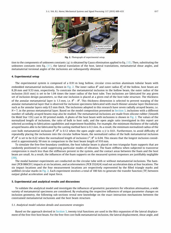
Fig. 2. Photograph of experimental setup.
S.-L. Yeh, R.L. Harne /Mechanical Systems and Signal Processing 117 (2019) 609–633 617
tion to the components of unknown constants qf g is obtained by Gauss elimination applied to Eq. (15). Then, substituting theunknown constants into Eq. (11), the lateral translation of the host, lateral translations, metamaterial shear angles, andmetamaterial torsional angles of the inclusions are subsequently obtained.
4. Experimental setup
The experimental system is composed of a 0.91 m long hollow, circular cross-section aluminum tubular beam with
embedded metamaterial inclusions, shown in Fig. 2. The inner radius Rh and outer radius Rho of the hollow, host beam are
8.28 mm and 9.53 mm, respectively. To constrain the metamaterial inclusion in the hollow beam, the outer radius of theinclusion (8.61 mm) is set to be 1.04 times the inner radius of the host tube. Two inclusions are fabricated for any givenset of inclusion design parameters, so that one inclusion is placed at a given end of the host tube structure. The thickness
of the annular metamaterial layer is 1.5 mm, i.e. Rh � Rp. This thickness dimension is selected to prevent warping of theannular metamaterial layer that is observed for inclusion specimens fabricated with much thinner annular layer thicknessessuch as for annular layers only 0.5 mm thick. The inclusions adopted in this research have seven radially arrayed beams, i.e.N = 7, in the porous metamaterial layer. Based on the model composition presented in Section 3, inclusions with a differentnumber of radially arrayed beams may also be studied. The metamaterial inclusions are made from silicone rubber (SmoothOn Mold Star 15S) cast in 3D printed molds. A photo of the host beam with inclusions is shown in Fig. 2. The values of thenormalized length of inclusions, the ratio of bulk to host radii, and the open angle ratio investigated in this report areselected according to fabrication capabilities and experiment feasibility. For example, the minimum thickness of the radiallyarrayed beams able to be fabricated by the casting method here is 0.3 mm. As a result, the minimum normalized radius of the
core bulk metamaterial inclusion Rb=Rh is 0.12 when the open angle ratio a=b is 0.61. Furthermore, to avoid difficulty ofrepeatedly placing the inclusions into the circular hollow beam, the normalized radius of the bulk metamaterial inclusion
Rb=Rh is set to be 0.22 when the normalized length of inclusion Lm=Rh is 6.04. This means that the longest inclusion consid-ered is approximately 50 mm in comparison to the host beam length of 910 mm.
To simulate the free-free boundary condition, the host tubular beam is placed on two triangular foam supports that arerandomly positioned to avoid suppressing particular modes of vibration. The foam stiffness when subjected to transversecompression is much less than the stiffnesses present in the system, and the contact areas between the foam and the hostbeam are small. As a result, the influences of the foam supports on the measured system responses are justifiably negligible[30].
The modal hammer experiments are conducted on the circular tube with or without metamaterial inclusions. The ham-mer (PCB 086C01) impacts at six locations, and accelerometers (PCB 352A24) read out acceleration data at four locations. Thesix impact locations and the four measurement locations are respectively represented by the filled triangle marks andunfilled circular marks in Fig. 2. Each experiment involves a total of 180 hits to generate the transfer function (TF) betweenoutput global acceleration and input force.
5. Experimental and analytical results and discussions
To validate the analytical model and investigate the influences of geometric parameters for vibration attenuation, a widevariety of metamaterial specimens are considered. By evaluating the respective influences of unique parameter changes oninclusion geometry, the following sub-sections reveal new knowledge on the exact interaction mechanisms between theconstrained metamaterial inclusions and the host beam structure.
5.1. Analytical model solution details and assessment strategies
Based on the approach devised in Section 3, twenty trial functions are used in the Ritz expansion of the lateral displace-ment of the free-free host beam. For the free-free core bulk metamaterial inclusion, the lateral displacement, shear angle, and

618 S.-L. Yeh, R.L. Harne /Mechanical Systems and Signal Processing 117 (2019) 609–633
torsional angle are expanded in the Ritz method assumed solutions using ten, eight, and eight trial functions, respectively.These numbers of trial functions are selected based on a convergence study that identified no significant change in analyticalmodel predictions for greater number of trial functions in the frequency range of interest: 100–10,000 Hz. In the analyticalmodel, to characterize the global vibration response of the host structure and inclusions the applied, lateral point forces tothe beam are given at 201 randomly selected positions. The final force vector is the sum of all force vectors of the 201 ran-dom positions. This approach is found, through model studies, to yield a global vibration response of the system. Althoughthe experiment is unable to yield as ideal global vibration response, the comparisons between analysis and experiment thatfollow in subsequent sub-sections suggests that the experiment mostly approaches the trends of a global response.
In this study, the validations are taken by comparison of the TF reduction and frequency reduction between experimentand analysis. The analytical TF between acceleration at the beam locations and the impact forces is obtained. The global TFspresented in narrowband studies are determined by the square root of the sum of squares of the TFs computed for each com-bination of acceleration evaluation and impact force location. The TF reductions are determined from the narrowband TFs indecibels of the host beam without inclusions subtracted from the TFs in decibels evaluated when the host beam has inclu-sions. To investigate the TF reductions for each mode, the frequency ranges for the six lowest order modes, over which thecumulative TF reductions are computed, are 85–180 Hz, 250–500 Hz, 500–890 Hz, 890–1450 Hz, 1450–2100 Hz, and 2100–2850 Hz. These ranges sufficiently encompass the six lowest order modes. Similarly, the resonant frequency reductions arefound by tracking the peak amplitude of the narrowband TF in these frequency ranges as it shifts for the case of the hostbeam with inclusions compared to the case of the host beam without inclusions. Table 2 provides all of the relevant material
Table 2Material properties of host structure and metamaterial inclusions.
Young’s modulus[Pa]
Poisson’sratio
density [kg/m3]
structural lossfactor
mass-proportional dampingcoefficient
stiffness-proportional dampingcoefficient
Beam 68.9 � 109 0.33 2700 0.0015 1 � 10�9 1 � 10�9
Inclusions 752 � 103 0.49 1145 0.02 5 � 10�5 9 � 10�5
Fig. 3. (a) Experimental TF frequency responses, (b) analytical TF frequency responses, (c) experimental TF reductions, (d) analytical TF reductions, (e)experimental frequency reductions, and (f) analytical frequency reductions for four lengths of inclusions, Lm=Rh = 0.78, 1.54, 4.22, and 6.04. The radius ratioRb=Rh is 0.22 while the open angle ratio a=b is 0.61.

Fig. 4. (a) Experimental TF frequency responses, (b) analytical TF frequency responses, (c) experimental TF reduction, (d) analytical TF reduction, (e)experimental frequency reduction, and (f) analytical frequency reduction for four radii of core bulk metamaterial inclusions, Rb=Rh = 0.12, 0.22, 0.45, and0.73, and for the solid inclusions. For the metamaterial inclusions, the length ratio Lm=Rh is 4.22 while the open angle ratio a=b is 0.61.
S.-L. Yeh, R.L. Harne /Mechanical Systems and Signal Processing 117 (2019) 609–633 619
properties used in all analytical computations. The parameters are identified empirically from the experimental system. Theremaining parameters used in the model to characterize unique inclusion designs are described in the respective sub-sections that follow.
5.2. Influences on length of metamaterial
The experimental and analytical frequency responses of the TFs are shown in Fig. 3 for four values of normalized lengths
of inclusions, Lm=Rh = 0.77, 1.54, 4.22, and 6.04. For the metamaterials considered in Fig. 3, the ratio of bulk to host radii Rb=Rh
is 0.22 while the open angle ratio a=b is 0.61.In the results of Fig. 3 as well as for Figs. 4 and 5, there are a few minor discrepancies between the experiments and ana-
lytical predictions worth noting. For the six lowest order modes, the deviations between the experimental and analytical res-onant frequencies of the bare beam are less than 5%. These discrepancies may be due to small imperfection in the knowledgeof the host beammaterial properties. Also, the experimental TF of the bare beam does not reveal as great of amplitude at lowand high frequencies as that in the model. This is caused by the modal impact hammer experimental technique that is chal-lenged to induce wide-band frequency energy, which is due to the selection of an impact hammer tip that is necessarily bestsuited to inject energy within a finite range of frequencies. Despite these discrepancies, the observed influences in analysisand experiments of inserting the inclusions are found through Figs. 3–5 to be in relatively good agreement as discussed inthis and the following sub-sections of Section 5. As such, the minor discrepancies between experiment and analysisdescribed in this paragraph are concluded to be of negligible significance towards formulating conclusions regarding theinteraction mechanisms observed between the inclusions and host.
While the narrowband experimental data, Fig. 3(a), and analytical predictions, Fig. 3(b), are in good overall agreement, themore synthesized results of Fig. 3(c)–(f) are of primary interest towards understanding the influences of change in the inclu-sion length. Specifically, Fig. 3(c) and (d) respectively present the experimental and analytical TF reductions of the lowest sixmodes for different length of inclusions. In general, the TF reduction increases for increase in the length of the inclusions.This result is intuitive on the basis of added mass increase with increase in inclusion length, so that the added mass or ballasthelps to suppress the host beam vibration.

Fig. 5. (a) Experimental TF frequency responses, (b) analytical TF frequency responses, (c) experimental TF reduction, (d) analytical TF reduction, (e)experimental frequency reduction, and (f) analytical frequency reduction of the host beam with inclusions with four different open angle ratios of theradially arrayed beams, a=b = 0.25, 0.41, 0.61, and 0.80, and for the solid inclusions. The length ratio Lm=Rh is 4.22 while the radius ratio Rb=Rh is 0.45.
620 S.-L. Yeh, R.L. Harne /Mechanical Systems and Signal Processing 117 (2019) 609–633
Fig. 3(e) and (f) present the experimental and analytical frequency reductions of the lowest six modes for different lengthof inclusions, respectively. The frequency shift for each mode increases for increase in the length of the inclusions. The threelowest order modes have greater frequency reduction than the fourth, fifth, and sixth modes in both experimental and ana-lytical results. The unique modal dependence of the frequency shifts will be more fully assessed in Section 5.7. Overall, theexperiment and analysis exemplify strong agreement on the roles of changing inclusion length on the system dynamicresponse.
5.3. Influences on radius of core bulk metamaterial
Fig. 4(a) and (b) respectively present the experimental and analytical TF frequency responses for four values of the nor-
malized radii of core bulk metamaterial inclusions, Rb=Rh = 0.12, 0.22, 0.45, and 0.73, and for the solid inclusions. In theexperiments, the solid inclusions are solid cylinders of the bulk silicone rubber material that are inserted and held in thehollow tube using a small compression fit. In the analysis, the solid inclusions are realized by the special case of
Rb=Rh ¼ 0:01 and a=b ¼ 0:01. For the metamaterials considered in Fig. 4, the normalized length Lm=Rh is 4.22 and the openangle ratio a=b is 0.61. The experimental and analytical TF reductions of the lowest six order modes for different radius ofcore bulk metamaterials and solid inclusions are shown in Fig. 4(c) and (d), respectively. When the core radius of the inclu-sion increases, the inclusion core is more massive. For the same increase in core radius, when the open angle ratio a=b isconstant, the radially arrayed beams in the porous metamaterial layer are shorter so as to increase the bending and shearstiffnesses induced for radially arrayed beam deformation. For modes 1, 2, 4 and 6, the TF reductions increase for greaterradius of the inclusion cores, a trend seen in both experiments and analysis of Fig. 4(c) and (d). In contrast, there is less influ-ence on the TF reduction for the third mode.
Modifications to the core radius may tailor all of the interaction mechanisms engaged by translational, shear, and tor-sional deformations between the core and host structure. The results suggest that the inclusion considered in Fig. 4 with
the largest core size Rb=Rh = 0.73 has a more substantial capability to reduce the TF amplitudes of the six lowest order modes.
Excepting for the result for the third mode, the inclusion with Rb=Rh = 0.73 delivers greater vibration attenuation of the six

S.-L. Yeh, R.L. Harne /Mechanical Systems and Signal Processing 117 (2019) 609–633 621
lowest order modes than the solid inclusions. Indeed, there is a particularly wide frequency bandwidth of vibration atten-uation from 891 to 1415 Hz, i.e. around the fourth resonant frequency, in both experimental and analytical TF frequency
responses when Rb=Rh = 0.73 in Fig. 4(a) and (b). Considering the trends observed for change in the inclusion core radius,an analogy to CLD is possible. In other words, the core bulk metamaterial layer, thin porous metamaterial layer of radiallyarrayed beam, and the host beam structure may be analogous to the constrained layer, viscoelastic layer, and the host struc-
ture sought to be damped, respectively. As a result, it may be concluded that the inclusions with Rb=Rh = 0.73 have greaterreductions for each mode due to CLD-like effects. This is because that, like traditional CLD concepts [32], the greater corediameter and shorter radially arrayed beams exert higher shear and bending stresses in the radially arrayed beams (porousmetamaterial layer) for broadband energy dissipation.
Fig. 4(e) and (f) present the corresponding experimental and analytical frequency reductions for the six lowest ordermodes. For the lowest three modes, both experiment and analysis agree that the frequency reduction increases when thecore radius increases. This trend is likely due to the corresponding mass increase provided by the inclusions with greatercore radii. Except for the fourth modes, the solid inclusions have greater frequency reductions for each mode due to mass
increase in both experimental and analytical results. For the fourth mode, the inclusion with Rb=Rh = 0.73 has the greatestfrequency reduction. There is respectively little change in the resonant frequencies of the fifth and sixth modes, a trend seenexperimentally and analytically. All together, these unique interaction mechanisms that tailor the TF amplitudes and reso-nant frequencies are characterized by the analysis and likewise observed in the experimental data trends.
5.4. Influences on open angle ratio a=b
Fig. 5(a) and (b) respectively present the experimental and analytical TF frequency responses for four values of the openangle ratio of the radially arrayed beams, a=b = 0.25, 0.41, 0.61, and 0.80, and for the solid inclusions. For the metamaterials
considered in Fig. 5, the normalized length Lm=Rh is 4.22 and the normalized radius of the core bulk metamaterial inclusion
Rb=Rh is 0.45. The experimental and analytical TF reductions for four open angle ratios and the solid inclusions of the lowestsix modes are shown in Fig. 5(c) and (d). For an increase in the open angle ratio a=b, the radially arrayed beams in the porousmetamaterial layer become less massive and more slender. It is thus assumed that such influence of increasing open angleratio provides an increasingly softer and lighter interface between the metamaterial inclusion core and the host structure. Asseen in Fig. 5(c) and (d), when the open angle ratio increases, the TF reduction slightly decreases except for the second andthird modes. Correspondingly, when the open angle ratio increases, the mass of the inclusion decreases while the dynamicstiffness of the porous metamaterial layer is also decreased since the radially arrayed beams become more slender.
Fig. 5(e) and (f) shows the experimental and analytical frequency reductions of the lowest six modes. Except for the fourthmode in the experimental result, the solid inclusions have the greatest frequency reduction due to mass increase. Overall, forthe lowest three modes, the trend is that the frequency reduction slightly decreases when the open angle ratio increases,potentially explained by the decreasing metamaterial inclusion mass for greater open angle ratios.
5.5. Existence of TMD vibration attenuation phenomena
In Figs. 3(a), 4(a), and 5(a), large vibration attenuation is observed at frequencies around the third or fourth mode of thehost structure, i.e. in the frequency range from around 700 to 1500 Hz. This is borne out experimentally and analytically andseen for many of the metamaterial inclusions examined in this research. For instance, one may observe large vibration sup-
pression around the third and fourth modes when the inclusions are designed using normalized radii Rb=Rh = 0.45 and Rb=Rh
Fig. 6. Analytical TF frequency responses of host beam with the inclusions with three set of damping values, including damping A: gm ¼ 0:02,am ¼ 5� 10�5, bm ¼ 9� 10�5; damping B: gm ¼ 0:02, am ¼ 1� 10�7, bm ¼ 2� 10�7; and damping C: gm ¼ 0:002, am ¼ 1� 10�9, bm ¼ 2� 10�9. The lengthLm=Rh is 4.22, the radius ratio Rb=Rh is 0.73, and the open angle ratio a=b is 0.61.
622 S.-L. Yeh, R.L. Harne /Mechanical Systems and Signal Processing 117 (2019) 609–633
= 0.73 as shown in Fig. 4(a), or when the inclusions are created with open angle ratio a=b = 0.25, 0.41, and 0.61, as shown inFig. 5(a).
To examine the origins of such unique mode dependent vibration attenuation, the analytical model is further leveraged.Fig. 6 presents the analytical TF frequency responses for cases of inclusions having three damping models realized by distinctcontributions from the structural loss factor gm, mass-proportional damping coefficient am, and stiffness-proportional damp-ing coefficient bm. The parameter combinations examined are damping A: gm ¼ 0:02, am ¼ 5� 10�5, bm ¼ 9� 10�5; dampingB: gm ¼ 0:02, am ¼ 1� 10�7, bm ¼ 2� 10�7; and damping C: gm ¼ 0:002, am ¼ 1� 10�9, bm ¼ 2� 10�9. For the metamaterials
considered in Fig. 6, the normalized length Lm=Rh is 4.22, the normalized radius Rb=Rh is 0.73, and the open angle ratio a=b is0.61. The resonant frequency of the fourth mode is observed at 1078 Hz when for the case of damping A with gm ¼ 0:02,am ¼ 5� 10�5, bm ¼ 9� 10�5 shown by the green solid curve in Fig. 6. When the damping in the inclusions slightly decreasesto damping B with gm ¼ 0:02, am ¼ 1� 10�7, bm ¼ 2� 10�7 shown by the blue dash-dot curve in Fig. 6, a narrowband atten-uation of the TF is observed at 1010 Hz, around the third and fourth modes. With a further decrease in damping in the inclu-sions to damping C with gm ¼ 0:002, am ¼ 1� 10�9, bm ¼ 2� 10�9 shown by the cyan dashed curve in Fig. 6, a local minimaof TF, termed a ‘‘notch”, at 1010 Hz becomes more apparent and results in two large resonances at adjacent frequencies, in amanner similar to TMD influences upon a host structure. In addition, a second and notable reduction of the TF becomes moreprominent around 1223 Hz, i.e. around the fourth mode. Based on the understanding that such notches are eliminated by anincrease in damping, it is concluded that these narrowband attenuation zones are evidence of TMD-like behaviors providedby the metamaterial inclusions. Pai et al. [1,3] also found that increase in damping decreased such more dramatic, narrow-band frequency response function attenuation.
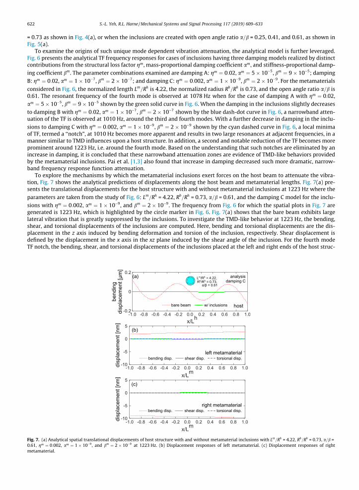
To explore the mechanisms by which the metamaterial inclusions exert forces on the host beam to attenuate the vibra-tion, Fig. 7 shows the analytical predictions of displacements along the host beam and metamaterial lengths. Fig. 7(a) pre-sents the translational displacements for the host structure with and without metamaterial inclusions at 1223 Hz where the
parameters are taken from the study of Fig. 6: Lm=Rh = 4.22, Rb=Rh = 0.73, a=b = 0.61, and the damping C model for the inclu-sions with gm ¼ 0:002, am ¼ 1� 10�9, and bm ¼ 2� 10�9. The frequency from Fig. 6 for which the spatial plots in Fig. 7 aregenerated is 1223 Hz, which is highlighted by the circle marker in Fig. 6. Fig. 7(a) shows that the bare beam exhibits largelateral vibration that is greatly suppressed by the inclusions. To investigate the TMD-like behavior at 1223 Hz, the bending,shear, and torsional displacements of the inclusions are computed. Here, bending and torsional displacements are the dis-placement in the z axis induced by bending deformation and torsion of the inclusion, respectively. Shear displacement isdefined by the displacement in the x axis in the xz plane induced by the shear angle of the inclusion. For the fourth modeTF notch, the bending, shear, and torsional displacements of the inclusions placed at the left and right ends of the host struc-
Fig. 7. (a) Analytical spatial translational displacements of host structure with and without metamaterial inclusions with Lm=Rh = 4.22, Rb=Rh = 0.73, a=b =0.61, gm ¼ 0:002, am ¼ 1� 10�9, and bm ¼ 2� 10�9 at 1223 Hz. (b) Displacement responses of left metamaterial. (c) Displacement responses of rightmetamaterial.

S.-L. Yeh, R.L. Harne /Mechanical Systems and Signal Processing 117 (2019) 609–633 623
ture are shown in Fig. 7(b) and (c), respectively. The inclusions have greater translational (i.e. bending) deformation thanshear and torsional deformations. In other words, the inclusions deliver an anti-phase lateral force to attenuate the motionof the host structure. It can be concluded that the TMD behavior at 1223 Hz is induced by bending deformations of the inclu-sions, encouraging a term ‘‘bending TMD behavior”.
The inclusion deformations are shown at 1010 Hz, i.e. around the third and fourth modes of the host beam, in Fig. 8 for thecase of inclusion damping model C using gm ¼ 0:002, am ¼ 1� 10�9, and bm ¼ 2� 10�9. This frequency is highlighted in Fig. 6by the square marker. In Fig. 8, it is seen that the inclusions undergo greater shear deformations in comparison to the trans-lational and torsional deformations. In other words, for the TMD behavior around the third and fourth modes, the cross-sections of the inclusions rotate in the y-axis, in a way to rock back-and-forth to attenuate the beam vibration. It can be con-cluded that the TMD behavior at 1010 Hz is induced by shear deformations of the inclusions, encouraging the term a ‘‘shearTMD behavior”.
The bending and shear deformations are analogous to two degrees-of-freedom. As a result, the metamaterial inclusionsstudied in this research may be conceptualized as two-degree-of-freedom TMDs according to the distinct ways by whichthey interact with the host structure. In other words, one metamaterial inclusion achieves a combination of influences com-parable to a two-degree-of-freedom TMD. Consequently, this study reveals that multiple interactions mechanisms of themetamaterial inclusions may enhance the versatility of vibration attenuation using fewer attached treatments.
5.6. Adaptation of shear TMD vibration attenuation phenomena
The results of Section 5.5 indicate that the metamaterials exhibit multiple TMD-like mechanisms by which to control thehost beam vibration. To uncover strategies to tailor the working frequency range for the shear TMD phenomena, Fig. 9(a)presents the analytical TF frequency response of the host beamwith the metamaterial inclusions for three values of the openangle ratio of the radially arrayed beams, a=b = 0.25, 0.50, and 0.75. For the metamaterials considered in Fig. 9(a), the nor-
malized length Lm=Rh is 4.22, the normalized radius of the core bulk metamaterial inclusion Rb=Rh is 0.50, and the inclusiondamping coefficients are gm ¼ 0:02, am ¼ 1� 10�7, and bm ¼ 2� 10�7. Additional parameters used in the analysis for theresults of Fig. 9 are reported in Table 2.
In Fig. 9(a), one observes a first notch, around the third and fourth modes, at 912 Hz for a=b = 0.25. As the open angle ratiois varied to a=b = 0.50 the notch shifts downwards to 907 Hz and still further downwards to 876 Hz for a=b = 0.75. Assessingthe influences on the inclusion geometry with the parameter chance, for increase in the open angle ratio a=b the total inclu-sion mass reduces while the overall dynamic stiffness of the porous metamaterial layer decreases. Stiffness reduction (with-out mass change) reduces the frequency of a TMD behavior, whereas mass reduction (without stiffness change) increases thefrequency of a TMD behavior. Based on the trends of decreasing notch frequency by increasing the open angle ratio a=b, it isapparent that the most influential aspect of tailoring the open angle ratio of the inclusions is to change the dynamic stiffnessof the overall porous layer and thus result in a decrease of the notch frequency.
Fig. 9(b) presents the analytical TF frequency responses of the host beam with the metamaterial inclusions when the nor-
malized radius of the core bulk metamaterial inclusion is either Rb=Rh = 0.25, 0.50, or 0.75. For the metamaterials considered
in Fig. 9(b), the normalized length Lm=Rh is 4.22, the open angle ratio of the radially arrayed beams a=b is 0.25, and the inclu-sion damping coefficients are gm ¼ 0:02, am ¼ 1� 10�7, and bm ¼ 2� 10�7. In Fig. 9(b), one observes how change of the nor-malized radius of the central core layer of the metamaterial inclusion tailors the significance of the TMD behaviors. For
Fig. 8. (a) Analytical displacement responses of left metamaterial. (b) Displacement responses of right metamaterial. Results at frequency 1010 Hz.Parameters used are Lm=Rh = 4.22, Rb=Rh = 0.73, a=b = 0.61, gm ¼ 0:002, am ¼ 1� 10�9, and bm ¼ 2� 10�9.

Fig. 9. (a) Analytical TF frequency responses of host beam with the inclusions with three values for open angle ratio, a=b= 0.25, 0.50, and 0.75. The lengthLm=Rh is 4.22, and the radius ratio Rb=Rh is 0.50. (b) Analytical TF frequency responses of host beam with the inclusions with three values for radius ratioRb=Rh is 0.25, 0.50, and 0.75. The length Lm=Rh is 4.22, and the open angle ratio a=b is 0.25.
624 S.-L. Yeh, R.L. Harne /Mechanical Systems and Signal Processing 117 (2019) 609–633
instance, a first notch occurs around the third and fourth modes at 902 Hz for Rb=Rh = 0.25, then shifts upwards to 912 Hz for
Rb=Rh = 0.50, and shifts further to higher frequencies around 1027 Hz for Rb=Rh = 0.75. The increase in the normalized radius
Rb=Rh of the core layer of the metamaterial inclusion results in an increase in the dynamic mass yet also reduces the length ofthe radially arrayed beams without changing the beam thickness. The latter influence thus increases the overall dynamicstiffness of the porous metamaterial layer. The results of Fig. 9(b) suggest that the increase in the normalized radius
Rb=Rh leads to an increase in the notch frequency. Consequently, the change of the normalized radius Rb=Rh, all other meta-material inclusion parameters remaining the same, is more influential to change the overall stiffness of the inclusions than tochange the dynamic mass.
Generally, shear deformation is more influential for thick beams than for slender beams. When the open angle ratio a=breduces, the radially arrayed beams become thicker (i.e. reduced slenderness) so as to increase the amplitude of shear dis-
placement. When the normalized radius Rb=Rh increases, the radially arrayed beams also become less slender. These param-
eter changes using a=b and Rb=Rh help to govern the activation of the shear TMD effect.
5.7. Adaptation of bending TMD vibration attenuation phenomena
As shown through the results of Fig. 7, at frequencies around fourth mode of the host structure the primary deformationof the inclusions is lateral translation associated with relative displacement between the bulk metamaterial layer and hoststructure. Small changes in such bending TMD effect are observed through the shifting of the notch in Fig. 9(a) and (b)
according to change in the parameters of open angle ratio a=b and the radius ratio Rb=Rh. Yet, change in other design param-eters may be more influential to tailor the dynamics associated with the bending TMD behavior.
To investigate the parameter that may greatly influence the existence of such bending TMD effects, Fig. 10 presents theanalytical TF frequency responses of the host beam with the metamaterial inclusions for three values of Young’s modulus,
Fig. 10. Analytical TF frequency responses of host beam with the inclusions with three values for Young’s modulus, Em= 150 MPa, 752 MPa, and 3760 MPa.The length Lm=Rh is 4.22, the radius ratio Rb=Rh is 0.22, and the open angle ratio a=b is 0.61.

S.-L. Yeh, R.L. Harne /Mechanical Systems and Signal Processing 117 (2019) 609–633 625
Em = 150 MPa, 752 MPa, and 3760 MPa. For the metamaterials considered in Fig. 10, the normalized length Lm=Rh is 4.22, the
normalized radius of the core bulk metamaterial inclusion Rb=Rh is 0.22, the open angle ratio of the radially arrayed beamsa=b is 0.61, and the inclusion damping coefficients are from the damping model B using gm ¼ 0:02, am ¼ 1� 10�7, andbm ¼ 2� 10�7.
As seen in Fig. 10, for an increase of the Young’s modulus of the inclusions, the resonant frequency at which the bendingTMD behavior occurs increases. In Figs. 3(e), 4(e), and 5(e), the frequency shifts for the fourth, fifth, and sixth modes are seento be less than the frequency shifts induced for the three lowest order modes. For the metamaterials considered in Figs. 3–5,the bending TMD effects all occur at the frequencies around the third and the fourth modes since the Young’s modulus valuesare the same for all of the results presented in Figs. 3–5. Consequently, it is apparent that the smaller frequency shifts of thehigher modes are associated with frequencies greater than the bending TMD behavior. In Fig. 10, for the metamaterial inclu-sions with Young’s modulus Em = 150 MPa, the resonant frequency of the bending TMD is at the frequency around the secondand third mode, in the frequency range around 400–600 Hz. For this selection of the Young’s modulus, the modal frequencyshifts are less from the third mode and above, than for the first and second modes. For the case of the metamaterial inclu-sions with Young’s modulus Em = 3760 MPa in Fig. 10, the resonant frequency of bending TMD is around the fifth and sixthmodes, in the frequency range from around 1900 to 3000 Hz. Consequently, the reduced shifts of the modal resonant fre-quencies are apparent for modes greater than the sixth mode. These results reveal that the significance of the resonant fre-quency shifts is associated with the frequencies around which the bending TMD behaviors occur. At frequencies greater thanthis range, the resonant frequency shifts are significantly reduced.
6. Conclusions
This research establishes and experimentally validates an analytical modeling framework to elucidate the working mech-anisms of broadband vibration attenuation realized by elastomeric metamaterial inclusions within host cylindrical struc-tures. Leveraging the analysis reveals a wealth of non-intuitive insight on the specific ways by which the elastomericinclusions couple with the host structure. For instance, change in open angle ratio of the inclusion cross-section geometryand change in the central core mass diameter are primarily stiffness-tuning mechanisms although one may anticipate thatthe more visually apparent mass changes may be more influential. While the open angle ratio and radius ratio parametersare seen to slightly influence frequency range and depth of the notch-like vibration attenuation features, only change of theradius ratio influences bending TMD effects at higher frequencies. In addition, the Young’s modulus of the metamaterialinclusions is another means by which to dramatically shift the frequencies at which the bending TMD phenomena occur.Overall, this work uncovers the specific existence and adaptation mechanisms of two distinct TMD behaviors manifest bythe single metamaterial inclusion design, paving the way for future designs of broadband vibration mitigation materialsystems.
Acknowledgments
This work is supported by The Ohio State University Simulation Innovation and Modeling Center via Honda R&D Amer-icas, Inc.
Appendix A
A.1. Constants of area and area moment inertia
Ah ¼ p Rho
� �2� Rh� �2�
ðA:1Þ
Ab31 ¼ Ab
51 ¼ Ab52 ¼ p Rb
� �2ðA:2Þ
Ab57 ¼ 2p Rb
� �2ðA:3Þ
Aa30 ¼ p
6 Rh � Rb� �2
6 Rb� �2
Rh� �2
� Rpð Þ2�
�8Rb Rh� �3
� Rpð Þ3�
þ 3 Rh� �4
� Rpð Þ4�
8>>><>>>:
9>>>=>>>;
ðA:4Þ

626 S.-L. Yeh, R.L. Harne /Mechanical Systems and Signal Processing 117 (2019) 609–633
Aa31 ¼ p
6 Rh � Rb� �2 Rh � Rp
� �3Rh þ 3Rp� �
ðA:5Þ
Aa34 ¼
p Rh � Rp� �2
3 Rh � Rb� �2 Rh
� �2þ 2 Rh
� �Rpð Þ þ 3 Rpð Þ2 � 2 Rb
� �Rh þ 2Rp� ��
ðA:6Þ
Aa50 ¼
3p Rh� �4
� Rpð Þ4�
16 Rh � Rb� �2 ðA:7Þ
Aa51 ¼
p Rh � Rp� �3
Rh þ 3Rp� �
6 Rh � Rb� �2 ðA:8Þ
Aa52 ¼ p
16 Rh � Rb� �2 3 Rh
� �4� 16 Rh
� �2Rpð Þ2 þ 32Rh Rpð Þ3 � 19 Rpð Þ4
� ðA:9Þ
Aa54 ¼ p
6 Rh � Rb� �2 Rh
� �4� 4Rh Rpð Þ3 þ 3 Rpð Þ4
� ðA:10Þ
Aa55 ¼ p
24 Rh � Rb� �2 5 Rh
� �4þ 16Rh Rpð Þ3 � 21 Rpð Þ4
� ðA:11Þ
Aa57 ¼ �
p Rh � Rp� �2
6 Rh � Rb� �2 Rh
� �2þ 2RhRp � 9 Rpð Þ2
� ðA:12Þ
Aa60 ¼ Aa
62 ¼p Rh� �4
� Rpð Þ4�
16 Rh � Rb� �2 ðA:13Þ
Aa65 ¼
p Rh� �4
� Rpð Þ4�
8 Rh � Rb� �2 ¼ 2Aa
60 ðA:14Þ
Ap23 ¼ Ap
33 ¼Rb� �4
� Rpð Þ4
128 Rh � Rb� �2 H21 ðA:15Þ
Ap30 ¼ H0
12 Rh � Rb� �2 Rb � Rp
� �3Rb þ 3Rp� �
ðA:16Þ
Ap31 ¼ H0
12 Rh � Rb� �2 3 Rb
� �4� 8 Rb
� �3Rh� �
þ 6 Rb� �2
Rh� �2
�3 Rpð Þ4 þ 8 Rpð Þ3 Rh� �
� 6 Rpð Þ2 Rh� �2
264
375 ðA:17Þ
Ap34 ¼
H0 Rb � Rp� �2
6 Rh � Rb� �2 Rb
� �2� 2 Rb
� �Rh� �
þ 2 Rb� �
Rpð Þ � 4 Rh� �
Rpð Þ þ 3 Rpð Þ2�
ðA:18Þ

S.-L. Yeh, R.L. Harne /Mechanical Systems and Signal Processing 117 (2019) 609–633 627
Ap43 ¼
Rb� �4
� Rpð Þ4
32 Rb � Rh� �2 H22 ðA:19Þ
Ap50 ¼
Rb� �4
� Rpð Þ4
128 Rh � Rb� �2 H8 ðA:20Þ
Ap51 ¼ H0
12 Rh � Rb� �2
3 Rb� �4
� 8 Rb� �3
Rh� �
þ 6 Rb� �2
Rh� �2
þ Rpð Þ2 �6 Rh� �2
þ 8 Rpð Þ Rh� �
� 3 Rpð Þ2�
8>><>>:
9>>=>>; ðA:21Þ
Ap52 ¼ 1
384 Rh � Rb� �2
12 Rb � Rp� � 19 Rb
� �3þ Rpð Þ2 �32Rh þ 19Rb
� �þ Rb þ Rp� �
16 Rh� �2
� 32 Rh� �
Rb� �
þ 19 Rb� �2�
2664
3775H0
�8 9 Rb� �4
� 8 Rb� �3
Rh� �
þ 8Rh � 9Rp� �
Rpð Þ3�
H62
þ3 Rb� �4
� Rpð Þ4�
H63
8>>>>>>>>>>><>>>>>>>>>>>:
9>>>>>>>>>>>=>>>>>>>>>>>;
ðA:22Þ
Ap54 ¼ � H11
12 Rh � Rb� �2 3 Rb
� �4� 4 Rb
� �3Rh� �
þ 4Rh � 3Rp� �
Rpð Þ3�
ðA:23Þ
Ap55 ¼ 1
192 Rh � Rb� �2 � Rb
� �364 Rh� �
H11 þ 3 Rb� �
H4
h iþ Rpð Þ3 64 Rh
� �H11 þ 3 Rpð ÞH4
h i �ðA:24Þ
Ap57 ¼ 1
24 Rh � Rb� �2
�2 Rb� �2
9 Rb� �2
� 20 Rb� �
Rh� �
þ 12 Rh� �2�
H0
þ2 Rpð Þ2 12 Rh� �2
� 20 Rh� �
Rpð Þ þ 9 Rpð Þ2�
H0
þ Rb� �3
3Rb � 4Rh� �
H62
� Rpð Þ3 �4Rh þ 3Rp� �
H62
8>>>>>>>>>><>>>>>>>>>>:
9>>>>>>>>>>=>>>>>>>>>>;
ðA:25Þ
Ap60 ¼ Ap
62 ¼Rb� �4
� Rpð Þ4
128 Rh � Rb� �2 H21 ðA:26Þ
Ap65 ¼
Rb� �4
� Rpð Þ4
64 Rh � Rb� �2 H21 ¼ 2Ap
60 ðA:27Þ
Ih ¼ p4
Rho
� �4� Rh� �4�
ðA:28Þ
Ib12 ¼ Ib23 ¼ Ib33 ¼ p4
Rb� �4
ðA:29Þ
Ia10 ¼ p
Rh � Rb� �2 Rb
� �24
Rh� �4
� Rpð Þ4�
� 2Rb
5Rh� �5
� Rpð Þ5�
þ 16
Rh� �6
� Rpð Þ6� 8><
>:9>=>; ðA:30Þ

628 S.-L. Yeh, R.L. Harne /Mechanical Systems and Signal Processing 117 (2019) 609–633
Ia12 ¼ p
60 Rh � Rb� �2 Rh
� �6� 15 Rh
� �2Rpð Þ4 þ 24Rh Rpð Þ5 � 10 Rpð Þ6
� ðA:31Þ
Ia15 ¼ p
30 Rh � Rb� �2 Rh
� �5�3Rb þ 2Rh� �
þ 15RbRh Rpð Þ4
�12 Rb þ Rh� �
Rpð Þ5 þ 10 Rpð Þ6
264
375 ðA:32Þ
Ia30 ¼ Ia31 ¼p Rh� �2
� Rpð Þ2�
2 Rh � Rb� �2 ðA:33Þ
Ia34 ¼p Rh� �2
� Rpð Þ2�
Rh � Rb� �2 ¼ 2Ia30 ðA:34Þ
Ip10 ¼ H11
120 Rh � Rb� �2 Rb
� �6� 15 Rb
� �2Rpð Þ4 þ 24 Rb
� �Rpð Þ5 � 10 Rpð Þ6
� ðA:35Þ
Ip12 ¼ Ip23 ¼ H11
120 Rh � Rb� �2
10 Rb� �6
� 24 Rb� �5
Rh� �
þ 15 Rb� �4
Rh� �2
þ Rpð Þ4 �15 Rh� �2
þ 24 Rh� �
Rpð Þ � 10 Rpð Þ2�
8>><>>:
9>>=>>; ðA:36Þ
Ip15 ¼ H11
60 Rh � Rb� �2 Rb
� �52Rb � 3Rh� �
þ 15 Rb� �
Rh� �
Rpð Þ4
�12 Rb þ Rh� �
Rpð Þ5 þ 10 Rpð Þ6
264
375 ðA:37Þ
Ip30 ¼ Ip31 ¼Rb� �2
� Rpð Þ2
4 Rh � Rb� �2 H11 ðA:38Þ
Ip33 ¼ H12
120 Rh � Rb� �2
10 Rb� �6
� 24 Rb� �5
Rh� �
þ 15 Rb� �4
Rh� �2
þ Rpð Þ4 �15 Rh� �2
þ 24 Rh� �
Rpð Þ � 10 Rpð Þ2�
8>><>>:
9>>=>>; ðA:39Þ
Ip34 ¼Rb� �2
� Rpð Þ2
2 Rh � Rb� �2 H11 ¼ 2Ip30 ðA:40Þ
Ip36 ¼ H61
30 Rh � Rb� �2 Rb
� �43Rb � 5Rh� �
þ 20 Rb� �
Rh� �
Rpð Þ3
�15 Rb þ Rh� �
Rpð Þ4 þ 12 Rpð Þ5
8><>:
9>=>; ðA:41Þ
Ip38 ¼ H61
15 Rh � Rb� �2
6 Rb� �5
� 15 Rb� �4
Rh� �
þ 10 Rb� �3
Rh� �2
þ Rpð Þ3 �10 Rh� �2
þ 15 Rh� �
Rpð Þ � 6 Rpð Þ2�
8>><>>:
9>>=>>; ðA:42Þ
Jb53 ¼ Jb63 ¼ p4
Rb� �4
ðA:43Þ
S.-L. Yeh, R.L. Harne /Mechanical Systems and Signal Processing 117 (2019) 609–633 629
Ja40 ¼ Ja41 ¼p Rh� �2
� Rpð Þ2�
2 Rh � Rb� �2 ðA:44Þ
Ja44 ¼p Rh� �2
� Rpð Þ2�
Rh � Rb� �2 ¼ 2Ja40 ðA:45Þ
Jp36 ¼ Jp38 ¼2 Rb� �3
� Rpð Þ3�
9 Rh � Rb� �2 H3 ðA:46Þ
Jp40 ¼ Jp41 ¼Rb� �2
� Rpð Þ2
4 Rh � Rb� �2 H12 ðA:47Þ
Jp44 ¼Rb� �2
� Rpð Þ2
2 Rh � Rb� �2 H12 ¼ 2Jp40 ðA:48Þ
Jp46 ¼ Jp48 ¼ �Rb� �3
� Rpð Þ3
9 Rh � Rb� �2 H7 ðA:49Þ
Jp53 ¼ H12
120 Rh � Rb� �2
10 Rb� �6
� 24 Rb� �5
Rh� �
þ 15 Rb� �4
Rh� �2
þ Rpð Þ4 �15 Rh� �2
þ 24 Rh� �
Rpð Þ � 10 Rpð Þ2�
8>><>>:
9>>=>>; ðA:50Þ
Jp56 ¼ � H3
30 Rh � Rb� �2 4 Rb
� �5� 5 Rb
� �4Rh þ 5Rh � 4Rp
� �Rpð Þ4
� ðA:51Þ
Jp58 ¼ H61
15 Rh � Rb� �2
6 Rb� �5
� 15 Rb� �4
Rh� �
þ 10 Rb� �3
Rh� �2
þ Rpð Þ3 �10 Rh� �2
þ 15 Rh� �
Rpð Þ � 6 Rpð Þ2�
8>><>>:
9>>=>>; ðA:52Þ
Jp59 ¼ H61
60 Rh � Rb� �2
� Rb� �3
32 Rb� �2
� 70 Rb� �
Rh� �
þ 40 Rh� �2
þ Rb �4Rb þ 5Rh� �
H5
�
þ Rpð Þ3 40 Rh� �2
� 70 Rh� �
Rpð Þ þ 32 Rpð Þ2 þ 5Rh � 4Rp� �
RpH5
� 8>>><>>>:
9>>>=>>>;
ðA:53Þ
Jp63 ¼ H11
120 Rh � Rb� �2
10 Rb� �6
� 24 Rb� �5
Rh� �
þ 15 Rb� �4
Rh� �2
þ Rpð Þ4 �15 Rh� �2
þ 24 Rh� �
Rpð Þ � 10 Rpð Þ2�
2664
3775 ðA:54Þ
Jp66 ¼ Jp69 ¼ � H3
30 Rh � Rb� �2 4 Rb
� �5� 5 Rb
� �4Rh� �
þ 5Rh � 4Rp� �
Rpð Þ4�
ðA:55Þ
H0 ¼XNn¼1
h1n � h2nð Þ ðA:56Þ

630 S.-L. Yeh, R.L. Harne /Mechanical Systems and Signal Processing 117 (2019) 609–633
H11 ¼XNn¼1
h1n � h2n � sinh1ncosh1n þ sinh2ncosh2nð Þ ðA:57Þ
H12 ¼XNn¼1
h1n � h2n þ sinh1ncosh1n � sinh2ncosh2nð Þ ðA:58Þ
H21 ¼XNn¼1
4h1n � 4h2n � sin4h1n þ sin4h2nð Þ ðA:59Þ
H22 ¼XNn¼1
4h1n � 4h2n þ sin4h1n � sin4h2nð Þ ðA:60Þ
H3 ¼XNn¼1
sin3h1n � sin3h2n� �
ðA:61Þ
H4 ¼XNn¼1
28 �h1n þ h2nð Þ þ 16 sin2h1n � sin2h2nð Þ � sin4h1n þ sin4h2n½ � ðA:62Þ
H5 ¼XNn¼1
cos2h1n þ cos2h2n � 2sinh1nsinh2nð Þ ðA:63Þ
H61 ¼XNn¼1
sinh1n � sinh2nð Þ ðA:64Þ
H62 ¼XNn¼1
sin2h1n � sin2h2nð Þ ðA:65Þ
H63 ¼XNn¼1
sin4h1n � sin4h2nð Þ ðA:66Þ
H7 ¼XNn¼1
3sinh1n þ sin3h1n � 3sinh2n � sin3h2nð Þ ðA:67Þ
H8 ¼XNn¼1
12h1n � 12h2n � 8sin2h1n þ sin4h1n þ 8sin2h2n � sin4h2nð Þ ðA:68Þ
A.2 Components of mass and stiffness matrix and force vector
Mhbhbfp ¼ 2qhIh
L
Z 1
�1/hb0
p /hb0f dnþ qhAhL
2
Z 1
�1/hb
p /hbf dn
þ 2qm Ia10 þ Ip10� �Lm
Z 1
�1/hb0
p /hb0f dnm þ qm Aa
30 þ Ap30
� �Lm
2
Z 1
�1/hb
p /hbf dnm
ðA:69Þ
Mhbmbfq ¼ qm Aa
34 þ Ap34
� �Lm
4
Z 1
�1/hb
f /mbq dnm ðA:70Þ
Mhbmsfr ¼ qm Ia15 þ Ip15
� �2
Z 1
�1/hb0
f /msr dnm ðA:71Þ
Mhbmtfs ¼ qmIp36L
m
4
Z 1
�1/hb
f /mts dnm ðA:72Þ
S.-L. Yeh, R.L. Harne /Mechanical Systems and Signal Processing 117 (2019) 609–633 631
Mmbmbgq ¼
qm Ab31 þ Aa
31 þ Ap31
� �Lm
2
Z 1
�1/mb
q /mbg dnm ðA:73Þ
Mmbmsgr ¼ 0 ðA:74Þ
Mmbmtgs ¼ qmIp38L
m
4
Z 1
�1/mb
g /mts dnm ðA:75Þ
Mmsmshr ¼
qm Ib12 þ Ia12 þ Ip12� �
Lm
2
Z 1
�1/ms
r /msh dnm ðA:76Þ
Mmsmths ¼ 0 ðA:77Þ
Mmtmtis ¼
qm Ib23 þ Ib33 þ Ip23 þ Ip33� �
Lm
2
Z 1
�1/mt
s /mti dnm ðA:78Þ
Khbhbfp ¼ 8E
�hIh
L3
Z 1
�1/hb00
p /hb00f dnþ 8E
�m Ia10 þ Ip10� �Lmð Þ3
Z 1
�1/hb00
p /hb00f dnm
þ2G�m ka Aa
50 þ Aa60
� �þ kp Ap50 þ Ap
60
� �� Lm
Z 1
�1/hb0
p /hb0f dnm
þ E�m Ia30 þ Ip30� �
Lm þ G�m kaJa40 þ kpJp40� �
Lm
2
Z 1
�1/hb
p /hbf dnm
ðA:79Þ
Khbmbfq ¼ �G
�m kaAa
54 þ kpAp54
� �Lm
Z 1
�1/hb0
f /mb0q dnm
�E�m Ia34 þ Ip34� �
Lm þ G�m kaJa44 þ kpJp44� �
Lm
4
Z 1
�1/mb
q /hbf dnm
ðA:80Þ
Khbmsfr ¼ 2E
�m Ia15 þ Ip15� �Lmð Þ2
Z 1
�1/hb00
f /ms0r dnm
�G�m ka Aa
55 þ Aa65
� �þ kp Ap55 þ Ap
65
� �� 2
Z 1
�1/hb0
f /msr dnm
ðA:81Þ
Khbmtfs ¼ �G
�mkp Jp56 � Jp66� �Lm
Z 1
�1/hb0
f /mt0s dnm �
E�mJp36 � G
�mkpJp46
� �Lm
4
Z 1
�1/hb
f /mts dnm ðA:82Þ
Kmbmbgq ¼
2G�m kbAb
51 þ kaAa51 þ kpAp
51
� �Lm
Z 1
�1/mb0
q /mb0g dnm
þE�m Ia31 þ Ip31� �
Lm þ G�m kaJa41 þ kpJp41� �
Lm
2
Z 1
�1/mb
q /mbg dnm
ðA:83Þ
Kmbmsgr ¼ �
G�m kbAb
57 � kaAa57 � kpAp
57
� �2
Z 1
�1/mb0
g /msr dnm ðA:84Þ
Kmbmtgs ¼ G
�mkpJp58Lm
Z 1
�1/mb0
g /mt0s dnm þ
E�mJp38 � G
�mkpJp48
� �Lm
4
Z 1
�1/mb
g /mts dnm ðA:85Þ

632 S.-L. Yeh, R.L. Harne /Mechanical Systems and Signal Processing 117 (2019) 609–633
Kmsmshr ¼
2E�m Ib12 þ Ia12 þ Ip12� �
Lm
Z 1
�1/ms0
r /ms0h dnm
þG�m kbAb
52 þ ka Aa52 þ Aa
62
� �þ kp Ap52 þ Ap
62
� �h iLm
2
Z 1
�1/ms
r /msh dnm
ðA:86Þ
Kmsmths ¼ �G
�mkp Jp69 � Jp59
� �2
Z 1
�1/ms
h /mt0s dnm ðA:87Þ
Kmtmtis ¼
2G�m kb Jb53 þ Jb63
� �þ kp Jp53 þ Jp63
� �h iLm
Z 1
�1/mt0
s /mt0i dnm
þE�m Ap
23 þ Ap33
� �þ G�mkpAp
43
� Lm
2
Z 1
�1/mt
s /mti dnm
ðA:88Þ
Fhbf ¼ L
2
Z 1
�1F/hb
f dn ðA:89Þ
References
[1] P.F. Pai, Metamaterial-based broadband elastic wave absorber, J. Intell. Mater. Syst. Struct. 21 (5) (2010) 517–528.[2] H. Sun, X. Du, P.F. Pai, Theory of metamaterial beams for broadband vibration absorption, J. Intell. Mater. Syst. Struct. 21 (11) (2010) 1085–1101.[3] P.F. Pai, H. Peng, S. Jiang, Acoustic metamaterial beams beased on multi-frequency vibration absorbers, Int. J. Mech. Sci. 79 (2014) 195–205.[4] P. Wang, F. Casadei, S. Shan, J.C. Weaver, K. Bertoldi, Harnessing buckling to design tunable locally resonant acoustic metamaterials, Phys. Rev. Lett. 113
(2014) 014301.[5] K.H. Matlack, A. Bauhofer, S. Krödel, A. Palermo, C. Daraio, Composite 3D-printed metastructures for low-frequency and broadband vibration
absorption, Proc. Natl. Acad. Sci. 113 (30) (2016) 8386–8390.[6] M. Nouh, O. Aldraihem, A. Baz, Wave propagation in metamaterial plates with periodic local resonances, J. Sound Vib. 341 (2015) 53–73.[7] J.H. Oh, S. Qi, Y.Y. Kim, B. Assouar, Elastic metamaterial insulator for broadband low-frequency flexural vibration shielding, Phys. Rev. Appl 8 (5) (2017)
054034.[8] X.N. Liu, G.K. Hu, C.T. Sun, G.L. Huang, Wave propagation characterization and design of two-dimensional elastic chiral metacomposite, J. Sound Vib.
330 (2011) 2536–2553.[9] R. Zhu, X.N. Liu, G.K. Hu, C.T. Sun, G.L. Huang, A chiral elastic metamateiral beam for broadband vibration suppression, J. Sound Vib. 333 (2014) 2759–
2773.[10] E. Baravelli, M. Ruzzene, Internally resonating lattices for bandgap generation and low-frequency vibration control, J. Sound Vib. 332 (2013) 6562–
6579.[11] O. Abdeljaber, O. Avci, D.J. Inman, Optimization of chiral lattice based metastructures for broadband vibration suppression using genetic algorithms, J.
Sound Vib. 369 (2016) 50–62.[12] P. Aumjaud, C.W. Smith, K.E. Evans, A novel viscoelastic damping treatment for honeycomb sandwich structures, Compos. Struct. 119 (2015) 322–332.[13] Y.C. Chen, S.C. Huang, An optimal placement of CLD treatment for vibration suppression of plates, Int. J. Mech. Sci. 44 (8) (2002) 1801–1821.[14] J.L. Marcelin, P. Trompette, A. Smati, Optimal constrained layer damping with partial coverage, Finite Elem. Anal. Des. 12 (3–4) (1992) 273–280.[15] H. Zheng, C. Cai, X.M. Tan, Optimization of partial constrained layer damping treatment for vibrational energy minimization of vibrating beams,
Comput. Struct. 82 (29–30) (2004) 2493–2507.[16] H. Zheng, C. Cai, G.S.H. Pau, G.R. Liu, Minimizing vibration response of cylindrical shells through layout optimization of passive constrained layer
damping treatments, J. Sound Vib. 279 (739–756) (2005) 3–5.[17] H. Zheng, G.S.H. Pau, Y.Y. Wang, A comparative study on optimization of constrained layer damping treatment for structural vibration control, Thin-
Wall. Struct. 44 (8) (2006) 886–896.[18] S.A. Nayfeh, Damping of flexural vibration in the plane of lamination of elastic–viscoelastic sandwich beams, J. Sound Vib. 276 (3–5) (2004) 689–711.[19] J. Plattenburg, J.T. Dreyer, R. Singh, A new analytical model for vibration of a cylindrical shell and cardboard liner with focus on interfacial distributed
damping, Mech. Syst. Sig. Process. 75 (2016) 176–195.[20] J. Plattenburg, J.T. Dreyer, R. Singh, Vibration control of a cylindrical shell with concurrent active piezoelectric patches and passive cardboard liner,
Mech. Syst. Sig. Process. 91 (2017) 422–437.[21] B.E. Douglas, J.C.S. Yang, Transverse compressional damping in the vibratory response of elastic-viscoelastic-elastic beams, AIAA J. 16 (9) (1978) 925–
930.[22] E.M. Kerwin Jr., Damping of flexural waves by a constrained viscoelastic layer, J. Acoust. Soc. Am. 31 (7) (1959) 952–962.[23] J. Bishop, Q. Dai, Y. Song, R.L. Harne, Resilience to impact by extreme energy absorption in lightweight material inclusions constrained near a critical
point, Adv. Eng. Mater. 18 (2016) 1871–1876.[24] R.L. Harne, Y. Song, Q. Dai, Trapping and attenuating broadband vibroacoustic energy with hyperdamping metamaterials, Extreme Mech. Lett. 12
(2017) 41–47.[25] O. Beslin, J. Nicolas, A hierarchical functions set for predicting very high order plate bending modes with any boundary conditions, J. Sound Vib. 202 (5)
(1997) 633–655.[26] L. Dozio, On the use of the trigonometric Ritz method for general vibration analysis of rectangular Kirchhoff plates, Thin-Wall. Struct. 49 (1) (2011)
129–144.[27] J.E. Ruzicka, Damping structural resonances using viscoelastic shear-damping mechanisms, part i: design configurations, J. Eng. Ind. 83 (1961) 403–
413.[28] P.J. Torvik, The analysis and design of constrained layer damping treatments, Air Force Institute of Technology Wright-Patterson AFB, Ohio, USA, 1980
(Technical Report AFIT TR 80-4).[29] G.R. Cowper, The shear coefficient in Timoshenko’s beam theory, J. Appl. Mech. 33 (2) (1966) 335–340.[30] S.S. Rao, Vibration of Continuous Systems, John Wiley & Sons Inc, Hoboken, New Jersey, 2007.

S.-L. Yeh, R.L. Harne /Mechanical Systems and Signal Processing 117 (2019) 609–633 633
[31] C.G. Cooley, T.Q. Tran, T. Chai, Comparison of viscous and structural damping models for piezoelectric vibration energy harvesters, Mech. Syst. Sig.Process. 110 (2018) 130–138.
[32] N. Kumar, S.P. Singh, Vibration control of curved panel using smart damping, Mech. Syst. Sig. Process. 30 (2012) 232–247.