mechanical specifications - lcsconstruct.com · mechanical specifications . section #'s...
TRANSCRIPT

Mechanical Specifications Section #'s Section Title 15050 Basic Mechanical Materials and Methods 15060 Hangers and Supports 15100 Valves 15411 Water Distribution Piping 15420 Drainage and Vent Piping 15440 Plumbing fixtures 15496 Natural Gas Piping 15521 Sliding Balancer Track Vehicle Exhaust Removal System 15815 Metal Ducts 15820 Duct Accessories 15830 Variable Refrigerant Flow System 15853 Power Ventilators 15855 Diffusers, Registers and Grilles 15990 Testing Adjusting and Balancing

BASIC MECHANICAL MATERIALS AND METHODS 15050 - 1
SECTION 15050 - BASIC MECHANICAL MATERIALS AND METHODS
1.1 GENERAL
A. Definitions include the following:
1. Finished Spaces: Spaces other than mechanical and electrical equipment rooms, furred
spaces, pipe and duct shafts, unheated spaces immediately below roof, spaces above
ceilings, unexcavated spaces, crawl spaces, and tunnels.
2. Exposed, Interior Installations: Exposed to view indoors.
3. Exposed, Exterior Installations: Exposed to view outdoors, or subject to outdoor
ambient temperatures and weather conditions.
4. Concealed, Interior Installations: Concealed from view and protected from physical
contact by building occupants.
5. Concealed, Exterior Installations: Concealed from view and protected from weather
conditions and physical contact by building occupants, but subject to outdoor ambient
temperatures.
B. The following are industry abbreviations for plastic and rubber materials:
1. ABS: Acrylonitrile-butadiene-styrene plastic.
2. CPVC: Chlorinated polyvinyl chloride plastic.
3. NP: Nylon plastic.
4. PE: Polyethylene plastic.
5. PVC: Polyvinyl chloride plastic.
6. CR: Chlorosulfonated polyethylene synthetic rubber.
7. EPDM: Ethylene-propylene-diene terpolymer rubber.
C. Submit the following:
1. Product Data for dielectric fittings, flexible connectors, mechanical sleeve seals, and
identification materials and devices.
2. Shop Drawings for metal and wood supports and anchorage for mechanical materials and
equipment.
3. Coordination Drawings of major elements, components, and systems of mechanical
equipment.
4. Samples of color, lettering style, and other graphic representation required for each
identification material and device.
D. Equipment selection of higher electrical characteristics, physical dimensions, capacities, and
ratings may be furnished provided such proposed equipment is approved in writing and
connecting mechanical and electrical services, circuit breakers, conduit, motors, bases, and
equipment spaces are increased. Additional costs shall be approved in advance by appropriate
Contract Modification for these increases. If minimum energy ratings or efficiencies of
equipment are specified, equipment must meet design and commissioning requirements.
1.2 PRODUCTS

BASIC MECHANICAL MATERIALS AND METHODS 15050 - 2
A. Refer to individual Division 15 piping Sections for pipe and fitting materials and joining
methods and for special joining materials not listed below.
1. Pipe-Flange Gasket Materials: ASME B16.21, nonmetallic, flat, asbestos-free, suitable
for chemical and thermal conditions of piping system contents, and 1/8-inch maximum
thickness. Include full-face type for flat-face flanges, narrow-face type for raised-face
flanges, and carbon-steel bolts and nuts.
2. Plastic Pipe-Flange Gasket, Bolts, and Nuts: Type and material recommended by piping
system manufacturer.
3. Solder Filler Metal: ASTM B 32, Alloy Sn95, Alloy Sn94, or Alloy Sb5, unless
otherwise indicated.
4. Brazing Filler Metals: AWS A5.8, BCuP Series or Alloy BAg1, unless otherwise
indicated.
5. Welding Filler Metals: Comply with AWS D10.12.
6. Solvent Cements: ASTM D 2235 for ABS piping, ASTM F 493 for CPVC piping, and
ASTM D 2564 with ASTM F 656 primer for PVC piping.
B. Dielectric Fittings: Combination of copper alloy and ferrous; threaded, solder, plain, and weld-
neck end types matching piping system materials; with insulating material suitable for system
fluid, pressure, and temperature.
1. Dielectric Unions: Factory-fabricated, union assembly, for 250-psig minimum working
pressure at 180 deg F.
2. Dielectric Flanges: Factory-fabricated, companion-flange assembly, for 150- or 300-psig
minimum working pressure as required to suit system pressures.
3. Dielectric Couplings: Galvanized-steel coupling with inert and noncorrosive,
thermoplastic lining; threaded ends; and 300-psig minimum working pressure at 225
deg F .
4. Dielectric Nipples: Electroplated steel nipple with inert and noncorrosive, thermoplastic
lining; plain, threaded, or grooved ends; and 300-psig minimum working pressure at 225
deg F .
C. Flexible Connectors: Fabricated from materials suitable for system fluid and that will provide
flexible pipe connections. Include 125-psig minimum working-pressure rating, threaded ends
for 2-inch NPS and smaller, and flanged ends for 2-1/2-inch NPS and larger.
1. Bronze-Hose Type: Corrugated, bronze, inner tubing covered with bronze wire braid.
Include copper-tube ends or bronze flanged ends, braze welded to hose.
2. Stainless-Steel-Hose/Steel Pipe Type: Corrugated, stainless-steel, inner tubing covered
with stainless-steel wire braid. Include steel nipples or flanges, welded to hose.
3. Stainless-Steel-Hose/Stainless-Steel Pipe Type: Corrugated, stainless-steel, inner tubing
covered with stainless-steel wire braid. Include stainless-steel nipples or flanges, welded
to hose.
4. Rubber, Flexible Connectors: CR or EPDM elastomer rubber construction, with multiple
plies of NP fabric, molded and cured in hydraulic presses. Include 125-psig minimum
working-pressure rating at 220 deg F.

BASIC MECHANICAL MATERIALS AND METHODS 15050 - 3
D. Mechanical Sleeve Seals: Modular design, with interlocking rubber links shaped to
continuously fill annular space between pipe and sleeve. Include connecting bolts and pressure
plates.
E. Steel, Sheet-Metal Sleeves: 0.0239-inch minimum thickness, galvanized, round tube closed
with welded longitudinal joint.
F. Steel Pipe Sleeves: ASTM A 53, Type E, Grade A, Schedule 40, galvanized, plain ends.
G. Cast-Iron Wall Pipe: Cast or fabricated, and equivalent to ductile-iron pressure pipe, with plain
ends and integral waterstop.
H. PVC Sleeves: Manufactured, permanent, with nailing flange for attaching to wooden forms.
I. PVC Pipe Sleeves: ASTM D 1785, Schedule 40.
J. PE Sleeves: Manufactured, reusable, tapered, cup shaped, smooth outer surface, with nailing
flange for attaching to wooden forms.
K. Escutcheons: Manufactured wall, ceiling, and floor plates; deep-pattern type if required to
conceal protruding fittings and sleeves. Include ID to closely fit around pipe, tube, and
insulation of insulated piping and OD to completely cover opening.
1. Cast Brass: One-piece or split casting, with concealed hinge; set screw; and polished
chrome-plated finish.
2. Stamped Steel: Split plate, with concealed hinge, spring clips, and chrome-plated finish.
3. Stamped Steel: Split plate, with exposed-rivet hinge, spring clips, and chrome-plated
finish.
L. Identifying Devices and Labels: Manufacturer's standard products.
1. Equipment Nameplates: Metal nameplate with operational data engraved or stamped;
permanently fastened to equipment in accessible and visible location. Include
manufacturer, product name, model number, serial number, capacity, operating and
power characteristics, and labels of tested compliances.
2. Stencils: Standard stencils, prepared for required applications with letter sizes
complying with recommendations of ASME A13.1 for piping and similar applications,
but not less than 1-1/4-inch- high letters for ductwork and not less than 3/4-inch- high
letters for access door signs and similar operational instructions.
a. Material: Fiberboard or brass.
b. Stencil Paint: Standard exterior-type stenciling enamel; black, unless otherwise
indicated; either brushing grade or pressurized spray-can form and grade.
c. Identification Paint: Standard identification enamel of colors indicated or, if not
otherwise indicated for piping systems, comply with ASME A13.1 for colors.
3. Snap-on Plastic Pipe Markers: Manufacturer's standard preprinted, semirigid, snap on,
color-coded, complying with ASME A13.1.
4. Pressure-Sensitive Pipe Markers: Manufacturer's standard preprinted, permanent
adhesive, color-coded, pressure-sensitive vinyl, complying with ASME A13.1.

BASIC MECHANICAL MATERIALS AND METHODS 15050 - 4
5. Plastic Duct Markers: Manufacturer's standard color-coded, laminated plastic. Include
green for cold air; yellow for hot air; yellow/green or green for supply air; blue for
exhaust, outside, return, and mixed air; and as recommended by ASME A13.1 for
hazardous exhausts.
a. Nomenclature: Include direction of airflow; duct service, origin, and destination;
and design cubic feet per meter.
6. Engraved Plastic-Laminate Signs: ASTM D 709, Type I, cellulose, paper-base,
phenolic-resin-laminate engraving stock; Grade ES-2, black surface, black phenolic core,
with white melamine subcore. Fabricate in sizes required for message, engrave with
standard letter style, of sizes and with wording to match equipment identification, punch
for mechanical fastening, and 1/16-inch minimum thickness. Include self-tapping
stainless-steel screws or contact-type permanent adhesive.
7. Plastic Equipment Markers: Color-coded, laminated plastic. Include green for cooling
equipment; yellow for heating equipment; yellow/green or green for combination cooling
and heating equipment; brown for energy reclamation equipment; blue for other
equipment; and as recommended by ASME A13.1 for hazardous equipment. Include
name and plan number, service, design capacity, design parameters, and size
approximate 2-1/2 by 4 inches for control devices, dampers, and valves; and 4-1/2 by 6
inches for equipment.
8. Lettering and Graphics: Coordinate names, abbreviations, and other designations used in
mechanical identification, with corresponding designations indicated. Use numbers,
lettering, and wording indicated for proper identification and operation/maintenance of
mechanical systems and equipment.
M. Grout: ASTM C 1107, Grade B, nonshrink and nonmetallic, premixed and factory packaged;
and 5000-psig, 28-day compressive strength design mix.
1.3 EXECUTION
A. Piping Systems - Common Requirements: Install piping as described below, unless piping
Sections specify otherwise. Division 15 piping Sections specify unique installation
requirements.
B. General Locations and Arrangements: Drawing plans, schematics, and diagrams indicate
general location and arrangement of piping systems. Indicated locations and arrangements
were used to size pipe and calculate friction loss, expansion, pump sizing, and other design
considerations. Install piping as indicated, unless deviations to layout are approved on
Coordination Drawings.
C. Install components with pressure rating equal to or greater than system operating pressure.
D. Install piping in concealed locations, except in equipment rooms and service areas.
E. Install exposed piping at right angles or parallel to building walls.
F. Install piping tight to slabs, beams, joists, columns, walls, and other building elements. Allow
sufficient space above removable ceiling panels to allow for ceiling panel removal.

BASIC MECHANICAL MATERIALS AND METHODS 15050 - 5
G. Install piping to allow application of insulation plus 1-inch clearance around insulation.
H. Locate groups of pipes parallel to each other, spaced to permit valve servicing.
I. Install fittings for changes in direction and branch connections.
J. Install pipe escutcheons for pipe penetrations of concrete and masonry walls, wall board
partitions, and suspended ceilings according to the following:
1. Chrome-Plated Piping: Cast brass, one piece, with set screw, and polished chrome-
plated finish. Use split-casting escutcheons if required, for existing piping.
2. Uninsulated Piping Wall Escutcheons: Cast brass or stamped steel, with set screw.
3. Insulated Piping: Cast brass or stamped steel; with concealed hinge, spring clips, and
chrome-plated finish.
4. Piping in Utility Areas: Cast brass or stamped steel, with set-screw or spring clips.
K. Install sleeves for pipes passing through concrete and masonry walls, gypsum-board partitions,
and concrete floor and roof slabs.
1. Cut sleeves to length for mounting flush with both surfaces, except extend sleeves
installed in floors of mechanical equipment areas or other wet areas 2 inches above
finished floor.
2. Install sleeves large enough to provide 1/4-inch annular clear space between sleeve and
pipe or pipe insulation. Use the following sleeve materials:
a. Steel Pipe Sleeves: For pipes smaller than 6-inch NPS , in exterior walls.
b. PVC or Steel Pipe Sleeves: For pipes smaller than 6-inch NPS , unless otherwise
indicated.
c. Steel, Sheet-Metal Sleeves: For pipes 6-inch NPS and larger, penetrating gypsum-
board partitions.
3. Except for underground wall penetrations, seal annular space between sleeve and pipe or
pipe insulation, using elastomeric joint sealants. Refer to Division 7 Section "Joint
Sealants" for materials. Use Type S, Grade NS, Class 25, Use O neutral-curing silicone
sealant, unless otherwise indicated.
4. Aboveground, Exterior-Wall, Pipe Penetrations: Seal penetrations using sleeves and
mechanical sleeve seals. Size sleeve for 1-inch annular clear space between pipe and
sleeve for installing mechanical sleeve seals. Assemble and install mechanical sleeve
seals according to manufacturer's written instructions.
5. Underground, Exterior-Wall, Pipe Penetrations: Install cast-iron wall pipes. Seal pipe
penetrations using mechanical sleeve seals. Size sleeve for 1-inch annular clear space
between pipe and sleeve for installing mechanical sleeve seals. Assemble and install
mechanical sleeve seals according to manufacturer's written instructions.
L. Fire-Barrier Penetrations: Maintain indicated fire rating of walls, partitions, ceilings, and
floors at pipe penetrations. Seal pipe penetrations with firestopping materials. Refer to
Division 7 Section "Firestopping" for materials.

BASIC MECHANICAL MATERIALS AND METHODS 15050 - 6
M. Verify final equipment locations for roughing-in. Refer to other Sections of these
Specifications for roughing-in requirements.
N. Piping Joint Construction: Join pipe and fittings as follows and as specifically required in
individual piping specification Sections. Ream ends of pipes and tubes and remove burrs;
bevel plain ends of steel pipe; and remove scale, slag, dirt, and debris from inside and outside
of pipe and fittings before assembly. Construct soldered joints according to AWS's "Soldering
Manual," Chapter "The Soldering of Pipe and Tube" or CDA's "Copper Tube Handbook";
brazed joints according to AWS's "Brazing Handbook," Chapter "Pipe and Tube"; threaded
joints according to ASME B1.20.1; and welded joints according to AWS D10.12,
"Recommended Practices and Procedures for Welding Low Carbon Steel Pipe."
1. Flanged Joints: Align flange surfaces parallel. Select appropriate gasket material, size,
type, and thickness for service application. Install gasket concentrically positioned.
Assemble joints by sequencing bolt tightening to make initial contact of flanges and
gaskets as flat and parallel as possible. Use suitable lubricants on bolt threads. Tighten
bolts gradually and uniformly using torque wrench.
2. Plastic Piping Solvent-Cement Joints: Clean and dry joining surfaces by wiping with
clean cloth or paper towels. Comply with ASTM F 402 for safe handling practice of
cleaners, primers, and solvent cements, and join ABS piping according to ASTM D 2235
and ASTM D 2661, CPVC piping according to ASTM D 2846 and ASTM F 493, PVC
pressure piping according to ASTM D 2672, and PVC nonpressure piping according to
ASTM D 2855.
3. Plastic Piping Heat-Fusion Joints: Clean and dry joining surfaces by wiping with clean
cloth or paper towels. Join according to ASTM D 2657 procedures and manufacturer's
written instructions. Use butt-fusion operation for plain-end pipe and fittings and use
socket-fusion operation for plain-end pipe and socket fittings.
O. Piping Connections: Make connections according to the following, unless otherwise indicated:
1. Install unions, in piping 2-inch NPS and smaller, adjacent to each valve and at final
connection to each piece of equipment with 2-inch NPS or smaller threaded pipe
connection.
2. Install flanges, in piping 2-1/2-inch NPS and larger, adjacent to flanged valves and at
final connection to each piece of equipment with flanged pipe connection.
3. Dry Piping Systems: Install dielectric unions and flanges to connect piping materials of
dissimilar metals.
4. Wet Piping Systems: Install dielectric coupling and nipple fittings to connect piping
materials of dissimilar metals.
P. Painting and Finishing: Refer to Division 9 Section "Painting" for paint materials, surface
preparation, and application of paint. Apply semigloss, acrylic-enamel finish to exposed piping
according to the following:
1. Interior, Ferrous Piping and Ferrous Supports: Finish coat over enamel undercoat and
primer.
2. Interior and Exterior, Galvanized-Steel Piping: Two finish coats over galvanized metal
primer.
3. Exterior, Ferrous Piping and Ferrous Supports: Two finish coats over rust-inhibitive
metal primer.

BASIC MECHANICAL MATERIALS AND METHODS 15050 - 7
4. Repair marred and damaged factory-painted finishes with materials and procedures to
match original factory finish.
Q. Concrete Bases: Construct concrete equipment bases of dimensions indicated, but not less than
4 inches larger than supported unit in both directions. Follow supported equipment
manufacturer's setting templates for anchor bolt and tie locations. Use 3000-psi, 28-day
compressive-strength concrete and reinforcement as specified in Division 3 Section "Cast-in-
Place Concrete."
R. Erection of Metal Supports and Anchorage: Cut, fit, and place miscellaneous metal supports
accurately in location, alignment, and elevation to support and anchor mechanical materials and
equipment. Comply with AWS D1.1, "Structural Welding Code--Steel," for welding.
S. Erection of Wood Supports and Anchorage: Cut, fit, and place wood grounds, nailers,
blocking, and anchorage to support and anchor mechanical materials and equipment. Select
fastener sizes that will not penetrate members where opposite side will be exposed to view or
will receive finish materials. Make tight connections between members. Install fasteners
without splitting wood members. Attach to substrates as required to support applied loads.
T. Cutting and Patching: Cut, channel, chase, and drill floors, walls, partitions, ceilings, and other
surfaces necessary for mechanical installations. Perform cutting by skilled mechanics of trades
involved. Repair cut surfaces to match adjacent surfaces.
U. Grouting: Install nonmetallic nonshrink grout for mechanical equipment base bearing surfaces,
pump and other equipment base plates, and anchors.
END OF SECTION 15050

HANGERS AND SUPPORTS 15060 - 1
SECTION 15060 - HANGERS AND SUPPORTS
1.1 GENERAL
A. Design channel support systems for piping to support multiple pipes capable of supporting
combined weight of supported systems, system contents, and test water.
B. Design heavy-duty steel trapezes for piping to support multiple pipes capable of supporting
combined weight of supported systems, system contents, and test water.
C. Design seismic restraint hangers and supports for piping and equipment.
D. Design and obtain approval from authorities having jurisdiction for seismic restraint hangers
and supports for piping and equipment.
E. Submittals: In addition to Product Data for each type of pipe hanger, channel support system
component, and thermal-hanger shield insert indicated, submit the following:
1. Shop Drawings: Signed and sealed by qualified professional engineer for multiple
piping supports and trapeze hangers. Include design calculations and indicate size and
characteristics of components and fabrication details.
2. Welding Certificates: Copies of certificates for welding procedures and operators.
3. Welding: Qualify processes and operators according to ASME Boiler and Pressure
Vessel Code: Section IX.
F. Engineering Responsibility: Design and preparation of Shop Drawings and calculations for
each multiple pipe support, trapeze, and seismic restraint by qualified professional engineer.
1. Professional Engineer Qualifications: Legally qualified to practice in jurisdiction where
Project is located and experienced in providing engineering services indicated.
1.2 PRODUCTS
A. Pipe Hangers, Supports, and Components: MSS SP-58, factory-fabricated components.
1. Galvanized, Metallic Coatings: For piping and equipment that will not have field-
applied finish.
2. Nonmetallic Coatings: On attachments for electrolytic protection where attachments are
in direct contact with copper tubing.
B. Channel Support Systems: MFMA-2, factory-fabricated components for field assembly.
1. Coatings: Manufacturer's standard finish, unless bare metal surfaces are indicated.
2. Nonmetallic Coatings: On attachments for electrolytic protection where attachments are
in direct contact with copper tubing.

HANGERS AND SUPPORTS 15060 - 2
C. Thermal-Hanger Shield Inserts: 100-psi minimum compressive-strength insulation, encased in
sheet metal shield.
1. Material for Cold Piping: ASTM C 552, Type I cellular glass or water-repellent-treated,
ASTM C 533, Type I calcium silicate with vapor barrier.
2. Material for Hot Piping: ASTM C 552, Type I cellular glass or water-repellent-treated,
ASTM C 533, Type I calcium silicate.
3. For Trapeze or Clamped System: Insert and shield cover entire circumference of pipe.
4. For Clevis or Band Hanger: Insert and shield cover lower 180 degrees of pipe.
5. Insert Length: Extend 2 inches beyond sheet metal shield for piping operating below
ambient air temperature.
D. Powder-Actuated Drive-Pin Fasteners: Powder-actuated-type, drive-pin attachments with pull-
out and shear capacities appropriate for supported loads and building materials where used.
E. Mechanical-Anchor Fasteners: Insert-type attachments with pull-out and shear capacities
appropriate for supported loads and building materials where used.
F. Structural Steel: ASTM A 36/A 36M, steel plates, shapes, and bars, black and galvanized.
G. Grout: ASTM C 1107, Grade B, factory-mixed and -packaged, nonshrink and nonmetallic, dry,
hydraulic-cement grout.
1. Characteristics: Post hardening and volume adjusting; recommended for both interior
and exterior applications.
2. Properties: Nonstaining, noncorrosive, and nongaseous.
3. Design Mix: 5000-psi , 28-day compressive strength.
1.3 EXECUTION
A. Specific hanger requirements are specified in Sections specifying equipment and systems.
B. Comply with MSS SP-69 for pipe hanger selections and applications that are not specified in
piping system Specification Sections.
C. Horizontal-Piping Hangers and Supports: Unless otherwise indicated and except as specified in
piping system Specification Sections, install the following types:
1. Adjustable Steel Clevis Hangers (MSS Type 1): For suspension of noninsulated or
insulated stationary pipes, NPS 1/2 to NPS 30.
2. Yoke-Type Pipe Clamps (MSS Type 2): For suspension of 120 to 450 deg F pipes,
NPS 4 to NPS 16 , requiring up to 4 inches of insulation.
3. Carbon- or Alloy-Steel, Double-Bolt Pipe Clamps (MSS Type 3): For suspension of
pipes, NPS 3/4 to NPS 24, requiring clamp flexibility and up to 4 inches of insulation.
4. Adjustable Steel Band Hangers (MSS Type 7): For suspension of noninsulated
stationary pipes, NPS 1/2 to NPS 8.
5. U-Bolts (MSS Type 24): For support of heavy pipe, NPS 1/2 to NPS 30.
6. Pipe Saddle Supports (MSS Type 36): For support of pipes, NPS 4 to NPS 36, with steel
pipe base stanchion support and cast-iron floor flange.

HANGERS AND SUPPORTS 15060 - 3
7. Single Pipe Rolls (MSS Type 41): For suspension of pipes, NPS 1 to NPS 30, from two
rods if longitudinal movement caused by expansion and contraction might occur.
8. Complete Pipe Rolls (MSS Type 44): For support of pipes, NPS 2 to NPS 42, if
longitudinal movement caused by expansion and contraction might occur but vertical
adjustment is not necessary.
D. Vertical-Piping Clamps: Unless otherwise indicated and except as specified in piping system
Specification Sections, install the following types:
1. Extension Pipe or Riser Clamps (MSS Type 8): For support of pipe risers, NPS 3/4 to
NPS 20.
2. Carbon- or Alloy-Steel Riser Clamps (MSS Type 42): For support of pipe risers,
NPS 3/4 to NPS 20, if longer ends are required for riser clamps.
E. Hanger-Rod Attachments: Unless otherwise indicated and except as specified in piping system
Specification Sections, install the following types:
1. Steel Turnbuckles (MSS Type 13): For adjustment up to 6 inches for heavy loads.
2. Steel Clevises (MSS Type 14): For 120 to 450 deg F piping installations.
F. Building Attachments: Unless otherwise indicated and except as specified in piping system
Specification Sections, install the following types:
1. Steel or Malleable Concrete Inserts (MSS Type 18): For upper attachment to suspend
pipe hangers from concrete ceiling.
2. Top-Beam C-Clamps (MSS Type 19): For use under roof installations with bar-joist
construction to attach to top flange of structural shape.
3. Side-Beam or Channel Clamps (MSS Type 20): For attaching to bottom flange of
beams, channels, or angles.
4. Center-Beam Clamps (MSS Type 21): For attaching to center of bottom flange of
beams.
5. Welded Beam Attachments (MSS Type 22): For attaching to bottom of beams if loads
are considerable and rod sizes are large.
6. C-Clamps (MSS Type 23): For structural shapes.
7. Welded-Steel Brackets: For support of pipes from below or for suspending from above
by using clip and rod. Use one of the following for indicated loads:
a. Light (MSS Type 31): 750 lb.
b. Medium (MSS Type 32): 1500 lb.
c. Heavy (MSS Type 33): 3000 lb.
8. Side-Beam Brackets (MSS Type 34): For sides of steel or wooden beams.
9. Plate Lugs (MSS Type 57): For attaching to steel beams if flexibility at beam is
required.
G. Saddles and Shields: Unless otherwise indicated and except as specified in piping system
Specification Sections, install the following types:
1. Steel Pipe-Covering Protection Saddles (MSS Type 39): To fill interior voids with
insulation that matches adjoining insulation.

HANGERS AND SUPPORTS 15060 - 4
2. Protection Shields (MSS Type 40): Of length recommended by manufacturer to prevent
crushing insulation.
3. Thermal-Hanger Shield Inserts: For supporting insulated pipe, 360-degree insert of high-
density, 100-psi minimum compressive-strength, water-repellent-treated calcium silicate
or cellular-glass pipe insulation, same thickness as adjoining insulation with vapor
barrier and encased in 360-degree sheet metal shield.
H. Spring Hangers and Supports: Unless otherwise indicated and except as specified in piping
system Specification Sections, install the following types:
1. Spring Cushions (MSS Type 48): For light loads if vertical movement does not exceed
1-1/4 inches.
2. Spring-Cushion Roll Hangers (MSS Type 49): For equipping Type 41 roll hanger with
springs.
3. Variable-Spring Base Supports (MSS Type 52): Preset to indicated load and limit
variability factor to 25 percent to absorb expansion and contraction of piping system
from base support.
I. Pipe Hanger and Support Installation: Comply with MSS SP-69 and MSS SP-89. Install
hangers, supports, clamps, and attachments as required to properly support piping from
building structure.
J. Channel Support System Installation: Arrange for grouping of parallel runs of piping and
support together on field-assembled channel systems. Field assemble and install according to
manufacturer's written instructions.
K. Heavy-Duty Steel Trapeze Installation: Arrange for grouping of parallel runs of horizontal
piping and support together on field-fabricated, heavy-duty trapezes. Support pipes of various
sizes together and space trapezes for smallest pipe size or install intermediate supports for
smaller diameter pipes as specified above for individual pipe hangers. Field fabricate from
ASTM A 36/A 36M, steel shapes selected for loads being supported. Weld steel according to
AWS D-1.1.
L. Install building attachments within concrete slabs or attach to structural steel. Space
attachments within maximum piping span length indicated in MSS SP-69. Install additional
attachments at concentrated loads, including valves, flanges, guides, strainers, and expansion
joints, and at changes in direction of piping. Install concrete inserts before concrete is placed;
fasten inserts to forms and install reinforcing bars through openings at top of inserts.
M. Install powder-actuated drive-pin fasteners in concrete after concrete is placed and completely
cured. Use operators that are licensed by powder-actuated tool manufacturer. Install fasteners
according to powder-actuated tool manufacturer's operating manual.
N. Install mechanical-anchor fasteners in concrete after concrete is placed and completely cured.
Install fasteners according to manufacturer's written instructions.
O. Install hangers and supports complete with necessary inserts, bolts, rods, nuts, washers, and
other accessories.

HANGERS AND SUPPORTS 15060 - 5
P. Install hangers and supports to allow controlled thermal and seismic movement of piping
systems, to permit freedom of movement between pipe anchors, and to facilitate action of
expansion joints, expansion loops, expansion bends, and similar units.
Q. Load Distribution: Install hangers and supports so that piping live and dead loads and stresses
from movement will not be transmitted to connected equipment.
R. Pipe Slopes: Install hangers and supports to provide indicated pipe slopes and so maximum
pipe deflections allowed by ASME B31.9, "Building Services Piping," is not exceeded.
S. Insulated Piping: Comply with the following:
1. Attach clamps and spacers to piping.
a. Piping Operating above Ambient Air Temperature: Clamp may project through
insulation.
b. Piping Operating below Ambient Air Temperature: Use thermal-hanger shield
insert with clamp sized to match OD of insert.
c. Do not exceed pipe stress limits according to ASME B31.9.
2. Install MSS SP-58, Type 39 protection saddles, if insulation without vapor barrier is
indicated. Fill interior voids with insulation that matches adjoining insulation.
3. Install MSS SP-58, Type 40 protective shields on cold piping with vapor barrier. Shields
shall span arc of 180 degrees.
4. Shield Dimensions for Pipe: Not less than the following:
a. NPS 1/4 to NPS 3-1/2: 12 inches long and 0.048 inch thick.
b. NPS 4: 12 inches long and 0.06 inch thick.
c. NPS 5 and NPS 6 : 18 inches long and 0.06 inch thick.
d. NPS 8 to NPS 14: 24 inches long and 0.075 inch thick.
5. Pipes NPS 8 and Larger: Include wood inserts.
6. Insert Material: Length at least as long as protective shield.
7. Thermal-Hanger Shields: Install with insulation same thickness as piping insulation.
T. Equipment Supports: Fabricate structural-steel stands to suspend equipment from structure
above or to support equipment above floor. Place grout under supports for equipment and
make smooth bearing surface.
U. Cut, drill, and fit miscellaneous metal fabrications for heavy-duty steel trapezes and equipment
supports. Fit exposed connections together to form hairline joints. Field-weld connections that
cannot be shop-welded because of shipping size limitations. Comply with AWS D1.1
procedures for shielded metal arc welding, appearance and quality of welds, and methods used
in correcting welding work, and with the following:
1. Use materials and methods that minimize distortion and develop strength and corrosion
resistance of base metals.
2. Obtain fusion without undercut or overlap.
3. Remove welding flux immediately.
HANGERS AND SUPPORTS 15060 - 6
4. Finish welds at exposed connections so no roughness shows after finishing and contours
of welded surfaces match adjacent contours.
V. Adjust hangers to distribute loads equally on attachments and to achieve indicated slope of
pipe.
W. Touching Up: Clean field welds and abraded areas of shop paint. Paint exposed areas
immediately after erecting hangers and supports. Use same materials as used for shop painting.
Comply with SSPC-PA 1 requirements for touching up field-painted surfaces. Apply paint by
brush or spray to provide a minimum dry film thickness of 2.0 mils.
X. Galvanized Surfaces: Clean welds, bolted connections, and abraded areas and apply
galvanizing-repair paint to comply with ASTM A 780.
END OF SECTION 15060

VALVES 15100 - 1
SECTION 15100 - VALVES
1.1 GENERAL
A. Submittals: Submit Product Data for each item in this Article according to the Conditions of
the Contract and Division 1 Specification Sections.
1.2 PRODUCTS
A. Pressure and Temperature Ratings: As required to suit system pressures and temperatures.
B. Sizes: Same size as upstream pipe, unless otherwise indicated.
C. Operators: Use specified operators and handwheels, except provide the following special
operator features:
1. Handwheels: For valves other than quarter turn.
2. Lever Handles: For quarter-turn valves 6 inches and smaller, except for plug valves,
which shall have square heads. Furnish Owner with 1 wrench for every 10 plug valves.
D. Threads: ASME B1.20.1.
E. Flanges: ASME B16.1 for cast iron, ASME B16.5 for steel, and ASME B16.24 for bronze
valves.
F. Solder Joint: ASME B16.18. Where soldered end connections are used, use solder having a
melting point below 840 deg F for gate, globe, and check valves; below 421 deg F for ball
valves.
G. Gate Valves, 2-1/2 Inches and Smaller: MSS SP-80; Class 125, 200-psi cold working pressure
(CWP), or Class 150, 300-psi CWP; ASTM B 62 cast-bronze body and bonnet, solid-bronze
wedge, copper-silicon alloy rising stem, teflon-impregnated packing with bronze packing nut,
threaded or soldered end connections; and with aluminum or malleable-iron handwheel.
H. Ball Valves, 4 Inches and Smaller: MSS SP-110, Class 150, 600-psi CWP, ASTM B 584
bronze body and bonnet, 2-piece construction; chrome-plated brass ball, standard port for 1/2-
inch valves and smaller and conventional port for 3/4-inch valves and larger; blowout proof;
bronze or brass stem; teflon seats and seals; threaded or soldered end connections:
1. Operator: Vinyl-covered steel lever handle.
2. Stem Extension: For valves installed in insulated piping.
3. Memory Stop: For operator handles.
1.3 EXECUTION
A. Install valves as indicated, according to manufacturer's written instructions.

VALVES 15100 - 2
B. Piping installation requirements are specified in other Division 15 Sections. Drawings indicate
the general arrangement of piping, fittings, and specialties.
C. Install valves with unions or flanges at each piece of equipment arranged to allow servicing,
maintenance, and equipment removal without system shutdown.
D. Locate valves for easy access and provide separate support where necessary.
E. Install valves in horizontal piping with stem at or above the center of the pipe.
F. Install valves in a position to allow full stem movement.
G. Installation of Check Valves: Install for proper direction of flow. Install in a horizontal
position with hinge pin level.
H. Select valves with the following ends or types of pipe/tube connections:
1. Copper Tube Size, 2-1/2 Inches and Smaller: Solder ends, except provide threaded ends
for heating hot water and low-pressure steam service.
2. Steel Pipe Sizes, 2-1/2 Inches and Smaller: Threaded or grooved end.
3. Steel Pipe Sizes, 3 Inches and Larger: Grooved end or flanged.
I. General Application: Use gate, ball, and butterfly valves for shutoff duty; globe, ball, and
butterfly for throttling duty. Refer to piping system Specification Sections for specific valve
applications and arrangements.
J. Domestic Water Systems Applications: Use the following valve types:
1. Gate Valves: Class 125, bronze or cast-iron body to suit piping system.
2. Ball Valves: Class 150, 600-psi CWP, with stem extension.
3. Bronze Swing Check: Class 125, with rubber seat.
END OF SECTION 15100

WATER DISTRIBUTION PIPING 15411-1
SECTION 15411 - WATER DISTRIBUTION PIPING
PART 1 - GENERAL
1.1 RELATED DOCUMENTS
A. Drawings and general provisions of the Contract, including General and
Supplementary Conditions and Division 1 Specification Sections, apply to this
Section.
1.2 SUMMARY
A. This Section includes water distribution piping from locations indicated to fixtures
inside building.
1.3 SYSTEM PERFORMANCE REQUIREMENTS
A. Provide components and installation capable of producing piping systems with the
following minimum working-pressure ratings, unless otherwise indicated:
1. Water Distribution Piping: 125 psig.
1.4 SUBMITTALS
A. Test Results, and Reports: Specified in “Field Quality Control” and “Cleaning”
articles.
1.5 QUALITY ASSURANCE
A. Comply with ASME B31.9 “Building Service Piping for Materials, Products, and
Installation”.
PART 2 - PRODUCTS
2.1 PIPES AND TUBES
A. General: Applications of the following pipe and tube materials are indicated in Part 3
“Piping Applications” Article.
B. Hard Copper Tube: ASTM B 88, Type L water tube, drawn temper.
2.2 PIPE AND TUBE FITTINGS
A. General: Applications of the following pipe and tube fittings materials are indicated
in Part 3 “Piping Applications” Article.

WATER DISTRIBUTION PIPING 15411-2
B. Copper, Solder-Joint Pressure Fittings: ASME B16.18 cast-copper alloy or ASME
B16.22 wrought copper.
2.3 JOINING MATERIALS
A. General: Applications of the following piping joining materials are indicated in Part
3 “Piping Applications” Article.
B. Refer to Division 15 Section “Basic Mechanical Materials and Methods” for
commonly used joining materials.
C. Solder: ASTM B 32, Alloy Sn95, Sn94, or E; lead free.
2.4 VALVES
A. Refer to Division 15 Section “Valves” for general-duty valves.
PART 3 - EXECUTION
3.1 PIPING APPLICATIONS
A. Transition and special fittings with pressure ratings at least equal to piping pressure
rating may be used in applications below, unless otherwise indicated.
B. Flanges may be used on aboveground piping, unless otherwise indicated.
C. Aboveground, Water Distribution Piping: Use the following:
1. Hard copper tube, Type L (Type B); copper, solder-joint fittings;
3.2 VALVE APPLICATIONS
A. Drawings indicate valve types to be used. Where specific valve types are not
indicated, the following requirements apply:
1. Shutoff Duty: Use ball or gate valves.
3.3 PIPING INSTALLATION, GENERAL
A. Refer to Division 15 Section “Basic Mechanical Materials and Methods” for basic
piping installation.
3.4 WATER DISTRIBUTION PIPING INSTALLATION
A. Install piping level without pitch.

WATER DISTRIBUTION PIPING 15411-3
3.5 JOINT CONSTRUCTION
A. Refer to Division 15 Section “Basic Mechanical Materials and Methods” for basic
piping joint construction.
3.6 VALVE INSTALLATION
A. Shutoff Valves: Install shutoff valve on each water supply to equipment, on each
supply to plumbing fixtures without supply stops, and where indicated. Use gate or
ball valves for piping 2-inch NPS and smaller. Use gate or butterfly valves for piping
2-1/2-inch NPS and larger.
3.7 HANGER AND SUPPORT INSTALLATION
A. Refer to Division 15 Section “Hangers and Supports” for pipe hanger and support
devices. Install the following:
1. Riser clamps, MSS Type 8 or Type 42, for vertical runs.
2. Adjustable steel clevis hangers, MSS Type 1, for individual, straight, horizontal
runs 100 feet and less.
3.8 CONNECTIONS
A. Connect water distribution piping to service entrance piping at shutoff valve, and
extend to and connect to the following:
1. Water Heater: Connect cold-water supply and hot-water outlet piping in sizes
indicated, but not smaller than sizes of water heater connections.
2. Plumbing Fixtures: Connect hot- and cold-water supply and hot-water outlet
piping in sizes indicated, but not smaller than required by plumbing code. Refer
to Division 15 Section “Plumbing Fixtures.”
3.9 FIELD QUALITY CONTROL
A. Inspect water distribution piping as follows:
1. Do not enclose, cover, or put piping into operation until it is inspected and
approved by authorities having jurisdiction.
2. During installation, notify authorities having jurisdiction at least 24 hours before
inspection must be made. Perform tests specified below in presence of
authorities having jurisdiction.
3. Roughing-In Inspection: Arrange for inspection of piping before concealing or
closing-in after roughing-in and before setting fixtures.
WATER DISTRIBUTION PIPING 15411-4
4. Final Inspection: Arrange for final inspection by authorities having jurisdiction
to observe tests specified below and to ensure compliance with requirements.
5. Reinspection: If authorities having jurisdiction find that piping will not pass
test or inspection, make required corrections and arrange for reinspection.
6. Reports: Prepare inspection reports and have them signed by authorities having
jurisdiction.
B. Test water distribution piping as follows:
1. Test for leaks and defects in new piping and parts of existing piping that have
been altered, extended, or repaired. If testing is performed in segments, submit
separate report for each test, complete with diagram of portion of piping tested.
2. Leave uncovered and unconcealed new, altered, extended, or replaced water
piping until it has been tested and approved. Expose work that has been
covered or concealed before it has been tested and approved.
3. Cap and subject piping to static water pressure of 50 psig above operating
pressure, without exceeding pressure rating of piping system materials. Isolate
test source and allow to stand for 4 hours. Leaks and loss in test pressure
constitute defects that must be repaired.
4. Repair leaks and defects with new materials and retest piping or portion thereof
until satisfactory results are obtained.
5. Prepare reports for tests and required corrective action.
3.10 CLEANING
A. Clean and disinfect potable-water distribution piping as follows:
1. Purge new piping and parts of existing water piping that have been altered,
extended, or repaired before using.
B. Use purging and disinfecting procedures prescribed by authorities having jurisdiction
or, if method is not prescribed, procedure described in either AWWA C651 or
AWWA C652 or as described below:
1. Flush piping system with clean, potable water until dirty water does not appear
at outlets.
2. Fill and isolate system according to either of the following:

WATER DISTRIBUTION PIPING 15411-5
a. Fill system or part thereof with water/chlorine solution with at least 50
ppm of chlorine. Isolate with valves and allow to stand for 24 hours.
b. Fill system or part thereof with water/chlorine solution with at 200 ppm of
chlorine. Isolate and allow to stand for 3 hours.
3. Flush system with clean, potable water until chlorine is no longer in water
coming from system after the standing time.
4. Submit water samples in sterile bottles to authorities having jurisdiction.
Repeat procedure if biological examination shows contamination.
C. Prepare and submit reports for purging and disinfecting activities.
D. Clean interior of piping system. Remove dirt and debris as work progresses.
3.11 COMMISSIONING
A. Fill water piping. Check components to determine that they are not air bound and
that piping is full of water.
B. Perform the following steps before putting into operation:
1. Close drain valves, hydrants, and hose bibbs.
2. Open shutoff valves to fully open position.
3. Remove plugs used during testing of piping and plugs used for temporary
sealing of piping during installation.
C. Check plumbing equipment and verify proper settings, adjustments, and operation.
Do not operate water heaters before filling with water.
END OF SECTION 15411

DRAINAGE AND VENT PIPING 15420 - 1
SECTION 15420 – DRAINAGE AND VENT PIPING
PART 1 - GENERAL
A. Provide listing/approval stamp, label, or other marking on piping made to specified standards.
B. Comply with ASME B31.9, "Building Services Piping," for materials, products, and
installation.
C. Comply with NSF 14, "Plastics Piping Components and Related Materials," for plastic piping
components. Include marking with "NSF-dwv" for plastic drain, waste, and vent piping; "NSF-
drain" for plastic drain piping; "NSF-tubular" for plastic continuous waste piping; and "NSF-
sewer" for plastic sewer piping.
PART 2 - PRODUCTS
A. Hub-and-Spigot, Cast-Iron Soil Pipe: ASTM A 74, Service class. Include ASTM C 564 rubber
gasket for each hub.
B. Hubless, Cast-Iron Soil Pipe: ASTM A 888 or CISPI 301.
C. PVC Plastic Pipe: ASTM D 2665, Schedule 40.
D. Hub-and-Spigot, Cast-Iron, Soil-Pipe Fittings: ASTM A 74, Service class, hub and spigot.
Include ASTM C 564 rubber gasket for each hub.
E. Hubless, Cast-Iron, Soil-Pipe Fittings: CISPI 301.
F. PVC Socket Fittings: ASTM D 2665, made to ASTM D 3311 drain, waste, and vent pipe
patterns.
G. Solder: ASTM B 32, Alloy Sn95, Sn94, or E; lead free.
H. Hubless, Cast-Iron, Soil-Piping Couplings: ASTM C 1277 assembly of metal housing,
corrosion-resistant fasteners, and ASTM C 564 rubber sleeve or gasket with integral, center
pipe stop. Include the following:
1. Heavy-Duty, Stainless-Steel Couplings: ASTM A 666, Type 304, stainless-steel housing
or shield; and stainless-steel clamps. Include gasket.
a. Clamp Width: 3 inches wide with 4 clamps, for piping 1-1/2- to 4-inch NPS
b. Clamp Width: 4 inches wide with 6 clamps, for piping 5- to 10-inch NPS
I. Transition Couplings: Coupling or other manufactured fitting same size as, with pressure
rating at least equal to, and with ends compatible with piping to be joined.
PART 3 - EXECUTION
A. Refer to Division 2 Section "Earthwork" for excavating, trenching, and backfilling.

DRAINAGE AND VENT PIPING 15420 - 2
B. Aboveground, Soil, Waste, and Vent Piping: Use one of the following. Note: PVC piping is
not permited when located in return air plenum and is to maintain minimum clearance from any
heat producing equipment as specified in applicable building code(s).
1. 1-1/2-Inch NPS: Hubless, cast-iron soil pipe; hubless, cast-iron, soil-pipe fittings; and
one of the following hubless, cast-iron, soil-piping couplings:
a. Couplings: Heavy-duty, stainless steel.
2. 1-1/4- and 1-1/2-Inch NPS: PVC plastic pipe, PVC socket fittings, and solvent-cemented
joints.
3. 2- to 4-Inch NPS: Hub-and-spigot, cast-iron soil pipe, Service class; hub-and-spigot,
cast-iron, soil-pipe fittings, Service class; and compression joints.
5. 2- to 4-Inch NPS: Hubless, cast-iron soil pipe; hubless, cast-iron, soil-pipe fittings; and
one of the following hubless, cast-iron, soil-piping couplings:
a. Couplings: Heavy-duty, stainless steel.
6. 2- to 4-Inch NPS: PVC plastic pipe, PVC socket fittings, and solvent-cemented joints.
7. 5- to 8-Inch NPS: Hub-and-spigot, cast-iron soil pipe, Service class; hub-and-spigot,
cast-iron, soil-pipe fittings, Service class; and compression joints.
8. 5- to 8-Inch NPS: Hubless, cast-iron soil pipe; hubless, cast-iron, soil-pipe fittings; and
one of the following hubless, cast-iron, soil-piping couplings:
a. Couplings: Heavy-duty, stainless steel.
9. 5- to 8-Inch NPS: PVC plastic pipe, PVC socket fittings, and solvent-cemented joints.
C. Underground, Soil, Waste, and Vent Piping: Use one of the following:
1. 1-1/2-Inch NPS: PVC plastic pipe, PVC socket fittings, and solvent-cemented joints.
2. 2- to 4-Inch NPS: Hub-and-spigot, cast-iron soil pipe, Service class; hub-and-spigot,
cast-iron, soil-pipe fittings, Service class; and compression joints.
3. 2- to 4-Inch NPS: PVC plastic pipe, PVC socket fittings, and solvent-cemented joints.
4. 5- to 12-Inch NPS: Hub-and-spigot, cast-iron soil pipe, Service class; hub-and-spigot,
cast-iron, soil-pipe fittings, Service class; and compression joints.
5. 5- to 12-Inch NPS: PVC plastic pipe, PVC socket fittings, and solvent-cemented joints.
D. Refer to Division 15 Section "Basic Mechanical Materials and Methods" for basic piping
installation.
E. Extend building sanitary drain piping and connect to sanitary sewer piping in sizes and
locations indicated for service entrances into building. Install cleanout and extension to grade
at connections of building sanitary drains with building sanitary sewers.
F. Extend building storm drain piping and connect to storm sewer piping in sizes and locations
indicated for service entrances into building. Install cleanout and extension to grade at
connections of building storm drains and building storm sewers.
G. Install cast-iron sleeve with water stop and mechanical sleeve seal at each service entrance pipe
penetration through foundation wall. Select number of interlocking rubber links required to
make installation watertight. Refer to Division 15 Section "Basic Mechanical Materials and
Methods" for sleeves and mechanical sleeve seals.
H. Install cast-iron soil piping according to CISPI's "Cast Iron Soil Pipe and Fittings Handbook,"
Chapter IV, "Installation of Cast Iron Soil Pipe and Fittings."

DRAINAGE AND VENT PIPING 15420 - 3
I. Make changes in direction for drainage and vent piping using appropriate branches, bends, and
long-sweep bends. Sanitary tees and short-sweep 1/4 bends may be used on vertical stacks if
change in direction of flow is from horizontal to vertical. Use long-turn, double Y-branch and
1/8-bend fittings if 2 fixtures are installed back to back or side by side with common drain pipe.
Straight tees, elbows, and crosses may be used on vent lines. Do not make change in direction
of flow greater than 90 degrees. Use proper size of standard increasers and reducers if different
sizes of piping are connected. Reducing size of drainage piping in direction of flow is
prohibited.
J. Lay buried building drain piping beginning at low point of each system. Install true to grades
and alignment indicated, with unbroken continuity of invert. Place hub ends of piping
upstream. Install required gaskets according to manufacturer's written instructions for use of
lubricants, cements, and other installation requirements. Maintain swab in piping and pull past
each joint as completed.
K. Install drainage and vent piping at the following minimum slopes, unless otherwise indicated:
1. Sanitary Building Drain: 2 percent downward in direction of flow for piping 3-inch NPS
and smaller; 1 percent downward in direction of flow for piping 4-inch NPS and larger.
2. Horizontal, Sanitary Drainage Piping: 2 percent downward in direction of flow.
3. Vent Piping: 1 percent down toward vertical fixture vent or toward vent stack.
L. Sleeves are not required for cast-iron soil piping passing through concrete slab on grade if slab
is without membrane waterproofing.
M. Install PVC plastic drainage piping according to ASTM D 2665.
N. Install underground, PVC plastic drainage piping according to ASTM D 2321.
O. Refer to Division 15 Section "Basic Mechanical Materials and Methods" for basic piping joint
construction.
P. Cast-Iron, Soil-Piping Joints: Make joints according to CISPI's "Cast Iron Soil Pipe and
Fittings Handbook," Chapter IV, "Installation of Cast Iron Soil Pipe and Fittings."
1. Compression Joints: Make with rubber gasket matching class of pipe and fittings.
2. Hubless Joints: Make with rubber gasket and sleeve or clamp.
Q. PVC Piping Joints: Join drainage piping according to ASTM D 2665.
R. Handling of Solvent Cements, Primers, and Cleaners: Comply with procedures in ASTM F 402
for safe handling during joining of plastic pipe and fittings.
S. Refer to Division 15 Section "Hangers and Supports" for pipe hanger and support devices.
Install the following:
1. Riser clamps, MSS Type 8 or Type 42, for vertical runs.
2. Adjustable steel clevis hangers, MSS Type 1, for individual, straight, horizontal runs 100
feet and less.

DRAINAGE AND VENT PIPING 15420 - 4
T. Install supports according to Division 15 Section "Hangers and Supports."
U. Support vertical piping and tubing at base and at each floor.
V. Rod diameter may be reduced one size for double-rod hangers, with 3/8-inch minimum rods.
W. Install hangers for cast-iron soil piping with the following maximum spacing and minimum rod
diameters:
1. 1-1/2- and 2-Inch NPS: Maximum horizontal spacing, 60 inches with 3/8-inch minimum
rod diameter; maximum vertical spacing, 15 feet.
2. 3-Inch NPS: Maximum horizontal spacing, 60 inches with 1/2-inch minimum rod
diameter; maximum vertical spacing, 15 feet.
3. 4- and 5-Inch NPS: Maximum horizontal spacing, 60 inches with 5/8-inch minimum rod
diameter; maximum vertical spacing, 15 feet.
4. 6-Inch NPS: Maximum horizontal spacing, 60 inches with 3/4-inch minimum rod
diameter; maximum vertical spacing, 15 feet.
5. 8- and 10-Inch NPS: Maximum horizontal spacing, 60 inches with 7/8-inch minimum
rod diameter; maximum vertical spacing, 15 feet B. Aboveground, Soil, Waste, and
Vent Piping: Use one of the following.
6. Spacing for horizontal pipe in 10-foot lengths may be increased to 10 feet. Spacing for
fittings is limited to 60 inches.
X. Install hangers for PVC plastic piping with the following maximum spacing and minimum rod
diameters:
1. 1-1/2- and 2-Inch NPS: Maximum horizontal spacing, 48 inches with 3/8-inch minimum
rod diameter; maximum vertical spacing, 48 inches.
2. 4- and 5-Inch NPS: Maximum horizontal spacing, 48 inches with 5/8-inch minimum rod
diameter; maximum vertical spacing, 48 inches.
3. 6-Inch NPS: Maximum horizontal spacing, 48 inches with 3/4-inch minimum rod
diameter; maximum vertical spacing, 48 inches.
4. 8-Inch NPS: Maximum horizontal spacing, 48 inches with 7/8-inch minimum rod
diameter; maximum vertical spacing, 48 inches.
Y. Connect service entrance piping to exterior sewerage and drainage piping. Use transition
fitting to join dissimilar piping materials.
Z. Connect drainage piping to service entrance piping, and extend to and connect to plumbing
fixtures, specialties, and equipment.
AA. Inspect drainage and vent piping as follows:
1. Do not enclose, cover, or put piping into operation until it is inspected and approved by
authorities having jurisdiction.
2. During installation, notify authorities having jurisdiction at least 24 hours before
inspection must be made. Perform tests specified below in presence of authorities
having jurisdiction.

DRAINAGE AND VENT PIPING 15420 - 5
a. Roughing-In Inspection: Arrange for inspection of piping before concealing or
closing-in after roughing-in and before setting fixtures.
b. Final Inspection: Arrange for final inspection by authorities having jurisdiction to
observe tests specified below and to ensure compliance with requirements.
3. Reinspection: If authorities having jurisdiction find that piping will not pass test or
inspection, make required corrections and arrange for reinspection.
AB. Test drainage and vent piping according to procedures of authorities having jurisdiction or, in
absence of published procedure, as follows:
1. Test for leaks and defects in new piping and parts of existing piping that have been
altered, extended, or repaired. If testing is performed in segments, submit separate report
for each test, complete with diagram of portion of piping tested.
2. Leave uncovered and unconcealed new, altered, extended, or replaced drainage and vent
piping until it has been tested and approved. Expose work that has been covered or
concealed before it has been tested and approved.
3. Roughing-In Plumbing Test Procedure: Test drainage and vent piping, except outside
leaders, on completion of roughing-in. Close openings in piping system and fill with
water to point of overflow, but not less than 10 feet of head. Water level must not drop
from 15 minutes before inspection starts through completion of inspection. Inspect
joints for leaks.
4. Finished Plumbing Test Procedure: After plumbing fixtures have been set and traps
filled with water, test connections and prove they are gastight and watertight. Plug vent-
stack openings on roof and building drains where they leave building. Introduce air into
piping system equal to pressure of 1-inch wg. Use U-tube or manometer inserted in trap
of water closet to measure this pressure. Air pressure must remain constant without
introducing additional air throughout period of inspection. Inspect plumbing fixture
connections for gas and water leaks.
5. Repair leaks and defects using new materials and retest piping or portion thereof until
satisfactory results are obtained.
AC. Clean interior of piping system. Remove dirt and debris as work progresses.
AD. Protect drains during remainder of construction period to avoid clogging with dirt and debris
and to prevent damage from traffic and construction work.
AE. Place plugs in ends of uncompleted piping at end of day and when work stops.
AF. Exposed PVC Piping: Protect plumbing vents exposed to sunlight with 2 coats of water-based
latex paint.
END OF SECTION 15420
PLUMBING FIXTURES 15440-1
SECTION 15440 – PLUMBING FIXTURES
PART 1 - GENERAL
1.1 RELATED DOCUMENTS
A. Drawings and general provisions of the Contract, including General and Supplementary
Conditions and Division 1 Specification Sections, apply to this Section.
1.2 SUMMARY
A. This Section includes plumbing fixtures and trim, faucets, other fittings, and related
components.
B. Related Sections: The following Sections contain requirements that relate to this Section:
1. Division 15 Section “Valve Applications” for general-duty valves used as supply stops.
1.3 DEFINITIONS
A. Accessible: Plumbing fixture, building, facility, or portion thereof that can be approached,
entered, and used by physically handicapped, disabled, and elderly people.
B. Fitting: Device that controls flow of water into or out of plumbing fixture. Fittings specified
in this Section include supplies and stops, faucets and spouts, shower heads and tub spouts,
drains and tailpieces, traps and waste pipes. Pipe fittings, tube fittings, and general-duty
valves are included where indicated.
1.4 SUBMITTALS
A. General: Submit each item listed in plumbing schedule on plans according to the Conditions
of the Contract and Division 1 Specification Sections.
B. Product Data for each plumbing fixture category and type specified. Include selected fixture,
trim, fittings, accessories, appliances, appurtenances, equipment, and supports. Indicate
materials and finishes, dimensions, construction details, and flow-control rates.
C. Maintenance data for plumbing fixtures and components to include in the operation and
maintenance manuals specified in Division 1.
1.5 DELIVERY, STORAGE, AND HANDLING
A. Deliver plumbing fixtures in manufacturer’s protective packing, crating, and covering.
B. Store plumbing fixtures on elevated platforms in dry location.
1.6 PROJECT CONDITIONS
A. Field Measurements: Coordinate roughing-in and final fixture locations and verify that
plumbing fixtures can be installed to comply with original design and referenced standards.

PLUMBING FIXTURES 15440-2
PART 2 - PRODUCTS
2.1 Drawings indicate size and type.
PART 3 - EXECUTION
3.1 EXAMINATION
A. Examine roughing-in for potable, hot- and cold-water supply piping systems; soil, waste, and
vent piping systems; and supports. Verify that locations and sizes of piping and locations and
types of supports match those indicated, before installing and connecting fixtures. Use
manufacturer’s roughing-in data when roughing-in data are not indicated.
B. Examine walls, floors, and cabinets for suitable conditions where fixtures are to be installed.
C. Do not proceed until unsatisfactory conditions have been corrected.
3.2 APPLICATIONS
A. Include supports for plumbing fixtures according to the following:
1. Carriers: For wall-hanging waste closets and fixtures supported from wall
construction.
2. Chair Carriers: For wall-hanging urinals, lavatories, sinks, drinking fountains, and
electric water coolers.
3. Heavy-Duty Chair Carriers: For accessible urinals, lavatories, and other fixtures where
indicated.
4. Reinforcement: For floor-mounted lavatories and sinks that require securing to wall
and recessed, box-mounted, electric water coolers.
3.3 PLUMBING FIXTURE INSTALLATION
A. Assemble plumbing fixtures and trim, fittings, faucets, and other components according to
manufacturers’ written instructions.
B. Install fixtures level and plumb according to manufacturers’ written instructions, roughing-in
drawings, and referenced standards.
C. Install floor-mounted, floor-outlet water closets with closet flanges and gasket seals.
D. Install open front toilet seats on water closets.
E. Install wall-hanging, back-outlet urinals with gasket seals.
F. Install flushometer valves for accessible water closets and urinals with handle mounted on
wide side of compartment. Install other actuators in locations that are easy for handicapped
people to reach.

PLUMBING FIXTURES 15440-3
G. Install tanks for accessible, tank-type water closets with lever handle mounted on wide side of
compartment.
H. Fasten wall-hanging plumbing fixtures securely to supports attached to building substrate
when supports are specified, and to building wall construction where no support is indicated.
I. Fasten floor-mounted fixtures to substrate. Fasten fixtures having holes for securing fixture
to wall construction, to reinforcement built into walls.
J. Fasten recessed, wall-mounted fittings to reinforcement built into walls.
K. Fasten wall-mounted fittings to reinforcement built into walls.
L. Fasten counter-mounting plumbing fixtures to casework.
M. Secure supplies to supports or substrate within pipe space behind fixture.
N. Install individual stop valve in each water supply to fixture. Use ball or globe valve where
specific stop valve is not specified.
1. Exception: Omit fixtures with integral stop valve.
O. Install water-supply stop valves in accessible locations.
P. Install traps on fixture outlets. Omit traps on fixtures having integral traps. Omit traps on
indirect wastes, except where otherwise indicated.
Q. Install escutcheons at wall, floor, and ceiling penetrations in exposed, finished locations and
within cabinets and millwork. Use deep-pattern escutcheons where required to conceal
protruding pipe fittings.
R. Seal joints between fixtures and walls, floors, and counters using sanitary-type, 1-part,
mildew-resistant, silicone sealant according to sealing requirements specified in Division 7
Section “Joint Sealants.” Match sealant color to fixture color.
3.4 CONNECTIONS
A. Piping installation requirements are specified in other Division 15 Sections. Drawings
indicate general arrangement of piping, fittings, and specialties. The following are specific
connection requirements.
1. Install piping connections between plumbing fixtures and piping systems and plumbing
equipment specified in other Division 15 Sections.
B. Supply and Waste Connections to Plumbing Fixtures: Refer to plumbing fixture schedules on
plans.
3.5 FIELD QUALITY CONTROL
A. Verify that installed fixtures are categories and types specified for locations where installed.
B. Check that fixtures are complete with trim, faucets, fittings, and other specified components.

River Roads Manor 15440-4
Plumbing Fixtures
C. Inspect install fixtures for damage. Replace damaged fixtures and components.
D. Test installed fixtures after water systems are pressurized and demonstrate proper operation.
Replace malfunctioning fixtures and components, then retest. Repeat procedure until units
operate properly.
3.6 ADJUSTING AND CLEANING
A. Operate and adjust faucets and controls. Replace damaged and malfunctioning fixtures,
fittings, and controls.
B. Adjust water pressure, electric water coolers, and faucets, to produce proper flow and stream.
C. Replace washers and seals of leaking and dripping faucets and stops.
D. Clean fixtures, faucets, and other fittings with manufacturers’ recommended cleaning
methods and materials. Include the following:
1. Remove faucet spouts and strainers, remove sediment and debris, and reinstall strainers
and spouts.
2. Remove sediment and debris from drains.
END OF SECTION 15440

NATURAL GAS PIPING 15496-1
SECTION 15496 - NATURAL GAS PIPING
PART 1 - GENERAL
1.1 RELATED DOCUMENTS
A. Drawings and general provisions of the Contract, including General and
Supplementary Conditions and Division 1 Specification Sections, apply to this
Section.
1.2 SUMMARY
A. This Section includes piping, specialties, and accessories for natural gas systems
within building and to gas meters.
1.3 DEFINITIONS
A. Low-Pressure Natural Gas Piping: Operating pressure of 0.5 psig or less.
B. Medium-Pressure Natural Gas Piping: Operating pressure greater than 0.5 psig, but
not greater than 2 psig.
C. High-Pressure Natural Gas Piping: Operating pressure greater than 2 psig, but not
greater than 5 psig.
D. Gas Service: Operating pressure indicated.
E. Gas Service: Pipe from gas main or other source to gas point of delivery for building
being served. Piping includes gas service piping, gas valve, service pressure
regulator, meter bar or meter support, and gas meter.
F. Gas Delivery Point: Gas meter or service pressure regulator outlet, or gas service
valve if gas meter is not provided.
1.4 SYSTEM PERFORMANCE REQUIREMENTS
A. Approximate values of natural gas supplied for these systems are as follows:
1. Heating Value: 1000 Btu/cu. ft..
2. Specific Gravity: 0.6.
1.5 SUBMITTALS
A. General: Submit each item in this Article according to the Conditions of the Contract
and Division 1 Specification Sections.
B. Product Data for each type of natural gas specialty and special-duty valve. Include

NATURAL GAS PIPING 15496-2
pressure rating, rated capacity, and settings of selected models.
1.6 QUALITY ASSURANCE
A. Comply with NFPA 54, “National Fuel Gas Code”, for gas piping materials and
components; installations; and inspecting, testing, and purging.
B. Product Options: Drawings indicate size, profiles, connections, dimensional
requirements, and characteristics of natural gas piping equipment, specialties, and
accessories and are based on specific types and models indicated. Other
manufacturers’ equipment and components with equal performance characteristics
may be considered. Refer to Division 1 Section “Substitutions”.
1.7 SEQUENCING AND SCHEDULING
A. Work Interruptions: Leave gas piping systems in safe condition when interruptions in
work occur during repairs or alterations to existing gas piping systems.
PART 2 - PRODUCTS
2.1 PIPES AND TUBES
A. Steel Pipe: ASTM A 53; Type E, electric-resistance welded or Type S, seamless;
Grade B; Schedule 40; black.
2.2 PIPE AND TUBE FITTINGS
A. Malleable-Iron Threaded Fittings: ASME B16.3, Class 150, standard pattern, with
threaded ends conforming to ASME B1.20.1.
B. Unions: ASME B16.39, Class 150, malleable iron with brass-to-iron seat, ground
joint, and threaded ends conforming to ASME B1.20.1.
C. Cast-Iron Flanges and Flanged Fittings: ASME B16.1, Classes 125 and 250.
D. Steel Fittings: ASME B16.9, wrought steel, butt-welding type; and ASME B16.11,
forged steel.
2.3 JOINING MATERIALS
A. Common Joining Materials: Refer to Division 15 Section “Basic Mechanical
Materials and Methods” for joining materials not included in this Section.
B. Joint Compound and Tape: Suitable for natural gas.
C. Gasket Material: Thickness, material, and type suitable for natural gas.

NATURAL GAS PIPING 15496-3
2.4 VALVES
A. Manual Valves: Conform to standards listed or, where appropriate, to ANSI Z21.15.
B. Gas Valves, 2-Inch NPS (DN50) and Smaller: 125 psig WOG minimum, equivalent
to ASME B16.33, lubricated, straightaway pattern, cast-iron or ductile-iron body.
Include tapered plug, O-ring seals, square or flat head, and threaded ends conforming
to ASME B1.20.1.
C. Gas Valves, 2-1/2-Inch NPS and Larger: MSS SP-78, Class 125 or Class 175 WOG,
lubricated-plug type, semisteel body, wrench operated, with flanged ends.
2.5 PIPING SPECIALTIES
A. Line Gas Pressure Regulators: Inlet pressure rating not less than system pressure.
B. Flexible Connectors: ANSI Z21.24, copper alloy.
PART 3 - EXECUTION
3.1 PREPARATION
A. Close equipment shutoff valves before turning off gas to premises or section of
piping. Perform leakage test to determine that all equipment is turned off in affected
piping section.
B. Comply with NFPA 54 Paragraph “Prevention of Accidental Ignition”.
3.2 SERVICE ENTRANCE PIPING
A. Extend natural gas piping and connect to gas distribution system (gas service) piping
in location and size indicated for gas service entrance to building.
B. Gas distribution system piping, service pressure regulator, and gas meter will be
provided by existing gas utility.
C. Include gas distribution system piping to point indicated.
3.3 PIPING APPLICATIONS
A. General: Flanges, unions, transition and special fittings, and valves with pressure
ratings same as or higher than system pressure rating may be used in applications
below, except where otherwise indicated.
B. Low-Pressure, 0.5 psig or Less, Natural Gas Systems: Use the following:

NATURAL GAS PIPING 15496-4
1. 1-Inch NPS and Smaller: Steel pipe, malleable-iron threaded fittings, and
threaded joints.
2. 1-1/4 to 2-Inch NPS (DN32 to DN50): Steel pipe, malleable-iron threaded
fittings, and threaded joints.
3. 2-1/2 to 4-Inch NPS: Steel pipe, malleable-iron threaded fittings, and threaded
joints.
4. 2-1/2 to 4-Inch NPS: Steel pipe, butt-welding fittings, and welded joints.
5. 4-Inch NPS and Larger: Steel pipe, butt-welding fittings, and welded joints.
C. Medium-Pressure, 0.5 to 2 psig, Natural Gas Systems: Use the following:
1. 1-Inch NPS and Smaller: Steel pipe, butt-welding fittings, and welded joints.
2. 1-1/4-Inch NPS and Larger: Steel pipe, butt-welding fittings, and welded joints.
3.4 VALVE APPLICATIONS
A. Use gas stops for shutoff to appliances with 2-inch NPS or smaller low-pressure gas
supply.
B. Use gas valves for shutoff to appliances with 2-1/2 inch NPS or larger low-pressure
gas supply and all sizes for medium-pressure gas supply.
C. Use gas valves of sizes indicated for gas service piping, meters, mains, and where
indicated.
3.5 PIPING INSTALLATIONS
A. Refer to Division 15 Section “Basic Mechanical Materials and Methods” for basic
piping installation requirements.
B. Provide seismic bracing for all gas piping 1" diameter and larger. All hangers and
supports shall have proper seismic rating as required by local codes.
C. Concealed Locations: Portions of a gas piping system installed in concealed
locations shall not have unions, tubing fittings or running threads.
D. Above-Ceiling Locations: Gas piping may be installed in accessible spaces,
subject to approval of authorities having jurisdiction, whether or not such spaces are
used as plenums. Do no locate valves in such spaces.

NATURAL GAS PIPING 15496-5
E. Drips and Sediment Traps: Install drips at points where condensate may collect.
Include outlets of gas meters. Locate where readily accessible to permit cleaning and
emptying. Do not install where condensate would be subject to freezing.
F. Construct drips and sediment traps using tee fitting with bottom outlet plugged or
capped. Use minimum-length nipple of 3 pipe diameters, but not less than 3 inches
long, and same size as connected pipe. Install with space between bottom of drip and
floor for removal of plug or cap.
G. Conceal pipe installations in walls, pipe spaces, utility spaces, above ceilings,
below grade or floors, and in floor channels, except where indicated to be exposed to
view.
H. Install gas piping at uniform grade of 0.1 percent slope upward toward risers.
I. Use eccentric reducer fittings to make reductions in pipe sizes. Install fittings
with level side down.
J. Connect branch piping from top or side of horizontal piping.
K. Install unions in pipes 2-inch NPS and smaller, adjacent to each valve, at final
connection to each piece of equipment, and elsewhere as indicated. Unions are not
required on flanged devices.
L. Install dielectric fittings (unions and flanges) with ferrous and brass or bronze end
connections, separated by insulating material, where piping of dissimilar metals is
joined.
M. Install dielectric fittings (unions and flanges) with 2 ferrous end connections,
separated by insulating material, at outlet from gas meter and, where indicated, for
ferrous piping.
N. Install flanges on valves, specialties, and equipment having 2-1/2 inch NPS and
larger connections.
O. Anchor piping to ensure proper direction of piping expansion and contraction.
Install expansion joints, expansion loops, and pipe guides as indicated.
P. Install vent piping for gas pressure regulators and gas trains, extend outside
building, and vent to atmosphere. Terminate vents with turned-down, reducing-
elbow fittings with corrosion-resistant insect screens in large end.
Q. Install containment conduits for gas piping below slabs, within building, in
gastight conduits extending minimum of 4 inches outside building, and vented to
atmosphere. Terminate vents with turned-down, reducing-elbow fittings with
corrosion-resistant insect screens in large end. Prepare and paint outside of conduits

NATURAL GAS PIPING 15496-6
with coal-tar epoxy-polyamide paint according to SSPC-Paint 16.
3.6 JOINT CONSTRUCTION
A. Refer to Division 15 Section “Basic Mechanical Materials and Methods” for basic
piping joint construction.
B. Use material suitable for natural gas service.
C. Brazed Joints: Make joints with brazing alloy having melting point greater than
1000 deg F. Brazing alloys containing phosphorus are prohibited.
3.7 VALVE INSTALLATION
A. Install valves in accessible locations, protected from damage. Tag valves with
metal tag indicating piping supplied. Attach tag to valve with metal chain.
B. Refer to Division 15 Section “Basic Mechanical Materials and Methods” for
valve tags.
C. Install gas valve upstream from each gas pressure regulator. Where 2 gas
pressure regulators are installed in series, valve is not required at second regulator.
3.8 HANGER AND SUPPORT INSTALLATION
A. Refer to Division 15 Section “Hangers and Supports” for pipe hanger and support
devices.
B. Install hangers for horizontal steel piping with the following maximum spacing
and minimum rod sizes:
1. ½ Inch NPS: Maximum span, 72 inches; minimum rod size, 3/8 inch.
2. 3/4 and 1-Inch NPS: Maximum span, 96 inches; minimum rod size, 3/8 inch.
3. 1-1/4 Inch NPS: Maximum span, 108 inches; minimum rod size, 3/8 inch.
4. 1-1/2 and 2-Inch NPS: Maximum span, 108 inches; minimum rod size, 3/8 inch .
5. 2-1/2 to 3-1/2 Inch NPS: Maximum span, 10 feet; minimum rod size, ½ inch.
6. 4 Inch NPS and Larger: Maximum span, 10 feet; minimum rod size, 5/8 inch.
3.9 CONNECTIONS
A. Install gas piping next to equipment and appliances using gas to allow service and
maintenance.

NATURAL GAS PIPING 15496-7
B. Connect gas piping to equipment and appliances using gas with shutoff valves and
unions. Install gas valve upstream from and within 72 inches of each appliance using
gas. Install union or flanged connection downstream from valve. Include flexible
connectors when indicated.
C. Sediment Traps: Install tee fittings with capped nipple in bottom forming drip, as
close as practical to inlet for appliance using gas.
D. Electrical Connections: Wiring is specified in Division 16 Sections.
3.10 ELECTRICAL BONDING AND GROUNDING
A. Install aboveground portions of natural gas piping systems that are upstream from
equipment shutoff valves, electrically continuous, and bonded to grounding electrode
according to NFPA 70.
B. Do not use gas piping as grounding electrode.
3.11 FIELD QUALITY CONTROL
A. Inspect, test, and purge piping according to NFPA 54, “Gas Piping Inspection,
Testing, and Purging” and requirements of authorities having jurisdiction.
B. Repair leaks and defects with new materials and retest system until satisfactory
results are obtained.
C. Report test results promptly and in writing to Architect and authorities having
jurisdiction.
D. Verify capacities and pressure ratings of gas meters, regulators, valves, and
specialties.
E. Verify correct pressure settings for pressure regulators.
F. Verify that specified piping tests are complete.
3.12 ADJUSTING
A. Adjust controls and safety devices. Replace damaged and malfunctioning
controls and safety devices.
END OF SECTION 15496

15521-1
SLIDING BALANCER TRACK VEHICLE EXHAUST REMOVAL SYSTEM
Magnetic Grabber® PART 1: GENERAL 1.01 RELATED DOCUMENTS
A. Conditions of the Contract and portions of Division One of this Project Manual apply to this Section as though repeated herein.
1.02 SUMMARY A. Provide all labor, materials, and equipment necessary to put in working operation a
complete turnkey system to remove both diesel and automotive exhaust gases and particulate of operating vehicles within the confines of specified fire station(s). All necessary controls, motors, fittings, ductwork, blower(s), labor and all other equipment and materials specified shall be part of the work.
B. Section Includes: 1. Manufacturer 2. Sliding Track. 3. Support Legs. 4. Double Track Joiner Plate. 5. Track Splicing Assembly. 6. Riser Clamp Assembly. 7. Trolley/Balancer Assembly. 8. Upper Flexible Hose 9. Lower Hose Assembly 10. Safety Disconnect Coupling. 11. Collection Nozzle Assembly.. 12. Hose Saddle. 13. Electrical Controllers. 14. Electrical System. 15. Air Moving Devices. 16. Ductwork System.
C. All items of equipment and materials described in these specifications are to be
furnished installed and placed into proper operating condition in accordance with good practice and manufacturer’s written or published instructions. 1. The exhaust removal system shall provide virtually 100 percent complete
evacuation of all diesel fumes at the source from start up to exit of the apparatus from the fire station. The diesel exhaust removal system shall be capable of delivering complete coverage for bays up to 60 feet (18.3M) in length. The system must be able to accommodate drive through and back-in bays to meet all the needs of the fire department.
2. System must be designed and installed to NIOSH recommendation, specifying that occupational exposures to carcinogens be limited to the lowest feasible concentration. Exposure in the human breathing zone

15521-2
should be limited to lowest feasible level, without any time delay required for the system to effectively capture the diesel fumes.
3. System must also be capable to provide virtually complete capture and evacuation of carbon monoxide emitted as part of the vehicle exhaust.
4. System shall be NFPA Apparatus Code 12.2.6.6 compliant. 5. Systems that solely use filters, in which diesel particulate may
accumulate, and that would potentially have to be treated as hazardous materials, will not be accepted.
6. System must meet the guidelines for the International Mechanical code for Source Capture Systems. Such system is defined as a mechanical exhaust system designed and constructed to capture air contaminants at their source and to exhaust such contaminants to the outdoor atmosphere.
7. The system shall not affect personnel boarding the apparatus. Hose loops shall not hang any lower then six feet from the bay floor. The hose assembly shall not come into contact with the vehicle other than one connection point to the vehicles tailpipe. The hose assembly shall not touch or drag on the bay floor.
8. The exhaust system shall not block doorways, exits, and aisles in the apparatus bay, which could endanger the welfare of fire personnel or visitors.
9. The exhaust system shall not need to be disconnected from the vehicle while shore lines are connected, during battery charging, or washing of the vehicle, as with other types of systems.
10. To protect the apparatus electrical system from possible damage, the system bid shall not incorporate any type of electromagnetic device that requires the apparatus to be utilized as an electrical ground for systems operation.
11. Due to the harmful effects of diesel exhaust, the system must be designed and capable of capturing virtually 100% of the exhaust gas and virtually 100% of the particulate even in the event of a complete power failure. The system shall not detach itself from the apparatus for any reason during a power failure other then normal exiting of the apparatus bay. System shall discharge exhaust outside the station even in the event of a power failure.
12. The system shall capture the exhaust gases and particulate directly from the tailpipe of the apparatus by a direct connected “visible” high temperature rated hose. Particulates emitted from the apparatus are known to be heavier than air and therefore must be captured by a directly connected hose with a tight seal, as loose nozzles or air filters cannot capture these heavy particulates. The particulates have been documented to be the main respirable carcinogen in diesel exhaust, and therefore are the primary concern of the fire department to capture virtually 100% of these particulates.

15521-3
1.03 SUBMITTALS
A. Product Data: Indicate manufacturer's model number, technical data including description of components and static pressure/air flow chart, and installation instructions. 1. Details of wiring for power differentiating between manufacturer-installed and field-
installed wiring.
B. Closeout Submittals: Operation and Maintenance data manual including spare parts list.
1.04 QUALITY ASSURANCE
A. Engage a factory certified installer to perform work of this Section who has completed installations similar in design and extent to that indicated for this Project, and who has a record of successful in-service performance. No Exceptions.
B. The manufacturer must be a ISO 9001:2000 certified www.iso.org manufacturer with
certification issued to a United States facility, this shows a commitment to delivering the highest quality service and products to the end user. Manufacturer shall be UL and CUL Certified www.ul.com/database/ and certified by the Air Movement and Control Association (AMCA) www.amca.org/search.htm to ensure quality, consistency and reliability of products. All certification documents shall be provided and attached to the bid proposal. No exceptions.
C. Engage a firm experienced in manufacturing vehicle exhaust systems similar to that
indicated for this Project and with a record of successful in-service performance.
D. Conduct conference at Project site. Review methods and procedures related to vehicle exhaust system installation. 1. Review access requirements for equipment delivery. 2. Review equipment storage and security requirements. 3. Inspect condition of preparatory work performed by other trades. 4. Review structural loading limitations. 5. Review that all components specified in this Section and related components specified in other Sections are accounted for.
1.05 DELIVERY, STORAGE AND HANDLING A. Packing, Shipping, Handling and Unloading: Deliver components with protective
packaging. Store in original protective crating and covering and in a dry location. 1.06 PROJECT/SITE CONDITIONS A. Existing Conditions: Verify dimensions installation areas by field measurements.

15521-4
1.07 COORDINATION
A. Coordinate layout and installation with other work, including light fixtures, fixed equipment and work stations, HVAC equipment, and fire-suppression system components.
B. Coordinate location and requirements of service-utility connections.
1.08 REFERENCES A. Air Movement & Control Association International, Inc. 1. AMCA Standard 500-D-98, "Laboratory Methods of Testing Dampers for Rating". B. ASTM International.
1. Stainless Steel: a. A240/A240M-04ae1 Standard Specification for Chromium and Chromium-
Nickel Stainless Steel Plate, Sheet, and Strip for Pressure Vessels and for General Applications
b. Bright, Directional Polish: No. 4 finish. 2. Aluminum:
a. B209/209M-04 Standard Specification for Aluminum and Aluminum-Alloy Sheet and Plate
b. Powder-Coated Finish: Immediately after cleaning and pretreating, electrostatically apply manufacturer's standard baked-polymer thermosetting powder finish. Comply with resin manufacturer's written instructions for application, baking, and minimum dry film thickness.
3. Galvanized Steel: a. A653/A653M-04a Standard Specification for Steel Sheet, Zinc-Coated
(Galvanized) or Zinc-Iron Alloy-Coated (Galvannealed) by the Hot-Dip Process 1.09 BIDDER QUALIFICATIONS
A. Bids will only be accepted from companies that have an established reputation in the business of system design, turnkey installation and long-term service of Automatic Emergency Response Vehicle Exhaust Removal Systems for a minimum of no less than five (5) years. Bidder shall be a registered corporation, partnership or sole proprietorship within the State where the installation is to take place. Bidder must have a current and valid state contractor’s license, if required by the state for the work that is being bid. Bidder shall show proof that the system specified in this Bid Document has been field tested and proven by supplying a list of references with no less than 30 fire stations with systems installed by bidder (with comparable emergency and non-emergency run rates) within a 300 mile radius of municipality seeking bid. References shall be submitted with the Bid Document and shall include phone numbers and contact names.
B. Any company offering a bid including a manufacturer other than the one
listed above is required to have a written letter from the owner stating the

15521-5
substitute manufacturer’s product is considered an equal. This letter must be signed by the owner, and dated a minimum of 30 days prior to the bid date.
C. Any company offering a bid including a manufacturer other than the one specified is required to have submitted that manufacturer’s product submittals to the architect for approval 10 days prior to the bid date.
1.10 MANUFACTURER QUALIFICATIONS
A. Bids shall only be accepted by bidders supplying equipment from manufacturers that have an established reputation in the business of manufacturing Automatic Emergency Response Vehicle Exhaust Removal Systems for a minimum of no less than fifteen (15) years. The manufacturer must be a ISO 9001:2000 Certified in the United States www.iso.org, UL and CUL Certified www.ul.com/database/ and certified by the Air Movement and Control Association (AMCA) www.amca.org/search.htm to ensure quality, consistency and reliability of products. Certification documents shall be provided and attached to the bid proposal. No exceptions. Where the requirement calls for a packaged exhaust system to be provided, all items shall be the product of the manufacturer. The product offering must be a product that has been offered by that manufacturer for a minimum period of fifteen (15) years. No prototypes or private label products by other manufacturers will be allowed. System bid shall have a life of service of no less than 10 years to establish proof of quality, longevity and service. No exceptions.
PART 2: PRODUCTS 2.01 MANUFACTURER
A. PlymoVent Corporation/Plymovent Industrial Ventilation Systems 5 Corporate Drive Cranbury, New Jersey 08512 USA Telephone: (609) 395-3500 Toll Free: (800) 644-0911 FAX: (609) 655-0569 WEB: [email protected]
2.02 SLIDING TRACK
A. A one-piece continuous extruded aluminum track in a minimum length of 19 feet (5791.2 mm). Profile shall be of a Boxloc type profile, track height 3-1/8 inches (73.4 mm), track width 1-½ inches (38.1 mm), track thickness 1/8 inch (3.175 mm); aircraft aluminum alloy Type AA-6063 (ASTM B209/B209M). Track: Extruded design that shall incorporate three separate and functioning channels. Channels: Includes the mounting channel, the trolley channel and the Boxloc channel. Mounting Compartment: Designed to accept the slider bars (which shall be provided with

15521-6
factory supplied vertical support legs and riser clamp duct connection) and to allow positioning along the full length of the slotted track-mounting channel. Mounting Channel: Also accommodate the compressed airlines for the purposes of safe storage and appearance. Trolley Channel: Allow the trolley/balancer/ hose assembly to glide to the door threshold in a safe and effective manner. Boxloc Channel: Allow the whole track to remain rigid as it hangs from factory supplied leg supports and also shall provide an area to attach bolts for splicing additional tracks together for systems over 19 feet (5791.2 mm) long. The overall extruded track lengths shall be 19 foot standard and shall weigh no more than 35 pounds (15.88 KG). The track system shall be equipped with end stops that limit travel of flex hose as the vehicle exits the building. The end stop shall be fabricated of zinc plated steel in a U shape form with a rubber end stop on the impact end. It shall be attached by using a ¼ inch (6.35 mm) molded locking bolt. The end stop shall be secured to the track with no less than (2) ¼ inch (6.35 mm) bolts and locking nuts located on the underside of the track. For security, a ¼ inch 6.35 mm) bolt shall be drilled through the ends of each track system to ensure that the trolley/balancer assembly(s) roll no further than the end of the track system.
2.03 SUPPORT LEGS A. Support Leg and Mounting Feet: Manufactured and provided by the supplier of
primary exhaust removal system (Equipment Manufacturer). Leg Material: Aircraft aluminum alloy Type AA-6063 (ASTM B209/B209M). Supports shall come standard in 19 feet (5791.2 mm) lengths. A minimum of one support with appropriate bracing shall be provided for every 10 linear feet (3048 mm) of track profile. The support legs shall consist of a square tubular profile with dimensions no less than 2 inch (50.8 mm) OD X 0.1 inch (2.54 mm) with 0.4 inch (10mm) fastening hardware provided. Vertical Adjustable Mounting Foot: Capable of attaching the leg assembly to a ceiling with a 30 degree pitch, complete with a slider bar and 3/8 inch (9.5 mm) hardware necessary for mounting the horizontal track to the mounting channel system. Horizontal Adjustable Mounting Foot: Capable of attaching the leg assembly to a wall, complete with a slider bar and 3/8 inch (9.5 mm) hardware necessary for mounting the horizontal track to the mounting channel system. Support Leg: Equipped with round tubular zinc-plated steel knee brace with pressed ends in standard lengths of 20 inches (508 mm), 30 inches (762 mm) and 72 inches (1828.8 mm). Angle Completely adjustable to the leg support and mounted perpendicular and parallel to direction of the track. Typical Support Angle: 45 degrees from the centerline of the factory provided support leg. The standard leg shall be capable of meeting a Seismic 4 requirement. “Uni-strut”, all-thread rod, and/or chains may not be used in place of a leg assembly or to support the system.
2.04 DOUBLE TRACK JOINER PLATE A. Joiner Plate: constructed from a minimum of ¼ inch (6.35 mm) thick zinc-plated
material, designed to connect two parallel tracks to make a double track system to accommodate an apparatus bay over 40 feet (12192 mm) in length. Joiner Plate: 10 inch (254 mm) by 8 inch (203.2 mm) flat zinc-plated steel and designed to attach the two tracks to a single factory supplied support leg. The steel plate shall have (6) 3/8 inch (9.5 mm) holes drilled 6-7/8 inches (174.6 mm) apart to accommodate the slider bar provided with factory support legs. Joiner Plate: Have two slider bars attached to

15521-7
the plate, located on the outside edges of the plate. These slider bars shall fit into the Boxloc track mounting channel for a simple and secure attachment of the plate to the Boxloc track. The center portion of the joiner plate shall provide attachment for the factory supplied support leg.
2.05 TRACK SPLICING ASSEMBLY A. Track Splice: Manufactured of galvanized steel (ASTM A653/A653M) in two parts and
utilized as a clamping device. This clamp shall accurately secure both tracks together in a fashion, which shall eliminate any possibility of obstructing the trolley assembly as it passes through this connection point of track system. Connecting length of splice shall be a minimum of 15-3/4 inches (400 mm) long and fabricated of 14 gauge material. Four (4) 1/4 inch (6.35 mm) bolts with lock nuts shall pass directly through internal partition of the Boxloc track. The splicing sleeve shall fit externally around the outside dimension of extruded aluminum track profile.
2.06 RISER CLAMP ASSEMBLY A. Riser Clamp: Fabricated as a one piece welded assembly, manufactured to create
the transfer of the hard spiral pipe joined at the top and flexible duct connection at the bottom. A slider bar and associated hardware shall be provided with riser clamp assembly. Sizes of the riser clamp will range from 4 inches (101.6 mm) to 5 inches (127 mm) in diameter to match the output velocity of the vehicles that will park in that station.
2.07 TROLLEY/BALANCER ASSEMBLY A. Trolley Assembly: Manufactured as a two piece galvanized steel assembly including
bumper stops at each end. Fixed to the side of the trolley are solid steel pins, which shall be for load carrying bearings that are sealed and permanently lubricated. The load carrying bearings shall travel internally in track trolley channel. Two additional permanently lubricated trolley wheels shall be provided on bottom side of the track to reduce wobble of trolley as it conveys the hose assembly to the door threshold. Release Plate: Attached to the chassis of the trolley to smoothly energize the uncoupling release valve when the trolley-balancer assembly approaches the door threshold. System Balancer Assembly: Self-adjusting weight spring tension balancer with a lifting capacity of no less than 31 pounds (14 KG). The balancer shall have a minimum diameter stainless steel cable of .080 inch (2 mm), with a safety link connection.
2.08 UPPER FLEXIBLE HOSE A. Upper Hose: Flexible exhaust hose manufactured for the sole purpose of venting high
temperature exhaust gases. Flexible Hose: Designed strictly for the harsh environment of rapid response and auto-release of a vehicle exhaust tailpipe. Hose: Range from 4 inch (101.6 mm) to 5 inch (127 mm) diameters with varying lengths depending on the system length required ranging from 20 feet 6096 mm) to 43 feet (13106 mm) without joining or splicing connections. Hose Material: High temperature synthetic rubber impregnated into a high temperature laminated fabric with a minimum

15521-8
overlapping thickness of 2-7/16 inches (61.9 mm). This construction of hose must be capable of operating at continuous temperatures of 400 degrees F (204 degrees C) and intermittent temperatures of 500 degrees F (260 degrees C) such as are experienced when pump checks are performed inside the station. Wire Helix: Bound and protected in laminations of hose winding. This shall be accomplished in a fashion, which eliminates any possibility of personnel coming in contact with an exposed hot metal helix. The hose shall further protect the internal wire helix from heat buildup and in turn add increased visibility to personnel. Wear Strip: 9/16 inch (14.28 mm) wide and be provided as a safety yellow color. The bend radius of the high temperature hose shall be no less than 1.5 times the diameter of hose to ensure that hot gases are not restricted as they pass through the system. Hoses utilizing an exposed metal helix will not be acceptable due to potential burn hazard and/or shock hazard from being utilized as a grounded, grounding or current carrying conductor for electromagnet connections. No exceptions will be allowed.
2.09 LOWER HOSE ASSEMBLY A. Lower Hose: Rigid 4 inch (101.6 mm) to 5 inch (127 mm) diameter by 2 foot (609.6
mm) long section of yellow and black hose identical in appearance to the upper hose assembly. Lower Hose: Support the connection nozzle and Stainless reducing elbow in a rigid fashion to allow for the operator to place hose collection nozzle onto the tailpipe without bending over. The lower hose is the only section of hose which shall disconnect from the upper hose assembly and act as a safety disconnect in the unlikely event the nozzle gets entangled. Hoses utilizing an exposed metal helix will not be acceptable due to potential burn hazard.
2.10 SAFETY DISCONNECT COUPLING HANDLE A. Safety Disconnect Coupling: Coupling: Consists of two high temperature metal collars
connected by a reusable 3 spring/latch coupling bands. For a pneumatic system, the handle shall incorporate a manual fill / deflation valve for the operation of inflating the Grabber Nozzle. The release tension of this device shall be preset at about 99 lbs. of force. This design accommodates varying exit speeds of vehicles. Re-coupling shall easily be accomplished by re-inserting the lower hose section with metal flange into the lower part of the Safety Disconnect Handle. Re-connection shall only require about 33 lbs. of force. This item is considered a Life Safety Feature – No Exceptions.
2.11 COLLECTION NOZZLE ASSEMBLY A. Collection Nozzle Assembly: Provides a substantially air tight seal around exhaust tail
pipe when connected thus allowing for virtually 100% source capture. The seal shall limit escape of life threatening exhaust gases, which may be present during the following conditions:
1. In the event vehicle's engine is accelerated above normal idle resulting in an exhaust velocity greater than 5000 feet per minute (25.4 meters per second).
2. In the event that the output velocity or CFM of the exhaust exceeds the manufacturers normal capture velocity or CFM of exhaust system.
B. Magnetic Nozzle: Engineered and specially designed Patent Pending exhaust system
nozzle (female connection) that is specifically designed to fit tightly over the

15521-9
circumference of an engineered conical mating ring (male connection) that attaches to the tail pipe and attaches tightly around the ring to capture virtually 100% of the carcinogenic diesel exhaust
C. The Stainless-reducing elbow that connects to the connection nozzle shall be
fabricated using continuous welded construction. Angle of Transition: No less than or greater than 67 degrees from the centerline of the reducer. stainless Reducer: Incorporate a primary expanded metal debris screen, which is permanently affixed by welded seams to the inside, opening of exhaust fitting.
2.12 HOSE SADDLE A. Hose Suspension Saddle: Fabricated of a rubber molded cushion specifically
manufactured for the sole purpose of suspending high temperature exhaust ventilation hose in a rapid response and auto-release application. The design of the saddle shall smoothly transition the direction of the hose during its travel along the track. Securing clamps shall be provided including a link fastener, for the purpose of mounting it to the balancer safety link.
2.13 ELECTRICAL CONTROLLERS A. Controller: Built and supplied by a UL recognized and listed exhaust system
manufacturer. Controller shall carry the UL - CUL listing label as an “Enclosed Industrial Control Panel.” Individual components listed by UL - CUL shall not satisfy the above requirement. Manufacturer shall undergo monthly inspections by UL to verify all requirements and standards are met as outlined by UL. The controller shall be delivered as an Operating System Three series controller or an approved equal to the specifications to follow.
B. Electrical Controllers: Bear a visible UL listing label as proof of subscribership and
shall be validated by UL www.ul.com/database/ as an “Enclosed Industrial Control Panel”. Certification documents shall accompany bid documents.
1. Manufacturer Name: 2. UL File No.: 3. Electrical controller and manufacturer shall be recognized and listed by UL.
Controller shall be manufactured in accordance with Underwriters Laboratories standard UL-508 for “Enclosed Industrial Control Panels”. The electrical controller shall include a Class 1 limited energy control circuit. Enclosures shall be NEMA 12 rated and UL listed as Type 12. The electrical control components shall be provided and mounted in an electrical enclosure to restrict access to internal components of the controller by authorized personnel only.
C. Controller Performance: Wireless Plug-In transmitters shall activate the Designed
control function. The operating logic shall be designed to complete this cycle. At any point in time when a collection device is connected to a motor vehicle's exhaust tailpipe, as the operator starts the vehicle, the wireless transmitter and receiver shall

15521-10
automatically energize the electrical contactor which will supply power to the AMCA certified spark resistant fan motor. Through the use of an adjustable timer the controller shall keep the contactors energized for up to six minutes in accordance with the stations response requirement. To ensure continuous system operation the wireless transmitter will continue to operate the fan, as long as the apparatus is running. This cycle shall not allow the electrical contactor, which energizes the exhaust fan, to short cycle or stop the fan while the system is connected to an operating vehicle.
D. Motor Control Contactor: Allen Bradley Industrial Electrical Contactor 100C series.
The contactor shall be UL - CUL listed as an approved component. E. Motor Control Overload Relay: Allen Bradley 193 E1 Plus series. Overload relay shall
have an adjustable trip range to meet the proper full load amperage of the blower motor.
F. Soft Touch Controls: Incorporated on the face or the access door of the controller by
the use of an adhesive backed Lexan membrane type label to prevent water infiltration, which would void the NEMA 12R rating. Label: Provided and secured permanently to the exterior of the electrical controller. Label: Include the name of the manufacturer, address, telephone number, user instructions and any warnings or cautions required by Underwriters Laboratories.
1. Auto Start: This mode of operation shall be strictly for normal day to day use, as it would apply to receiving an emergency call and leaving the station. Any one or combination of the three devices listed below in Paragraph H shall activate the system. The system shall maintain itself in the Auto Start mode and always return there after the Stop sequence has been initiated. The controller shall not have a permanent off position due to the potential health hazards of diesel exhaust components.
2. Stop: This mode of operation shall be a system override to shut down the system manually. Upon activating this mode of operation the exhaust system blower shall shut down. After a period not to exceed three seconds the controller shall automatically return to the Auto Start ready mode. This shall be a safety feature to prevent a potential health hazard from carcinogenic diesel exhaust leakage from systems having an undesirable open nozzle.
3. Manual Run: This mode of operation shall be a system override to run the exhaust system blower continuously for the purpose of running the vehicles indoors for equipment checks during inclement weather. Upon activating this mode of operation the exhaust system blower shall start and run continuously until the Stop mode is activated at which point the system will automatically return to the Auto Start ready mode within a maximum three second time period.
G. System Indicator LED’s: Show system status at all times. 1. Auto Start Indicator: Indicate the system is in the fully automatic mode of operation
and that power is on to the controller. 2. Fan On Indicator: Indicate that power is being applied to the system blower and the
controller is operating normally. 3. Filter Status Indicator: Indicates, if flashing, excessive pressure loss across the
filter bank media. Consequently the filter must be serviced to maintain optimum efficiency of the system.

15521-11
4. Stop Indicator: Indicate the fan has been manually de-energized and will return to the Auto Start ready sequence in less than three seconds to prevent the system blower from being left in the Off mode.
5. Manual Run Indicator: Indicate the fan is operating in a continuous run mode until interrupted by the stop mode activation.
H. Controller Transformer: UL listed industrial control circuit transformer sized to properly
supply all components so that only one transformer shall be required. Transformer shall be provided with multi-tap primary for 115, 208, 240, 277, 400, 480, and 600VAC, and 24, 120, 230VAC secondary operating on 50 or 60 hertz with a capacity of 90 volt amperes.
I. Control Circuit Protection: By the use of primary and secondary fuses to meet UL
requirements. The primary shall be protected by a pair of FLQ style fuses rated at 1.6 amps for voltages under 400V and a pair of .75 amp fuses for voltages over 400V. A single glass fuse rated at 3.15 amps at 250V shall protect the secondary side of the control circuit.
J. Electronic Control Circuit Card: Solid state printed circuit board. The soft controls
shall be an integral part of the control circuit card. The control circuit card shall utilize a potentiometer to adjust the length of the timing cycle from 7 to 360 seconds. It shall incorporate several different modes of operation and optional features.
K. Activation Devices:
1. Wireless Transmitter and Receiver System: Shall be an optional feature operating on a 2400 Mhz spread spectrum frequency and FCC part 15 compliant. The receiver shall utilize 4 independent programmable channels of control and capable of supporting up to 50 transmitters. The receiver shall operate on 24 VAC and be enclosed inside the OS3 control box. The transmitter shall be programmable and shall be powered by the vehicles 12 volt batteries for ease of replacement. The transmitter shall have an open field range of 2500 feet and shall be initiated by a NO contact closure such as from a pressure switch mounted on the exhaust system or a relay mounted on the vehicle.
L. Clean Filter Indicator Alarm: Used in conjunction with the optional Unifilter for filtering
diesel exhaust particulate before release to the atmosphere. The clean filter indicator shall monitor the pressure loss across the filter bank media. Once the useful life of the filter has been depleted the pressure differential switch will signal a high-pressure loss and flash the “Fan On” indicator while the exhaust blower is running.
M. Optional System Monitor: Shall be an optional feature to monitor the system and
advise when a preset number of emergency runs or run time on the system have accrued.
N. Optional No Airflow Alarm: Shall be an optional feature to monitor the system and
advise when the exhaust fan is not functioning properly. O. Optional Carbon Monoxide Alarm: Shall be an optional feature to monitor the carbon
monoxide levels inside the apparatus bay area.

15521-12
P. Electrical Wiring: Run in wire channel to allow for easier identification of the wiring circuits and for a neat appearance. All wiring circuitry shall meet National Electric Code and UL standards for proper size, bending radiuses (NEC code ref. 300-34) and terminations.
Q. Electrical Terminal Block: 600 V, UL rated and recognized. It shall provide individual
connection points for remote controls, clean filter indicator and power connections. The primary and secondary control wiring fuses shall be incorporated into the terminal block as one unit.
R. Product Manual: Shall be provided with each electrical control box supplied. The
product manual shall include a description of components with part numbers inclusive to the controller. It shall include a wiring schematic showing all internal circuitry as well as all field installed wiring connections to the controller.
S. Electrical Interference: To protect the apparatus and communications, designs that
allow any possibility of electrical back-feed or induced current which may interfere with a central services communication or onboard vehicle computer logic or navigational equipment will not be accepted.
2.14 ELECTRICAL SYSTEM A. Station Electric Supply Panel: The power circuit for the “Emergency Response Vehicle
Exhaust Removal System” shall originate in a circuit breaker panel board of the appropriate size to handle the load. Fan circuit shall be supplied by a UL listed, HACR rated circuit breaker (HACR rating is specifically for motor type loads) of the same type as indicated by the manufacturer of the circuit breaker panel or a dual element time delay fuse for fuse style panels. The circuit shall be clearly marked on an engraved ledger plate or in ink on the panel schedule as “Emergency Response Vehicle Exhaust Removal System”.
B. OS-3 Automatic Controller: Built and supplied by a UL recognized and listed exhaust
system manufacturer. Controller shall carry the UL - CUL listing label as an “Enclosed Industrial Control Panel”. Individual components listed by UL shall not satisfy the above requirement. Manufacturer must undergo monthly inspections by UL to verify all requirements and standards are met as outlined by UL. The controller shall be delivered as an Operating System Three series controller or an approved equal to the specifications in 2.17 Electrical Controllers. The controller shall be mounted 6 feet (1829 mm)to the top of the cabinet AFF (above finished floor). A safety disconnecting means must be within sight of the controller for servicing and for safety reasons. If the supply panel is not within sight, a separate disconnecting means is required beside the controller (per NEC Code 2008). Safety disconnect shall be capable of being locked in the off and on position to follow lockout, tag out procedures. See attached Table 1-1 for proper Square D part number of safety disconnect switch.
C. Power Wiring Conduit: Minimum of EMT utilizing fittings for damp locations such as
apparatus wash down areas (per NEC Code 2008). Conduit shall be supported with a conduit strap every 10 feet and within 3 feet of each box or termination, (per NEC 2008).

15521-13
D. Power Wiring from Supply Panel to OS-3: THHN stranded copper wire consisting of a flame retardant, heat-resistant thermoplastic insulation with a nylon jacket for abrasion, gas, and oil resistance and rated up to 600 volts.
E. Low Voltage Control Wiring: Minimum of a 16/2 multi-conductor cable to meet UL
standards for the controller’s low voltage field wiring. F. Low Voltage Control: Encased in a minimum of ½ inch (12.7 mm) EMT from the OS-3
Controller to the attic or building steel where it shall terminate with a EMT connector with a threaded plastic bushing. Conduit: Supported with a conduit strap every 10 feet and within 3 feet of each box or termination (per NEC Code 2008). The 16/2 multi-conductor cable shall be supported by the building structure and ran in a manner that the cable will not be damaged by normal building use (per NEC Code 2008), securely fastening it with nylon tie wraps every 24 inches (609.6 mm) to 36 inches (914.4 mm). Draping of the cable perpendicular to building steel or support members will be unacceptable.
G. Power Wiring from OS-3 to Fan Motor: Minimum of EMT utilizing compression type
fittings for damp locations such as apparatus wash down areas (per NEC Code 2008). Conduit shall be supported with a conduit strap every 10 feet (3048 mm) and within 3 feet 914.4 mm) of each box or termination (per NEC Code 2008). Conduit shall extend through the outside wall through a hole of the proper size and terminate directly into the back of the safety disconnect with the appropriate connector and sealed with a silicon sealer or cement mortar. (Using fan model number select appropriate wire and conduit size from Table 1-1).
H. Fan Safety Disconnect: Square D, non-fusible, NEMA 3R rated for wet locations,
mounted adjacent to the AMCA Certified blower. Safety disconnect shall be capable of being locked in the off and on position to follow lockout, tag out procedures. (Using fan model number select appropriate safety disconnect from attached Table 1-1).
I. Liquid Tight Flexible Metal Conduit: UL listed liquidtight flexible metallic conduit
(Sealtite). Conduit will encase the load wires and ground wire from the safety disconnect switch to the blower motor. Conduit length not to exceed 4 feet (1219.2 mm) from disconnect to blower motor. The appropriate listed terminal fittings shall be used (per NEC Code 2008). (Using fan model select appropriate conduit size from attached Table 1-1).
J. Spark Resistant Blower: AMCA certified, designed and installed as a direct drive spark
resistant blower (IMC code ref. 503.2) The motor shall meet current EPACT standards for energy savings. Fans utilizing steel impellers will not be accepted.
K. Optional Temperature Switch: One for each apparatus connected to the system. The
temperature switch shall be of the snap disc type and adjustable from 90 degrees F (32 degrees C) to 130 degrees F (54 degrees C). It shall be mounted on the ductwork 2 inches (50.8 mm) above the pressure switch by drilling a 1 inch (25.4 mm) hole, sealing the switch with silicon sealant and securing with 2 tek screws. Electrical connection shall be made with terminals provided or solder less type such as Thomas & Betts part no. 14RB-2577 or equivalent.

15521-14
L. Pressure Switch: One for each apparatus connected to the system. The pressure switch shall operate at a maximum of 24VAC, pre-calibrated at .18 in. of water column. Mounting shall be accomplished by drilling a 3/8 inch (9.5 mm) hole 3 inches 76.2 mm) above the riser bracket and to the left of the regulator and threading the switch into the duct. The electrical connections shall be made with a 0.020 inch (.5 mm) by 0.187 inch (4.8 mm) female quick disconnect terminals, such as Thomas & Betts part no. 14RBD-18277 or equivalent.
Single Phase Motor HP Name Plate Circuit Wire Size Length of Wire in Feet NEC
PlymoVent Manuf. Rating Voltage FLA Breaker THHN Start to Finish Table Model Size AWG From To Amps
No. 67001 Leeson 1hp 115V 12A 20A #10 0' 115' 16A
#8 116' 184' 230V 6A 15A #14 0' 183' 8A #12 184' 290'
67003 Leeson 3hp 230V 16A 30A #10 0' 215’ 17A 67005 Leeson 5hp 230V 24A 40A #8 0' 216' 28A 67007 Marathon 7.5hp 230V 32A 50A #8 0' 133' 40A
#6 134' 211' #4 212' 336'
67009 Marathon 10hp 230V 41.5A 60A #6 0' 167' 50A 67012 #4 168' 266' 67013 #3 267' 335'
Three Phase 67002 Leeson 1hp 208V 3.2A 15A #14 0' 358' 4.6A
230V 3.6A 15A #14 0' 352' 4.2A 460V 1.8A 15A #14 0' 1409' 2.1A
67004 Leeson 3hp 208V 8A 15A #12 0' 181' 10.6A 230V 7.4A 15A #12 0' 223' 9.6A 460V 3.7A 15A #14 0' 563' 4.8A
67006 Leeson 5hp 208V 12.8A 30A #10 0' 187' 16.7A #8 188' 298' 230V 12A 30A #10 0' 229' 15.2A 460V 6A 15A #14 0' 362' 7.6A
67008 Leeson 7.5hp 208V 17.6A 30A #10 0' 145' 24.2A #8 146' 231' #6 232' 366' 230V 16.8A 30A #10 0' 174' 22A #8 175' 278' 460V 8.4A 15A #14 0' 275' 11A #12 276' 437'
67010 Leeson 10hp 208V 25.9A 40A #8 0' 178' 30.8A 67011 #6 179' 282'
230V 23.6A 40A #8 0' 215' 28A #6 216' 340' 460V 11.9A 20A #12 0' 338' 14A
67014 Leeson 15hp 208V 38.5A 60A #6 0' 190' 46.2A #4 191' 303' 230V 35A 60A #6 0' 231' 42A #4 232' 369' 460V 17.6A 30A #10 0' 365' 21A
OS-3 Controller Component Sizing Chart Table 1-1
PlymoVent assumes no liability for any electric installation, all local, city, and the 2008 National Electric Code must be followed. This chart is a minimum standard and to be used as a guideline only. Based on 3% voltage drop for branch circuits.

15521-15
Single Phase Motor HP Name Plate Circuit Wire Size Length of Wire in Feet NEC
PlymoVent Manuf. Rating Voltage FLA Breaker THHN Start to Finish Table Article Size AWG From To Amps
No. 3906-A251 WEG 3hp 230 13.5 30A #10 0’ 206’ 17A 3911-A251 WEG 5hp 230 21 30A #10 0’ 132’ 28A
#8 133’ 211’ 3912-A251 WEG 7.5hp 230 32 50A #8 0’ 138’ 40A
#6 139’ 219’ #4 220’ 350’
Three Phase 3906-A081 WEG 3hp 208 8.4 15A #14 0’ 136’ 10.6A
230 7.6 15A #14 0’ 166’ 9.6A 460 3.8 15A #14 0’ 667’ 4.8A
3911-A081 WEG 5hp 208 13 30A #10 0’ 223’ 16.7A 230 11.8 20A #12 0’ 170’ 15.2A #10 171’ 272’ 460 5.9 15A #14 0’ 430’ 7.6A
3912-A081 WEG 7.5hp 208 19.2 30A #10 0’ 151’ 24.2A #8 152’ 241’ 230 17.3 30A #10 0’ 185’ 22A #8 186’ 295’ 460 8.66 15A #14 0’ 293’ 11A
2.15 AIR MOVING DEVICES A. Centrifugal Fans: Direct drive centrifugal type, high pressure, single width, single inlet
as required or indicated. Impeller Wheels: Radial design or backward incline for performance, spark resistant and made of a non ferrous material to prevent static electricity build up. The impeller shall be dynamically and statically balanced and of the non-overloading type to provide maximum efficiency while achieving quiet, vibration-free operation. The fan housing shall be manufactured from a epoxy powder coated galvanized steel or nonferrous material. The outlet configuration shall be top horizontal, bottom horizontal, or upblast. The housing shall be capable of field reconfiguration in the event the mounting position needs to be changed for unforeseen reasons. For aesthetic reasons, the fan motor and assembly shall be mounted on a
TEVA Fan Component Sizing Chart Table 1-2
PlymoVent assumes no liability for any electric installation, all local, city, and the 2008 National Electric Code must be followed. This chart is a minimum standard and to be used as a guideline only. Based on 3% voltage drop for branch circuits.

15521-16
welded Type 304 stainless steel (ASTM A240/A240M) or epoxy powder coated steel mounting base to prevent rust stains on the exterior of the building. The fan housing and motor mounting hardware shall be Type 304 stainless steel (ASTM A240/A240M) for serviceability reasons.
B. Fan Motor and Bearing: All 1 horsepower (746 watts) to 15 horsepower (11190 watts)
motors shall be totally enclosed fan cooled (TEFC) continuous duty rated. The motors shall be dual voltage where applicable. Motors built after October 27th, 1997 shall comply with the government mandated “Energy Policy and Conservation Act” (EPACT) as outlined by the Department of Energy. The bearings shall be self-aligned, ball bearing type permanently sealed and lubricated. The exhaust discharge outlet shall be in compliance with International Mechanical Code and ACGIH recommendations (min. of 36" above roofline). Air intakes, windows, cascade systems, prevailing currents, communication equipment and building aesthetics shall be considered in the final location of the fan.
1. Teflon Shaft Seal: The fan shaft shall be steel and rotate in a non-sparking TEFLON seal to prevent leakage and to prevent hot exhaust gases from coming into contact with the motor bearings.
2. Variable Speed Drive: The motor shall be compatible with a variable speed drive unit.
C. Performance: The delivered volume shall take into account all the static regain of
vehicle engine exhaust (based on an airtight connection at the tailpipe), lengths of ductwork, elbows, branches, shut off, wyes, etc. which accumulate the static pressure at the field inlet. The manufacturer’s provided fan(s) shall be performance guaranteed.
1. Fan Capacity: The Fan Capacity shall be sized as such as to deliver the required CFM at each hose drop to which the vehicle is attached.
a. The 4 inch (101.6 mm) hose system shall be designed to deliver a minimum of 500 CFM (2.9 M/Second) at a velocity of 5800 FPM (33.6 M/Second) at the hose and nozzle connection.
b. The 5 inch (127 mm) hose system shall be designed to deliver a minimum of 750 CFM (4.4 M/Second) at a velocity of 5800 FPM (33.6 M/Second) at the hose and nozzle connection.
c. The 6 inch (152.4 mm) system shall be designed to deliver a minimum of 1100 CFM (6.4 M/Second) at a velocity of 5800 FPM (33.6 M/Second) at the hose and nozzle connection.
D. Location: The preferable fan location shall be on the outside of the fire station as far
away from any living quarters as possible so that firefighters would not be disturbed by the system activation. No blower fans shall be mounted inside the fire station. Silencers shall be provided when fan sound pressure level exceeds 64 dB.
2.16 DUCTWORK SYSTEM A. Ductwork Type and Materials: UMC Class 2 or SMACNA Class II product conveying
duct, meet or exceed criteria for construction and performance as outlined in Round Industrial Duct Construction Standards, SMACNA. Materials of construction unless otherwise specified for all ductwork and fittings shall be a minimum G-90 galvanized sheet metal (ASTM A653/A653M). Only when specified, Type 304 stainless steel (ASTM A240/A240M) shall be provided.

15521-17
B. Ductwork Sizing and Gauges: Round pipe construction, with the range of available
sizes not to exceed 10 inches (254 mm) in diameter. Duct gauge shall depend on diameter and a minimum operating pressure of 8 inches water gauge (1990 Pa). Acceptable Gauge and Reinforcement Requirements: Inner duct diameter 4 inches (101.6 mm) through 11 inches (279.4 mm) diameter shall be 22 gauge standard pipe (International Mechanical Code).
C. Ductwork Fittings: Round and have a wall thickness 2 gauges (one even gauge
number) heavier than the lightest allowable gauge of the downstream section of duct to which they are connected (International Mechanical Code). Air Duct Branch Entrances: Factory fabricated fittings or factory fabricated duct /tap assemblies. Fittings: Constructed so that air streams converge at angles no greater than 45 degree (International Mechanical Code). All Seams: Continuous stitch welded and if necessary internally sealed to ensure air tightness. Turning elbows shall be stitch-welded and used for all diameters and pressures. They shall be fabricated of 24 gauge galvanized steel and constructed as two piece with continuous welded seam construction fittings similar to those provided by Lindab Inc. Tapered Body Fittings: Used wherever particular fallout is anticipated and where air flow is introduced to the transport duct manifold.
D. Ductwork Design Velocities: Minimum of 3500 FPM (20.3 M/Second) to 4000 FPM
(23.2 M/Second) transport velocity. Capture Velocity: 5500 FPM (31.9 M/Second) to 6000 FPM (34.8 M/Second) to extract virtually 100 percent of the exhaust gases.
E. External Ductwork: Sized for the exact inlet and outlet of the exhaust fan blower. An
exhaust rain cap shall be supplied and manufactured in accordance with EPA standard for free draft rain cap requirements. Included as an integral part of this rain cap shall be a back draft damper to provide protection from rain and other inclement weather.
F. Exhaust Penetrations: The core drilling shall be properly sized to reduce the diameter
of the opening to the smallest possible size. PART 3 EXECUTION 3.01 EXAMINATION A. Examine areas and conditions, with Installer present, for compliance with
requirements for installation tolerances, service-utility connections, and other conditions affecting installation and performance of equipment. Do not proceed with installation until unsatisfactory conditions have been corrected.
3.02 PREPARATION A. Provide surface/substrate preparation as required by the manufacturer's printed
installation instructions. Do not proceed with installation is in proper condition to receive vehicle exhaust system installation.
3.03 INSTALLATION

15521-18
A. Install vehicle exhaust system in accord with manufacturer’s written instructions,
original design and referenced standards. 3.04 ADJUSTING A. Adjust vehicle exhaust system for proper operation. Replace any parts that prevent
the system from operating properly. 3.05 CLEANING A. Remove all debris caused by installation of the vehicle exhaust system. Clean all
exposed surfaces to as fabricated condition and appearance. 3.06 PROTECTION
A. Provide protection of the completed installation until completion of the project. Repair any damage at no additional cost to Owner.
3.07 TRAINING A. Provide training to fire department personnel in the daily use and maintenance of the
vehicle exhaust removal system that has been installed and specified herein. The fire department shall be notified at least 7 days prior to the date scheduled for the training course. Training shall be for all personnel involved with the operation of the exhaust removal system to include all shifts required to man the particular facility. The Training session shall be performed in person by a recognized representative of the manufacturer of the exhaust removal system, in addition a training video shall be provided to the fire department.
1. Provide training to all shifts during their normal shift period. 3.08 WARRANTY
A. Provide a written warrantee for a period of three (3) years from date of shipment for all components. One year on-site service to be provided by factory certified installer.
END OF SECTION 233521

15815- METAL DUCTS 15815 - 1
SECTION 15815- METAL DUCTS
PART 1 - GENERAL
1.1 RELATED DOCUMENTS
A. Drawings and general provisions of the Contract, including General and Supplementary
Conditions and Division 1 Specification Sections, apply to this Section.
1.2 SUMMARY
A. This Section includes rectangular, round, and flat-oval metal ducts and plenums for heating,
ventilating, and air-conditioning systems in pressure classes from minus 2- to plus 10-inch wg
B. Related Sections include the following:
1. Division 15 Section "Mechanical Insulation" for duct insulation.
2. Division 15 Section "Duct Accessories" for dampers, sound-control
devices, duct-mounted access doors and panels, turning vanes, and
flexible ducts.
3. Division 15 Section "Diffusers, Registers, and Grilles."
4. Division 15 Section "Testing, Adjusting, and Balancing" for air
balancing and final adjusting of manual-volume dampers.
5. Division 15 Sections - “ Mechanical Vibration Controls and Seismic
Restraints.”
1.3 DEFINITIONS
A. Thermal Conductivity and Apparent Thermal Conductivity (k-Value): As defined in ASTM C
168. In this Section, these values are the result of the formula Btu x in./h x sq. ft. x deg F or W/m
x K at the temperature differences specified. Values are expressed as Btu or W.
1. Example: Apparent Thermal Conductivity (k-Value): 0.26 or 0.037.
1.4 SYSTEM DESCRIPTION
A. Duct system design, as indicated, has been used to select and size air-moving and distribution
equipment and other components of air system. Changes to layout or configuration of duct
system must be specifically approved in writing by Architect. Accompany requests for layout
modifications with calculations showing that proposed layout will provide original design results
without increasing system total pressure.
1.5 SUBMITTALS
A. Product Data: For duct liner and sealing materials.
1.6 QUALITY ASSURANCE
A. Welding Standards: Qualify welding procedures and welding personnel to perform welding
processes for this Project according to AWS D1.1, "Structural Welding Code--Steel," for hangers
and supports; AWS D1.2, "Structural Welding Code--Aluminum," for aluminum supporting
members; and AWS D9.1, "Sheet Metal Welding Code," for duct joint and seam welding.

15815- METAL DUCTS 15815 - 2
B. Comply with NFPA 90A, "Installation of Air Conditioning and Ventilating Systems,"
unless otherwise indicated.
C. Comply with NFPA 90B, "Installation of Warm Air Heating and Air Conditioning Systems,"
unless otherwise indicated.
D. Comply with NFPA 96, "Ventilation Control and Fire Protection of Commercial Cooking
Operations," Chapter 3, "Duct System," for range hood ducts, unless otherwise indicated.
1.7 DELIVERY, STORAGE, AND HANDLING
A. Deliver sealant and firestopping materials to site in original unopened containers or bundles with
labels indicating manufacturer, product name and designation, color, expiration period for use,
pot life, curing time, and mixing instructions for multicomponent materials.
B. Store and handle sealant and firestopping materials according to manufacturer's written
recommendations.
C. Deliver and store stainless-steel sheets with mill-applied adhesive protective paper maintained
through fabrication and installation.
PART 2 - PRODUCTS
2.1 SHEET METAL MATERIALS
A. Galvanized, Sheet Steel: Lock-forming quality; ASTM A 653/A 653M, G90 coating designation;
mill-phosphatized finish for surfaces of ducts exposed to view.
B. Reinforcement Shapes and Plates: Galvanized steel reinforcement where installed on galvanized,
sheet metal ducts; compatible materials for aluminum and stainless-steel ducts.
C. Tie Rods: Galvanized steel, 1/4-inch minimum diameter for 36-inch length or less; 3/8-inch
minimum diameter for lengths longer than 36 inches.
2.2 DUCT LINER
A. General: Comply with NFPA 90A or NFPA 90B and NAIMA's "Fibrous Glass Duct Liner
Standard."
B. Materials: ASTM C 1071 with coated surface exposed to airstream to prevent erosion of glass
fibers.
1. Thickness: 1 inch.
2. Thermal Conductivity (k-Value): 0.26 at 75 deg F at 24 deg C mean
temperature.
3. Fire-Hazard Classification: Maximum flame-spread rating of 25 and
smoke-developed rating of 50, when tested according to ASTM C 411.
4. Liner Adhesive: Comply with NFPA 90A or NFPA 90B and ASTM C
916.
5. Mechanical Fasteners: Galvanized steel, suitable for adhesive
attachment, mechanical attachment, or welding attachment to duct

15815- METAL DUCTS 15815 - 3
without damaging liner when applied as recommended by manufacturer
and without causing leakage in duct.
a. Tensile Strength: Indefinitely sustain a 50-lb- tensile, dead-load
test perpendicular to duct wall.
b. Fastener Pin Length: As required for thickness of insulation and
without projecting more than 1/8 inch into airstream.
c. Adhesive for Attaching Mechanical Fasteners: Comply with
fire-hazard classification of duct liner system.
2.3 SEALANT MATERIALS
A. Joint and Seam Sealants, General: The term "sealant" is not limited to materials of adhesive or
mastic nature but includes tapes and combinations of open-weave fabric strips and mastics.
1. Tape Sealing System: Woven-fiber tape impregnated with a gypsum
mineral compound and a modified acrylic/silicone activator to react
exothermically with tape to form a hard, durable, airtight seal.
2. Joint and Seam Sealant: One-part, nonsag, solvent-release-curing,
polymerized butyl sealant, formulated with a minimum of 75 percent
solids.
3. Flanged Joint Mastics: One-part, acid-curing, silicone, elastomeric joint
sealants, complying with ASTM C 920, Type S, Grade NS, Class 25,
Use O.
2.4 HANGERS AND SUPPORTS
A. Building Attachments: Concrete inserts, powder-actuated fasteners, or structural-steel fasteners
appropriate for building materials.
1. Use powder-actuated concrete fasteners for standard-weight aggregate
concretes or for slabs more than 4 inches thick.
2. Exception: Do not use powder-actuated concrete fasteners for
lightweight-aggregate concretes or for slabs less than 4 inches thick.
B. Hanger Materials: Galvanized, sheet steel or round, threaded steel rod.
1. Hangers Installed in Corrosive Atmospheres: Electrogalvanized, all-
thread rod or galvanized rods with threads painted after installation.
2. Straps and Rod Sizes: Comply with SMACNA's "HVAC Duct
Construction Standards--Metal and Flexible" for sheet steel width and
thickness and for steel rod diameters.
C. Duct Attachments: Sheet metal screws, blind rivets, or self-tapping metal screws; compatible
with duct materials.
D. Trapeze and Riser Supports: Steel shapes complying with ASTM A 36/A 36M.
1. Supports for Galvanized-Steel Ducts: Galvanized steel shapes and
plates.
2.5 RECTANGULAR DUCT FABRICATION

15815- METAL DUCTS 15815 - 4
A. General: Fabricate ducts, elbows, transitions, offsets, branch connections, and other construction
with galvanized, sheet steel, according to SMACNA's "HVAC Duct Construction Standards--
Metal and Flexible." Comply with requirements for metal thickness, reinforcing types and
intervals, tie-rod applications, and joint types and intervals.
1. Lengths: Fabricate rectangular ducts in lengths appropriate to
reinforcement and rigidity class required for pressure classification.
2. Materials: Free from visual imperfections such as pitting, seam marks,
roller marks, stains, and discolorations.
B. Fabricate range hood exhaust ducts with 0.0598-inch-thick, carbon-steel sheet for concealed ducts
and 0.0500-inch-thick stainless steel for exposed ducts. Weld and flange seams and joints.
Comply with NFPA 96.
C. Static-Pressure Classifications: Refer to drawings
D. Cross Breaking or Cross Beading: Cross break or cross bead duct sides 19 inches and larger and
0.0359 inch thick or less, with more than 10 sq. ft. of unbraced panel area, unless ducts are lined.
2.6 SHOP APPLICATION OF LINER IN RECTANGULAR DUCTS
A. Adhere a single layer of indicated thickness of duct liner with 90 percent coverage of adhesive at
liner contact surface area. Multiple layers of insulation to achieve indicated thickness are
prohibited.
B. Apply adhesive to liner facing in direction of airflow not receiving metal nosing.
C. Butt transverse joints without gaps and coat joint with adhesive.
D. Fold and compress liner in corners of rectangular ducts or cut and fit to ensure butted-edge
overlapping.
E. Do not apply liners in rectangular ducts with longitudinal joints, except at corners of ducts, unless
duct size and standard liner product dimensions make longitudinal joints necessary.
F. Apply adhesive coating on longitudinal seams in ducts with air velocity of 2500 fpm.
G. Secure liner with mechanical fasteners 4 inches from corners and at intervals not
exceeding 12 inches transversely around perimeter; at 3 inches from transverse joints
and at intervals not exceeding 18 inches longitudinally.
H. Secure transversely oriented liner edges facing the airstream with metal nosings that have either
channel or "Z" profile or are integrally formed from duct wall. Fabricate edge facings at the
following locations:
1. Fan discharge.
2. Intervals of lined duct preceding unlined duct.
3. Upstream edges of transverse joints in ducts.
I. Secure insulation liner with perforated sheet metal liner of same metal thickness as

15815- METAL DUCTS 15815 - 5
specified for duct, secured to ducts with mechanical fasteners that maintain metal liner
distance from duct without compressing insulation.
1. Sheet Metal Liner Perforations: 3/32-inch diameter, with an overall open
area of 23 percent.
J. Terminate liner with duct buildouts installed in ducts to attach dampers, turning vane
assemblies, and other devices. Fabricated buildouts (metal hat sections) or other
buildout means are optional; when used, secure buildouts to duct wall with bolts, screws,
rivets, or welds. Terminate liner at fire dampers at connection to fire-damper sleeve.
2.7 ROUND AND FLAT-OVAL DUCT FABRICATION
A. Round Ducts: Fabricate round ducts of galvanized steel according to SMACNA's "HVAC Duct
Construction Standards--Metal and Flexible."
PART 3 - EXECUTION
DUCT INSTALLATION, GENERAL
A. Duct installation requirements are specified in other Division 15 Sections. Drawings indicate
general arrangement of ducts, fittings, and accessories.
B. Construct and install each duct system for the specific duct pressure classification indicated.
C. Install round and flat-oval ducts in lengths not less than 12 feet, unless interrupted by fittings.
D. Install ducts with fewest possible joints.
E. Install fabricated fittings for changes in directions, changes in size and shape, and connections.
F. Install couplings tight to duct wall surface with a minimum of projections into duct.
G. Install ducts, unless otherwise indicated, vertically and horizontally, parallel and perpendicular to
building lines; avoid diagonal runs.
H. Install ducts close to walls, overhead construction, columns, and other structural and permanent
enclosure elements of building.
I. Install ducts with a clearance of 1 inch (25 mm), plus allowance for insulation thickness.
J. Conceal ducts from view in finished spaces. Do not encase horizontal runs in solid partitions,
unless specifically indicated.
K. Coordinate layout with suspended ceiling, fire- and smoke-control dampers, lighting layouts, and
similar finished work.
L. Electrical Equipment Spaces: Route ductwork to avoid passing through transformer vaults and
electrical equipment spaces and enclosures.

15815- METAL DUCTS 15815 - 6
M. Non-Fire-Rated Partition Penetrations: Where ducts pass through interior partitions and exterior
walls, and are exposed to view, conceal space between construction opening and duct or duct
insulation with sheet metal flanges of same metal thickness as duct. Overlap opening on four
sides by at least 1-1/2 inches (38 mm).
N. Fire-Rated Partition Penetrations: Where ducts pass through interior partitions and
exterior walls, install appropriately rated fire damper, sleeve, and firestopping sealant.
Fire and smoke dampers are specified in Division 15 Section "Duct Accessories."
Firestopping materials and installation methods are specified in Division 7 Section
"Firestopping."
3.2 SEAM AND JOINT SEALING
A. General: Seal duct seams and joints according to the duct pressure class indicated and as
described in SMACNA's "HVAC Duct Construction Standards--Metal and Flexible."
B. Seal externally insulated ducts before insulation installation.
3.3 HANGING AND SUPPORTING
A. Install rigid round, rectangular, and flat-oval metal duct with support systems indicated in
SMACNA's "HVAC Duct Construction Standards--Metal and Flexible."
B. Support horizontal ducts within 24 inches of each elbow and within 48 inches) of each branch
intersection.
C. Support vertical ducts at a maximum interval of 16 feet and at each floor.
D. Install upper attachments to structures with an allowable load not exceeding one-fourth of failure
(proof-test) load.
E. Install concrete inserts before placing concrete.
F. Install powder-actuated concrete fasteners after concrete is placed and completely cured.
3.4 CONNECTIONS
A. Connect equipment with flexible connectors according to Division 15 Section "Duct
Accessories."
B. For branch, outlet and inlet, and terminal unit connections, comply with SMACNA's "HVAC
Duct Construction Standards--Metal and Flexible."
3.5 FIELD QUALITY CONTROL
A. Disassemble, reassemble, and seal segments of systems as required to accommodate leakage
testing and as required for compliance with test requirements.

15815- METAL DUCTS 15815 - 7
B. Conduct tests, in presence of Architect, at static pressures equal to maximum design pressure of
system or section being tested. If pressure classifications are not indicated, test entire system at
maximum system design pressure. Do not pressurize systems above maximum design operating
pressure. Give seven days' advance notice for testing.
C. Determine leakage from entire system or section of system by relating leakage to surface area of
test section.
D. Maximum Allowable Leakage: Comply with requirements for Leakage Classification 3
for round and flat-oval ducts, Leakage Classification 12 for rectangular ducts in pressure
classifications less than and equal to 2-inch wg (500 Pa) (both positive and negative
pressures), and Leakage Classification 6 for pressure classifications from 2- to 10-inch wg
(500 to 2490 Pa).
E. Remake leaking joints and retest until leakage is less than maximum allowable.
F. Leakage Test: Perform tests according to SMACNA's "HVAC Air Duct Leakage Test
Manual."
3.6 ADJUSTING
A. Adjust volume-control dampers in ducts, outlets, and inlets to achieve design airflow.
B. Refer to Division 15 Section "Testing, Adjusting, and Balancing" for detailed
procedures.
3.7 CLEANING
A. After completing system installation, including outlet fittings and devices, inspect the system.
Vacuum ducts before final acceptance to remove dust and debris.
END OF SECTION 15815

SECTION 15820 – DUCT ACCESSORIES 15820 - 1
SECTION 15820 – DUCT ACCESSORIES
PART 1 - GENERAL
1.1 RELATED DOCUMENTS
A. Drawings and general provisions of the Contract, including General and Supplementary
Conditions and Division 1 Specification Sections, apply to this Section.
1.2 SUMMARY
A. This Section includes the following:
1. Manual-volume dampers.
2. Fire dampers.
3. Turning vanes.
4. Flexible ducts.
5. Flexible connectors.
6. Duct accessory hardware.
1.3 SUBMITTALS
A. Product Data: For the following:
1. Manual-volume dampers.
2. Fire dampers.
3. Flexible ducts.
1.4 QUALITY ASSURANCE
A. NFPA Compliance: Comply with the following NFPA standards:
1. NFPA 90A, “Installation of Air Conditioning and Ventilating Systems.”
PART 2 - PRODUCTS
2.1 SHEET METAL MATERIALS
A. Galvanized, Sheet Steel: Lock-forming quality; ASTM A 653/A 653M, G90 coating
designation; mill-phosphatized finish for surfaces of ducts exposed to view.
2.2 MANUAL-VOLUME DAMPERS
A. General: Factory fabricated with required hardware and accessories. Stiffen damper blades
for stability. Include locking device to hold single-blade dampers in a fixed position without
vibration. Close duct penetrations for damper components to seal duct consistent with
pressure class.
1. Pressure Classifications of 3-Inch wg or Higher: End bearings or other seals for ducts
with axles full length of damper blades and bearings at both ends of operating shaft.

SECTION 15820 – DUCT ACCESSORIES 15820 - 2
B. Standard Volume Dampers: Multiple- or single-blade, parallel- or opposed-blade design as
indicated, standard leakage rating, and suitable for horizontal or vertical applications.
1. Steel Frames: Hat-shaped, galvanized, sheet steel channels, minimum of 0.064 inch
thick, with mitered and welded corners; frames with flanges where indicated for
attaching to walls; and flangeless frames where indicated for installing in ducts.
2.3 FIRE DAMPERS
A. General: Labeled to UL 555.
B. Fire Rating: One and one-half hours.
C. Frame: SMACNA Type A with blades in airstream; fabricated with roll-formed, 0.034-inch
thick galvanized steel; with mitered and interlocking corners.
D. Mounting Sleeve: Factory- or field-installed galvanized, sheet steel.
1. Minimum Thickness: 0.052 inch or 0.138 inch thick as indicated, and length to suit
application.
2. Exceptions: Omit sleeve where damper frame width permits direct attachment of
perimeter mounting angles on each side of wall or floor, and thickness of damper frame
complies with sleeve requirements.
E. Mounting Orientation: Vertical or horizontal as indicated.
F. Blades: Roll-formed, interlocking, 0.034-inch thick, galvanized, sheet steel. In place of
interlocking blades, use full-length, 0.034-inch thick, galvanized steel blade connectors.
G. Fusible Link: Replaceable, 165 deg F.
2.4 TURNING VANES
A. Fabricate to comply with SMACNA’s “HVAC Duct Construction Standards--Metal and
Flexible.”
B. Manufactured Turning Vanes: Fabricate of 1-1/2-inch wide, curved blades set 3/4 inch o.c.;
support with bars perpendicular to blades set 2 inches o.c.; and set into side strips suitable for
mounting in ducts.
2.5 FLEXIBLE CONNECTORS
A. General: Flame-retarded or noncombustible fabrics, coatings, and adhesives complying with
UL 181, Class 1.
B. Standard Metal-Edged Connectors: Factory fabricated with a strip of fabric 3-1/2 inches
wide attached to two strips of 2-3/4-inch wide, 0.028-inch thick, galvanized, sheet steel or
0.032-inch aluminum sheets. Select metal compatible with connected ducts.

SECTION 15820 – DUCT ACCESSORIES 15820 - 3
2.6 FLEXIBLE DUCTS
A. General: Comply with UL 181, Class 1.
B. Flexible Ducts, Insulated: Factory-fabricated, insulated, round duct, with an outer jacket
enclosing 1-1/2-inch thick, glass-fiber insulation around a continuous inner liner.
1. Reinforcement: Steel-wire helix encapsulated in inner liner.
2. Outer Jacket: Polyethylene film.
3. Inner Liner: Polyethylene film.
C. Pressure Rating: 6-inch wg positive, 1/2-inch wg negative.
2.7 ACCESSORY HARDWARE
A. Instrument Test Holes: Cast iron or cast aluminum to suit duct material, including screw cap
and gasket. Size to allow insertion of pitot tube and other testing instruments, and length to
suit duct insulation thickness.
B. Splitter Damper Accessories: Zinc-plated damper blade bracket; 1/4-inch, zinc-plated
operating rod; and a duct-mounted, ball-joint bracket with flat rubber gasket and square-head
set screw.
C. Flexible Duct Clamps: Stainless-steel band with cadmium-plated hex screw to tighten band
with a worm-gear action, in sizes 3 to 18 inches to suit duct size.
D. Adhesives: High strength, quick-setting, neoprene based, waterproof, and resistant to
gasoline and grease.
PART 3 - EXECUTION
3.1 INSTALLATION
A. Install duct accessories according to applicable details shown in SMACNA’s HVAC Duct
Construction Standards--Metal and Flexible” for metal ducts and NAIMA’s “Fibrous Glass
Duct Construction Standards” for fibrous-glass ducts.
B. Install volume dampers in lined duct where indicated; avoid damage to and erosion of duct
liner.
C. Provide test holes at fan inlet and outlet and elsewhere as indicated.
D. Install fire and smoke dampers according to manufacturer’s UL-approved written
instructions.
1. Install fusible links in fire dampers.

SECTION 15820 – DUCT ACCESSORIES 15820 - 4
3.2 ADJUSTING
A. Adjust duct accessories for proper settings.
B. Adjust fire and smoke dampers for proper action.
C. Final positioning of manual-volume dampers is specified in Division 15 Section “Testing,
Adjusting, and Balancing.”
END OF SECTION 15820

VRV SYSTEM 15830 - 1
SECTION 15830 – VARIABLE REFRIGERANT FLOW SYSTEMS Part 1 – GENERAL 1.1 Summary
A. Section Includes:
a. VRV Outdoor Units b. Outdoor Heat Recovery Unit Rack Systems c. Branch Selector Boxes d. VRV Indoor Fan Coil Units e. VRV System Controls
1.2 DESIGN BASIS
A. The HVAC equipment basis of design is Daikin AC.
1.3 SYSTEM DESCRIPTION
A. The variable capacity, heat recovery air conditioning system
shall be a Daikin Variable Refrigerant Volume Series (heat and cool model) split system as specified. The system shall consist of multiple evaporators, branch selector boxes, REFNET™ joints and headers, a three pipe refrigeration distribution system using
PID control, and Daikin VRV outdoor unit. The outdoor unit is a direct expansion (DX), air-cooled heat recovery, multi-zone air-conditioning system with variable speed driven compressors using R-410A refrigerant. The outdoor unit may connect an indoor evaporator capacity up to 108% of the outdoor condensing unit capacity. All zones are each capable of operating separately with individual temperature control.
B. The Daikin outdoor unit shall be interconnected to indoor units
and shall range in capacity from 7,500 Btu/h to 96,000 Btu/h in accordance with Daikin’s engineering data book detailing each available indoor unit and shall be connected to rooftop and indoor air handling make up air units.
C. Operation of the system shall permit either individual cooling or heating
of each fan coil simultaneously or all of the fan coil units associated with one branch cool/heat selector box (BSVQ). Each fan coil or group of fan coils shall be able to provide set temperature independently via a local remote controller or an Intelligent Manager.
D. Branch selector (BS) boxes shall be located as shown on the drawing.
The branch selector box shall consist of five electronic expansion valves, refrigerant control piping and electronics to facilitate communications between the box and main processor and between

VRV SYSTEM 15830 - 2
the box and indoor units. The branch selector box shall control the operational mode of the subordinate indoor units. The use of five EEV’s ensures continuous heating during oil return and defrost, instant heating/cooling changeover and reduced sound levels. The use of solenoid valves for changeover and pressure equalization shall not be acceptable due to refrigerant noise and time delays. Use of multi-port branch selector boxes shall only be acceptable if no common valves are shared within the box. For multiport boxes that share valves where the valve cannot be serviced or replaced, one box must be provided for each fan coil.
E. All heat recovery outdoor modules must have a minimum of 2
compressors. Single compressor heat recovery outdoor units will not be allowed as two compressors are required redundancy / backup. In the event of compressor failure the remaining compressors shall continue to operate and provide heating or cooling as required at a proportionally reduced capacity. Each indoor unit or group of indoor units shall be independently controlled.
1.4 VRV IV REQUIRED FEATURES A. Voltage Platform – Heat pump and heat recovery condensing units
shall be available with a 208-230V/3/60 power supply. B. Advanced Zoning – A single system shall provide for up to 64 zones. C. Autocharging – Each system shall have a refrigerant auto-charging
function. D. Charge Checking – Each system shall have a refrigerant charge
checking function. E. Defrost Heating – Each system shall maintain continuous heating
during defrost operation. Reverse cycle (cooling mode) defrost operation shall not be permitted due to the potential reduction in space temperature.
E. Oil Return Heating – Each system shall maintain continuous heating during oil return operation. Reverse cycle (cooling mode) oil return during heating operation shall not be permitted due to the potential reduction in space temperature.
F. Low Ambient Cooling – Each system shall be capable of low ambient cooling operation to -4°F DB. Unit shall continue to heat without shutting down all the way down to -40°F DB.
G. Independent Control – Each indoor unit shall use a dedicated electronic expansion valve for independent control.
H. VFD Inverter Control – Each condensing unit shall use a high efficiency, variable speed “inverter” compressor coupled with inverter fan motors for superior part load performance. Compressor capacity shall be modulated automatically to maintain constant suction and condensing pressures while varying the refrigerant volume for the needs of the cooling or heating loads.

VRV SYSTEM 15830 - 3
Indoor units shall use PID to control superheat to deliver a comfortable room temperature condition and optimize efficiency.
I. Configurator software – Each system shall be available with configurator software package to allow for remote configuration of operational settings and also for assessment of operational data and error codes. If this software is not provided by an alternate manufacturer, for each individual outdoor unit the contractor shall do the settings manually and keep detailed records for future maintenance purposes.
J. Flexible Design – a. Systems shall be capable of up to 540ft (640ft equivalent) of linear
piping between the condensing unit and furthest located fan coil unit.
b. Systems shall be capable of up to 3,280ft total “one-way” piping in the piping network.
c. Systems shall have a vertical (height) separation of up to 295ft between the condensing unit and the fan coil units.
d. Systems shall be capable of 295ft from the first REFNET™ / branch point.
e. The outdoor unit shall connect an indoor evaporator capacity up to 200% of the outdoor condensing unit capacity.
f. Systems shall be capable of 98ft between fan coil units. g. Condensing units shall be supported with a fan/fan motor ESP up
to 0.32” WG as standard to allow connection of discharge ductwork and to prevent discharge air short circuiting.
K. Simple Wiring – Systems shall use 16 AWG, 2 wire, multi-stranded, non-shielded and non-polarized daisy chain control wiring.
L. Energy Efficiency – System shall have equivalent or better performance than high efficiency air cooled or water cooled chiller systems.
M. Outside Air – Systems shall provide outside air capability. N. Space Saving – Each system shall have a condensing unit module
footprint as small as 3’ 5/8” x 2’ 6-1/8” (7.66sq ft). O. Advanced Diagnostics – Systems shall include a self diagnostic, auto-
check function to detect a malfunction and display the type and location.
P. Advanced Controls – Each system shall have at least one remote controller capable of controlling up to 16 fan coil units. Each system shall be capable of integrating with open protocol BACnet to tie into the campus wide Alerton Building Automation System.
Q. Low Sound Levels – Each system shall use indoor and outdoor units with quiet operation as low as 27 dB(A).
1.5 QUALITY ASSURANCE
A. The units shall be listed by Electrical Laboratories (ETL) and bear the cETL label.

VRV SYSTEM 15830 - 4
B. All wiring shall be in accordance with the National Electric Code (NEC). C. The system will be produced in an ISO 9001 and ISO 14001
facility, which are standards set by the International Standard Organization (ISO). The system shall be factory tested for safety and function.
D. The outdoor unit will be factory charged with R-410A. 1.6 DELIVERY, STORAGE AND HANDLING
A. Unit shall be stored and handled according to the manufacturer’s recommendations.
1.7 WARRANTY
A. 10 YEAR PARTS AND COMPRESSOR WARRANTY: The units shall have a manufacturer’s all-parts warranty for a period of ten (10) years from date of factory certified start-up. The compressors shall also have a manufacturer's warranty of ten (10) years from date of factory certified start up.
B. FACTORY CHECK-TEST, START-UP & WARRANTY
REGISTRATION: All systems shall be started up and commissioned by a factory service technician, not by the installing mechanical contractor. Before start-up, the factory technician shall inspect the system and point out any visible installation oversights the mechanical contractor or other trades made that violate manufacturer's installation requirements. Factory start-up technicians shall be commercially licensed refrigeration technicians with EPA Section 608 Universal Certification. Technicians must have record of ten (10) satisfactory start-ups on large VRV projects (minimum 100 tons) on proposed manufacturer’s VRV system. Technicians to have a minimum five (5) years experience in HVAC service, and must hold current certifications for the system manufacturer for commissioning, service, troubleshooting, and controls. The factory service technician shall complete all warranty registration paperwork and submit a copy to the owner for their records.
C. 5 YEAR DIAGNOSTICS AND 5 YEAR LABOR WARRANTY: The
VRV manufacturer that provided factory check-test, start-up and warranty registration shall also provide a five (5) year diagnostics and labor warranty. During this five (5) year period, the VRV factory service technician shall not only troubleshoot and diagnose the problem when system is down or not functioning, but the VRV factory service technician shall also provide on-site factory labor to replace broken or defective part. Labor allowances to owner, installing mechanical contractor or third party will not be accepted as the factory VRV factory technician shall perform the on-site service or repair. Under the first year of operation, if there are any mechanical failures due to unforeseen installation related issues (i.e. incorrect mounting, refrigerant pipe leaks, incorrect control wiring, non-condensables in the

VRV SYSTEM 15830 - 5
refrigerant system, etc.) the installing mechanical contractor shall be responsible for fixing said installation issues. The VRV factory technician shall be responsible for all diagnostics, trouble shooting, parts, and labor excluding locating leaks or extra refrigerant. Additionally, the factory technician shall provide a minimum of one on-site inspection annually prior to the heating season and provide a written report for each system verifying system performance. All standard preventative maintenance (i.e. filter changes, etc) shall be by the building owner.
1.8 INSTALLATION REQUIREMENTS
A. The system must be installed by Daikin factory trained contractor. The bidders shall be required to submit training certification proof with bid documents. The mechanical contractor’s installation price shall be based on systems installation requirements. The mechanical contractor bids with complete knowledge of the HVAC system requirements. Untrained contractors who wish to bid this project make contact Thermal Mechanics, Inc at 636-777-7734 to arrange prior to bid day.
B. The mechanical contractor shall maintain training certification certificates of all employees working on the project side related to the VRV systems. These certificates will be kept in the construction trailer of the General Contractor or Construction Manager. The General Contractor or Construction Manager may review certified payroll documentation to verify that all the VRV installers have a certificate on file. Violation of the proper certification will cause immediate removal of the employee.
PART 2 – PRODUCTS 2.1 OUTDOOR UNIT
A. General: The outdoor unit is designed specifically for use with VRV IV series components. 1. The outdoor unit shall be factory assembled in the USA and
pre-wired with all necessary electronic and refrigerant controls. The refrigeration circuit of the condensing unit shall consist of Daikin scroll compressors, motors, fans, condenser coil, electronic expansion valves, solenoid valves, 4-way valve, distribution headers, capillaries, filters, shut off valves, oil separators, service ports and refrigerant regulator. In the event of compressor failure the remaining compressors shall continue to operate and provide heating or cooling as required at a proportionally reduced capacity. High/low pressure gas line, liquid and suction lines must be individually insulated between the outdoor and indoor units.
2. The outdoor unit can be wired and piped with outdoor unit access from the left, right, rear or bottom.

VRV SYSTEM 15830 - 6
3. The connection ratio of indoor units to outdoor unit shall be permitted up to 108%.
4. Each outdoor system shall be able to support the connection of up to 64 indoor units dependant on the model of the outdoor unit.
5. The sound pressure level standard shall be that value as listed in the Daikin engineering manual for the specified models at 3 feet from the front of the unit. The outdoor unit shall be capable of operating automatically at further reduced noise during night time.
6. The system will automatically restart operation after a power failure and will not cause any settings to be lost, thus eliminating the need for reprogramming.
7. The unit shall incorporate an auto-charging feature and a refrigerant charge check function.
8. The outdoor unit shall be modular in design and should allow for side-by-side installation with minimum spacing.
9. The following safety devices shall be included on the condensing unit; high pressure switch, control circuit fuses, crankcase heaters, fusible plug, high pressure switch, overload relay, inverter overload protector, thermal protectors for compressor and fan motors, over current protection for the inverter and anti-recycling timers.
10. To ensure the liquid refrigerant does not flash when supplying to the various fan coil units, the circuit shall be provided with a sub-cooling feature.
11. Oil recovery cycle shall be automatic occurring 2 hours after start of operation and then every 8 hours of operation.
12. The outdoor unit shall be capable of heating operation at (minus 40F) -40°F dry bulb ambient temperature without additional low ambient controls.
13. The system shall continue to provide heat to the indoor units in heating operation while in the defrost mode.
B. Unit Cabinet: 1. The outdoor unit shall be completely weatherproof and
corrosion resistant. The unit shall be constructed from rust-proofed mild steel panels coated with a baked enamel finish.
C. Fan: 1. The condensing unit shall consist of two or more propeller
type, direct-drive 350 and 750 W fan motors that have multiple speed operation via a DC (digitally commutating) inverter. All outdoor units must have a minimum of 2 fans. Single fan outdoor units will not be allowed as two fans are required redundancy / backup.
2. The condensing unit fan motor shall have multiple speed operation of the DC (digitally commutating) inverter type, and be of high external static pressure and shall be factory set as

VRV SYSTEM 15830 - 7
standard at 0.12 in. WG. A field setting switch to a maximum 0.32 in. WG pressure is available to accommodate field applied duct for indoor mounting of condensing units.
3. The fan shall be a vertical discharge configuration with a nominal airflow maximum range of 5,544 CFM to 24,684 CFM CFM dependant on model specified.
4. The fan motor shall have inherent protection and permanently lubricated bearings and be mounted.
5. The fan motor shall be provided with a fan guard to prevent contact with moving parts.
6. Night setback control of the fan motor for low noise operation by way of automatically limiting the maximum speed shall be a standard feature. Operation sound level shall be selectable from 3 steps as shown below.
Operation Sound (dB) Night Mode Sound Pressure Level (dB)
Step 1 max. 55
Step 2 max. 50
Step 3 max. 45
D. Condenser Coil:
1. The condenser coil shall be manufactured from copper tubes expanded into aluminum fins to form a mechanical bond.
2. The heat exchanger coil shall be of a waffle louver fin and rifled bore tube design to ensure high efficiency performance.
3. The heat exchanger on the condensing units shall be manufactured from Hi-X seamless copper tube with N-shape internal grooves mechanically bonded on to aluminum fins to an e-Pass Design.
4. The fins are to be covered with an anti-corrosion Ulta Gold coating as standard with a salt spray test rating of 1000hr (ASTM B117 & Blister Rating:10), Acetic acid salt spray test: 500hr (ASTM G85 & Blister Rating:10).
5. The pipe plates shall be treated with powdered polyester resin for corrosion prevention. The thickness of the coating must be between 2.0 to 3.0 microns.
6. The outdoor coil shall have three-circuit heat exchanger design eliminating the need for bottom plate heater. The lower part of the coil shall be used for inverter cooling and be on or off during heating operation enhancing the defrost operation.
E. Compressor: 1. The Daikin inverter scroll compressors shall be variable
speed (PAM inverter) controlled which is capable of

VRV SYSTEM 15830 - 8
changing the speed to follow the variations in total cooling and heating load as determined by the suction gas pressure as measured in the condensing unit. In addition, samplings of evaporator and condenser temperatures shall be made so that the high/low pressures detected are read every 20 seconds and calculated. With each reading, the compressor capacity (INV frequency or STD ON/OFF) shall be controlled to eliminate deviation from target value.
2. The inverter driven compressor in each condensing unit shall be of highly efficient reluctance DC (digitally commutating), hermetically sealed scroll “G-type” with a maximum speed of 7,980 rpm.
3. Neodymium magnets shall be adopted in the rotor construction to yield a higher torque and efficiency in the compressor instead of the normal ferrite magnet type. At complete stop of the compressor, the neodymium magnets will position the rotor into the optimum position for a low torque start.
4. The capacity control range shall be as low as 6% to 100%. 5. Each non-inverter compressor shall also be of the
hermetically sealed scroll type. 6. Each compressor shall be equipped with a crankcase
heater, high pressure safety switch, and internal thermal overload protector.
7. Oil separators shall be standard with the equipment together with an intelligent oil management system.
8. The compressor shall be spring mounted to avoid the transmission of vibration.
9. The compressor shall have a dome temperature sensor to shut down compressor at extreme temperatures and extend compressor life.
10. In the event of compressor failure the remaining compressors shall continue to operate and provide heating or cooling as required at a proportionally reduced capacity. The microprocessor and associated controls shall be designed to specifically address this condition.
11. In the case of multiple condenser modules, conjoined operation hours of the compressors shall be balanced by means of the Duty Cycling Function, ensuring sequential starting of each module at each start/stop cycle, completion of oil return, completion of defrost or every 8 hours.
F. Electrical: 1. The power supply to the outdoor unit shall be 208-230 or
460 volts, 3 phase, 60 hertz +/- 10% as scheduled. 2. The control voltage between the indoor and outdoor unit
shall be 16VDC non-shielded, stranded 2 conductor cable.

VRV SYSTEM 15830 - 9
3. The control wiring shall be a two-wire multiplex transmission system, making it possible to connect multiple indoor units to one outdoor unit with one 2-cable wire, thus simplifying the wiring operation.
4. The control wiring lengths shall be as shown below.
Outdoor to Indoor
Unit
Outdoor to Central
Controller
Indoor Unit to Remote Control
Control Wiring Length
6,665 ft 3,330 ft 1,665 ft
Wire Type 16 AWG, 2 wire, non-polarity, non-shielded, stranded
G. OPERATING RANGE The operating range in cooling will be 23°F DB ~ 110°F DB. The operating range in heating will be -40°F DB – 77°F DB / -40°F WB – 60°F WB. Simultaneous cooling/heating operating range will be 22°F WB ~ 60°F WB.
2.2 BRANCH SELECTOR BOX FOR HEAT RECOVERY SYSTEM
A. General: The BSQ36TVJ, BSQ60TVJ, BSQ96TVJ, BS4Q54TVJ, BS6Q54TVJ, BS8Q54TVJ, BS10Q54TVJ and BS12Q54TVJ branch selector boxes are designed specifically for use with VRV IV series heat recovery system components. 1. These selector boxes shall be factory assembled, wired, and
piped. 2. These BSQ_T / BS(4/6/8/10/12)Q54T branch controllers
must be run tested at the factory. 3. These selector boxes must be mounted indoors. 4. When simultaneously heating and cooling, the units in
heating mode shall energize their subcooling electronic expansion valve.
5. The number of connectable indoor units shall be in accordance with the table below:
Model Number Maximum Connectable
Cooling Capacity
Maximum Number of Connectable
Indoor Units Per Branch
BSQ36TVJ 36,000 Btu/h 4
BSQ60TVJ 60,000 Btu/h 8
BSQ96TVJ 96,000 Btu/h 8
BS4Q54TVJ 144,000 Btu/h 5
BS6Q54TVJ 216,000 Btu/h 5
BS8Q54TVJ 290,000 Btu/h 5

VRV SYSTEM 15830 - 10
B. Unit Cabinet:
1. These units shall have a galvanized steel plate casing. 2. Each cabinet shall house 3 electronic expansion valves for
refrigerant control per branch. 3. The cabinet shall contain one subcooling heat exchanger per
branch. 4. The unit shall have sound absorption thermal insulation
material made of flame and heat resistant foamed polyethylene.
5. Nominal sound pressure levels must be measured and published on the submittals by the manufacturer. These sound levels must not exceed the values below maximum values based on anechoic chamber conver-sion value, measured under JISB8616 conditions at 5 feet below the unit:
Model Number Sound Level dB(A)
Operating
Sound Level dB(A) Max
BSQ36TVJ 42 32
BSQ60TVJ 43 32
BSQ96TVJ 44 34
BS4Q54TVJ 38 45
BS6Q54TVJ 39 47
BS8Q54TVJ 39 47
BS10Q54TVJ 40 48
BS12Q54TVJ 40 48
C. Dimensions: 1. Each BSQ_T unit shall be no larger than 8-1/8” x 15-1/4” x 12-
13/16”. 2. Each BS4Q_T shall be no larger than 11-3/4” x 14-9/16” x 18-
15/16”. 3. Each BS(6/8)Q_T shall be no larger than 11-3/4” x 22-13/16” x 18-
15/16”. 4. Each BS(10/12)Q_T shall be no larger than 11-3/4” x 32-5/16” x 18-
15/16”.
D. Refrigerant Valves:
BS10Q54TVJ 290,000 Btu/h 5
BS12Q54TVJ 290,000 Btu/h 5
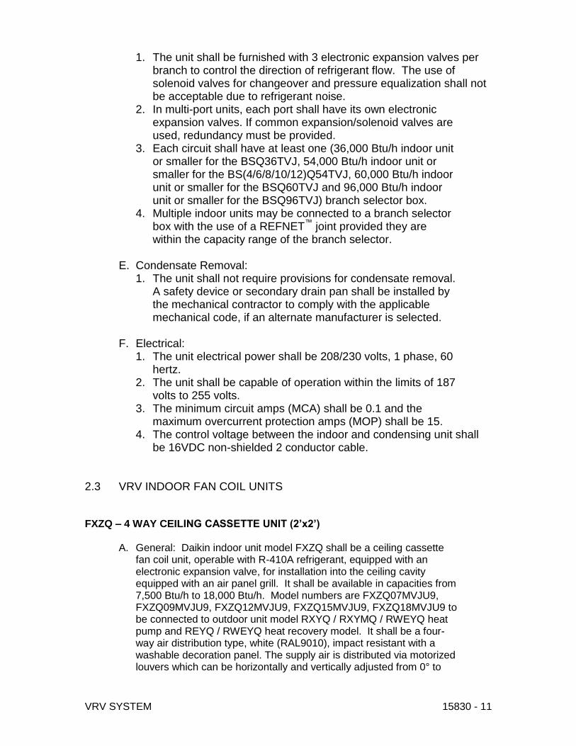
VRV SYSTEM 15830 - 11
1. The unit shall be furnished with 3 electronic expansion valves per branch to control the direction of refrigerant flow. The use of solenoid valves for changeover and pressure equalization shall not be acceptable due to refrigerant noise.
2. In multi-port units, each port shall have its own electronic expansion valves. If common expansion/solenoid valves are used, redundancy must be provided.
3. Each circuit shall have at least one (36,000 Btu/h indoor unit or smaller for the BSQ36TVJ, 54,000 Btu/h indoor unit or smaller for the BS(4/6/8/10/12)Q54TVJ, 60,000 Btu/h indoor unit or smaller for the BSQ60TVJ and 96,000 Btu/h indoor unit or smaller for the BSQ96TVJ) branch selector box.
4. Multiple indoor units may be connected to a branch selector box with the use of a REFNET™ joint provided they are within the capacity range of the branch selector.
E. Condensate Removal:
1. The unit shall not require provisions for condensate removal. A safety device or secondary drain pan shall be installed by the mechanical contractor to comply with the applicable mechanical code, if an alternate manufacturer is selected.
F. Electrical:
1. The unit electrical power shall be 208/230 volts, 1 phase, 60 hertz.
2. The unit shall be capable of operation within the limits of 187 volts to 255 volts.
3. The minimum circuit amps (MCA) shall be 0.1 and the maximum overcurrent protection amps (MOP) shall be 15.
4. The control voltage between the indoor and condensing unit shall be 16VDC non-shielded 2 conductor cable.
2.3 VRV INDOOR FAN COIL UNITS FXZQ – 4 WAY CEILING CASSETTE UNIT (2’x2’)
A. General: Daikin indoor unit model FXZQ shall be a ceiling cassette fan coil unit, operable with R-410A refrigerant, equipped with an electronic expansion valve, for installation into the ceiling cavity equipped with an air panel grill. It shall be available in capacities from 7,500 Btu/h to 18,000 Btu/h. Model numbers are FXZQ07MVJU9, FXZQ09MVJU9, FXZQ12MVJU9, FXZQ15MVJU9, FXZQ18MVJU9 to be connected to outdoor unit model RXYQ / RXYMQ / RWEYQ heat pump and REYQ / RWEYQ heat recovery model. It shall be a four-way air distribution type, white (RAL9010), impact resistant with a washable decoration panel. The supply air is distributed via motorized louvers which can be horizontally and vertically adjusted from 0° to

VRV SYSTEM 15830 - 12
90°. Computerized PID control shall be used to control superheat to deliver a comfortable room temperature condition. The unit shall be equipped with a programmed drying mechanism that dehumidifies while limiting changes in room temperature when used with Daikin remote control BRC1E72, BRC1E73 and BRC2A71. The indoor units sound pressure shall range from 29 dB(A) to 34 dB(A) at low speed measured at 5 feet below the unit.
B. Performance: Each unit’s performance is based on nominal operating conditions
C. Indoor Unit: 1. The Daikin indoor unit FXZQ shall be completely factory
assembled and tested. Included in the unit is factory wiring, piping, electronic proportional expansion valve, control circuit board, fan motor thermal protector, flare connections, condensate drain pan, condensate drain pump, condensate safety shutoff and alarm, self-diagnostics, auto-restart function, 3-minute fused time delay, and test run switch.
2. Indoor unit and refrigerant pipes will be charged with dehydrated air prior to shipment from the factory.
3. Both refrigerant lines shall be insulated from the outdoor unit. 4. The 4-way supply air flow can be field modified to 3-way and 2-
way airflow to accommodate various installation configurations including corner installations.
5. Return air shall be through the concentric panel, which includes a resin net mold resistant filter.
6. The indoor units shall be equipped with a condensate pan and condensate pump. The condensate pump provides up to 21” of lift and has a built in safety shutoff and alarm.
7. The indoor units shall be equipped with a return air thermistor. 8. All electrical components are reached through the decoration
panel, which reduces the required side service access. 9. The indoor unit will be separately powered with 208~230V/1-
phase/60Hz. 10. The voltage range will be 253 volts maximum and 187 volts
minimum. D. Unit Cabinet:
1. The cabinet shall be space saving and shall be located into the ceiling.
2. Three auto-swing positions shall be available to choose, which include standard, draft prevention and ceiling stain prevention.
Model Number Cooling (Indoor 80°F DB / 67°F WB,
Outdoor 95°F DB, 25 ft pipe length)
Heating (Indoor 47°F DB / 43°F WB,
Outdoor 70°F DB, 25 ft pipe length)
FXZQ07MVJU9 7,500 8,700
FXZQ09MVJU9 9,500 11,100
FXZQ12MVJU9 12,000 14,000
FXZQ15MVJU9 15000 17,500
FXZQ18MVJU9 18,000 21,000

VRV SYSTEM 15830 - 13
3. The airflow of the unit shall have the ability to shut down one or two sides allowing for simpler corner installation.
4. Fresh air intake shall be possible by way of direct duct installation to the side of the indoor unit cabinet.
5. The cabinet shall be constructed with sound absorbing foamed polystyrene and polyethylene insulation.
E. Fan: 1. The fan shall be direct-drive turbo fan type with statically and
dynamically balanced impeller with high and low fan speeds available.
2. The fan motor shall operate on 208/230 volts, 1 phase, 60 hertz with a motor output range from 0.06 to 0.12 HP.
3. The airflow rate shall be available in high and low settings. 4. The fan motor shall be thermally protected.
F. Filter: 1. The return air shall be filtered by means of a washable long-life
filter with mildew proof resin. G. Coil:
1. Coils shall be of the direct expansion type constructed from copper tubes expanded into aluminum fins to form a mechanical bond.
2. The coil shall be of a waffle louver fin and high heat exchange, rifled bore tube design to ensure highly efficient performance.
3. The coil shall be a 2-row cross fin copper evaporator coil with 17 FPI design completely factory tested.
4. The refrigerant connections shall be flare connections and the condensate will be 1 -1/32 inch outside diameter PVC.
5. A condensate pan shall be located under the coil. 6. A condensate pump with a 21 inch lift shall be located below the
coil in the condensate pan with a built in safety alarm. 7. A thermistor will be located on the liquid and gas line.
H. Electrical: 1. A separate power supply will be required of 208/230 volts, 1
phase, 60 hertz. The acceptable voltage range shall be 187 to 253 volts.
2. Transmission (control) wiring between the indoor and outdoor unit shall be a maximum of 3,280 feet (total 6,560 feet).
3. Transmission (control) wiring between the indoor unit and remote controller shall be a maximum distance of 1,640 feet.
I. Control: 1. The unit shall have controls provided by Daikin to perform input
functions necessary to operate the system. 2. The unit shall be compatible with interfacing with a BMS system
via optional LonWorks or BACnet gateways. 3. The unit shall be compatible with a Daikin Intelligent Touch
Manager advanced multi-zone controller. J. Optional Accessories Available:
1. Direct fresh air intake kit (KDDQ44X60). 2. Supply air duct connections. 3. Remote “in-room” sensor kit (KRCS01-1B).
i. The Daikin wall mounted, hard wired remote sensor kit is recommended for ceiling-embedded type fan coils, which often

VRV SYSTEM 15830 - 14
result in a difference between set temperature and actual temperature. The sensor for detecting the temperature can be placed away from the indoor unit (branch wiring is included in the kit).
FXMQ_P - CONCEALED CEILING DUCTED UNIT (Med. Static)
A. General: Daikin indoor unit FXMQ_P shall be a built-in ceiling concealed fan coil unit, operable with refrigerant R-410A, equipped with an electronic expansion valve, direct-drive DC (ECM) type fan with auto CFM adjustment at commissioning, for installation into the ceiling cavity. It is constructed of a galvanized steel casing. It shall be available in capacities from 7,500 Btu/h to 48,000 Btu/h. Model numbers are FXMQ07PVJU, FXMQ09PVJU, FXMQ12PVJU, FXMQ18PVJU, FXMQ24PVJU, FXMQ30PVJU, FXMQ36PVJU and FXMQ48PVJU to be connected to outdoor unit model RXYQ / RXYMQ / RWEYQ heat pump and REYQ / RWEYQ heat recovery model. It shall be a horizontal discharge air with horizontal return air configuration. All models feature a low height cabinet making them applicable to ceiling pockets that tend to be shallow. Computerized PID control shall be used to control superheat to deliver a comfortable room temperature condition. The unit shall be equipped with a programmed drying mechanism that dehumidifies while limiting changes in room temperature when used with Daikin remote control BRC1E72 and BRC2A71. Included as standard equipment, a condensate drain pan and drain pump kit that pumps to 18-3/8” from the drain pipe opening. The indoor units sound pressure shall range from 29 dB(A) to 40 dB(A) at low speed measured 5 feet below the ducted unit.
B. Indoor Unit: 1. The Daikin indoor unit FXMQ_P shall be completely factory
assembled and tested. Included in the unit is factory wiring, piping, electronic proportional expansion valve, control circuit board, fan motor thermal protector, flare connections, condensate drain pan, condensate drain pump, condensate safety shutoff and alarm, self-diagnostics, auto-restart function, 3-minute fused time delay, and test run switch. The unit shall be equipment with automatically adjusting external static pressure logic that is selectable during commissioning. This adjusts the airflow based on the installed external static pressure.
2. Indoor unit and refrigerant pipes will be charged with dehydrated air prior to shipment from the factory.

VRV SYSTEM 15830 - 15
3. Both refrigerant lines shall be insulated from the outdoor unit.
4. The indoor units shall be equipped with a condensate pan and condensate pump. The condensate pump provides up to 18-3/8” of lift from the center of the drain outlet and has a built in safety shutoff and alarm.
5. The indoor units shall be equipped with a return air thermistor.
6. The indoor unit will be separately powered with 208~230V/1-phase/60Hz.
7. The voltage range will be 253 volts maximum and 187 volts minimum.
D. Unit Cabinet: 1. The cabinet shall be located into the ceiling and ducted to
the supply and return openings. 2. The cabinet shall be constructed with sound absorbing
foamed polystyrene and polyethylene insulation. E. Fan:
1. The fan shall be direct-drive DC (ECM) type fan, statically and dynamically balanced impeller with three fan speeds available.
2. The unit shall be equipment with automatically adjusting external static pressure logic selectable during commissioning.
3. The fan motor shall operate on 208/230 volts, 1 phase, 60 hertz with a motor output range of 0.12 to 0.47 HP respectively.
4. The airflow rate shall be available in three settings. 5. The fan motor shall be thermally protected. 6. The fan motor shall be equipped as standard with adjustable
external static pressure (ESP) settings. 7. Fan motor external static pressure range for nominal airflow:
F. Coil: 1. Coils shall be of the direct expansion type constructed from
copper tubes expanded into aluminum fins to form a mechanical bond.
2. The coil shall be of a waffle louver fin and high heat exchange, rifled bore tube design to ensure highly efficient performance.
3. The coil shall be a 3 row cross fin copper evaporator coil with 13 fpi design completely factory tested.
4. The refrigerant connections shall be flare connections and the condensate will be 1-1/4” outside diameter PVC.
5. A condensate pan shall be located under the coil. 6. A condensate pump with an 18-3/8” lift shall be located
below the coil in the condensate pan with a built in safety alarm.
7. A thermistor will be located on the liquid and gas line.

VRV SYSTEM 15830 - 16
G. Electrical: 1. A separate power supply will be required of 208/230 volts, 1
phase, 60 hertz. The acceptable voltage range shall be 187 to 253 volts.
2. Transmission (control) wiring between the indoor and outdoor unit shall be a maximum of 3,280 feet (total 6,560 feet).
3. Transmission (control) wiring between the indoor unit and remote controller shall be a maximum distance of 1,640 feet.
H. Control: 1. The unit shall have controls provided by Daikin to perform
input functions necessary to operate the system. 2. The unit shall be compatible with a Daikin intelligent Touch
advanced multi-zone controller or an ITE Itouch customizable BMS.
2.4 CONTROLS, CONTROLS INTEGRATION, GRAPHICS PACKAGE
VARIABLE REFRIGERANT VOLUME (VRV) HVAC SYSTEM
Advanced Multi-zone Controller Part 1 - General 1.01. Physical characteristics
A. General: The advanced multi-zone controller shall be made from plastic materials with a neutral color. Each control shall have a LCD (Liquid Crystal Display) that shows On/Off, setpoint, room temperature, mode of operation (Cool/Heat/Dry/Fan/Auto), louver position, and fan speed. 1.02. Electrical characteristics A. General: The advanced multi-zone controller will require 24 VAC to power the controller. The advanced multi-zone controller shall supply 16 VDC to the communication bus on the F1F2 (out-out) terminal of the outdoor unit. The voltage may rise or fall in relation to the transmission packets that are sent and received. B. Wiring: The advanced multi-zone controller communication wiring shall be terminated in a daisy chain design at the outdoor unit, which is then daisy chained to branch selector (Heat Recovery system), then daisy chained to each indoor unit in the system and terminating at the farthest indoor unit. The termination of the wiring

VRV SYSTEM 15830 - 17
shall be non-polar. The remote control wiring shall run from the indoor unit control terminal block to the remote controller connected with that indoor unit. C. Wiring size: Wiring shall be non-shielded, 2-conductor sheathed vinyl cord or cable, and 18 AWG stranded copper wire. 1.03. VRV Controls Network The VRV Controls Network is made up of local remote controllers, multi-zone controllers, advanced multi-zone controllers, and open protocol network devices that transmit information via the communication bus. The VRV Controls Network shall also have the ability to be accessed via a networked PC. The VRV Controls Network supports operation monitoring, scheduling, error e-mail distribution, general user software, tenant billing, maintenance support, and integration with Building Management Systems (BMS) using open protocol via BACnet® interface , Lonworks® interface or Modbus® adapter; all of which blend to provide the optimal control strategy for the best HVAC comfort solution. Part 2 - Products 2.01. Advanced Multi-zone Controllers The Daikin AC VRV advanced multi-zone controllers are compatible with all VRV, SkyAir, and Daikin RA and FTXS indoor units with the use of the KRP928BB2S RA Adapter. The advanced multi-zone controller wiring consist of a non-polar two-wire connection to the outdoor unit. The advanced multi-zone controllers may be wall-mounted and can be adjusted to maintain the optimal operation of up to 64 connected indoor unit groups and 128 indoor units. Set temperatures can be adjusted in increments of 1°F. In the cases where a system or unit error may occur, the VRV controllers will display a two-digit error code and the unit address.
A. DCM601A71: intelligent Touch Manager (iTM) V2.XX.XX The intelligent Touch Manager (version 2.04) shall provide control for all VRV, SkyAir, and Daikin RA and FTXS indoor units with the use of the KRP928BB2S RA Adapter. It shall be capable of controlling a maximum or 64 indoor unit groups and 128 indoor units connected to a maximum of 10 outdoor units. The intelligent Touch Manager shall support operations superseding that of the local remote controller, system configuration, daily/weekly scheduling, monitoring of operation status, and malfunction monitoring. The controller wiring shall consist of a non-polar two-wire connection to the indoor unit at terminals F1F2 (out-out) of the outdoor unit. The intelligent Touch Manager is wall mounted and can be adjusted to maintain the optimal operation of the connected indoor unit(s). The intelligent Touch Manager can be used in conjunction with the BRC1E73 (Navigation Remote Controller), the BRC2A71 (Simplified Remote Controller), or the BRC4C82/7E83/7C812/7E818 (Wireless Remote Controller), BACnet

VRV SYSTEM 15830 - 18
interface, Lonworks interface, and Modbus adapter to control the same indoor unit groups. The remote controller shall require daisy chain wiring for grouping multiple indoor units (up to 16) together. Manual addressing is required of each remote controller group associated with the intelligent Touch Manager. DIII-NET address can be set for one (1) indoor unit or each indoor unit in the remote controller group. No more than 2 remote controllers can be placed in the same group. The intelligent Touch Manager shall be equipped with two RJ-45 Ethernet ports for 100 Mbps network communication to support interconnection with a network PC via the Internet, Local Area Network (LAN), or connection with a non-networked PC after completed installation. Web access functions shall be available so that facility staff can securely log into each Intelligent Touch Manager via the PC’s web browser to support monitoring, scheduling, error recognition, and general user functions. Error emails are also sent to designated email addresses. An additional optional software function Power Proportional Distribution (PPD) tenant billing shall also be available. The optional software shall require advanced purchase and can only be activated upon receipt of a license activation key from Daikin AC. 1. Mounting: The intelligent Touch Manager shall be mounted on the wall or into the mounting fixtures included with the intelligent Touch Manager. 2. Display Features:
a. The intelligent Touch Manager shall be approximately 11.42” x 9.57” x 1.97’ in size with a backlit 10.4” LCD display.
b. Display information shall be selectable from English, French, Italian, Korean, Dutch, Portuguese, Chinese, Japanese, German, or Spanish.
c. Featured backlit LCD with auto off after 30 minutes (default) is adjustable between 1 to 60 minutes, or the choice of 3 different screen savers.
d. Area and Group configuration 1) Area contains one (1) or more Area(s) or Group(s) 2) A Group may be an indoor unit, Di, Dio point that has a DIII-Net
address 3) A Group may be an external management point such as a Di,
Do, Bi, Bo, Bv, Ai, Ao, Av, Mi, Mo, Mv that does not have a DIII-Net address
e. An Area is a tiered group where management points (indoor unit, digital input/output, and analog input/output groups) can be monitored and controlled by global settings. Up to 650 Areas can be created. Area hierarchy can have up to 10 tiered levels (ex. top level: 1st floor West, 2nd level: offices, hallways, 3rd level: Office 101, 102, and 103, etc.). Area configuration shall classify levels of monitoring and control for each management point

VRV SYSTEM 15830 - 19
1) Areas and Groups may be assigned names (ex. Office 101, Lobby, North Hallway, etc.)
f. The Controller shall display On/Off, Operation Mode, Setpoint, Space Temperature, Louver Position, Fan Speed for each Area or Group.
g. The Controller shall display Date (mm/dd/yyyy, yyyy/mm/dd, or dd/mm/yyyy format selectable) and day of the week along with the time of day (12hr or 24hr display selectable).
h. The Controller shall adjust for daylight savings time (DST) automatically.
i. Display information shall be updated every 3 seconds to show the latest status of the indoor unit groups.
j. System status icons shall display On/Off (color coded), Malfunction/Error (color coded), Forced Stop, Setback, Filter, Maintenance, and Screen Lock.
k. The controller shall display the temperature setpoint in one degree increments with a range of 60oF – 90oF, 1oF basis (16oC – 32oC, 0.1oC basis). 1) Display of temperature setpoint information shall be configurable
for Fahrenheit or Celsius l. Display shall reflect room temperature in one tenth degree
increments with a range of-58oF – 248oF, 0.1oF basis (-50oC – 120oC, 0.1oC basis) with 0.1oC accuracy. 1) Display of room temperature information shall be configurable for
Fahrenheit or Celsius m. The Menu List shall be used to configure options and display
information for each Area or Group. n. Error status shall be displayed in the event of system
abnormality/error with one of three color coded icons placed over the indoor unit icon or lower task bar. 1) System errors are generated when the intelligent Touch Manager
system with other VRV controls systems are combined incorrectly or power proportional distribution calculation errors occur. The intelligent Touch Manager shall display the error with a red triangle placed on the lower task bar.
2) Unit errors occurring within the VRV system shall be displayed with a yellow triangle placed over the indoor unit icon
3) Limit errors are based upon preconfigured analog input upper and lower limit settings and are generated when the limits have been met. When limit error is generated a yellow triangle will be placed over the unit icon.
4) Communication errors between the intelligent Touch Manager and the indoor units shall be displayed with a blue triangle placed over the indoor unit icon
5) Error history shall be available for viewing for up to 500,000 errors/abnormality events with operation events.
o. Layout View 1) Capable of displaying site floor plan or graphical user interface
(GUI) as the background for visual navigation. Indoor unit, DIII-
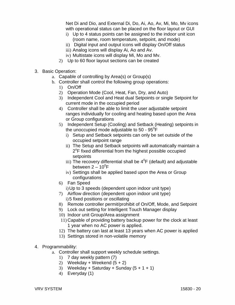
VRV SYSTEM 15830 - 20
Net Di and Dio, and External Di, Do, Ai, Ao, Av, Mi, Mo, Mv icons with operational status can be placed on the floor layout or GUI i) Up to 4 status points can be assigned to the indoor unit icon
(room name, room temperature, setpoint, and mode) ii) Digital input and output icons will display On/Off status iii) Analog icons will display Ai, Ao and Av. iv) Multistate icons will display Mi, Mo and Mv.
2) Up to 60 floor layout sections can be created 3. Basic Operation:
a. Capable of controlling by Area(s) or Group(s) b. Controller shall control the following group operations:
1) On/Off 2) Operation Mode (Cool, Heat, Fan, Dry, and Auto) 3) Independent Cool and Heat dual Setpoints or single Setpoint for
current mode in the occupied period 4) Controller shall be able to limit the user adjustable setpoint
ranges individually for cooling and heating based upon the Area or Group configurations
5) Independent Setup (Cooling) and Setback (Heating) setpoints in the unoccupied mode adjustable to 50 - 950F i) Setup and Setback setpoints can only be set outside of the
occupied setpoint range ii) The Setup and Setback setpoints will automatically maintain a
2oF fixed differential from the highest possible occupied setpoints
iii) The recovery differential shall be 40F (default) and adjustable between 2 – 100F
iv) Settings shall be applied based upon the Area or Group configurations
6) Fan Speed i) Up to 3 speeds (dependent upon indoor unit type)
7) Airflow direction (dependent upon indoor unit type) i) 5 fixed positions or oscillating
8) Remote controller permit/prohibit of On/Off, Mode, and Setpoint 9) Lock out setting for Intelligent Touch Manager display 10) Indoor unit Group/Area assignment 11) Capable of providing battery backup power for the clock at least
1 year when no AC power is applied. 12) The battery can last at least 13 years when AC power is applied 13) Settings stored in non-volatile memory
4. Programmability:
a. Controller shall support weekly schedule settings. 1) 7 day weekly pattern (7) 2) Weekday + Weekend (5 + 2) 3) Weekday + Saturday + Sunday (5 + 1 + 1) 4) Everyday (1)

VRV SYSTEM 15830 - 21
5) The schedule shall have the capabilities of being enabled or disabled
6) 100 independent schedules configurable with up to 20 events settable for each days schedule i) Each scheduled event shall specify time and target Area or
Group ii) Each scheduled event shall include On/Off, Optimum Start,
Operation Mode, Occupied Setpoints, Setback Setpoints, Remote Controller On/Off Prohibit, Remote Controller Mode Prohibit, Remote Controller Setpoint Prohibit, Timer Extension Setting, Fan Speed, and Setpoint Range Limit
Setpoint when unit is On (occupied)
Configurable Setup (Cooling) and Setback (Heating) setpoints when unit is Off (unoccupied)
iii) Time setting in 1-minute increments iv) Timer Extension shall be used for a
timed override (settable from 30 – 180 minutes) to allow indoor unit operation during the unoccupied period
7) A maximum of 40 exception days can be schedule on the yearly schedule (repeats yearly) i) Exception days shall be used to
override specified days on the weekly schedule based upon irregular occupied/unoccupied conditions
ii) Exception days can be configured on a set date (Jan 1) or floating date (1st Monday in September)
b. Controller shall support auto-changeover. 1) Auto-change shall provide Fixed (default), Individual, Averaging,
and Vote changeover methods for both Heat Pump and Heat Recovery systems based upon the changeover group configuration. This will allow for the optimal room temperature to be maintained by automatically switching the indoor unit’s mode between Cool and Heat in accordance with the room temperature and setpoint. The following changeover scheme shall be applicable to the Fixed, Individual, and Averaging methods. i) Changeover to cooling mode shall occur at cooling setpoint +
1oF (0.5oC) as the primary changeover deadband and takes the guard timer into consideration
Configurable from 1 – 4oF (0.5 – 2oC) ii) Changeover to cooling mode shall occur at the primary
changeover deadband to cooling + 1oF (0.5oC) as the secondary changeover deadband.
Configurable from 1 – 4oF (0.5 – 2oC) iii) Changeover to heating mode shall occur at heating setpoint -
1oF (0.5oC) as the primary changeover deadband and takes the guard timer into consideration
Configurable from 1 – 4oF (0.5 – 2oC)

VRV SYSTEM 15830 - 22
iv) Changeover to heating mode shall occur at the primary changeover deadband to heating - 1oF (0.5oC) as the secondary changeover deadband.
Configurable from 1 – 4oF (0.5 – 2oC) v) A weighted demand shall be configurable for the Averaging
and Vote methods. 2) Fixed Method
i) Changeover evaluated by room temperature and setpoint of the representative indoor unit (first registered indoor unit in changeover group) in the changeover group even when it is not operating (must be in Cool, Heat, or Auto mode)
ii) Changeover affects all indoor unit groups in the changeover group.
3) Individual method (recommended for Heat Recovery Systems) i) Changeover evaluated by room
temperature and setpoints of the individual indoor unit group in the changeover group
ii) Changeover affects individual indoor unit group in the changeover group
4) Average method i) Changeover evaluated by the
average of all indoor unit group’s room temperatures and setpoints operating in Cool, Heat, or Auto mode in the changeover group list
ii) If none of the indoor units in the group meet the above requirements the Fixed method of changeover will be applied
iii) A weighted demand (0 – 3) can be configured for each indoor unit in the changeover group.
iv) Changeover affects all indoor unit groups in the changeover group.
5) Vote Method i) In each indoor unit, the cooling demand is calculated based
upon the difference between the room temperature and cooling setpoint. If the room temperature falls below the primary cool changeover point (cool setpoint plus the primary changeover deadband) the cooling demand is considered as 0 (zero). Then the total cooling demand is calculated as the sum of each indoor unit’s cooling demand
ii) The opposite is true for the total heating demand iii) A weight (0-3) can be added to each indoor unit’s demand in
the changeover group. The default setting is 1 iv) The weight 0 (zero) means the indoor unit’s demand is not
added in the total demand, so the indoor unit’s demand is considered to be 0 (zero)
v) The weight 2 or 3 means the indoor unit’s demand is added 2 or 3 times in the total demand, respectively

VRV SYSTEM 15830 - 23
vi) Changeover to cooling mode shall occur when the total cooling demand is greater than the total heating demand.
vii) The opposite is true for changeover to heating viii) Vote supports a Heating Override option, which prioritizes
switching to the heating mode if at least one room temperature falls below the secondary heat changeover point (heat setpoint minus the secondary changeover deadband) even if the total cooling demand is greater than the total heating demand.
ix) Changeover affects all indoor unit groups in the changeover group.
6) Changeover shall change the operation mode of the indoor unit
that is set as the Changeover Master. The Changeover Master indoor unit shall then change the operation mode of all indoor unit groups daisy chained to the same outdoor unit in the Heat Pump system or branch selector box in the Heat Recovery system.
7) Guard timer i) Upon changeover, guard timer will
prevent another changeover during the guard timer activation period (15, 30, 60 (default) min).
ii) Guard timer is ignored by a change of setpoint manually from either intelligent Touch Manger or Remote Controller, by schedule, or the room temperature meets or exceeds the secondary changeover deadband of the mode opposite of the current mode setting
c. Controller shall support Interlock 1) Interlock feature for use with 3rd party equipment (DOAS,
dampers, occupancy sensing, etc…) to automatically control Groups or Areas corresponding to the change of the operation states or the On/Off states of any Group.
2) WAGO I/O unit – Di, Do, Ai, Ao i) On/Off based monitoring and control of equipment ii) Manual or scheduled operation of equipment iii) Operation based upon interlock with management
points (group(s)) iv) Monitor equipment error/alarm status
3) Digital Input/Output (DEC102A51-US2) unit or Digital Input (DEC101A51-US2) unit i) On/Off based monitoring and control of equipment ii) Manual or scheduled operation of equipment iii) Operation based upon interlock with management
points (group(s)) iv) Monitor equipment error/alarm status
d. Controller shall support force shutdown of associated indoor unit groups.
5. Web/Email Function

VRV SYSTEM 15830 - 24
a. Each intelligent Touch Manager shall be capable of monitoring, operating, and scheduling a maximum of 64 indoor unit groups (up to 512 indoor unit groups with the addition of the iTM Plus Adapter) from a networked PC’s web browser. It shall also be capable of creating general user access and sending detailed error emails to a customized distribution list (up to 10 email addresses).
b. All PCs shall be field supplied 6. Optional Software Licensed per option, per intelligent Touch Manager shall be required.
a. DCM002A71: Power Proportional Distribution (PPD) The tenant billing option shall be capable of calculating VRV Controls Network equipment energy usage in kWh based on the energy consumption of the outdoor unit(s) divided among the associated indoor units. This software is used in conjunction with the intelligent Touch Manager and a Watt Hour Meter (WHM). A maximum of 3 Watt Hour Meters can be connected to the intelligent Touch Manager. Up to 4 additional Watt Hour Meters can be connected to each iTM Plus Adapter, and up to 7 iTM Plus Adapters can be connected to the intelligent Touch Manager. The Power Proportional Distribution results data can be saved to a USB flash drive, or on a PC with the use of the web access. Data is saved in the CSV format. Results can be stored up to 13 months in the intelligent Touch Manager.
b. DCM009A51: BACnet Client Option 1) The iTM BACnet Client Option shall be capable of making the
intelligent Touch Manager work as a BACnet client using the BACnet/IP protocol. A BACnet client machine is able to send service requests to a BACnet server machine that then performs the services and reports the results to the client. By registering equipment and sensors connected to a BACnet server as management points, equipment and sensors can be monitored and controlled by the intelligent Touch Manager. The BACnet Client option must be enabled/ activated in each intelligent Touch Manager to be used.
2) System Capacity i) A maximum of 50 BACnet servers can be monitored
and/or controlled by one intelligent Touch Manager. ii) A maximum of 1536 objects can be monitored and/or
controlled by one intelligent Touch Manager. iii) A maximum of 512 management points, including
BACnet management points, external management points, internal Ai management points, AHU management points, and Chiller management points, can be registered in one intelligent Touch Manager.
3) Objects that can be used in BACnet management points are: i) Analog Input (Object Type Number 0) ii) Analog Output (Object Type Number 1) iii) Analog Value (Object Type Number 2)

VRV SYSTEM 15830 - 25
iv) Binary Input (Object Type Number 3) v) Binary Output (Object Type Number 4) vi) Binary Value (Object Type Number 5) vii) Multi-Sate Input (Object Type Number 13) viii) Multi-Sate Output (Object Type Number 14) ix) Multi-Sate Value (Object Type Number 19)
c. DCM014A51: BACnet Server Gateway Option
1) The iTM BACnet Server Gateway Option shall be capable of making the intelligent Touch Manager work as a BACnet gateway using the BACnet/IP protocol. The iTM BACnet Server Gateway Option shall be capable of exposing indoor unit
management points as BACnet objects to the (BMS). The iTM
BACnet Server/Gateway Option shall be capable of allowing the BMS to monitor and control indoor units BACnet objects.
2) The iTM BACnet Server Gateway Option shall be compatible with VRV, SkyAir, Outdoor Air Processing Unit, Mini-Split system with use of KRP928, and FFQ indoor unit for Multi-split system.
3) Functions: i. The iTM BACnet Server Gateway Option shall be
capable of supporting Change of Value (COV) notification.
ii. The iTM BACnet Server Gateway Option shall communicate to BMS using port number 47808 (configurable).
iii. The iTM BACnet Server Gateway Option shall function as BACnet router to provide unique virtual BACnet device identification number (ID) for every indoor unit group address.
iv. The iTM BACnet Server Gateway Option shall provide configurable BACnet Network number.
v. The iTM BACnet Server Gateway Option shall be capable of being configured as a foreign device. It shall be capable of communicating across BACnet Broadcast Management Devices (BBMD) in different subnet networks.
vi. The iTM BACnet Server Gateway Option shall be run in environments with BACnet communication traffic up to 100 packets/second.
vii. The iTM BACnet Server Gateway Option functions shall be configurable through CSV file which shall be downloaded from iTM and configured by trained personnel.
4) System Capacity i. Max of 128 indoor units groups (Up to 256 indoor units)
can be controlled from (BMS) ii. Max of 8 DIII-Net ports shall be connected to iTM.

VRV SYSTEM 15830 - 26
5) The Building Management System shall monitor and control the following BACnet objects for indoor units
i. Indoor unit ON/OFF status. ii. Alarm status with error description iii. Room temperature. iv. Indoor Unit ON details
Off
Normal [ON]
Override
Setback v. Filter sign status. vi. Fan status. vii. Communication status. viii. Thermo-on status. ix. Compressor status
On
Off
Defrost x. Aux heater status. xi. Occupancy Mode
Unoccupied,
Occupied
Standby xii. Operation Mode (Cool, Heat, Fan, and Dry) xiii. Cooling and Heating setpoints during occupied mode. xiv. Cooling and Heating setpoints during unoccupied mode. xv. Maximum and minimum cooling setpoint. xvi. Maximum and Minimum heating setpoint xvii. Minimum cooling and heating setpoint differential. xviii. Fan Speed
Up to 3 speeds (dependent upon indoor unit type) xix. Vane direction (dependent upon indoor unit type)
5 fixed positions or swing position xx. Remote controller permit/prohibit
On/Off
Mode,
Setpoint xxi. Filter sign reset for indoor units xxii. Forced indoor units off.
6) The Building Management System may choose to monitor and control the following BACnet objects linked to iTM control logic:
i. Enable/Disable iTM Schedule operation. ii. Enable/Disable iTM Auto Changeover Operation. iii. Set Timed Override Minutes.
Monitor and configure timer extension on iTM (30, 60, 90, 120, 150, 180 minutes)
iv. System forced off

VRV SYSTEM 15830 - 27
Enable/Disable all emergency stop programs that are registered on the iTM.
7) Schedule The BMS shall utilize iTM schedule function or support weekly schedule settings through its programming.
i. BMS schedule shall support the indoor unit:
Each scheduled event shall specify time and target group address.
Each scheduled event shall include Occupancy Mode, Operation Mode, Occupied Cooling Setpoint, Occupied Heating Setpoint, and Unoccupied cooling setpoint, Unoccupied heating setpoint, Remote Controller On/Off Permit/Prohibit, Remote Controller Mode Permit/Prohibit, Remote Controller Setpoint Permit/Prohibit, and Timed Override Enable.
An override shall be provided for use enabling indoor unit operation during the unoccupied period by the BMS programming.
8) Auto Changeover The BMS shall utilize iTM Auto changeover function or support auto-changeover through its programming.
i. Auto-change shall provide changeover for both Heat Pump and Heat Recovery systems based upon the group configurations. This will allow the optimal room temperature to be maintained by automatically switching the indoor unit’s mode between Cool and Heat in accordance with the room temperature and setpoint temperature.
ii. Changeover shall change the operation mode of the indoor unit that is set as the Changeover Master. The Changeover Master indoor unit shall then change the operation mode of all indoor unit groups daisy chained on the same DIII-Net communication bus to the same outdoor unit in the Heat Pump system or the same branch selector box in the Heat Recovery system.
iii. Changeover to cooling mode shall occur when the room temperature is great than or equal to the cooling setpoint
Differential to be determined by BACnet building management system programming
iv. Changeover to heating mode shall occur when room temperature is less than or equal to the heating setpoint.
Differential to be determined by BACnet building management system programming
v. Guard timer
Upon changeover, guard timer will prevent another changeover during this period.

VRV SYSTEM 15830 - 28
Guard timer should be ignored by a change of setpoint manually from the BMS, Intelligent Touch Controller, Remote Controller, or by schedule.
Guard timer to be configured by BMS programming (30 minute minimum recommended)
9) Setpoint limitation
The BMS shall utilize maximum and minimum cooling and heating setpoint to configure upper and lower setpoints range.
10) System shutdown: BMS should utilize System forced off point to execute emergency stop program registered on the iTM.
11) Restricted functions: The following iTM functions shall be prohibited when the BACnet Server Gateway option enabled:
i. Interlocking Control. ii. Emergency Stop (Emergency stop manual release). iii. Power Proportional Distribution (PPD) option. iv. BACnet Client option. v. D-Net Service. vi. External Management Point Registration
B. DCM601A72: iTM Plus Adapter
The iTM Plus Adapter shall provide control for all VRV, SkyAir indoor units, and Daikin RA and FTXS indoor units with the use of the KRP928BB2S RA Adapter. It shall be capable of handling a maximum of 64 indoor unit groups and 128 indoor units connected to a maximum of 10 outdoor units. The iTM Plus Adapter is to be used in conjunction with intelligent Touch Manager. Up to 7 iTM Plus Adapters can be connected to a single intelligent Touch Manager. This combination will provide intelligent Touch Manager monitoring and control of up to 512 indoor unit groups, 1024 indoor units, and 80 outdoor units. The iTM Plus Adapter shall support operations superseding that of the local remote controller, system configuration, daily/weekly scheduling, monitoring of operation status, and malfunction monitoring. The controller wiring shall consist of a non-polar two-wire connection to the outdoor unit at terminals F1F2 (out-out). The iTM Plus Adapter is wall mounted and is used in conjunction with the intelligent Touch Manager to maintain the optimal operation of the connected indoor unit(s). The iTM Plus Adapter is connected to the intelligent Touch Manager via a polarity sensitive 18-2 AWG stranded non-shielded wire (field supplied). The iTM Plus Adapter can be used in conjunction with the BRC1E73 (Navigation Remote Controller), the BRC2A71 (Simplified Remote Controller), or the BRC4C82/7E83/7C812/7E818 (Wireless Remote Controller), BACnet interface, Lonworks interface and Modbus Adapter to control the same indoor unit groups. No more than 2 remote controllers can be placed in the same group. The remote controller shall require daisy chain wiring for grouping multiple indoor units (up to

VRV SYSTEM 15830 - 29
16) together. Manual addressing is required of each indoor unit group associated with the iTM Plus Adapter. 1. Mounting: The iTM Plus Adapter can be mounted on the wall or in a standard enclosure (field supplied). 2. Features:
a. The iTM Plus Adapter shall be approximately 6.30” x 5.87” x 2.41” in size.
3. Basic Operation:
a. Control of all associated indoor unit groups shall be done via the connected intelligent Touch Manager.
4. Programmability:
a. Programming of all associated indoor unit groups shall be done via the connected intelligent Touch Manager.
PART 3 – EXECUTION 3.1 INSTALLATION
A. Connect refrigerant piping to outdoor VRV units. B. Electrical: Refer to “Basic Electircal Requirements” for electrical
connections to mechanical equipment.
3.2 FIELD QUALITY CONTROL
A. Leak Test: After installation, charge systems with refrigerant and oil and test for leaks. Repair leaks and replace lost refrigerant and oil.
B. Operational Test: After electrical circuitry has been energized, start
units to confirm proper operation, product capability, and compliance with requirements.
1. Test and adjust controls and safeties. Replace damaged and malfunctioning controls and equipment.
B. Remove and replace malfunctioning units with new units and retest.
END OF SECTION 238200

POWER VENTILATORS 15853 - 1
SECTION 15853 - POWER VENTILATORS
1.1 GENERAL
A. Submittals: Submit Product Data for each item in this Article according to the Conditions of
the Contract and Division 1 Specification Sections.
B. Electrical Component Standard: Provide components that comply with NFPA 70 and that are
listed and labeled by UL where available.
C. Listing and Labeling: Provide electrically operated fixtures specified in this Section that are
UL listed and labeled.
D. AMCA Compliance: Provide products that meet performance requirements and are licensed to
use the AMCA Seal.
E. NEMA Compliance: Provide components required as part of fans that comply with applicable
NEMA standards.
F. UL Standard: Provide power ventilators that comply with UL 705.
1.2 PRODUCTS
A. Ceiling-Mounted Ventilators: Centrifugal fans designed for installing in ceiling or wall, or for
concealed in-line applications.
1. Housing: Galvanized steel lined with acoustical insulation.
2. Fan Wheel: Centrifugal wheels directly mounted on motor shaft. Fan shrouds, motor,
and fan wheel shall be removable for service.
3. Grille: Louvered grille with flange on intake and thumbscrew attachment to fan housing.
4. Electrical Requirements: Junction box for electrical connection on housing and
receptacle for motor plug-in.
5. Accessories: Manufacturer's standard roof jack or wall cap, and transition fittings.
E. In-Line Centrifugal Fans: In-line, belt-driven centrifugal fans consisting of housing, wheel,
outlet guide vanes, fan shaft, bearings, drive assembly, motor and disconnect switch, mounting
brackets, and accessories.
1. Housing: Split, spun-aluminum housing, with aluminum straightening vanes; inlet and
outlet flanges; and support bracket adaptable to floor, side wall, or ceiling mounting.
2. Belt-Driven Units: Motor mounted on adjustable base, with adjustable sheaves,
enclosure around belts within fan housing, and lubricating tubes from fan bearings
extended to outside of fan housing.
3. Fan Wheels: Aluminum, airfoil blades welded to aluminum hub.
4. Volume-Control Damper: Manually operated with quadrant lock, located in fan outlet.
5. Companion Flanges: For inlet and outlet duct connections.

POWER VENTILATORS 15853 - 2
6. Fan Guards: Expanded metal in removable frame. Provide belt guards for units not
connected to ductwork.
F. Motors: Refer to Division 15 Section "Motors" for general requirements for factory-installed
motors.
1. Motor Construction: NEMA MG 1, general purpose, continuous duty, Design B.
2. Open dripproof motors where satisfactorily housed or remotely located during operation.
3. Guarded dripproof motors where exposed to contact by employees or building occupants.
G. Factory Finishes: Prime coat sheet metal parts before final assembly. Apply baked-enamel
finish coat to exterior surfaces after assembly. Aluminum parts require no finish.
1.3 EXECUTION
A. Install power ventilators according to manufacturer's written instructions.
B. Support units using the vibration-control devices indicated.
C. Suspend units from structural steel support frame using threaded steel rods and vibration
isolation springs.
D. Ceiling Units: Suspend units from structure using steel wire or metal straps.
E. Install units with clearances for service and maintenance.
F. Duct installation and connection requirements are specified in other Division 15 Sections.
Drawings indicate the general arrangement of ducts and duct accessories. Make final duct
connections with flexible connectors.
G. Electrical: Conform to applicable requirements in Division 16 Sections.
H. Grounding: Ground equipment. Tighten electrical connectors and terminals, including
grounding connections, according to manufacturer's published torque-tightening values. Where
manufacturer's torque values are not indicated, use those specified in UL 486A and UL 486B.
END OF SECTION 15853

SECTION 15855 – DIFFUSERS, REGISTERS AND GRILLES 15855 - 1
SECTION 15855 – DIFFUSERS, REGISTERS AND GRILLES
PART 1 - GENERAL
1.1 RELATED DOCUMENTS
A. Drawings and general provisions of the Contract, including General and Supplementary
Conditions and Division 1 Specification Sections, apply to this Section.
1.2 SUMMARY
A. This Section includes ceiling - and wall-mounted diffusers, registers, and grilles.
B. Related Sections include the following:
1. Division 15 Section “Duct Accessories” for fire and smoke dampers and volume-
control dampers not integral to diffusers, registers, and grilles.
3. Division 15 Section “Testing, Adjusting, and Balancing” for balancing diffusers,
registers, and grilles.
1.3 SUBMITTALS
A. Product Data: For each model indicated, include the following:
B. Data Sheet: For each type of air outlet and inlet, and accessory furnished; indicate
construction, finish, and mounting details.
C. Performance Data: Include throw and drop, static-pressure drop, and noise ratings for each
type of air outlet and inlet.
1.4 QUALITY ASSURANCE
A. Product Options: Drawings and schedules indicate specific requirements of diffusers,
registers, and grilles and are based on the specific requirements of the systems indicated.
Other manufacturers’ products with equal performance characteristics may be considered.
PART 2 - PRODUCTS
2.1 MANUFACTURED UNITS
A. Diffusers, registers, and grilles are scheduled at the end of this Section.
B. Diffusers, registers, and grilles are scheduled on Drawings.
PART 3 - EXECUTION
3.1 EXAMINATION
A. Examination areas where diffusers, registers, and grilles are to be installed for compliance
with requirements for installation tolerances and other conditions affecting performance of
equipment. Do not proceed with installation until unsatisfactory conditions have been

SECTION 15855 – DIFFUSERS, REGISTERS AND GRILLES 15855 - 2
corrected.
3.2 INSTALLATION
A. Install diffusers, registers, and grilles level and plumb, according to manufacturer’s written
instructions, Coordination Drawings, original design, and referenced standards.
B. Ceiling-Mounted Outlets and Inlets: Drawings indicate general arrangement of ducts,
fittings, and accessories. Air outlet and inlet locations have been indicated to achieve design
requirements for air volume, noise criteria, airflow pattern, throw, and pressure drop. Make
final locations where indicated, as much as practicable. For units installed in lay-in ceiling
panels, locate units in the center of the panel. Where architectural features or other items
conflict with installation, notify Architect for a determination of final location.
C. Install diffusers, registers, and grilles with airtight connection to ducts and to allow service
and maintenance of dampers, air extractors, and fire dampers.
3.3 ADJUSTING
A. After installation, adjust diffusers, registers, and grilles to air patterns indicated, or as
directed, before starting air balancing.
3.4 CLEANING
A. After installation of diffusers, registers, and grilles, inspect exposed finish. Clean exposed
surfaces to remove burrs, dirt, and smudges. Replace diffusers, registers, and grilles that have
damaged finishes.
END OF SECTION 15855

TESTING, ADJUSTING, AND BALANCING 15990 - 1
SECTION 15990 - TESTING, ADJUSTING, AND BALANCING
PART 1 - GENERAL
1.1 RELATED DOCUMENTS
A. Drawings and general provisions of the Contract, including General and Supplementary
Conditions and Division 1 Specification Sections, apply to this Section.
1.2 SUMMARY
A. This Section includes testing, adjusting, and balancing HVAC systems to produce
design objectives, including the following:
1. Balancing airflow and water flow within distribution systems, including
submains, branches, and terminals, to indicated quantities according to specified
tolerances.
2. Adjusting total HVAC systems to provide indicated quantities.
3. Measuring electrical performance of HVAC equipment.
4. Setting quantitative performance of HVAC equipment.
5. Verifying that automatic control devices are functioning properly.
6. Measuring sound and vibration.
7. Reporting results of the activities and procedures specified in this Section.
B. Related Sections include the following:
1. Testing and adjusting requirements unique to particular systems and equipment
are included in the Sections that specify those systems and equipment.
2. Field quality-control testing to verify that workmanship quality for system and
equipment installation is specified in system and equipment Sections.
1.3 DEFINITIONS
A. Adjust: To regulate fluid flow rate and air patterns at the terminal equipment, such as to
reduce fan speed or adjust a damper.
B. Balance: To proportion flows within the distribution system, including submains,
branches, and terminals, according to design quantities.
C. Draft: A current of air, when referring to localized effect caused by one or more factors
of high air velocity, low ambient temperature, or direction of airflow, whereby more
heat is withdrawn from a person's skin than is normally dissipated.

TESTING, ADJUSTING, AND BALANCING 15990 - 2
D. Procedure: An approach to and execution of a sequence of work operations to yield
repeatable results.
E. Report Forms: Test data sheets for recording test data in logical order.
F. Static Head: The pressure due to the weight of the fluid above the point of
measurement. In a closed system, static head is equal on both sides of the pump.
G. Suction Head: The height of fluid surface above the centerline of the pump on the
suction side.
H. System Effect: A phenomenon that can create undesired or unpredicted conditions that
cause reduced capacities in all or part of a system.
I. System Effect Factors: Allowances used to calculate a reduction of the performance
ratings of a fan when installed under conditions different from those presented when the
fan was performance tested.
J. Terminal: A point where the controlled medium, such as fluid or energy, enters or
leaves the distribution system.
K. Test: A procedure to determine quantitative performance of a system or equipment.
L. Testing, Adjusting, and Balancing Agent: The entity responsible for performing and
reporting the testing, adjusting, and balancing procedures.
M. AABC: Associated Air Balance Council.
N. AMCA: Air Movement and Control Association.
O. CTI: Cooling Tower Institute.
P. NEBB: National Environmental Balancing Bureau.
Q. SMACNA: Sheet Metal and Air Conditioning Contractors' National Association.
1.4 SUBMITTALS
A. Quality-Assurance Submittals: Within 30 days from the Contractor's Notice to Proceed,
submit 2 copies of evidence that the testing, adjusting, and balancing Agent and this
Project's testing, adjusting, and balancing team members meet the qualifications
specified in the "Quality Assurance" Article below.

TESTING, ADJUSTING, AND BALANCING 15990 - 3
B. Certified Testing, Adjusting, and Balancing Reports: Submit 3 copies of reports
prepared, as specified in this Section, on approved forms certified by the testing,
adjusting, and balancing Agent.
1.4 QUALITY ASSURANCE
A. Agent Qualifications: Engage a testing, adjusting, and balancing agent certified by
either AABC or NEBB.
B. Certification of Testing, Adjusting, and Balancing Reports: Certify the testing,
adjusting, and balancing field data reports. This certification includes the following:
1. Review field data reports to validate accuracy of data and to prepare certified
testing, adjusting, and balancing reports.
2. Certify that the testing, adjusting, and balancing team complied with the approved
testing, adjusting, and balancing plan and the procedures specified and referenced
in this Specification.
C. Testing, Adjusting, and Balancing Reports: Use testing, adjusting, and balancing
Agent's standard forms.
D. Instrumentation Type, Quantity, and Accuracy: As described in AABC national
standards. Or as described in NEBB's "Procedural Standards for Testing, Adjusting, and
Balancing of Environmental Systems," Section II, "Required Instrumentation for NEBB
Certification."
E. Instrumentation Calibration: Calibrate instruments at least every 6 months or more
frequently if required by the instrument manufacturer.
1.5 COORDINATION
A. Coordinate the efforts of factory-authorized service representatives for systems and
equipment, HVAC controls installers, and other mechanics to operate HVAC systems
and equipment to support and assist testing, adjusting, and balancing activities.
B. Notice: Provide 7 days' advance notice for each test. Include scheduled test dates and
times.
C. Perform testing, adjusting, and balancing after leakage and pressure tests on air and
water distribution systems have been satisfactorily completed.
1.6 WARRANTY

TESTING, ADJUSTING, AND BALANCING 15990 - 4
A. National Project Performance Guarantee: Provide a guarantee on AABC'S "National
Standards" forms stating that AABC will assist in completing the requirements of the
Contract Documents if the testing, adjusting, and balancing Agent fails to comply with the
Contract Documents. Guarantee includes the following provisions:
1. The certified Agent has tested and balanced systems according to the Contract
Documents.
2. Systems are balanced to optimum performance capabilities within design and
installation limits.
PART 2 - PRODUCTS (Not Applicable)
PART 3 - EXECUTION
3.1 EXAMINATION
A. Examine Contract Documents to become familiar with project requirements and to
discover conditions in systems' designs that may preclude proper testing, adjusting, and
balancing of systems and equipment.
1. Contract Documents are defined in the General and Supplementary Conditions of
the Contract.
2. Verify that balancing devices, such as test ports, gage cocks, thermometer wells,
flow-control devices, balancing valves and fittings, and manual volume dampers,
are required by the Contract Documents. Verify that quantities and locations of
these balancing devices are accessible and appropriate for effective balancing and
for efficient system and equipment operation.
B. Examine approved submittal data of HVAC systems and equipment.
C. Examine Architect's and Engineer's design data, including HVAC system descriptions,
statements of design assumptions for environmental conditions and systems' output, and
statements of philosophies and assumptions about HVAC system and equipment
controls.
D. Examine system and equipment installations to verify that they are complete and that
testing, cleaning, adjusting, and commissioning specified in individual Specification
Sections have been performed.
E. Examine system and equipment test reports.

TESTING, ADJUSTING, AND BALANCING 15990 - 5
F. Examine HVAC system and equipment installations to verify that indicated balancing
devices, such as test ports, gage cocks, thermometer wells, flow-control devices,
balancing valves and fittings, and manual volume dampers, are properly installed, and
their locations are accessible and appropriate for effective balancing and for efficient
system and equipment operation.
G. Examine systems for functional deficiencies that cannot be corrected by adjusting and
balancing.
H. Examine air-handling equipment to ensure clean filters have been installed, bearings are
greased, belts are aligned and tight, and equipment with functioning controls is ready for
operation.
I. Examine plenum ceilings, utilized for supply air, to verify that they are airtight. Verify
that pipe penetrations and other holes are sealed.
J. Examine equipment for installation and for properly operating safety interlocks and
controls.
3.2 PREPARATION
A. Prepare a testing, adjusting, and balancing plan that includes strategies and step-by-step
procedures.
B. Complete system readiness checks and prepare system readiness reports. Verify the
following:
1. Permanent electrical power wiring is complete.
2. Automatic temperature-control systems are operational.
3. Equipment and duct access doors are securely closed.
4. Balance, smoke, and fire dampers are open.
5. Ceilings are installed in critical areas where air-pattern adjustments are required
and access to balancing devices is provided.
6. Windows and doors can be closed so design conditions for system operations can
be met.
3.3 GENERAL TESTING AND BALANCING PROCEDURES
A. Perform testing and balancing procedures on each system according to the procedures
contained in SMACNA's "HVAC Systems--Testing, Adjusting, and Balancing" and this
Section.

TESTING, ADJUSTING, AND BALANCING 15990 - 6
B. Cut insulation, ducts, pipes, and equipment cabinets for installation of test probes to the
minimum extent necessary to allow adequate performance of procedures. After testing
and balancing, close probe holes and patch insulation with new materials identical to
those removed. Restore vapor barrier and finish according to the insulation
Specifications for this Project.
C. Mark equipment settings with paint or other suitable, permanent identification material,
including damper-control positions, valve indicators, fan-speed-control levers, and
similar controls and devices, to show final settings.
3.4 TEMPERATURE-CONTROL VERIFICATION
A. Verify that controllers are calibrated and commissioned.
B. Check transmitter and controller locations and note conditions that would adversely
affect control functions.
C. Record controller settings and note variances between set points and actual
measurements.
D. Verify operation of limiting controllers (i.e., high- and low-temperature controllers).
E. Verify free travel and proper operation of control devices such as damper and valve
operators.
F. Verify sequence of operation of control devices. Note air pressures and device positions
and correlate with airflow and water-flow measurements. Note the speed of response to
input changes.
G. Confirm interaction of electrically operated switch transducers.
H. Confirm interaction of interlock and lockout systems.
I. Verify main control supply-air pressure and observe compressor and dryer operations.
J. Record voltages of power supply and controller output. Determine if the system
operates on a grounded or nongrounded power supply.
K. Note operation of electric actuators using spring return for proper fail-safe operations.

TESTING, ADJUSTING, AND BALANCING 15990 - 7
3.5 TOLERANCES
A. Set HVAC system airflow and water flow rates within the following tolerances:
1. Supply, Return, and Exhaust Fans: Plus 5 to plus 10 percent.
2. Air Outlets and Inlets: 0 to minus 10 percent.
3.6 REPORTING
A. Initial Construction-Phase Report: Based on examination of the Contract Documents as
specified in "Examination" Article above, prepare a report on the adequacy of design for
systems' balancing devices. Recommend changes and additions to systems' balancing
devices to facilitate proper performance measuring and balancing. Recommend changes
and additions to HVAC systems and general construction to allow access for
performance measuring and balancing devices.
B. Status Reports: As Work progresses, prepare reports to describe completed procedures,
procedures in progress, and scheduled procedures. Include a list of deficiencies and
problems found in systems being tested and balanced. Prepare a separate report for each
system and each building floor for systems serving multiple floors.
3.7 FINAL REPORT
A. General: Typewritten, or computer printout in letter-quality font, on standard bond
paper, in 3-ring binder, tabulated and divided into sections by tested and balanced
systems.
B. Include a certification sheet in front of binder signed and sealed by the certified testing
and balancing engineer.
C. General Report Data: In addition to the form titles and entries, include the following
data in the final report, as applicable:
1. Title page.
2. Name and address of testing, adjusting, and balancing Agent.
3. Project name.
4. Project location.
5. Architect's name and address.
6. Engineer's name and address.
7. Contractor's name and address.
8. Report date.
9. Signature of testing, adjusting, and balancing Agent who certifies the report.
10. Summary of contents, including the following:

TESTING, ADJUSTING, AND BALANCING 15990 - 8
a. Design versus final performance.
b. Notable characteristics of systems.
c. Description of system operation sequence if it varies from the Contract
Documents.
11. Nomenclature sheets for each item of equipment.
12. Data for terminal units, including manufacturer, type size, and fittings.
13. Notes to explain why certain final data in the body of reports vary from design
values.
3.10 ADDITIONAL TESTS
A. Within 90 days of completing testing, adjusting, and balancing, perform additional
testing and balancing to verify that balanced conditions are being maintained throughout
and to correct unusual conditions.
END OF SECTION 15990