mechanical linear drive units - amazon web services · wiesel™ powerline®, wiesel ... in...
TRANSCRIPT

35Precision Technology USA, Inc.
Mechanical linear drive unitsWIESEL™ POWERLine®, WIESEL™ DYNALine®, WIESEL™ VARIOLine™
WIESEL™ DYNALine®, WIESEL™ POWERLine®, WIESEL™ VARIOLine™ profile sectional views
NEWNEW
WIESEL™ POWERLine® WM40• Fully integrated miniaturized linear drive unit with linear
ball guide, ball screw drive and sealing strip.
WIESEL™ POWERLine® WM60/80 ZRT• Fully integrated drive unit with tooth belt drive and
linear bearing guide.• Transmission of the feed force and handling of loads
and load moments.
WIESEL™ VARIOLine™
• Fully integrated linear drive unit with ball screw andlinear ball bearing guide and sealing strip.
• Transmission of the feed force and handling of loadsthrough ram type piston.
WIESEL™ POWERLine® WM60/80/120• Fully integrated linear drive unit with ball screw and linear
ball bearing guide and sealing strip.• Transmission of the feed force and handling of loads and
load moments.• Size WM60/80-370 with short guide system.
WIESEL™ DYNALine® WV60/80/120• Fully integrated feed axis with ball screw.• Transmission of the feed force.• Used in combination with external linear guides.NEW

36 Precision Technology USA, Inc.
Applications for linear drive units
Partner for the woodworking industryDrilling and doweling machine for the furnitureindustry with WIESEL™ POWERLine®.
Partner for the paper and sheeting industryEquipment for rolling up plastic sheeting withWIESEL™ SLT.
Partner for measurement and test technologyMeasuring and testing stand for medicalcompression stockings with WIESEL™ WO.
Partner for the plastics industryAutomatic screwing device for window fittings withWIESEL™ SPEEDLine®.

37Precision Technology USA, Inc.
Linear speedsThe linear speed achieved by a linear drive unitdepends on the lead of the mechanical driveelement and on the input rotational speed. Thevarious linear speeds which can be achievedby the individual sizes are listed in thefollowing table:
1) TGT: Trapezoidal screw drive2) KGT: Ball screw drive3) ZRT: Toothed belt drive
Installed positionThe linear drive units can be installed inalmost any position, provided that all theforces and moments occurring remain belowthe maximum values for the axis concerned.
Security adviceThe ball screw drives in all three sizes aregenerally not self-locking. It is thereforeadvisable to install suitable motors withholding brake, particularly if the linear driveunit is installed vertically. If the toothed beltbreaks, the load is released. Therefore safetyprecautions have to be taken for applicationswhich are critical with regard to security.
Maximum forcesAll maximum forces and moments providedrefer to the center/top of the power bridge.Load overlay at several coordinates: Ifcompound loads occur, with force andmoment components in more than onedirection, the maximum permissible loadsmust be reduced to 60% of the specifiedmaximum values. When forces and momentsare overlaid in two or three coordinates, it isnecessary to reduce the maximum permissibleload to 60% of the maximum value.
Load ratingsSee page 96
Duty cycleIn practice, the following values havebeen proven.
Drive element:For a trapezoidal screw the upper limit shouldbe ≤ 30% per hour, linear ball guides allowduty cycles up to 100%. Extremely high loadsin combination with high duty cycles canreduce the life.
Guidance element:For a sliding guide the upper limit should be≤ 30% per hour, linear ball guides allow dutycycles up to 100%.
TemperatureAll series are designed for continuous operationat ambient temperatures up to 80°C (176°F).Temperatures up to 100°C (212°F) are alsopermitted for brief periods. The linear driveunits are not suitable for operation at subzerotemperatures.
Idle torquesThe given values are means from a series ofmeasurements. The effective values maydiffer in individual cases.
Straightness/torsionThe aluminum profiles are extruded sectionswhich may display deviations in straightnessand torsion due to their manufacturingprocess. The tolerance of these deviations isdefined in DIN 17 615. The deviations foundin Precision Technology USA, Inc. linear driveunits corresponding to these limits are worstcase, but are normally well below. In order toobtain the required guide accuracy, the lineardrive unit must be aligned with the aid ofleveling plates or clamped from a mountingsurface machined with sufficient accuracy.This ensures that tolerances of at least0.1 mm/1000 mm are achieved.
Cover stripfor WIESEL™ POWERLine®
WIESEL™ DYNALine®
WIESEL™ VARIOLine™
WIESEL™ SLT 10/15Material: Polyamide 12
Characteristics:• Resistant to alkaline solutions• Conditionally resistant to acids• Tough/rigid• Abrasion-proof• Little absorption of humidity• Light resistant
Guide tubeAll the components of a linear drive unitexcept the mechanical drive element areaccommodated in a guide tube which ismounted either to the bottom of a drivenWIESEL™ or is installed parallel to a drivenWIESEL™. It takes higher loads and load
moments. All WIESEL™ models are alsoavailable as guide tube (except WIESEL™
DYNALine®, VARIOLine™).
Stroke lengthThe stroke length specified in the order coderepresents the maximum possible lineardisplacement. Acceleration and decelerationpaths must be taken into account whendesigning the system, together with anyoverrun required. Entering the safety zoneleads to mechanical collisions and must beprevented with suitable safety measures(safety limit switch, software queries, etc.)
RepeatabilityThe repeatability is defined as the capabilityof a linear drive unit to repeatedly reach anactual position it has reached before underthe same conditions. It refers to the averageposition variation according to VDI/DGQ3441. The repeatability is influenced, amongother things, by:• Load• Speed• Deceleration/acceleration• Direction of travel• Temperature
Aggressive working environmentsThe mechanical drive and the guidance of theWIESEL™ are well protected against dirt bymeans of the patented cover strip. In cases ofheavy dirt and dust particles, an additional bellowis recommended. Available upon request.
MaintenanceThe mechanical components (ball screw driveand linear ball bearing guide) must belubricated via the grease nipple on the powerbridge with the aid of a grease gun after 400hours of operation or at least every threemonths. On the WM40, one lubrication nippleis used to lubricate the linear guideway, whilethe second lubrication point supplies the ballscrew drive with grease. The cover stripshould also be lubricated at the same time inorder to prevent premature wear. Grease:rolling bearing grease (original grease FuchsLubritec URETHYN E/M1).
Tensioning of the toothed beltThe tensioning of the toothed belt can beadjusted with the aid of the tensioning screwson the guide casing which are intended forthis. The linear units are delivered withoptimal tension values in order to guaranteesecurity and functionality. Changes in thisadjustment must be carried out in servicecases and by Precision Technology USA, Inc.service engineers.
General technical dataWIESEL™ POWERLine®, DYNALine®, VARIOLine™, WO, SLT
Drive Lead nmax vmax
element [mm] [rpm] [m/s]
TGT1) 4 1500 0.1
8 1500 0.2
12 1500 0.3
16 1500 0.4
KGT2) 4 3000 0.2
5 3000 0.25
10 3000 0.5
20 3000 1
40 3000 2
50 3000 2.5
VARIOLine™ 3000 1.5
ZRT3)20ATL5 120 1250 2.5
ZRT3)25ATL10 170 882 2.5

46 Precision Technology USA, Inc.
Patented sealing stripThe patented sealing strip protects the mechanism effectively from dirt. Thefriction for the deviation ofthe sealing strip is reducedto a minimum.
Well proven and patentedguide systemThe high-performance linearball-bearing guide with hardened steel running trackshas been integrated into thealuminum profile. Optimumintroduction of forces permitsmaximum force and torque,as well as optimizing thetensile stresses.
WIESEL™ POWERLine® and WIESEL™ DYNALine®
with ball screw driveInnovative solutions, down to the very last detail.
WIESEL™ POWERLine® WM40The linear drive unit for miniaturized applications.High performance with extremely smalldimensions. The Precision Technology USA, Inc.ball screw drive in combination with the highprecision linear guide allows precise positioning.
Central lubricationA standard feature. The driveand guide systems areconveniently relubricatedfrom a central point on thepower bridge. Whether byhand or automatically, mainte-nance is now a simple matter.
WIESEL™ POWERLine®
WM60, WM80, WM120The WIESEL™ POWERLine® is anextremely powerful linear drive unit withball screw drive and integrated ball-bearing guide. It allows high feed forcesand load moments in all directions.
Screw supportThe patented screw supportsystem permits high speeds(max. input speed) atlong strokes.
WIESEL™ POWERLine® detail
47Precision Technology USA, Inc.
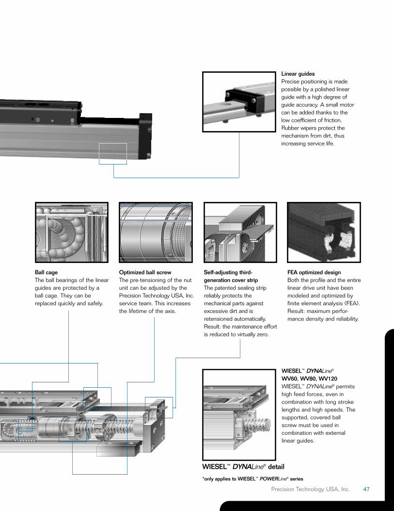
FEA optimized designBoth the profile and the entirelinear drive unit have beenmodeled and optimized byfinite element analysis (FEA).Result: maximum perfor-mance density and reliability.
WIESEL™ DYNALine®
WV60, WV80, WV120WIESEL™ DYNALine® permitshigh feed forces, even in combination with long strokelengths and high speeds. Thesupported, covered ballscrew must be used incombination with externallinear guides.
Ball cageThe ball bearings of the linearguides are protected by aball cage. They can bereplaced quickly and safely.
Optimized ball screwThe pre-tensioning of the nutunit can be adjusted by thePrecision Technology USA, Inc.service team. This increasesthe lifetime of the axis.
Self-adjusting third-generation cover stripThe patented sealing strip reliably protects themechanical parts againstexcessive dirt and isretensioned automatically.Result: the maintenance effortis reduced to virtually zero.
Linear guidesPrecise positioning is madepossible by a polished linearguide with a high degree ofguide accuracy. A small motorcan be added thanks to thelow coefficient of friction.Rubber wipers protect themechanism from dirt, thusincreasing service life.
WIESEL™ DYNALine® detail
*only applies to WIESEL™ POWERLine® series
48 Precision Technology USA, Inc.
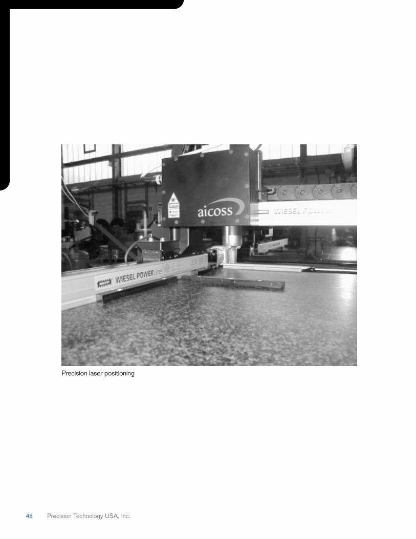
Precision laser positioning
49Precision Technology USA, Inc.
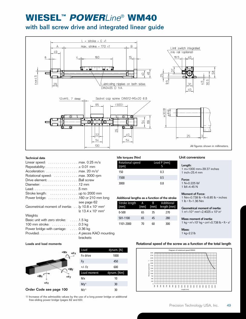
Technical dataLinear speed: . . . . . . . . . . . . . . . .max. 0.25 m/sRepeatability: . . . . . . . . . . . . . . . . .± 0.01 mmAcceleration: . . . . . . . . . . . . . . . . .max. 20 m/s2
Rotational speed: . . . . . . . . . . . . .max. 3000 rpmDrive element: . . . . . . . . . . . . . . . .Ball screwDiameter: . . . . . . . . . . . . . . . . . . .12 mmLead: . . . . . . . . . . . . . . . . . . . . . . .5 mmStroke length: . . . . . . . . . . . . . . .up to 2000 mmPower bridge: . . . . . . . . . . . . . . . .160 or 210 mm long
see page 62Geometrical moment of inertia: . . .ly 10.8 x 104 mm4
lz 13.4 x 104 mm4
WeightsBasic unit with zero stroke: . . . . .1.5 kg100 mm stroke: . . . . . . . . . . . . . .0.3 kgPower bridge with carriage: . . . . .0.36 kgProvided: . . . . . . . . . . . . . . . . . . . .4 pieces KAO mounting
brackets
Order Code see page 100
Loads and load moments
1) Increase of the admissible values by the use of a long power bridge or additionalfree-sliding power bridge (pages 62 and 63).
Rotational speed of the screw as a function of the total length
WIESEL™ POWERLine® WM40with ball screw drive and integrated linear guide
Load dynam. [N]
Fx drive 1000
Fy 450
+/- Fz 600
Load moment dynam. [Nm]
Mx 10
My1) 30
Mz1) 30
Idle torques [Nm]
Rotational speed Lead P [mm][rpm] 5
150 0.3
1500 0.5
3000 0.8
Additional lengths as a function of the stroke
Stroke length A B Additional[mm] [mm] [mm] length [mm]
0-500 65 35 270
501-1100 65 45 280
1101-2000 70 60 300
All figures shown in millimeters.
Unit conversions
Length:1 m=1000 mm=39.37 inches1 inch=25.4 mm
Force:1 N=0.225 lbf1 lbf=4.45 N
Moment of Force:1 Nm=0.738 lb • ft=8.85 lb • inches1 lb • ft=1.36 Nm
Geometrical moment of inertia:1 m4=1012 mm4=2.4025 x 10⁶ in4
Mass moment of inertia:1 kg • m2=104 kg • cm2=0.738 lb • ft • s2
Mass:1 kg=2.2 lb
50 Precision Technology USA, Inc.
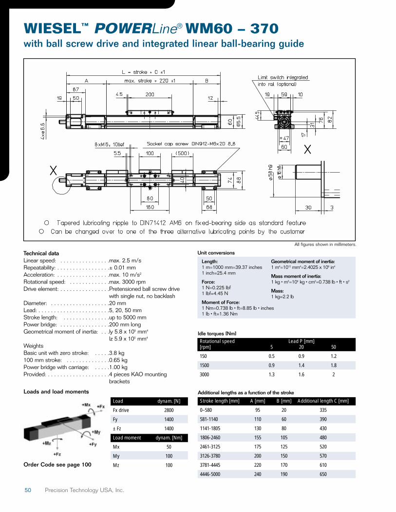
Technical dataLinear speed: . . . . . . . . . . . . . . . .max. 2.5 m/sRepeatability: . . . . . . . . . . . . . . . . .± 0.01 mmAcceleration: . . . . . . . . . . . . . . . . .max. 10 m/s2
Rotational speed: . . . . . . . . . . . . .max. 3000 rpmDrive element: . . . . . . . . . . . . . . . .Pretensioned ball screw drive
with single nut, no backlashDiameter: . . . . . . . . . . . . . . . . . . .20 mmLead: . . . . . . . . . . . . . . . . . . . . . . .5, 20, 50 mmStroke length: . . . . . . . . . . . . . . .up to 5000 mmPower bridge: . . . . . . . . . . . . . . . .200 mm longGeometrical moment of inertia: . . .ly 5.8 x 105 mm4
lz 5.9 x 105 mm4
WeightsBasic unit with zero stroke: . . . . .3.8 kg100 mm stroke: . . . . . . . . . . . . . .0.65 kgPower bridge with carriage: . . . . .1.00 kgProvided: . . . . . . . . . . . . . . . . . . . .4 pieces KAO mounting
brackets
Order Code see page 100
Loads and load moments
WIESEL™ POWERLine® WM60 – 370with ball screw drive and integrated linear ball-bearing guide
Load dynam. [N]
Fx drive 2800
Fy 1400
± Fz 1400
Load moment dynam. [Nm]
Mx 50
My 100
Mz 100
Idle torques [Nm]Rotational speed Lead P [mm][rpm] 5 20 50
150 0.5 0.9 1.2
1500 0.9 1.4 1.8
3000 1.3 1.6 2
Additional lengths as a function of the stroke
Stroke length [mm] A [mm] B [mm] Additional length C [mm]
0–580 95 20 335
581-1140 110 60 390
1141-1805 130 80 430
1806-2460 155 105 480
2461-3125 175 125 520
3126-3780 200 150 570
3781-4445 220 170 610
4446-5000 240 190 650
Length:1 m=1000 mm=39.37 inches1 inch=25.4 mm
Force:1 N=0.225 lbf1 lbf=4.45 N
Moment of Force:1 Nm=0.738 lb • ft=8.85 lb • inches1 lb • ft=1.36 Nm
Geometrical moment of inertia:1 m4=1012 mm4=2.4025 x 10⁶ in4
Mass moment of inertia:1 kg • m2=104 kg • cm2=0.738 lb • ft • s2
Mass:1 kg=2.2 lb
All figures shown in millimeters.
Unit conversions
51Precision Technology USA, Inc.
WIESEL™ POWERLine® WM60with ball screw drive and integrated linear ball-bearing guide
Technical dataLinear speed: . . . . . . . . . . . . . . . .max. 2.5 m/sRepeatability: . . . . . . . . . . . . . . . . .± 0.01 mmAcceleration: . . . . . . . . . . . . . . . . .max. 20 m/s2
Rotational speed: . . . . . . . . . . . . .max. 3000 rpmDrive element: . . . . . . . . . . . . . . . .Pretensioned ball screw driveDiameter: . . . . . . . . . . . . . . . . . . .20 mmLead: . . . . . . . . . . . . . . . . . . . . . . .5, 20, 50 mmStroke length: . . . . . . . . . . . . . . .up to 11.000 mm
with lead 50 mm max. 5000 mm
Power bridge: . . . . . . . . . . . . . . . .260 or 450 mm longsee page 62
Geometrical moment of inertia: . . .ly 5.8 x 105 mm4
lz 5.9 x 105 mm4
WeightsBasic unit with zero stroke: . . . . .6.16 kg100 mm stroke: . . . . . . . . . . . . . .0.64 kgPower bridge with carriage: . . . . .1.99 kgProvided: . . . . . . . . . . . . . . . . . . . .4 pieces KAO mounting
brackets
Order Code see page 100
Loads and load moments
1) Increase of the admissible values by the use of a long power bridge or additionalfree-sliding power bridge (pages 62 and 63).
Load dynam. [N]
Fx drive 4000
Fy 2000
± Fz 2000
Load moment dynam. [Nm]
Mx 100
My1) 200
Mz1) 200
Idle torques [Nm]Rotational speed Lead P [mm][rpm] 5 20 50
150 0.6 1.1 1.5
1500 1.1 1.8 2.3
3000 1.6 2.0 2.5
Additional lengths as a function of the stroke
Stroke length [mm] A [mm] B [mm] Additional length C [mm]
0–695 115 65 460
696-1335 165 115 560
1336-2075 185 135 600
2076-2780 210 160 650
2781-3545 230 180 690
3546-4285 250 200 730
4286-5015 275 225 780
Length:1 m=1000 mm=39.37 inches 1 inch=25.4 mm
Force:1 N=0.225 lbf1 lbf=4.45 N
Moment of Force:1 Nm=0.738 lb • ft=8.85 lb • inches1 lb • ft=1.36 Nm
Geometrical moment of inertia:1 m4=1012 mm4=2.4025 x 10⁶ in4
Mass moment of inertia:1 kg • m2=104 kg • cm2=0.738 lb • ft • s2
Mass:1 kg=2.2 lb
All figures shown in millimeters.
Unit conversions
52 Precision Technology USA, Inc.
Technical dataLinear speed: . . . . . . . . . . . . . . . .max. 2.5 m/sRepeatability: . . . . . . . . . . . . . . . . .± 0.01 mmAcceleration: . . . . . . . . . . . . . . . . .max. 20 m/s2
Rotational speed: . . . . . . . . . . . . .max. 3000 rpmDrive element: . . . . . . . . . . . . . . . .Pretensioned ball screw driveDiameter: . . . . . . . . . . . . . . . . . . .20 mmLead: . . . . . . . . . . . . . . . . . . . . . . .5 mmStroke length: . . . . . . . . . . . . . . .up to 10340 mm referred to
both power bridges. max. 5000 mmPower bridge: . . . . . . . . . . . . . . . .260 or 450 mm long
see page 62Geometrical moment of inertia: . . .ly 5.8 x 105 mm4
lz 5.9 x 105 mm4
WeightsBasic unit with zero stroke: . . . . .10.33 kg100 mm stroke: . . . . . . . . . . . . . .0.64 kgPower bridge with carriage: . . . . .1.99 kgProvided: . . . . . . . . . . . . . . . . . . . .4 pieces KAO mounting
brackets
Order Code see page 100
Loads and load moments
Load dynam. [N]
Fx drive 4000
Fy 2000
± Fz 2000
Load moment dynam. [Nm]
Mx 100
My 200
Mz 200
Additional lengths as a function of the stroke
Stroke length [mm] A [mm] B [mm] C [mm] X Y Z
0–1390 115 65 60 80 600 800
1391-2670 165 115 210 230 750 1050
2671-4150 185 135 250 270 790 1130
4151-5560 210 160 300 320 840 1230
Idle torques [Nm]Rotational speed Lead P [mm][rpm] 5
150 1.2
1500 2.2
3000 3.2
Note: For tube lengths of 5400 mm and over, the tubular profile iscomposed of two parts. The joint must be adequately supported. Itmay be possible to position the joint according to customer´s wishes.For screw leads > 20 mm, excess lengths cannot be implemented.
WIESEL™ POWERLine® WM60 – 500with ball screw drive and integrated linear ball-bearing guide in right/left execution
All figures shown in millimeters.
Length:1 m=1000 mm=39.37 inches 1 inch=25.4 mm
Force:1 N=0.225 lbf1 lbf=4.45 N
Moment of Force:1 Nm=0.738 lb • ft=8.85 lb • inches1 lb • ft=1.36 Nm
Geometrical moment of inertia:1 m4=1012 mm4=2.4025 x 10⁶ in4
Mass moment of inertia:1 kg • m2=104 kg • cm2=0.738 lb • ft • s2
Mass:1 kg=2.2 lb
Unit conversions

53Precision Technology USA, Inc.
WIESEL™ POWERLine® WM80 – 370with ball screw drive and integrated linear ball-bearing guide and short guide system
Technical dataLinear speed: . . . . . . . . . . . . . . . .max. 2.5 m/sRepeatability: . . . . . . . . . . . . . . . . .± 0.02 mmAcceleration: . . . . . . . . . . . . . . . . .max. 10 m/s2
Rotational speed: . . . . . . . . . . . . .max. 3000 rpmDrive element: Pretensioned ball screw with
single nut, no backlashDiameter: . . . . . . . . . . . . . . . . . . .25 mmLead: . . . . . . . . . . . . . . . . . . . . . . .5, 10, 20, 50 mmStroke length: . . . . . . . . . . . . . . .up to 5000 mm Power bridge: . . . . . . . . . . . . . . . .200 mm longGeometrical moment of inertia: . . .ly 1.9 x 106 mm4
lz 1.9 x 106 mm4
WeightsBasic unit with zero stroke: . . . . .7.00 kg100 mm stroke: . . . . . . . . . . . . . .1.10 kgPower bridge with carriage: . . . . .1.60 kgProvided: . . . . . . . . . . . . . . . . . . . .4 pieces KAO mounting
brackets
Order Code see page 100
Loads and load moments
Load dynam. [N]
Fx drive 3500
Fy 2100
± Fz 2100
Load moment dynam. [Nm]
Mx 150
My 180
Mz 180
Idle torques [Nm]Rotational speed Lead P [mm][rpm] 5 10 20 50
150 0.6 1.1 1.3 2.8
1500 1.1 1.5 1.6 2.2
3000 1.4 1.8 1.8 2.7
Additional lengths as a function of the stroke
Stroke length [mm] A [mm] B [mm] Additional length C [mm]
0–680 95 35 350
681-1310 125 80 425
1311-2065 150 105 475
2066-2830 170 125 515
2831-3590 195 150 565
3591-4355 215 170 605
4356-5000 235 190 645
All figures shown in millimeters.
Length:1 m=1000 mm=39.37 inches 1 inch=25.4 mm
Force:1 N=0.225 lbf1 lbf=4.45 N
Moment of Force:1 Nm=0.738 lb • ft=8.85 lb • inches1 lb • ft=1.36 Nm
Geometrical moment of inertia:1 m4=1012 mm4=2.4025 x 10⁶ in4
Mass moment of inertia:1 kg • m2=104 kg • cm2=0.738 lb • ft • s2
Mass:1 kg=2.2 lb
Unit conversions

54 Precision Technology USA, Inc.
WIESEL™ POWERLine® WM80with ball screw drive and integrated linear ball-bearing guide
Technical dataLinear speed: . . . . . . . . . . . . . . . .max. 2.5 m/sRepeatability: . . . . . . . . . . . . . . . . .± 0.01 mmAcceleration: . . . . . . . . . . . . . . . . .max. 20 m/s2
Rotational speed: . . . . . . . . . . . . .max. 3000 rpmDrive element: . . . . . . . . . . . . . . . .Pretensioned ball screw driveDiameter: . . . . . . . . . . . . . . . . . . .25 mmLead: . . . . . . . . . . . . . . . . . . . . . . .5, 10, 20, 50 mmStroke length: . . . . . . . . . . . . . . .up to 11.000 mm
with lead 50 mm max. 5000 mm
Power bridge: . . . . . . . . . . . . . . . .280 or 450 mm longsee page 62
Geometrical moment of inertia: . . .ly 1.9 x 106 mm4
lz 1.9 x 106 mm4
WeightsBasic unit with zero stroke: . . . . .11.57 kg100 mm stroke: . . . . . . . . . . . . . .1.08 kgPower bridge with carriage: . . . . .4.26 kgProvided: . . . . . . . . . . . . . . . . . . . .4 pieces KAO mounting
brackets
Order Code see page 100
Loads and load moments
1) Increase of the admissible values by the use of a long power bridge or additionalfree-sliding power bridge (pages 62 and 63).
Load dynam. [N]
Fx drive 5000
Fy 3000
± Fz 3000
Load moment dynam. [Nm]
Mx 350
My1) 300
Mz1) 300
Idle torques [Nm]Rotational speed Lead P [mm][rpm] 5 10 20 50
150 0.8 1.4 1.6 2.3
1500 1.4 1.9 2.0 2.8
3000 1.8 2.3 2.3 3.4
Additional lengths as a function of the stroke
Stroke length [mm] A [mm] B [mm] Additional length C [mm]
0–780 120 80 500
781-1535 170 125 595
1536-2375 190 145 635
2376-3205 215 170 685
3206-4045 235 190 725
4046-4885 255 210 765
4886-5000 280 235 815
All figures shownin millimeters.
Note: For tube lengths of 5400 mm and over, the tubular profile iscomposed of two parts. The joint must be adequately supported. Itmay be possible to position the joint according to customer´s wishes.For screw leads > 20 mm, excess lengths cannot be implemented.
Length:1 m=1000 mm=39.37 inches 1 inch=25.4 mm
Force:1 N=0.225 lbf1 lbf=4.45 N
Moment of Force:1 Nm=0.738 lb • ft=8.85 lb • inches1 lb • ft=1.36 Nm
Geometrical moment of inertia:1 m4=1012 mm4=2.4025 x 10⁶ in4
Mass moment of inertia:1 kg • m2=104 kg • cm2=0.738 lb • ft • s2
Mass:1 kg=2.2 lb
Unit conversions

55Precision Technology USA, Inc.
WIESEL™ POWERLine® WM120with ball screw drive and integrated linear ball-bearing guide
Technical dataLinear speed: . . . . . . . . . . . . . . . .max. 2.0 m/sRepeatability: . . . . . . . . . . . . . . . . .± 0.01 mmAcceleration: . . . . . . . . . . . . . . . . .max. 20 m/s2
Rotational speed: . . . . . . . . . . . . .max. 3000 rpmDrive element: . . . . . . . . . . . . . . . .Pretensioned ball screw driveDiameter: . . . . . . . . . . . . . . . . . . .32 mmLead: . . . . . . . . . . . . . . . . . . . . . . .5, 10, 20, 40 mmStroke length: . . . . . . . . . . . . . . .up to 11.000 mm
with lead 40 mm max. 5000 mm
Power bridge: . . . . . . . . . . . . . . . .320 or 500 mm longsee page 62
Geometrical moment of inertia: . . .ly 7.7 x 106 mm4
lz 9.4 x 106 mm4
WeightsBasic unit with zero stroke: . . . . .25.91 kg100 mm stroke: . . . . . . . . . . . . . .1.93 kgPower bridge with carriage: . . . . .9.25 kgProvided: . . . . . . . . . . . . . . . . . . . .4 pieces KAO mounting
brackets
Order Code see page 100
Loads and load moments
Load dynam. [N]
Fx drive 12000
Fx drive 3240 8000
Fy 6000
± Fz 6000
Load moment dynam. [Nm]
Mx 500
My 600
Mz 600
Idle torques [Nm]Rotational speed Lead P [mm][rpm] 5 10 20 40
150 1.2 2.1 1.8 2.4
1500 2.3 3.0 2.8 3.6
3000 2.8 3.8 3.5 4.0
Additional lengths as a function of the stroke
Stroke length [mm] A [mm] B [mm] Additional length C [mm]
0–890 155 100 595
891-1695 225 170 735
1696-2625 260 205 805
2626-3555 295 240 875
3556-4485 330 275 945
4486-5000 365 310 1015
All figures shown in millimeters.
Length:1 m=1000 mm=39.37 inches 1 inch=25.4 mm
Force:1 N=0.225 lbf1 lbf=4.45 N
Moment of Force:1 Nm=0.738 lb • ft=8.85 lb • inches1 lb • ft=1.36 Nm
Geometrical moment of inertia:1 m4=1012 mm4=2.4025 x 10⁶ in4
Mass moment of inertia:1 kg • m2=104 kg • cm2=0.738 lb • ft • s2
Mass:1 kg=2.2 lb
Unit conversions
56 Precision Technology USA, Inc.
WIESEL™ POWERLine®
Guide tube
WM40-190
WM60-190
All figures shown in millimeters.
All figures shown in millimeters.
Length: 1 m=1000 mm=39.37 inches1 inch=25.4 mm
Force: 1 N=0.225 lbf1 lbf=4.45 N
Moment of Force: 1 Nm=0.738 lb • ft=8.85 lb • inches1 lb • ft=1.36 Nm
Geometrical moment of inertia: 1 m4=1012 mm4=2.4025 x 10⁶ in4
Mass moment of inertia: 1 kg • m2=104 kg • cm2=0.738 lb • ft • s2
Mass: 1 kg=2.2 lb
Unit conversions Order Code see page 100

57Precision Technology USA, Inc.
WIESEL™ POWERLine®
Guide tube
WM80-190
WM120-190
All figures shown in millimeters.
All figures shown in millimeters.
All figures shownin millimeters.
All figures shown in millimeters.
Length: 1 m=1000 mm=39.37 inches1 inch=25.4 mm
Force: 1 N=0.225 lbf1 lbf=4.45 N
Moment of Force: 1 Nm=0.738 lb • ft=8.85 lb • inches1 lb • ft=1.36 Nm
Geometrical moment of inertia: 1 m4=1012 mm4=2.4025 x 10⁶ in4
Mass moment of inertia: 1 kg • m2=104 kg • cm2=0.738 lb • ft • s2
Mass: 1 kg=2.2 lb
Unit conversions Order Code see page 100

61Precision Technology USA, Inc.
Accessories for WIESEL™ POWERLine®
Mounting brackets
Dimension [mm]Size A B C D ø E F ø G HWM40 54 16 10 40 10 5.7 5.5 7WM/WV60 54 17.5 17 50 11 6.5 6.6 7WM/WV80 68 17.5 17 50 11 6.5 6.6 7WM/WV120 80 25 18 50 15 8.5 9 10WM40 System KAO 40 16 10 26 10 5.7 5.5 7WM60 System KAO 58 17.5 17 40 11 6.5 6.6 7
KAO Mounting bracketsThe WIESEL™ unit is secured to mounting surface by means ofthe KAO mounting brackets which are inserted in the grooves provided in the sides of the tubular aluminum profileand screwed onto the mounting surface with the aid of sockethead cap screws. The number of mounting brackets requireddepends on the load and overall length of the WIESEL™ unit.This is shown in the diagrams. Increasing side forces reducesthe distance between supports. Each unit is provided with 4pieces KAO Mounting brackets.
Maximum torque ofmounting screws
Size Moment [Nm]
WM40 7.3–12
WM/WV60 7.3–12
WM/WV80 7.3–12
WM/WV120 17–30
KAO System bracketsOnly needed for WH40. With multi-coordinate arrangementsof several WIESEL™ units, this can be used to mount aWIESEL™ directly to the power bridge of a unit positionedimmediately below.
Note: It is advisable to secure the linear drive unit at intervals of at least 750 mm. This ensures that all the permissible loads can be absorbedwithout significantly deforming the tubular aluminum profile.
Length: 1 m=1000 mm=39.37 inches1 inch=25.4 mm
Force: 1 N=0.225 lbf1 lbf=4.45 N
Moment of Force: 1 Nm=0.738 lb • ft=8.85 lb • inches1 lb • ft=1.36 Nm
Geometrical moment of inertia: 1 m4=1012 mm4=2.4025 x 10⁶ in4
Mass moment of inertia: 1 kg • m2=104 kg • cm2=0.738 lb • ft • s2
Mass: 1 kg=2.2 lb
Unit conversions Order Code see page 100

62 Precision Technology USA, Inc.
Accessories for WIESEL™ POWERLine®
Long power bridge
LKB Long power bridgeThe long power bridge increases themaximum permissible load moments My andMz of a WIESEL™ unit without requiring tostep up a size. The difference in length between the long power bridge and thestandard power bridge must be taken intoaccount when calculating the overall lengthof the WIESEL™ unit.
Overall length of the WIESEL™ unit:
Ltot = Stroke + C + ∆Kb
C* = Specific additional lengthLtot = Overall length WIESEL™ unitStroke = Required stroke length ∆Kb = Difference in length between long
and standard power bridge
Size Length of power bridge My Mz[mm] [Nm] [Nm]
WM40-000 210 50 50WM60-000 450 500 500WM80-000 450 750 750WM120-000 500 1500 1500
Note: All other limit values are comparable to those of versions with standard power bridge. High load moments lead to major deformation of thetubular aluminum profile. The distance between supports should be reduced on order to minimize this deformation.
Note: All other limit values according to executions with standard power bridge.
WM60
WM80
WM120
WM40
All figures shown in millimeters.
* Calculation in depency of stroke and ∆Kb. The dimensionC is shown in the charts oftechnical data of the corresponding actuator.
Length: 1 m=1000 mm=39.37 inches1 inch=25.4 mm
Force: 1 N=0.225 lbf1 lbf=4.45 N
Moment of Force: 1 Nm=0.738 lb • ft=8.85 lb • inches1 lb • ft=1.36 Nm
Geometrical moment of inertia: 1 m4=1012 mm4=2.4025 x 10⁶ in4
Mass moment of inertia: 1 kg • m2=104 kg • cm2=0.738 lb • ft • s2
Mass: 1 kg=2.2 lb
Unit conversions Order Code see page 100
63Precision Technology USA, Inc.
Accessories for WIESEL™ POWERLine®
Additional free-sliding power bridge
OKB Additional free-sliding power bridgeThe additional free-sliding power bridge provides:• Individual increase of the load moments My and Mz of a
WIESEL™ unit. Load moment My is limited by force ± Fz;Mz is limited by force ±Fy.
• Longer and therefore improved guidance.• Particularly suitable as a vertical guide and lifting module.
The required center distance between the driven and thefree-sliding power bridge is calculated as follows:
LA = Distance between center of driven power bridge andcenter of free-sliding power bridge [mm]
M = Load moment My or Mz [mm] Fmax = Maximum force Fz or Fy of the WIESEL™ unit
concerned [N]
The center distance between the two power bridges must betaken into account when calculating the overall length of theWIESEL™ unit.
Lc = Specific additional length [mm] between long and standard power bridge. (see technical data of the respective WIESEL™)
LA = MFmax
Overall length of WIESEL™ unit Ltot = Stroke + LC + LA
Minimum center distance between driven and free-slidingpower bridge (given for standard power bridge).
Size LA [mm]WM40* min 175 max 600WM60 335WM80 360WM120 450
The required force to move the additional free sliding powerbridge must be taken into account when selecting the drive.
*For stroke lengths of more than 1700 mm please contact our productspecialists for the maximum screw rotational speed.
Size F [N]WM40 40WM60 200WM80 250WM120 300
Note: High load moments lead to major deformation of the tubularaluminum profile. In order to minimize this deformation, the distance between the fixing points should be reduced.
Length: 1 m=1000 mm=39.37 inches1 inch=25.4 mm
Force: 1 N=0.225 lbf1 lbf=4.45 N
Moment of Force: 1 Nm=0.738 lb • ft=8.85 lb • inches1 lb • ft=1.36 Nm
Geometrical moment of inertia: 1 m4=1012 mm4=2.4025 x 10⁶ in4
Mass moment of inertia: 1 kg • m2=104 kg • cm2=0.738 lb • ft • s2
Mass: 1 kg=2.2 lb
Unit conversions Order Code see page 100

64 Precision Technology USA, Inc.
Accessories for WIESEL™ POWERLine®
Bevel gearbox
KRG Bevel gearboxBevel gearboxes are used toinstall a motor at right angles tothe linear drive unit or to operate two linear drive units in parallel.
Direction of rotation
Direction of rotation – Motor right
Direction of rotation – Motor left
65Precision Technology USA, Inc.
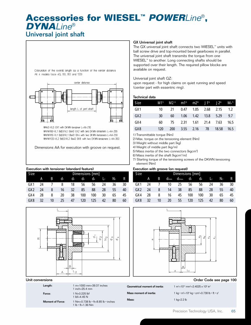
Accessories for WIESEL™ POWERLine®,DYNALine®
Universal joint shaftGX Universal joint shaftThe GX universal joint shaft connects two WIESEL™ units withball screw drive and top-mounted bevel gearboxes in parallel.The universal joint shaft transmits the torque from oneWIESEL™ to another. Long connecting shafts should besupported over their length. The required pillow blocks areavailable on request.
Universal joint shaft GZ:upon request - for high claims on quiet running and speed(center part with essentric ring).
Size M11) M2 2) m13) m24) J15) J26) MA7)
GX1 10 21 0.47 1.05 2.68 2.15 1.2
GX2 30 60 1.06 1.42 13.8 5.29 9.7
GX4 60 75 2.31 1.61 21.4 7.63 16.5
GX8 120 200 3.55 2.16 78 18.58 16.51) Transmittable torque [Nm]2) Max. torque on the tensioning element [Nm]3) Weight without middle part [kg] 4) Weight of middle part [kg/m]5) Mass inertia of the two connectors [kgcm2]6) Mass inertia of the shaft [kgcm2/m]7) Starting torque of the tensioning screws of the DKWN tensioning
element [Nm]
Technical data
Size Dimensions [mm]A B d2min. d2max. d3 d4 L2 N2 R
GX1 24 7 10 25 56 56 24 36 30GX2 24 8 14 38 85 88 28 55 40GX4 28 8 16 45 100 100 30 65 45GX8 32 10 20 55 120 125 42 80 60
Size Dimensions [mm]A B d1 d2 d3 d4 L2 N2 R
GX1 24 7 8 18 56 56 24 36 30GX2 24 8 16 32 85 88 28 55 40GX4 28 8 20 38 100 100 30 65 45GX8 32 10 25 47 120 125 42 80 60
Execution with tensioner (standard feature) Execution with groove (on request)
Dimensions AA for execution with groove on request.
Length: 1 m=1000 mm=39.37 inches1 inch=25.4 mm
Force: 1 N=0.225 lbf1 lbf=4.45 N
Moment of Force: 1 Nm=0.738 lb • ft=8.85 lb • inches1 lb • ft=1.36 Nm
Geometrical moment of inertia: 1 m4=1012 mm4=2.4025 x 10⁶ in4
Mass moment of inertia: 1 kg • m2=104 kg • cm2=0.738 lb • ft • s2
Mass: 1 kg=2.2 lb
Unit conversions Order Code see page 100
66 Precision Technology USA, Inc.
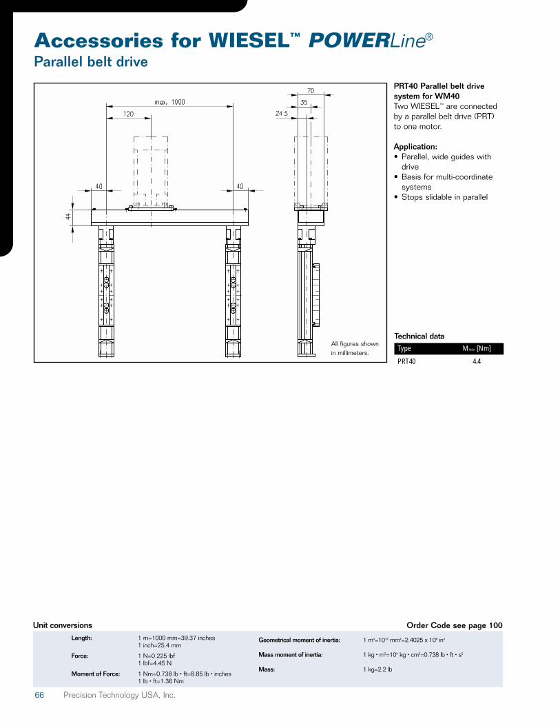
Accessories for WIESEL™ POWERLine®
Parallel belt drive
PRT40 Parallel belt drivesystem for WM40Two WIESEL™ are connectedby a parallel belt drive (PRT)to one motor.
Application:• Parallel, wide guides with
drive• Basis for multi-coordinate
systems• Stops slidable in parallel
All figures shownin millimeters.
Technical dataType Mmax [Nm]
PRT40 4.4
Length: 1 m=1000 mm=39.37 inches1 inch=25.4 mm
Force: 1 N=0.225 lbf1 lbf=4.45 N
Moment of Force: 1 Nm=0.738 lb • ft=8.85 lb • inches1 lb • ft=1.36 Nm
Geometrical moment of inertia: 1 m4=1012 mm4=2.4025 x 10⁶ in4
Mass moment of inertia: 1 kg • m2=104 kg • cm2=0.738 lb • ft • s2
Mass: 1 kg=2.2 lb
Unit conversions Order Code see page 100
67Precision Technology USA, Inc.
Accessories for WIESEL™ POWERLine®,DYNALine®
Timing belt driveRT Belt driveThe RT 40/60/80 belt drive isa transmission designed to minimize the overall length. The RT housing (which is bothbelt guard and motor support)can be mounted in positionsoffset by 90°. The drive is provided via standard toothbelt drives.
Transmission ratios of i = 1 : 1and i = 2 : 1 are possible.(RT 40 only i = 1:1)
Mmax = Maximum torque at the output shaft [Nm]nmax = Maximum input speed [rpm]Midle = Idle torque [Nm]J = Mass inertia referred to input shaft [kgcm2]
Technical data
Size Mmax nmaxinput Midle Efficiency η Mass inertia J [kgcm2] Weight [kg]
[Nm] [rpm] [Nm] 1 : 1 1 : 1RT40 1.75 3000 app. 0.3 0.8 0.25 0.62
All figures shown in millimeters.
Technical data
Size Mmax nmaxinput Midle Efficiency η Mass inertia J [kgcm2] Weight [kg]
[Nm] [rpm] [Nm] 1 : 1 2 : 1 1 : 1 2 : 1RT60 15 3000 app. 0.7 0.85 4.38 10.11 5.6 7.1RT80 30 3000 app. 0.7 0.85 4.65 10.38 5.5 7.0
All figures shown in millimeters.
RT40
RT60/80
Length: 1 m=1000 mm=39.37 inches1 inch=25.4 mm
Force: 1 N=0.225 lbf1 lbf=4.45 N
Moment of Force: 1 Nm=0.738 lb • ft=8.85 lb • inches1 lb • ft=1.36 Nm
Geometrical moment of inertia: 1 m4=1012 mm4=2.4025 x 10⁶ in4
Mass moment of inertia: 1 kg • m2=104 kg • cm2=0.738 lb • ft • s2
Mass: 1 kg=2.2 lb
Unit conversions Order Code see page 100
68 Precision Technology USA, Inc.
Accessories for WIESEL™ POWERLine®,DYNALine®
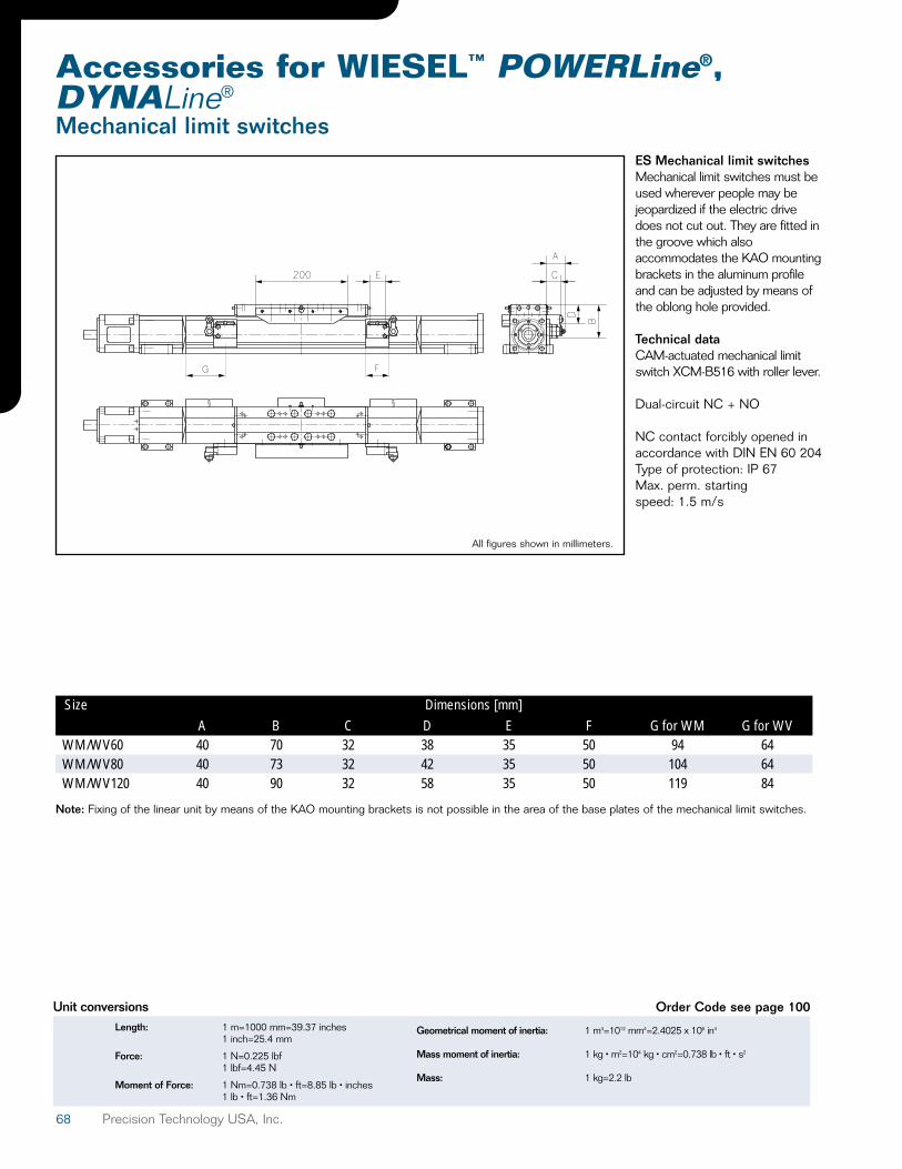
Mechanical limit switchesES Mechanical limit switchesMechanical limit switches must beused wherever people may bejeopardized if the electric drivedoes not cut out. They are fitted inthe groove which alsoaccommodates the KAO mountingbrackets in the aluminum profileand can be adjusted by means ofthe oblong hole provided.
Technical dataCAM-actuated mechanical limitswitch XCM-B516 with roller lever.
Dual-circuit NC + NO
NC contact forcibly opened inaccordance with DIN EN 60 204Type of protection: IP 67Max. perm. starting speed: 1.5 m/s
A B C D E F G for WM G for WVWM/WV60 40 70 32 38 35 50 94 64WM/WV80 40 73 32 42 35 50 104 64WM/WV120 40 90 32 58 35 50 119 84
Size Dimensions [mm]
Note: Fixing of the linear unit by means of the KAO mounting brackets is not possible in the area of the base plates of the mechanical limit switches.
Length: 1 m=1000 mm=39.37 inches1 inch=25.4 mm
Force: 1 N=0.225 lbf1 lbf=4.45 N
Moment of Force: 1 Nm=0.738 lb • ft=8.85 lb • inches1 lb • ft=1.36 Nm
Geometrical moment of inertia: 1 m4=1012 mm4=2.4025 x 10⁶ in4
Mass moment of inertia: 1 kg • m2=104 kg • cm2=0.738 lb • ft • s2
Mass: 1 kg=2.2 lb
Unit conversions Order Code see page 100
All figures shown in millimeters.

69Precision Technology USA, Inc.
Accessories for WIESEL™ POWERLine®,DYNALine®
Shaft encoder attachment
IG601 mounted on WM/WV60
IG601 mounted on WM/WV80
IG601 mounted on WM/WV120
IG601 mounted on WM40 ADG Shaft encoder attachmentfor POWERLine® with ballscrew drive on moveablebearing sideShaft encoder attachment forPOWERLine® with tooth beltdrive see page 92.
Incremental shaft encoderscan be used in combinationwith screws to measuredisplacement. This is achievedby mounting the shaft encoderon the movable bearing end ofthe WIESEL™ shaft. IG601incremental shaft encoderswith pulse counts between100 and 2500 are used byPrecision Technology USA, Inc.,as standard elements.
Two output circuits are basicallypossible:GE = Push-pull output, 10–30 VLD = Line Driver, antivalent, as
per RS 422 (5 V ± 10%)
Detailed information can befound on page 92.
The shaft encoder is connectedto the WIESEL™ via a two-pieceadapter flange and a coupling. Itcan be adjusted to the requiredreference point (1) by looseningthe threaded studs.
Absolute-value encoderson request.
All figures shown in millimeters.
All figures shown in millimeters.
All figures shown in millimeters.
All figures shown in millimeters.
Length: 1 m=1000 mm=39.37 inches1 inch=25.4 mm
Force: 1 N=0.225 lbf1 lbf=4.45 N
Moment of Force: 1 Nm=0.738 lb • ft=8.85 lb • inches1 lb • ft=1.36 Nm
Geometrical moment of inertia: 1 m4=1012 mm4=2.4025 x 10⁶ in4
Mass moment of inertia: 1 kg • m2=104 kg • cm2=0.738 lb • ft • s2
Mass: 1 kg=2.2 lb
Unit conversions Order Code see page 100