mechanical engineering news - plantdesignsolutions.com · as the manual data transfer is...
TRANSCRIPT
Mec
hani
cal
Engi
neer
ing
New
s
FOR THE POWER,
PROCESS AND
RELATED INDUSTRIES
The COADE Mechanical EngineeringNews Bulletin is published twice a yearfrom the COADE offices in Houston,Texas. The Bulletin is intended to provideinformation about software applicationsand development for MechanicalEngineers serving the power, process andrelated industries. Additionally, the Bulletinserves as the official notificationvehicle for software errors discovered inthose Mechanical Engineering programsoffered by COADE.
©2003 COADE, Inc. All rights reserved.
V O L U M E 3 4 J U L Y 2 0 0 3
What’s New at COADE
CodeCalc and PVElite New Features .......... 1COADE Releases CADWorx EQUIPMENT .. 3COADE Announcement Procedures .............. 4Graphics Speed Issues .................................. 5Exporting Output to MS Word ........................ 7CAESAR II Version 4.50 ................................ 8CADWorx 2004............................................ 23
Technology You Can Use
Integration of Tubesheet and ExpansionJoint Analysis ............................................. 9
Satisfying Expansion Load CaseRequirements .......................................... 11
Mass Spacing for Dynamic Analysis ............ 13Assessing the Metal Loss Flaws using
API Recommended Practice 579 ............ 14PC Hardware/Software for the Engineering
User (Part 34) ......................................... 18
Program Specifications
CAESAR II Notices ...................................... 20
TANK Notices .............................................. 22
CodeCalc Notices ........................................ 22
PVElite Notices ............................................ 23
I N T H I S I S S U E :
New Features in CodeCalc 6.5and PVElite 5.0
(by: Mandeep Singh)
CodeCalc version 6.5 (also included in PVElite version 5.0) was released inJanuary 2003 and has many new features. Some of the new capabilities arelisted below:
Enhancements in the TEMA Tubesheet module in CodeCalc 6.5
In this version, the tubesheet module and the thick (flanged and flued)expansion joint modules were integrated. The tubesheet module contains theinput for the expansion joint. This makes analyzing a fixed tubesheet with anexpansion joint, quicker and easier. As the manual data transfer is eliminated,the chances of error are also reduced. See the article Integration of Tubesheetand Expansion Joint also in this newsletter.
> continued on p.2
CADWorxEquipment> see story page 3
Problems Exportingto Word> see story page 7
CAESAR II 4.50> see story page 8
API-579> see story page 14
Dealing with Spam> see story page 19
CADWorx 2004> see story page 23

COADE Mechanical Engineering News July 2003
2
CodeCalc version 6.5 also includes PD 5500 tubesheet rules (Britishcode), for u-tube, fixed and floating tubesheets.
Modifications were also made in the calculation of required fixedtubesheet thickness, to properly account for the non-linearity in itsformula. In previous versions it may have been necessary to manuallyiterate on a required thickness. Now, CodeCalc performs thisiteration automatically. Improvements were also made in U-tubeand fixed tubesheet summaries.
Fitness for Service using API 579
CodeCalc 6.5 implements API 579 Sections 4 and 5 coveringLevel 1 and Level 2 flaw assessments for metal loss on cylindricalshells, simple cones, and formed heads. Another article in thisnewsletter has an in-depth discussion of this capability with asolved example.
Fitness for Service (FFS) assessment using API RecommendedPractice 579 is performed to assess the operation, safety andreliability of the process plant equipment, such as pressure vessels,piping and tanks for some desired future period. The assessmentprocedure provides an estimate of the remaining strength of theequipment in its current state, which may have been degraded whilein-service from its original condition.
Color Syntax Highlighting in the Output Reports
Color has been added to the output reports to highlight importantvalues, thus increasing the readability of the reports. Importantnotes appear in blue while headings are in bold and failures/warnings/errors are indicated in red color. This feature was added in the April4th build of CodeCalc and PVElite.
The color highlighting is also preserved when printing these reportsand when exporting to MS Word.
Enhancement in the Nozzle module
For hillside or other non-central nozzles on elliptical or torisphericalheads, the program now prints a warning if the nozzle is outside thespherical portion of the head and the user has indicated otherwise.
A “small” nozzle is nozzle that does not require an area replacementcalculation due to its smaller size. But, some “small” nozzles thatare in close proximity to each other may require these calculations.In this version, the switch to force the program to perform areareplacement calculation on “small” nozzle was moved from the filelevel to each individual nozzle input.
Added WRC 107 Auto-calc on support lug
An option was added in the support lug dialog to perform WRC-107calculations without leaving the Leg Lug module. See the dialog inthe figure below.
In the shell, nozzle and flange modules input errors (if any) are nowdisplayed on the screen at the time of input. Here is an example:
The ASME Material database now displays the “Class/Thickness”of materials in the list view. This will help in finding the rightmaterial when more than one occurrence of a material is listed in theASME database.

July 2003 COADE Mechanical Engineering News
3
A few of the new features in PVElite version 5.0 are:
• Enhancements listed in the CodeCalc part.
• Added ASME A-2002 updates, including revision to materialdatabases
• Integrated 3D graphics into Input
• Added option to model Sump Elements
• Added Nozzle on Nozzle capability
• Implemented export to ODBC database (MS Access)
• Added OD basis support is for Division 1, vessels
• Added color syntax highlighting in the output, e.g. questionableresults are shown in red color
• Added PD:5500 (British code) Annex C, fluctuating pressurefatigue analysis
• Added criterion of PD:5500 category C vessels
• Added bolting requirements for Horizontal vessels
• Added on screen calculations for Nozzle Weld sizes and aWRC 107 scratch pad
• Enhancements to the load case combinations for longitudinalstress
• Added option for 0.90*Yield for hydro-test allowable (Div 1)
• Added weld sizes for basering chair caps
• Improvements to the MS Word report generation
• Major update of the printed documentation.
COADE Releases CADWorxEQUIPMENT
(by: Scott Nickel)
COADE has announced the release of the latest module in itsCADWorx 2004 Plant Design Suite, CADWorx EQUIPMENT.CADWorx EQUIPMENT adds the ability to quickly and easilycreate AutoCAD-based 3D models of equipment — horizontal orvertical, single or multi-state vessels, heat exchangers and pumps— to the piping, P&ID, structural steel, HVAC, and instrumentloops capabilities already available with CADWorx 2004.
CADWorx EQUIPMENT works on a hierarchal basis. The processbegins by identifying the equipment’s component parts, such as avessel’s heads, shells, nozzles and supports, via icons selected fromthe toolbar. Entering required dimensional data in the propertyeditor instantly, parametrically updates the model. Equipmentcomponents, or details on the components, can be “cut and pasted”for easy modeling and modification of equipment. Selection listscontaining flange ratings, flange facings, motor frames and moreare available from the program’s property editor.
COADE has long been on the forefront of the industry as far asCAD-to-analysis integration is concerned, with its CADWorx PIPEto CAESAR II seamless bi-directional interface. The same strategyis brought to CADWorx EQUIPMENT, which offers a seamless,bi-directional interface between vessel models built in this moduleand PVElite, COADE’s vessel analysis software. A vessel built inCADWorx EQUIPMENT may be exported to a native PVElitefile, analyzed and modified, and then re-imported to ensure that allchanges made during the analysis process are reflected back into theCAD model. Likewise, any vessel built in PVElite may be used togenerate a 3D CAD model in CADWorx EQUIPMENT, ensuringaccuracy and saving modeling time.

COADE Mechanical Engineering News July 2003
4
Vessel in CADWorx/Equipment
Same Vessel transferred into PVElite
COADE Announcement Procedures(by: Richard Ay)
In an effort to keep all users informed of software releases, softwareupdates, and other important occurrences, COADE directly e-mailsregistered users. This e-mail process is controlled by a web-basedList Server. This procedure was introduced in the February 2002issue of this newsletter. There are several important points to noteabout this announcement procedure.
How do you register for this service?
From the “Help” menu of COADE’s engineering products, and the“Pipe” menu of the CADWorx application, is a link for “On-LineRegistration”. Additionally, the first time you run the softwarefollowing an installation, you are prompted to register. Eitheralternative takes you to a web page for you to fill in your contactinformation. Once completed, this information is stored on a ListServer. (This List Server is maintained by a third party. COADEdoes not maintain this server.) If you don’t register, you will notreceive our announcements.
When registering, if you have the capability to receive HTML e-mail, you should check the appropriate checkbox indicating this.The HTML e-mails are laid out better, and are more informativethan the plain text messages.
How do you update your information?
When your contact information (such as e-mail address) changes,you can follow the link at the bottom of any announcement to accessyour profile on the List Server. You should then make the necessarychanges to your profile.
What should you do if you no longer want COADE notices?
If at some point you decide you no longer want to receive COADEannouncements, you can follow the link at the bottom of anyannouncement to access your profile on the List Server. You canthen “opt out” of future announcements.
Please do not “reply” to the announcements:
The e-mail announcements sent by the List Server contain a returnaddress of [email protected]. This is not a real e-mail address. Weeventually do get the reply, but these responses are directed to anun-attended mailbox. The announcement itself includes the propercontact information if you need to communicate directly withCOADE.
July 2003 COADE Mechanical Engineering News
5
What should you do if you registered, but don't receiveannouncements?
Every time an announcement is distributed, we learn from the ListServer that roughly 10% of the messages bounced back. Thisindicates bad or changed user e-mail addresses. When twoconsecutive messages bounce, the List Serve deletes the offendingprofile from its database. This means that you will no longerreceive COADE announcements, even though you think you areregistered. In effect, the List Server un-registered your profile.
If you suspect this may have happened, please register again, asdescribed above.
We are hoping that the use of this List Server provides an additionalservice to our users. However, the success of this service dependson users maintaining their correct contact information.
Graphics Speed Issues(by: Richard Ay)
COADE’s engineering programs (CAESAR II, PVElite, andCodeCalc) utilize the HOOPS 3D graphics engine. This engine is3rd party software, not developed by COADE. Using a 3rd partygraphics engine provides a number of benefits to users:
• State of the art graphics technology (such as renderingand calculations in hardware)
• Faster implementation of the advances in new hardware
• Provides a more uniform handling of graphics across avariety of operating systems
However, the draw back to using a 3rd party package is that thesoftware is limited to the performance and capabilities of the 3rd
party package. Recently, a number of CAESAR II users anddealers have expressed concern that these 3D graphics are slow.“Slow” is a relative term, slow compared to what?
Each release of CAESAR II since Version 4.20 has offered aHOOPS speed improvement of at least 40%. These improvementsare due to optimization of the CAESAR II code (to take betteradvantage of the capabilities of the HOOPS library), andimprovements in the base HOOPS library.
In an attempt to provide specific answers to this question, severalperformance tests using the HOOPS 3D graphics were performedon a number of COADE computers. The details of the hardwareused can be found on the accompanying spreadsheet. Note that thetest machines encompassed a wide range of CPUs (from dual 300Mhz to single 2.8 Ghz) and a variety of graphics boards (from 8Mbytes to 128 Mbytes).
There are two groups of tests. The first set of tests used a“Performance Test” program from the HOOPS vendor. The testsperformed here consisted of drawing simple shapes and text, overand over again, in various positions. These tests indicate that thebetter your graphics board, especially the more graphics memoryavailable, the better the performance.
The second set of tests consisted of plotting a number ofCAESAR II jobs on the test machines. The results of these testsshow the expected interaction between the CPU and graphicsboard. For example, the “dual 700 Mhz with 8 Mbyte graphicscard” performed better than all but one of the machines with asingle processor and 8 times the graphics memory! These testsindicate that in addition to a good graphics board, you also needeither a very fast single CPU, or dual CPUs of medium speed.
To illustrate the performance improvement made between differentversions of HOOPS, in the “CAESAR II tests”, a number of theresults are shown in “blue”, and are noted as “Ver 8.12”. Theseresults were obtained with the graphics released for CAESAR IIVersion 4.40 Build 030403, using the 8.12 version of the HOOPSlibrary. (Previous builds of CAESAR II Version 4.40 used the8.00 version of the HOOPS library.) Depending on the job, thespeed improved by a factor of from 4 to 30. This improvement canbe attributed to 8.12 version of HOOPS, which now draws moreprimitives directly using the hardware, instead of COADE drawingthem in software.
In addition, most video cards now have OpenGL built-in, whichallows HOOPS to push the rendering all the way down to thehardware, where before, most of the drawing had to be done withthe CPU. Video cards with a lot of memory have big z-buffers,plus good optimization, which helps them avoid drawing thingsthat will be obscured by objects “on top”. While the HOOPSlibrary and COADE software can improve and optimize, the bestperformance can be obtained only by also utilizing fast hardware.This is one of the key concepts to grasp. By default, HOOPSutilizes the OPENGL capabilities of your system. Utilizing graphicscards with good OPENGL acceleration will improve the overallperformance of the applications.
(CAESAR II users note that Version 4.50 will provide even fasterperformance. The model may be manipulated while it is beingdrawn.)

COADE Mechanical Engineering News July 2003
6
Setup A B C D E F
Machine DescriptionDual 700, 512Mbytes Ram
Dual 300 Mhz, 512Mbyte Ram
Dual 700 Mhz, 1Gbyte Ram
1.9 Ghz, 512Mbyte Ram
2.8 Ghz, 1Gbyte Ram
1Ghz, 512Mbyte Ram
Operating System Windows 2000 Windows 2000 Windows 2000 Windows XP Windows XP Windows 2000
Graphics Board Description
Diamond Multimedia Fire Gl 1000 Pro, 8Mbytes, AGP
AccelStar II, 8Mbytes, AGP
Winfast A170, 64Mbytes, AGP
Nvidia GeForce2 Mx400, 64Mbytes, AGP
Nvidia GeForce4 MX 440, 64Mbytes, AGP
Radeon 9000 IF Pro, 128Mbytes, AGP
Techsoft Test2) 3D Edges/sec 33,865 30,059 1,164,189 114,472 227,625 1,308,5524) 3D markers/sec 40,355 49,556 1,717,821 222,819 226,387 1,460,2147) 3D polygons/sec 17,338 15,039 554,454 143,572 215,665 802,499
8) 3D edgeless polygons/sec 26,905 26,765 934,892 215,138 413,939 1,265,0789) 3D lit edgeless polygons/sec 79,421 24,585 807,252 216,095 414,924 1,119,36511) 3D hello worlds/sec 2,662 3,364 17,000 18,832 27,546 32,86914) unlit shells/sec 875 981 46,531 3,895 7,732 44,26315) flat lit shells/sec 863 879 37,923 3,894 7,732 41,03916) gouraud lit shells/sec 819 826 36,428 3,893 7,771 39,117
Techsoft Test Notes:1) Test results were obtained using Techsoft's performance test program "PT.EXE".2) On all machines, the PT.EXE options of double buffering and culling were turned on.3) Of the 16 tests performed, only those noted above were compared.4) Tests results shown in red are those functions used most by COADE products.
CAESAR II TestJob Description Plot Time Plot Time Plot Time Plot Time Plot Time Plot Time
fw-oper, 1910 elements, 593 restraints, 135 rigids. (12M allocated) Ver 8.00 - 37 sec
Ver 8.12 - 33 sec Ver 8.00 - 612 sec Ver 8.00 - 237 sec
Ver 8.12 - 8 sec Ver 8.00 -162 sec
rev-beattock28, 727 elements, 473 restraints, 80 rigids. (12M allocated) Ver 8.00 - 48 sec
Ver 8.12 - 18 sec Ver 8.00 -235 sec Ver 8.00 - 82 sec
Ver 8.12 - 7 sec Ver 8.00 - 61 sec
100yrs1, 3935 elements, 3362 restraints, 0 rigids. (32M allocated)
Ver 8.00 - 194 sec
Ver 8.12 - 76 sec No Ver 8.00 Ver 8.00 - 844 sec
Ver 8.12 - 21 sec Ver 8.00 - 630 sec
COADE Test Notes:1) Tests were timed using the Task Manager.2) Times are from start of plot request to active toolbar.3) Ver 8.00 HOOPS was released with the initial CAESAR II Version 4.40.4) Ver 8.12 HOOPS was released for CAESAR II Version 4.40, build 030403.
HOOPS Graphics System Speed Tests

July 2003 COADE Mechanical Engineering News
7
Exporting Output to MS Word(by: Richard Ay)
All COADE engineering products include an option to export outputdata directly to MS WORD. Since introducing this capability asmall but noticeable percentage of our users have been unable toutilize this option. Initial investigation revealed two reasons for thisdifficulty:
1) Failure to register the “outword.dll” DLL with the system.Manually registering the DLL using “regsvr32.exe” usuallyresolved this issue.
2) Norton Anti-Virus installations by default turn off scriptingabilities. This prevents macros from running, whichdisabled the COADE interface into MS Word. Someversions of NAV (Norton Ant-Virus) allowed users toconfigure NAV to allow scripting. This allowed someusers to then send COADE output to MS WORD.
However, enough problems persisted so that we rewrote our MSWORD interface. We abandoned the “macros” and wrote thenecessary procedures into the “outword.dll” DLL. This resolvedmore issues, but not all. A number of users were still facing the“Unable to launch MS WORD” message. This message is aCOADE message that indicates the COADE product is installedand functioning as designed, but that WORD failed to start.
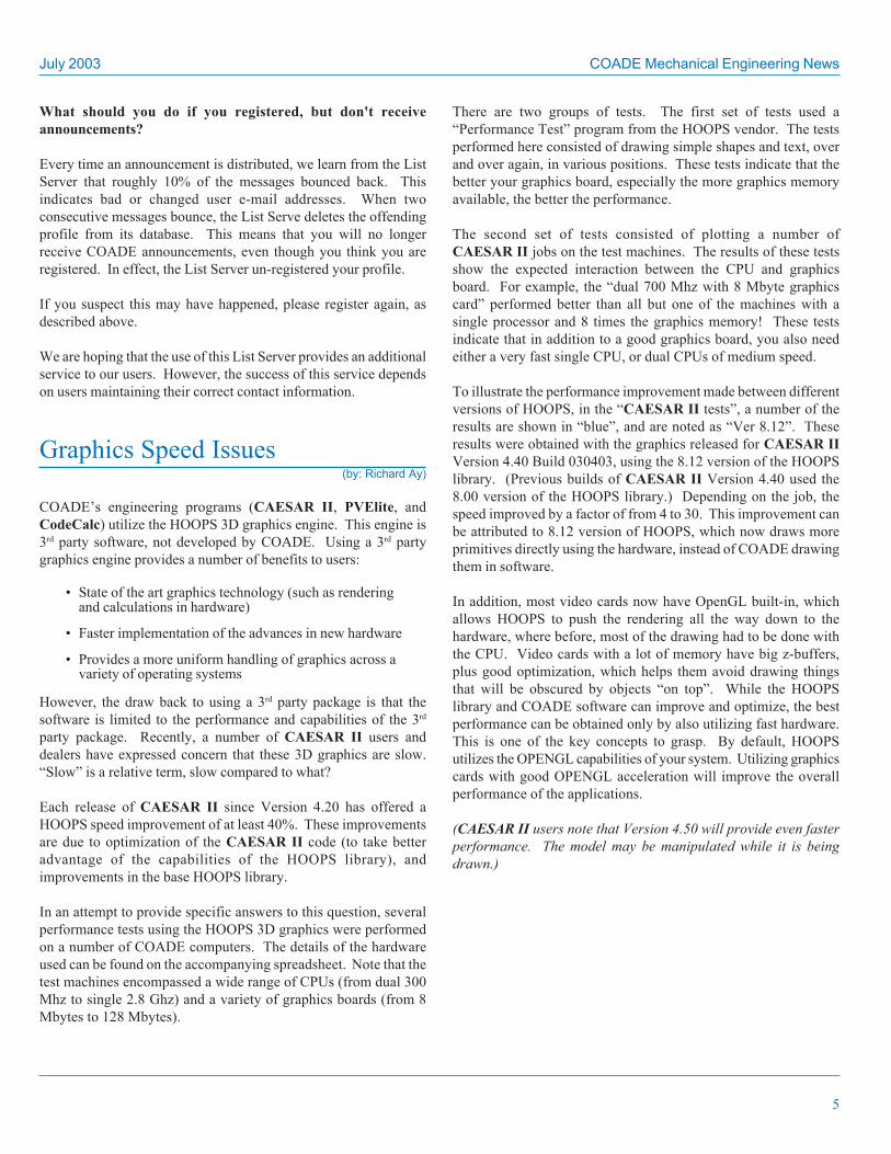
The problem was finally traced, again, to Norton Anti-Virus. NAVinserts a key in the System Registry that forces MS WORD to askpermission before starting. NAV denies permission to allapplications except Internet Explorer. (This is not good becausethis registry key is buried beneath a Microsoft Word key, in a part ofthe registry users should not really be adjusting.) However, thesolution is to remove this key and contact Norton.
Unfortunately, this isn’t a permanent solution because NAV willre-insert the key, on some machines everytime it reboots. Eventhough some versions of NAV have an “enable Word Automation”option, it doesn’t correct this problem with the registry. Someversions of NAV insert this key and provide NO “enable WordAutomation” switch. Uninstalling NAV does not remove this keyfrom the registry! Norton says they are working on the problem –see the information in the figure below, from Norton’s web site.
For those who want to edit their registry and remove this key,perform these steps.
1. Click the Start|Run menu, then type REGEDIT in the “Run”dialog box.
2. Expand the HKEY_CLASSES_ROOT\CLSID key.
3. Scroll down the list until you see {00020906-0000-0000-C000-000000000046} and expand it. There are several keysthat look alike, or differ by only one number, so make surethat the one you choose matches exactly. This is the “secretcode” used by Microsoft to determine when and how Windowswill start MSWord.
4. Under this key will be an entry named “InProcServer32”.Right-click it and select “Delete”. The value that is storedhere points to a Norton file named “Symantec Shared/ScriptBlocking/scrblock.dll”. This part of the registry should looklike the figure below.
COADE Mechanical Engineering News July 2003
8
5. Close REGEDIT.
6. CAESAR II should be able to invoke MSWord now, at leastuntil NAV modifies the registry again.
If modifying the registry isn't an option, the only solution we areaware of is to remove NAV from the machine.
Users who continue to have problems exporting data to MS WORD,and have had NAV installed at anytime on their machine, shouldcontact Norton directly.
CAESAR II Version 4.50(by: Richard Ay)
CAESAR II Version 4.50 will likely be in “Beta Testing” by thetime you read this. In addition to piping code revisions, some of theother enhancements for this release include:
• Revised material database for B31.1 A2002 changes
• “Load Case Template” implemented for recommending staticload cases.
• Reducer element added.
• Major graphics improvements, including:
• A walk-through option is available.
• The static output processor can now producecolored stress plots of the piping system.
• A graphical find (zoom to) option has been added.
• Model drawing during CPU idle time.
• The static output processor remembers all user settings (filters,labels, and report size).
• New dynamic (HTML) help system for piping input andconfiguration.
• Automatic acquisition of website software updates.
• Combined WRC-107/297 module for local stress calculations
• The structural steel interface has been redesigned for easieroperation.
• Spectrum generation wizard

July 2003 COADE Mechanical Engineering News
9
Integration of Tubesheet andExpansion Joint Analysis
(by: Mandeep Singh)
In previous versions of CodeCalc, the fixed tubesheet and the thickExpansion Joint (flanged and flued) modules were not integrated. Ifthe exchanger design required a thick expansion joint, a manualtransfer of some information (spring rates and prime pressures)between the tubesheet results and the expansion joint input musthave been made. In version 6.50 these two modules have beenintegrated. Hopefully this automation reduces the design time ofthese elements and reduces transcription errors.
In this version, when multiple fixed tubesheet load cases areanalyzed, the corresponding expansion joint cases are automaticallyrun. A summary of results is provided at the end of the report. Asingle execution of the TEMA tubesheet module can accomplishwhat required many different runs and manual data transfer betweenmodules, in the previous version.
Discussion of the New Input
On the Shell tab the design code can be selected from the drop downbox. The British code (PD 5500) is available in conjunction withthe TEMA code. This allows the program to customize the input perthe appropriate code selected.
Shell tab:
Tubes tab:
Input on the tubes tab was reorganized for consistency. Check thebox “Tube to Tubesheet Joint information”, to enter informationabout the Tube-Tubesheet joint. CodeCalc will use this informationto check tube to tubesheet welds, and in the case of fixed tubesheets,compute the allowable tube to tubesheet joint load.
Option to specify design code
Using the Tube joint type and the “tested” check box, program automatically puts in the “fr” joint factor.

COADE Mechanical Engineering News July 2003
10
Tubesheet Tab:
This button merges the flange, gasket and bolting input from anexisting flange, into this tubesheet input.
Expansion Joint Tab:
The above screen becomes active only in the case of fixed tubesheetexchangers. The expansion joint can be either a thin (bellows type)or thick (flanged/flued type) or there can be no joint at all.
For a thin expansion joint, only the axial spring rate needs to bespecified.
For a thick expansion joint, either the spring rate needs to bespecified (Design option set to ‘Existing’) or analyze the expansionjoint geometry and allow CodeCalc to compute the spring rate andexpansion joint stresses (Design option set to ‘Analyze’).
This button sets default expansion joint dimensions, based on the shell thickness and material
Procedure for analyzing a Fixed Tubesheet with a ThickExpansion Joint:
Typically in the first pass a fixed tubesheet is analyzed without anexpansion joint. If the configuration (tubes, shell or tubesheet) doesnot pass, and if the cause of the failure is due to differential thermalexpansion, a thick or thin expansion joint can be added. If a thick(flanged and flued) expansion joint is selected, CodeCalc followsthese steps:
1. The axial spring rate of the expansion joint is computed inboth the corroded and new conditions.
2. The expansion joint spring rate is used to compute equivalentdifferential pressure.
3. Next the program extracts the prime pressures (P’s, P’t, Pd)from the output of the tubesheet calculation and uses thosevalues to compute the expansion joint stresses.
4. If multiple tubesheet load cases are selected, a correspondingexpansion joint analysis is automatically performed.
Results of all the runs are summarized in tabular format like the onebelow:
Fixed Tubesheet Required Thickness per TEMA 8th Edition:
Reqd. Thk. + CA —— P r e s s u r e s Case Pass/Case# Tbsht Extnsn Pt’ Ps’ PDif Type Fail———————————————————————————————————————————————————————————————————————1uc 1.471 0.000 71.07 0.00 0.00 Fvs+Pt-Th-Ca Ok2uc 0.750 0.000 0.00 2.39 0.00 Ps+Fvt-Th-Ca Ok3uc 1.471 0.000 71.07 2.74 0.00 Ps+Pt-Th-Ca Ok4uc 0.757 0.000 0.00 0.00 -37.66 Fvs+Fvt+Th-Ca Ok5uc 1.471 0.000 71.04 0.00 -39.07 Fvs+Pt+Th-Ca Ok6uc 0.784 0.000 0.00 2.65 -37.75 Ps+Fvt+Th-Ca Ok7uc 1.471 0.000 71.04 2.74 -39.07 Ps+Pt+Th-Ca Ok8uc 0.750 0.000 0.00 0.00 0.00 Fvs+Fvt-Th-Ca Ok1c 1.491 0.000 70.45 0.00 0.00 Fvs+Pt-Th+Ca Ok2c 0.775 0.000 0.00 2.25 0.00 Ps+Fvt-Th+Ca Ok3c 1.491 0.000 70.45 2.64 0.00 Ps+Pt-Th+Ca Ok4c 0.839 0.000 0.00 0.00 -43.40 Fvs+Fvt+Th+Ca Ok5c 1.490 0.000 70.42 0.00 -45.02 Fvs+Pt+Th+Ca Ok6c 0.863 0.000 0.00 2.55 -43.50 Ps+Fvt+Th+Ca Ok7c 1.490 0.000 70.42 2.63 -45.02 Ps+Pt+Th+Ca Ok8c 0.775 0.000 0.00 0.00 0.00 Fvs+Fvt-Th+Ca Ok——————————————————————————————————————————————————————————————————————Max: 1.491 0.000 in.Given Tubesheet Thickness: 2.0000 in.
Note:Fvt,Fvs - User-defined Shell-side and Tube-side vacuum pressures or0.0.Ps, Pt - Shell-side and Tube-side Design Pressures.Th - With or Without Thermal Expansion.Ca - With or Without Corrosion Allowance.
This button merges the flange, gasket and bolting input from an existing flange, into this tubesheet.
July 2003 COADE Mechanical Engineering News
11
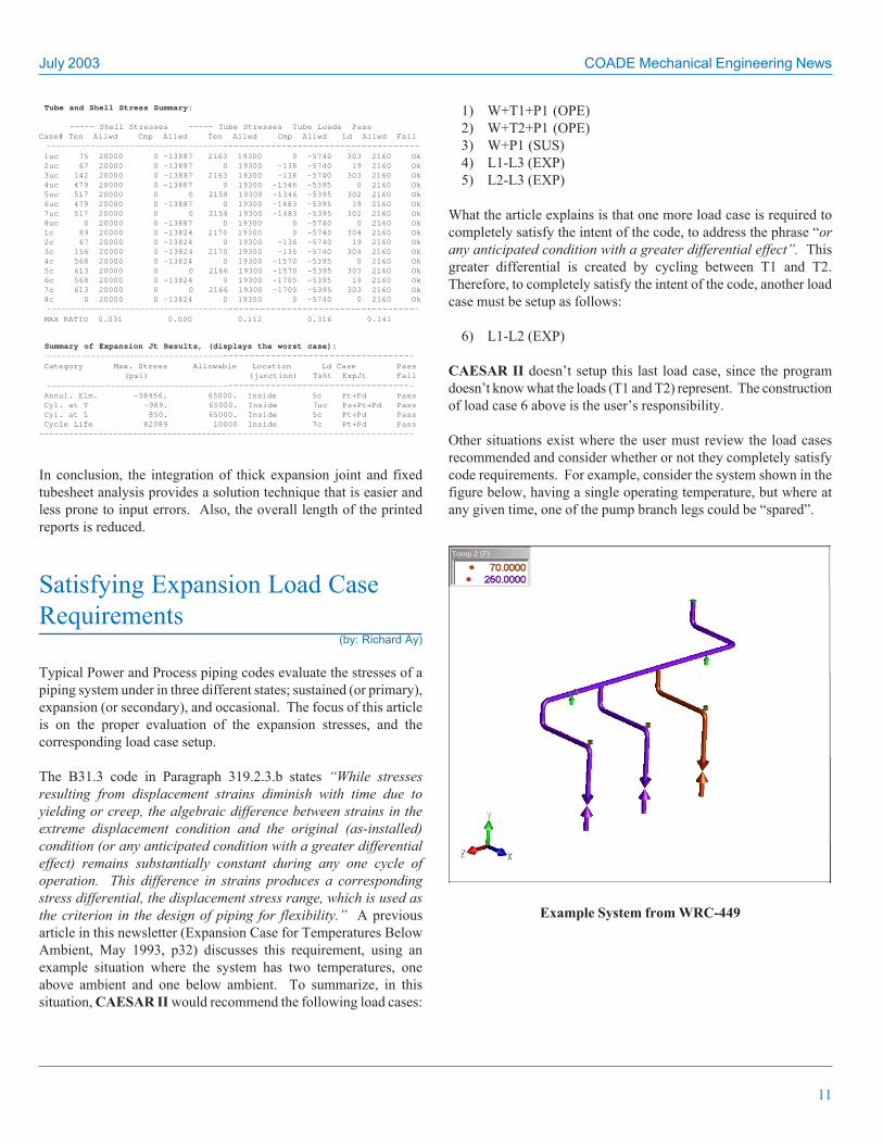
Tube and Shell Stress Summary:
————— Shell Stresses ————— Tube Stresses Tube Loads PassCase# Ten Allwd Cmp Allwd Ten Allwd Cmp Allwd Ld Allwd Fail ————————————————————————————————————————————————————————————————————————— 1uc 75 20000 0 -13887 2163 19300 0 -5740 303 2160 Ok 2uc 67 20000 0 -13887 0 19300 -138 -5740 19 2160 Ok 3uc 142 20000 0 -13887 2163 19300 -138 -5740 303 2160 Ok 4uc 479 20000 0 -13887 0 19300 -1346 -5395 0 2160 Ok 5uc 517 20000 0 0 2158 19300 -1346 -5395 302 2160 Ok 6uc 479 20000 0 -13887 0 19300 -1483 -5395 19 2160 Ok 7uc 517 20000 0 0 2158 19300 -1483 -5395 302 2160 Ok 8uc 0 20000 0 -13887 0 19300 0 -5740 0 2160 Ok 1c 89 20000 0 -13824 2170 19300 0 -5740 304 2160 Ok 2c 67 20000 0 -13824 0 19300 -136 -5740 19 2160 Ok 3c 156 20000 0 -13824 2170 19300 -135 -5740 304 2160 Ok 4c 568 20000 0 -13824 0 19300 -1570 -5395 0 2160 Ok 5c 613 20000 0 0 2166 19300 -1570 -5395 303 2160 Ok 6c 568 20000 0 -13824 0 19300 -1705 -5395 19 2160 Ok 7c 613 20000 0 0 2166 19300 -1705 -5395 303 2160 Ok 8c 0 20000 0 -13824 0 19300 0 -5740 0 2160 Ok ————————————————————————————————————————————————————————————————————————— MAX RATIO 0.031 0.000 0.112 0.316 0.141
Summary of Expansion Jt Results, (displays the worst case): ———————————————————————————————————————————————————————————————————————— Category Max. Stress Allowable Location Ld Case Pass (psi) (junction) Tsht ExpJt Fail ———————————————————————————————————————————————————————————————————————— Annul. Elm. -38456. 65000. Inside 5c Pt+Pd Pass Cyl. at Y -989. 65000. Inside 7uc Ps+Pt+Pd Pass Cyl. at L 850. 65000. Inside 5c Pt+Pd Pass Cycle Life 82089 10000 Inside 7c Pt+Pd Pass—————————————————————————————————————————————————————————————————————————
In conclusion, the integration of thick expansion joint and fixedtubesheet analysis provides a solution technique that is easier andless prone to input errors. Also, the overall length of the printedreports is reduced.
Satisfying Expansion Load CaseRequirements
(by: Richard Ay)
Typical Power and Process piping codes evaluate the stresses of apiping system under in three different states; sustained (or primary),expansion (or secondary), and occasional. The focus of this articleis on the proper evaluation of the expansion stresses, and thecorresponding load case setup.
The B31.3 code in Paragraph 319.2.3.b states “While stressesresulting from displacement strains diminish with time due toyielding or creep, the algebraic difference between strains in theextreme displacement condition and the original (as-installed)condition (or any anticipated condition with a greater differentialeffect) remains substantially constant during any one cycle ofoperation. This difference in strains produces a correspondingstress differential, the displacement stress range, which is used asthe criterion in the design of piping for flexibility.” A previousarticle in this newsletter (Expansion Case for Temperatures BelowAmbient, May 1993, p32) discusses this requirement, using anexample situation where the system has two temperatures, oneabove ambient and one below ambient. To summarize, in thissituation, CAESAR II would recommend the following load cases:
1) W+T1+P1 (OPE)2) W+T2+P1 (OPE)3) W+P1 (SUS)4) L1-L3 (EXP)5) L2-L3 (EXP)
What the article explains is that one more load case is required tocompletely satisfy the intent of the code, to address the phrase “orany anticipated condition with a greater differential effect”. Thisgreater differential is created by cycling between T1 and T2.Therefore, to completely satisfy the intent of the code, another loadcase must be setup as follows:
6) L1-L2 (EXP)
CAESAR II doesn’t setup this last load case, since the programdoesn’t know what the loads (T1 and T2) represent. The constructionof load case 6 above is the user’s responsibility.
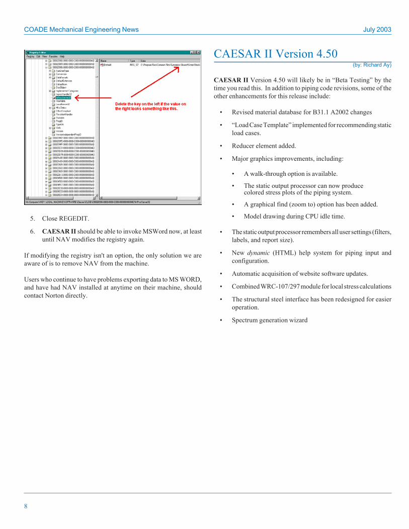
Other situations exist where the user must review the load casesrecommended and consider whether or not they completely satisfycode requirements. For example, consider the system shown in thefigure below, having a single operating temperature, but where atany given time, one of the pump branch legs could be “spared”.
Example System from WRC-449

COADE Mechanical Engineering News July 2003
12
To analyze this system, the following temperature vectors could bedefined.
• “T1” vector – entire system at operating temperature to designhangers
• “T2” vector – entire system at operating temperature exceptleg 1 at ambient
• “T3” vector – entire system at operating temperature exceptleg 2 at ambient
• “T4” vector – entire system at operating temperature exceptleg 3 at ambient
This situation is different than the one discussed in the previousnewsletter article. There is only one operating temperature.However, to satisfy the intent of the code (the extreme displacementstress range), what are the necessary load cases?
CAESAR II will recommend the following set of load cases:
1) W (HGR) restrained weight case forhanger design
2) W+D1+T1+P1 (HGR) hot case for hanger design
3) W+D1+T1+P1+H (OPE) OPE case A with all legs hot
4) W+D2+T2+P1+H (OPE) OPE case B with leg 1 spared
5) W+D3+T3+P1+H (OPE) OPE case C with leg 2 spared
6) W+D4+T4+P1+H (OPE) OPE case D with leg 3 spared
7) W+P1+H (SUS) Sustained (ambient) case
8) L3-L7 (EXP) OPE case A minus Sustained
9) L4-L7 (EXP) OPE case B minus Sustained
10) L5-L7 (EXP) OPE case C minus Sustained
11) L6-L7 (EXP) OPE case D minus Sustained
Are these cases sufficient?
The answer is “no”, they are not sufficient. The system could cyclebetween OPE case B and OPE case C, or between OPE case B andOPE case D, or between OPE case C and OPE case D. So tocompletely satisfy the intent of the code, the following additionalload cases must be setup.
12) L3-L4 (EXP) OPE case A minus OPE case B
13) L3-L5 (EXP) OPE case A minus OPE case C
14) L3-L6 (EXP) OPE case A minus OPE case D
15) L4-L5 (EXP) OPE case B minus OPE case C
16) L4-L6 (EXP) OPE case B minus OPE case D
17) L5-L6 (EXP) OPE case C minus OPE case D
These six additional cases consider the effects of the system cyclingbetween the different possible operating states. This cycling cancause the “extreme” displacement range the code requires.CAESAR II has no knowledge of what OPE cases 3, 4, 5, and 6represent, therefore the program is unable (at the present time) toinclude cases 12 through 17 when it performs its recommendations.These additional load cases are the responsibility of the user.
According to the code, the expansion stress range SE is the largestcomputed displacement stress range. However, SE could comefrom different load combinations, which is a point many analystsmiss. For example, consider the metering station shown in thefigure below.
Metering Station
Either leg could be hot, with the other leg cold. The greatest stresson the tees occurs when switching from one leg to the other. Thedifference between these two operating conditions will produce the“extreme” condition for the proper stress evaluation of the tees.
Understanding the requirements of the applied piping code, as wellas what the recommended load cases represent, is necessary indetermining if the intent of the code is completely satisfied, or ifadditional load cases are necessary.
July 2003 COADE Mechanical Engineering News
13
Mass Spacing for Dynamic Analysis(by: Richard Ay)
Many times when constructing a model for static analysis inCAESAR II, node points are defined only when data changes.Examples of this are: pipe property changes, load changes, geometrychanges, and boundary conditions. In most instances, this nodallayout is sufficient for a static analysis. However, if it is necessaryto evaluate the system for dynamic response, the typical nodallayout for a static analysis may be insufficient. This is because in adynamic analysis of a piping system, the mass is lumped at the nodepoints. Insufficient nodal spacing causes insufficient mass lumping,leading to inaccuracies in the dynamic solution.
Many codes, standards, and technical papers provide similarequations and guidelines for determining the maximum nodal spacingfor dynamic analysis. What is the origin of these equations, andhow can they be applied to piping systems?
The basis for the maximum nodal (mass) spacing is founded on theEuler beam equation. Assuming a simply supported beam, theEuler beam equation relates the circular frequency of harmonicmotion (ω ) to the length of the beam (l), its flexural rigidity (EI),and its mass per unit length (w/g). The mass per unit length (w/g)should include the contribution from the pipe, the fluid contents,and any insulation if applicable.
w
EIgl
nn *)(
2
2πω =
The term (nπ )2 is valid for simply supported beams only, where (n)is the mode of vibration. This equation can be easily rearranged tosolve for the length (l), which will correspond to a specifiedfrequency. Substituting ω = 2π f, the equation used to determinethe span length corresponding to frequency (f in Hz) is:
w
EIgnl *f2)( 2
2
ππ
=
How do we use this? The vibrating wave in a pipeline can beapproximated as the vibration of a simply supported pipe (beam).Therefore this equation can be used to calculate the distance betweennodes (points of no movement) in the vibrating wave (this is the halfwavelength).
Setting (n) to 1 (indicating the first mode of vibration) and setting(f) to the cutoff frequency (for the eigen extraction) yields theminimum wavelength of interest. (This is an important point, whichindicates that the minimum wavelength depends on the type ofdynamic analysis being performed.)
Now that we have the minimum wavelength of interest in the model,idea is to provide sufficient mass points along this span to adequatelymodel this mode (frequency). This can be accomplished byintroducing a constant into the above equation, resulting in:
wEIgnkl *
f2)(*
222
ππ
=
This equation therefore yields the maximum recommended distancebetween the mass points. How does one determine the constant“k”? Work has been done that shows when 3 intermediate masspoints are used along the span, an accuracy of 99.7% is achieved forthe first mode of vibration (of the span). When 2 intermediate masspoints are used, an accuracy of 99% is achieved. (Of course, allfrequencies below the cut-off frequency will be even more accuratelymodeled.) Relating the number of mass points to the constant “k”means that for 3 mass points the span is broken into fourths, thus“k” is ¼. Similarly, for two mass points the span is broken intothirds, thus “k” is 1/3. Therefore the value of (k) is chosen basedupon the accuracy desired.
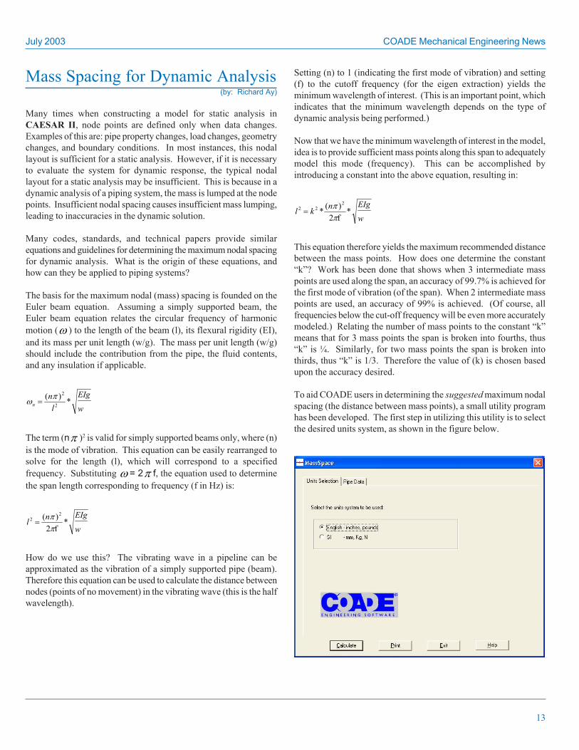
To aid COADE users in determining the suggested maximum nodalspacing (the distance between mass points), a small utility programhas been developed. The first step in utilizing this utility is to selectthe desired units system, as shown in the figure below.

COADE Mechanical Engineering News July 2003
14
Once this selection has been made, the “Pipe Data” tab can bepresented. Filling in the necessary data and clicking on the[Calculate] button yields the maximum suggested nodal spacing, asshown in the figure below.
This utility program can be acquired from the CAESAR II downloadarea of the COADE web site. This program can be used to checkthe maximum nodal spacing of models before running dynamicanalysis.
Assessing the Metal Loss Flawsusing API RecommendedPractice 579
(by: Kevin Kang)
Corrosion and groove-like flaws are common problems that areexperienced by vessels in service. Loss of metal through the vesselwall thickness reduces the strength of the component. At somelocalized points, these flaws may reduce the vessel wall thicknessbelow a minimum Code requirement. Rather than replace the vesselwith a new one, the integrity of the vessel may be checked todetermine its remaining life and whether it can continue to operateat some specified conditions.
API document Recommended Practice 579 can be used to evaluatethe integrity and operational safety of process plant equipment,such as pressure vessels, piping and storage tanks. The results ofthe assessment procedure will provide an estimate for the strengthand the remaining life of the equipment.
Typical approaches for FFS (Fitness For Service) as indicated inAPI 579 are as follows:
• Identifying the Flaw and Damage Mechanism.
• Reviewing the Applicability and Limitations of the FFSAssessment Procedures.
• Gathering data.
• Applying the assessment techniques and comparing the resultto the acceptance criteria.
• Estimating the remaining life for the inspection interval.
• Applying remediation as appropriate.
• Applying in-service monitoring as appropriate.
• Documenting the results
Common degradation mechanisms include general corrosion,localized corrosion, pitting corrosion, blister, mechanical distortionetc. The procedures on how to assess these common flaws arediscussed in the sections described in the Table of Contents of theAPI 579 document.
• Section 1 – Introduction
• Section 2 – Fitness-For-Service Engineering AssessmentProcedure
• Section 3 – Assessment of Equipment for Brittle Fracture
• Section 4 – Assessment of General Metal Loss
• Section 5 – Assessment of Local Metal Loss
• Section 6 – Assessment of Pitting Corrosion
• Section 7 – Assessment of Blisters and Laminations
• Section 8 – Assessment of Weld Misalignment and ShellDistortions
• Section 9 – Assessment of Crack-Like Flaws
• Section 10 – Assessment of Component Operating in theCreep Regimes
• Section 11 – Assessment of Fire Damage
The recently released PVElite 5.0 and CodeCalc 6.5 programshave included metal loss assessments according to API 579 Section4 and Section 5 for vessel elements such as cylindrical shells,simple cones and formed heads. The analysis can be performedusing the Shell and Head Module as depicted in Figure 1 below.

July 2003 COADE Mechanical Engineering News
15
Figure 1. API 579 Analysis Selection
The assessment type either using Section 4 or Section 5 can beselected from the API 579(FFS) tab, as shown in Figure 2.
Figure 2. General and Local Metal Loss Selection
Section 4 covers FFS assessment procedures for components subjectto general metal loss resulting from corrosion and/or erosion. Section5, on the other hand, is a method for analyzing local metal loss orLocal Thin Areas (LTAs) that include groove-like flaws or gouges.In general, flaw assessment using Section 4 provides conservativeresults.
The differences between Section 4 and 5 when applied to LTAs areas follows:
• Section 4: rules for all Level 1 and 2 assessments are based onaverage thickness averaging approach in which is used withCode rules to determine acceptability for continued operation.
• Section 5: rules for Level 1 and Level 2 assessments are basedon establishing a Remaining Strength Factor (RSF) in whichis used to determine acceptability for continued operation.
The Assessment of General Metal Loss described in Section 4 canbe performed using either point thickness (random type readings) orprofile thickness (grid type readings) measurement data. Theselection of the data type readings can be made in the DataMeasurement tab as shown in Figure 3a. The API RecommendedPractice 579 requires a minimum of 15 measurement data. CodeCalccan accommodate up to 99 points.
Figure 3a. Data Measurement Type Selection

COADE Mechanical Engineering News July 2003
16
The localized metal loss assessment described in Section 5, however,can only be performed using profile thickness data. The data matrixcan be set up by providing the number of points in bothcircumferential and longitudinal directions. The matrix size in thiscase is limited to maximum 9x9.
For convenience, Critical Thickness Profile (CTP) data entry is alsoprovided.
The measurement data grid dialog is pictured below in Figure 3b.
Figure 3b. Profile Thickness Data Grid
For most evaluations, it is recommended to first perform theassessment using Section 4, then move on using Section 5 ifnecessary. The rules in Section 4 have been structured to provideconsistent results with Section 5. However, it is the engineer’sresponsibility to review the Assessment Applicability and Limitationwhenever the assessment is changed.
When the acceptance criteria either passes or fails, a respectiveremaining life using a thickness approach or a de-rated value of theMAWP of the vessel will be calculated automatically.
There are three (3) levels of evaluations available for each flaw typedescribed in general as follows:
• Level 1 - typically involving a simplified method usingcharts, simple formulae, and conservativeassumptions.
• Level 2 - generally requires more detailed evaluation andproduces more accurate results
• Level 3 - allows flaw assessment using more sophisticatedmethods such as FEA.
API 579 Section 4 limitations for Level 1 and Level 2 assessmentsare as follows:
• Original design in accordance with a recognized code orstandard.
• The component is not operating in the creep range.
• The region of metal loss has relatively smooth contourswithout notches.
• The component is not in cyclic service (less than 150 totalcycles).
• The component under evaluation does not contain crack-likeflaws.
• The component under evaluation has a design equation inwhich specifically relates pressure and/or other loads, asapplicable, to a required wall thickness.
• With some exception, the following specific components nothaving equation relating pressure and/or other loads to arequired wall thickness may be evaluated using Level 2:
• Pressure vessel nozzles and piping branch connections
• Cylinder to flat head junctions
• Integral tubesheet connections
• Flanges
• Piping systems
Note: Currently CodeCalc does not support API 579 analysison nozzle, flange, tubesheet, flathead, and piping systemcomponents.
The following limitations on applied loads are satisfied:
• Level 1 assessment: components are subject to internal and/orexternal pressure (negligible supplemental loads).
• Level 2 assessment: components are subject to internal and/orexternal pressure and/or supplemental loads such as weight,wind and earthquake.
Limitations for the API 579 Section 5 Level 1 and Level 2assessments are similar to the limitations for Section 4 above withthe following additions:
• The components cannot be subjected to external pressure, orif the flaw is located in the knuckle region of elliptical head(outside of the 0.8D region), torispherical/toriconical head, orconical transition.
July 2003 COADE Mechanical Engineering News
17
• The material component is considered to have sufficientmaterial toughness.
• Special provisions provided for groove-like flaws such as:
• Groove (no mechanical cold work).
• Gouge (mechanical cold work).
It is important that the user fully understand the scopelimitations on each level of the assessments. Please refer to APIRecommended Practice 579 for more details.
The following is the assessment results of the example problem5.11.1 described in the API Recommended Practice 579 bookanalyzed using PVElite 5.0 or CodeCalc 6.5.
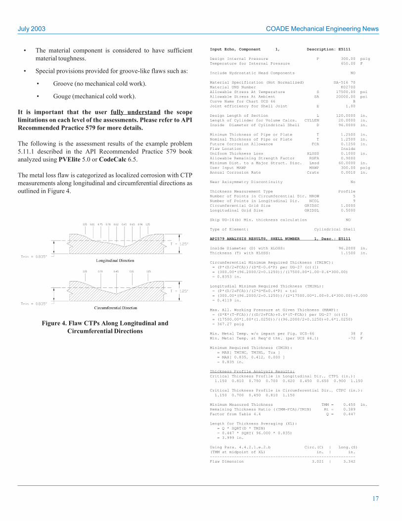
The metal loss flaw is categorized as localized corrosion with CTPmeasurements along longitudinal and circumferential directions asoutlined in Figure 4.
Figure 4. Flaw CTPs Along Longitudinal andCircumferential Directions
Input Echo, Component 1, Description: E5111
Design Internal Pressure P 300.00 psigTemperature for Internal Pressure 650.00 F
Include Hydrostatic Head Components NO
Material Specification (Not Normalized) SA-516 70Material UNS Number K02700Allowable Stress At Temperature S 17500.00 psiAllowable Stress At Ambient SA 20000.00 psiCurve Name for Chart UCS 66 BJoint efficiency for Shell Joint E 1.00
Design Length of Section L 120.0000 in.Length of Cylinder for Volume Calcs. CYLLEN 20.0000 in.Inside Diameter of Cylindrical Shell D 96.0000 in.
Minimum Thickness of Pipe or Plate T 1.2500 in.Nominal Thickness of Pipe or Plate T 1.2500 in.Future Corrosion Allowance FCA 0.1250 in.Flaw Location InsideUniform Thickness Loss XLOSS 0.1000 in.Allowable Remaining Strength Factor RSFA 0.9000Minimum Dist. to a Major Struct. Disc. Lmsd 60.0000 in.User Input MAWP MAWP 300.00 psigAnnual Corrosion Rate Crate 0.0010 in.
Near Axisymmetry Discontinuity No
Thickness Measurement Type ProfileNumber of Points in Circumferential Dir. NROW 5Number of Points in Longitudinal Dir. NCOL 9Circumferential Grid Size GRIDSC 1.0000Longitudinal Grid Size GRIDSL 0.5000
Skip UG-16(b) Min. thickness calculation NO
Type of Element: Cylindrical Shell
API579 ANALYSIS RESULTS, SHELL NUMBER 1, Desc.: E5111
Inside Diameter (D) with XLOSS: 96.2000 in.Thickness (T) with XLOSS: 1.1500 in.
Circumferential Minimum Required Thickness (TMINC): = (P*(D/2+FCA))/(S*E-0.6*P) per UG-27 (c)(1) = (300.00*(96.2000/2+0.1250))/(17500.00*1.00-0.6*300.00) = 0.8353 in.
Longitudial Minimum Required Thickness (TMINL): = (P*(D/2+FCA))/(2*S*E+0.4*P) + tsl = (300.00*(96.2000/2+0.1250))/(2*17500.00*1.00+0.4*300.00)+0.000 = 0.4119 in.
Max. All. Working Pressure at Given Thickness (MAWP): = (S*E*(T-FCA))/((D/2+FCA)+0.6*(T-FCA)) per UG-27 (c)(1) = (17500.00*1.00*(1.0250))/((96.2000/2+0.1250)+0.6*1.0250) = 367.27 psig
Min. Metal Temp. w/o impact per Fig. UCS-66 38 FMin. Metal Temp. at Req’d thk. (per UCS 66.1) -72 F
Minimum Required Thickness (TMIN): = MAX[ TMINC, TMINL, Tca ] = MAX[ 0.835, 0.412, 0.000 ] = 0.835 in.
Thickness Profile Analysis Results:Critical Thickness Profile in Longitudinal Dir., CTPL (in.): 1.150 0.810 0.750 0.700 0.620 0.450 0.650 0.900 1.150
Critical Thickness Profile in Circumferential Dir., CTPC (in.): 1.150 0.700 0.450 0.810 1.150
Minimum Measured Thickness TMM = 0.450 in.Remaining Thickness Ratio ((TMM-FCA)/TMIN) Rt = 0.389Factor from Table 4.4 Q = 0.447
Length for Thickness Averaging (XL): = Q * SQRT(D * TMIN) = 0.447 * SQRT( 96.000 * 0.835) = 3.999 in.
Using Para. 4.4.2.1.e.2.b Circ.(C) | Long.(S)(TMM at midpoint of XL) in. | in.————————————————————————————————————————————————————————————Flaw Dimension 3.021 | 3.342

COADE Mechanical Engineering News July 2003
18
SECTION 5, Local Metal Loss Analysis
Limiting Flaw Size Check: Rt >= 0.20 0.389 >= 0.20 TRUE
(TMM - FCA) >= 0.10 ( 0.450 - 0.125) >= 0.10 0.325 >= 0.10 TRUE
Lmsd >= 1.8 * SQRT(D * TMIN) 60.0000 >= 1.8 * SQRT( 96.000 * 0.835) 60.000 >= 16.119 TRUE
SECTION 5 LEVEL 1 ANALYSIS:
Shell Parameter (LAMDA): = 1.285 * S / SQRT(D * TMIN) = 1.285 * 3.342 / SQRT( 96.000 * 0.835) = 0.480
Longitudinal Check:Figure 5.6 check is ACCEPTABLE with: LAMDA = 0.480 Rt = 0.389
Folias Factor (Mt): = SQRT(1 + 0.48 * LAMDA²) = SQRT(1 + 0.48 * 0.480) = 1.054
Remaining Strength Factor (RSF): = Rt / (1 - 1 / Mt * (1 - Rt)) = 0.389 / (1 - 1 / 1.054 * (1 - 0.389)) = 0.926 >= RSFA ( 0.900 ) Acceptable
Circumferential Check: * Figure 5.7 check is ACCEPTABLE with: C/D = 0.031 Rt = 0.389
SUMMARY SECTION 5 LEVEL 1 ANALYSIS: Calculated Allowable——————————————————————————————————————————————————————————————————Long./Merid. - RSF 0.926 0.900PassedCirc. - Figure 57 CheckPassed
** Section 5 Level 1 Assessment criteria are satisfied **
RLife (Iteration Method) |RSF—>RSFA | : 168.90years
|Rt—>(TMM-(Crate * Time))/TMIN|
SECTION 5 LEVEL 2 ANALYSIS:
Longitudinal Check:Using Slicing Method:With * S = 3.342 in. | Calculated RSFmin: 0.977 * Length Inc.= 0.025 in. | RSFmin > RSFA (0.900)Acceptable
Circumferential Check: * Figure 5.7 check is ACCEPTABLE with: C/D = 0.031 Rt = 0.389
SUMMARY SECTION 5 LEVEL 2 ANALYSIS WITH NO LOAD: Calculated Allowable—————————————————————————————————————————————————————————————————Long./Merid. - RSF 0.977 0.900PassedCirc. - Figure 57 CheckPassed
** Section 5 Level 2 Assessment criteria are satisfied **
CodeCalc 6.5, 2003 ©1989-2003 by COADE Engineering Software
As shown in both the Level 1 and Level 2 summaries of the report,the flaw located on the inside of a vessel does pass Level 1 andLevel 2 assessment criteria. In general, the Level 2 assessment isnot needed when the flaw has passed the Level 1 assessment.However, for checking purposes, both levels of assessment areperformed unless restricted by the scope of limitations.
PC Hardware/Software for theEngineering User (Part 34)
(by: Richard Ay)
Windows XP – “Windows Messenger”
If you don’t use Windows Messenger, you probably want to turn offthe “auto load” of this application. This will save some systemresources, and simply avoid the nuisance of seeing its icon in yourtask bar tray. Here is how to turn this off, for good.
1. Click [Start], then [Run]
2. Type in “gpedit.msc” and press [Enter]. This will start the“Group Policy Editor”.
3. Double click these items to expand them: local computerpolicy, computer configurations, administrative templates,Windows components, Windows Messenger.
4. Now double-click “Do not allow Windows Messenger torun”, then click [Enabled].
5. Click [OK] and then quit the “Group Policy Editor”.
For Windows Messenger Version 4.5 or later, please refer to http://support.microsoft.com/default.aspx?scid=KB;EN-US;q302089&.(Note the semicolons in this link!)
Advanced Searching on the Microsoft (and other) Web Sites
Sooner or later you will have a problem where you need to searchthe “knowledge base” on Microsoft’s web site. This is such a largeweb site, navigation can be difficult. However, the link below isdesigned to bring up a Google search page, that only searchesMicrosoft’s support database. The link is:
h t t p : / / w w w . g o o g l e . c o m / a d v a n c e d _ s e a r c h ? q = + s i t e :support.microsoft.com
Once this search page is displayed, fill in your search criteria, thenclick [Google Search]. This same idea can be extended to any website. For example, to search the COADE web site for any articles ordocuments on friction, this link can be used:
http://www.google.com/advanced_search?q=+site:www.coade.com
Simply change the URL of the website, following the “+site:”qualifier.

July 2003 COADE Mechanical Engineering News
19
Is Spam the Majority of Your E-mail?
Many articles have recently been published concerning the e-mailspam problem. “Spam” is the current hot topic in the press. Someviews even go so far as to claim that spam could render e-mailuseless in the near future if a solution to this problem is not found.
The discussion of one possible solution appeared in the April 2003issue of Network Magazine, in an article titled “Fighting the SpamMonster – and Winning”. The article discussed the various methodsused to fight spam, with particular attention on Bayesian Filtering.Bayesian filtering is an attempt to classify e-mail based on snippetsof text from the e-mail, and a mathematical algorithm to determinethe probability that the message is good, bad, or unsure. Theadvantages and disadvantages of Bayesian filtering are summarizedin the following table.
Advantage Disadvantage
Very effective filtering, over 95% Computationally intensiveof spam caught
Generates few false positives Not well suited forupstream server installation
Automatically learns
Hard for spammers to trick
Allows user fine tuning
Additional details are discussed in the referenced article. So, whatis necessary, how is it setup, how does it work. (The followingdetails are provided for information only. While COADE iscurrently testing the implementation described here, this is notCOADE software. Therefore, COADE can not provide assistanceor support for this anti-spam tool.) The starting point should behttp://spambayes.sourceforge.net, which contains explanations andother necessary links. To summarize, the following steps should beimplemented:
1) Download:spambayes-1.0a2.zip which is the Bayesianfiltering package (available from https://sourceforge.net/p r o j e c t / s h o w f i l e s . p h p ? g r o u p _ i d = 6 1 7 0 2 )
win32all-153.exe, which is a set of Windows extensions forPython (available from http://starship.python.net/crew/m h a m m o n d / w i n 3 2 / D o w n l o a d s . h t m l )
python-2.3a2.exe, which is the Python compiler (availablefrom http://www.python.org/download/)
2) Shut down Outlook for the installation procedure.
3) Install the Python package, then the Win32 extensions, thenthe SpamBayes package.
4) After installation, run “addin.py”, then view about.html.
5) If the installation succeeded, you should see three newcontrols on the Outlook toolbar, as shown in the figure below.
6) Create two new folders in Outlook, the names are irrelevant,but “spam” and “possible-spam” are good choices.
7) Gather as many “spam” e-mails as possible, and move them toyour “spam” folder.
8) Use the “Anti-Spam control to specify all of your folders with“good e-mails”, and your “spam” folder.
9) Then use the “train now” option to initialize and train theBayesian filter.
As new e-mails arrive, they are evaluated. If the filter decides the e-mail is good, it is left in your in-box. If the filter decides the e-mailis spam, it is moved to your “spam” folder. If the filter is unsureabout a particular e-mail, it is moved to the “possible-spam” folder,at which point you can use either the “Delete As Spam” or “Recoverfrom Spam” controls. These controls also enhance the training ofthe filter, so future, similar, e-mails are handled automatically. It isalso recommended that you occasionally re-train the filter, sincespam is continually changing.
Initial use at COADE has shown that 99% of all spam no longerresides in the “in-box”. After a few days of use, virtually all spamgoes to the “spam folder”, with the remainder going to the “possible-spam” folder.
COADE Mechanical Engineering News July 2003
20
CAESAR II NoticesListed below are those errors & omissions in the CAESAR IIprogram that have been identified since the last newsletter. Thesecorrections are available for download from our WEB site, forVersion 4.40.
Static Load Case Setup Module / Dynamic Input
• Corrected the friction multiplier application when static loadcases were deleted on the “edit dialog”.
• Corrected initialization of load case options when changingpiping codes.
• Corrected the storage of wind topographical data for windvectors 2 through 4. This also affects wave data.
Large Job Printing Module
• Modified to handle correction for spring hanger load variationcalculation when “cold load design” is activated.
Material Database Editor
• Corrected the identification of the piping code when addingmaterials to the data base for codes listed after B31.11.
Material Database
• Corrected allowables for B31.3 A312 TP347H over 1000degF.
Low Level Graphics DLL
• Corrected a problem on Win98 with “critical code section”that caused module linked to this DLL to crash on exit.
PipePlus Interface
• Corrected acquisition of bend data in Pipeplus interface.
• Corrected units translation for densities in Pipeplus interface.
• Corrected testing for material and allowable specifications.
• Corrected restraint processing for multiple restraints at thesame node point.
Structural Modeler
• Corrected so that the interface won’t “eat” trailing zeros onexponential notation, i.e. “1e10”.
Configuration Module
• Corrected a “version identification” problem which preventedthe “stress color range settings” from being read from existingconfiguration files.
• Added B31.11 as an option for the “default piping code”.
Buried Pipe Module
• Modified to address new B31.1 materials
• Corrected the element data space initialization.
Dynamic Output Module
• Corrected the input echo of configuration data for:
• translational stiffness units labels
• B31.3_SUS_SIF_FACTOR display
• OCCASIONAL_LOAD_FACTOR display
• Corrected an instance of pathname allocation being too short.
• Corrected the access of nozzle data for input echos.
Animation Module
• Corrected an instance of pathname allocation being too short.
Element Generator
• Corrected an error in generating element loads when “uniformloads” are in G’s, and “W” (weight), “WNC” (weight nocontents), or “WW” (water weight) are not present in the loadcase.
• Changed to include buoyancy effects in load cases based on“WW” (weight with water).
Static Solver
• Corrected the stiffness used for designed constant effortsupports when changing “hanger status” to a setting other than“as designed”.
• Corrected the friction loads when the new “friction mulitplier”was set to zero in the load case setup details.
• Tweaked the friction algorithm for stiffness reset whenconvergence problems occur.
• Corrected to properly lock “predefined spring hangers” forthe hydrotest load case.
July 2003 COADE Mechanical Engineering News
21
Intergraph Interface
• Updated the splitting of bend elements to address both teesand dummy legs.
Miscellaneous Computation Processor
• Modified to address new B31.1 materials
• Corrected “imposed limits” on the crotch radius for B31.8extruded welding tees.
• Corrected the operation of the “spinner control” on the bendSIF dialog so that the number of miter cuts is properlyobtained.
• Corrected the SIFib division by 2 for use in WRC329 EQ 46when SIFob was previously divided by 2.
• Corrected message handler from “eating” the “3” key on thenumeric keypad.
Offshore DLL
• Corrected a “dimensionless parameter” used in the StreamFunction wave theory, which was actually units dependent.
Nozzle Input Echo Format File
• Corrected template for nozzle input echo.
ODBC Export DLL
• Corrected the output of the “Lisega” spring size when sendingdata through the “Data Export Wizard” (ODBC).
• Modified to handle correction for spring hanger load variationcalculation when “cold load design” is activated.
Static Stress Computation Module
• Corrected a material input/output procedure to addresscombined piping files.
• Corrected the usage of “Sh” values for B31.8 Ch VIII,affecting multipe OPE cases.
• Modified the bending term in “3D Max Stress Intensity”calculation for “hydrotest” load cases.
Static Output Module
• Modified all output filters to use a “logical and” instead of a“logical or” when a node number range is specified.
• Added the conversion of the “hydrotest pressure” field to theroutine for input echo display.
• Corrected re-initialization of graphics data space whenswitching jobs from within the output processor.
• Corrected the determination of the data directory path whenswitching jobs from within the output processor.
• Corrected the formatting of node numbers in the “restraintsummary report” for nodes with multiple restraints.
• Corrected the input echo of configuration data for:
• translational stiffness units labels
• B31.3_SUS_SIF_FACTOR display
• OCCASIONAL_LOAD_FACTOR display
• Initialized printer device context flags before getting thedevice defaults.
• Corrected the graphical display of displacement values when“Z axis vertical” is activated.
• Corrected the access of nozzle data for input echos.
• Corrected the printing of stress titles for TD/12 code when the“yield stress criterion” is set to “Von Mises”.
• Corrected the computation of spring hanger load variationwhen “cold load design” is activated.
• Corrected shutdown of program using “File\Exit” when printingis in progress.
Piping Error Check Module
• Corrected the over-ride of the thickness used in the B31.1effective section modulus calculation for SUS and OCC loadcases when the “B31.1 Reduced Z Fix” configuration directivewas activated. This change only affects those tees where the“branch connection” equation is used.
• Modified to address new B31.1 materials
• Corrected “imposed limits” on the crotch radius for B31.8extruded welding tees.
• For B31.3 Welding Tees and Sweepolets, changed the test for“Note 11” to correct a “code” error.
• Corrected table pointers for B31.1/B31.3 “y” parameter usedin minimum wall thickness calculations.
• Corrected the SIFib division by 2 for use in WRC329 EQ 46when SIFob was previously divided by 2.
• Corrected handling/storage of material data for “included”job files.

COADE Mechanical Engineering News July 2003
22
Interfacing DLL
• Corrected handling of temporary material file.
Piping Input Module
• Corrected the activation of the “Eff” field for new jobs whenthe code is switched to B31.8.
• Modified so the “seam weld” setting is assumed for new bendswhen using the TD/12 code.
• Corrected the operation of the “Element LIST” dialog toallow proper editing of the fields following the “hydrotestpressure” field.
• Corrected the input echo of configuration data for:
• translational stiffness units labels
• B31.3_SUS_SIF_FACTOR display
• OCCASIONAL_LOAD_FACTOR display
• Modified to address new B31.1 materials
• Corrected the usage of the “block rotate setup” options.
• Corrected “SaveAs” function to handle .SOI and .XML files.
• Corrected the display of the “count” of “node names” in themodel status auxiliary display.
• Corrected the “UNDO” operation when invoked from theLIST.
• Corrected the access of nozzle data for input echoes.
WRC107 Module
• Corrected the use of the “Z-up” flag.
• Corrected to initialize all graphics variables between differentload cases
TANK NoticesListed below are those errors & omissions in the TANK programthat have been identified since the last newsletter. These correctionsare available for download from our WEB site, for Version 2.40.
1) Solution Module:
• Corrected the reset of minimum shell thickness (6mm)when working in metric units.
• Corrected the use of the “FULL_SHELL_WEIGHT_IN_APP_F” directive in the computations.
2) Output Module:
• Corrected the output of the annular base plate weight.
• Corrected the use of the units conversion constant for“threads per unit length”.
• Corrected the use of the units conversion constant for“nozzle expansion coefficient.
• Corrected the output of two configuration directives for theinput echo.
3) Units Generation Utility:
• Corrected the conversion factor for “rotational stiffness”for “N-m/deg”.
4) Error Check Module:
• Corrected the check of “seismic data” to allow “-1” as validinput for the seismic zone.
CODECALC NoticesListed below are those errors & omissions in the CODECALCprogram that have been identified since the last newsletter.
1) TEMA Tubesheet module:
• Properly corroding the outer cylinder of the Expansion Jt.
• Added warning for the tube pitch.
• Corrections in the Tube-Tubesheet full-strength weld calcs.
• Correctly interpreting the flange load transferred to thetubesheet that are entended but the bolt load is not transferredto them.
• For floating tubesheet, added input for G of the stationarytubesheet.
2) Program Interface:
• Addressed issues relating to switching between input andgraphics views.
• Fixed some dialogs that were closing on hitting Enterkey, instead of tabbing to the next input field.
• Modified the reading of title page data for older files.
• Added some missing materials in the material database.

July 2003 COADE Mechanical Engineering News
23
3) Shell:
• Corrections to API-579, calculation of c value.
• Fixed MAWP on the status bar for jobs with static headspecified.
4) Nozzle:
• Fixed some issues relating to results on the status bar.
5) Flange:
• Corrections to the blind flange calculations.
• Added check for Lap Joint.
PVElite NoticesListed below are those errors & omissions in the PVElite programthat have been identified since the last newsletter.
1) Algebraic force/moment summation for base skirt supportedvessels was corrected.
2) On screen nozzle calcs for external pressure were not consideringthe shell CA. This has been corrected.
3) Changed Nozzle diameter limit and added pad area for 5500closely spaced nozzle check.
4) The “F” factor was being used on offset hillside nozzles incylinders unintentionally for the external tr case.
5) Fixed on screen calc of the pad diameter when the pad widthwas entered on actual thickness basis for larger nozzles.
6) Fixed the on screen weld calc for required thickness of theinside weld.
7) Sorted out a memory issue with the output processor and colorhightlighting.
8) Implemented new computation for partial volumes of non-standard F&D Heads.
9) Sorted out a sign issue for cone/knuckle/ring/shell inertia calc.
10) Fixed the use of local shell thickness for the on screen nozzlecalcs.
11) Some 3D graphics features were fixed, such as nozzle onnozzle plotting.
12) For leg baseplates when there were 0 bolts in tension theprogram could abort.
13) When user defined wind pressure was specified and there was atop head platform, the wind load on the platform may not havebeen calculated in some cases.
14) When user specified axial loads were entered at cone/cylinderjunction, they may not have been consider in the Q calculation.
COADE Releases CADWorx 2004Simultaneously with AUTOCAD®2004, Co-Promotes Products withAUTODESK
(by: John Brinlee)
On March 17, 2003, COADE released CADWorx Version 2004,the latest version of its AutoCAD-based Plant Design Suite. Therelease culminated a development period during which COADEworked closely with Autodesk as one of only four softwaredevelopers worldwide selected to release an AutoCAD 2004-basedproduct on the same day, coincident with the debut of Autodesk’snew release, AutoCAD 2004 (note that CADWorx is also compatiblewith AutoCAD versions 2000, 2000i, and 2002). CADWorx 2004not only offers process industry designers the ability to immediatelytake advantage of the groundbreaking enhancements in AutoCAD2004, but also provides many new features compared to COADE’sprevious version, CADWorx 2002.
By leveraging Autodesk’s investment in the next release ofAutoCAD, COADE’s new version of CADWorx greatly increasesthe size of plant models that teams of designers can work onsimultaneously, while making it much easier to learn and use theprogram. These dramatic improvements in both performance andfunctionality are made possible by significant file size reduction,faster load and save times, enhanced management of externalreferences (XREFs), and user interface refinements such as the newtool palette system.
In addition to offering compatibility with AutoCAD 2004, CADWorx2004 offers many other new features. The CADWorx PIPE 2004module provides improved integrated steel capabilities, integratedHVAC/cable tray components, automatic weld gaps, and layeringby line number. New capabilities in CADWorx P&ID 2004 includeenhanced copy procedures, an auto repeat feature, and a dropdownlist for instant data entry.

COADE Mechanical Engineering News July 2003
24
12777 Jones Rd. Suite 480 Tel: 281-890-4566 Web: www.coade.comHouston, Texas 77070 Fax: 281-890-3301 E-Mail: [email protected]
COADE Engineering Software
Thomas Van Laan, president of COADE, believes that the improvements offered in AutoCAD 2004 are exactly those for which the plantdesign industry has been hoping. Says Van Laan, “Our customers are always concerned with three things - speed, size, and how to managethem - so we think our customers will love this new version of AutoCAD. We’ve found that a 22-megabyte project created under CADWorx2002 drops to less than 6 megabytes under CADWorx 2004, a dramatic 70%+ reduction in project file size.” Van Laan continued,“CADWorx has always taken maximum advantage of AutoCAD’s XREF capabilities to the hilt. The new XREF management features,including improved load speed and change notification, are perfect complements to the way that our customers manage large projects.”
John Sanders, Vice President Platform Technology Division for Autodesk, agrees that COADE has done a great job leveraging the bestfeatures of AutoCAD 2004. Sanders says, “We are very pleased that COADE was able to develop a 2004-compatible version of CADWorxso quickly. Autodesk has been working very closely with COADE to determine what AutoCAD enhancements that would be most valued bythe plant design community. We’re impressed by how they have leveraged the strengths of AutoCAD 2004 - speed, teamwork andmanagement - and translated these strengths into productivity improvements for process plant designers. CADWorx 2004 is a great tool foranyone involved in the design of process plants.”
Following the release, COADE and Autodesk collaborated on a multi-city tour to conclusively demonstrate the advantages of CADWorx2004 operating in an AutoCAD 2004 environment. Presentations showing how CADWorx 2004 can offer a more economic plant designsolution over a full range of project sizes were made to receptive audiences in Houston, New Orleans, Philadelphia, New York, Boston,Chicago, Calgary, Singapore, Antwerp, and Moscow with more of the same touted for Birmingham, Atlanta, Seattle and Kuala Lumpur inmid to late July.
CADWorx 2004 Takes Advantage of Gates Barman of Hanover CorporationAutoCAD 2004's Finest Features Receives the First Copy of CADWorx 2004