mechanical engineering final - tvetreform.org.pk material... · mechanical engineering mr. sajid...
TRANSCRIPT

Mechanical Engineering
Mr. Sajid Ali

(c) TVET Reform Support Programme, 2014
All copying, reprint, or storage in electronic media – including extracts - require the written permission of the management of the TVET Reform Support Programme. The author of this text is responsible for its technical correctness.

3
Table of Content
Literature .................................................................................................................................. 5
1 Introduction to Machine Drawing ............................................................................ 7
Learning Objectives ................................................................................................................................. 7
Preface ........................................................................................................................................................ 7
1.1 Introduction to Drawing ................................................................................................................. 7
1.2 Introduction to Machine Drawing ................................................................................................ 7 1.2.1 Importance Of Graphic Language ....................................................................................... 8 1.2.2 Classification of Drawing ..................................................................................................... 9
1.3 Machine drawing ............................................................................................................................. 9
1.4 Production Drawing ...................................................................................................................... 10
1.5 Part Drawing ................................................................................................................................... 10
1.6 Assembly Drawing ........................................................................................................................ 10
1.7 Design Assembly Drawing .......................................................................................................... 10
1.8 Detailed assembly drawing ......................................................................................................... 11
1.9 Sub- Assembly Drawing .............................................................................................................. 11
1.10 Installation Assembly Drawing .................................................................................................. 11
1.11 Assembly Drawings for catalogues ............................................................................................ 12
1.12 Assembly drawing for instruction manuals ............................................................................. 12
1.13 Exploded Assembly Drawing ...................................................................................................... 13
1.14 Machine shop drawing ................................................................................................................. 14 Activity 1 .......................................................................................................................................... 14 1.14.1 Pipe layout ............................................................................................................................ 15 Activity 2 .......................................................................................................................................... 15
Task 1 ........................................................................................................................................................ 15
2 Simple Stresses in Machine Parts ............................................................................ 17
Learning Objectives ............................................................................................................................... 17
Preface ...................................................................................................................................................... 17
2.1 Simple Stresses in Machine Parts ............................................................................................... 17
2.2 Stress strain diagram ..................................................................................................................... 18
Activity 3 .................................................................................................................................................. 21
Task 2 ........................................................................................................................................................ 21
3 Hand Processes ............................................................................................................ 23
Learning Objectives ............................................................................................................................... 23
Preface ...................................................................................................................................................... 23
3.1 Introduction .................................................................................................................................... 23
3.2 Hand Processes ............................................................................................................................... 24

4
3.2.1 Types of Engineering Files .................................................................................................. 24 3.2.2 Filing ...................................................................................................................................... 26 Activity 4 .......................................................................................................................................... 26 3.2.3 The Hacksaw ........................................................................................................................ 27 3.2.4 Cold chisels ........................................................................................................................... 29 Activity 5 .......................................................................................................................................... 29 Activity 6 .......................................................................................................................................... 33
Task 3 ........................................................................................................................................................ 33
4 Sheet Metal Operations ............................................................................................. 35
Learning Objectives ............................................................................................................................... 35
Preface ....................................................................................................................................................... 35
4.1 Introduction ..................................................................................................................................... 35
4.2 Sheet Metal Operations ................................................................................................................. 36 4.2.1 Cutting and bending sheet metal ....................................................................................... 36 4.2.2 Development......................................................................................................................... 39 Activity 7 .......................................................................................................................................... 40
Task 4 ........................................................................................................................................................ 40

5
Literature
K.L Narayana, P.Kannaiah, & K, Venkata Reddy (2006): Machine Drawing; 3rd edition , New international Publisher.
NISTE ministry of education Government of Pakistan (2001). Basic Elec-trical Engineering Drawing And Computer Aided Design-I; 1st edition national Book Foundation.
R.S Khurmi, J.K Gupta(2005). A Text Book of Machine Design. Eurasia Publishing House (Pvt.) LTD.
Shingley.(2006). Mechanical Engineering 8th edition, McGraw- Hill
Bruec. J. Black, C.Eng. MIEE (2004). Workshop processes, practices and material. 3rd edition Elsevier.
Rolald. A. Walsh( 2001): Marching and metal working calculation Mc-Graw-Hill
Black, Bruce J. (2004): Workshop processes, practices and material. 3rd edition Elsevier.
Rolald. A.Walsh (2001): Marching and metal working calculation Mc-Graw- Hill


7
1 Introduction to Machine Drawing
Learning Objectives
Upon completion of this unit the learner will be able to:
Describe engineering drawing
Describe Importance of graphic language
Describe need of correct drawing
Describe Classification of Drawing
Describe pipe layout
Preface
Drawing is said to be the “language of industry” and serves many useful pur-poses, so it is very important. Our modern industry could not exist without engineering drawing. In the industry making the drawings firstly plans a pro-duct: selection of materials, manufacturing and processes, routing, heat treat-ment. Tolerance and assembling the parts all depends on drawing. A number of persons are involved to complete this product with the help of drawings. In other word engineer communicate his ideas with the help of engineering draw-ing and everybody understands that.
1.1 Introduction to Drawing
Drawing is a language by which we can narrate our mind ideas on a paper using some drawing instruments or freely. In this chapter we will discuss the types of engineering drawing with practical examples and learnt how to draw different drawing with the help of different tasks & activities.
1.2 Introduction to Machine Drawing
Drawing is a language of lines, symbols, sizes, shapes and space relationships is called drawing. Engineering drawing is a graphic language that express and con-veys ideas of shape, size, and type of material, finish, fabrication, and construc-tion of part or mechanism clearly and concisely to others.
A technical person can use the graphic language as powerful means of communi-cation with others for conveying ideas on technical matters. However, for effec-tive exchange of ideas with others, the engineer must have proficiency in (i) language, both written and oral, (ii) symbols associated with basic sciences and (iii) the graphic language. Engineering drawing is a suitable graphic language from which any trained person can visualize the required object. As an enginee-ring drawing displays the exact picture of an object, it obviously conveys the same ideas to every trained eye.

8
Irrespective of language barriers, the drawings can be effectively used in other countries, in addition to the country where they are prepared. Thus, the en-gineering drawing is the universal language of all engineers. Engineering drawing has its origin sometime in 500 BC in the regime of King Pharos of Egypt when symbols were used to convey the ideas among people
1.2.1 Importance Of Graphic Language
The graphic language had its existence when it became necessary to build new structures and create new machines or the like, in addition to representing the existing ones. In the absence of graphic language, the ideas on technical matters have to be conveyed by speech or writing, both are unreliable and difficult to understand by the shop floor people for manufacturing. This method involves not only lot of time and labour, but also manufacturing errors. Without en-gineering drawing, it would have been impossible to produce objects such as aircrafts, automobiles, locomotives, etc., each requiring thousands of different components.
The drawings prepared by any technical person must be clear, unmistakable in meaning and there should not be any scope for more than one interpretation, or else litigation may arise. In a number of dealings with contracts, the drawing is an official document and the success or failure of a structure depends on the clarity of details provided on the drawing. Thus, the drawings should not give any scope for misinterpretation even by accident. It would not have been possible to produce the machines/automobiles on a mass scale where a number of assemblies and sub-assemblies are involved, without clear, correct and accu-rate drawings.
The study of machine drawing mainly involves learning to sketch machine parts and to make working and assembly drawings. This involves a study of those conventions in drawings that are widely adopted in engineering practice

9
1.2.2 Classification of Drawing
1) Machine drawing 2) Production drawing 3) Part drawing 4) Assembly drawing 5) Design assembly drawing 6) Detailed assembly drawing 7) Sub- assembly drawing 8) Installation assembly drawing 9) Assembly drawing for catalogues 10) Assembly drawings for instruction manuals 11) Exploded assembly drawing 12) Machine shop drawing
1.3 Machine drawing
It is pertaining to machine parts or components. It is presented through a num-ber of orthographic views, so that the size and shape of the component is fully understood. Part drawings and assembly drawings belong to this classification.

10
1.4 Production Drawing
A production drawing, also referred to as working drawing, should furnish all the dimensions, limits and special finishing processes such as heat treatment, honing, lapping, surface finish, etc., to guide the craftsman on the shop floor in producing the component. The title should also mention the material used for the product, number of parts required for the assembled unit, etc.
Since a craftsman will ordinarily make one component at a time, it is advisable to prepare the production drawing of each component on a separate sheet. How-ever, in some cases the drawings of related components may be given on the same sheet
1.5 Part Drawing
Component or part drawing is a detailed drawing of a component to facilitate its manufacture. All the principles of orthographic projection and the technique of graphic representation must be followed to communicate the details in a part drawing. A part drawing with production details is rightly called as production drawing or working drawing
1.6 Assembly Drawing
A drawing that shows the various parts of a machine in their correct working locations is an assembly drawing. There are several types of such drawings.
1.7 Design Assembly Drawing
When a machine is designed, an assembly drawing or a design layout is first drawn to clearly visualize the performance, shape and clearances of various parts comprising the machine.

11
1.8 Detailed assembly drawing
It is usually made for simple machines, comprising of a relatively smaller num-ber of simple parts. All the dimensions and information necessary for the con-struction of such parts and for the assembly of the parts are given directly on the assembly drawing. Separate views of specific parts in enlargements, showing the fitting of parts together, may also be drawn in addition to the regular assembly drawing.
1.9 Sub- Assembly Drawing
Many assemblies such as an automobile, lathe, etc., are assembled with many pre-assembled components as well as individual parts. These pre-assembled units are known as sub-assemblies. A sub-assembly drawing is an assembly drawing of a group of related parts that form a part in a more complicated machine. Examples of such drawings are: lathe tail-stock, diesel engine fuel pump, carburetor, etc.
1.10 Installation Assembly Drawing
On this drawing, the location and dimensions of few important parts and overall dimensions of the assembled unit are indicated. This drawing provides useful information for assembling the machine, as this drawing reveals all parts of a machine in their correct working position

12
1.11 Assembly Drawings for catalogues
Special assembly drawings are prepared for company catalogues. These draw-ings show only the pertinent details and dimensions that would interest the potential buyer.
1.12 Assembly drawing for instruction manuals
These drawings in the form of assembly drawings are to be used when a machine, shipped away in assembled condition, is knocked down in order to check all the parts before reassembly and installation elsewhere. These drawings have each component numbered on the job
13
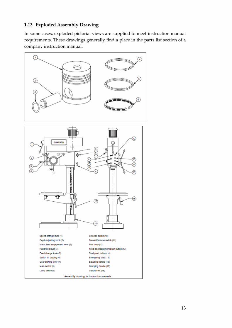
1.13 Exploded Assembly Drawing
In some cases, exploded pictorial views are supplied to meet instruction manual requirements. These drawings generally find a place in the parts list section of a company instruction manual.

14
1.14 Machine shop drawing
Rough castings and forgings are sent to the machine shop for finishing operation. Since the machinist is not interested in the dimensions and information of the previous stages, a machine shop drawing frequently gives only the information necessary for machining. Based on the same principle, one may have forge shop drawing, pattern shop drawing, sheet metal drawing, etc.
Activity 1
Draw machine drawing of given mechanical part on A3 paper
Draw Production drawing of given mechanical part on A3 paper
Instructions
1) Draw a boarder of 15mm from all four sides 2) Make title block on drawing sheet to right bottom corner 3) Use 2H grade pencil to draw. 4) Use separate for each drawing
15
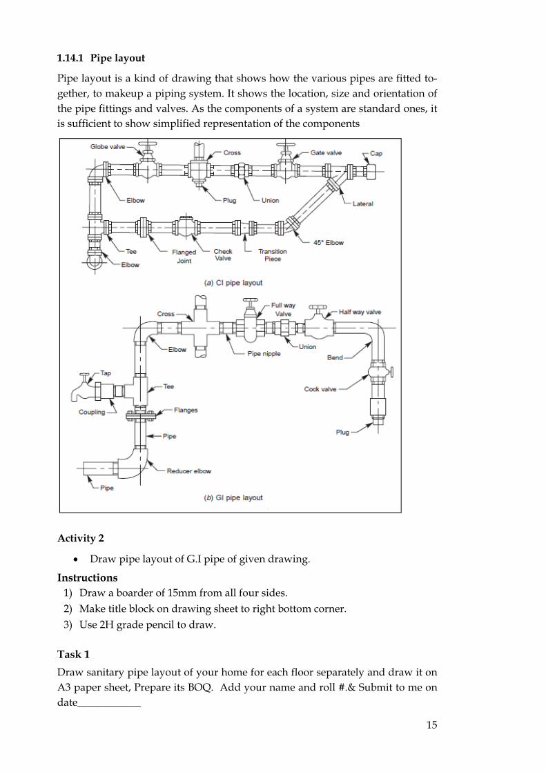
1.14.1 Pipe layout
Pipe layout is a kind of drawing that shows how the various pipes are fitted to-gether, to makeup a piping system. It shows the location, size and orientation of the pipe fittings and valves. As the components of a system are standard ones, it is sufficient to show simplified representation of the components
Activity 2
Draw pipe layout of G.I pipe of given drawing.
Instructions 1) Draw a boarder of 15mm from all four sides. 2) Make title block on drawing sheet to right bottom corner. 3) Use 2H grade pencil to draw.
Task 1
Draw sanitary pipe layout of your home for each floor separately and draw it on A3 paper sheet, Prepare its BOQ. Add your name and roll #.& Submit to me on date____________


17
2 Simple Stresses in Machine Parts
Learning Objectives
Upon completion of this unit the learner will be able to:
Describe load, stress, strain,
Describe young’s modulus of elasticity
Describe stress-strain diagram.
Preface
The simple stresses in machine parts is the study of new &better machines and improving the existing ones using different design formula which we will discuss in this chapter. Anew or better machine is one which is more economical in the overall cost of production and operation.
2.1 Simple Stresses in Machine Parts
In engineering practice, the machine parts are subjected to various forces which may be due to either one or more of the following:
Energy transmitted,
Weight of machine,
Frictional resistances,
Inertia of reciprocating parts,
Change of temperature, and
Lack of balance of moving parts.
The different forces acting on a machine part produces various types of stresses, which will be discussed in this chapter.
I. Load It is defined as any external force acting upon a machine part. The following four types of the load are important.
Dead or steady load: A load is said to be a dead or steady load when it does not change in magnitude of direction
Live or variable load: A load is said to be a live or vriable load when it changes continually
Suddenly applied or shock loads: A load is said to be a suddenly applied or shock load when it is suddenly applied or removed
Impact load: A load is said to be an impact load when it is applied with some initial velocity.

18
2. Stress When some external system of forces or loads act on a body the internal forces are set up at various sections of the body which resist the external forces. This internal force per unit area at any section of the body is known as unit stress of simply stess. It is denoted by a greek letter sigma. Mathematically:
3. Strain When a system of forcs or loads act on a body . it undergoes some deformation . this deformation per uit length is known as unit strain or simply strain. It is denoted by a greek letter epsilon.mathematically:
Young’s Modulus or Modulus of Elasticity:
2.2 Stress strain diagram
In designing various parts of a machine it is necessary to know how the material will function in service. For this certain characteristics or properties of the material should be known. The mechanical properties mostly used in mechanical engineering practice are commonly determined from a standard tensile test. This test consists of gradually loading a standard specimen of a material and noting the corresponding values of load elongation until the specimen fractures.
A stress strain diagram for a mild steel under tensile test is shown and the various properties of the material are discussed below

19
a. Proportional Limit We see from the diagram that from point O to A is a straight line, which represents that the stress is proportional to strain. Beyond point A, the curve slightly de-viates from the straight line. It is thus ob-vious, that Hook’s law holds good up to point A and it is known as proportional limit. It is defined as that stress at which the stress-strain curve begins to deviate from the straight line.
b. Elastic Limit It may be noted that even if the load is increased beyond point A up to the point B, the material will regain its shape and size when the load is removed. This means that the material has elastic pro-perties up to the point B. This point is known as elastic limit. It is defined as the stress developed in the material without any permanent set.
Note: Since the above two limits are very close to each other, therefore, for all practical purposes these are taken to be equal
c. Yield Pont If the material is stressed beyond point B, the plastic stage will reach i.e. on the removal of the load, the material will not be able to recover its original size and shape. A little consideration will show that beyond point B, the strain increases at a faster rate with any increase in the stress until the point C is reached. At this point, the material yields before the load and there is an appreciable strain with-out any increase in stress. In case of mild steel, it will be seen that a small load drops to D, immediately after yielding commences. Hence there are two yield points C and D. The points C and D are called the upper and lower yield points respectively. The stress corresponding to yield point is known as yield point stress.
d. Ultimate Stress At D, the specimen regains some strength and higher values of stresses are re-quired for higher strains, than those A and D. The stress (or load) goes on increa-sing till the point E is reached. The gradual increase in the strain of the specimen is followed with the uniform reduction of its cross sectional area. The work done during stretching the specimen is transformed largely into heat and the specimen become hot. At E the stress which attains its maximum value is known as ultimate stress.

20
e. Breaking Stress. After the specimen has reached the ultimate stress, a neck is formed which decrea-ses the cross sectional are of the specimen as shown in figure. A little con-sideration will show that the stress necessary to break away the specimen is less than the maximum stress. The stress is therefore reduced until the specimen breaks away at point F. The stress corresponding to point F is known as breaking stress.
f. Percentage reduction in area. It is difference between the original cross sectional areas and cross sectional area at the neck. This difference is expressed as percentage of the original cross sectio-nal areas.
g. Percentage Elongation It is the percentage increase in the standard gauge length obtained by measuring the fractured specimen after bringing the broken parts together
h. Factor of safety It is defined in general as the ratio of maximum stress to the working stress mathematically:
Factor of safety = Maximum Stress Working or design stress

21
Activity 3
Redraw manually stress strain diagram for mild steel material and solve given examples
Calculate the force required to punch a circular blank of 60mm diameter in a plate of 5 mm think. The ultimate shear stress of the plate is 350 N/mm2.
Task 2
Find pdf-file on below link and understand and resolve problems related to whole chapter: http://www.teachengineering.org/collection/van_/lessons/van_cancer_lesson2/stress_strain_hookes_law_key.pdf
Write down the statement for each problem separately and solve it


23
3 Hand Processes
Learning Objectives
Upon completion of this unit the learner will be able to:
Describe engineer’s files and their application
Describe hand hacksaw
Describe cold and hot chisel
Describe scrapper and its application
Describe taps & dies.
Preface
Hand processes play vital role in the mechanical industry. In Pakistan handmade products are very popular. In this chapter we will discuss different types of files to reshaping metals to different simple and complex shapes. Uses of hammer for different tasks and assembling the round bars by threading processes.
3.1 Introduction
Hand tools are used to remove small amounts of material, usually from small areas of the work piece. This may be done because no machine is available, the work piece is too large to go on a machine, the shape is too intricate or simply that it would be too expensive to set up a machine to do the work. Since the use of hand tools is physically tiring, it is important that the amount of material to be removed by hand is kept to an absolute minimum and that the correct tool is chosen for the task. Wherever possible, use should be made of the available powered hand tools, not only to reduce fatigue but also to increase the speed of the operation and so reduce the cost

24
3.2 Hand Processes
3.2.1 Types of Engineering Files
Files are used to perform a wide variety of tasks, from simple removal of sharp edges to produce intricate shapes where the use of a machine is impracticable. They can be obtained in a variety of shapes and in lengths from 150 mm to 350 mm. When a file has a single series of teeth cut across its face it is known as single-cut file, and with two sets of teeth cut across its face it is known as double-cut file
The following types of files can be found:
a) Hand file The hand file is for general use, typically on flat surfaces. It is rectangular in cross-section, parallel in width along its length, but tapers slightly in thickness for approximately the last third of its length towards the point. It is double-cut on both faces, single-cut on edge and is plain on the second edge. The plain edge with note is this known as the ‘safe’ edge and is designed to file up to the edge of a surface without damaging it. The taper in thickness enables the file to enter as lot slightly less than its full thickness.

25
b) Pillar file This file has the same section as a hand file but of a thinner section. It is used for narrow slots and keyways.
c) Flat file The flat file is also for general use, typically on flat surfaces. It is rectangular in cross-section and tapers in both width and thickness for approximately the last third of its length towards the point. Both faces are double-cut and both edges single-cut. The tapers in width and thickness enable this file to be used in slots which are narrower than its full width and thickness and which require filing on length and width.
d) Square file: The square file is of square cross-section, parallel for approximately two-thirds of its length, then tapering towards the point. It is double-cut on all sides. This file is used for filing keyways, slots and the smaller square or rectangular holes with 90 sides.
e) Three-square file: The three-square or triangular file has a 60° triangle cross- section, parallel for approximately two thirds of its length, then tapering towards the point. The three faces are double-cut and the edges sharp. This file is used for surfaces which meet at less than 90°, angular holes and recesses.
f) Round file The round file is of circular cross-section, parallel for approximately two-thirds of its length and then tapering towards the point. Second-cut and smooth files are single-cut, while the bastard is double-cut. This file is used for enlarging round holes, elongatings lots and finishing internal round corners.
g) Half-round file The half-round file has one flat and one curved side. It is parallel for approxi-mately two-thirds of its length, then tapers in width and thickness towards the point. The flat side is double-cut and the curved side is single-cut on second-cut and smooth files. This is an extremely useful double-purpose file for flat surfaces and for curved surfaces tool are for the round file.
h) Knife file: The knife file has a wedge-shaped cross-section, the thin edge being straight while the thick edge tapers to the point in approximately the last third of its length. The sides are double-cut. This file is used in filing a cute angles.

26
i) Dreadnought files: When soft material is being filed, the material is more readily removed and the teeth of an engineer’s file quickly become clogged. When this happens, the file no longer cuts but skids over the surface. This results in constant stop ages to clear the file so that it again cuts properly. To overcome the problem of clogging, files have been developed which have deep curved teeth milled on their faces and these are known as dreadnought files.
These files are designed to remove material faster and with less effort, since the deep curved teeth produce small spiral filings which clear themselves from the tooth and so prevent clogging. Their principal use is in filing soft materials such as aluminium, lead, white metal, copper, bronze and brass. They can also be used on large areas of steel, as well as on non-metallic materials such as plastics, wood, fibre and slate.
This type of file is available as hand, flat, half-round and square, from 150 mm to 400 mm long. The available cuts are broad, medium, standard, fine and extra fine.
j) Needle files: Needle files are used for very fine work in tool making and fitting, where very small amounts of material have to be removed in intricate shapes or in a confined space. This type of file is available from 120 mm to 180 mm long, of which approximately half is file-shaped and cut, the remainder forming a slender circular handle.
3.2.2 Filing
One of the greatest difficulties facing the beginner is to produce a filed surface which is flat. By carefully observing a few basic principles and carrying out a few exercises, the beginner should be able to produce a flat surface.
Filing is a two-handed operation, and the first stage is to grip the file correctly. The handle is gripped in the palm of the right hand with the thumb on top and the palm of the left hand resting at the point of the file. Having gripped the file correctly, the second stage is to stand correctly at the vice. The left foot is placed well forward to take the weight of the body on the forward stroke. The right foot is placed well back to enable the body to be pushed forward.
Activity 4
Practically perform filing on a mild steel work piece of 6”x2”x1/8” to make it square from all sides.
To make a hexagon of mild steel material of 5”dia X 1/16”
To make dove tail joint using mild steel strips
To make bevel edge of two plates for welding purposes.

27
Tools & equipment Hacksaw, steel rule/tape, scriber, bench vice, wire burnish, try square, hammer, number punch
Procedure 1) Issue raw material from store 2) Place it on marking bench and draw a vertical line of 5 1/16” using scriber 3) Fix mild steel strip on bench vice and cut it using Manual Hacksaw 4) Keep file on vertical surface and filled using cross & draw filing 5) Check work piece squareness using try square 6) Repeat above one side procedure of squareness on remaining sides 7) By finding work piece square untight from the bench vice 8) Punch your Roll # using letter punch & hammer 9) Checked to your instructor removing all burrs using emery paper / sand
paper for further improvement/information
Safety Precautions 1) Clamp work piece tightly near to avoid catter while manual cutting 2) Carefully check the squareness using try square.
3.2.3 The Hacksaw
The hacksaw is used to cut metal. Where large amounts of waste metal have to be removed, this is more easily done by hack sawing away the surplus rather than by filing. If the work piece is left slight-ly too large, a file can then be used to obtain the final size and surface. The hacksaw blade fits into a hacksaw frame on two holding pins, one of which is adjustable in order to tension the blade. The hacksaw frame should be rigid, hold the
Blade in correct alignment, tension the blade easily and have a comfortable grip. The blade is fitted to the frame with the teeth pointing away from the handle and is correctly tensioned by turning the wing nut to take up the slack and then applying a further three turns only. A loose blade will twist or buckle and not cut straight, while an overt tightened blade could pull out the ends of the blade
The standard hacksaw blade is 300 mm long _ 13 mm wide _ 0.65 mm thick and is available with 14, 18, 24 and 32 teeth per 25 mm; i.e. for every 25 mm length of blade there are 14 teeth, 18 teeth and so on.
A hacksaw blade should be chosen to suit the type of material being cut, whether hard or soft, and the nature of the cut, whether thick section or thin. Two

28
important factors in the choice of a blade are the pitch, or distance between each tooth and the material from which the blade is made.
When cutting soft metals, more material will be cut on each stroke and this mate-rial must have somewhere to go. The only place the material can go is between the teeth, and therefore if the teeth are further apart there is more space for the metal being cut. The largest space is in the blade having the least number of teeth, i.e. 14 teeth per 25 mm. The opposite is true when cutting harder metals. Less material will be removed on each stroke, which will require less space bet-ween each tooth. If less space is required, more teeth can be put in the blade, more teeth are cutting and the time and effort in cutting will be less.
When cutting thin sections such as plate, at least three consecutive teeth must always be in contact with the metal or the teeth will straddle the thin section. The teeth will therefore have to be closer together, which means more teeth in the blade, i.e. 32 teeth per 25 mm. Like a file, the hacksaw cuts on the forward stroke, when pressure should be applied. Pressure should be released on the return stroke. Do not rush but use long steady strokes (around 70 strokes per minute when using high-speed-steel blades). The same balanced stance should be used as for filing.
Three types of hacksaw blade are available: all-hard, flexible and bimetal.
a) All hard This type is made from hardened high-speed steel. Due to their all-through hard-ness, these blades have a long blade life but are also very brittle and are easily broken if twisted during sawing. For this reason they are best suited to the skilled user.
b) Flexible This type of blade is also made from high-speed steel, but with only the teeth hardened. This results in a flexible blade with hard teeth which is virtually un-breakable and can therefore be used by the less experienced user or when sawing in an awkward position. The blade life is reduced due to the problem of fully hardening the teeth only.
c) Bimetallic This type of blade consists of a narrow cutting-edge strip of hardened high-speed steel joined to a tough alloy-steel back by electron beam welding. This blade combines the qualities of hardness of the all-hard blade and the unbreakable
29
3.2.4 Cold chisels
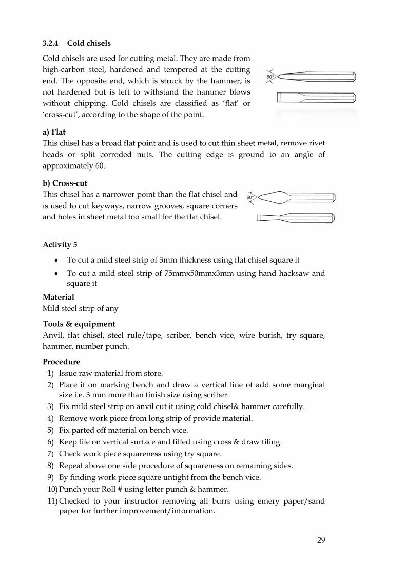
Cold chisels are used for cutting metal. They are made from high-carbon steel, hardened and tempered at the cutting end. The opposite end, which is struck by the hammer, is not hardened but is left to withstand the hammer blows without chipping. Cold chisels are classified as ‘flat’ or ‘cross-cut’, according to the shape of the point.
a) Flat This chisel has a broad flat point and is used to cut thin sheet metal, remove rivet heads or split corroded nuts. The cutting edge is ground to an angle of approximately 60.
b) Cross-cut This chisel has a narrower point than the flat chisel and is used to cut keyways, narrow grooves, square corners and holes in sheet metal too small for the flat chisel.
Activity 5
To cut a mild steel strip of 3mm thickness using flat chisel square it
To cut a mild steel strip of 75mmx50mmx3mm using hand hacksaw and square it
Material Mild steel strip of any
Tools & equipment Anvil, flat chisel, steel rule/tape, scriber, bench vice, wire burish, try square, hammer, number punch.
Procedure 1) Issue raw material from store. 2) Place it on marking bench and draw a vertical line of add some marginal
size i.e. 3 mm more than finish size using scriber. 3) Fix mild steel strip on anvil cut it using cold chisel& hammer carefully. 4) Remove work piece from long strip of provide material. 5) Fix parted off material on bench vice. 6) Keep file on vertical surface and filled using cross & draw filing. 7) Check work piece squareness using try square. 8) Repeat above one side procedure of squareness on remaining sides. 9) By finding work piece square untight from the bench vice. 10) Punch your Roll # using letter punch & hammer. 11) Checked to your instructor removing all burrs using emery paper/sand
paper for further improvement/information.

30
Safety Precautions 1) Fix tightly long strip of mild steel while cutting on anvil. 2) Clamp work piece tightly near to avoid catter while manual cutting. 3) Carefully checked the squareness using try square.
2.7 Scrapers
Scraping, unlike filing or chiselling, is not done to remove a great deal of mate-rial. The material is removed selectively in small amounts, usually to give a flat or a good bearing surface. A surface produced by machining or filing may not be good enough as a bearing where two surfaces are sliding or rotating. The pur-pose of scraping is therefore to remove high spots to make the surface flat or circular, and at the same time to create small pockets in which lubricant can be held between the two surfaces.
Surface plates and surface tables are examples of scraping being used when flat-ness is of prime importance. Examples where both flatness and lubricating pro-perties are required can be seen on the sliding surfaces of centre lathes and milling, shaping and grinding machines. The flat scraper, for use on flat surfaces, resembles a hand file thinned down at the point, but it does not have any teeth cut on it. The point is slightly curved, and the cutting edges are kept sharp by means of an oilstone. The scraper cuts on the forward stroke, the high spots being removed one at a time by short forward strokes. The flatness is checked with reference to a surface plate.

31
2.8 Engineer’s hammers
The engineer’s hammer consists of a hardened and tempered steel head, varying in mass from 0.1 kg to about 1 kg, firmly fixed on a tough wooden handle, usually hickory or ash. The flat striking surface is known as the face, and the opposite end is called the pein. The most commonly used is the ball-pein which has a hemispherical end and is used for riveting over the ends of pins and rivets.
For use with soft metal such as aluminium or with finished components where the work piece could be damaged if struck by an engineer’s hammer, a range of hammers is available with soft faces, usually hide, copper or a tough plastic such as nylon. The soft faces are usually in the form of replaceable inserts screwed into the head or into a recess in the face. Always use a hammer which is heavy enough to deliver the required force but not too heavy to be tiring in use. The small masses, 0.1 kg to 0.2 kg, are used for centre punching, while the 1 kg ones are used with large chisels or when driving large keys or collars on shafts. The length of the handle is designed for the appropriate head mass, and the hammer should be gripped near the end of the handle to deliver the required blow. To be effective, a solid sharp blow should be delivered and this cannot be done if the handle is held too near the hammer head. Always ensure that the hammer handle is sound and that the head is securely fixed.
2.8 Taps
Tapping is the operation of cutting an internal thread by means of a cutting tool known as a tap. When tapping by hand, straight-flute hand taps are used. These are made from hardened high-speed steel and are supplied in sets of three. The three taps differ in the length of chamfer at the point, known as the lead. The one with the longest lead is referred to as the taper or first tap, the next as the second or in-termediate tap and the third, which has a very short lead, as the bottoming or plug tap, A square is provided at one end so that the tap can be easily rotated by holding it in a tap wrench, The chuck type of wrench is used for the smaller tap sizes.

32
The first stage in tapping is to drill a hole of the correct size. This is known as the tapping size and is normally slightly larger than the root diameter of the thread shows the tapping sizes for ISO metric threads which have replaced most threads previously used in Great Britain. Tapping is then started using the taper or first tap securely held in a tap wrench. The long lead enables it to follow the drilled hole and keep square. The tap is rotated, apply-ing downward pressure until cutting starts. No further pressure is required, since the tap will then screw itself into the hole. The tap should be turned back quite often, to help clear chips from the flutes. If the hole being tapped passes through the compo-nent, it is only necessary to repeat the operation using the second or intermediate tap. Where the hole does not pass through – known as a blind hole – it is necessary to use the plug or bottoming tap. This tap has a short lead and therefore forms threads very close to the bottom of the hole. When tapping a blind hole, great care should be taken not to break the tap. The tap should be occasionally withdrawn completely and any chips be removed before proceeding to the final depth.
2.9 Dies
Dies are used to cut external threads and are available in sizes up to approxi-mately 36 mm thread diameter. The common type, for use by hand, is the cir-cular split die, made from high-speed steel hardened and tempered and split at one side to enable small adjustments of size to be made,
The die is held in a holder known as a die stock, which has a central screw for adjusting the size and two side locking screws which lock in dimples in the outside diameter of the die. The die is inserted in the holder with the split lined up with the central screw. The central screw is then tightened so that the die is expanded, and the two side locking screws are tightened to hold the die in posi-tion. Dies have a lead on the first two or three threads, to help start cutting, but it is usual also to have a chamfer on the end of the component. The die is placed squarely on the end of the bar and is rotated, applying downward pressure until cutting starts, ensuring that the stock is horizontal.

33
No further pressure is required, since the die then screws itself forward as cutting proceeds. The die should be rotated backwards every two or three turns, to break up and clear the chips. The thread can now be checked with a nut. If it is found to be tight, the central screw is slackened, the side locking screws are tightened, and the die is run down the thread again. This can be repeated until the final size is reached. As with tapping, easier cutting and better threads are produced when a proprietary cutting compound is used.
Activity 6
To cut internal thread of 3/8” in a hole
To cut external threads 3/8” on mild steel rod
Task 3
Open link given and describe difference between coarse and fine threads and also write & draw tools, procedure & precautions of making bolts of 3/8” 16 using die http://www.boltdepot.com/fastener-information/printable-tools/us-hex-bolt-sizes.pdf
Write the tools, procedure & precautions of making nut of 3/8” thread nut of corner to corner size ¾” using Tap.


35
4 Sheet Metal Operations
Learning Objectives
Upon completion of this unit the learner will be able to:
Describe sheet metal operations
Describe cutting and bending of sheet
Describe development of cylinder & cone.
Preface
Many products are made by sheet metal of different thickness depending on the strength and durability of created product. In our daily life we see many products which are from sheet metal to different shape. These products are used for housekeeping in any field domestic to industrial levels. To create different sheet metal products, different machine and tools are used. We will discuss in detail in this chapter.
4.1 Introduction
Many engineering components are produced from a flat sheet of metal which is cut to shape and then folded to form the finished article. The edges are then secured by a variety of methods such as welding, brazing, soldering and riveting. The accuracy of the size and shape of the finished article depends upon the accu-racy of drawing the shape on the flat sheet, known as the development. Allowance is made at this stage for folding or bending, the amount varying with the radius of the bend and the metal thickness.

36
4.2 Sheet Metal Operations
The thickness of metal sheet is identified by a series of numbers known as standard wire gauge, or SWG. Table 4.1 lists the most frequently used gauges and gives their thickness in millimetres.
Cutting is carried out using simple snips for thin-gauge steel up to around 20 SWG, treadle-operated guillotines capable of cutting 14 SWG steel, and hand-lever shears for sheet up to 1.5 mm thick. Holes and apertures can be cut using a simple hand-operated punch or a punch and die fitted in a fly press. For simple bends in thin material, bending can be carried out in a vice. For bends in thicker material with a specific bend radius, folding machines give greater accuracy with less effort.
4.2.1 Cutting and bending sheet metal
Light-gauge metal can be easily cut using snips. These may have straight or curved blades, Figure 1, the latter being used to cut around a curved profile. Lengths of handle vary from 200 mm to 300 mm, the longer handle giving greater leverage for cutting heavier gauge material. For cutting thicker metals, up to 1.5 mm, hand-lever shears are available, usually bench-mounted, Figure 2.
Figure 1 Straight- and curved-blade

37
The length of the lever and the linkage to the moving shear blade ensure adequate leverage to cut the thicker metals. Where larger sheets are required to be cut with straight edges, the guillotine is used. Sheet widths of 600 mm _ 2 mm thick and up to 1200 mm _ 1.6 mm thick can be accommodated in treadle-operated guillotines, Figure 3.
Figure 2 Hand-lever
Figure 3 Treadle
These have a moving top blade, which is operated by a foot treadle, and a spring which returns the blade to the top of its stroke. The table is provided with guides, to maintain the cut edges square, and adjustable stops to provide a constant size over a number of components. When the treadle is operated, a clamp descends to hold the work in position while cutting takes place, and this also acts as a guard to prevent injury. These machines can be extremely dangerous if not used correctly, so take great care.
When holes are to be cut in sheet metal, this can be done simply and effectively using ‘Q-Max’ cutters as shown in Figure 4. A pilot hole is drilled in the correct position, the screw is inserted with the punch and die on either side of the sheet, and the screw is tightened. The metal is sheared giving a correct size and shape of hole in the required po-sition.
Figure 4 “Q‐Max” Cutter

38
Where a number of components require the same size hole in the same position, it may be economical to manufacture a punch and die for the operation. The operation is carried out on a fly press, Figure 5, with the punch, which is the size and shape of the hole required, fitted in the moving part of the press.
Figure 5 Fly-press
The die, which contains a hole the same shape as the punch, but slightly larger to give clearance, is clamped to the table directly in line with the punch. When the handle of the fly press is rotated, the punch descends and a sheet of metal inserted between the punch and die will have a piece removed
the same shape as the punch, Figure 6.
With the use of simple tools, the fly press can also be used for bending small components, Figure 7. The top tool is fixed to the moving part and the bottom tool, correctly positioned under the top tool, is fixed to the table of the press. Metal bent in this way will spring back slightly, and to allow for this the angle of the tool is made less
ጘᘀ ᘆ襨� 唀 腨Ĉ ᘆ襨� ᔗ�ild steel, an angle of 88_ is sufficient for the component to spring back to 90_.
Figure 6 Punch and die in fly
Figure 7 Bending tool in fly

39
The simplest bends can be produced by holding the component in a vice and bending it over using a soft hammer. If the component is wider than the vice jaws, it can be clamped between metal bars. Unless a radius is put on one of the bars, this method produces a sharp inside corner, which may not always be desirable. Folding machines, Figure 8, are used with larger work of thicker gauges and for folding box sections. The top clamping beam, is adjustable to allow for various thick-nesses of material and can be made up in sections known as fingers to accommodate a previous fold. Slots between the fingers allow a previous fold not to interfere with further folds, as in the case of a box section where four sides have to be folded. The front folding beam, pivoted at each end, is operated by a handle which folds the metal past the clamping blade, Figure 9.
Figure 9 Folding
4.2.2 Development
The development of sheet-metal components ranges from the simple to the extre-mely complex. Let us consider three simple shapes: a cylinder, a cone and a rec-tangular tray. If a cylinder is unfolded, like unrolling a carpet, the length of the development is equal to the circumference, Figure 10. If a cone is unfolded while pivoting about the apex O, the development is a segment of a circle of radius Oa whose arc ab is equal in length to the circumference of the base, Figure 11.
Figure 10 Development of cylinder
Figure 11 Development of cone
Figure 12 Development of part
Figure 8 Folding machine

40
To find the length of arc ab, the base diameter is equally divided into 12 parts. The 12 small arcs 1–2, 2–3, etc. are transferred to the arc with point 12 giving the position of point b. A part cone (frustum) is developed in exactly the same way, with the arc representing the small diameter having a radius Oc, Figure 12. In practice, the circumference must take account of the material thickness. Any metal which is bent will stretch on the outside of the bend and be compressed on the inside. Unless the metal is of very light gauge, an allowance must be made for this. The allowance is calculated on the assumption that, since the outside of the bend stretches and the inside is compressed, the length at a distance half way between the inside and outside diameters, i.e. the mean diameter, will remain unchanged.
Activity 7
Cut five strips from sheet of 18 SWG of 12x75 using snip
Draw development layout of metallic box of 6”x 2”x1” on sheet metal of 10SWG and fabricate it also write down tools, procedure, safety precaution of making it.
Task 4
Draw the development of a solid paper cylinder of dia 60 mm and height of 120 mm on drawing sheet and make it physically use glue or any adhesive material. Link for concept: http://www.korthalsaltes.com/model.php?name_en=cylinder
Draw the development of a paper cone whose base dia is 60 mm and height of 100 mm on drawing sheet and make it physically use glue or any adhesive material.