mechanical engineering - ellon...
TRANSCRIPT

Mechanical Engineering
Name Class Teacher
Ellon Academy Technical Faculty

1
Learning Intentions I will learn about Mechanical symbols I will learn about the types of motion and how they relate to
each other I will learn about several different types of gearing systems I will learn how to use calculations to work out gear speeds I will learn how to use calculations to work out gear ratios I will learn about torque and how to work it out I will know about brakes, clutches and bearings, and how they
are used in mechanical systems
Success Criteria I can investigate a range of complex mechanisms by: Using the systems approach to analyse mechanisms and
structures (identifying key elements and sub-sections) Describing or drawing diagrams of a range of complex
mechanisms (Complex mechanisms should include at least one of brakes, clutches, couplings or bearings)
I can develop mechanical solutions to solve complex problems by: Identifying key aspects of the problem and identify all key aspects
(such as inputs, loads and control requirements). Applying knowledge and understanding of mechanisms Carrying out calculations to assist the selection of materials or
component sizes Designing, build and evaluate a mechanical solution to a complex
problem
To access video clips that will help on this course go to www.youtube.com/MacBeathsTech

2
Mechanical Symbols
Description Description Description Symbol Symbol Symbol
Linear
Rotational
Reciprocating
Oscillating
Fulcrum
Lever & Fulcrum
Shaft
Bearings
Coupling
Flexible Coupling
CAM
Belt Drive
Chain Drive
Fly Wheel
Governor
Ratchet
Pump
Compression Spring
Tension Spring
Torsion Spring
Torsion Spring
Simple Gear Train
Simple Gear Train
Bevel Gears
Worm & Wheel

3
What is Mechanical Engineering? Mechanical engineering is a diverse subject that derives its breadth from the need to design and manufacture everything from small individual parts and devices (e.g., micro scale sensors and inkjet printer nozzles) to large systems (e.g., spacecraft and machine tools). The role of a mechanical engineer is to take a product from an idea to the marketplace. In order to accomplish this, a broad range of skills are needed.
Mechanical engineers play a central role in such industries as automotive (from the car chassis to its every subsystem—engine, transmission, sensors), aerospace (airplanes, aircraft engines, control systems for airplanes and spacecraft), biotechnology (implants, prosthetic devices, fluidic systems for pharmaceutical industries), computers and electronics (disk drives, printers, cooling systems), energy conversion (gas turbines, wind turbines, solar energy, fuel cells), environmental control (air-conditioning, refrigeration, compressors); automation (robots, data and image acquisition, recognition, control), manufacturing (machining, machine tools, prototyping, micro fabrication)…..etc
To put it simply, mechanical engineering deals with anything that moves.
This unit will build on skills learned in National 5 Engineering Science in order to further deepen your understanding of Electronics to enable you to design your own working systems and give you a deeper insight into a possible career route.

4
What is a Mechanical System? A mechanism is a system of moving parts that changes an input motion and force into a desired output motion and force. Mechanisms are a large part of modern society. Most of the mechanisms are that we use everyday are so familiar that we never think twice about them, for example door handles, light switches, scissors. Mechanisms play a vital role in industry. While many industrial processes now have electronic control systems, it is still mechanisms that provide he muscle to do the work. They provide the forces to press sheet steel into shapes of car body panels, to lift large components from place to place and to force power hacksaws to cut through metal bars – the list is endless. It is only by using mechanisms that industry can make products you use every day. All mechanisms must:
Involve some kind of motion Involve some kind of force Make a job easier to do Need some kind of input to make them work Produce some kind of output

5
Motion There are four basic kinds of motion.
Rotary
Turning in a circle. This is the most common type of movement, for example wheels, clock hands, compact discs, CD-ROMs.
Linear
Movement in a straight line, for example movement of a paper trimmer cutting a straight edge on paper or a lift moving between floors. Reciprocating Backwards and forwards movement in a straight line, for example the needle in a sewing machine or the piston in a car engine.
Oscillating
Swinging backwards and forwards in an arc, for example the pendulum of a clock, a playground swing or a rocking horse.

6
Task 1 What types of motion do the following sports or leisure activities show when they are being used or carried out?

7
Gears Gears are toothed wheels designed to transmit rotary motion and power from one part of a mechanism to another. They are fitted to shafts with special devices called keys (or splines) that ensure that the gear and the shaft rotate together. Gears are used to increase or decrease the output speed of a mechanism and can also be used to change the direction of motion of the output. Simple Gear Train Gears work by interlocking or meshing the teeth of the gears together as shown. When 2 or more gears are meshed they form a gear train. The input gear which causes the system to move is called the driver and the output gear is called the driven. Idler Gear To get the driven gear to rotate in the same direction as the driver a third gear is inserted in the system. The idler gear has no effect on the speed of the driven gear wheel.
DRIVEN DRIVER
IDLER GEAR

8
Compound Gear Trains If gears are required to produce a very large change in speed, for example 100:1 then problems can arise with the size of gear wheels if a simple gear train is used. The problem can be overcome by mounting pairs of gears on the same shaft as shown.
Ratchet and Pawl
A wheel with saw shaped teeth round its rim is called a ratchet. The ratchet wheel usually engages with a tooth shaped lever called a pawl. The purpose of the pawl is to allow rotation in one direction only and prevent rotation in the opposite direction.

9
Worm and wheel
Another way of making larger speed reductions is to use a worm and wheel. The worm, which looks rather like a screw thread, is fixed to the driver shaft (sometimes directly onto the motor shaft). It meshes with a worm wheel, which is fixed to the driven shaft. The driven shaft runs at 90’ to the driver shaft. You should think of the worm wheel as a gear with only 1 tooth. This allows a huge reduction in speed which takes up very little space. Worm and Nut The worm gear is fixed so that when it spins, it moves the block. This transmits the motion through the gear. This allows for a big change in speed and increased torque Bevel gears
Bevel gears, like worm wheels, use shafts at 90’ to each other. A whisk which uses bevel gears to change the direction motion through 90’ as does the gears in a wind turbine.

10
Rack & Pinion A rack & pinion mechanism is used to transform rotary motion into linear motion, or linear motion into rotary motion. A round spur gear, the pinion, meshes with a rack that can be thought of as a spur gear with teeth set in a straight line. Gear wheels are normally made from metal or plastic. Plastic gears have the advantage that they are much quieter running and need less lubrication.
Crank & Slider
Crank & slider mechanisms involve changes between rotary and reciprocating motion. The crank rotates while the slider reciprocates. The longer the crank the further the slider will move.
http://goo.gl/anZAui

11
CAMS A cam is a specifically shaped piece of material, which can be used to change an input rotary motion to an output motion that is oscillating or reciprocating. The cam operates by guiding the motion of a follower held against the cam, either by its own weight or by a spring. As the cam rotates the follower moves. The way that it moves and the distance it moves depends on the cam’s shape and dimensions.
Cam Motion
Pear-shaped cams are often used for controlling valves. For example they are often used on motor-car cam shafts to operate the engine valves. A follower controlled by a pear-shaped cam remains motionless for about half a revolution; during the other half revolution of the cam the follower rises and falls. As the pear-shaped cam is symmetrical, the rising motion is the same as the falling motion. When the follower is not moving we call this the dwell part of the cam. In a car engine, cams are fixed on a camshaft. As each cylinder has two valves, an inlet and an exhaust valve, there are two cams on a camshaft for each cylinder as shown.
http://www.bbc.co.uk/schools/gcsebitesize/design/systemscontrol/mechanismsrev4.shtml

12
Belt Drives
To make rotary motion useful it has to be transmitted from one part of a machine to another, often with a change in speed. Connecting too many gears together can result in large efficiency losses through friction. A simple way of transmitting this motion would be to use a belt wrapped around 2 pulleys, the belt can be tightened or tensioned by a jockey wheel A jockey wheel is a specific part of a belt system which ensures tension is within the belt. Without this the belt could slip due to it being too slack. The jockey wheel is a small wheel that pushes or pulls on the belt to ensure tightness. This will cause no change in speed or direction to the system.
Changes in direction can be achieved by crossing over the belts. An advantage of using a belt drive is that it allows slippage in machines where you wouldn’t want for example a motor to stop or possibly cease because the belt won’t turn.

13
Types of Belt
There are 3 types of belt that are commonly used: Flat Belts, V Belts, and Toothed Belts
Flat Belt
A flat belt is known as this because they are flat. It will allow slip when it is needed, but it also has a tendency to slip when a large load is applied as there is not enough friction between the belt and the pulleys for it to grip.
V Belt
A V belt, sometimes known as a Vee Belt, is known as this due to its V cross sectional shape. This fits into a pulley that has a V shaped groove within it. Due to it having more contact with the wheel it allows for more tension to be created. As the load on the belt increases, it wedges further into the groove, improving torque and transmission.
Toothed belts
Belt drives tend to use their ability to slip to their advantage, however where slippage would damage a mechanism toothed belts have been developed that retain the advantages of normal belts but do not slip.
V Belt
Flat Belt
Toothed Belt

14
Chain Drive Systems The major drawback of a belt system is that it could slip – even when it is properly tensioned. If you do not want slippage you can use a chain drive along with a toothed wheel called a sprocket.
Just like a belt, a chain drive needs to be properly tensioned, and this is usually done with a spring loaded jockey wheel. Couplings Rotary machines employ a variety of methods of transmitting motion from one part of a machine to another. The motion is often transmitted through shafts, which are round metal rods. To connect shafts we can use two types of couplings, flange and muff. If shafts are not aligned (centres do not match up) we can use flexi-coupling or universal joints.

15
Movement-Multiplier Ratio in gears The ratio of change in speeds between the gears is called the movement-multiplier ratio. The ratio of a gear system is found by dividing the number of teeth on the driven gear by the number of teeth on the driver gear. This can be used to calculate the output speed of a gear system.
MMR = Number of teeth on driven gear Number of teeth on driver gear
Example To work out this gear system the gear multiplier ratio is: Gear Ratio = 12 = 1 OR 1:2 24 2 This means that if gear A was rotating at 100 rpm clockwise then gear B would rotate at 200rpm anti-clockwise.
Gears can also be used to decrease the speed of a mechanism. Gear ratio = 24 = 2 OR 2:1 12 1 If gear A is still rotating at 100 rpm in a clockwise direction then gear B will now rotate at 50 rpm in an anticlockwise direction.
The Driver will be going at TWICE the speed of the driven
The Driven will be going at HALF the speed of the driver
http://goo.gl/sEJXZZ

16
Compound Gears If gears are required to produce a very large change in speed, for example 100:1 then problems can arise with the size of gear wheels if a simple gear train is used. The problem can be overcome by mounting pairs of gears on the same shaft as shown. This diagram shows how the shafts are connected between the ‘pairs’ of gears. Gears B and C are connected and rotate at the same speed. To calculate the multiplier ratio for the gear train it is necessary to calculate the ratio for each pair of meshing gears. Example The multiplier ratio for this gear system would be… The multiplier ratio for the first pair of meshing teeth is: Ratio of AB = driven = 80 = 4 = 4:1 Driver 20 1 The multiplier ratio for the second pair of meshing teeth is: Ratio of CD = driven = 60 = 6 = 6:1 Driver 10 1 The total multiplier ratio is calculated by multiplying both ratios: Total ratio = 4 x 6 = 24 = 24:1 1 1 1
For an input speed of 100 rpm, the output speed would be 4.17 rpm (100 ÷ 24)
1

17
Task 2 A solar-powered water-pumping system is being tested for use in developing countries. a) Calculate the output speed of Mechanism A. b) State the name of Mechanism B.

18
Task 3 A model train climbs a steep slope at an amusement park. A simplified diagram of the train drive system is shown here. a) State the names of the labelled parts of the drive system in the diagram above.
Part X:
Part Y:
b) A simplified diagram of the train drive system is shown. Calculate the speed of the 90 tooth gear.
19
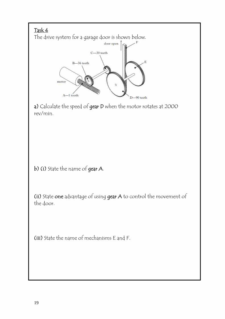
Task 4 The drive system for a garage door is shown below. a) Calculate the speed of gear D when the motor rotates at 2000 rev/min. b) (i) State the name of gear A. (ii) State one advantage of using gear A to control the movement of the door. (iii) State the name of mechanisms E and F.

20
Velocity Ratio We can work out the overall ratio of a gearing system by only knowing the input and output speeds. This is known as the velocity ratio. The velocity ratio for a gearing system is the ratio of the number of revolutions made by the input to the number of revolutions made by the output.
VR = Speed of input Speed of output Example The drive system used in an airport luggage conveyor is shown below. VR = INPUT = 1200 = 400 = 400:1 OUTPUT 3 1
21
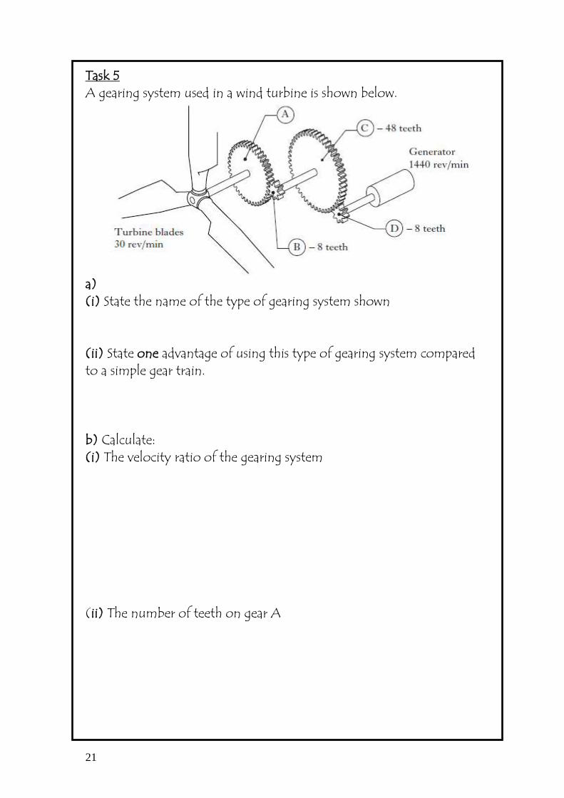
Task 5 A gearing system used in a wind turbine is shown below.
a) (i) State the name of the type of gearing system shown (ii) State one advantage of using this type of gearing system compared to a simple gear train. b) Calculate: (i) The velocity ratio of the gearing system (ii) The number of teeth on gear A

22
Task 6 A gear system for operating a theatre curtain is shown below. Calculate: a) The velocity ratio of the system when gear D rotates at 150 rev/min. b) The ratio of gear B to gear A; c) The number of teeth on gear D to produce the correct output speed. d) State one advantage of a gear system made from plastic rather than steel gears.

23
Torque and Drive Systems
Torque is the amount of turning produced by a force. The turning or twisting action or exerted by a force, or a number of forces, will cause, or tend to cause rotary motion.
Example 1 How much torque is required to tighten the nut if the force required is 45N and the radius of the tool is 200 mm. torque = force x radius = 45 N x 200 mm Task 7 A flag is raised by a small hand winch. The cord passes around a drum of 100mm diameter. Calculate the torque on the drum due to the tension on the rope of 9.3N.

24
Task 8 A simple winding arrangement used for raising oil barrels from one level to another is shown below. The winding drum has a diameter of 300 mm and the total amount of oil being raised has a mass of 160 kg. a) (i) Calculate the weight of oil being raised. ii) If an empty barrel has a weight of 285N, calculate the total torque required to raise a barrel full of oil. b) Describe how the system could be altered in order to increase the torque of the winding arrangement.

25
Task 8 (continued) c) The system was modified to include the mechanism shown below. State the names of the mechanism’s parts.
Part A: Part B:
d) Describe why this mechanism would be useful as part of the winding arrangement. Task 9 A winch system used to raise a 125N load is shown. a) If the windlass has a diameter of 300 mm, calculate the torque produced by the load.

26
Task 9 (continued) b) If the motor is rotating with a speed of 120 rpm, calculate the rotational speed of the windlass.

27
Friction
In more complex systems friction can be a major problem and engineers have developed various methods of reducing friction. The simplest way to reduce friction is to use a lubricant such as oil or grease. Lubricant Use a lubricant, such as oil or grease. By lubricating the moving parts, it allows the different parts to touch and move easier without creating as much heat. Bearings These are components that are designed to withstand wear. Ball and roller bearings are used within high speed and high force systems to replace any rubbing actions with rolling actions instead. Rolling doesn’t create as much friction as rubbing does. These bearings can eventually be removed and replaced instead of damaging and replacing the whole system. The bearing consists of an outer and an inner ‘race’ which have grooves machined in them. Hardened steel spheres, or ‘balls’, are fitted between the outer and inner race which can then rotate freely. To work effectively the ball bearing must be well lubricated. Friction is not all bad however and without friction many mechanical systems would not work. It is friction between the soles of our shoes and the pavement, which allows us to walk. If it were not for friction it would feel a bit like walking on ice and we would find it impossible to get about. Tyres on cars are designed to increase friction with the road surface to ensure that the force from the engine can be transmitted effectively.

28
Couplings
Rotary machines employ a variety of methods of transmitting motion from one part of a machine to another. The motion is often transmitted through shafts, which are round metal rods. Often these shafts must be connected together to transmit the motion. Shafts are joined using a device called a coupling. In small models, such as those used in schools, simple sleeves or tubes of plastic use friction to drive two shafts, which are pressed into the sleeve. Stronger couplings are required for industrial-sized machines. Aligned shafts Where shafts are in line with each other they are joined either with a flanged coupling or a muff coupling. All couplings must be ‘keyed’ to the shafts they are joining to give a positive drive. Below shows a flange coupling and a muff coupling.
flange coupling
muff coupling

29
SPIDER
FLEXIBLEDISC
Non-aligned shafts Where shafts meet at a slight angle, some method of compensating for misalignment must be used. Where the misalignment is small, a flexible coupling (flexi-coupling), using either rubber or a mixture of rubber and steel, is used. The rubber is flexible enough to compensate for small changes in angle.
flexi-coupling When the alignment is more than a few degrees out, a universal joint is used. A universal joint can transmit motion through an angle of 20 degrees. Below Hooke’s universal joint. The two yokes are free to pivot on the central ‘spider’. Modern universal joints use needle roller-bearings between the spider and the yokes.
Universal joints

30
RAMSLIDINGBEARING
SURFACES
BEARINGADJUSTMENT
MACHINECASTING
Bearings Parts of mechanisms that slide over each other use flat bearings. Flat bearings tend to be made from cast iron, brass or bronze. Brass and bronze bearings, which are softer than the materials sliding through or over them, will wear. They are sometimes called wear strips. When badly worn they are replaced. Cast iron is a self-lubricating material and is very strong when compressed.
a flat bearing and wear strip When a shaft is turned, it must be supported in some way. Friction opposes motion, and when a shaft is turning there is likely to be heat and wear at the supports. The amount of heat and wear due to friction will vary with the materials used, the forces involved and the speeds involved. Various types of bearing and bearing materials have been developed to reduce friction in mechanisms. Bearings that support a round shaft are called journal bearings. When a journal bearing has to take some axial load, it must have a shoulder to take this load. When a shaft has a large axial load, it must have a thrust bearing. Below shows a combined thrust and journal bearing.
combined thrust and journal bearing

31
CAP
TOP SHELL
OIL GROOVE
BOTTOM SHELLSUPPORT OR
HOUSING
SHAFT
LUBRICATOR
BEARING
OIL FILM
Journal bearings are made from a variety of materials: the most common are bronze and white metal. Bronze is used where slow, heavy loads are carried. White metal, an alloy of tin, copper and antimony, which is soft and melts when overheated, is used in systems with light loads. Plastic and nylon bearings are also very common. Split bearings As bearings are designed to wear, it stands to reason that they must be able to be removed and replaced. When the bearing support is at the start or end of a shaft, it is simple to remove and replace it. However, when a shaft is very long, it may be supported at several points along its length. To make it easy to remove and replace bearings, split bearings are used
a split bearing When the bearing wears, the bearing housing can be separated by removing the two nuts. The bearing shells can then be removed and replaced. Notice that the inside of the shells has a groove. This groove is normally fed by a reservoir of oil, which helps to lubricate the shaft and bearing, thus reducing friction. A car big end is a common example.

32
OUTER RACE
INNER RACE
BALL BEARING
CAGE
Ball-and-roller bearings Ball and roller bearings change the action of rubbing to that of rolling. Ball and roller bearings use hardened steel balls or rollers, which rotate inside an inner and outer case. The outer case or ‘race’ presses into a housing; the inner race is a press fit on the shaft. These bearings are used in high-speed, high-force applications.
ball and roller bearings
BALL THRUST BALL
ROLLER NEEDLE ROLLER

33
Clutches
We want to reduce friction in moving parts. To achieve this bearings are used, surface contact area is minimised and lubricants are used. However, without friction between the tyres and road, cars would not be able to stay on the roads or even start to move. Clutches are devices that allow two rotating shafts to be connected and disconnected. There are two types of clutch, the positive clutch and the friction clutch. A dog clutch is a positive clutch. This has four interlocking blocks (dogs) on one shaft that can be interlocked with four dogs on the other shaft.
a dog clutch When the clutch is engaged, the two dogs are interlocked and the drive shaft rotates the driven shaft. When the clutch is disengaged, the two shafts are separated. In clutch systems, the two shafts must be carefully aligned.

34
ENGAGED
DRIVER SHAFTIN MOTION
DRIVEN SHAFTSTATIONARY
Positive-drive clutches require the drive shaft to be stationary when the two clutch plates are brought together. Friction clutches can be engaged and disengaged while both shafts are still turning. Friction clutches rely on the friction between the plates to transmit the power from one shaft to another. Below shows a simple example of a friction clutch.
a simple friction clutch Below shows a multi-plate system used for large transmission forces or limited-space applications.
a multi-plate clutch

35
Task 10 An Electric Drive motor shaft is to be connected to an air compressor using a clutch. State one advantage and disadvantage of this coupling method, and explain your answers Advantage Disadvantage

36
Task 11 The load/eject mechanism on a Blu-ray disc drive is shown.
Identify key elements and sub-sections of the load/eject mechanism and describe how it operates.

37
Task 12 A manufacturer uses bearings to locate motorcycle wheels. Explain two functions of bearings. Function 1: Function 2:

38
Task 13 A number of different engineers would be involved in implementation of the bridge project, from design through to completion. Describe two examples of specialist skills and one example of specialist knowledge that a mechanical engineer would use. Skill 1: Skill 2: Knowledge: