mechanical characterisation of engineering materials
TRANSCRIPT

Mechanical Characterisation of Coatings and Composites-
Depth-Sensing Indentation and Finite Element Modelling
Zhi-Hui Xu
Doctoral Dissertation
Department of Materials Science and Engineering Royal Institute of Technology
Stockholm, Sweden 2004

ii
Akademisk avhandling som med tillstånd av Kungliga Tekniska Högskolan i Stockholm, framlägges för offentlig granskning för avläggande av teknologie doktorsexamen, fredagen den 28 maj 2004, kl. 10.00 i sal B1, Brinellvägen 23, KTH, Stockholm. ISBN 91-7283-719-5 ISRN KTH/MSE--04/17--SE+METO/AVH Zhi-Hui Xu Universitetsservice US AB Stockholm 2004

iii
To my wife Hong Yi and daughter Jia Qian

iv

v
Abstract In the past two decades depth-sensing indentation has become a widely used technique to measure the mechanical properties of materials. This technique is particularly suitable for the characterisation of materials at sub-micro or nano scale though there is a tendency to extend its application to the micro or macro scale. The load-penetration depth curve of depth-sensing indentation is a characteristic of a material and can be used for analysing various mechanical properties in addition to hardness. This thesis deals with the mechanical characterisation of bulk materials, thin films and coatings, gradient materials, and composites using depth-sensing indentation. Finite element method has been resorted to as a tool to understand the indentation behaviour of materials.
The piling-up or sinking-in behaviour of materials plays an important role in the accurate determination of materials properties using depth-sensing indentation. Finite element simulations show that the piling-up or sinking-in behaviour is determined by the material parameters, namely E/σy ratio and strain hardening exponent or experimental parameter he /hmax ratio, and the contact friction. An empirical model has been proposed to relate the contact area of indentation to the E/σy ratio and the he /hmax ratio and used to predict the piling-up or sinking-in of materials. The existence of friction is found to enhance the sinking-in tendency of materials. A general relationship between the hardness and the indentation representative stress valid for both soft and hard materials has been obtained. A possible method to estimate the plastic properties of bulk materials has been suggested.
Measuring the coating-only properties requires the indentation to be done within a critical penetration depth beyond which substrate effect comes in. The ratio of the critical penetration depth to the coating thickness determined by nanoindentation is independent of coating thickness and about 0.2 for gold / nickel, 0.4 for aluminium / BK7 glass, and 0.2 for diamond-like-carbon / M2 steel and alumina / nickel. Finite element simulations show that this ratio is dependent on the combination of the coating and the substrate and more sensitive to differences in the elastic properties than in the plastic properties of the coating/substrate system. The deformation behaviour of coatings, such as, piling-up of the soft coatings and cracking of the hard coatings, has also been investigated using atomic force microscope.
The constraint factors, 2.24 for WC phase and 2.7 for WC-Co cemented carbides, are determined through nanoindentation and finite element simulations. A modified hardness model of WC-Co cemented carbides has been proposed, which gives a better estimation than the Lee and Gurland hardness model. Finite element method has also been used to investigate the indentation behaviour of WC-Co gradient coatings. Keywords: depth-sensing indentation, nanoindentation, finite element method, atomic force microscope, mechanical properties, hardness, deformation, dislocations, cracks, piling-up, sinking-in, indentation size effect, thin coatings, composite, gradient materials, WC-Co, diamond-like-carbon, alumina, gold, aluminium, nickel, BK7 glass, M2 steel.

vi

vii
Preface This thesis, consisting of six chapters, has touched upon a few aspects concerning the mechanical characterisation of bulk materials, thin films and coatings, composite, and gradient materials with depth-sensing indentation. Finite element method has been resorted to as a tool to understand the indentation behaviour of materials. Chapter 1 gives a short introduction of hardness test, finite element modelling of indentation, and the aim of this thesis. Chapter 2 concerns some basic aspects of depth-sensing indentation including a introduction of the method, the determination of plastic properties, indentation size effects, and indentation deformation behaviour. Chapter 3 focuses on the determination of mechanical properties of thin films and coatings and the deformation behaviour of coatings. Chapter 4 deals with the mechanical properties of a particular composite, i.e. WC-Co cemented carbides and depth-sensing indentation of WC-Co gradient materials. Chapter 5 summarises the seven appended papers. The thesis ends with the conclusions and the suggestions for future work. The appendix contains the following papers: Paper I: Method to determine the plastic properties of bulk materials by
nanoindentation. Zhi-Hui Xu and David Rowcliffe 2002 Philosophical Magazine A vol. 82 pp. 1893-1901.
Paper II: An analysis of piling-up or sinking-in behaviour of elastic-plastic
materials under sharp indentation. Zhi-Hui Xu and John Ågren Accepted for publication in Philosophical Magazine.
Paper III: Deriving mechanical properties of soft coatings using nanoindenation: an
application of mechanism-based strain gradient plasticity. Zhi-Hui Xu and David Rowcliffe 2002 Surface and Coatings Technology vol. 157 pp. 231-237.
Paper IV. Nanoindentation on diamond-like-carbon and alumina coatings.
Zhi-Hui Xu and David Rowcliffe 2002 Surface and Coatings Technology vol. 161 pp.44-51.

viii
Paper V. Finite element analysis of substrate effects on indentation behaviour of thin films. Zhi-Hui Xu and David Rowcliffe 2004 Thin Solid Films vol. 447-448 pp.399-405.
Paper VI. A modified hardness model for WC-Co cemented carbides.
Zhi-Hui Xu and John Ågren Submitted to Materials Science and Engineering A.
Paper VII. Effect of cobalt content gradients on hardness of WC-Co coatings:
Finite element simulations. Zhi-Hui Xu and John Ågren 2003 Euro PM2003 Conference Proceedings Valencia Spain vol. 3 pp. 135-140.
Stockholm 2004 Zhi-Hui Xu

ix
List of symbols a : contact radius of indentation. aE : ratio of the elastic modulus of substrate to that of coating or film. aY : ratio of the yield stress of substrate to that of coating or film. Ac : projected contact area of indentation. b : Burgers vector. c : constraint factor of indentation hardness, c = H/σy or σr . C : contiguity of WC particles. d : particle size of carbide. E : elastic modulus or Young’s modulus of material. ECC : elastic modulus of cemented carbides. Ecom : composite modulus of the coating/substrate system. Ef : elastic modulus of coating or film. Ei : elastic modulus of indenter. Er : reduced modulus of indentation. Es : elastic modulus of indented specimen. Esub : elastic modulus of substrate. G : shear modulus. GCC : shear modulus of cemented carbides. GCo : shear modulus of Co phase. GWC : shear modulus of WC particles. h : penetration depth of indentation. hc : contact depth. hel : elastic recovered depth of indentation. hmax : maximum penetration depth of indentation. hs : deflection of the surface at the perimeter of contact. H : hardness. H0 : hardness in the absence of any geometrically necessary dislocations
or true hardness. Had : hardness of adhesive indentation. HCC : hardness of cemented carbides. HCo : hardness of Co phase. Hcom : composite hardness of the coating/substrate system. Hf : hardness of the coating or film. Hs : hardness of the substrate. Hsl : hardness of sliding indentation. HWC : hardness of WC particles. K : bulk modulus. KCC : bulk modulus of cemented carbides. KCo : bulk modulus of Co phase. KWC : bulk modulus of WC particles. l : indentation size effect index.

x
n : strain hardening exponent. P : indentation load. Pmax : maximum indentation load. Pr : test-specimen resistance. r : radius of the plastic deformed zone in soft coatings. rc : critical radius of the plastic deformed zone in soft coatings where
interaction between coating and substrate comes in. R : radius of spherical indenter. S : contact stiffness. t : coating thickness. VCo : volume fraction of Co phase. VWC : volume fraction of WC particles. εr : representative plastic strain of indentation. γ : angle between the surface of indenter and the contact surface. λ : mean free path of binder phase. µ : friction coefficient. µc : critical friction coefficient for adhesive contact. ν : Poisson’s ratio. νcom : composite Poisson’s ratio of the coating/substrate system. νi : Poisson’s ratio of indenter. νs : Poisson’s ratio of indented specimen. θ : half-tip angle of indenter. ρs : density of statistically stored dislocations. σCC : yield stress of cemented carbides. σCo : yield stress of Co phase. σf : yield stress of coating or film. σr : representative stress of indentation. σsub : yield stress of substrate. σWC : yield stress of WC particles. σy : yield stress.

xi
Contents ABSTRACT................................................................................................. V
PREFACE.................................................................................................VII
LIST OF SYMBOLS ................................................................................ IX
1 INTRODUCTION................................................................................1 1.1 HARDNESS TEST..............................................................................1 1.2 FINITE ELEMENT MODELLING OF INDENTATION...............................2 1.3 AIM OF THE PRESENT WORK ............................................................3
2 SOME ASPECTS OF DEPTH-SENSING INDENTATION...........5 2.1 DEPTH-SENSING INDENTATION METHOD .........................................5 2.2 DETERMINATION OF PLASTIC PROPERTIES OF MATERIALS BY DEPTH-SENSING INDENTATION................................................................................8 2.3 INDENTATION SIZE EFFECT............................................................10 2.4 INDENTATION DEFORMATION BEHAVIOUR ....................................13
3 DEPTH-SENSING INDENTATION OF COATINGS ..................19 3.1 THE CRITICAL PENETRATION DEPTH FOR COATING ONLY PROPERTIES MEASUREMENT. .....................................................................19 3.2 MODELS FOR DETERMINATION OF COATING PROPERTIES. .............21 3.3 INDENTATION DEFORMATION BEHAVIOUR OF COATINGS...............22
4 INDENTATION OF WC-CO GRADIENT MATERIALS ...........29 4.1 MODELS FOR MECHANICAL PROPERTIES OF WC-CO CEMENTED CARBIDES..................................................................................................29 4.2 DEPTH SENSING INDENTATION OF WC-CO GRADIENT COATINGS. .34
5 SUMMARY OF THE APPENDED PAPERS.................................37
6 CONCLUSIONS AND FUTURE WORK.......................................41 6.1 CONCLUDING REMARKS ................................................................41 6.2 SUGGESTIONS FOR FUTURE WORK.................................................42
ACKNOWLEDGEMENTS .......................................................................45
BIBLIOGRAPHY......................................................................................47 APPENDED PAPERS

xii

Zhi-Hui Xu , Ph. D. Thesis, MSE, KTH, 2004
1
1 Introduction
1.1 Hardness test For a long time hardness has been used to characterise the mechanical properties of materials and various methods have been developed to measure the hardness. Although these methods are simple, in principle, it is very difficult to precisely define a physically meaningful hardness to include all the various characteristics of materials that have been referred to as hardness. Depending on the measuring methods, hardness may have different meanings, scales, and units. For example, the Mohs hardness, which is widely used by mineralogists, is measured by scratching a solid against ten selected standard minerals ranging from the softest talc to the hardest diamond and has a scale from 1 to 10. On the other hand, the Brinell hardness and Vickers hardness, which are commonly used in materials science, are determined by deforming the material with an indenter and dividing the indentation load with the area of the residual indent, i.e., hardness has the same unit as pressure. Moreover, hardness is also found to vary with the indentation size. This phenomenon is known as the indentation size effect, which is often caused by the variation of deformation behaviour, surface condition, and microstructure of materials. In general, hardness may be defined as a measurement of the resistance of materials to the permanent deformation or damage.
Hardness tests usually fall into three main categories: scratch, static indentation, and rebound or dynamic hardness test (Tabor 1951, Mott 1956, McColm 1990). Among these three hardness tests, static indentation test is the most widely used and well-established method. Static indentation is normally performed by forcing an indenter with certain geometry into a well-polished surface of materials. The geometry of the indenter can be spherical (Brinell), conical (Ludwik), and pyramidal (Vickers, Knoop, Berkovich, and Cube Corner). The indentation hardness of materials is calculated by dividing the indentation load with the real surface area or the projected contact area of the impression. Conventionally the contact area is measured from the residual indents using an optical microscope, which may work well for indents with the size above micrometer. However for indentation made in sub-micro or nano regime, it is difficult to determine the contact area by the conventional method due to the resolution limit of the optical microscope.
Introduction
An alternative way to make indentation at sub-micro or nano scales is the so-called depth-sensing indentation, which is also often called instrumented indentation or nanoindentation test. In depth-sensing indentation, the indentation load and the penetration depth are continuously measured as a function of indentation time during the indentation and a load-penetration depth curve is obtained. The projected contact area of indentation under the maximum load is directly determined by analysing the load-penetration depth curve with the known geometry of the indenter. The hardness is then calculated by dividing the maximum load Pmax with the projected contact area Ac, that is,
H = (1.1) Pmax
Ac
Obviously, the hardness here has a well defined physical meaning and is the mean pressure that materials can withstand locally.
In fact, the load-penetration depth curve of depth-sensing indentation test provides plentiful information related with the deformation behaviour of materials and can also be used for analysing other mechanical properties of materials in addition to hardness. Those properties include the elastic modulus of material (Loubet et al. 1984, Doerner and Nix 1986, Oliver and Pharr 1992), which is another common property that can be determined from depth sensing indentation, yield stress and work hardening exponent (Field and Swain 1993, Robach et al. 1998, Giannakopoulos and Suresh 1999, Zeng and Chiu 2001, Dao et al. 2001, Xu and Rowcliffe 2002a, Mata and Alcala 2003, Bucaille et al. 2003), stress exponent for creep and strain rate sensitivity (Mayo and Nix 1988, Raman and Berriche 1992, Lucas and Oliver 1999), and fracture toughness (Lawn et al. 1980, Pharr 1998, Field et al. 2003). An accurate measure of those properties apparently requires a thorough understanding of the deformation behaviour of materials under indentation and robust models of mechanics for analysing the load-penetration depth curve of the indentation.
1.2 Finite element modelling of indentation Finite element modelling plays an important role in the study of indentation behaviour of materials. For indentation with an indenter with simple geometry, such as, flat punch (Sneddon 1946), sphere (Hertz 1882), and wedges or cones (Sneddon 1948), on an elastic half-space, analytic solutions for stresses and deformation have been available for many years. However, for indentation on inelastic solid, analytic solutions for stresses and deformation are insuperable due to the complexity of the non-linear behaviour of materials. Existing theoretical analyses of elastic-plastic indentation, such as, the slip-line field model (Hill 1950) or the cavity model (Johnson 1985), can only be applied to limited cases. For
2

Zhi-Hui Xu , Ph. D. Thesis, MSE, KTH, 2004
3
instance, the slip-line field model is based on two-dimensional (2D) indentation of a rigid plastic material while the cavity model assumes an elastic-perfectly-plastic behaviour of materials and a hemispherical fully plastic zone encased in an elastic surround under the indenter, which are rarely fulfilled in practice. Therefore, for most cases of inelastic indentation, analyses are normally done with the aid of finite element method.
Finite element analysis is very useful for indentation analysis and capable of giving insight into the indentation behaviour of materials. With an appropriate formulation and discretization of the indentation problem, finite element method has been successfully used to solve various indentation problems with sufficient accuracy, for example, indentations with different shapes of indenters, e.g. axisymmetric (2D) and pyramidal (3D), indentations on different materials, e.g. bulk materials, coatings, and gradient materials, and indentations with different boundary conditions, e.g. contacts with or without friction, etc (Bhattacharya and Nix 1991, Laursen and Simo 1992, Giannakopoulos et al. 1994, Biwa and Storåkers 1995, Larsson et al. 1996, Gianakopoulos and Suresh 1997, Mesarovic and Fleck 1999, Giannakopoulos 2002). Detailed information about indentation, such as, the stress and strain distribution, the influence of material properties on the indentation behaviour, and the effect of the imperfection or deformation of the indenter, can also be obtained directly from finite element simulations. Besides, the availability of the powerful commercial finite element softwares and the high-speed computers makes the finite element modelling much easier and the simulation process much faster.
1.3 Aim of the present work Depth-sensing indentation test has been widely used to measure the mechanical properties of materials. The load-penetration depth curve obtained by depth-sensing indentation is a characteristic of a material. Accurate determination of mechanical properties from the load-penetration depth curve demands a full comprehension of the indentation behaviour of the material, such as, how the load-penetration depth curve is related to the mechanical properties of materials, and how the deformation behaviour, e.g. piling-up or sinking-in, is influenced by the variation of the mechanical properties of materials. The first part of the present thesis (Paper I and II) focuses on the indentation behaviour of elastic-plastic strain-hardening materials.
Indentation on thin films and coatings is more complicated compared with indentation on bulk materials. The measurement of coating-only properties requires elimination of the substrate effects by either making indentation within a critical penetration depth beyond which the substrate effects come in or using the empirical or analytical models. Indentation size effects must be also considered in the real test since the penetration depth of indentation on thin films and coatings is

Introduction
4
usually very shallow in order to avoid the substrate effects. Thus it is very important to know how the critical penetration depth and the deformation behaviour of the coating system vary with the different coating/substrate systems. This topic is dealt in the second part of the present thesis (Paper III, IV, and V).
In the manufacture of coatings, the material properties of coating and substrate are usually different and an abrupt transition between coating and substrate, which often results in a high local stress concentration, should be avoided. Instead, a gradual change of the materials composition and properties is preferred to mitigate the stress concentration, which may cause the failure of coatings during the process of manufacture and application. Moreover, building a gradient of the mechanical properties also provides a possibility to ‘tailor’ the mechanical properties of gradient materials according to the application requirements. So knowledge of the variation of the mechanical properties, e.g. hardness, with the existing gradients is certainly an advantage for the design and manufacture of the gradient materials. The third part of the present thesis (Paper VI and VII) covers some aspects of hardness prediction of WC-Co cemented carbides and the influence of Co content gradient on the hardness of WC-Co gradient materials.

Zhi-Hui Xu , Ph. D. Thesis, MSE, KTH, 2004
2 Some aspects of depth-sensing indentation
2.1 Depth-sensing indentation method Depth-sensing indentation is a novel technique developed in the past two decades for measuring the mechanical properties of materials (Pethica et al. 1983, Loubet et al. 1984, Doerner and Nix 1986, Oliver and Pharr 1992). This technique is based on high-resolution instruments that continuously monitor the loads and displacements of an indenter as it is pushed into and withdrawn from a material. The load-displacement data obtained from the indentation process, which is often referred to as load-penetration depth curve of indentation, may contain information about elastic deformation, plastic deformation, fracture, and creep of materials and can be used to derive various mechanical properties of materials, most commonly, the hardness and elastic modulus. An obvious advantage of depth-sensing indentation test over conventional hardness test is that the contact area of depth-sensing indentation can be directly determined from the load-penetration depth curve with the known geometry of the indenter. This feature makes the depth-sensing indentation test particularly suitable for measuring the mechanical properties of materials at small scales where accurate determination of the contact area would be an extremely difficult task for conventional hardness test. Therefore depth-sensing indentation sometimes is also called nanoindentation.
A typical load-penetration depth curve of depth-sensing indentation consists of two parts, loading and unloading, as shown in Fig. 2.1. The loading part normally includes the elastic-plastic deformation of material and can be expressed as
P = (2.1) Ah2
where P is the indentation load, h is the penetration depth measured from surface, and A is a constant that is dependent on the geometry of the indenter and the mechanical properties of material. The relationship in Eq. (2.1) has been confirmed by the experiments (Hainsworth et al. 1995, Sakai and Nakano, 2002), the finite element analyses (Giannakopoulos et al. 1994, Larsson et al. 1996), and the dimensional analysis (Cheng and Cheng, 1998a, 1999) of indentation on elastic-plastic materials.
The unloading part of the indentation load-penetration depth curve, which is mainly elastic, can be described by
5

Some aspects of depth-sensing indentation
6
= BhelmP (2.2)
where hel is the elastic depth of the indentation, B is a constant that is related to the elastic properties of materials and the geometry of indenter, and m is a constant, which equals 1, 1.5, and 2 for a flat cylinder punch, sphere or parabola of rotation, and cone, respectively (Sneddon 1965). Experiments conducted on a variety of materials have revealed that the unloading curve is well-described by Eq. (2.2) with a modification of the surface perturbation (Oliver and Pharr, 1992), that is,
P = B(h − hf )m (2.3)
where hf is the final penetration depth after complete unloading. The value of m obtained from the indentations of different materials ranges from about 1.2 to 1.5 for Berkovich indentation (Oliver and Pharr 1992) and equals 2 for Vickers indentation (Sakai 2003).
Fig. 2.1. A typical load-penetration depth curve of depth-sensing indentation.

Zhi-Hui Xu , Ph. D. Thesis, MSE, KTH, 2004
Fig. 2.2. Schematic of a cross-section of an indentation and the parameters used in the analysis (Oliver and Pharr 1992).
A crucial step to determine the hardness and elastic modulus of materials from
analysing the load-penetration depth curve of indentation is the calculation of the projected contact area of indentation under peak load. Two things must be known in order to determine the projected contact area. One is the geometry of the indenter, i.e. the area function, A = f (h), that relates the cross-sectional area of the indenter to the distance from its tip. This area function can be determined using either direct methods, such as, directly measuring the indents made on soft material with transmission electron microscope (Pethica et al. 1983) or the indenter itself with a scanning force microscope (Herrmann et al. 2000), or indirect methods, such as, the calibration method suggested by Oliver and Pharr (1992). The other parameter needed for the calculation of the projected contact area is the contact depth at peak load. As shown in Fig. 2.2, the contact depth at peak load is given by
hc = hmax − hs (2.4) where hc is the contact depth, hmax is the maximum penetration depth, which can be directly determined from the load-penetration depth curve, and hs is the deflection of the surface at the perimeter of the contact, which is given by Sneddon’s equation (Sneddon 1965)
hs = ε (2.5) Pmax
S where ε is a geometric constant and ε = 0.72 for cone, ε = 0.75 for paraboloid of revolution, and ε = 1 for flat punch. S is the contact stiffness at the initial unloading and S = dP/dh, which can be directly obtained by either linear curve fitting of the
7

Some aspects of depth-sensing indentation
top one-third of the unloading data (Doerner and Nix 1986) or differentiating Eq. (2.3) at hmax (Oliver and Pharr 1992). The contact depth is then determined by
8
εP
hc = hmax −S
(2.6)
and the projected contact area can be calculated from the relation
Ac = f (hc) (2.7) With the projected contact area so determined, the hardness of materials can be calculated using Eq. (1.1) and the elastic modulus is determined by
Er =π2
SAc
(2.8)
with
1Er
=1−ν i
2
Ei
+1 −νs
2
Es
(2.9)
where Er is the so-called reduced modulus due to a non-rigid indenter, Ei is the elastic modulus of indenter, Es is the elastic modulus of the specimen, νi and νs are the Poisson’s ratio of the indenter and the specimen, respectively. It should be noted that Eq. (2.8) is based on the solution of Sneddon (1965) for the elastic deformation of an isotropic elastic materials with a flat-ended cylindrical punch and should be modified with a certain factor when it is applied to analyse the indentation data of different indenter shapes (King 1987, Hay et al. 1999) and different materials (Hay et al. 1999).
2.2 Determination of plastic properties of materials by depth-sensing indentation
Hardness is related with the plastic properties namely the yield stress and the strain-hardening exponent of materials. Fifty years ago, Tabor (1951) suggested that hardness can be related with the yield stress of materials by
H (2.10) = cσ y
where c is a so called constraint factor that only depends on the geometry of indenter (Atkins and Tabor 1965) and σy is the yield stress of material. This

Zhi-Hui Xu , Ph. D. Thesis, MSE, KTH, 2004
relationship is valid for soft metals, where the strain hardening is negligible, and c has a value of about 2.8 to 3.0. For materials with significant strain hardening, σy in Eq. (2.10) must be replaced by a representative stress, σr, which is measured at a representative plastic strain εr. For spherical indenter, the representative plastic strain is given by
εr = 0.2a (2.11) / R where a is the contact radius and R is the radius of the ball indenter. For sharp indenters like Vickers and Cone, the representative plastic strain can be approximated by (Johnson 1985)
εr = 0.2tanγ (2.12) where γ is the angle between the surface of the indenter and the contact surface (as shown in Fig. 2.2).
In fact, the constraint factor is approximately independent of materials properties only when materials reach a fully plastic deformation. In general, it would vary with both material properties and the geometry of indenter. Johnson (1985) derived a relationship to relate the constraint factor with the properties of elastic plastic materials based on the cavity model, that is,
c =Hσ r
=23
1 + lnE tan γ / σ r + 4 1− 2ν( )
6 1− ν( )
(2.13)
where E is the elastic modulus of material and ν is the Poisson’s ratio of material. The constraint factor would vary from a value of 0.5 (conical indenter) or 1.1 (spherical indenter) for first yield of materials to about 3 for fully plastic deformation of materials with Etanγ/σr > 30 (Johnson 1985). Recent finite element simulations of sharp indentation on elastic-plastic materials have also shown that the constraint factor for hard material with large elastic deformation is much smaller than 3 though hardness is still a function of the stress at a representative plastic strain of 10% for a conical indenter with a half-tip angle of 70.3º (Xu and Rowcliffe 2002a). Besides, the existence of friction during indentation can also influence the constraint factor of hardness (Xu and Ågren 2004a), which will be discussed later in 2.4.
Obviously a straightforward way to determine the plastic properties is to use spherical indentation, where the indentation representative plastic strain (Eq. (2.11)) increases with the increase of the deformation of indentation. A continuous variation of flow stress and plastic strain of materials, that is, the true stress-strain curve, can be obtained by combining Eqs. (2.10) and (2.11). Methods based on this concept of relating parameters of spherical indentation to the true stress-strain curve are available in the literature (Field and Swain 1993, 1995, Alcala et al.
9

Some aspects of depth-sensing indentation
10
1998, Taljat et al. 1998, Ahn and Kwon, 2001). For sharp indentation, the representative plastic strain given by Eq. (2.12) is independent of the penetration depth, due to the geometric similarity of the indenter, and a combination of Eqs. (2.10) and (2.12) can only determine the representative stress at certain representative plastic strain, i.e., one point of the stress-strain curve of materials. This representative stress may be used to approximate the yield strength of materials provided that the strain hardening of materials is negligible. For materials with significant strain hardening, relations between the plastic properties and the indentation parameters are needed in order to extract the plastic properties of materials from sharp indentation.
Much effort has been made to derive the yield stress and the strain-hardening exponent of materials from the load-penetration depth curve of sharp indentation. Finite element simulations of sharp indentation on elastic-plastic power-law-hardening materials have been carried out to find the relations between the plastic properties of materials, namely the yield stress and strain-hardening exponent and the indentation parameters that can be obtained from the load-penetration depth curve, such as, H, E, S, Ac, he or hf, and hmax. Based on the results of finite element analyses, different methods have been proposed to obtain the yield stress and strain-hardening exponent of materials (Giannakopoulos and Suresh 1999, Venkatesh et al. 2000, Zeng and Chiu 2001, Xu and Rowcliffe 2002a, Mata and Alcala, 2003). On the other hand, scaling analysis of indentation combined with finite element analysis has also been performed to derive the basic relations between plastic properties and the indentation parameters and therefore determine the yield stress and strain-hardening exponent (Cheng and Cheng 1998b, Dao et al. 2001). Recently this approach has been extended to extract the plastic properties of materials using multiple sharp indenters, which allow the determination of the strain-hardening exponent with an improved accuracy (Bucaille et al. 2003, Chollacoop et al. 2003). Although all these methods provide a possible way to determine the plastic properties of materials using depth-sensing indentation, the accuracy is still limited in the application since the material may not rigorously follow the mechanical behaviour assumed in finite element simulations and different extent of friction always exists in the real indentation, which is often ignored in most of the finite element simulations.
2.3 Indentation size effect Indentation hardness often depends on the indentation size. This size dependence is widely observed for indentations on different kinds of materials with different types of indenters, especially when the indentation size is small. Because of the indentation size effect, the hardness values for the same material measured under different conditions and scales may vary very much, which makes it difficult to correlate these hardness values. Many factors can contribute to the indentation size
Zhi-Hui Xu , Ph. D. Thesis, MSE, KTH, 2004
effect of materials and thus influence the hardness measured by indentation method. Those factors include the indentation strain gradient (Nix and Gao 1998), discrete plastic deformation of hard materials (Bull et al. 1989), existence of surface layer (Burnett and Page 1984), load-dependence of friction coefficient (Yurkov et al. 1997) and the microstructure factors, such as, grain size, orientation of crystals, and grain boundary (Mott 1956, Sargent 1986).
Several models have been developed to describe the indentation size effect including the empirical models, e.g. the Meyer’s index or power law model (Tabor 1951), the proportional specimen resistance model (Hays and Kendall 1973, Li and Bradt 1993), and a dislocation model based on the concept of geometrically necessary dislocations (Nix and Gao 1998). The Meyer’s index model is based on the empirical relation between the load and the indentation size of spherical indentation defined by Meyer’s law. In Meyer’s index model, hardness is related to the indentation size by
11
ψdH = (2.14) l −2
where ψ is a constant related with the mechanical properties of materials and the geometry of indenter, d is the indentation size, and l is the ISE index. When the indentation size effect index l is less than 2, the hardness will increase with the decrease of the indentation size and the material shows a positive indentation size effect, which is common for most materials. When l equals 2, the hardness is independent of the indentation size and material has no indentation size effect. When l is larger than 2, the hardness will decrease with the decrease of the indentation size and material shows a negative indentation size effect.
Another empirical model is the proportional specimen resistance model. Assuming that there exists a minimum level of the applied test load, i.e. the test-specimen resistance, below which there is no permanent deformation but only elastic deformation caused by indentation, Hays and Kendall (1973) introduce an effective indentation load, P-Pr, and propose the following relationship
P − Pr = (2.15) ϕd2
2d2
where Pr is the test-specimen resistance and ϕ is a constant for a given material and fixed indenter geometry. Using Eq. (2.15) to analyse the indentation results of single crystal ceramics, Li and Bradt (1993) find that the test-specimen resistance is too large to have a physical meaning. Instead of the constant test-specimen resistance, they suggest that Pr is directly proportional to the indentation size and call it the proportional specimen resistance. Therefore Eq. (2.15) can be rewritten as
P = a1d + a (2.16)

Some aspects of depth-sensing indentation
where a1 is a coefficient that relates to the proportional resistance of the test specimen and a2 is a constant with units of stress. Dividing Eq. (2.16) with the contact area of indentation gives
H =a1
'
d+ a2
' (2.17)
where a1′ represents the indentation size effect and a2′ is sometimes referred to as ‘true hardness’, i.e., the hardness without indentation size effect.
A mechanism-based model of the indentation size effect is proposed by Nix and Gao (1998) through analysing the geometrically necessary dislocations in the plastic deformation zone of indentation. By assuming that the indentation of a rigid cone is accommodated by circular loops of geometrically necessary dislocations with Burgers vectors normal to the plane of the surface and the deformation resistance can be estimated by Taylor’s relationship, they have shown that the indentation size effect can be described by
HH0
= 1 +h∗
h (2.18)
where H0 is the hardness that would arise from the statistically stored dislocations alone in the absence of any geometrically necessary dislocations, h* is the material length that characterises the depth dependence of the hardness, and
H0 = 3 3αµb (2.19) ρS
h∗ =812
bα 2 tan2 γGH0
2
(2.20)
where α is a constant, G is the shear modulus, b is the Burgers vector, and ρs is the density of the statistically stored dislocations. The indentation size effect can be predicted by Eq. (2.18). When the penetration depth h is much larger than h*, the ratio of h*/h is small and negligible. Hardness is equal to H0 and there is no indentation size effect. On the other hand when the penetration depth is of the same order of magnitude as h* or smaller, the ratio of h*/h is not negligible and the indentation size effect must be included. Evidently this dislocation model (Eq. (2.18)) can only predicts a positive indentation size effect. A very important prediction from Eq. (2.18) is that there is a linear relationship between H2 and 1/h for indentation on bulk materials and the hardness H0 and the material length h* can be found by linear fitting of the H2 and 1/h data of indentations.
12

Zhi-Hui Xu , Ph. D. Thesis, MSE, KTH, 2004
2.4 Indentation deformation behaviour The indentation deformation of elastic-plastic materials is a very complicated process where both elastic and elastic-plastic or fully plastic deformations may be involved depending on the mechanical properties of materials and the geometry of indenter. For example, with a decrease of the ratio of the elastic modulus to yield stress, E/σy, materials may tend to deform more elastically; indentation with a blunt indenter, e.g. spherical indenter, generally allows more elastic deformation of materials compared with a sharp indenter, e.g. conical or pyramidal indenter. During indentation, a plastic zone constrained by an elastic zone around it will first form directly underneath the indenter and then expand with the increase of penetration. Depending on the mechanical properties of material namely the E/σy ratio, strain-hardening behaviour, and the friction at the contact surface, the surface of material around the indenter may pile up or sink in (as shown in Fig. 2.3). This piling-up or sinking-in behaviour of material under indentation is very important since it influences the determination of real contact area and therefore the mechanical properties measured by depth-sensing indentation.
Fig. 2.3. Illustration of the piling-up and sinking-in behaviour of materials around the perimeter of a conical indenter.
Evaluation of the contact area of depth-sensing indentation is based on the determination of the contact depth from the indentation load-penetration depth curve using Eq. (2.6) and the known area function of the indenter. Since Eq. (2.6) is derived from the analysis of elastic contact, where materials show only sinking-in, significant errors are encountered when it is applied to soft materials with extensive piling-up. To accurately determine the contact area and thus the
13

Some aspects of depth-sensing indentation
mechanical properties, the contribution of piling-up to the contact area must be counted in. For a fixed indenter the piling-up or sinking-in behaviour of materials depends on the E/σy ratio and strain-hardening exponent n of materials (Bolshakov and Pharr 1998, Cheng and Cheng 1998c, Mata et al. 2002, Xu and Rowcliffe 2002a, Xu and Ågren 2004a). An important experimental parameter, the ratio of the elastic recovery depth he to the maximum penetration depth hmax, which can be directly determined from the load-penetration depth curve, is found very useful for characterizing the piling-up or sinking-in behaviour of materials. Different critical he/hmax ratios for no piling-up or sinking-in have been supposed (Bolshakov and Pharr 1998, Giannakopoulos and Suresh 1999, Xu and Rowcliffe 2002a). However a recent finite element analysis of elastic-plastic materials under sharp indentation (Xu and Ågren 2004a) shows that the critical he/hmax ratio or the corresponding critical strain-hardening exponent for no piling-up or sinking-in is not a constant. Rather, it is a function of the mechanical properties of materials, such as, the E/σy ratio and the friction coefficient µ. The influence of the parameters E/σy, he/hmax or n, and friction on the piling-up or sinking-in behaviour of materials is shown in Fig. 2.4. As can be seen, materials with E/σy ratio smaller than 89.07 in the limit of vanishing friction and 150.7 for a friction coefficient µ = 0.2 show only sinking-in. Other materials may show either piling-up or sinking-in depending on the he/hmax ratio or strain-hardening exponent. A critical he/hmax ratio for no piling-up or sinking-in exists for those materials with E/σy > 89.07 for µ = 0 or E/σy > 150.7 for µ = 0.2. With the increase of the E/σy ratio, the critical he/hmax ratio decreases while the critical strain-hardening exponent increases.
Fig. 2.4. Influence of parameters E /σy, he /hmax or n, and friction on the piling-up or sinking-in behaviour of materials.
14

Zhi-Hui Xu , Ph. D. Thesis, MSE, KTH, 2004
Fig. 2.5. Effect of friction on the plastic core of indentation deformation zone. Note that the boundary of the plastic core is defined by the 10% equivalent plastic strain, which is the same as the representative strain for conical indenter with θ = 70.3º.
The existence of friction obviously lowers the critical he/hmax ratio or the strain-hardening exponent for no piling-up or sinking-in and thus decreases the piling-up tendency of materials (see Fig. 2.4). This is due to that the friction force acting on the surfaces of indenter and specimen constrains the sliding movement between them and extends the plastic core of indentation further into the material (see Fig. 2.5). There is a critical friction coefficient beyond which the indentation contact will be adhesive. This critical friction coefficient can be estimated using the relationship given by Johnson (1985).
adslc HH /1−=µ (2.21) where µc is the critical friction coefficient for adhesive contact, Hsl is the hardness of sliding indentation (frictionless), and Had is the hardness of adhesive indentation. Finite element simulation shows that the critical friction coefficient is dependent on the E/σy ratio and the strain-hardening exponent as shown in Fig. 2.6 (Xu and Ågren 2004a).
15

Some aspects of depth-sensing indentation
Fig. 2.6. Variation of critical friction coefficient for adhesive contact with E /σy ratio and strain-hardening exponent n.
Fig. 2.7. Variation of constraint factor of materials with no piling-up or sinking-in predicted by finite element analysis and Eq. (2.13) with the parameter Etanγ /σr.
16

Zhi-Hui Xu , Ph. D. Thesis, MSE, KTH, 2004
17
The piling-up behaviour of materials under indentation is closely related to the fully plastic deformation of materials. The critical E/σy ratio for no piling-up or sinking-in for elastic-perfectly-plastic material (n = 0) is 89.07 for frictionless indentation, which is corresponding to Etanγ /σy = 31.89 with γ = 19.7º. This Etanγ /σy value agrees well with the value Etanγ /σy ≈ 30 suggested by Johnson (1985) for fully plastic deformation. When materials reach fully plastic deformation, the constraint factor would be constant and has a value about 2.5 to 3 (Tabor 1951, Atkins and Tabor 1965, Larrson 2001, Mata et al. 2002). A plot of the variation of the constraint factor of materials with no piling-up or sinking-in predicted by finite element analysis (Xu and Ågren 2004a) and Eq. (2.13) with the parameter Etanγ /σr is shown in Fig. 2.7. As can be seen, the constraint factor is almost constant with the increase of Etanγ /σr and has a value from about 2.6 to 2.8 for frictionless indentation and 2.8 to 3.2 for indentation with µ = 0.2. This also shows that the piling-up behaviour of materials is closely related to the fully plastic deformation of materials.

Some aspects of depth-sensing indentation
18

Zhi-Hui Xu , Ph. D. Thesis, MSE, KTH, 2004
19
3 Depth-sensing indentation of coatings Depth-sensing indentation or nanoindentation has become widely used to measure the mechanical properties of coatings because of its capability of deforming materials on a very small scale and measuring the mechanical properties in situ. For indentations on coatings, research work is usually focused on the determination of the coating-only properties and the deformation behaviour of different coating/substrate systems. To determine the mechanical properties of coatings, substrate effects must be avoided. Basically, there are two ways to determine the coating properties without any influence of the substrate. One is by making a shallow indentation so that the substrate effects can be neglected. This requires the knowledge of the critical penetration depth beyond which the influence of substrate comes in. The other is by deriving the coating properties from the composite properties of the coating and substrate system through empirical or analytical models. The indentation deformation behaviour of a coating/substrate system is more complicated than that of bulk material since the interactions between the coating and the substrate may differ for different coating/substrate systems. For example, a soft coating on a hard substrate may show significant piling-up since the hard substrate will constrain the plastic deformation of the coating. While a hard coating on a soft substrate may show sinking-in due to the bending effects of the soft substrate.
3.1 The critical penetration depth for coating only properties measurement.
When indentation is made on coating systems, one frequently asked question is how deep the penetration depth could be without triggering any influence of the substrate. This penetration depth is called the critical penetration depth for coating only properties measurement. A common held rule about the critical penetration depth is that the penetration depth should be less than 10% of the coating thickness (Bückle 1973). However, both finite element analyses (Bhattacharya and Nix 1988, Wang and Bargert 1993, Sun et al. 1995, Cai and Bargert 1995, Lichinchi et al. 1998, Chen and Vlassak 2001, Xu and Rowcliffe 2004) and nanoindentations on different coating/substrate systems (Xu and Rowcliffe 2002b, 2002c) have demonstrated that this is not a universal law. Experimentally the critical

Depth-sensing indentation testing of coatings
penetration depth may be determined by either plotting P-h2 curve (McGurk and Page 1999) and P/S2-h curve (Page et al. 1998) or plotting H2-1/h curve (Xu and Rowcliffe 2002b, 2002c). A recent finite element analysis of the substrate effects (Xu and Rowcliffe 2004) has shown that the critical penetration depth is dependent on the combination of the coating and the substrate and more sensitive to the
(a)
(b)
Fig. 3.1. Variation of η1% with aY and aE. (a) elastically homogeneous (aE = 1) and inhomogeneous (aE = 2). (b) plastically homogeneous (aY = 1) and inhomogeneous (aY = 0.5).
20

Zhi-Hui Xu , Ph. D. Thesis, MSE, KTH, 2004
difference in the elastic properties than in the plastic properties of the coating/substrate system. By comparing the loading curves of different coating/substrate systems with that of the bulk coating material, a deviation point can be determined. A critical penetration depth that gives 1% deviation of the loading curves of the coating/substrate systems from that of the bulk coating material is chosen to represent the negligible substrate effects. A ratio of the critical penetration depth to the coating thickness, η1%, is defined and its variation with the ratio of the yield stress of substrate to that of coating or film, aY = σsub/σf and the ratio of the elastic modulus of substrate to that of the coating or film, aE = Esub/Ef are shown in Fig. 3.1. Evidently, η1% is dependent on the value of both aY and aE and more sensitive to the elastic property difference in the coating/substrate system than the plastic property difference.
Since the critical penetration depth is dependent on the combination of the mechanical properties of the coating/substrate system, especially the elastic properties, and proportional to the coating thickness, it could be extremely small provided that the coating is much stiffer than the substrate or the coating thickness is thin, such as, in nanoscale. In either case it would be very difficult to make an indentation shallower than the critical penetration depth to determine the coating only properties. Under such circumstances, the substrate effect seems inevitable and one may resort to the existing empirical or analytical models to derive the coating-only properties.
3.2 Models for determination of coating properties. An alternative way to determine the coating-only properties is using the empirical or analytical models, which provide a relationship between the composite modulus (Doener and Nix 1986, King 1987, Gao et al. 1992, Mencik et al. 1997) or hardness (Jonsson and Hogmark 1984, Burnett and Rickerby 1987, Bhattacharya and Nix 1988, Chicot and Lesage 1995) of the coating/substrate system and that of the coating and the substrate. With the composite modulus or hardness of the coating/substrate system measured by indentation and the known mechanical properties of the substrate, the modulus or hardness of the coating can be derived using these empirical or analytical relationships. For example, the modulus of the coating may be obtained using the empirical equation proposed by Doerner and Nix (1986).
1 − ν com2
Ecom
=1− ν f
2
E f
(1 − e−β ⋅t / h ) +1 − ν sub
2
Esub
e− β⋅t / h (3.1)
where Ecom and νcom are the composite modulus and Poisson’s ratio of the coating/substrate system, t is the coating thickness, β is a fitting constant. While
21

Depth-sensing indentation testing of coatings
the hardness of the coating may be determined for a non-dimensional relationship developed by Bhattacharya and Nix (1988). For soft coating on hard substrate, the relationship is given by
Hcom
H f
=Hs
H f
+ 1 −Hs
H f
exp −aYaE
ht
2
(3.2)
For hard coating on soft substrate, the relationship becomes,
Hcom
H f
=Hs
H f
+ 1 −Hs
H f
exp −
aE
aY
H f
Hs
ht
(3.3)
where Hcom, Hs, and Hf are the hardness of the coating/substrate system, the substrate, and the coating, respectively.
Evidently almost all the empirical or analytical models for deriving the coating-only properties require that the mechanical properties of the substrate must be known beforehand. This often limits the application of these models since in practice the mechanical properties of the substrate may be unknown.
3.3 Indentation deformation behaviour of coatings. The indentation deformation behaviour of coatings is complicated owing to the existence of the substrate effect. The deformation behaviour of a coating may differ very much depending on whether the coating is harder or softer than the substrate. For a soft coating on a hard substrate, the deformation may mainly concentrate in the soft coating and extensive piling-up may occur as a result of the severe constraint imposed by the hard substrate. An illustration of the indentation deformation process of soft coating is shown in Fig. 3.2 (Xu and Rowcliffe 2002b). As can be seen, the indentation deformation process of soft coating may be divided into two stages when the penetration is within the coating. When the indenter penetrates the coating, dislocations nucleate under the indenter and a plastically deformed zone with the size defined by a radius r is created (see Fig.3.2a). At the very beginning of indentation the plastic zone under the indenter is small compared with the coating thickness (r < t). At this stage, the deformation behaviour is basically the same as that of a bulk material and the coating only properties may be determined. With further increase of penetration, more dislocations are created which makes the plastic zone expand and reach the interface of the coating and the substrate (rc≈ t). At this stage the substrate starts to influence the deformation of the coating (see Fig. 3.2b). Upon deeper penetration the plastic zone is truncated by the hard substrate and significant piling-up occurs at the surface (r > t, see Fig. 3.2c).
22

Zhi-Hui Xu , Ph. D. Thesis, MSE, KTH, 2004
(a)
(b)
23

Depth-sensing indentation testing of coatings
(c)
Fig. 3.2. Illustration of the indentation process of soft coatings. (a) the plastic zone is within the coating r < t, material deformation similar to a bulk material; (b) the plastic zone reaches a critical size rc and starts interacting with the hard substrate; and (c) the plastic zone is truncated by the hard substrate and significant piling-up of the surface occurs.
For a hard coating on a soft substrate, the deformation and hardness behaviour may be divided into three stages as summarized in Fig. 3.3, which does not show the regime where both coating and substrate deform only elastically (Korsunsky et al. 1998). In Ia, where the penetration depth is small, the deformation behaviour is coating dominated and the measured hardness is that of the coating. With increasing penetration depth, there is a transition region (Ib, IIa, IIb) where the deformation behaviour is dominated by the mixture of the coating and the substrate. Failure occurs due to the bending effect of the soft substrate and the hardness decreases with the increase of the penetration depth (IIa, IIb). After that the deformation behaviour reaches the region III which is dominated by the plastic deformation of the substrate and the hardness approaches the value of the substrate.
24

Zhi-Hui Xu , Ph. D. Thesis, MSE, KTH, 2004
Fig. 3.3. Deformation process and hardness changing during indentation of hard coatings (Korsunsky et al. 1998).
Fig. 3.4. Residual indent on 1.3 µm diamond-like-carbon coating with a penetration depth hmax /t = 1.3. A lateral crack initiates in one quadrant.
25
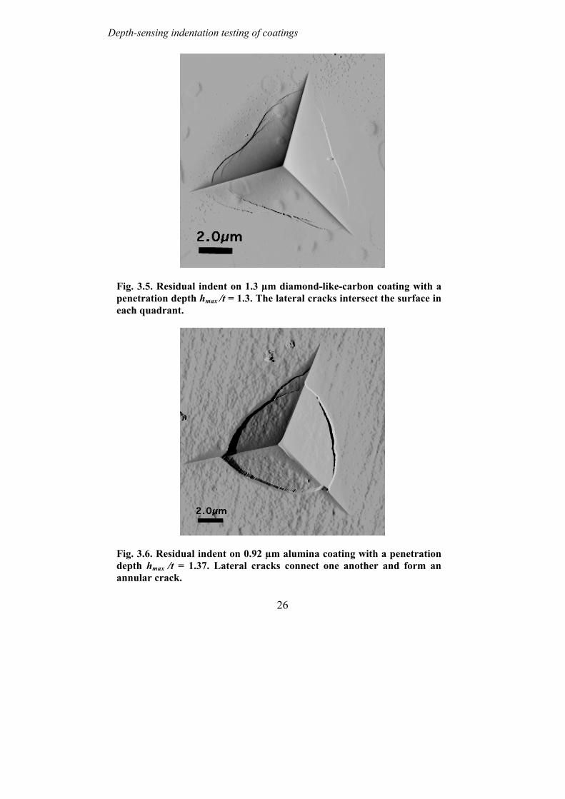
Depth-sensing indentation testing of coatings
Fig. 3.5. Residual indent on 1.3 µm diamond-like-carbon coating with a penetration depth hmax /t = 1.3. The lateral cracks intersect the surface in each quadrant.
Fig. 3.6. Residual indent on 0.92 µm alumina coating with a penetration depth hmax /t = 1.37. Lateral cracks connect one another and form an annular crack.
26

Zhi-Hui Xu , Ph. D. Thesis, MSE, KTH, 2004
Fig. 3.7. Residual indent on 0.92 µm alumina coating with a penetration depth hmax /t = 2.6. Delamination occurs in the centre of the indent.
A typical crack initiation and propagation process of hard coatings during indentation can be illustrated by the atomic force microscope images of residual indents shown in Figs. 3.4 – 3.7 (Xu and Rowcliffe 2002c). The crack will first initiate in the middle of one of the three quadrants, which is separated by the plastically deformed grooves induced by the edges of the Berkovich indenter, and then propagates to the corners of the indent while still limited within the quadrant (see Fig. 3.4). Meanwhile, cracks may also initiate and propagate at the other two quadrants and form a partially developed lateral crack (see Fig. 3.5). Further penetration will connect the three lateral cracks in different quadrants and form an annular crack (see Fig. 3.6). When the penetration depth is large enough, more annular cracks are developed and form a growth ring of cracks with the delamination in the centre (see Fig. 3.7).
27

Depth-sensing indentation testing of coatings
28

Zhi-Hui Xu , Ph. D. Thesis, MSE, KTH, 2004
4 Indentation of WC-Co gradient materials WC-Co cemented carbides is a widely used wear resistant composite for cutting tool applications. With hard WC particles imbedded in a soft Co matrix, WC-Co cemented carbides normally show high hardness and strength combined with a satisfactory toughness. To further improve the wear performance of cutting tools and to adapt to the increasing applications of mechanically held inserts, harder coating is often applied on much tougher cemented carbides or other substrates using various coating techniques (Brookes 1987). To join the coating and the substrate a gradual change of the material composition and properties from the coating to the substrate is usually preferred to avert the local stress concentration caused by an abrupt transition. By using a gradient of mechanical properties, it is possible to mitigate the stress concentration, enhance the adhesion of surface coating, and ‘tailor’ the mechanical properties according to the application requirements (Suresh and Mortensen 1997, Schulz et al. 2003).
4.1 Models for mechanical properties of WC-Co cemented carbides.
The mechanical properties of WC-Co cemented carbides can be directly related to the microstructural parameters, such as, the volume fraction of Co phase, the mean free path of the Co phase or the WC particle size, and the contiguity of the WC particles. Once these microstructural parameters are known, the mechanical properties of cemented carbides namely hardness and elastic modulus may be predicted using different models available in the literature. Several models are available for the calculation of the hardness of cemented carbides (Charmant et al. 1973, Lee and Gurland 1978, Makhele-Lekala et al. 2001, Engqvist et al. 2002). Among them the most widely accepted model is the one proposed by Lee and Gurland (1978). By analysing the plastic limit of the effects of the continuous carbide and binder phase, Lee and Gurland found that the yield stress of WC-Co cemented carbide can be related to the yield stresses of WC and Co phase by
σCC = σWCVWCC +σ Co 1 − VWCC( ) (4.1)
29

Indentation testing of WC-Co gradient materials
where σCC , σWC , σCo are the yield stress of the cemented carbides, the WC particle, and the Co phase, respectively. VWC is the volume fraction of WC particles. C is the contiguity of the carbides and defined as the fraction of the total surface area of a carbide particle shared by the nearby carbide particles. Assuming that the ratios of hardness to the yield stress of the WC-Co composite, of the carbide, and of the Co phase are equal to 3, Lee and Gurland developed the hardness model of WC-Co cemented carbides by replacing the yield stresses in Eq. (4.1) with the hardnesses and the hardness of WC-Co cemented carbides is given by
HCC = HWCVWCC + HCo 1 − VWCC( ) (4.2) where HCC , HWC , HCo are the hardness of the cemented carbides, the WC particles, and the cobalt matrix, respectively. The in situ hardnesses of the carbide and the cobalt matrix are assumed to obey a Hall-Petch relation, that is,
HWC = 13.54 +7.159
d (4.3)
HCo = 2.979 +3.936
λ (4.4)
where d is the carbide particle size and λ is the mean free path of the binder phase. The hardness here is in the unit of GPa. d and λ are in the unit of µm and the relationship between d and λ is given by
λ = dVCo
1 − VCo( )1 − C( ) (4.5)
where VCo is the volume fraction of the Co phase and VCo + VWC = 1.
One of the disadvantages of the Lee and Gurland model is that the measurement of the contiguity of carbides is often tedious. Moreover, there are still arguments regarding the existence of continuous carbide skeleton (Gurland and Norton 1952, Grathwohl and Warren 1974, Sharma et al. 1980, Friederich 1983, Andren et al. 1993, Engqvist et al. 1998). Hardness models which do not explicitly include the carbide contiguity are also available in the literature. For example, Mekhele-Lekala et al. (2001) proposed an empirical model based on theoretical analysis of the dislocation pileup in cemented carbides. According to their model, hardness of cemented carbides is given by
HCC = 1.735 + 7.513d0.251λ−0.497 (4.6)
30
Zhi-Hui Xu , Ph. D. Thesis, MSE, KTH, 2004
Engqvist et al. (2001) also proposed another empirical model based on the assumption that very thin binder layers confined between hard phase grains are forced to behave mechanically as the confining materials. Their model gives an exponential relationship between the hardness of cemented carbides and the mean free path of binder phase, that is,
HCC = HWC − HCo( )e−λk + HCo (4.7)
where k is equal to 0.35 µm, which is the best fit of the experimental data, HCo equals 8.085 GPa, and
HWC = 6.791+26.2642.1+ d
(4.8)
λ =dV
1 −Co
VCo
(4.9)
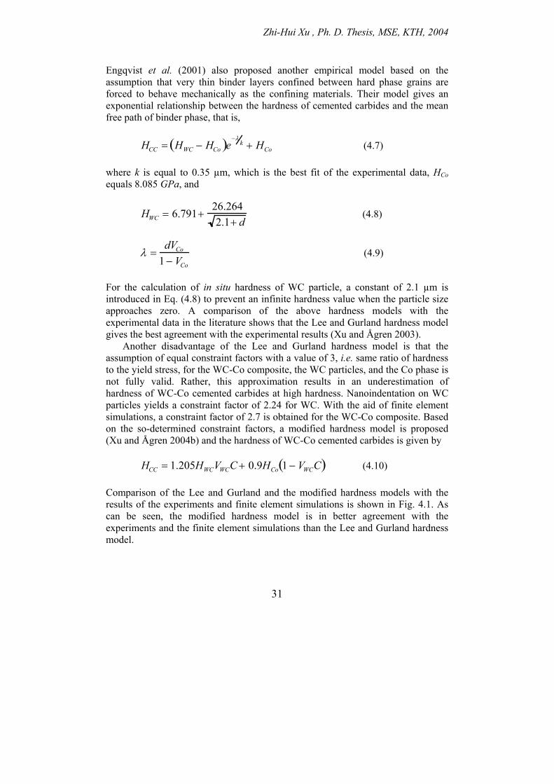
For the calculation of in situ hardness of WC particle, a constant of 2.1 µm is introduced in Eq. (4.8) to prevent an infinite hardness value when the particle size approaches zero. A comparison of the above hardness models with the experimental data in the literature shows that the Lee and Gurland hardness model gives the best agreement with the experimental results (Xu and Ågren 2003).
Another disadvantage of the Lee and Gurland hardness model is that the assumption of equal constraint factors with a value of 3, i.e. same ratio of hardness to the yield stress, for the WC-Co composite, the WC particles, and the Co phase is not fully valid. Rather, this approximation results in an underestimation of hardness of WC-Co cemented carbides at high hardness. Nanoindentation on WC particles yields a constraint factor of 2.24 for WC. With the aid of finite element simulations, a constraint factor of 2.7 is obtained for the WC-Co composite. Based on the so-determined constraint factors, a modified hardness model is proposed (Xu and Ågren 2004b) and the hardness of WC-Co cemented carbides is given by
HCC = 1.205HWCVWCC + 0.9HCo 1 − VWCC( ) (4.10) Comparison of the Lee and Gurland and the modified hardness models with the results of the experiments and finite element simulations is shown in Fig. 4.1. As can be seen, the modified hardness model is in better agreement with the experiments and the finite element simulations than the Lee and Gurland hardness model.
31

Indentation testing of WC-Co gradient materials
(a)
(b)
Fig. 4.1. Comparison of the Lee and Gurland (Eq.(4.2)) and the modified hardness models (Eq.(4.10)) with the results of experiments and finite element simulations. (a) experiments; (b) finite element simulations.
32

Zhi-Hui Xu , Ph. D. Thesis, MSE, KTH, 2004
Fig. 4.2. Bounds for elastic modulus of WC-Co cemented carbides. E1*
and E2* denote the lower and upper bounds (Hashin and Shtrikman
1963).
The elastic modulus of two-phase materials can be related to the elastic modulus and the volume fraction of each individual phase. Models have been developed to find the upper and lower bounds of the effective elastic modulus of multiphase material (Paul 1960, Hashin and Shtrikman 1963). For WC-Co cemented carbides, it has been shown that the Hashin and Shtrikman model gives much closer bounds compared with the Paul model and the lower bound of the Hashin and Shtrikman model agrees well with the experimental data (see Fig. 4.2). A recent experimental measurement of the elastic modulus of WC-Co cemented carbides using resonant ultrasound spectroscopy and impulse excitation also shows a very good agreement with the prediction of the Hashin and Shtrikman model
33

Indentation testing of WC-Co gradient materials
(Koopman et al. 2002). The lower bound of the effective bulk and shear moduli of WC-Co cemented carbides is given by
KCC = KCo +VWC
1KWC − KCo
+ 3VCo
3KCo + 4GCo
(4.11)
GCC = GCo +VWC
1GWC − GCo
+6 KCo + 2GCo( )VCo
5GCo 3KCo + 4GCo( )
(4.12)
where KCC, KCo, and KWC are the bulk moduli of the cemented carbides, Co, and WC, respectively and GCC, GCo, and GWC the corresponding shear moduli. The relationship between the elastic modulus and the bulk and shear moduli is defined by
K =E
3 1− 2( ν) (4.13)
G =E
2 1+( ν) (4.14)
combination of Eqs.(4.13) and (4.14) yields
GKKGE+
=39
(4.15)
An upper bound of the effective elastic modulus of WC-Co cemented carbides can also be obtained by exchanging the subscripts of WC and Co in both Eqs. (4.11) and (4.12), i.e. replacing the subscript WC with Co and vice verse.
4.2 Depth sensing indentation of WC-Co gradient coatings. With the fast development of coating techniques, harder coatings such as diamond, c-BN, TiN, TiC, SiC, or Al2O3 are often used to further improve the wear performance of cutting tools (Fella et al. 1988, Murakawa and Watanabe 1990, Shibuki et al. 1994, Prchlik et al. 2001, Lima et al. 2002, Costa and Camargo 2003, Ducros et al. 2003). In the design and manufacture of coatings, a gradual change of composition and mechanical properties, i.e. building a gradient coating,
34

Zhi-Hui Xu , Ph. D. Thesis, MSE, KTH, 2004
is preferred in order to increase the wear resistance, mitigate the stress concentration, enhance the adhesion of the coating, and ‘tailor’ the mechanical properties according to the applications (Neubrand and Rodel 1997, Suresh and Mortensen 1997, Suresh 2001, Schulz et al. 2003). The gradient coatings can be produced through either different multi-layer deposition techniques, such as, physical vapour deposition and chemical vapour deposition (Fella et al. 1988, Prchlik et al., 2001, Schulz et al. 2003) or powder metallurgy techniques, such as, gradient sintering (Frykholm et al. 2001, 2003).
Depth sensing indentation is one of the most important techniques for measuring the mechanical properties of coatings. Extensive research has been made to investigate indentations of films and coatings (Bhattacharya and Nix 1988, Wang and Bargert 1993, Sun et al. 1995, Cai and Bargert 1995, Lichinchi et al. 1998, Chen and Vlassak 2001, Xu and Rowcliffe 2004), elastically (Suresh et al. 1997, Giannakopoulos and Suresh 1997, Giannakopoulos and Pallot 2000) and plastically (Giannakopoulos 2002) graded bulk materials, and gradient coatings (Stephens et al. 2000, Xu and Ågren 2003) using finite element methods. By applying appropriate gradient in elastic and/or plastic properties, the resistance to contact damage can also be significantly enhanced.
Fig. 4.3. Composite hardness variation with penetration depth of WC-Co gradient coatings with different Co content gradients. g1, g2, and g3 denote the Co content gradients with 5% Co on the coating surface and 13%, 21%, and 29% Co in the substrate, respectively. d0.5, d2.5, and d5.0 denote the WC particle sizes of 0.5 µm, 2.5 µm, and 5.0 µm, respectively.
35
Indentation testing of WC-Co gradient materials
36
For coatings with a gradient in composition and properties, the variation of the mechanical properties depends on the existing gradient and the deformation extent of the gradient coatings, which can be predicted through finite element simulations. An example of the composite hardness variation of WC-Co coatings with different Co content gradients is shown in Fig. 4.3 (Xu and Ågren 2003). As can be seen, the composite hardness of the WC-Co gradient coatings depends on the Co content gradient and WC particle size and decreases with increasing penetration depth. This decrease of the composite hardness is found to be proportional to the Co content gradient while almost independent of the WC particle size.

Zhi-Hui Xu , Ph. D. Thesis, MSE, KTH, 2004
37
5 Summary of the appended papers Paper I. Method to determine the plastic properties of bulk materials by
nanoindentation In this paper, the indentation of elastic-plastic strain-hardening material with a conical indenter was investigated using the finite-element method. The influence of the ratio of the elastic recovered depth he to the maximum penetration depth hmax on the deformation behaviour of the material and its relationship with the material parameters σy /E and strain hardening exponent n were analysed. The finite element results were compared with the results of Berkovich indentations on single-crystal aluminium, single-crystal tungsten, nickel, lead, fused silica, and BK7 glass. It is found that he /hmax can be directly related to the elastic-plastic properties σy /E and n of a material, which determine the deformation behaviour of materials. The pile-up and sinking-in behaviour of the material during indentation is controlled by both strain hardening and he /hmax. No pile-up occurs for materials with n > 0.3; for materials with n < 0.3, the critical value of he /hmax for pile-up and sinking-in is 0.12. The hardness of a material measured by indentation is a function of the stress at about 10% plastic strain for both soft and hard materials. Direct comparison of finite-element results with experimental indentations shows good agreement. Based on the analysis, a method that can be used to estimate the plastic properties of bulk materials is proposed.
The present author performed the work and wrote the paper, supervised by David Rowcliffe.
Paper II. An analysis of piling-up or sinking-in behaviour of elastic plastic
materials under sharp indentation. This paper presents a further analysis of the piling-up or sinking-in behaviour of elastic-plastic strain-hardening materials under sharp indentation using finite element simulations. An empirical model is proposed to relate the contact area to the material parameter E /σy and the experimental parameter he /hmax. It is found that materials with E /σy < 89.07 in the limit of vanishing friction and E /σy < 150.7

Summaries of the appended papers
38
for a fiction coefficient µ = 0.2 may show only sinking-in. Other materials may show either piling-up or sinking-in depending on he /hmax ratio or strain-hardening exponent. There is no universal he /hmax ratio that can be used to predict the piling-up or sinking-in behaviour of materials. Rather the critical he /hmax ratio or strain-hardening exponent for no piling-up or sinking-in is a function of E /σy . Piling-up or sinking-in behaviour of materials is found closely related to the fully plastic deformation. Influence of friction on the mount of piling-up or sinking-in has also been considered in this study.
The present author performed the work and wrote the paper, supervised by John Ågren.
Paper III. Deriving mechanical properties of soft coatings using nanoindenation: an
application of mechanism-based strain gradient plasticity. In this paper, a dislocation model based on mechanism-based strain gradient theory has been used to analyse the indentation process on soft coating systems. It is shown that the indentation process can be divided into two stages, according to the critical penetration depth for every soft coating. For penetration depth smaller than the critical penetration depth, the soft coating behaves the same as the bulk material and the deformation behaviour can be well defined by the dislocation model, while for penetration depths larger than the critical depth, the influence of the substrate is triggered and deviation from the dislocation model occurs. The ratio of the critical penetration depth to the coating thickness depends on the coating types, but not on the coating thickness. The ratio is approximately 0.2 for Au/Ni coatings and approximately 0.4 for Al/BK7 coatings. The coating-only mechanical properties can be determined from the indentation data with penetration depth smaller than the critical value using the mechanism-based strain gradient theory.
The present author performed the work and wrote the paper, supervised by David Rowcliffe.
Paper IV. Nanoindentation on diamond-like-carbon and alumina coatings. A linear relationship of the square of indentation hardness and the inverse of penetration depth predicted by the mechanism-based strain gradient theory has been used to derive the coating-only hardness of the hard coatings and the critical penetration depth, where the influence of the soft substrate comes in. The ratio of the critical penetration depth to the coating thickness is approximately 0.2 for both diamond-like-carbon and alumina coatings and almost independent of the coating

Zhi-Hui Xu , Ph. D. Thesis, MSE, KTH, 2004
39
thickness. Observation of residual indents on both diamond-like-carbon and alumina coatings by atomic force microscopy reveals that plastic deformation occurs in the hard coatings when the penetration depth is smaller than the critical depth. With further penetration, partial lateral cracks first initiate in the middle of the quadrants between the radial plastically deformed grooves induced by the indenter edges, then propagate to the corner of the indent and connect with one another to form an annular crack. With the increase of the penetration depth more annular cracks are created and form a growth ring of cracks. A significant delamination may occur at the centre of the indent for a deep enough penetration.
The present author performed the work and wrote the paper, supervised by David Rowcliffe.
Paper V. Finite element analysis of substrate effects on indentation behaviour of
thin films. In this paper, the substrate effects on indentation behaviour of thin films are analysed using finite element method. There is no universal critical penetration depth beyond which the substrate effects come in. The critical penetration depth depends on the combination of the film and the substrate and more sensitive to differences in the elastic properties than in the plastic properties of the film/substrate system. The finite element simulation results of the substrate on the elastic modulus and the hardness of the film/substrate system have also been compared with the empirical models of Doerner and Bhattacharya, respectively.
The present author performed the work and wrote the paper, supervised by David Rowcliffe.
Paper VI. A modified hardness model for WC-Co cemented carbides. In this paper, the constraint factors of WC particles and WC-Co cemented carbides are determined using nanoindentation and finite element simulation. A modified hardness model has been proposed based on the determined constraint factors. Comparisons of the modified hardness model and Lee and Gurland hardness model with the results of finite element simulations and the experiments show that the modified model gives better prediction of the hardness of WC-Co cemented carbides.
The present author performed the work and wrote the paper, supervised by John Ågren.

Summaries of the appended papers
40
Paper VII. Effect of cobalt content gradients on hardness of WC-Co coatings:
Finite element simulations. In this paper, the existing empirical models for the mechanical properties of cemented carbides are evaluated and implemented into finite element modelling using ABAQUS. The finite element models are calibrated with the experimental data of cemented carbides. Finite element simulations of sharp indentations on WC-Co gradient coatings are made to investigate the influence of the mass cobalt content gradients on the hardness of the gradient coatings. Three cobalt content gradients with 5% Co on the coating surface and 13%, 21%, and 29% Co in the substrates, respectively have been considered with varied WC particle sizes and indentation penetration depths. It is shown that the composite hardness of the WC-Co gradient coatings depends on the cobalt content gradient and the WC particle size and decreases with increasing penetration depth. This decrease of the composite hardness is proportional to the cobalt content gradient while almost independent of the WC particle size.
The present author performed the work and wrote the paper, supervised by John Ågren.

Zhi-Hui Xu , Ph. D. Thesis, MSE, KTH, 2004
41
6 Conclusions and future work
6.1 Concluding remarks The present research has focused on the mechanical characterisation of bulk materials, thin films and coatings, gradient materials, and composites with depth-sensing indentation. The indentation deformation behaviour of materials and its influence on the measured mechanical properties have been studied through both depth-sensing indentation test and finite element simulations. The results presented in this thesis would be useful not only for acquiring the knowledge about deformation behaviour of materials under indentation but also for determining the mechanical properties using depth-sensing indentation technique. The finite element model developed for gradient coatings can be used as a helpful tool for the design and evaluation of gradient coatings.
For deriving the plastic properties of materials through depth-sensing indentation, it is important to know the relation between indentation hardness and the mechanical properties of materials. In the present thesis a general relationship between the hardness and the indentation representative stress, which applies to both soft and hard materials, has been obtained through finite element simulations. This new relationship has been successfully used, instead of Tabor’s relationship that is valid only for soft metals, to estimate the yield stress of hard WC phase in WC-Co cemented carbides.
The real contact area of indentation is a crucial parameter in the analysis of mechanical properties by depth-sensing indentation. Surface deformation of materials around the indenter often plays an important role in the accurate determination of the contact area using the available analysing methods, e.g. Oliver and Pharr method, which cannot account for the piling-up behaviour of materials. It has been shown that the piling-up or sinking-in behaviour of elastic-plastic strain-hardening materials under sharp indentation is determined by the E/σy ratio, the strain hardening exponent or the he /hmax ratio, and the contact friction. An empirical model, which relates the contact area of indentation to the E/σy ratio and the he /hmax ratio, can be used to predict the piling-up or sinking-in behaviour of materials. The existence of friction, which enhances the sinking-in tendency of materials, also influences the determination of the contact area.

Conclusions and future work
42
Determination of coating-only properties requires elimination of the substrate effects. This could be done in two ways, i.e., either making an indentation shallower than the critical penetration depth beyond which the substrate effects become important or using analytic or empirical models. Nanoindentation test of different coatings shows that the ratio of the critical penetration depth to coating thickness depends only on the coating/substrate types but not on the coating thickness. Finite element analysis further reveals that the critical penetration depth is more sensitive to differences in elastic properties than in plastic properties of the coating/substrate system. This implies that it would be hard to avoid the substrate effects when indentation is made on a coating/substrate system with large difference in elastic moduli. A worst case would be that the coating is much stiffer than the substrate, which is a common situation for most tribological applications.
The deformation behaviour of coatings depends on the coating type. For soft coating, the plastic deformation is usually confined within the soft coating and extensive piling-up often occurs due to the truncation effect of the hard substrate. For hard coating, the deformation behaviour may be dominated by either the plastic deformation in the hard coating when the penetration depth is less than the critical penetration depth or the cracking of hard coating and the plastic deformation in the soft substrate when the penetration depth is larger than the critical penetration depth.
By determining the constraint factors of WC phase and WC-Co cemented carbides through nanoindentation and finite element simulations, a modified hardness model (Eq. (4.10)) has been proposed to improve the estimation of the hardness of WC-Co cemented carbides.
The mechanical properties of gradient coatings would be expected to vary with the existing gradient and the deformation extent. As a first step, finite element model has been built to investigate the influence of the Co content on the hardness of WC-Co gradient coatings. It is shown that the composite hardness of the WC-Co gradient coatings depends on the Co content gradient and the WC particle size and decreases with increasing penetration depth. This decrease of the composite hardness is proportional to the Co content gradient while almost independent of the WC particle size.
6.2 Suggestions for future work Evidently, the introduction of gradients in the Co content and the WC particle size creates not only a mechanical property gradient but also a residual stress gradient inside the coating owing to the mismatch of thermal expansion coefficients and the mechanical properties. This residual stress gradient will also influence the mechanical properties of the gradient coatings and play an important role in the failure of the gradient coatings during applications. Thus the residual stress gradient should be included into the finite element modelling and the effects of the

Zhi-Hui Xu , Ph. D. Thesis, MSE, KTH, 2004
43
residual stress gradient on the mechanical properties and the possible failures of gradient coatings should be investigated.
Common failures for hard coatings are the surface cracking and the debonding and delamination of the coating from the substrate. These failures are closely related to the critical stresses, such as, the tensile stress at the surface, which causes the surface cracking, and the shear stress and the out-plane tensile stress at the interface, which results in the debonding and delamination. By introducing different types of gradients in mechanical properties, these critical stresses may be mitigated and the resistance to failure may be enhanced. For examples, controlled gradients in elastic properties at the contact surface of graded materials is found highly resistant to Hertzian contact damage (Suresh et al. 1999, Pender et al. 2001a, 2001b). Therefore a future research will be to investigate the variation of these critical stresses with the gradients in Co content and WC particles size and the deformation extent through finite element simulations. On this basis, an optimum gradient for WC-Co gradient coatings may be determined.
In the real machinery situation, the stresses endured by the cutting insert may be different from the stresses introduced by sharp indentation test used in this study. A future research should be to perform finite element simulations with the stress states closer to the real situation during cutting or drilling so that a more accurate evaluation of the failure resistant ability of the gradient coatings could be achieved.

Conclusions and future work
44
Zhi-Hui Xu , Ph. D. Thesis, MSE, KTH, 2004
45
Acknowledgements I would like to thank all colleagues and friends who have helped and encouraged me during the course of this work. I am especially indebted to the following people who have been directly involved in my work:
My supervisor, Professor John Ågren, for giving me the opportunity to continue this thesis work and for his encouragement, valuable discussions, and excellent guidance. My previous supervisor, Professor David Rowcliffe, for introducing me to the stimulating research world of nanoindentation and for all the encouragement and illuminating discussions. Professor Per-Lennart Larsson, for his kind help and valuable discussions and Professor Kjell Pettersson for his administrative advice and help.
All the partners in INDICOAT project for the knowledgeable communication and the valuable discussions, especially Dr. Nigel Jennett (NPL), Dr. Neil McCartney (NPL), Dr. Thomas Chuduba (TUC), and Dr. Jan Meneve (VITO), for their helps and discussions. All the partners in Gradient Materials group at BRIIE, especially Professor Mats Nygren (SU), Associate Professor Gunnar Westin (UU), Dr. Jeanette Persson (Sandvik Coromant), Dr. Niklas Ahlen (Seco Tools), Dr. Kjell Jansson (SU), and Dr. Åsa Ekstrand (UU), for their help and collaboration. Dr. Kaiyang Zeng (IMRE), for all the helps and valuable discussions at the beginning of my work at KTH.
Other colleagues at the department, Dr. Bengt Selling, for sharing his life experience and extensive knowledge in materials. Associate Professor Stefan Jonsson and Dr. Lars Höglund, for maintaining the ABAQUS license. Anders Borggren and Jan Bång, for the kind help with computer problems. Henrik Strandlund, for the help in Matlab programming. Kwadwo Kese, Cecelia Eriksson, and Mats Eskner, for all the discussions on indentation. Wen Li Long, Hans Bergqvist, P-O Söderholm, and Henry Waldell, for various technical assistance.
Last but not the least, my wife, Hongyi, and my daughter, Jiaqian, for their patient, support, care, and love. This work has been financially supported by EC standards, Measurements, and Testing Programme under the Contract Number SMT4-CT98-2249 and by The Swedish Agency for Innovation Systems (VINNOVA) and the following companies: Atlas Copco Sedoroc AB, Erasteel Kloster AB, Höganäs AB, Sandvik Coromant AB, and Seco Tools AB through The Brinell Centre-Inorganic Interfacial Engineering (BRIIE).

46
Zhi-Hui Xu , Ph. D. Thesis, MSE, KTH, 2004
47
Bibliography Ahn, J.-H., and Kwon, D., 2001, J. Mater. Res., 16, 3170. Alcala, J., Giannakopoulos, A.E., and Suresh, S., 1998, J. Mater. Res., 13, 1390. Andren, H.-O., Rolander, U., and Lindahl, P., 1993, Int. J. Refract. Met. Hard
Mater., 12, 107. Atkins, A.G., and Tabor, D., 1965, J. Mech. Phys. Solids., 13, 149. Bhattacharya, A.K., and Nix, W.D., 1988, Int. J. Solids Structures, 24, 1287; 1991,
Int. J. Solids Structures, 27. 1047. Biwa, S., and Storåkers, B., 1995, J. Mech. Phys. Solids, 43, 1303. Bolshakov, A., and Pharr, G.M., 1998, J. Mater. Res., 13, 1049. Brookes, K.J.A., 1987, World Directory and Handbook of Hardmetals (4th edition),
(International Carbide Data, UK), 50. Bucaille, J.L., Stauss, S., Felder, E., and Michler, J., 2003, Acta Mater., 51, 1663. Bull, S.J., Page, T.F., and Yoffe, E.H., 1989, Phil. Mag. Lett., 59, 282. Burnett, P.J., and Rickerby, D.S., 1987, Thin Solid Films., 148, 41. Bückle, H., 1973, The Science of Hardness Testing and Its Research Applications,
edited by Westbrook, J.H., and Conrad, H., (ASM Metals Park, Ohio), 453. Cai, X., and Bargert, H., 1995, Thin Solid Films, 264, 59. Chen, X., and Vlassak, J.J., 2001, J. Mater. Res., 16, 2974. Cheng, Y.-T., and Cheng, C.-M., 1998a, J. Appl. Phys., 84, 1284; 1998b, J. Mater.
Res., 13, 1059; 1998c, Phil. Mag. Lett., 78, 115; 1999, Int. J. Solids Sturctures, 36, 1231.
Chermant, J.L., Deschanvres, A., Hautiers, G., Iost, A., and Manier, G., 1973, Phys. Stat. Sol. (a), 15, K149.
Chicot, D., and Lesage, J., 1995, Thin Solid Films, 254, 123. Chollacoop, N., Dao, M., and Suresh, S., 2003, Acta Mater., 51. 3713. Costa, A.K., and Camargo, S.S., 2003, Surf. Coat. Technol., 163-164, 176. Dao, M., Chollacoop, N., Van Vliet, K.J., Venkatesh, T.A., and Suresh, S., 2001,
Acta Mater., 49, 3899. Doerner, M.F., and Nix, W.D., 1986, J. Mater. Res., 1, 601. Ducros, C., Benevent, V., and Sanchette, F., 2003, Surf. Coat. Technol., 163-164,
681. Engqvist, H., Botton, G.A., Axen, N., and Hogmark, S., 1998, Int. J. Refract. Met.
Hard Mater., 16, 309. Engqvist, H., Jacobson, S., and Axen, N., 2002, Wear, 252, 384. Fella, R., Holleck, H., and Schulz, H., 1988, Surf. Coat. Technol., 36, 257. Field, J.S., and Swain, M.V., 1993, J. Mater. Res., 8, 297; 1995. J. Mater. Res., 10,
101. Field, J.S., Swain, M.V., and Dukino, R.D., 2003, J. Mater. Res., 18, 1412.

Bibliography
48
Friederich, K.M., 1983, Met. Sci., 17, 456. Frykholm, R., Ekroth, M., Jansson, B., Andren, H.-O., and Ågren, J., 2001, Int. J.
Refract. Met. Hard Mater., 19, 527. Frykholm, R., Ekroth, M., Jansson, B., Ågren, J., and Andren, H.-O., 2003, Acta
Mater., 51, 1115. Gao, H.J., Chiu, C.-H., and Lee, J., 1992, Int. J. Solids Structures, 29, 2471. Giannakopoulos, A.E., 2002, Int. J. Solids Structures, 39, 2495. Giannakopoulos, A.E., Larsson, P.-L., and Vestergaard, R., 1994, Int. J. Solids
Structures, 31, 2679. Giannakopoulos, A.E., and Pallot, P., 2000, J. Mech. Phys. Solids, 48, 1597. Giannakopoulos, A.E., and Suresh, S., 1997, Int. J. Solids Structures, 34, 2393;
1999, Scripta Mater., 40, 1191. Grathwohl, G., and Warren, R., 1974, Mater. Sci. Eng., 14, 55. Gurland, J., and Norton, J.T., 1952, Trans. AIME J. Met., 4, 1051. Hainsworth, S.V., Chandler, T.F., and Page, T.F., 1995, J. Mater. Res., 10, 1987. Hashin, Z., and Shtrikman, S., 1963, J. Mech. Phys. Solids, 11, 127. Hay, J.C., Bolshakov, A., and Pharr, G.M., 1999, J. Mater. Res., 14, 2296. Herrmann, K., Jennett, N.M., Wegener, W., Meneve, J., Hasche, K., and Seemann,
R., 2000, Thin Solid Films, 377-378, 394. Hertz, H.,1882, J. Math., 92, 156. Hill, R., 1950, The Mathematical Theory of Plasticity, (Oxford: Clarendon). Johnson, K.L., 1985, Contact Mechanics, (Cambridge University Press). Jonsson, B., and Hogmark, S., 1984, Thin Solid Films, 114, 247. King, R.B., 1987, Int. J. Solids Structures, 23, 1657. Koopman, M., Chawla, K.K., Coffin, C., Patterson, B.R., Deng, X., Patel, B.V.,
Fang, Z., and Lockwood, G., 2002, Adv. Eng. Mater., 4, 37. Korsunsky, A.M., McGurk, M.R., Bull, S.J., and Page, T.F., 1998, Surf. Coat.
Technol., 99, 171. Larsson, P.-L., 2001, Inter. J. Mech. Sci., 43, 895. Larsson, P.-L., Giannakopoulos, A.E., Söderlund, E., Rowcliffe, D.J., and
Vestergaard, R., 1996, Int. J. Solids Structures, 33, 221. Laursen, T.A., and Simo, J.C., 1992, J. Mater. Res., 7, 618. Lawn, B.R., Evans, A.G., and Marshall, D.B., 1980, J. Am. Ceram. Soc., 63, 574. Lee, H.C., and Gurland, J., 1978, Mater. Sci. and Eng., 33, 125. Li, H., and Bradt, R.C., 1993, J. Mater. Sci., 28, 917. Lichinchi, M., Lenardi, C., Haupt, J., and Vitali, R., 1998, Thin Solid Films, 312,
240. Lima, R.S., Karthikeyan, J., Kay C.M., Lindemann, J., and Bernt, C.C., 2002, Thin
Solid Films, 426, 129. Loubet, J.L., Georges, J.M., Marchesini, O., and Meille, G., 1984, J. Tribology,
106, 43. Lucas, B.N., and Oliver, W.C., 1999, Metall. Mater. Trans. 30A, 601. Makhele-Lekala, L., Luyckx, S., Nabarro, F.R.N., 2001, Int. J. Refract. Met. Hard
Mater., 19, 245.

Zhi-Hui Xu , Ph. D. Thesis, MSE, KTH, 2004
49
Mata, M., and Alcala, J., 2003, J. Mater. Res., 18, 1705. Mata, M., Anglada, M., and Alcala, J., 2002, J. Mater. Res., 17, 964. Mayo, M.J., and Nix, W.D., 1988, Acta Metall., 36, 2183. McColm, I.J.,1990, Ceramic Hardness (New York: Plenum). McGurk, M.R., and Page, T.F., 1999, J. Mater. Res., 14, 2283. Mencik, J., Munz, D., Quandt, E., Weppelmann, E.R., and Swain, M.V., 1997, J.
Mater. Res., 12, 2475. Mesarovic, S.D., and Fleck, N.A., 1999, Proc. R. Soc. Lond. A, 455, 2707. Mott, B.W., 1956, Micro-Indentation Hardness Testing (London: Butterworths). Murakawa, M., and Watanabe, S., 1990, Surf. Coat. Technol., 43-44, 145. Neubrand, A., and Rodel, J., 1997, Z. Metallkd., 88, 358. Nix, W.D., and Gao, H., 1998, J. Mech. Phys. Solids, 46, 411. Oliver, W.C., and Pharr, G.M., 1992, J. Mater. Res., 7, 1564. Page, T.F., Pharr, G.M., Hay, J.C., Oliver, W.C., Lucas, B.N., Herbert, E., and
Riester, L., 1998, Mat. Res. Soc. Symp. Proc., 522, 53. Paul, B., 1960, Trans. Metall. Soc. AIME, 218, 36. Pender, D.C., Padture, N.P., Giannakopoulos, A.E., and Suresh, S., 2001a, Acta
Mater., 49, 3255. Pender, D.C., Thompson, S.C., Padture, N.P., Giannakopoulos, A.E., and Suresh,
S., 2001b, Acta Mater., 49, 3263. Pethica, J.B., Hutchings, R., and Oliver, W.C., 1983, Phil. Mag. A, 48, 593. Pharr, G.M., 1998, Mater. Sci. Eng. A, 253, 151. Prchlik, L., Sampath, S., Gutleber, J., Bancke, G., and Ruff, A.W., 2001, Wear,
249, 1103. Raman, V., and Berriche, R., 1992, J. Mater. Res., 7, 627. Robach, J.S., Kramer, D.E., and Gerberich, W.W., 1998, Mat. Res. Soc. Symp.
Proc., 522, 133. Sakai, M., 2003, J. Mater. Res., 18, 1631. Sakai, M. and Nakano, Y., 2002, J. Mater. Res., 17, 2161. Sargent, P.M., 1986, Microindentation Techniques in Materials Science and
Engineering, edited by Blau, P.J., and Lawn, B.R., (ASTM, Philadelphia), 160. Schulz, U., Peters, M., Bach, Fr.-W., and Tegeder, G., 2003, Mater. Sci. Eng. A,
362, 61. Sharma, N.K., Ward, I.D., Fraser, H.L., and Williams, W.S., 1980, J. Am. Ceram.
Soc., 63, 3. Shibuki, K., Sasaki, K., Yagi, Y., Suzuki, T., and Ikuhara, Y., 1994, Surf. Coat.
Technol., 68, 369. Sneddon, I.N., 1946, Proc. Cam. Phil. Soc., 42, 29; 1948, Proc. Cam. Phil. Soc.,
44, 492; 1965, Int. J. Engng. Sci., 7, 1965. Stephens, L.S., Liu, Y., and Meletis, E.I., 2000, J. Tribology, 122, 381. Sun, Y., Bell, T., and Zheng, S., 1995, Thin Solid Films, 258, 198. Suresh, S., 2001, Science, 292, 5526. Suresh, S., Giannakopoulos, A.E., and Alcala, J., 1997, Acta Mater., 45, 1307. Suresh, S., and Mortensen, A., 1997, Int. Mater. Rev., 42, 85.

Bibliography
50
Suresh, S., Olsson, M., Giannakipoulos, A.E., Padture, N.P., and Jitcharoen, J., 1999, Acta Mater., 47, 3915.
Tabor, D., 1951, The Hardness of Metals (Oxford: Clarendon). Taljat, B., Zacharia, T., and Kosel, F., 1998, Int. J. Solids Structures., 35, 4411. Venkatesh, T.A., Van Vliet, K.J., Giannakopoulos, A.E., and Suresh, S., 2000,
Scripta Mater., 42, 833. Wang, H., and Bargert, H., 1993, Mater. Res. Soc. Symp. Proc., 308, 183. Xu, Z.-H., and Rowcliffe, D., 2002a, Philos. Mag. A, 82, 1893; 2002b, Surf. Coat.
Technol, 157, 231; 2002c, Surf. Coat. Technol., 161, 44; 2004, Thin Solid Films, 447-448, 399.
Xu, Z.-H., and Ågren, J., 2003, Euro PM2003 Conference Proceedings, Oct. 20-22, Valencia, Spain, 3. 135; 2004a, (Paper II, accepted for publication in Philos. Mag.); 2004b, (Paper VI, submitted to Mater. Sci. Eng. A).
Yurkov, A.L., Skvortsov, V.N., Buyanovsky, I.A., and Matvievsky, R.M., 1997, J. Mater. Sci. Lett., 16, 1370.
Zeng, K., and Chiu, C.-h., 2001, Acta Mater., 49, 3539.