mechanical cad for mechanical and aerospace engineers · pdf filemechanical cad for mechanical...
TRANSCRIPT

Mechanical CAD for Mechanical and Aerospace Engineers
Agenda
• ~Get acquainted with the basics of CAD software, as well as how to move models around using only the mouse and keyboard
• ~Learn how to use basic features, such as extrudes, extrude cuts, and fillets, as well as dimensioning

This tutorial is designed primarily for Mechanical and Aerospace Engineering students as an introduction to the design of machine elements with CAD programs. This tutorial will give a basic understanding of how to make machine elements and how to sketch and create basic machine elements with CAD programs.
This particular demonstration uses SolidWorks, but can be followed using Autodesk Inventor.
Autodesk Inventor can be found for free by registering at http://students.autodesk.com/

Before We Begin We need to be able to move the parts we create around to get a full
3D feel for them. This is done with the scroll button of the mouse.
Get to know your scroll button.
It is your friend. Scrolling the scroll button zooms pictures in and out. Clicking the scroll button allows us to rotate the part. Ctrl + clicking the scroll button pans the part around and Shift + clicking the scroll button rotates the part. (This is reversed for Inventor)
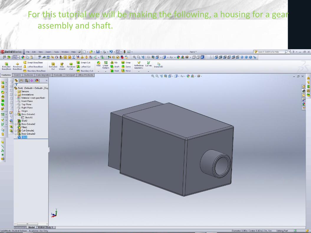
For this tutorial we will be making the following, a housing for a gear assembly and shaft.

We start by opening a new file. When a new file is opened the program asks what type of file is desired. Parts allow us to make single solid parts, which we will be doing for this tutorial. Assemblies allow us to put multiple parts together. Drawings allow us to make technical drawings of parts.
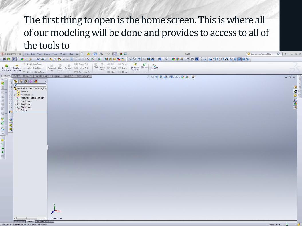
The first thing to open is the home screen. This is where all of our modeling will be done and provides to access to all of the tools to

Features are the basic 3D modeling of any part. First we will choose to do an extrude feature. The programs asks us to define a plane to sketch. All features have a sketch that they are based on. For this first part we will select the Front Plane to sketch on.
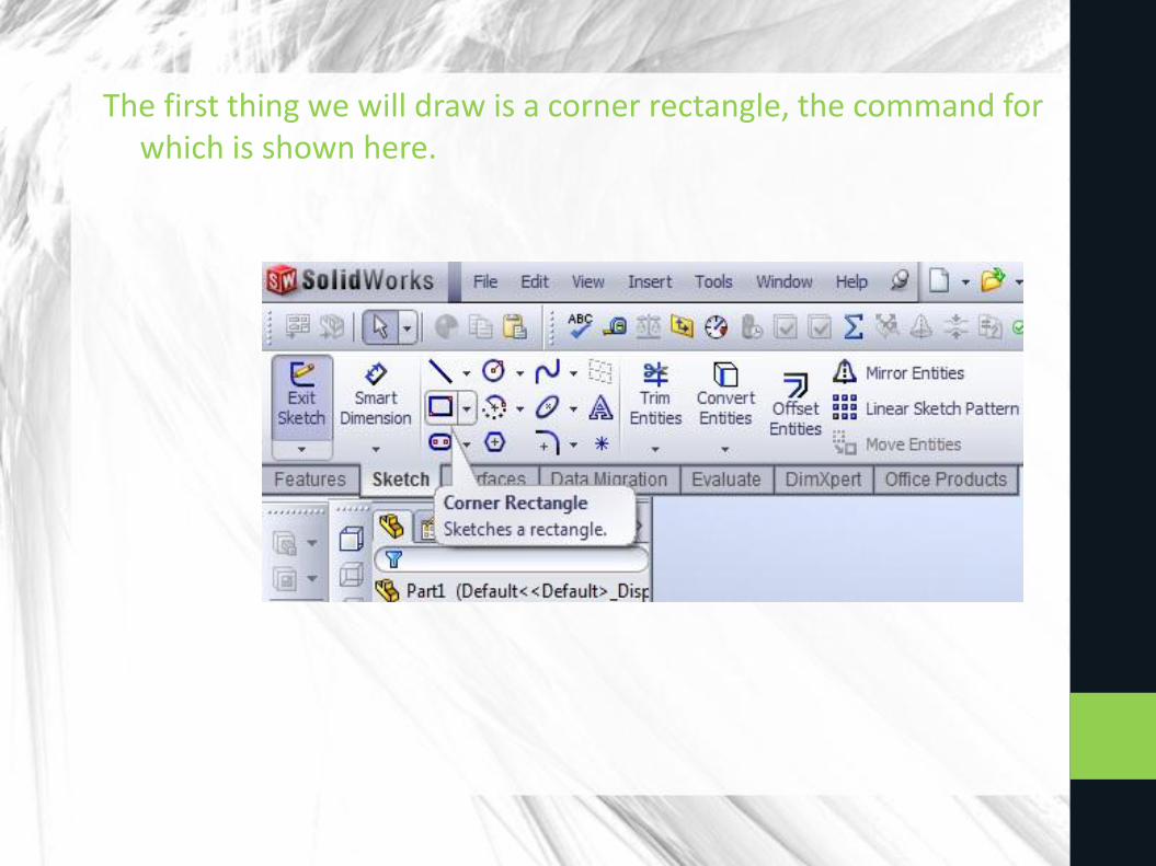
The first thing we will draw is a corner rectangle, the command for which is shown here.

We draw a rectangle from the origin. Notice how when we hover over the origin, the pointer clicks to it. This is called a snap and makes it easier to select points of interest, such as the origin. Dimension the rectangle as shown. In SolidWorks this can be done by choosing the position of the upper right point in the menu to the left.

We are now done and can click the 'Exit Sketch' button. The program now pulls us out into the extrude menu. An extrude pulls a shape a specified distance and makes a solid piece out of it. For this particular extrude let us use the menu to the left to set the distance to 4 in.

Our new solid feature should look as so.
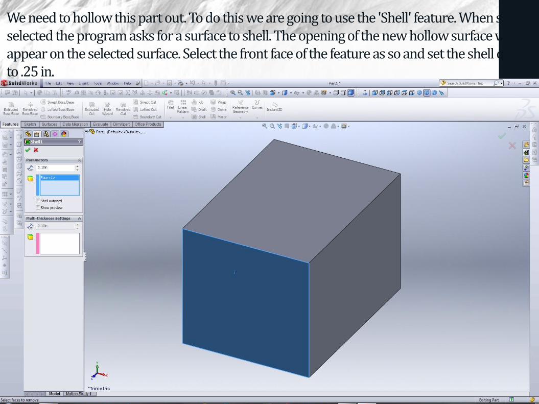
We need to hollow this part out. To do this we are going to use the 'Shell' feature. When shell is selected the program asks for a surface to shell. The opening of the new hollow surface will appear on the selected surface. Select the front face of the feature as so and set the shell depth to .25 in.

We should now have a hollow part. Now let us create the flange at the end of the piece. Sketches can be made on the principal planes as shown earlier, but also ON ANY FLAT SURFACE OF A PIECE. Click the surface shown and click sketch. This will open a new sketch on this surface.

It is convenient at this point to reorient our view to look at the piece head on. This can be done by rotating the piece with the scroll button as mentioned earlier, or by clicking on colored axis in the lower left corner of the drawing space.

Now draw the rectangle below. Notice how when we hover over the corners of the inner rectangle a snap appears, this makes making the following rectangle easy, by going from corner to corner of the inner rectangle.

We are now going to use a new sketch tool, and a powerful one at that, 'Offset Entities'. Click the Offset Entities button on the sketch toolbar

Select the rectangle just made. Notice how the tool makes a new rectangle, with a space between it and the original entity equal to the desired offset distance. Specify an offset distance and click the green check mark.

Now let us extrude this sketch. Notice how the extrusion selects only the profile between the two rectangles. Problem: We can't see the extrusion. To return to our original view angle let us select the orientations menu shown and return to an isotropic view and extrude the flange out 1 in.

Our new part should look something like this.
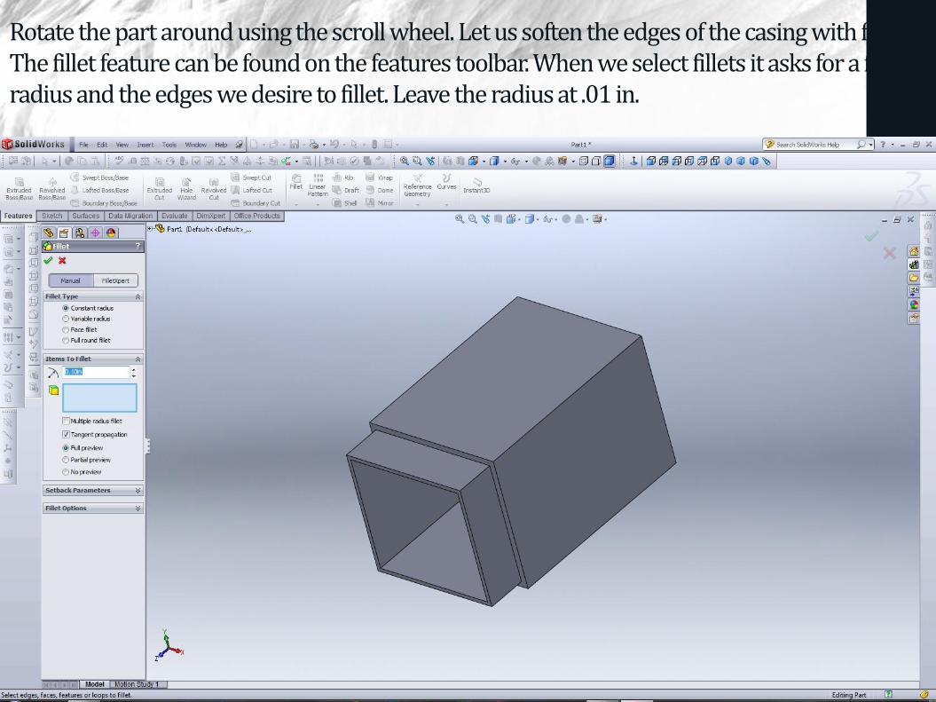
Rotate the part around using the scroll wheel. Let us soften the edges of the casing with fillets. The fillet feature can be found on the features toolbar. When we select fillets it asks for a fillet radius and the edges we desire to fillet. Leave the radius at .01 in.

After selecting all the edges hit the OK button. Our new filleted part should look something like this.

Let us now make the shaft end. First lets get a front view of the solid face. Select the face and go to the same view orientation menu as before, but this time select the 'Normal To' button. (Notice how there are many ways to get normal to a face)

We are going to have to draw a circle at the center of the face. The circle command is found on the sketch toolbar.

To get to the center of the face, hover over the midpoint of the above line and the right line. We should snap to these two lines and moving, snap to their intersection, the center of the face.

Draw a circle of arbitrary radius.

We can now modify our circle with a dimension. Dimensions are a powerful tool because they allow us to come back later and modify our drawing quickly and easily by simply changing the dimension.

Click on the dimension button, then click on the circle. Since a shaft is fitting through this hole it is important we get the dimensioning right. Change the diameter to 1 in.

We are now going to use a new feature, 'Extrude Cut' to make the hole. Extrude Cut works like extrude, except instead of making solid feature it destroys them in the path of the profile. Cuts can be controlled by making them go to surfaces. Select extrude to surface and select the inside surface, this will make a whole through the thickness.

Now that we have a hole, lets make the flange to hold the shaft. Select the same face and start a new sketch. Draw a circle larger than the hole, centered on it. Notice how when we hover over the center of the hole we can snap to its center. Next draw a circle of equal size to the hole.
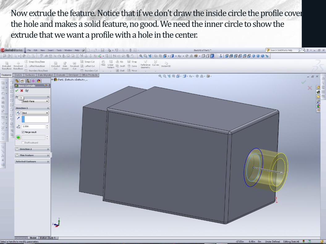
Now extrude the feature. Notice that if we don't draw the inside circle the profile covers the hole and makes a solid feature, no good. We need the inner circle to show the extrude that we want a profile with a hole in the center.
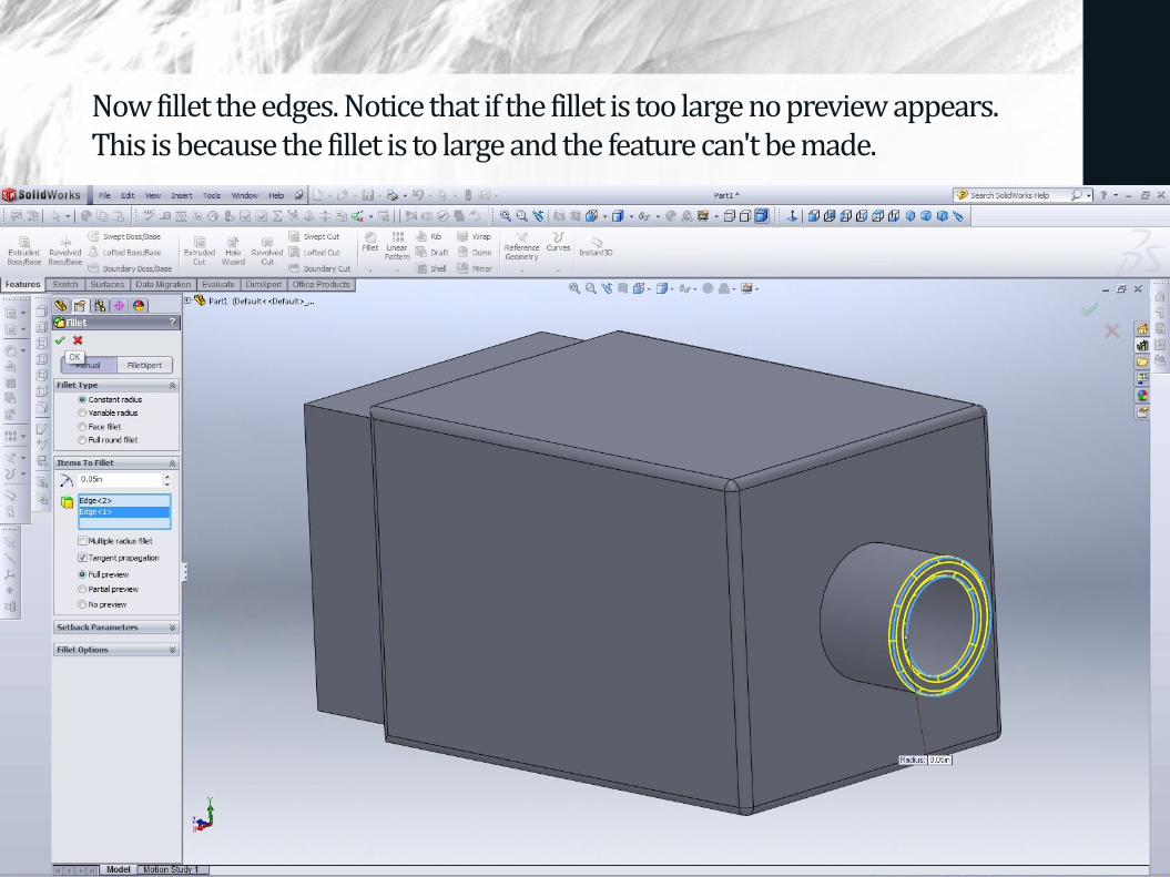
Now fillet the edges. Notice that if the fillet is too large no preview appears. This is because the fillet is to large and the feature can't be made.
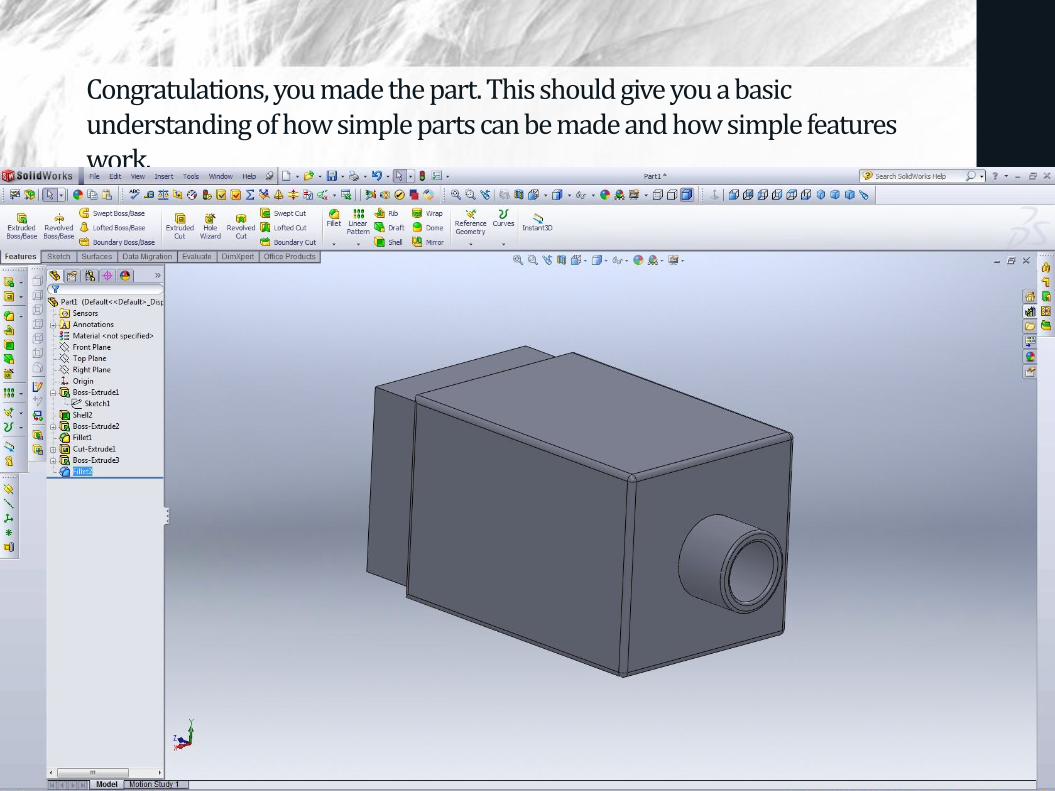
Congratulations, you made the part. This should give you a basic understanding of how simple parts can be made and how simple features work.
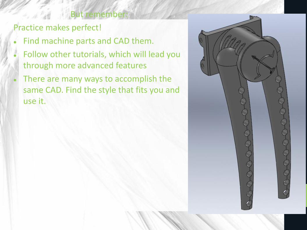
But remember:
Practice makes perfect!
Find machine parts and CAD them.
Follow other tutorials, which will lead you through more advanced features
There are many ways to accomplish the same CAD. Find the style that fits you and use it.

References
To learn more see the Inventor suite, which students can get for free at http://students.autodesk.com/
Or, if you have access to SolidWorks, see the SolidWorks tutotorials.