mechanical behavior, testing, and manufacturing properties of materials group 4: brenton elisberg,...
Post on 22-Dec-2015
221 views
TRANSCRIPT

Mechanical Behavior, Testing, and Manufacturing Properties of Materials
Group 4: Brenton Elisberg, Michael Snider, Michael Anderson, and Jacob Hunner

Overview
• Metals can be processed into various shapes by deforming them plastically under the application of external forces. The effects of these forces on material behavior are described in this chapter, including:
Overview
• Types of tests for determining the mechanical behavior of materials.
• Elastic and plastic features of stress-strain curves and their significance.
• Relationships between stress and strain and their significance, as influenced by temperature and deformation rate.
• Characteristics of hardness, fatigue, creep, impact, and residual stresses, and their role in materials processing.
• Effects of inclusions and defects in the brittle and ductile behavior of metals.
• Why and how materials fail when subjected to external forces.

Section 2.1 – 2.2.6
• Tension Test– Strength – Ductility – Toughness– Elastic Modulus– Strain-hardening
capability• Test Specimen
– Usually solid and round– Original Gauge length lo– Cross-sectional area Ao
Tension
• Stress-strain curves– Linear elastic: elongation in the specimen that
is proportional to the applied load.– Engineering stress: the ratio of the applied
load P, to the original cross-sectional area, Ao, of the specimen.
• Engineering stress equation: σ = P/Ao
• Engineering strain equation: e = (l-lo)/lo

Tension
• Yield Stress: the stress at which permanent (plastic) deformation occurs.
• Permanent (plastic) deformation: stress and strain are no longer proportional.
• Ultimate tensile strength (UTS): the maximum engineering stress.

Tension
• If the specimen is loaded beyond its UTS it begins to “neck.”
• Fracture stress: the engineering stress at fracture.

Tension
• Modulus of elasticity: ration of stress to strain in the elastic region.– Modulus of elasticity equation: E = σ/e
• This linear relationship is known as Hooke’s Law.
• Poisons Ratio: the ratio of the lateral strain to the longitudinal strain.

Ductility
• Ductility: extent of plastic deformation that the material undergoes before fracture.
• Two measures of ductility:– Total elongation: (lf-lo)/lo x 100%
– Reduction of Area: (Ao-Af)/Ao x 100%
True-Stress and True-Strain
• True-stress: ratio of the load, P, to the instantaneous cross-sectional area, A, of the specimen.
• True-strain: the sum of all the instantaneous engineering strains.– True-stress equation: σ = P/A
– True-strain equation: e = ln(l/lo)

Construction of Stress-Strain Curves
• The stress-strain curve can be represented by the equation: σ = Ken
– K = strength coefficient – n = strain hardening exponent
• Specific energy: energy-per-unit volume of the material deformed.

Construction of Stress-Strain Curves

Strain at Necking in a Tension Test
• True-strain at necking is equal numerically to the strain-hardening exponent, n, of the material.

Temperature Effects
• As temperature increases:– Ductility and toughness
increase.– Yield stress and the
modulus of elasticity decrease.
• Temperature also affects the strain-hardening exponent of most metals, in that n decreases as temperature increases.

Section 2.2.7 – 2.7
• Rate of Deformation
• Superplasticity
• Effects of Compression, Torsion, and Bending
• Hardness, Toughness, and Strength

Rate of Deformation Effects
• Some machines form materials at low speeds.– Hydraulic Presses
• Some Machines form materials at high speeds.– Mechanical Presses

Rate of Deformation Effects
• Deformation rate: the speed at which a tension test is being carried out, in units of m/s or ft/min.
• Strain rate: a function of the specimen length.
• Short specimens stretch more during the same time period than a long specimen would.

Effects of Temp and Strain
Typical effects that temperature and strain rate have together on the strength of metals:– Sensitivity of strength-to-strain rate increases with
temperature. – Increasing the strain rate increases the strength of
the material (strain-rate hardening). – The slope of these curves is called the strain-rate
sensitivity exponent. – The relationship between strength and strain is
represented by: = Cem
– C is the strength coefficient and e is the true strain rate. m is the slope of the graph.
Rate of Deformation Effects
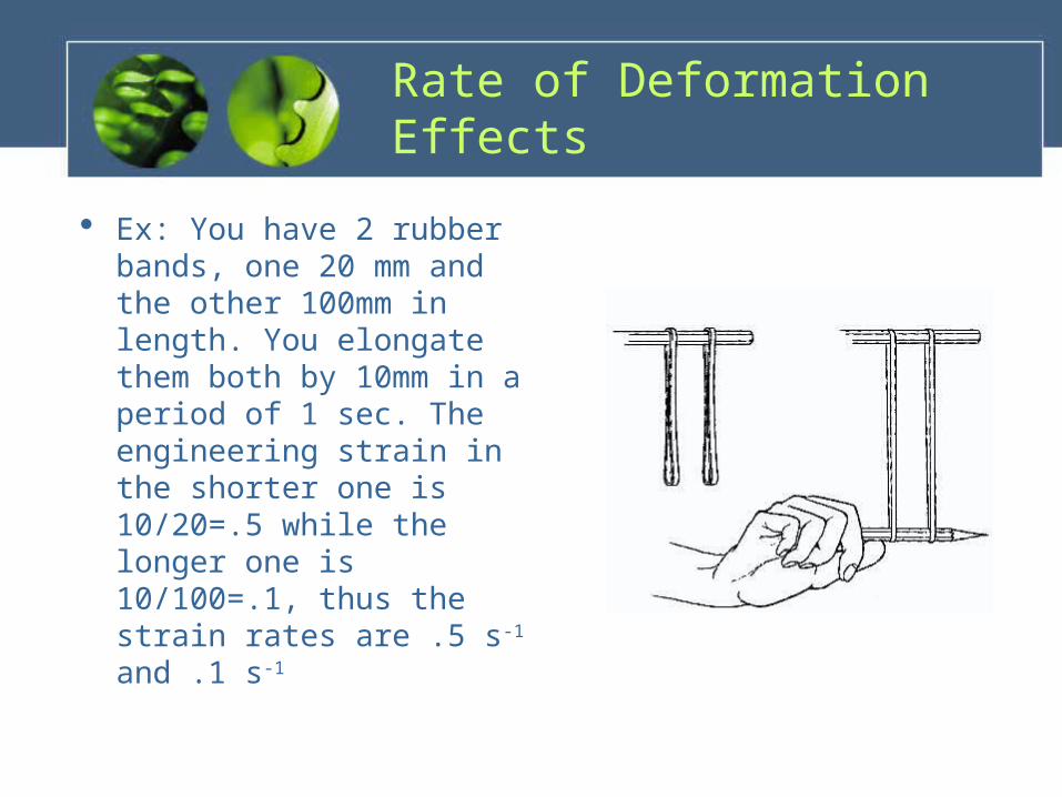
Ex: You have 2 rubber bands, one 20 mm and the other 100mm in length. You elongate them both by 10mm in a period of 1 sec. The engineering strain in the shorter one is 10/20=.5 while the longer one is 10/100=.1, thus the strain rates are .5 s-1 and .1 s-1

Superplasticity
• Refers to the capability of some materials to undergo large, uniform elongation prior to necking and fracture.
• This elongation can be as long as 200% to 2000% of the original length.
• Common items that demonstrate this: bubble gum, glass (at high temp) and thermo plastics. – Because of this capability, some materials can be
formed into complex shapes such as beverage bottles and even neon advertisement signs.

Other Deformation Effects
• Hydrostatic Pressure: pressure due to weight of a fluid.
• Exposing some types of metals to high radiation is known to increase yield stress, tensile strength, and hardness. However it decreases ductility and toughness.
• Increasing hydrostatic pressure can increase the strain at fracture of materials. – Billet: A semi-finished form of steel that is used for long
products such as bars and channels.– Creating hydrostatic pressure on a billet can turn 1 m of
billet into 14 km of wire.

hydraulic press.htm

Compression
• Many operations in manufacturing, especially with forging, rolling, and extrusion, are performed with the material being subjected to compressive forces.

Compression Test
A specimen is subjected to a compressive load.
Carried out by compressing a solid cylindrical specimen between two well-lubricated flat dies.
The cylindrical specimen’s surface begins to bulge, known as barreling.

Disk Test
• Compression test developed for brittle materials such as ceramics and glass.
• A disk shaped specimen is loaded between to solid platens. Tensile stresses build up perpendicular to the centerline along the disk, fracture begins, and the disk will split vertically.
• Tensile stress from this test can be calculated with the following equation: = 2P/dt P is load at fracture, d is diameter of disk, t is thickness.

Torsion Test
• In addition to tension and compression, a work-piece may be subjected to shear strains. – Punching holes in sheet metal. – Metal cutting.
• Torsion test used for determination of properties in “shear.” Usually performed on a thin tubular specimen.
• Shear stress can be calculated with formula: T/2r2t – T is torque, r is average radius of tube, t is thickness of tube.
• Shear strain is calculated with formula: rФ/l– r is radius of tube, Ф is angle of twist in radians, and l is length of
tube.
Torsion Test
• The ratio of the shear stress to the shear strain in the elastic range is known as the shear modulus or modulus of rigidity.
• The angle of twist, Ф, to fracture in the torsion of solid round bars and elevated temp can help estimate forge-ability of metals.

Bending
• Preparing specimens from brittle materials, such as ceramics and carbides, is difficult because of problems in shaping and machining them to certain dimensions.
• The most common test for brittle materials is the bend or flexure test.

Bend / Flexure Test
• Rectangular specimen supported at its ends.
• Load is applied vertically at 1 or 2 pts.
• The stress at fracture in bending is known as the modulus of rupture, flexural strength, or transverse rupture strength.

Hardness
• Commonly used property which gives indication of the strength and resistance to scratch and wear of a material/specimen. – Resistance to permanent indentation.– Hardness is not a fundamental property
because indentation depends on shape of indenter and load applied.

Brinell Test
• J. A. Brinell 1900• Involves pressing a steel
or carbide ball of 10mm against a surface with various loads. – 500, 1500, or 3000 kg
• Measures diameter of indentation.
• Harder surfaces have small indentation while softer surfaces have larger indentation.

Rockwell Test
• S. P. Rockwell 1922• Test measures depth
rather than diameter of indentation.
• Diamond indenter presses against surface with minor load and then major load. – The difference in depths of
penetration is a measure of the hardness of material.
Vickers Test
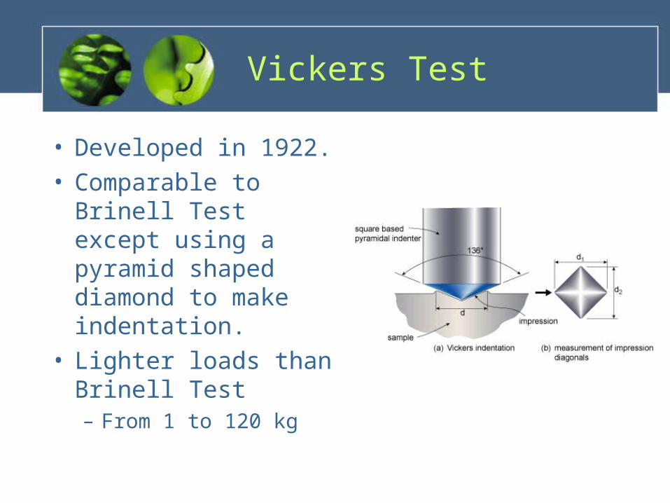
• Developed in 1922.• Comparable to Brinell
Test except using a pyramid shaped diamond to make indentation.
• Lighter loads than Brinell Test– From 1 to 120 kg

Knoop Test
• Developed in 1939. • Comparable to Brinell and Vickers test.• Uses an elongated pyramid shaped diamond to make
indentations. • Uses very light loads.
– From 25 g to 5 kg.
• Known as a micro-hardness test because of the lights loads.– Suitable for very small or very thin specimens.
• Test also used for measuring the hardness of individual grains and components in a metal alloy.
Mohs Hardness Test
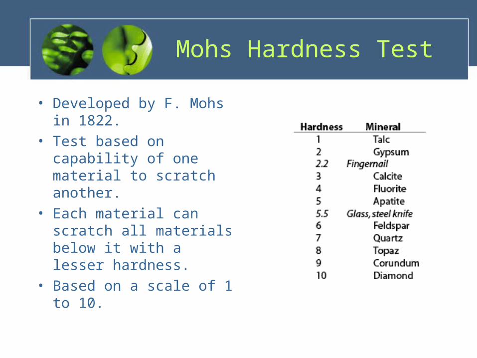
• Developed by F. Mohs in 1822.
• Test based on capability of one material to scratch another.
• Each material can scratch all materials below it with a lesser hardness.
• Based on a scale of 1 to 10.

Scleroscope
• Instrument with diamond-tipped hammer.
• Hammer is dropped from a certain height.
• Hardness is related to the rebound of the indenter.
• Small and portable.

Durometer
• Used to test hardness of plastics, rubbers, and other soft materials.
• An indenter is pressed against the surface and then a constant load is applied rapidly.
• Hardness is measured based on depth of indent after 1 second.

Section 2.7 – 2.12
Fatigue
• Fatigue – Components in manufacturing equipment are subjected to fluctuating cyclic (periodic) loads and static loads.
• Cyclic Stress – on gear teeth
• Thermal Stress -- cool die in repeated contact with hot work pieces– Both stresses may cause part failure at stress
levels below normal static stress loading

Fatigue
• Fatigue Failure -- Failure associated with every stress cycle, propagated through the material until critical crack is reached and material fractures.
• Fatigue Testing -- Various stresses, tension then bending to a maximum load limit (total failure.)

Fatigue
• S-N Curves– Stress Amplitude (S) --
Maximum stress specimen is subjected
– Number of Cycles (N)• Level of stress a
material tolerates decreases with an increase in cycles.

Fatigue
• Endurance (Fatigue Limit) -- Maximum stress material may be subjected without fatigue failure.– Aluminum Alloys and similar materials exhibit
an indefinite endurance limit.– Fatigue strength is specified at a certain
number of cycles (10^7.)– Carbon Steels have a proportional endurance
limit and tensile strength, usually 0.4 to 0.5.

Creep
• Permanent elongation of a component under a static load maintained for a period of time.
• Grain-Boundary Sliding -- Mechanism of creep at an elevated temperature in metals.– In high-temperature applications, gas-turbine blades,
jet engines, and rocket motors.– May occur in tools and dies subjected to constant
elevated temperatures (forging and extrusion.)

Creep
• Creep Testing -- Subjecting a specimen to a constant tensile load (engineering stress) at a certain temperature, measuring the length changes at various time increments.– Primary, secondary, and
tertiary stages

Creep
• Rupture (Creep Rupture) -- Failure by necking and fractures– Creep rate increases with specimen
temperature and the applied load.– Secondary Linear ranges and slopes aid to
determine reliable design.– A higher melting point generally is related to
an increase in creep resistance.• Stainless Steels, Super-alloys and Refractory
metals and alloys

Creep
• Stress Relaxation -- The stresses resulting from loading of a structural component decrease in magnitude over a period of time, while the dimensions of the component remain constant.– Thermoplastics

Impact
• Testing consists of placing a notched specimen in an impact tester and breaking it with a swinging pendulum.– Impact or Dynamic
Loading
• CharpyTest -- Specimen supported at both ends.
• Izod Test -- Specimen supported at one end.

Impact
• Impact Toughness -- The energy dissipated in breaking the specimen may be obtained from the amount of swing in the pendulum.– Useful in determining the ductile-brittle
transition temperature of materials.• High Impact Resistance – High Strength – High
Ductility – High Toughness

Impact
• Notch Sensitivity -- Sensitivities to surface defects, lowers impact toughness.– Heat-treated metals,
Ceramics, and Glasses

Failure and Fracture of Material
• Failure -- One of the most important aspects of material behavior. It directly influences the selection of a material for a particular application, the methods of manufacturing, and the service life of the component.

Failure and Fracture of Material
• In selecting and processing materials – Fracture -- Either internal or external. Sub-classified
into Ductile or Brittle.– Buckling -- Longitudinal deformation under
compression, similar to barreling.• Some products are designed with failure essential for their
function:– Food and Beverage containers with tear tabs– Shear pins on shafts to prevent damage if overloaded– Perforated paper or metal (packaging)– Metal or plastic screw caps for bottles

Failure and Fracture of Materials
• Ductile Fracture -- Plastic deformation proceeds failure.– Highly ductile materials neck down to a point
before failing.– Most metals and alloys will neck down to a
finite area and then fail.– Generally ductile fractures take place along
planes which shear stress is a maximum.
Failure and Fracture in Materials
• Ductile Fracture -- Plastic deformation proceeds failure.– Close examination of ductile fracture surface
shows a fibrous pattern with dimples.• Failure is initiated with formation of tiny voids which
grow and coalesce, developing micro-cracks leading to fracture.
– In tension-test, fracture begins at the center of the necked region as a result of the growth and coalescences of cavities.

Failure and Fracture in Material
• Cup-and-Cone Fracture -- Due to appearance, the fracture surface of a tension-test specimen.

Failure and Fracture in Materials
• Effects of Inclusions -- May consist of impurities of various kinds and of second-phase particles, such as oxides, carbides, and sulfides.– Extent of influence depends on their shape,
hardness, distribution, and fraction of total volume.
• Higher Volume fraction of inclusions, the lower the ductility of the material.
Failure and Fracture in Materials
• Effects of Inclusion cont’d– Two factors affect void formation
• The strength of the bond at the interface between an inclusion and the matrix.
• The hardness of the inclusion: a soft inclusion will conform to the overall shape change of the work-piece.
– Mechanical Fibering from the alignment of inclusions during plastic deformation.
– Subsequent processing of material must involve considerations of the proper direction of working for maximum ductility and strength.
Failure and Fracture in Material
• Transition Temperature -- Across a narrow temperature range many metals undergo a sharp change in ductility and toughness.– The phenomenon occurs mostly in body-centered
cubic and in some hexagonal close-packed metals, rarely exhibited by face-centered metals.
– Transition Temperature depends on composition, microstructure, grain size, surface finish and shape of the specimen, and deformation rate.
– Transition Temperature raises with high rates of deformation, abrupt changes in work-piece shape, and the presence of surface notches.
Failure and Fracture in Material
• Strain Aging -- Phenomenon in which carbon atoms in steels segregate to dislocations thereby pinning them and increasing the resistance to dislocation movement. Resulting in increased strength and reduces ductility.
• Accelerated Strain Aging – Phenomenon occurs in a few hours at a temperature higher than room temperature.

Failure and Fracture in Material
• Blue Brittleness -- Occurs in the blue-heat range where steel develops a bluish oxide film.
• Blue Fracture -- Occurs with little or no gross plastic deformation.
• In tension, fracture takes place along the cleavage plane (crystallographic plane), where the normal tensile stress is a maximum.
– Low temperature and a high rate of deformation promote brittle fracture.
– The fracture surface of polycrystalline metal under tension has a bright granular appearance.

Failure and Fracture in Material
– Tensile stresses normal to the cleavage plane, initiate and control the propagation of fracture.
• Chalk, Gray Cast Iron, and Concrete

Failure and Fracture in Material
• Defects -- Scratches, flaws, and pre-existing external or internal cracks.– The high tensile stresses subject the tip of the crack to
propagate the crack rapidly due to the materials inability to dissipate energy.
– Catastrophic failure occurs under tensile stresses when compared to their strength in compression.
• Trans-granular -- Crack propagates through the material.

Failure and Fatigue in Material
• Inter-granular -- Crack propagates along the grain boundaries, generally when the grain boundaries are soft, contain a brittle phase, or have been weakened by liquid- or solid-metal embrittlement.

Failure and Fracture in Material
• Fatigue Failure -- Minute external or internal cracks develop at pre-existing flaws or defects in the material. The cracks propagate over a period of time and leads to total and sudden failure of the part.

Failure and Fatigue in Material
• Beach Marks -- Term given the fracture surface in fatigue.
• Striations -- On the fracture surface, several appearing on each beach mark.

Failure and Fatigue in Material
• Improving Fatigue Strength -- Fatigue life is influenced greatly by the method of preparation to the surfaces of the part or specimen.– Fatigue Strength of manufactured products may be
improved overall by• Inducing compressive residual stresses on surfaces
– Shot Peening or Roller Burnishing
• Case hardening (surface hardening) by various means

Failure and Fatigue in Material
– Fatigue Strength of manufactured products may be improved overall by
• Providing a fine surface finish and thereby reducing the effects of notches and other surface imperfections.
• Selecting appropriate materials and ensuring that they are free from significant amounts of inclusions, voids, and impurities.

Failure and Fatigue in Material
• Factors and processes that may reduce fatigue strength: decarburization, surface pits (corrosive) acting as stress raisers, hydrogen embrittlement, galvanizing, and electroplating.
• Stress-Corrosion Cracking -- Either over a period of time or soon after being manufactured, parts free from defects may develop cracks.

Failure and Fracture in Material
• Stress-Corrosion Cracking -- cont’d– Crack propagation may be inter- or trans-granular.– Susceptibility of metals to stress-corrosion cracking
depends mainly on the material, on the presence and magnitude of tensile residual stresses and on the environment (Salt water and other chemicals.)
– To avoid Stress-Corrosion cracking stress relieve the part after it is formed. Full annealing may be done, but reduces the strength of cold worked parts.

Failure and Fatigue in Material
• Hydrogen Embrittlement -- The presence of hydrogen may reduce ductility and may cause severe embrittlement and premature failure in many metals, alloys, and nonmetallic materials.– Especially severe in high-strength steels.
• Melting of Metal, Pickling (removal of surface oxides by chemical or electrochemical reaction,) Electrolysis in Electroplating, Water Vapor in the Atmosphere, Moist Electrodes, and fluxes in Welding
– In copper alloys, Oxygen may also cause embrittlement.

Residual Stresses
• Work-pieces are subjected to plastic deformation that is not uniform throughout the part. Stresses remain within a part after it has been formed and all the external forces are removed.– The bending of a metal bar. The elastic and plastic
deformation resulting in a permanent bending.• The linear load reaches the yield stress, changing non-
uniformly. The release of the external force is opposite the curvilinear load (elastic.) The difference in the two loads gives the residual stress pattern within the bar. Compressive residual stresses in ad and oe, tensile residual stresses in od and ef.

Residual Stresses
• Warping -- Disturbances of residual stresses acquire a new radius of curvature to balance the internal forces.
• Temperature Gradients within a body may also cause residual stresses (cooling or forging.)– Contractions and Expansions within a material
produce non-uniform deformation (beam or lumber.)• Tensile residual stresses on a surface are
undesirable due to the reduction in strength when an external force is applied to the part (brittle, less ductile.)

Failure and Fatigue in Material
• Compressive residual stresses on a surface are desirable. – Shot Peening and Surface Rolling
• Reduction and Elimination of Residual Stresses -- Either by stress relief annealing or by further deformation of the work-piece.– Stress Relaxation may occur over time, and may
increase greatly by raising the temperature of the work-piece.

Work, Heat, and Temperature
• Almost all of the mechanical work of deformation in plastic working is converted into heat.
• Stored Energy -- A portion of work stored within the deformed material as elastic energy. – 5 to 10% of total energy input, in some alloys
may be as high as 30%

Work, Heat, and Temperature
• Change of Temperature is the ratio of specific energy to the density and specific heat of material.– Higher Temperatures are associated with large areas
under the stress-strain curve and with smaller values of specific heat.
– Physical properties as specific heat and thermal conductivity depend on temperature and must be taken in account during calculations.
– If deformation process is performed rapidly, the heat losses will be relatively small over that brief period.
– If the process is carried out slowly, the actual temperature rise will be only a fraction of the calculated value.

Work, Heat, and Temperature
– Specific Energy (u) -- Work of deformation per unit volume
– Density (d)– Specific Heat of
Material (c)

Chapter 3

Physical Properties of Materials
• Engineers must make conscious function and performance decisions based on the physical properties of materials

• Overview– Density– Melting point– Specific heat– Thermal conductivity– Thermal expansion– Electrical, magnetic and optical properties– Corrosion resistance
Physical Properties of Materials – Ch. 3

Density
• Mass per Unit Volume
– Typical units include• kg/m^3• lb/ft^3
• Specific Gravity– Density with respect to
water– No units

Density
• Strength-to-Weight ratio– Specific Strength– Tensile strength /
density
• Stiffness-to-Weight ratio– Specific Stiffness– Elastic modulus /
density
• Units of length

Melting Point
• The energy required to separate the atoms of a material– Units of temperature
• Important consideration when the material will be subject to an operating temperature or a thermal cycle during manufacturing process– Annealing– Heat treating– Hot working

Specific Heat
• The energy required to raise the temperature of a unit mass by one degree
• Units of J/kg ˚K• Important consideration in the forming or
machining operations

Thermal Conductivity
• The rate at which heat flows within and through a material
• Units of W/m ˚K• Very low thermal
conductivity of Titanium– Can result in excessive
tool wear during machine operations

Thermal Expansion
• The expansion or contraction of a material when exposed to a thermal cycle
• Units of µM/m ˚C
• Hot rivets are installed through holes in steel plate• When the rivets cool they contract causing an extremely tight
compressive stress on the joint
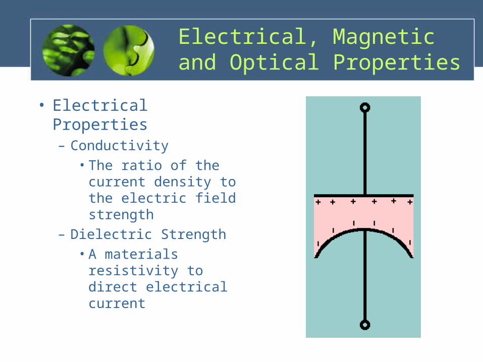
Electrical, Magnetic and Optical Properties
• Electrical Properties– Conductivity
• The ratio of the current density to the electric field strength
– Dielectric Strength• A materials
resistivity to direct electrical current

Electrical, Magnetic and Optical Properties
• Electrical Properties– Conductors– Superconductors– Semiconductors– Piezoelectric effect
• A reversible interaction between an elastic strain and an electric field
• Typical applications include pressure transducers, sensors, and strain gauges

Electrical, Magnetic and Optical Properties
• Magnetic Properties– Ferromagnetism– Ferrimagnetism– Magnetostriction
• The expansion or contraction of a material when subjected to a magnetic field
• The principle behind ultrasonic machining equipment

Electrical, Magnetic and Optical Properties
• Optical Properties– Color– Opacity

Corrosion Resistance
• Corrosion– Typically used to
describe metal or ceramic deterioration
– Similar phenomena occur in plastics
– Often referred to as degradation
Corrosion Resistance
• Types of corrosion– Pitting– Intergranular– Crevice– Galvanic cell– Stress-corrosion cracking– Selective Leaching– Oxidation– Passivation

Corrosion Resistance
• Pitting– Can occur over the
entire surface or be localized
• Intergranular– Occurs along grain
boundaries

Corrosion Resistance
• Crevice– Occurs at the interface of
bolted or riveted joints
• Galvanic cell– Occurs between dissimilar
metals when an electrolyte is present
– Not as common in pure metals or single-phase alloys

Corrosion Resistance
• Stress-corrosion cracking– Cold worked metals
are most susceptible
• Selective leaching– Occurs when
metalworking fluid attacks specific elements in tool and die materials

Corrosion Resistance
• Oxidation– A chemical reaction which leaves a small layer
of oxidized material on the surface– Resists further corrosion
• Aluminum & Titanium
• Passivation– The development of a protective film by
chemical reaction• Stainless Steel

• Review– Density– Melting point– Specific heat– Thermal conductivity– Thermal expansion– Electrical, magnetic and optical properties– Corrosion resistance
Physical Properties of Materials

• http://www.hardwaresquare.com/category/hardware/nails/• http://www.boeing.com/companyoffices/gallery/images/space/delta_i
v/d4_1st_heavy_24.html• http://en.wikipedia.org/wiki/Density• http://www.nyu.edu/pages/mathmol/textbook/density.html• TEXTBOOK• http://www.american-carbide.com/EndMills/DHEM.aspx• http://www.roymech.co.uk/Useful_Tables/Rivets.html• http://hyperphysics.phy-astr.gsu.edu/hbase/electric/conins.html• http://en.wikipedia.org/wiki/Oxidation

http://www.materialsengineer.com/G-Pitting-Corrosion.htm• http://www.corrosion-doctors.org/Forms/intergranular.htm• http://www.textronfasteningsystems.com/appsol/galv_corr.html