mechanical and el auto saxophone muhammad …
TRANSCRIPT

PERPUSTAKAAN UMP
100 1111111111 DD lU 0000080232
MECHANICAL AND EL AUTO SAXOPHONE
MUHAMMAD SHUKRAN BIN ZAINI
Thesis submitted in fulfillment of the requirements for the award of the degree of
Bachelor of Mechatronic Engineering
Faculty of Manufacturing Engineering UNIVERSITI MALAYSIA PAHANG
V
OCTOBER 2013

V
ABSTRACT
Saxophone is most commonly associated with jazz and classical music. As the sound waves are produced by an oscillating reed, the saxophone is categorized as woodwind instruments. Different pitches from the saxophone are produced by opening and, closing keys. In order for a person to play the saxophone seamlessly, he or she need to have good respiratory control and fingering skills. Although fingering skills is much easier to be acquired compared to the respiratory control, but it still need a plenty of training and practices. As for the respiratory control, a saxophonist will have to control the volume and speed of the exhale air in order to produce a desired tone. In order to achieve that, the person should have good breath control and large lungs capacity. As conclusion from above, it is hard to develop a good saxophonist among us. The MIDI Auto Saxophone is a platform intended to be the replacement for the saxophonist for instance when a saxophonist is needed immediately. MIDI Auto Saxophone is one of the project that build autonomous device that .play musical instrument by means of conversion of the MIDI message file into digital signal and then being sent to air pressure control system and fingering system. This project is then intended to develop the mechanical and electrical support for the MIDI Auto Saxophone.

VI
ABSTRAK
Saksofon adalah alat muzik yang sering dikaitkan dengan jazz dan muzik kiasik. Oleh kerana bunyi yang terhasil dihasilkan oleh getaran buluh, saksofon dikategorikan sebagai instrumen woodwind. Pcrbezaan nada daripada saksofon dihasilkan membuka dan menutup kekunci. Perkara yang paling penting bagi seseorang untuk bermain saksofon dengan lancer, dia perlu mempunyai kawalan pernafasan yang baik dan kcmahiran pengawalan jar. Walaupun kemahiran pengawalan jar adalah lebih mudah untuk diperolehi berbanding dengan kawalan pernafasan, tetapi ia masih memerlukan banyak latihan. Bagi kawalan pernafasan, pemain saksofon perlu mengawal kuantiti dan kelajuan udara yang dihembus demi untuk menghasilkan nada yang dikehendaki. Untuk itu, seseorang itu haruslah mempunyai kawalan pernafasan yang baik dan saiz paru-paru yang besar. Kesimpulannya, adalah sukar untuk melatih seorang dari kalangan kita untuk menjadi pemain saksofon yang baik. MIDI Auto Saxophone adalah salah satu platform yang dibina dengan tujuan untuk menjadi pengganti kcpada pemain saksofon sekiranya pemain saksofon diperlukan secara mendadak. MIDI Auto Saxophone adalah salah satu projek yang membina alat autonomi yang bermain alat muzik dengan cara menukar fail mesej MIDI kepada isyarat digital dan kemudian dihantar ke sistem kawalan tekanan udara dan sistem penjarian. Projek mi pula bertujuan untuk membangunkan sokongan mekanikal dan elektrikal untuk MIDI Auto Saxophone.

TABLE OF CONTENT
Page
SUPERVISOR'S DECLARATION
STUDENT'S DECLARATION
ACKNOWLEDGEMENTS iv
ABSTRACT V
ABSTRAK
TABLE OF CONTENTS
LIST OF TABLES ix
LIST OF FIGURES
LIST OF SYMBOLS xi
LIST OF ABBREVIATIONS xii
CHAPTER 1 INTRODUCTION
1.1 Introduction 1
1.2 Project Background 2
1.3 Problem Statement 3
1.4 Objectives 3
1.5 Scope of Project 3
1.6 Significant of Project 3
CHAPTER 2 LITERATURE REVIEW
2.1 Introduction 5
2.2 Alto Saxophone 5
2.3 Fingering Chart of Alto Saxophone 8
2.4 Supporting Structure 9
2.5 Fingering Mechanism 10
Vii

viii
CHAPTER 3 METHODOLOGY
3.1 Actuator Type 11
3.2 RC Servo Motor . 12
3.3 Electrical Block Diagram 13
3.4 Controlling Circuit 14
3.5 Power. Source 14
3.6 Mechanical Structure 15
CHAPTER 4 RESULT AND DISCUSSION
4.1 Servo Motor 17
4.2 Controlling Circuit 18
4.3 Power Source 21
4.4 Finger Mechanism 22
CHAPTER 5 CONCLUSION AND RECOMMENDATION
5.1 Conclusion 25
5.2 Recommendation 26
REFERENCES . 27
APPENDICES
A Diagram of Pressed Key Travel Distance 28
B Fix-Position Servo Coding 29
C Sweep-Movement Servo Coding 30

LIST OF TABLES
Table No. Title Page
4.1 Current consumption for a servo motor 18 4.2 AND gate truth table 19
lx

LIST OF FIGURES
Figure No. Title Page
2.1 Clarinet 6 2.2 Oboe 6 2.3 Basic saxophone structure 7 2.4 Example of saxophone fingering chart 8 2.5 WAS-2 robot 9 2.6 Finger mechanism composed of a RC servo motor and a direct link
connected to the motor axis 10 3.1 RC servo motor 12 3.2 Electrical block diagram for the finger mechanism 13 3.3 Proposed frame for the mounting structure 15 4.1 Controlling circuit 19 4.2 Graph of switching signal 20 4.3 Etched board with soldered components 21 4.4 Human finger mechanism 22 4.5 Internal of the finger mechanism 23 4.6 Complete finger mechanism 24
X

LIST OF SYMBOL
Hz Hertz V Voltage
Degree Kg.cm Kilogram-centimeter % Percentage A Ampere
xi
LIST OF ABBREVIATIONS
MIDI Musical Instrument Digital Interface
I/O Input/Output
RC Radio Control
PWM Pulse Width Modulation
USB Universal Serial Bus
DC Direct Current
CMOS Complementary Metal Oxide Semiconductor
xli

CHAPTER 1
INTRODUCTION
1.1 INTRODUCTION
Music is an art form whose medium is sound and silence. Its common elements
are pitch, rhythm, dynamics, and the sonic qualities of timbre and texture. To many people
in many cultures, music is an important part of their way of life. A musical instrument is
a device created or adapted for the purpose of making musical sounds. One of the
instruments is the saxophone.
Saxophone is a musical instrument that belongs to woodwind instrument family.
They are made of brass and played with a single reed mouth piece similar to playing
clarinet. Although it is made from brass, they are not categorized as brass instruments but
instead as the woodwind instruments as the sound waves are produced by oscillating reed.
Originally it is popular in military bands; saxophone soon beame a part of' pular Plo music
and jazz.
There are many types of saxophone that exist. Some of the well-known saxophone
is Soprano Saxophone, Alto Saxophone, Tenor Saxophone, and Baritone Saxophone.
Soprano Saxophone is the type of saxophone that is more difficult to learn and not
advisable for beginning players. The reason is that correct embouchure is critical to play
this type of saxophone successfully and newbies may find it difficult to precisely form
the needed embouchure. This is in the key of B flat and may either be curved or straight.

2
Alto Saxophone is medium sized and the most commonly played type of
saxophone. The alto saxophone would be perfect for a beginner to start with. It is curved
with a smaller mouthpiece and is in the key of E flat.
Tenor Saxophone is larger than the alto saxophone and is in the key of B flat. The
mouthpiece is also larger, the rods and tone holes are longer. This is the type of saxophone
commonly used in jazz music. The neck of the tenor saxophone is prone to damage due
to its length.
Baritone Saxophone is the largest among the common types of saxophones. The
baritone saxophone may or may not have an extension attached to the end of the horn. If
it has an extension it is called a low A baritone. Due to its size and shape, the baritone is
quite prone to damage.
1.2 PROJECT BACKGROUND
The invention of the MIDI Auto Saxophone is actually an initiative to build up an
autonomous device that play saxophone instrument based on input signal in the form of
MIDI. This device is combination of a few elements including MIDI decoder program,
Digital I/O, reed control and electromechanical actuator. Mounting mechanism should be
taken into consideration in order to house the rest of the elements and also to support
function of device properly such as the actuator mechanism, without propeimountin g, it
cannot actuate on the right key as it was designed to.
Taking WASEDA Saxophonist Robot as an example, it is a well-known robot that
is capable of playing saxophone instrument on a par with an intermediate saxophone
player. These are the humanoid robots that are inspired, invented and programmed based
on human's body part mechanism.

3
1.3 PROBLEM STATEMENT
As the device will play the saxophone without the aid from human, it will be
needed to mount the saxophone onto the device. How can the saxophone be mounted so
that it can be played automatically by the device? As there are total number 23 keys on
the Alto Saxophone, correct actuation of key is needed in order to play the saxophone
correctly. How to construct the electrical circuit so that the signal will be sent to the right
actuator? How to build actuator mechanism so that it can behave like human finger? Thus,
this project is intended to answer the above problem.
1.4 OBJECTIVE
> To build a support structure to firmly hold the saxophone.
> To build finger-like mechanism to mechanically press the saxophone keys.
> To construct the electrical circuit to support the finger-like mechanism.
1.5 SCOPE OF PROJECT
The scope for this project is to construct a mounting frame in order to hold and
carry the weight of the saxophone. The frame should only fit alto saxophone only. Next
part is to assemble 18 fingers mechanism that have the same response time. \The last scope
is to construct electrical circuit to initiate the correct finger mechanism based on the input
signal which is the switching signal.
1.6 SIGNIFICANT OF PROJECT
' The development of MIDI Auto Saxophone project may have benefits in various
sector. Apart from gaining understanding on the saxophone instrument, this project can
grant the researchers and the developers with valuable knowledge. Taking the frame
itself, knowledge on structural and architectural could be gained.

ri
The issue on how to mechanically press the saxophone keys will lead on to the
study of the anatomy of the human body part, mainly finger. This study may give benefit
in the medicine sector, which may help to develop hand prosthesis. This will later give
help to those who lost their hand.
The construction and development of the electrical circuit would give knowledge
on the digital I/O and logic gate system. The knowledge gained added with in-depth study
may enable a person to develop microcontroller which then dedicated to a specific task
or job. This would give benefit to the market and open up some job vacancies that will
help our own countrymen.

CHAPTER 2
LITERATURE REVIEW
2.1 INTRODUCTION
This chapter reviews about previous study that has been done in order to develop
the saxophonist robot. Proper and deep understanding on the previous study is required
in order to have a rough idea on how to start any project. In-depth analysis is also needed
as it gives out some suitable component, device and method that can be used in this
project.
2.2 ALTO SAXOPHONE
The alto saxophone is a member of the family of wind instruments that was
invented by Adolphe Sax in 1840. The alto saxophone is made of brass with a tapered
bore. It has single reed which is similar to a clarinet (Figure 2M) and a fingdring system
is based on that of the oboe (Figure 2.2). It is smaller than the tenor saxophone'but larger
than the soprano saxophone.
The alto and tenor saxophone are the most common types of saxophone. The alto
saxophone is commonly present in saxophone ensembles, concert and symphonic bands,
and big bands. The alto saxophone is often used as solo instrument in rock, Rock n' Roll,
rhythm and blues, and jazz genres. Some saxophones are nickel, silver or gold plated.

Figure 2.1: Clarinet.
Source: http://www.skymusic.com.au/images/Products/5345jpg.
Figure 2.2: Oboe.
Source: http://www.mso.se/uploadlBarn-och-Skolallnstrumentskolaloboe45O.iPg.
The saxophone instrument consists of several prts. By referring to Figure 2.3, the
first is "neck" or also called as the "gooseneck", which is a metal tube that'is attached to
the body of the saxophone. It is removable except for a soprano saxophone. Next part is
"octave vent and keys" which can be divided into two parts. The "octave vent" is a single
hole and key located on the neck of the saxophone. Next to that is a flat metal key called
the "octave key". The next part is the "mouthpiece" which is found on the neck of the.
saxophone. A cork is needed so that the mouthpiece can slide in. This is where the
musician places his lips and blows air into the instrument to produce sound.

7
The next part is the "body" which is a conically shaped brass tube that has plates
attached to it and holds the rods, keys and other parts of the saxophone. The straight part
of the body is called the tube. The u-shaped bottom of the sax is called the bow. The flared
part of the sax is called the bell. "Thumb rest" is a hook-shaped piece of plastic or metal
where you place your right thumb to support the sax.
"Keys" may either be made of brass or nickel and often some or all of the keys
are covered with mother-of-pearls. The keys on the middle and lower part of the bow are
called spatula keys. The keys on the bottom right side are called side keys. "Rods" is one
of the most important parts of the saxophone in terms of its performance that should be
strong and well maintained. "Pads" covers the holes of the saxophone enabling it to
produce different sounds. The pads must completely cover the tone holes. They also have
a resonator to help in sound projection.
Figure 2.3: Basic saxophone structure.
Source: http://www.saxophone.com/images/saxmap.gif.

8
2.3 FINGERING CHART OF ALTO SAXOPHONE
In music, fingering is the choice of which fingers and hand position to use when
playing certain musical instruments. Depending on the instrument, not all the fingers may
be used. For example, saxophonists do not use the right thumb and string instruments
usually use the fingers. A substitute fingering is an alternative to the indicated fingering,
which, when applied, will produce the same desired tone.
Fingering of woodwind instruments such as saxophone is not always simple or
intuitive, depending on how the acoustic impedance of the bore is affected by the
distribution and size of apertures along its length, leading to the formation of standing
waves at the desired pitch. Several alternate fingerings may exist for any given pitch
In order for saxophone to produce desired tone, a combination of pressed keys is
needed while the air flows through the saxophone body. The combination of the keys is
called the Fingering Chart (Figure 2.4).
Figure 2.4: Example of saxophone fingering chart.
Source: http://www.saxophone-players.com/image-files/fcl.jpg.

2.4 SUPPORTING STRUCTURE
Supporting structure of the MIDI Auto Saxophone is important as this is where
the saxophone is being put on and is where all the mechanism and accessory parts are
being mounted. The support should able to withstand all weight of loads and inertia forces
that subjected by the saxophone and all the fingering mechanism respectively. Referring
to the WAS-2 robot (Figure 2.5), it has strong and firm structure, as the robot was able to
hold the saxophone firmly.
Figure 2.5: WAS-2 robot.
Source:
S-2.jpg.
10
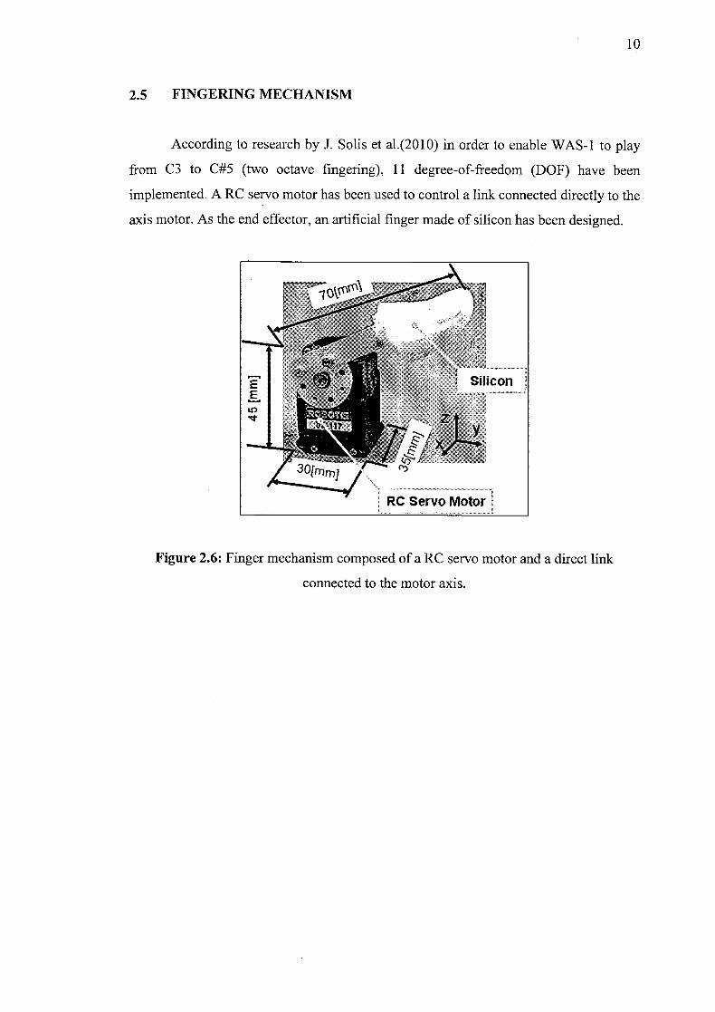
2.5 FINGERING MECHANISM
According to research by J. Solis et al.(2010) in order to enable WAS-1 to play
from C3 to C#5 (two octave fingering), ii degree-of-freedom (DOF) have been
implemented. A RC servo motor has been used to control a link connected directly to the
axis motor. As the end effector, an artificial finger made of silicon has been designed.
rTIii: i Silicon
Nt
3Oimrnj
RC Servo Motor
Figure 2.6: Finger mechanism composed of a RC servo motor and a direct link
connected to the motor axis.

CHAPTER 3
METHODOLOGY
3.1 ACTUATOR TYPE
A servo motor is a closed-loop servomechanism that uses position feedback to
control its motion and final position. The input to its control is some signal, either
analogue or digital, representing the position commanded for the output shaft. The motor
is paired with some type of encoder to provide position and speed feedback. In the
simplest case, only the position is measured.
The measured position of the output is compared to the command position, the
external input to the controller. If the output position differs from that required, an error
signal is generated which then causes the motor to rotate in either direction, as needed to
bring the output shaft to the appropriate position. As the positions approach, the error
signal reduces to zero and the motor stops. The very simplest servomotors use position-
only sensing via a potentiometer and bang-bang control of their motor. They form the
basis of the simple and cheap servo motor.
Servo motors are generally used as a high performance alternative to the stepper
motor. Stepper motors have some inherent ability to control position, as they have inbuilt
output steps. This often allows them to be used as an open-loop position control, without
any feedback encoder, as their drive signal specifies the number of steps of movement to
rotate.

12
This lack of feedback though limits their performance, as the stepper motor can
only drive a load that is well within its capacity, otherwise missed steps under load may
lead to positioning errors. The encoder and controller of a servo motor are an additional
cost, but they optimize the performance of the overall system relative to the capacity of
the basic motor.
3.2 RC SERVO MOTOR
RC servo motor are hobbyist remote control device servos typically employed in
radio-controlled models, where they are used to provide actuation for various mechanical
systems such as the steering of a car, the control surfaces on a plane, or the rudder of a
boat. Due to their affordability, reliability, and simplicity of control by microprocessors,
RC servo motor are often used in small-scale robotics applications. RC servo motors are
composed of an electric motor mechanically linked to a potentiometer.
Figure 3.1: RC servo motor.
Source: http://www.servocity.comlassets/images/HS-625MG.JPg.
RC servos are composed of an electric motor mechanically linked to a
potentiometer. A standard RC servo receive P'WM signals with a 50Hz frame rate. The
electronics inside the servo translate the width of the pulse into a position. When the servo
is commanded to rotate, the motor is powered until the potentiometer reaches the value
Corresponding to the commanded position.

13
In order to measure the response time for the actuator, Agilent Modular Instrument
can be used. While the servo motor is functioning, the current consumption can be
measure by using Agilent USB Modular Digital Multimeter. As this experiment is
developed in order to see the response time, Agilent USB Modular Oscilloscope is used
to measure the actuatiofltime of the servo motor.
3.3 ELECTRICAL BLOCK DIAGRAM
Pe wave from I MIDI codeder unit L
DC power
Switching signal Controlling circuit ' I ftom MIDI decoder
Figure 3.2: Electrical block diagram for the finger mechanism.
Since the RC servos require PWM signal for the positioning input, PWM wave
are required to be supply to the servos. The MIDI decoder unit uses Arduino platform as
the central processing unit, it has simplify the need for the PWM wave as the Arduino
itself can generate its own PWM wave signal.
In the attempt to provide PWM wave signal, called as ON PWM signal for the
total number of 18 servos, a different approach is needed. In order to reduce the demand
for the PWM wave, a PWM wave signal with specific duty cycle need to be provide to
several servos. This approach will then reduce the pin required for the PWM wave, as the
pin for PWM output is quite limited on the Arduino platform.
Since the RC servo uses a train of reduction gears, it would need a quite high force
in order to push back the servo to its previous initial position. The keys of the saxophone
does not have that much of capability. Thus, an additional PWM wave, called as OFF
PWM signal will be provided to every servo that is not triggered by the ON PWM signal

14
wave. As the result, the shaft of the servo can move back to its pre-determined initial
position without the need of external forces.
3.4 CONTROLLING CIRCUIT
Since every servo is provided with two PWM wave signal which is the ON PWM
signal and OFF PWM signal, a controlling circuit is needed in order to determine which
PWM wave will be transmit to the servo. The selection of the wave will be based on the
switching signal that is generated from the MIDI message signal by the decoder unit. The
switching signal is a simple digital signal.
3.5 POWER SOURCE
The RC servo are connected through a standard three-wire connector, in which
one of them is use for transmitting PWM signal and the other two is for the DC power
supply. Although the Arduino platform has the pin to supply 5V to other equipment, but
it will not be enough to power up all the 18 servos. Thus, an external and dedicated power
supply with the correct rating is needed in order to supply the servos with sufficient
power.
In order to determine the power requirement of the RC servo, a simple experiment
can be conducted. An Arduino platform loaded with the correct coding (ARVEN DIX B)
which is use to move the servo to a position and some jumper wire is required in'order to
carry out this experiment. While the RC servo motor is holding to its position that loaded
in the Arduino code, measure the current that flow through the servo while at the same
time apply some external force onto the servo's output shaft.
Another experiment can be conducted in order to determine the current while the
servo is moving. Load the Arduino platform with a code that vary the PWM duty cycle
over time (APPENDIX C), that will make the RC servo sweep back and forth between 00
to 180 0 . While the servo motor is sweeping back and forth, some force is apply to counter
its movement and at the same time the current flow is measured.

15
3.6 MECHANICAL STRUCTURE
In order for the mounting structure to be strong enough to support the saxophone
and the supporting unit, which is MIDI decoder unit and reed controller unit, a sturdy and
stable frame is needed. The proposed frame for this project is made from L-shape metal
structure as shown in Figure 3.3. This structure can provide better support than a flat panel
metal with the same thickness. This will allow less material being used for the frame and
save some valuable weight.
Figure 3.3: Proposed frame for the mounting structure.
In order to increase the sturdiness of the frame, four aluminium bat \with thickness
of 3mm in added in slanting position at some crucial point. This will help to shift the
weight from the middle of the frame to the bottom corner end of the frame. This bar will
also help to prevent the middle vertical frame from being pushed downward by the weight
on the frame that will create a sagging effect on the bottom horizontal frame.