mechanical air & vapor installation & parts eliminatorsmechanical...a gas fire in the event...
TRANSCRIPT

Mechanical Air & VaporEliminators
Installation & Parts
Liquid ControLs Group An IDEX Fluid & Metering Business Installation: M300-10

2
Table of ConTenTs
The most current English versions of all Liquid Controls publications are available on our web site, www.lcmeter.com. It is the responsibility of the local distributor to provide the most current version of LC manuals, instructions, and specification sheets in the required language of the country, or the language of the end user to which the products are shipping . If there are questions about the language of any LC manuals, instructions, or specification sheets, please contact your local distributor.
Publication Updates and Translations
InTrodUCTIon
Safety Procedures .................................................... 3Principles of Design ................................................. 5Specifications and Dimensions ................................ 8Aluminum High Mount .................................................8Aluminum High Pressure .............................................9Cast Iron High Mount .................................................10Stainless Steel High Mount ........................................11Steel ...........................................................................12Bulk Plant ...................................................................13Low Mount ..................................................................14
InsTallaTIon
Field Piping ............................................................. 16
MaInTenanCe
Valve Plates & Cover Gaskets ................................ 19Reed Strips & Float Assemblies .............................. 20
bIlls of MaTerIals
Aluminum High Mount ............................................. 21Aluminum High Pressure ........................................ 22Cast Iron High Mount .............................................. 23Stainless Steel High Mount ..................................... 24Steel ........................................................................ 25Bulk Plant ................................................................ 26Low Mount ............................................................... 27
CUsToMer servICe
Contacting the Factory ............................................ 28Return Material Authorization Requests .................. 29
3
safeTy ProCedUres
! WarnInG
• Before using this product, read and understand the instructions.• All work must be performed by qualified personnel trained in the proper application, installation, and
maintenance of equipment and/or systems in accordance with all applicable codes and ordinances.• When handling electronic components and boards, always use proper Electrostatic Discharge (ESD)
equipment and follow the proper procedures• Make sure that all necessary safety precautions have been taken. • Provide for proper ventilation, temperature control, fire prevention, evacuation, and fire management.• Provide easy access to the appropriate fire extinguishers for your product. • Consult with your local fire department, state, and local codes to ensure adequate preparation.• Read this manual as well as all the literature provided in your owner’s packet.• Save these instructions for future reference.• Failure to follow the instructions set forth in this publication could result in property damage, personal injury, or
death from fire and/or explosion, or other hazards that may be associated with this type of equipment.
be Prepared
This manual provides warnings and procedures that are intended to inform the owner and/or operator of the hazards present when using the Liquid Controls Meter on LP-Gas and other products. The reading of these warnings and the avoidance of such hazards is strictly in the hands of the owner-operators of the equipment. Neglect of that responsibility is not within the control of the manufacturer of the meter.
noTICe

4
safeTy ProCedUres
Before disassembly of any meter or accessory component:
ALLINTERNALPRESSURESMUSTBERELIEVEDANDALLLIQUIDDRAINEDFROM THESYSTEMINACCORDANCEWITHALLAPPLICABLEPROCEDURES.
-Pressure must be 0 (zero) psi. -Close all liquid and vapor lines between the meter and liquid source.
For SafetyRulesRegardingLPG, refer to NFPAPamphlet58 and local authorities.
Failuretofollowthiswarningcouldresultinpropertydamage,personalinjury,ordeathfromfireand/orexplosion,orotherhazardsthatmaybeassociatedwiththistypeofequipment.
! WarnInGbe Preparedsafely evacuate Piping system
In The evenT of larGe fIres or fIres ThaT are sPreadInG n Evacuate the building and notify your local fire department. n Stop the leakage only if you can safely reach the equipment.
In The evenT of sMall, ConTaIned fIres ThaT yoU Can safely ConTrol n Stop the leakage if you can safely reach the equipment. n Use the appropriate extinguisher: Class B fire extinguisher, water, fog, etc., depending on the materials. n If in doubt, call your local fire department.
!
!
In the event of a Gas fire
In The evenT of a larGe Gas leak n Evacuate the area and notify the fire department.
In The evenT of a sMall, ConTaIned Gas leak n Stop the leak and prevent accidental ignition. n Prevent the entrance of gas into other portions of the buildings. Some gases, such as LPG, seek lower levels, while other gases seek higher levels. n Evacuate all people from the danger zone. n See that the gas is dispersed before resuming business and operating motors. If in doubt, notify your local fire department.
!
!
In the event of a Gas leak

5
Principles of designLiquid Controls mechanical air and vapor eliminators remove air and vapor from metering systems. Removing the air and vapor from a metering system increases the accuracy of the meter by allowing only liquid to pass through the meter for measurement.
At installation, LC mechanical air and vapor eliminators are piped to a storage tank to provide a pathway and a receptacle where the evacuated air and vapor can be deposited. After the air (or vapor) has left the metering system, mechanical air and vapor eliminators seal off the pathway to prevent liquid from entering the storage tank.
InTrodUCTIon
orIenTaTIon and CoMPonenTsLiquid Controls mechanical air and vapor eliminators are typically bolted, in an upright position, onto the top of a strainer on the inlet side of the meter. Before operation, air and vapor eliminators must be piped to a storage tank and, on most meter systems, to an air check (or differential) valve. Installation and maintenance must be done by a qualified technician. See page 16 for Field Piping installation.
Vent Ports Open
Vent Ports Sealed
aIr and vaPor elIMInaTIonLiquid Controls mechanical air and vapor eliminators eliminate air (or vapor) instantly and continuously as it enters the meter system. Because air and vapor are lighter and less dense than liquid, they are naturally pushed up above the product flow. Air and vapor eliminators are set above the product flow so that air in the system is pushed up into the the cavity inside the air eliminator housing, out the valve plate vent ports, through the piping, and into a storage tank (see middle left figure). As air is evacuated from the system, the liquid level inside the air eliminator cavity is allowed to rise and push the float up. As the float moves up, it presses the reed strips against the valve plate sealing the vent ports and preventing product from passing through the piping and into the strorage tank. If more air enters the system, it will rise to the top of the air eliminator cavity. The air will accumulate there and push the liquid level, and the float, lower. As the float falls, the reed strips pull away from the vent ports, and air can be vented before it enters the system.
In this manual, the term “storagetank,” refers to any type of receptacle meant to hold air or vapor expelled from the meter system by an air eliminator. And because mechanical air and
vapor eliminators remove both air and vapor, depending on the application, the terms “air” and “vapor” are interchangeable
throughout this manual.
“storagetank”

6
InTrodUCTIon
Differential Valve Air Check Valve
Valve OpenValve Closed
lIMITed bleed valve PlaTesAfter the air is eliminated and the reed strips pull away from the vent ports, the air pressure on the back side of the spring is relieved and the valve opens. To avoid the system shock sustained by an abruptly opened valve, the pressure must be released slowly. In order to do this, a ″ bleed hole has been drilled into one of the valve plates so that it sits over a bypass port. The small bleed hole gradually releases the pressure on the valve spring allowing it to open it slowly.
lIMITed bleed Tee asseMblIesSome Liquid Controls mechanical air eliminator models are designed withot bypass ports in their housings (for example, bulk plant air eliminators). For those models to retain the functions of a limited bleed valve plate, a limited bleed tee assembly can be installed in the piping.
Limited Bleed Tee Assembly
Bypass Ports
Vent Ports
Bleed HoleValve Plates
Housing
Principles of design aIr CheCk and dIfferenTIal valvesAir check and differential valves are spring loaded valves on the outlet side of the meter. Most Liquid Controls meter systems with an air eliminator also have an air check or a differential valve. Air eliminators and air check (or differential) valves work in conjunction to stop the flow of product through the meter until the air is eliminated from the system. In order to do this, the air eliminator and the valve are piped together at installation
Air check (or differential) valves are normally closed, but when the pump starts and pushes product into the system, the valve spring will give way to the flow pressure. In order to keep the valve closed when air is being expelled from the air eliminator, the air from the air eliminator is routed through the piping to the back side of the valve spring. The combined force of the expelled air and the strength of the spring keep the valve closed until the air is eliminated.
Bypass ports provide a pathway through the mechanical air eliminator housing to allow air (or vapor) to pass from one side of the air eliminator to the other while the valve plate vent ports
are sealed.
BypassPorts

7
Principles of designdUal head bUlk PlanT aIr elIMInaTorsBy employing two air eliminators, a high mount air eliminator and a low mount air eliminator, dual head bulk plant air eliminators save the metering system from shocks incurred by recurring small slugs of air (or vapor) and prevent large slugs of air from passing by the air eliminator and through the meter system.
Each time a standard air eliminator removes a small slug of air, it closes the downstream differential valve. When the the differential valve closes at a high flowrate, meter systems can incur a significant hydraulic shock. Repeated shocks of this nature can shorten the life of the metering system.
Dual head bulk plant air eliminators have a high mount air eliminator that eliminate small slugs of air without stopping the product flow through the meter system to save the system from shock. Dual head bulk plant air eliminators also have a low mount air eliminator to remove large air slugs.
Occasionally, large slugs of air can overtake a standard air eliminator, and excess air can blow by the air eliminator and pass through the meter causing inaccurate metering. With a dual head bulk plant air eliminator and a differential valve as part of the metering system, the float in the low mount air eliminator drops in the presence of a large slugs of air, the differential valve senses the presence of air as the pressure above and below the diaphragm, and the valve closes until the large slug of air is removed. When the float rises and the valve opens, the high mount air eliminator removes the remaining air in the vessel.
Dual head bulk plant air eliminators require a differential valve and they can only be mounted in fixed installations. They are ideal for applications when product is being metered into storage from a truck or transport with a pump mounted on the truck.
Single Head Bulk Plant Air Eliminator with Optical Sensor
InTrodUCTIon
Dual Head Bulk Plant Air Eliminator
sInGle head bUlk PlanT aIr elIMInaTor WITh oPTICal sensorThe Single Head Bulk Plant Air Eliminator with Optical Sensor performs the same functions as the Dual Head Bulk Plant Air Eliminator. Both air eliminators use a high mount air eliminator to siphon air without stopping the flow. But instead of a low mount mechanical air eliminator, the Single Head Bulk Plant Air Eliminator with Optical Sensor uses an optical sensor to identify large air slugs. When the optical sensor identifies a large air slug, it instantly signals an electronic preset or register (Toptech’s MultiLoad presets or Liquid Controls’ LectroCount registers). The electronic device closes a downstream control valve, stopping the product flow, and the air slug is quickly vented.
The optical sensor provides several advantages over its mechanical counterpart. The optical sensor’s reponse time is much faster than pneumatic-based mechanical air eliminators. The optical sensor has no moving parts or piping requirements, which can simplify installation and maintenance.
8
sPeCIfICaTIons and dIMensIons
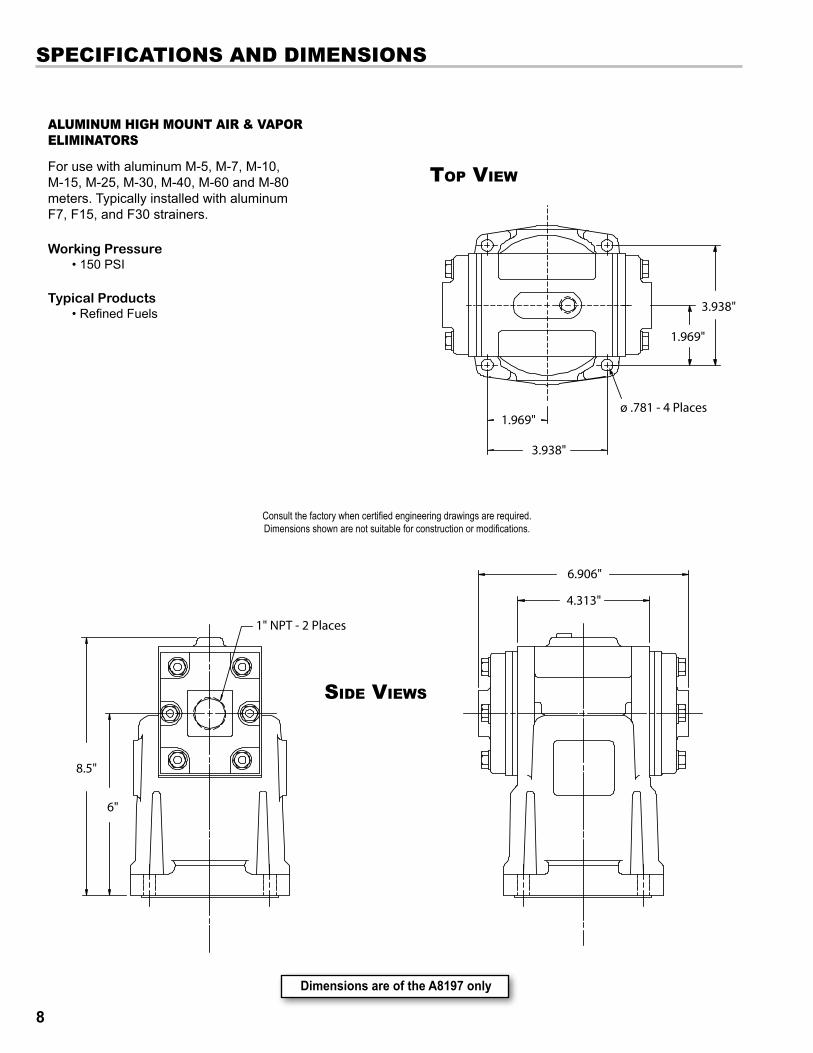
alUMInUM hIGh MoUnT aIr & vaPor elIMInaTors
For use with aluminum M-5, M-7, M-10, M-15, M-25, M-30, M-40, M-60 and M-80 meters. Typically installed with aluminum F7, F15, and F30 strainers.
Working Pressure • 150 PSI
Typical Products • Refined Fuels
6"
8.5"
1" NPT - 2 Places
Top View
Side ViewS
DimensionsareoftheA8197only
Consult the factory when certified engineering drawings are required. Dimensions shown are not suitable for construction or modifications.

9
sPeCIfICaTIons and dIMensIons
Side ViewS
Top View
DimensionsareoftheA8340Aonly
For use with aluminum MA-4, MA-5, and MA-7 and MA-15 meters. Typically installed with the aluminum FA7 strainer.
Working Pressure •350 PSI
Typical Products • LPG • Anhydrous Ammonia
hIGh PressUre alUMInUM aIr & vaPor elIMInaTors
Consult the factory when certified engineering drawings are required. Dimensions shown are not suitable for construction or modifications.

10
CasT Iron hIGh MoUnT aIr & vaPor elIMInaTors
For use with cast iron M-7 meters. Can be installed with cast iron F7 strainers.
Working Pressure • 150 PSI
Typical Products • Chlorinated Solvents
BoTTom View
sPeCIfICaTIons and dIMensIons
Side ViewS
DimensionsareoftheA8977only
Consult the factory when certified engineering drawings are required. Dimensions shown are not suitable for construction or modifications.

11
sTaInless sTeel hIGh MoUnT aIr & vaPor elIMInaTors
For use with stainless steel M-5 class 8 and M-7 class 8 meters. Installed with stainless steel F7 class 8 strainers.
Working Pressure • 150 PSI
Typical Products • Acidic Solutions
sPeCIfICaTIons and dIMensIons
Side ViewS
BoTTom View
DimensionsareoftheA8985only
Consult the factory when certified engineering drawings are required. Dimensions shown are not suitable for construction or modifications.

12
sTeel aIr & vaPor elIMInaTors
For use with MS, MSAA, and MSA series steel case meters. Installed with FS, FSAA, and FSA steel series strainers.
Working Pressure Three models available •150 PSI, 275 PSI and 300 PSI
Typical Products •Refined Fuels • Light Hydrocarbons
sPeCIfICaTIons and dIMensIons
Side View
Top View
DimensionsareoftheA8935only
Consult the factory when certified engineering drawings are required. Dimensions shown are not suitable for construction or modifications.

13
sTeel bUlk PlanT aIr elIMInaTors
For use with aluminum M or MS series meters.
Choices of 3, 4, 6 and 8 inch ANSI flanged connections. Offered in single head, dual head, and single head with optical sensor models to provide high venting capacity for metering into storage systems.
sPeCIfICaTIons and dIMensIons
Side Viewdual head
Top Viewdual head
Dimensionsareofthe4”model
Dimensionsareofthe4”models
Available with ANSI flanges only. Flanges might not match aluminum meters.
Consult the factory when certified engineering drawings are required. Dimensions shown are not suitable for construction or modifications.
single headSide View
Top Viewsingle head
Working Pressure •150 PSI
Typical Products •Refined Fuels
Optical Sensor - Power Input: • +10 to +28VDC • 0.5A maximum

14
sTeel loW MoUnT aIr elIMInaTors
For use with filter/separators.
Working Pressure • 150 PSI
Typical Products • Aviation Fuels
sPeCIfICaTIons and dIMensIons
Top View
Side ViewS
DimensionsareoftheA8175only
Consult the factory when certified engineering drawings are required. Dimensions shown are not suitable for construction or modifications.

15
fIeld PIPInG
field PipingMost Liquid Controls mechanical air and vapor eliminators are shipped from the factory as part of a complete meter system.These air eliminators will arrive bolted to the top of a strainer on the inlet side of the meter.
Before the meter system can be put in operation, the vent ports of the air or vapor eliminator must be piped to a storage tank and/or a valve.
PIPInG To sToraGe TanksBefore operation, air eliminators must be piped to a storage tank. Air eliminators require a receptacle where the eliminated air or vapor can be safely contained. The type of receptacle will vary according to application. Ensure that your receptacle is safe and appropriate for the intended product and its surroundings.
PIPInG To aIr CheCk (or dIfferenTIal) valveIn the case of meter systems for LPG applications, differential valves are often piped to the mechanical vapor eliminator in the Liquid Controls factory before shipment, but for other meter systems, the air eliminator will have to be piped in the field.
Bulk Plant Meter System
Truck Meter System
relieving Internal PressureAll internal pressure must be relieved to zero pressure before disassembly or inspection of the strainer, vapor eliminator, any
valves in the system, the packing gland, and the front or rear covers.
! WarnInG
relieving Internal Pressure Procedure for lPG and nh3 Meters6. Slowly crack the fitting on top of the differential valve to
relieve product pressure in the system. Product will drain from the meter system.
7. As product is bleeding from the differential valve, slowly reopen and close the valve/nozzle on the discharge line. Repeat this step until the product stops draining from the differential valve and discharge line valve/nozzle.
8. Leave the discharge line valve/nozzle open while working on the system.
1. Close the belly valve of the supply tank.
2. Close the valve on the vapor return line.
3. Close the manual valve in the supply line on the inlet side of the meter. If no manual valve exists on the inlet side, consult the truck manufacturer for procedures to depressurize the system.
4. Slowly open the valve/nozzle at the end of the supply line.
5. After product has bled off, close the valve/nozzle at the end of the supply line.
Seriousinjuryordeathfromfireorexplosioncouldresultinperformingmaintenanceonanimproperlydepressurizedandevacuatedsystem.
In this manual, the term “storagetank,” refers to any type of receptacle meant to hold air or vapor expelled
by an air or vapor eliminator such as supply tanks, spewage tanks, catch vessels, spit receptacles, etc.
“storagetank”

16
PIPInG ConfIGUraTIons & ConneCTIons Piping configurations for Liquid Controls mechanical air and vapor eliminators are determined by two factors, the presence or absence of a valve in the meter system and the presence or absence of bypass ports and a limited bleed valve plate in the mechanical air eliminator assembly.
If the meter system has an air check or differential valve, the air or vapor eliminator and the valve must be piped together. If no air check or differential valve exists, you must either plug one of the vent ports (Figure 2) or pipe both vent ports to the storage tank (Figure 3).
Air eliminator models cast without bypass ports cannot be assembled with a limited bleed valve plate at the Liquid Controls factory. To retain the pressure control a limited bleed valve plate provides, a limited bleed tee assembly must be installed in the piping between the air eliminator and the valve (Figure 4).
Under normal circumstances, it is irrelevant which vent port is piped to the valve and which vent port is piped to the storage tank, but there is one exception: air eliminators with an increased venting capacity valve plate. These include part numbers A8201, A8198, A8190, A8188, and A8183. When installing these air eliminators, the increased venting valve plate should be piped to the storage tank, and the limited bleed valve plate should be piped to the valve. The limited bleed valve plate is easily indentified by the notch in the top of the plate (see below).
Limited Bleed Valve Plate
ToAirCheck/DifferentialValve
ToSupply/StorageTank
PIPInG WITh valve
PIPInG WITh no valve
ToSupply/StorageTank
ToAirCheck/DifferentialValve
ToSupply/StorageTank
PIPInG WITh valve
ToSupply/StorageTank
PIPInG WITh no valve
Thepipingconfigurationforeachairandvaporeliminatorseriesisshowninthebillofmaterials.
Figure 1
Figure 2
Figure 3
Figure 4
Standard Valve Plate
When using an electronic valve, product may become trapped between the vapor eliminator and the valve.
fIeld PIPInG
17
fIeld PIPInG
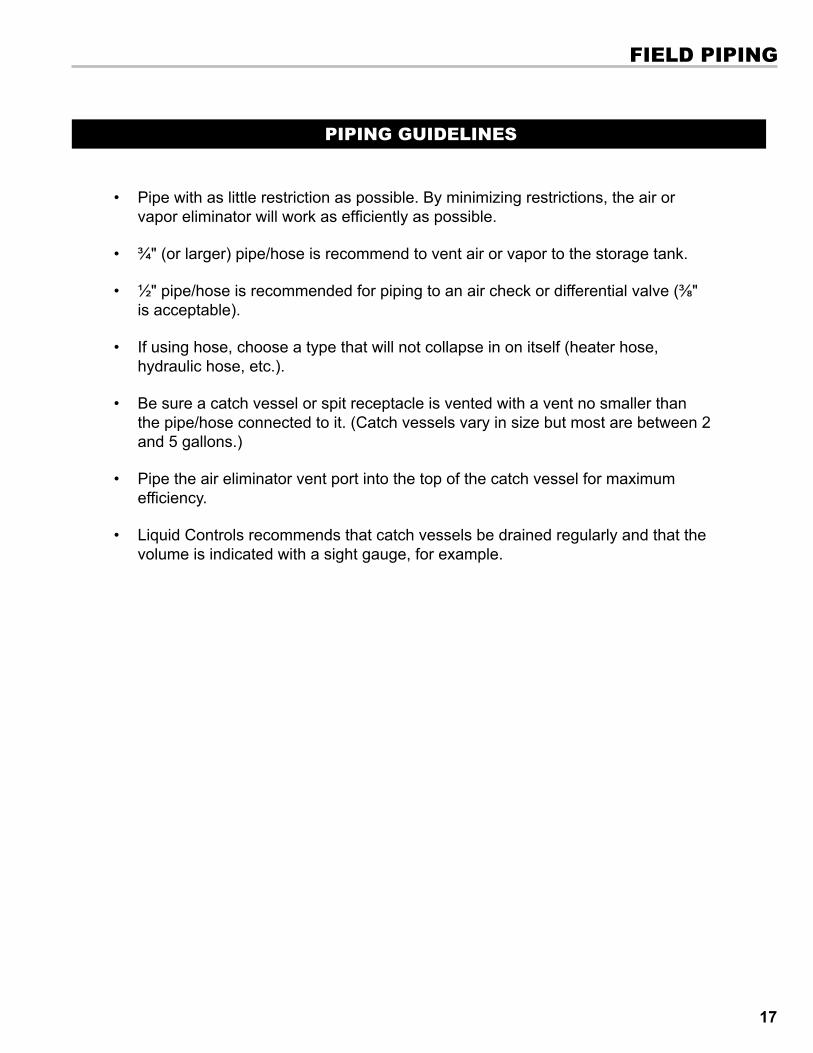
• Pipe with as little restriction as possible. By minimizing restrictions, the air or vapor eliminator will work as efficiently as possible.
• ¾" (or larger) pipe/hose is recommend to vent air or vapor to the storage tank.
• ½" pipe/hose is recommended for piping to an air check or differential valve (⅜" is acceptable).
• If using hose, choose a type that will not collapse in on itself (heater hose, hydraulic hose, etc.).
• Be sure a catch vessel or spit receptacle is vented with a vent no smaller than the pipe/hose connected to it. (Catch vessels vary in size but most are between 2 and 5 gallons.)
• Pipe the air eliminator vent port into the top of the catch vessel for maximum efficiency.
• Liquid Controls recommends that catch vessels be drained regularly and that the volume is indicated with a sight gauge, for example.
PIPInG GUIdelInes

18
To replace the valve Plates & Cover Gaskets
1. Remove the cover screws from the air eliminator cover with a 1/2 inch wrench or socket, and pull the cover, vent plate and seal ring from the housing.
2. Inspect the raised ridge of the vent port opening in the middle of the valve plate for marring or debris. Inspect the seal ring for damage.
3. Replace the seal ring and/or valve plate. Tighten the cover screws to a torque of 17.5 - 20.5 ft-lbs.
MaintenanceThe most common indication of mechanical air and vapor eliminator failure is leakage in and around the cover and valve plate area. Common causes of air eliminator failure are valve plate wear, a broken reed strip, a damaged cover gasket, and a punctured float filled with product.
Besuretorelieveinternalpressureandremoveallproductfromthesystembeforedisassemblingthemechanicalaireliminator.SeeWarningabove.
CoverSealRingValvePlate
VentPort
AirEliminatorPort
MaInTenanCe
relieving Internal PressureAll internal pressure must be relieved to zero pressure before disassembly or inspection of the strainer, vapor eliminator, any
valves in the system, the packing gland, and the front or rear covers.
! WarnInG
relieving Internal Pressure Procedure for lPG and nh3 Meters6. Slowly crack the fitting on top of the differential valve to
relieve product pressure in the system. Product will drain from the meter system.
7. As product is bleeding from the differential valve, slowly reopen and close the valve/nozzle on the discharge line. Repeat this step until the product stops draining from the differential valve and discharge line valve/nozzle.
8. Leave the discharge line valve/nozzle open while working on the system.
1. Close the belly valve of the supply tank.
2. Close the valve on the vapor return line.
3. Close the manual valve in the supply line on the inlet side of the meter. If no manual valve exists on the inlet side, consult the truck manufacturer for procedures to depressurize the system.
4. Slowly open the valve/nozzle at the end of the supply line.
5. After product has bled off, close the valve/nozzle at the end of the supply line.
Seriousinjuryordeathfromfireorexplosioncouldresultinperformingmaintenanceonanimproperlydepressurizedandevacuatedsystem.

19
MaInTenanCe
To replace the reed strips & float assemblies
1. Remove the 4 screws and washers at the base of the air eliminator. Pull the air eliminator off the strainer.
2. Remove the baffle plate and the baffle cup (aluminum air eliminators only) from the housing. If the air eliminator has a lock nut and a bushing on the bottom of the guide post, remove them.
3. Remove the cover screws from the air eliminator cover with a 1/2 inch wrench or socket, and pull the cover, vent plate and seal ring from the housing.
4. To remove a reed strip that is still intact, hold down the reed strip and unscrew the reed screw (shown on the top right). Gently allow the reed strip to straighten. Reed strips violently snap back if they are not held down while removing the reed screw. Failure to hold down the reed strip could result in injury and is the cause of many lost screws.
5. Pull the float, along with the attached reed strips, out from the bottom of the air eliminator (shown on the right). If the float is heavy and full of product, replace it with a new float assembly.
6. If one of the reed strips is broken, remove it and replace with a new reed strip.
7. Begin reassembly. Push the float, along with the attached reed strips, up into the air eliminator cavity. Pull the reed strips out of the side slots (shown on the right). Hold the reed strips down and screw them down with the reed screws. If the air eliminator had a lock nut and a bushing on the bottom of the guide post, replace them.
8. Replace the valve plate, cover gasket, and cover. Tighten the cover screws to a torque of 17.5 - 20.5 ft-lbs.

20
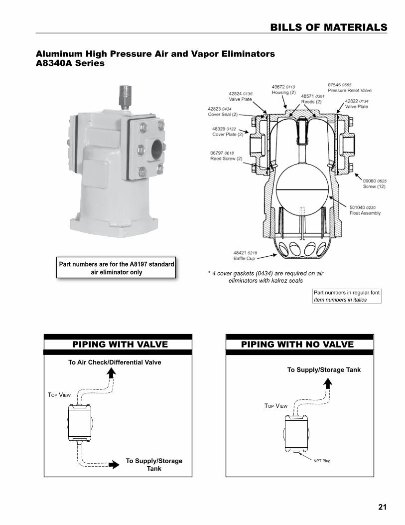
* 4 cover gaskets (0434) are required on air eliminators with kalrez seals
PartnumbersarefortheA8197standardaireliminatoronly
ToAirCheck/DifferentialValve
ToSupply/StorageTank
PIPInG WITh valve
ToSupply/StorageTank
PIPInG WITh no valve
Part numbers in regular font Item numbers in italics
aluminum high Mount air and vapor eliminatorsa8180 series
bIlls of MaTerIals
21
bIlls of MaTerIals
* 4 cover gaskets (0434) are required on air eliminators with kalrez seals
Part numbers in regular font Item numbers in italics
aluminum high Pressure air and vapor eliminators a8340a series
PartnumbersarefortheA8197standardaireliminatoronly
ToAirCheck/DifferentialValve
ToSupply/StorageTank
PIPInG WITh valve
ToSupply/StorageTank
PIPInG WITh no valve

22
Cast Iron high Mount air and vapor eliminatorsa8976 series
PartnumbersarefortheA8977standardaireliminatoronly
ToAirCheck/DifferentialValve
ToSupply/StorageTank
PIPInG WITh valve PIPInG WITh no valve
ToSupply/StorageTank
Part numbers in regular font Item numbers in italics
* 4 cover gaskets (0434) are required on air eliminators with kalrez seals
bIlls of MaTerIals

23
bIlls of MaTerIals
stainless steel high Mount air eliminatorsa8985 series
* 4 cover gaskets (0434) are required on air eliminators with kalrez seals
ToSupply/StorageTank
PIPInG WITh no valve
PartnumbersarefortheA8985standardaireliminatoronly
ToAirCheck/DifferentialValve
ToSupply/StorageTank
PIPInG WITh valve
Part numbers in regular font Item numbers in italics

24
steel air and vapor eliminators with strainer Cover a8930 series
* 4 cover gaskets (0434) are required on air eliminators with kalrez seals
ToAirCheck/DifferentialValve
ToSupply/StorageTank
PIPInG WITh valve PIPInG WITh no valve
ToSupply/StorageTank
PartnumbersarefortheA8935standardaireliminatoronly
Part numbers in regular font Item numbers in italics
bIlls of MaTerIals

25
bulk Plant air eliminatorsa8950 series
ToAirCheck/DifferentialValve
ToSupply/StorageTank
PIPInG WITh valve
PartnumbersarefortheA8170standardaireliminatoronly
Part numbers in regular font Item numbers in italics
a8170
a8950
dUal head PIPInG
bIlls of MaTerIals

26
low Mount air eliminatorsa8175 series
ToAirCheck/DifferentialValve
ToSupply/StorageTank
PIPInG WITh valve PIPInG WITh no valve
ToSupply/StorageTank
PartnumbersarefortheA8175standardaireliminatoronly Part numbers in regular font
Item numbers in italics
bIlls of MaTerIals

27
PIPInG WITh no valve
ToSupply/StorageTank
single head bulk Plant air eliminator with optical sensor
bIlls of MaTerIals
a8170BOM on page 25
Condulet box w/ optical
sensor 81947 optical sensor (sensor only)
WIrInG To leCTroCoUnTlCr-II or lCr 600
Optical Sensor
Out8/Black (54)In5/White (55)
+Vo/Red (56)
84040 or 81920CPU Board
WIrInG To MUlTIload ToPTeCh PreseT
To configure the single head bulk Plant air eliminator with optical sensor to Multiload:
1. Set the number of seconds in Low Flow Time Alarm to the desired time between Optical Sensor detection of air and the valve closing to stop the flow .
2. Configure custom logic: Set Output Port 8 active (Control Valve Enable) when Input Port 9 is active.
A89501-3"A89541-4"A89561-6"

28
Contacting the factory
Before you contact the factory, note the model number and serial number of the component. The serial number directs us to a file containg all information on material specifications and test data applying to your specific component. When ordering parts, the Liquid Controls Group technical manual should be consulted for the proper part numbers. Alwaysincludethemodelnumberandserialnumberwhenorderingparts.
The model and serial numbers are shown on the nameplate of the unit. Record this information for future reference.
Model No.
Serial No.
date PurchaSed
date iNStalled
PurchaSed FroM
iNStalled By
CUsToMer servICe
29
CUsToMer servICe
liquid Controls return Material authorization requests
Return Material Authorization request forms are included in the red literature packet of every Liquid Controls product shipment. They are also available at
www.lcmeter.com under the “Publications” menu selection.
Do not return a Liquid Controls component until all traces of hazardous substances have been removed. For example, substances that have diffused through plastic or remain in crevices.
COSTSINCURREDFORWASTEDISPOSALANDINjURIESDUETOPOORCLEANINGOFRETURNEDLIQUIDCONTROLSCOMPONENTSWILLBECHARGEDTOTHEORIGINATOROFTHERETURN.
! WarnInG
reTUrned MaTerIal aUThorIzaTIon handlInG ProCedUre for hazardoUs MaTerIalsAll returned parts must be cleaned by customers prior to return shipment.The person who actually cleaned the parts is required to complete the Return Material Authorization form. If the component has been contaminated, customers must include an M.S.D.S. sheet with the return shipment. If a part is returned without the proper paperwork, the service department will contact the sender and attempt to procure the correct documents. If the proper paperwork is not received within ten days of receipt, the parts will be sent back to the customer for correction.
Many Liquid Controls employees handle returned components, and they are exposed to substances left behind on the components. It is our intention to make handling these parts as safe as possible. We regret any hardship these stipulations may cause, but because of the many different applications we service, it is a necessary precaution taken to protect our employees.
When returning liquid Controls products for repair, warranty evaluation or calibration, please follow these directions.
1. Remove all residue from the Liquid Controls component(s) to be returned. Make sure the grooves and corners around or inside seals and crevices are cleaned. This is particularly important if the component was in contact with hazardous materials. See Warning and Handling Procedure printed below.
2. Complete the Return Material Authorization request form.
3. If necessary, include special handling instructions, such as MSDS forms or certifications.
4. Attach the completed Return Material Authorization request form, the MSDS form, and the packing slip to the outside of the box.

30

31

105 Albrecht DriveLake Bluff, IL 60044-22421.800.458.5262 • 847.295.1050Fax: 847.295.1057www.lcmeter.com
©2005LiquidControlsPub.No.48406
(3/11)