mece 3321: mechanics of solids chapter 5 · the shaft is made of a992 steel with the allowable...
TRANSCRIPT
10/5/2016
1
MECE 3321:
MECHANICS OF SOLIDS
CHAPTER 5SAMANTHA RAMIREZ
TORSION
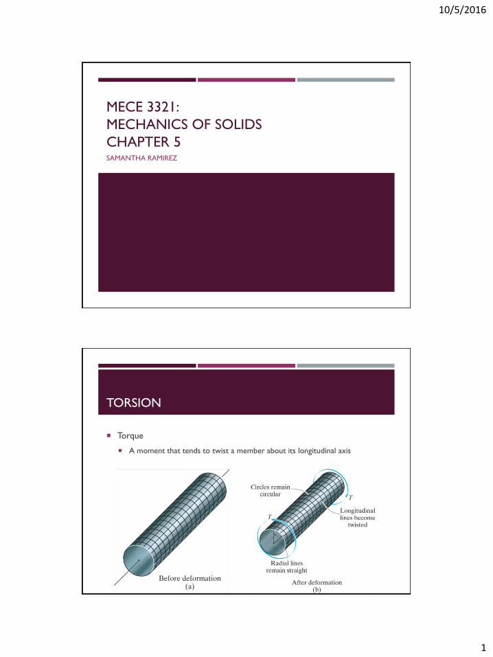
Torque
A moment that tends to twist a member about its longitudinal axis

10/5/2016
2
TORSIONAL DEFORMATION
OF A CIRCULAR SHAFT
Assumption
If the angle of twist is small, the length and radius of the shaft remain the
same
RELATION OF
SHEAR STRAIN TO ANGLE OF TWIST
𝐿𝐵𝐷 = 𝛾Δ𝑥 = Δ𝜙𝜌

10/5/2016
3
TORSIONAL DEFORMATION
OF A CIRCULAR SHAFT
𝛾𝑚𝑎𝑥 = 𝑐𝑑𝜙
𝑑𝑥
𝛾 =𝜌
𝑐𝛾𝑚𝑎𝑥
𝜏 =𝜌
𝑐𝜏𝑚𝑎𝑥
𝜏 = 𝐺𝛾
THE TORSIONAL FORMULA
τmax: maximum shear stress
(occurs at the outer surface)
T: resultant internal torque
J: Polar moment of inertia
c: outer radius of shaft
𝜏𝑚𝑎𝑥 =𝑇𝑐
𝐽
𝜏 =𝑇𝜌
𝐽

10/5/2016
4
POLAR MOMENT OF INERTIA
Solid Circular Shaft
Tubular Shaft
𝐽 =𝜋
2𝑐4
𝐽 =𝜋
2𝑐𝑜4 − 𝑐𝑖
4
HOW TO DETERMINE
INTERNAL RESULTANT TORQUE
If necessary, determine the reactions on the shaft
Section (cut) the shaft perpendicular to its axis at the point where the shear
stress is to be determined
Draw a free-body diagram of the shaft on either side of the cut
Use a static-equilibrium equation and the following sign convention to obtain the
internal torque at the section
Sign Convention
Using the right-hand rule, the torque
and angle of twist will be positive,
provided the thumb is directed
outward from the shaft when the
fingers curl to give the tendency for
rotation.

10/5/2016
5
EXAMPLES
Determine the internal torque at each section.
TORSION DIAGRAM
A torsion diagram is a graphical representation of the internal resultant torque
at any point along a shaft.
Torque
(Nm or lbin)
Distance
(m or in)

10/5/2016
6
EXAMPLES
Draw the torque diagram for each shaft.
PROBLEM 5-3
The solid shaft is fixed to the support at C and subjected to the torsional
loadings shown. Determine the shear stress at points A and B and sketch the
shear stress on the volume elements located at these points.

10/5/2016
7
PROBLEM F5-2
The hollow circular shaft is subjected to an internal torque of T=10 kNm.
Determine the shear stress developed at points A and B. Represent each state of
stress on a volume element.
PROBLEM 5-11
The assembly consists of twosections of galvanized steel pipeconnected together using a reducingcoupling at B. The smaller pipe has anouter diameter of 0.75 in and aninner diameter of 0.68 in, whereasthe larger pipe has an outer diameterof 1 in and an inner diameter of 0.86in. If the pipe is tightly secured intothe wall at C, determine themaximum shear stress developed ineach section of the pipe when thecouple shown is applied to thehandles of the wrench.

10/5/2016
8
PROBLEM 5-44
The rod has a diameter of 0.5 in and weight of 5 lb/ft. Determine the maximum
torsional stress in the rod at a section at A due to the rod’s weight.
POWER TRANSMISSION
Power
The work performed per unit of time
The power transmitted by a shaft subjected to a T and angular
velocity “ω” is:
The size of the shaft can be determined using the allowable shear
stress:
𝑃 = 𝑇𝜔
𝜏𝑎𝑙𝑙𝑜𝑤 =𝑇𝑐
𝐽

10/5/2016
9
PROBLEM F5-8
The gear motor can develop 3 hp when it turns at 150 rev/min. If the allowable
shear stress for the shaft is τallow=12 ksi, determine the smallest diameter of the
shaft to the nearest 1/8 in that can be used.
PROBLEM 5-35
The 25 mm diameter shaft on the motor is made of a material having an
allowable shear stress of τallow=75 MPa. If the motor is operating at its maximum
power of 5 kW, determine the minimum allowable rotation of the shaft.

10/5/2016
10
PROBLEM 5-31
The solid steel shaft AC has a diameter of 25 mm and is supported by smooth
bearings at D and E. It is coupled to a motor at C, which delivers 3 kW of power
to the shaft while it is turning at 50 rev/s. If gears A and B remove 1 kW and 2
kW, respectively, determine the maximum shear stress developed in the shaft
within regions AB and BC. The shaft is free to turn in its support bearing D and
E.
ANGLE OF TWIST
Recall,
Relationship between shear strain and angle of twist 𝑑𝜙
𝑑𝑥=𝛾
𝜌1
Hooke’s Law 𝐺 =𝜏
𝛾2
Torsional Formula 𝜏 =𝑇(𝑥)𝜌
𝐽(𝑥)3
Plugging (2) into (3) and then (1) into the resulting equation you get an equation
for the angle of twist:
𝜙 = 0𝐿 𝑇 𝑥 𝑑𝑥
𝐽 𝑥 𝐺(𝑥)

10/5/2016
11
ANGLE OF TWIST
Assuming a homogeneous material with a
constant cross-sectional area and applied
torque,
φ: the angle of twist of one end of the shaft
with respect to the other end, measured in
radians
T: the internal torque at the arbitrary position
x
J: the shaft’s polar moment of inertia
G: the shear modulus of elasticity or the
modulus of rigidity
𝜙 =𝑇𝐿
𝐽𝐺
SIGN CONVENTION
Using the right-hand rule, the
torque and angle of twist will
be positive, provided the
thumb is directed outward
from the shaft when the
fingers curl to give the
tendency for rotation.

10/5/2016
12
PROBLEM 5-51
The 60 mm diameter shaft is made
of 6061-T6 aluminum having an
allowable shear stress of τallow=80
MPa. Determine the maximum
allowable torque T. Also, find the
corresponding angle of twist of disk
A relative to disk C.
PROBLEM 5-54
The shaft is made of A992 steel
with the allowable shear stress
of τallow=75 Mpa. If gear B
supplies 15 kW of power, while
gears A, C, and D withdraw 6
kW, 4 kW, and 5 kW,
respectively, determine the
required minimum diameter d of
the shaft to the nearest
millimeter. Also find the
corresponding angle of twist of
gear A relative to gear D. The
shaft is rotating at 600 rpm.

10/5/2016
13
PROBLEM 5-59
The shaft is made of A992 steel. It
has a diameter of 1 in, and is
supported by bearings at A and D,
which allow free rotation.
Determine the angle of twist of B
with respect to D.
STATICALLY INDETERMINATE
TORQUE-LOADED MEMBERS
A torsionally loaded shaft may be classified as statically indeterminate if the
moment equation of equilibrium is not adequate to determine the unknown
torques acting on the shaft.

10/5/2016
14
ANALYZING STATICALLY INDETERMINATE
TORQUE-LOADED MEMBERS
1. Free Body Diagram
2. Geometry of Deformation
3. Plug in resultant loads or displacements
𝑀 = 0 = 𝑇 − 𝑇𝐴 − 𝑇𝐵
𝜙𝐴/𝐵 = 0 = 𝜙𝐴/𝐶 + 𝜙𝐶/𝐵
0 =𝑇𝐴𝐶𝐿𝐴𝐶𝐽𝐺+𝑇𝐵𝐶𝐿𝐵𝐶𝐽𝐺
0 =𝑇𝐴𝐿𝐴𝐶𝐽𝐺−𝑇𝐵𝐿𝐵𝐶𝐽𝐺
(1)
(2)
PROBLEM 5-79
The steel shaft is made from two
segments: AC has a diameter of 0.5
in and CB has a diameter of 1 in. If
the shaft is fixed at its ends A and B
and subjected to a torque of 500
lbft, determine the maximum shear
stress in the shaft. Gst=10.8Msi.
10/5/2016
15
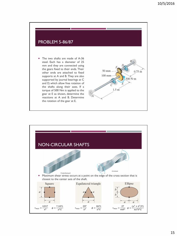
PROBLEM 5-86/87
The two shafts are made of A-36
steel. Each has a diameter of 25
mm and they are connected using
the gears fixed to their ends. Their
other ends are attached to fixed
supports at A and B. They are also
supported by journal bearings at C
and D, which allow free rotation of
the shafts along their axes. If a
torque of 500 Nm is applied to the
gear at E as shown, determine the
reactions at A and B. Determine
the rotation of the gear at E.
NON-CIRCULAR SHAFTS
Maximum shear stress occurs at a point on the edge of the cross section that is
closest to the center axis of the shaft.
𝜏𝑚𝑎𝑥 =4.81𝑇
𝑎3𝜏𝑚𝑎𝑥 =
20𝑇
𝑎3𝜏𝑚𝑎𝑥 =
2𝑇
𝜋𝑎𝑏2𝜙 =7.10𝑇𝐿
𝑎4𝐺𝜙 =46𝑇𝐿
𝑎4𝐺𝜙 =(𝑎2 + 𝑏2)𝑇𝐿
𝜋𝑎3𝑏3𝐺
10/5/2016
16
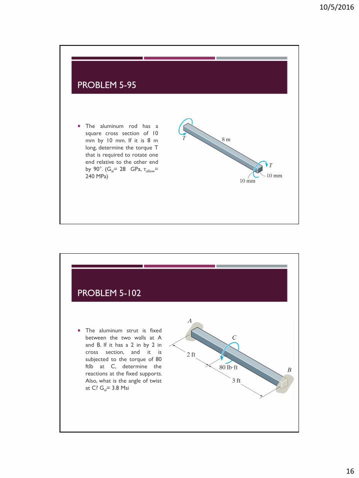
PROBLEM 5-95
The aluminum rod has a
square cross section of 10
mm by 10 mm. If it is 8 m
long, determine the torque T
that is required to rotate one
end relative to the other end
by 90°. (Gal= 28 GPa, τallow=
240 MPa)
PROBLEM 5-102
The aluminum strut is fixed
between the two walls at A
and B. If it has a 2 in by 2 in
cross section, and it is
subjected to the torque of 80
ftlb at C, determine the
reactions at the fixed supports.
Also, what is the angle of twist
at C? Gal= 3.8 Msi

10/5/2016
17
STRESS CONCENTRATION
Under torsion, the shaft will break at the smallest
part of the neck.
𝜏𝑚𝑎𝑥 = 𝐾𝜏𝑚𝑎𝑥,𝑜𝑟𝑖𝑔𝑖𝑛𝑎𝑙 = 𝐾𝑇𝑐
𝐽
TORSIONAL STRESS-CONCENTRATION FACTOR
10/5/2016
18
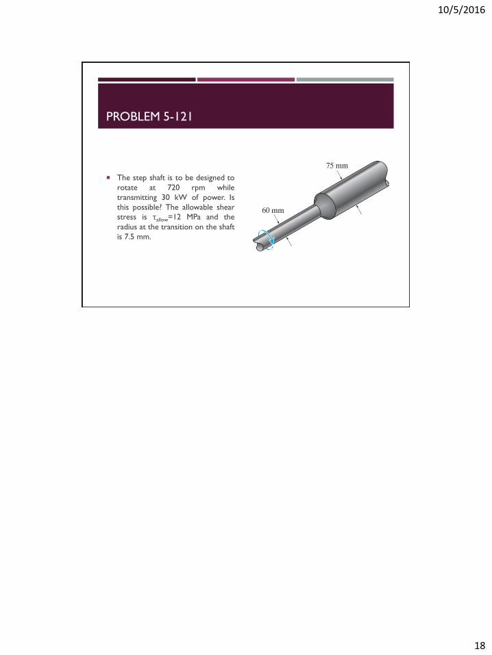
PROBLEM 5-121
The step shaft is to be designed to
rotate at 720 rpm while
transmitting 30 kW of power. Is
this possible? The allowable shear
stress is τallow=12 MPa and the
radius at the transition on the shaft
is 7.5 mm.