measurement of the moments of inertia of the handley...
TRANSCRIPT

C.P. No. 907
MINISTRY OF AVIATION
AERONAUTICAL RESEARCH COUNCIL
CURRENT PAPERS
Measurement of the Moments of Inertia of the Handley Page
HPI 15 Aircraft
by L. I. Fennel/, BSc., A.FR.Ae.5
LONDON. HER MAJESTY’S STATIONERY OFFICE
1967
PRICE 9s bd NET


The attachodvras requested by you:-
b. Please return to this Library by:
If a retentmn copy is requred notify Airfield
Library as soon as possible.
Thank you,
LIB.42


U.D.C. No. 531.231 : 533.6.013.152/154
C.P. No.YW September 1965
KCGWREl:~ OF THE MOMFXS OF IhTWXA OF
THE IiANOLEY PAGE HP115 AIRCRAFT
by
L.- J. Fennell, B.Sc. A2F.R.Ae.S.
Measurement of the moments of inertia in pitch, roll, sxd yaw, and of the
inclination of the prinoxpal inertia axis have been made on the HP115 slenier
wing research aircraft. In pitch and roll a spring constrained osoillatory
technique was used, whde in yaw the airoraft was suspended as a torsional
pendulum. The inclination of the principal inertia axis was found by v&lng
the attitude of the airorxf't on the rolling and yawing rigs. Measurements
were made with fuel tanks full ad empty.
An estimate of the accuraoies of the teohniques used showed that the
.inertias could be measured to within +2$, +$ and il$ for the pitch, roll,
and yaw BXPS respectively. The inclination of the principal axes could be
determind to within tO.1’.
After allowmg for the virtual Inertia of the surrounding air mass, the
experimental values were less than the manufacturers estimates in pitch ad
roll but greater In yaw. The largest discrepancy was approximately $. The
measured inclination of the prlnoxpal axis was considerably less thnn the
estimate, 3.95’ instead of 5.1’.
"Replaces B.A.E. Technical Report No.65203 - A.R.C. 27778

comms
1 I.IVPRO~JCTION
2 TEST METHODS
2.1 Pos3.tion of the centre of gravity 2.2 Moment of inertia in roll
2.3 Moment of inertia in pitch
2.4 Moment of inertia in yaw
2.5 Aerodynami.0 or virtual iwrtia
3 RESULTS
3.1 Centre of gravity
3.2 ibfoment of inertia in roll
3.3 hloment of ulertia m pitch
3.4 Moment of inertia in yaw
4 DISCUSSION OF 33TIXYI'ZD Al4D ?XWXQdENPAL VAIJJES
4.1 Airoratt weight ard 0.g. position
4.2 Moment of inertia of the fuel
4.3 Moment of inertia in roll 4.4 hioment Of inertia in pitch
4.5 EEoment uf inertia in yaw -. 4.6 A, t B-- C;
4.7 Inclination of prinoipal inert& axis
5.. Momms OF INEiiTN FOR FLIGHT 'PEST-mS3LTS
6 CONCLUSIONS Acknowledgements.
Appendix A Deviation of roll equation of motion -
Appendix B Deviation of pitoh equation in motion
Appendix C. Deviation of yaw equation of motion
Appendix D Error analysis
Table 1. summary -of re slilt 3
Table 2 Moaents of inertia in roll
Table 3 >loments of inertia in pitch
Table 4 Moments of inertia in yaw
Table 5 Moments of inertia: for fligl-+t test analysis
Table 6 Typical measurements and possible errors _
Symbols
References
Illustrations Detaohable abstract cards
w
3 4
4
5
7
8
10
II
11
11
13
14
15
15
17
17 i8
18
18
19
j9 20
21
22
23
24
25
26
27 28
28
29
31
33
34 Figures I-15
1 IIVRODUCTIOM
In the determination of aircraft stability derivatives from the an&Y&s
of a programme of flqht manoeuvres, the aoouraoy of the results abtsined till
depend on the values used for the aircraft's moments of inertia and, for the
orientation of its prlnoipal inertia axis.
Cstiwtes of the moment .of znertza are customarily made by the'wnu-faoturer
duri‘ng the design And construction ofthe airoraft. Stioh estimates are liable to
errors because,of the xmpractioability of accounting for every component,
difficdties in the preoise determination of the moments of inertia and oentre of . . gravity positions of intrioate parts, an3 departures from the nominal gauges of
the sheet and. strip from which the airframe is fabricated,
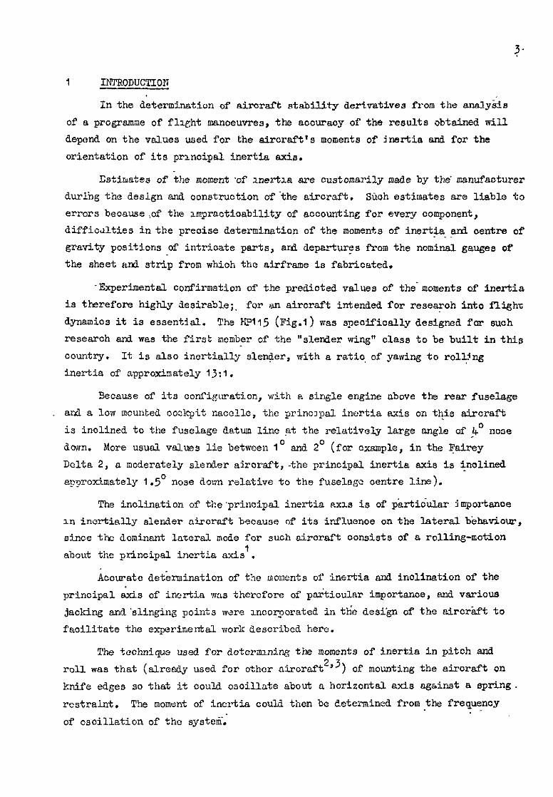
-Experimental oonfirmation of the predioted values of the'moments of inertia
is therefore highly desirable;. for en aircraft intended for researoh into flight
dynamics it is essent9al. The FPl15 (Fig.1) was speoifically designed for such
research and was the first member of the "slender wing" class to be built in this
oountly. It is also inertidly slender, with a ratio, of yawing to roll,!ng
inertia of approximately 13:l.
Secnuse of its oonfi~uration, with R single engine above the rear fuselage
and a loa mcunted oockpit nacelle, the prino3pal inertia axis on this aircraft
is inclined to the fuselage datum line pt the relatively large angle of -4' nose
down. More usual values lie between lo and 2' (for cxsmple, in the Fairey
Delta 2, a moderately slerder ajroraft ,-the principal inertia axis is jjnolined
approximately 1.5' nose do:?n relative to the fuselo$ centre line).
The inolination of tbe~principal inertia ~~1s is of p&ti.dular 3mpcrtanoe
In inertially slerder aircraft because of its irfluenoe on the lateralb&atiour,
since thz dominant lazersl mde for such aircraft consists of 5 rolling-motion
about tie prinoipal inertia axis'.
docurate det'ermination of t5.z moments of inertia and inolination of the
principal &is of inertia was therefore of ps&.ioular importance, And various
jacking and'slinging points ware moonorated in th'c desi'gn of the airoriift to
facilitate the experimental work described here.
The technique used for dcterznniq the moments of inertia in pitoh and
roll was that (alresdy used for other aircraft 2,3) of mounting the airoraft on
knife edges so that it oould oscillate about o horizontal axis against a spring.
restraint, The moment of inertia could tinen be determined from.the frequency
of oscillation of the systelii; -

4
On previous occasions yaw inertia rigs have used torsionless single point
suspension with spring rescraint2, or a bifilar torsional pendulum.
MS.4 have also successfully used an adaptation' of the single point
suspension system for determining the inclination of the principal inertia axis.
Both these techniques have the disadvantage of allowing oscillations in
modes other than yawing, and on this account an attempt in this country2 to
determine the principal atis inclination by the NASA metnod was unsuccessful.
It was therefore decided to adopt a trifilar torsional pendulum system.
This technique effectively prevents osoillation in roll and pitch, although
lateral ani longitudxxal motions are stillpossible; by taking care when
displacing the system from rest such motions can be reduced to nagliable
amounts, and any signlfioant movement readily detected as desoribed in Section 3.4.
Provision was made in both the roll and yaw rigs to vary the pitch
attituie of the aircraft relative to the axis of rotation. By measuring the
moment of inertia over a range of pitch attitude, the principal moments bf
inertia could be determined, as the maximum or minimum values, while the
associated values of pitch attitude gave the inclination of the principal axis
to the fuselage datum.
It was expected that the fuel load mould only make a significant contribution
to the total moment of inertia in the roll case, but that this would also be the
case most susceptible to sloshing of the fuel when the tanks were only partially
filled. Attempts2'3 have previously been made to measure the moment of inertia
in roll of other aircraft with partially filled tanks, but these have not been
entirely successful sznoe, due to sloshing, the moment of snertia apparently
varied with the frequency of oscillation.
It was therefore decided to determine the moments of inertia with tanks
full and tanks empty only, ani to estimate values with part fuel loads when
these oases were needed to evaluate flight test results. The results in Table I
show that the inertia of the fuel-is a small percentage of the total in pitch
ard yaw but is equivalent to 12% of the aircraft empty value in roll.
As an essential preliminary to tic moment of inertia measurements, the
aircraft was weighed and the horizontal and vertical co-ordinates of the centre
of-gravitywere determined. These are also given in Table I.
2 TEST METHODS
2.1 Determination of the position of the centre of gravity
With the aircraft resting on its undercarriage the vertical reactions
at the nose and main wheels will vary as the pitch attitude is changed.

The relation between these reactions and the horizontal distsnoes between the
main whcela, nose wheel, snd aircraft datum is, @%2),
(RR + %4) (2 ccs a + ^e sin a) + s (d2 - d,) - RR d, = 0 (1)
whence bi - d2 RN (RN + I$!)] . se0 a- = 2 + 2 tan a I
(2)
mhere R N and R,! are the reactions at the nose mheel and main wheels, d, is the
horizontal diskance betvreen tne datum point and the main wheels, azxi d2 is that
between the nose and main wheels; a is the pitch attitude, 2 an3 ^z are the
cc-ordinates of the centre of gravity referred to axes parallel and normal to . the fuselage datum (Fig.l), and whose origin is at the datum point., RR and REii
were measured on separate weighbridges whose relative heights cou1d.b.e varied
in +mler to change a. The attitude, a, was measured by a olinometer mounted on
the datum pads inside the fuselage.
The airoraf't datum point used was located on the fuselage undersurface
21 in below the datws line at fuselage station 278. It was 266 in aft of the
fuselage nose or 2Win aft of the wng apex.
2.2 Measurement of the moment of inertia in roll
The rig used is shown in Figs.3 ard I$.. It consist& of a rigid framework
socured to the hangar floor and a variable incidence cradle in ahc.oh the fuselage
rested. The framwork carried Vue blocks at its fore .a&. aft ends to support
oorraspondlng knife edges mounted on the underside of the cradle. A horizon&l,
longitudinal axis wp.3 thus set up below the aircraft centre line, abo& which
the orsdle anl sarcraftcbuld roll. This rotation was restrained by tensc.on
springs attached between the Jacking points under each wing and strong points
m the floor. To remove one so~1poo of constraint t.hs attachment~of the springs
to the wings was made through pairs of crossed knife-edges (Fig.&).
The cradle oonsistsd of two parts hinged together-at the rear and connected
to each other by a screwjack at the front. The lower member carried the knife-
edges and remained horizontal, while the upper member carrird.the aircraft at
attitudes determined by the extension of the sorewjack.
The equation of motion of the system (see Fig.5 and Appendix A) when
displaced through a snail angle y is
-A, y = y [2hy2 - 2Th, (I - h,/&) - Wh2] (3)
6
whence
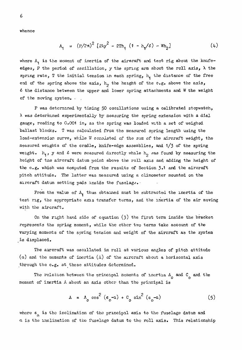
Al = (P/242 [2hy2 - 2Th, (I - hi/!?) - Wh2] (4)
where A., is the moment of' inertia of the airwaft and test rig about the kntie-
edges, P the pericd of oscillation, y the spring arm about the roll axis, h the
spro.ng rate, T the initial tension m each spring, h, the &stance of the free
end of the spring above the axis, h2 the height of the o.g. above the axis,
8 the distance between the upper and lower spring attachments and W the weight
of tk moving system.
P was determined by timing 50 osoxSlat.ions using a calibrated stopwatch,
X was deter&xd experimentally by neasuring the spring extension with a dial
gauge, reading to 0.001 in, as the spring was loaded path a set of' weighed
ballast blocks. T was calculated from the measured spring length using the
load-extension curve, whh41e V consisted of the sum of the aircraft weight, the
measured weights of the cradle, knife-edge assemblies, and l/3 of the spring
weight. h,, y md & were measured dorectly vrhlle h2 iias found by measuring the
height of tne aircraft datum point above the roll axx and adding the height of
the c.g. which was computed from the results of Section 3.1 and the aircraft
pitch attitude. The latter was measured using a clinometer mounted on the
aircraft datum setting pads Inside the fuselag&.-
From the value of A, thus obtained must be subtracted the xkztia of the
test rig, the appropriate axis transfer terms, and the Gsrtia of the air moving
with the aircraft.
On the right hand side of equation (3) the first term inside the bracket
represents the spring moment, while the other two terms take acoount of the
varying moments of the sjpring tension and weight of the aircraft as the system
,is dlsplaced.
The aorcraft was oscillated in roll at various angles of pitch attitude
(a) and the moments of inertia (A) of the alrcraft about a horizontal axis
-through the c.g. . at these attitudes dctcrmined.
The rclatlon between the princxpsl moments of xnertla A, and Co and the
moinent of inertia A about an axis other than the principal is
A = A, ccs2 (~~-a) + Co sin' (do-a) (5)
where E A is the inclination of the proncipal axis to the fuselage datum ard
c. is the inclination of the fuselage datum to the roll axis. This relationship

7
has a minimum value at &o = a and the results for A were platted against the
correspondxng values of a to obtain A, (Fig.10). This curve had a flat minimum,
and to obtain a more preoiae value for E o than could be derived from Fig.10,
equation-(5) was rewritten a8
A= A, + (C - A,) ain' (~~-a) . Cl
Various trial values of E were assumed and, by using the experimental data
for A and a, a series of graphs showing A as a function of sin* (e-a) were
plotted, as In Pigs.11 and 12;
When the aaauxed value of E did not oorrespond to the true Vd’Je, eo,
the experimental data fell onto two distinct ourvea aocording to whether
a-8 5 0. when E = E c, however, all the values were disposed about a single
straight line.
Although the slope of the latter will give the principal moment of inertia
in yaw, Co, it was thought desirable to determine C o directly by an independent
method, aa described in Sections 2.4 and 3.4.
2.3 Mesaurement of the nomcnt of inertia in pitch
The teat rig la shown in Fig.7. To provide an axis parallel to the air-'
craft pitching axis, knife edge blocks were attached to,the underwing jacking
- points and were supported in Vee block8 mounted on heavy Jaoka. A steel channel,
supported on a second pair of heavy duty JaOkS, spanned the front fuselage and
was joined by tension springs to a accord, shorter, steel channel passing beneath
the cockpit. A ataniard jack head on this lower channel engaged with the forward
jacking sooket under the fuselage. In order to reduoe constraints, the crossed
knife-edges of the roll rxg (Fig.4) were again used between the springs ard tne
lower channel mtimber.
The rig was set up 30 that the aircraft datum was horizontal in the
equilibrium poaltion, both longitudinally and laterally, by adjusting the
heights of the appropriate jaoka.
The equation of motion of the system is (see Appendix B and Fig:6),
whence
-B,; = $[hx*- Th, (=-q/d + m21
B1 = (P/2X)2 [xx2 - Th, (i-h+ + Wh2]

8
where B, is the moment of inertia of the aircraft and rig, P the period of
oscrllations, h the spring rate, x the sprrng moment arm about the knife-edges,
h, and h2 the distances of the free end of the suspension and the c.g. of the
combinatxn below the pltchlng axis, & the dlstance between the fixed and free
erfls of the suspension. W tne total moving weaght, T the total initial spring
tension and C$ the displacement angle. P was determined using a calibrated stop
watch to measure the time for 9 oscillations. The sprrng rate was measured as
descrabed in Section 2.2, while T was calculated from the weight of' the aircraft
aid. rig ard the geometry of the system; h, and h2 were derived from measure-
ments taken on the r‘1g, the previously determined position of the axoraft 0.g.
and the computed position of the rig c.g. W comprised the sum of the weights of
the aircraft, the lower crossbeam and knife-edge assemblies of Fig.4 and l/3 of
the weight of the tension springs.
The moment of inertia of the test rig, an axis transfer term, and the
inertia of the air moving with the aircraft must besubtractedfrom the results
for B, to give the structural moment of lnertxa of the aircraft about its centre
of gravity, Bo.
The similarity of equations (8) ati (4) may be noted.
2.4 Moment of inertia in yaw
Ls stated in Section 1, a tnree nire torsional pendulum technique was
adopted. The test rig is shown in Figs.8 and 15 and consisted of a rigid
gantry, bualt from heavy steel sectxons, large enough to span the aircraft.
On the top of the gantry a horizontal 'A' frame was mounted, hinged to the
gantry at the base of the A vrhl1.e the apex could be moved vertically by a
screwjack. Two suspension wires were attached to the base of the 'A' and the
third at a point near the apex. The latter could be moved longxtudinally and
locked in the desired position.
The lower ends of the two rear cables were attached to the ends of the
arms of a Y beam fabricated from heavy steel sections. The third cable was
attached to a point on the upright of the Y which could be moved longitudinally
at-d locked.
Although steel wire cables were originally used for the suspension members
it was suspected that tvrist m the cables could produce unwanted torque. They
were therefore replaced by steel tubes attached to the A frame and Y beam by
aniversal joints which had adequate freedom to rotate about two axes at right
angles to the tubes. The tubes were attached to the uruversal joints through
thrust ball races and were free to rotate through 360' about their axes.

9
At its forward end the Y beam was attached to the axrcraft hy a fork and
bolt to an eyebolt at the auuraft forward slinging pout on the upper fuselage,
just aft of the cookpit. The two rear clvis of the Y be&? were jolned by lu-~ks
to angle brackets bolted to each vru?g upper surface above tl?s undercarriage legs:
These links w&e free to rotate about lateral axes where they were attached to
the Y beam and alrcraf: so as to accommodate longitudinal dimensional differences
between the airoraft snd beam resulting from manufacturing tolerances and distor-
Cmn of arcraft and beam. 'The system was designed so that, in the undistorted
state, the Y beam would be parallel to the fuselage datum Ixne.
By arranging t?e suspension tubes to be of equal length, vertical., and at
equal radii from the e.g. of the alroraft ati Y beam combination, plcchng and
rollrng motions were suppressed. At pitch attitudes other than zero the lower
end of the front suspension tube was not at the same height above the oomblned
cog. as the lower ends of' the two rear tubes. V&en the system was disturbed,
this caused assymetrx loading in the rel,r tubes, snd resulting in small residual
lateral end longitulxrwl forces. However, the maximum values of these were
calculated to be 0.002 lb and 0.1 lb respectively anl. were not consIdered to be
slgnifiaant.
Because tho c.g. of tlx? combination was below the plane contalrung the _
lower ends of,the suspension, changing the aircraft attitude by raising or
lowering the apex of the A frame also changed the radii of the tubes about the
o.g. and it was therefore neoessary to move the forward suspenszon. While it
was possible to compute the required movement for each mcidence, ti5s movement
itself gave rise to a small incidence change. To avoid a prooess of iteration,
small differences beiween the radii of the front and rear suspensions wsre
accepted provided tnat the suspension tubes were all vertical; a theodolite was
used to confum thu.
The equation of motion of the system IS (see AppexxI5.x C).
(9)
where C I is the yawing moment or" Inertia of the system, 8 the length of the
suspensmn, r 1
and r2 the radlaldistances from the c.g. of the front and rear
suspension tubes respectively, x2 is the longitudinal horxzontal distance of
the rear suspension from t!le o.g., I7 the effective wexght of the moving system
ard p the sngul.ar displacement. If' P 13 the pcrxd of oscillation, tins may
be solved to give
c1 = (P/%X)2 [(x2 r; + r, $)/(x2 + ‘,)I w/e . (IO)

IO
If r, en3 r2 are equal thx reduces to the standard equation for a
multif~lar torsiond pendulum.
From the result thus obtained must be subtrected the moment of inertia of
the moving part of t-he rig, the virtual inertia of the air moving with the sir
craft, and the appropriate axis trarsfer terms.
The process was repeated for various angles of pitoh attitudes and the
results plotted as a function of incidence to obtain the principal moment of
inertia Co and the inclination of the principal axis E . 0
2.5 Aerodynamic or virtual inertia_
To obtain the strJotura1 moment'of inertia, tre moment of inertia of ths
air moving with the aircraft must be subtraoted from the experimentally derived
valUss.
From consideration of aircraft geometry it was concluded that the greatest
value of the virtual inertia would be In the pitching case, and to obtain a
value for this a one sixteenth scale flat plate model of the correot planform
ancl c.g. position was ollor~ed to oscillate in pitch in an altitude test cell.
By comparing the periods of oscillation at densities equivalent to sea level and
100 000 ft (relative density 0.014) the aerodynamio inertia was deduced. It was
foti to be equivalent to 784 slug-ft2 full swle, about an axis through the
aircraft 0.g. -
The available information on the prediction of virtual inertia 5,6 is -
related to aircraft having high sspeot ratio wings with mderate taper and no
sweep. However, the tapor factor used in Refs.5 and 6 was the ratio of the
pitohing inertia of .a lsmina of the desired plan form about its oentroid to that
of a rectangular lamina of the same span, area, and aspeot ratio.
Using tho same method with a taR"er factor appropriate to the HP115 plate
model planform, the virtual inertia was calculated to be equivalent to 807 slug-ft2
full soale shout an axis through tiic c.g. It was therefore concluded that the
method was acceptable where hound proxlroity was not likely to be significant.
In order to be able to compare the test results with estimated values, the method
was used to calculate the aerodynamic inertia about the three experxnental axes.
It was accepted that grourd effect would probably mntroduoe significant errors
ard that the calculations would esf?blish orders of magi?ltuJe rather than precise
values for the aerodynamic inerttins.

3 RESUTJTS
3.1 Aircraft c.g. position
Measurement3 made previously, prior to the initial flxght test programme , 7
hed shown that the mti c.g. position (15 in aft of datum) could be achieved rvlth
21 lb ballast in the forward position, and the flight tests were osrried out in
this condition. The ,:elght, o.g. position, and moments of inertia were deter-
mined, therefore, with this ballast, and with a dummy pilot weighing 182 lb
strapped In the cookpit.
Measurements were t&en as described in Section 2.1 over a range of pitch
attltuk of the fuselage datum from -7' to 15' inth fuel tanks full and empty.
The results are plotted in Fig.9 an3 the values obtained for the c.g. co-ordinates,
2 and ^z were subsequently oorreoted for the undoroarriage oleo extension. (The
El15 has a non-retracting undercarriage.) This oorreotlon lowered the c.g. by
approximately 0.2 in but made negligLble difference to the longitudinal posltlon.
The oorrcoted values are given in Table 1 and are referred to axes parallel and
norms1 to the fuselage datum line, witn their origin at the datum point, as
defined in Section 2.1. The firm's estimates8 for the weights and c.g. positions,
with pilot, were modified to take account of the 21 lb of ballast in the nose, and
also of the 10 lb of mcdlfioat~ons and equipment added efter the estimates were
msL4‘c. T!:ese modlf?ed estxmates are nlso given m Tabls 1. Comparison of the
results shm< that the measured c.g. positions were betweon 1.44 and 2.04 in
(according to fuel load) for,ia.rd of the estimated positions. The measured vertloal
posxtions of the c.g. were between 0.11 in and 0.45 in above the estxmated posi-
tlons. The measured weight tith no fuel cas 34 lb greater than the estimate, and
that vilth full fuel, wns 22 lb greator than the estimate. These differences are
discussed m Section 4.
3.2 Moment of mertln in roll
Meesuremcnts of oscillation period and rig dimensions were taken as
described m Section 2.2 over a range of pitch attitude, of the fuselage datum
lme, from 1' 30' nose down to IO' no.72 up.
During the tests it was observed that a yawing motion was taking place
about a vertical ~jas through the .aft end of the rolling cradle. The amplitude
of yaw increese-d with pitch nttxttie and. was ascrlbed to the low lateral stiff-
ness of the upper member of the cradle. T‘ne only restraint on the yawrng motion
was that provided by the screwjack between the forward e&s of the two cradle
members, and this rcs;traint,beoame less effective as the jack extension mnoreassd.

12
The amplitude of the yawning q?ot~on was considerably reduced, but not
eliminated,by joining the qqer edd lower cradle member3 at their forward ends,
This bracing had to be rcpoaitioned at each change of pitch attitude. Tz
account for the residual motion, the system was treated as having two degrees
of freedom and a correction to the observed frequency deduced. This correction
was then used to obtain a revised value for the roll moment of inertia. The n
aerodynamic inertia was calculated to be 151 slug-ftL about the experimental
roll axis at a pitch attittie of 4'. The variation with pitch attitxle was
negligible.
The results are given in Table 2 and show +&moment of ~~rt5.a in roll
for the aircraft about a horizontal axis through the aircraft o.g. at various
angles of pitch attitude. Correction8 for the yawing motion are included and
are seen to be small. The results are plotted against pitch attitude sn Fig-IO,
frolo which the principal moment of inertia and-principal axis inclination were
determined.
To obtain a more precise value for the inolination of the principal inertia
axis, s 0' several values of E were selected ard used in the relation
A = Ao + (Co - Ao) . sin' (s o-"' (6) .
as described in Seotion 2.2, and a series of graphs plotted of A as a function
of ain2 (c-a), as in Figs.11 and 12, until for a particular value of E the
values.of A were disposed about a single straight line. In this case, a = so.
The values for the principal structural rroments ofVinertia derived from Fig.10
were then corrected to give values appropriate to the aircraft weights measured
in the determination of tiie o.g. position - Section 3.1. These corrected
values are quoted in Table 1 together with estimates of the possible experimental
errors and are repeated below for oonvenicnoe.
Airoraft weight
Principal sx.8 mclination
Moment of inertia
Experimental error
Aerodynamic'inortia error
lb
dcg slug-ft2
slug&2
SlUg--rt2
3906 5070
4.0n ) 3.9O
-/ 1195 66 “Z I 15 15 I
From the slopes of the curves shown in Fig.11 and 12, Co was derived,
and it was here that the corrections for the yawing motion were significant.

13
Table 2 shows that the yssw corrections were greatest at the ends of the attitude
range, i.e. at the larger values of sin2 (e-a). Thus if the corrections had
been neglected in Figs.11 and 12 the values of A0 would not have been
signlflcantljr different but the slope would have been increased to give higher
values of C 0'
The vslues of C derived from FLgs.11 and 12 were 17700 slug-ft2,
tanks empty, and 17&X slug-f% % , tanks full.
These compare reasonably well vrlth the results derived independently for
Co of 17064: slug-ft* and 17368 slug-Pt2 (see Section 3.4) when it is considered
that-the former values were determined from the slope of a graph.
To establish orders of magnitude, it may be noted that the corrections to
roll inertia due to yawing motion of the rig were of the order of IO slug-f't2
for a ratio of roll to yaw angular emplitudes of approximately 1000: 1.
The results are discussed further in Section 4.
J-3 Moment of inertia in pitch
Measurements were taken as described in Se&ion 2.3 but in addition the
effective sttil'ness of tne steel ohannels, to which the tension springs were
attached, was also deterwnad. The combined s:,nng rate for the springs and
two steel channels lqas found to be approximately I# less than for the tension
springs alone. If the channel members had been aswmed to be n&i, the pitoh-
mng moments of inertia would have been in error by nearly 1%.
The aerodyns.m+z inertza about the experimental pitching axis was calculated
to be 613 slug-ft2 using the method of Ref.;.
The values for the structural moment of inertia are given in Table 3.
The corrections required by differences in alroraft wexghts from those measured
in the doterm~nation of the c.g . position were found to be negligible, and the
same values for the momenta of inertia are therefore quoted in Table I anI are
repeated below.
Aircraft weight
Moment of inertia
Experimental error
Moment of Inertia error 1
These results are.disoussed further in Section 4.

14
3.4 Monent of inertia in yaw
While the links attaching the Y beam to the awcrnft were vertically below
the rear suspension tubes, the forward end of the Y beam was attached to the air-
craft seine 8 ft ahead of the front suspension tube. As a result the Y bean was
distorted in the vert1oa.l plane, thus IncreasIng the effective distanoe of the
0.g. of the aircraet-beam combination below the suspension lower ends. In
addltlon the aircraft itself was distorted XI the vertc.cal plane, but since It
was suspended from the Y beam at points vertically above the undercarriage legs
it was assumed that the aircraft drstortion was the same as when restang on its
undercarriage and tnus that the vertical co-ordmnate of,the aircraft c.g. was
the sane as that determined sn Section 3.1.
The deflected shape of the Y beam was determlned by theodolite and it was
found that the c.g. of the axrcraft beam combination was approximately 0.25 m
below the position it mould have occupied with a rigld Y beam. This correction
FV~S secluded in the subsequent analysis. . .
Measurements were taken as dcscrlbed in Section 2.4 at various angles of
pitch attitude with tanks full and empty. Care was taken in displacing the
systea from the equllxbrium posltlon to ensure that only yawing motion was
excited. As a check, a plumb bob was suspended from a point vertically below
the c.g. of the combmation snd when slgnnrfxant motion of the bob occurred the
results were discarded.
The moment of inertia of the suspensxon system, comprising the suspension
tubes, universal .Joints, attachment lz~nks and Y beam was determsned experiment-
ally In a slm-ilar fashion and found to be 535 slug-ft2. The computed value was
558 slug-ft* and the discrepancy can be accounted for in the simplifying assump-
tions made in the computation, together vnth departures from nominal speclfioa-
tlon of the plate and steel sections from which the beam was fabrzcated. .
The aercdyramlc inertia was calculated to be 303 slug-ftL using the
nethcd of iIef.5.
The results are summarised in Table 4.
Tine lateral deflectzon of the upper end of the tower from whxh the air-
craft was suspended vas measured with the rag in motaon. This was found to be
less than tO.001 in in a hexght of 20 ft, and it was conoltied that no correction
for this was necessary.
To obtoln the pr~clpal moment of inertia, the values of the structural
lncrtla obtained were plotted as a function of pitch attitude in Fig.13.

15
While it should be possible to determine the value of ec from the
relation
c = Cc - (Cc - A,) sin* (~,-a) (11)
using the sane technique as for the roll inertia, the range of a available gave
only a small percentage variation in C (approximately $ compared with 1% varsa-
tion in the roll case) and it did net appear likely that ~c would be obtained
with the same precision as from the roll case.
The value for the principal structural moments of inertia and the inolina-
tion of the principal axis were determined from Fig.lj and are given belcw,
together with estimates of the experimental error.
Aircraft weight lb 3920
Inclination of principal axis deg 3.9O Moment of inertia Cc slug-ft 2
17064 Experimental error slug-ft* 188
inertia errcr slug-f? 30
5058
3.5O
j73@3
185
30
The corrections due to differences between the weights of the aircraft in
the test rig and the weights measured during the determination of the c.g.
position were found to be negligible ani the results as above are therefore
quoted in Table 1.
4 DISCUSSION OF SSTIMATED AND EXPELRIMEWTAL VALUES
4..1 Airoraft weight and c.g. position
There was scme variation in the measured weights of the aircraft between
each set of tests snd this may have been due to differenoes in residual fuel in
the tanks, to the tanks not being completely filled, or to errors-in weighbridge
readings. In Table 1 the values for the moments of inertia have been adJusted
to correspond with the weights with ta&s empty and tanks full, as measured
during the .determination of the position of the centre of gravity. These
latter weights were the minimum an.3 maximum measured throughout the whole
series of tests, and the difference between them is equivalent to tne nominal
capacity of the fuel tanks.
Table I contains the experimental results (adjusted for weight as
explained above) after deduction of the estimated aerodynamic inertia. Table I
also gives the pre-flight estimates for t:lc aircraft for the same ballast

16
conditions adjusted to allow for the effects of eq&pment and modifications known
to have been added after the estimates were made. These addltions increased the
weight by IO lb, moved the o.g. forward by 0.47 in with no fuel and by 0.37 in
with full fuel. There was no significant xxrease in the roll moment of inertia
but the pitch and yaw inertia8 were both increased by 72 slug-ft2.
Comparing the estimated snd experimental values on Table I, the measured
weight of the alrcraf't was.34 lb greater than the estimate with tanks empty and
22 lb greater with tanks full. These are extremely smslldifferenoes, being less
than I,';, and may be oompared with the estimated possible error in measurement of
+I0 lb.
The'vertical position of the centre of gravity was higher than the estimated
position by 0.11 in mith tanks empty and by 0.45 in vnth tanks full. These
differences may be compared with the estimated possible error in the measurements,
wioh was 20.3 in in each case. The measured longitudinal position of the o.g.
was forward of the estimated position by 2.04 in with no fuel ad by IdA in with
full fuel while the estimated experimental error was only 20.06 in.
The change in o.g. position due to adding fuel to the experimental values
with no fuel was therefore computed and the horizontal movement was found to be
0.63 in while the.measured change was 0.77 in. Iiowever the difference between
these two figures, 0.14 in, is close to the sum of the experlmental errors which
vlere estimated to be to.06 m for both tanks full and tanks empty oases.
No comparison was possible with the firms estimate for the longitu?+nal
change slnoe the dlstanoe between the aircraft e.g. with no fuel and the o.g. of
the fuel was not the same as in the experimental result. .- _
TIE computed vertical change of o.g. position was 0.48 in while the measured
change was 0.07 m an.? the firms estimate was 0.41 in. The experimental enror in
vertical o.g. position was estimated to be 20.3 in for both tanks full and tanks
empty cases so that the measured vertical positions of the o.g. are compstlble
with these errors.
Although the differences between the estimated and measured longitudinal
0.6. posltlons seem numorioally large, they could be accounted for by relatively
small changes in the weight distribution. Par example, transferring 15 lb from
the rear of the fuselage to the nose, or adding approxlmatoly 30 lb et the
fuselage nose, would each bring the estimated and measured o.g. posztions into
oomoidenoe. It as doubtful if the weight estimates could be guaranteed to thus
order of accuracy in any Case.

17
4.2 Moments of inertia of the fuel --
The assumptions made-by the fix-m in computing the fuel moments of inertla
were not known, although it was believed that the fuel was treated as a solid
body. Indeperdent estimates were therefore made, first assuming that the fuel
behaved as a solid body, and then assuming that the fuel in each tank did not
rotate about the centroid of the tank as the tank rotated about the air&aft
c.g. -. . These caloulated values, and the firms estimates, were in slug-ft2.
Fuel moment of2inertia
. 'Cme Assumption slug-ft
Roll Pitch YW
I Firms estimate 212 24
2 Solid body> 234 20 j ‘,:i
, 3 Irrotational liqti i 2C2 2 104
4 1 Mean of (2) and (3)! 218 I 11 *; 201 1 I I I
The mean values, Case 4, are used in the subsequent sections, and these
are not signlfiosntly different from the estimates-made by the manufacturer.
4.3 Moment of inertia in roll
The experimental values, aftersubtraotionof the oomputed aerodynamio
inertia, were less than the estimated values by 24 slug-f't2 (2$) with'no fuel
and by 74 slug-ft2 (5.2;6) with full fuel. The total estimated errors (i.e.
including sn arbitrary I@; error in aerodynamic inertia) were +81 slug-ft* and
2100 slug-ft2 respeotiveljr. The change in moment of inertia between tanks
empty and tanks full was foutvl to be 162 slug-ft2, or 56 slug-ft* less than
calculated figure given as Case 4 in Section 4.2. However, reference to
'Table 6 shows t.hat the possible error in determining the vertxcal position of
the aircrnft c.g. could result in a discrepancy of this order. ',
As.the measured weights were slightly greater than the estimated values,
it was expected that the momenta of inertia would also be greater than the
estimates. It is possible that the aerodynamic inertia was overestimated, since
the method used made no allowance for ground effect. This oould have been
significant, sinoc in the test conlztions the motion of the rnng was normal to . the ground, l*h:ch was about one quarter of the mean chord below the aircraft
wing. If the aerodyn&io inertia was overestimated, then the structural'
momsnts of irektia derived from the e&erimcntal data would be too low.

18
If ground effect caused a reduction of 3U$ in the aerodynamic inertia compared
with the free air condition, then the experamental values of the moment of
inertia would be slightly greater than the manufacturers estimate with no fuel,
and slaghtly less with full fuel.
4.4 Moment of inertia in pitch
The experimental values, after subtraction of the computed aerodynamic
mnertia, were lower than the estimates by 178 slug-ft2 (1.1%) nlth no fuel and
by 192 slug-ft2 (I.$) with full fuel. The total estimated errors, ancludlng
an arbitrary :C$ error in aerodynamic anertaa, were 2400 slug-ft2 and _+411 slug-
ft2 respectively. The change in moment of inertia due to fuel was found to be
IO slug-ft2 while the estimated change, Case 4 of the table in Section 4.2, was
II slug-ft2. The firms estimate for the fuel contribution was 24 slug-ft2.
As in the roll case, it was expeoted that the moments of inertia would be
slightly greater than the manufacturers estimates because cf weaght differences
and a sunalar argument that the aerodynamac inertaa was overestamated due to
neglecting ground effect can be advanced. If a 3f$ reduction in aerodynamic
Inertia due to ground effect is assumed, then the differences between the experi-
mental results and the pre-flight estamates vwuld be neglagible.
4.5 Moment of inertia in yaw
The experimental values for the structural moments of lnertaa were in this
case greater than the manufacturers estimates by 278 slug-ft2 (1.36) with no
fuel and by 366 slug-ft2 (2.1%) with full fuel. The corresponding total
estimated errors, again assuming an arbitrary IQ% errcr an aerodynamic inertia,
were $218 slug-ft2 and +215 slug-ft2.
The change due to fuel was found to be 304 slug-ftL, while the computed
value was only 201 slug-ft2. Reference to Table 6 shows that this discrepancy
could be accounted for by the passable errors in measurang the period of
oscillation.
The effects cf ground proximity on the aerodynamac inertia.was probably
much less in the yaw case than in the other two since the aircraft motion was
parallel to the ground, which could therefore be expected to have less influence
on the volume of air mcvxng vath the aircraft.
4.6 A0 + B - Co
For a solid bcdy, the sum of the moments of inertia about two orthogonal
axes through its centre of gravity must be greater than the moment of inertia
about a third axis perpendicular to the first two. For aircraft, whose vertical

19
dimensions are much less than their longitudinal and lateral dimensions, tine
sum of tne moments of inertia in roll and pitch is usually only slightly '
greater than the moment of Inertia in yax. From the firms estimates,
Ac+B- Cc = 130 slug-IX* with tanks empty and 1% slug-f-t* with tanks full.
From the test results, after subtraction of the aerodynamic inertia to give
the results in Table 1, Ao+ B- Cc = -3.50 slug-ft* with no fuel and -482 slug-ft2
with full fuel. The experinental errors in this summation are 592 slug-ft * (no
fuel) and 620 slug-ft* (full fuel) both assuming no error in aerodynamic inertia.
If a I@$ error in the latter about eaoh axis is assumed, then the errors become
698 slug-ft2 and 726 slug-ft2. Thus although Ao kB- Co is negative in both ta&s
empty ani tanks full cases, the possible experimental errors are sufG.cient to
make the sum positive even if no account is taken of errors in aerodynamic
Inertia.
4.7 Inclination of principal inertia axis
The inclination of the pr;nci$ axis was determined from both the roll
ard yaw tests. From the roll tests ths values obtained were 4’ and 3.9’ with
tanks empty and full respectively, while from the yaw results the corresponding
values wre 3.9’ ad 3.5’. In the roll tests the range of pitch attitude avail-
able was from -I0 30' to ~10’ , giving a variation in measured moment of inertia
of V&. In yaw the range of attitude available was from 0' to 8' but the
moment of irertia variation was only 3;0 of C . u Since so was determined graphic-
ally; the values of E; obtained from the roll tests were considered to be the
mere reliable, and are quoted in Table I.
They differ from the estimates by 1.1' and it is worth noting that
apparent differences between flight and wind tunnel values in the derivatives
dv and nv were considerably reduced when the measured values for so were
substituted for estimated values inthc analysis of flight test results.
5 MOMXNTS OF IXXRTIA POR FLIGHT TESTS ANALYSIS
The moments of inertia for use in the analysis of flight test results
should comprise the moments of inertia of the aircraft in vnouc anl the aerc-
dynamic inertia a?prcpriate to the test altitude.
!icwevcr, because of doubts in applying tho method for calculating virtual
inertia to the exparinental conditions, as discussed in Section 4, it dti not
appear that subtracting the sca level aerdynaaio inertia from the experimental
momLnts of inertia and then adding the aerodynamic inertia for the test attituide
would significantly~increase the accuracy of results derived from the flight
tests.

20
In support of this, 1-t is s~&ested in Section 4 that the calculated
aerodynamic inertia m pitch and roll may iinve been as much as 3@$ greater
than that actually present in the experimental ccnditions. This change is
apprckmately the same as the reduction in virtual inertia at IOOCO ft (the
maximum test altitude) from the sea level value, that is, 26;;b.
The moments of inertia used for flight test analysis were therefore taken
a3 the experimental values before the subtraction of the calculated aerOdynaISl0
inertia.
These wsre, for fuel tanks empty, 1346 slug-ft2 in roll, 16132 slug-ft2
in pitch, and 17367 slug-f? 2 in yaw. The corresponding figures for full fuel
were 150% slug-ft2, 16142 slug-ft2 and 17671 slug-ft2.
The sum Ao+B- Co is III slug-ft2 for no fuel and -21 slug-ft2 for full
fuel. However, as discussed in Seotion 4, it is possible that with full fuel,
the measured moments of inertia were too low by 56 slug-ft2 in roll and too
high by 103 slug-ft2 in yaw. If allowanoe is made for these changes, then for
full fuel, Ao+B- Co = 138 slug-f&
The value3 for this sunmat~~n using the firms estimated values are
13 slug-ft2 with no fuel and 150 slug-f%' with full fuel.
6 cONCLUSIOP;S
Values derived from the experimental results for the weights, c.g.
positions, princzpal moments of inertia and the inclination of the principal
3~33, together with the corresponding estimated values are given in Table I.
The moments of inertia used in analysis of flight test results are given in
Table 5.
Comparison of the results in Table I shows that the aircraft weight was
underestimated by 34 lb (O.g",6) with no fuel and by 22 lb (0.4%) with full fuel.
The estimated c-g. pcsltions were too far aft by between I&+ in and 2.04 in,
according to the fuel state, but comparatively small changes in the weight
distribution could account for this.
The measured ohangea in c.g. position due to adding fuel were consistent
with calculated changes within the estimated limits of experimental error.
The experimental values of the moments of inertia in roll, after subtrao-
tion of calculated values of the aerodynamic inertia, were less than the
estimated values by 2$ vnth no fuel and by 5.2% with full fuel. These differ-
ences were b&h less than the e~erimental errors. In pitch, the experimental
values after subtraction of estimated aerodynamic inertia, were lower than the

21
estimates by 1.1% with no fuel and by 1.6 with full fuel. These differences
wre also both less than the estimated exIjerimenta.l errors.
In yax, the results derived from the experimental values by subtracting
the calculated aercdynamic inertia were larger than the estimates by 1.7; with
no fuel and by Z.lji with j%ll fuel. These differences were slightly greater
than the combined experimental and aerodynamic inertia errors of 1.5s in both
tanks full and tanks empty cases.
The difference between the experimental moments of inertia with tanks
full and tanks empty about each axis is compatible with the calculated moment
of inertia ~8 the fuel and the estimated experimental errcr about that axis.
Tine inclination of the principal axis relative to the fuselage datum line
was found to be 4' nose dotm with nc fuel nrd 3.9' with full fuel, compared
uith the estimated value of 5.1" in both cases. The differences between these
estimated and measured valves were sufficient to cause appreciable changes in
stability derivatives derived from flight test analysis.
The values for the moments of inertia in yaw obtained from the roll moment
of inertia deriv;Ltion differed from the values derived directly by less than &$,
suggestxng that the yaw inertia could be obtained to this order of accuracy by
tix variable attitude roll Llertia techxque lf' vrcight and space considerations
prevent the use of a separate yax rig..
Flexibilities in the pitch ard roll rigs were significant enough to be
taken into account, although in the roll rig they could probably be neglected
&en it is not required to obtain yaw inertia from roll tests.
The method used for caloulatirg aercdynanic inertia needs to be revised
to sllow for gro-und effect and to include current aircraft shapes. Some tests
are about to start on a model of the Fairey Delta 2 with these objectives, and
similar tests for a m&o1 of the is115 are planned.
Tne work described here was carried out with the valuable assistance of
Mr. P.J. Haynes.
The mcasurcaent of acrcdynazCc inertia using a flat plate model
(Seotion 2.5) was devised and oarried cut by Mr. D.B. Dennis.

22
Appendix A
EQUATION OF MOTIOM IN ROLL
Referring to Fig.5 an& denoting qaant~ties to rzght ad left of the centre
line by subscripts R and L
eL * BR = 3 i 00s 8 * I ; sin f3 C yh,/4
6TR = - “TL = h y Y .
Taking moments about the knife edge
-L = y(T+m!) CCS e - (e-h,) (T+6T) Sin e - y(T-6T) 005 e
- (e-h,) (T-&T) sin e - wh2 sin y .
To first order of small quantlt5es, this reduces to
-L :: Y(T+WY) - %‘--h, ) yh,/& - y(T-hyy) - wh2y .
-L = [2ky2 - 2Th,(l-11,/C) - 'yh2] y
an3 rf A, is the moment of inertia of the rolling system
A,?=-L .
Wihence
A1 = (P/2742 [2xy2 - 2Th,(l-h,/@ - Wh2]
(A.?)
(A.21
(A.3)
(A.41
where P is the period of oscillation.

23
Appendix B
EQUATIOX OF MOTION IN PITCH
Referring to Fig.6, d.th the system at rest
T x, - Wx2 q 0 . @.I)
If it is now displaced &rough a small angle $, taking moments about the
knee edge.
M 5 X, (TAT) 005 0 + (b-h,) (T-6~) sin 8 - W(x2+h2$) . 03.2)
To‘first order of small quantities.
I .
and we have
00s e * I ) sin tl = h,#/C , 6T = kc,@
M = x&T-kc,@) + (T-Lx@) (C-h,) ",$/a - W(x2+h2d .
Substituting from (B.l) an5 neglecting the term in ~5~
W = [&x: + Th,(l-hi/&) - Wh2] # . .
If B, is the moment of inertia of the system
Whence
B, 'd = 44 .
Bl = (P/27~)~ [Xx: - Th,(l-h,/8) + Wh2]
(B.3)
(a.41
0.5)
where P is the period of oscillation.

24
Appendix C
EQUATION OF MUTION IN YAW
T,, T2> T3 are the tensions in three vertxal suspension tubes of length 8
at rad3.i r 1' '2' r3 from the centre of gravity of the suspended body of weight
W. If the body is displaced through a small angle @ about a vertical. axis
through its c.g. then the suspension tubes will make sxgles rfi/& to the verticd.
The tangential components of the tension xn the plane of rotation are Tpr/8 and
the total moment about the c.g. is
N = 2 q3r2/e .' cc.11
Assuming a symmetric system where r2 = r3 ad the proJection of r2 along
"1 ia x2 and that the variation of T with p can be neglected.
and
Tl = Wx2/(r, + x2)
T2 = T = wr,/2(r, +x2) - 3
N = np(x, r: + r, rE)/(r, + x2) ~3
cc.21
(c.3)
. cc.41
If C is the moment of znertia of the system oscillating with period P
C = (P/2n)2 "(x2 r: + rj rs)/(r, + x2) 8 . cc.51

25
Appendix D
ERROR ANALYSIS
The deternina tzon of the 0.6. position an3 of the sue moments of inertia
involved taking a number of measurements of distanoe, weights, times, and
spring rates. The possible error for each measurement was assessed from the
scatter of repeated measurements of nominally identical values, or by oompariri:
measured dimensions with nodnal values from constructional drawings. Where no
comparison was possible errors of l/32" Prere assunyd for distances and. 0' 5’ for angles. The errors ~ntlm~.ng were estinated from the scatter in repeated
measurements of the total time for a large number of osclllatlons (50 cycles in
roll ad pitch, 20 cycles in yaw).
An arbitrary error of lO$ was assume& for the aerodynamic inertia but to
facditate examination of 'cl-e effects CI' the latter, Table 5 gives the total of
the experimental errors a.113 then the sum of the experimental and 'aerodynamio
inertu. errors. Certain of tiz experimental errors are random m that the error
with no fuel may not be of the same sign as the error with full fuel, while
others are systematic because the measurement was the same whether the 'tanks
were full or empty, and the error in the parameter would therefore cause the
consequential error to have the same sign in both cases. Examples of random
errors are the oscdlatlon perzcd and. aircraft weight, whde the prlncipsl
systematic errors were tne spring rates ad moment arms, the test rig weights,
e.g. positions, and moments of inertia.
The systematic errors are denoted by an asterisk in Table 5.

Fuel state
Units 1 f;:r;;F 1 :Fzi ’ ;ib--g
I t Aircraft weight lb 3906 5070 3872 5048 +10 30
0.g. aft of datum in 14.54 15.31 16.58 ?G.75 +0.06 ~0.06
c.g. above datum in 21.76 21.69 21.65 21.24 _+0.30 ?0.30
Prlnclpal moment of inertia - roll slug-ft2
slug-ft2 1
?I95 , '357 1219 1431 531 _+I 00
Moment of inertxa - pitch 15519 I 15529 15697 15721 +400 +411
Principal moment of inertia - yaw slug-ft 21 17064 1 17368 16786 17002 2218 +215
Inclination of prinoxpal axis deg. 4.0° ; 3-P0 5.1° +0.1O +O.i” I
_. , , , I , 1 , , , , . 1 ,1 . . , , , , 1 . I . , . , I . , . , ,

Table 2 - MOEXT OF IICERT?A IN ROLL -
.rcraft reight
lb
3907
Pitch ktitude
kg. min.
-I0 30'
0
2O
3O
4O
5O
5O 59'
8'
9O
IO0 I'
-I0 30'
O0
2O
3O
4O
5O
6'
8'
IO0
inertia of rig and
lroraft about lmife Cd@3
SlWft2
Moment of ux3-ti.a of rig about nlfe edges
slug-f t*
2315 99
2285 99
2288 99
2306 100
2339 101
2376 101
2430 103
2569 106
2655 107
2740 loa
2681 99
2671 99
2695 99
2720 100
2757 101
2811 101
2870 lo3
3019 lo6
_ 3218 108
-r- 7 f
1 -+-
I
I A
r orrection or yawmg motion
slug-ft2
6
'I
0
0
0
0
0
a
10
12
6
I
0
0
0
0
0
8
12
Axix ransfer
for ircraft
1ug4t2
710
760
a25
860
a90
922
958
1024
1060
lo93
925
9a5
1068
1110
1150
1192
1237
1323
1401
7-
A
-
erodynam10 mertia
sl"g-ft2
151
151
151
151 .
151
151
151
151
151
151
151
151
151
151
151
151
151
151
151
i-
d
., __
Total eductions
slLy-rt2
Moment of - inertia of
aircraft about orisontal axis
through c.g.
slug-ft2
966 1349
1011 1274
1075 1213
1111 1195
1142 1197
1174 1202
1212 1218
1289 1280
1328 1327
1364 1376
1181 I!503
1236 1435
1318 1377
1361 1359
14.02 1355
lW.4 1367
1491 1379
1588 1431
1672 1546
. -- _.

Table 3 - MOMENT OF INERTIA IN PITCH
Aircraft weight
“A * - - - - J . - I -C I - - - -
rig inertia about transfer Total ,.A I ImiCa ^A"-" +-,.r nirT.r.39+ deduct. Ions
lb I I I
3910 2~x127 1513 613 2382 4508 1
5065 i 20653 ! 613 I 2998 I 5124 15529
Aircraft weight
lb
3920
5058
Table 4 - MOMENT OF IERTIA IN YAW
Moment Pitch inertia of Moment of
attitude rig and xsertia of
Sk-craft r=g
o” 19’ ( I 2O
17829 535
4O 19' 17894 534- 19'
6O 19' i7911 532
b0 17776 529
19' 17358 525 .
o” 19' 2O19' I 18086 535 18201
4O 19' 6' 19'
18191 ;:'; 8' 19' 18032 17736 529
525
1 Axis
transfer rig
slug-ft2
17 15. 13 II 9
20 (
:: 13 11
Structural moment of inertia' of
aircraft about c.6.
slug-f2
15519
Ah. Aerodynamic Total Moment of transfer inertia aircraft aircraft inertia deductions about c.g.
slug-f t2 slug-ft2 slug-ft2
2 z; 857 2 854 2 850
* .2 ;;, 845 1 303 838
slug-f?
16972 17040 17061 16931 16520
2 303 860 17226 2 856 17345 2
z; 852 17339
1 303 846 $7186 1 303 ’ 840 16896

29
Table 5
MOKENTS OF INERTIA FOR FLIGPE TEST ANALYSIS
COIDITIONS: 21 lb ballast m nose position
182 lb pilot
Avorsft batteries m rear compartment.
Weight / lb 3906 5070
c-g. aft of datum in 14.54 15.31
0.g. above datum in 21.76 21.69
Moment of inertia in roll slug-ftZ 1346 1508
Moment of inertia in pitoh slug-ft2 16132
kmnt of mertia in yaw slug-ft2 1 17367
16142
17671 I
Inclination of prmclpal axis I I 4.0c 3.YC


33
Symbols
A, A,
A 0
B, B,
c, c,
co
5
d2
hl
h2
e.
L, M, N
ti
%
rl r2
T
w
;r
x
x2
SYMBOLS
unit . Definition
slug-ft2 roll momenta of inertia
slug-ft2 roll moment of inertia about principal axis
Slug-ft2 pitch moments of inertia _
slug-f32 yaw momenta of inertia
slug-ft2 yaw moment of-inertia about principal axis
ft horizontal distance from main wheels to datum
ft horizontal distance from main wheels to nose wheel
ft vertioal distance from pitch or roll axis to moving .
spring attachment
ft vertical &stance of 0.g. of alroraft and rig~from
pitch or roll axis
ft distance between fxced and moving spring attadhmenta;
suspension length
ft lb rolling, pitching and yawing momenta
se0 period of oscxllatlon
lb weight of aircraft carried by nose wheel
lb weight of aircraft oarried by main wheels
ft radii of front and rear yaw suspensions from 0.g.
lb
lb
ft
ft
ft
ft
ft
radian
radian
radian
radian
radian
radian
tension in spring or suspension
weight longitudinal distance of a~roraft c.g. from datum
spring arm about pitoh axis
y'aw rig longitudinal distance from rear suspension to
0.g.
spring arm about roll axis
vertical distance of aircraft o.g. from datum
pitch attltuie
angular displacement in yaw
angular displacement in roll
angular dlaplaoement in pitoh
angular dlaplacement of suspension from vertical
inclination of principal 8x1s
lb/ft spring rate

34
No. -
1
2
3
4
Author
W.J.G. Pinsker
D.H. Perry
D. Hope
R.W. Bouoher
D.A. Rich
H.L. Crane
C.E. Matheny
F.S. Malvestuto
L.J. Gale
W. Graoey
P.L. Bisgood
C.0. O'Leary
Handley Page Ltd.
REFFZENCES
Title, etc.
The lateral motions of aircraft ani in particular of
inertially slender configurations.
A.R.C. R & M 3334; September 1961 -
Measurements of the moments of inertia of the AVRO 707B aircraft.
A.R.C.C.P. 647, August 1961
Measurement of the moment of inertia of the Buooaneer S
Mk.1.
Hawker Siddeley Report YMT 2623, January $964
A method for me&uring the product of inertia and the
inollnatioli of the prrnoipal longitudinal axis of
inerttla Of an sirplane.
NACA Techniod. Note 3084, April 1954
Formulas for sdditiond mass corrections to the momenta
of inertia of airplanes.
NACA Teohnioal Note 1187, February 1947
The additional mass-effeot of plates as determined by
experiment.
NACA Report 707,
titerim report on low sped flxght tests of a slender
wing researoh*ai.roraft (HPiI5).
A.R.C. C.P. 838, November 1963 /
ml15 +ertia summary.
HP Referenoe WDS 115/11, 115/13-115/18, March 1961


AIRCRAFT OATUM \
t d2
@N +RM)(~? Co%=+2 SlN.=)+Rp&d2-d,) -RM d,-0
FIG. 2 DETERMINATION OF AIRCRAFT CG.


KNIFE
/
ATTACHMENT TO TENSION SPRINTS
FIG. 4 DIAGRAM OF CROSSED KNIFE EDGES

I- Y 4
W SYSfEM IN EQUILIBRIUM
(b) SYSTEM DISPLACED
FIG.5 ROLL INERTIA RIG IN DIAGRAMMATIC FORM

(4 SYSTEM IN EQUILIBRIUM
(b) SYSTEM DISPLACED
FIG.6 PITCH INERTIA RIG IN DIAGRAMMATIC FORM

AIRCRAFT CC.
\
/
/ ‘KNIFE ECGE.
AIRCRAFT OATUM.
FORWARO JACKING SOCKET.
UPPER CHANNEL.
CROS¶ED KNIFE
LOBES.
I \ LOWCR CHANNEL.
FORWARD JACKING SOCHET
N.B. UNDERCARRIAQC AND FORWARD PORT JACK OMITTED FOR CLARI7Y.

SCREW JACK
\
‘ ) A FRAME
I
UNIVERSAL JOINT
SUSPENSION
FIG.8 AIRCRAFT ON YAWING MOMENT OF INERTIA RIG

in. 0 TANKS FULL, 5070 lb
d /
/*
-c
22
ude - sec.- )
+%I
20
X X TANKS EMPTY 3906 lb. TANKS EMPTY 3906 lb.
;t 14.54 15.31
2 21.93 21.91
CORRECTIO;) FOR OLEO EXTENSION OLEoS EXTENOEO
-0.17 -0.22
21.76
I
21.69
0 01 0.2 (
tan. -c
lb.
If!
Itl.
In
I n.
FIG. 9 DETERMINATION OF c. g. POSITION

I r\ I I -o--L- ITANKS ALL :057 Id. I I/I I I I \ I I
_. . . . -.
-2 -1 0 1 2 3 4 6 6 7 8 a 10
FIG. IO VARIATION OF ROLL INERTIA WITH PITCH ATTITUDE

\’ ’ ‘\ \
+
\ \ \ “\ ---a
\
\ t
----v
\

\ L \ \ \ \ \ \ \ \ \ \ \ \ \ k \ \ .I \ \ 4 \ \ \ t I
I
/ \ 0 \ *\ \ t \ \
\ \ \ 1 \ \ \
L

C SLUG ft’
17400
17200
17000
16800
16600
16400
-.
/
I- I-
L L
. .
x AIR RAFT WEIGHT’ 3920 lb.
0 AIP lcf
\ \
0
X /X
7-‘\ IAFT WEiGH’ T
I
1 4’
5068 lb
PITCH ATTITUDE
\
\
\
8’
FIG. 13 VARIATION OF YAW MOMENT OF INERTIA WITH PITCH ATTITUDE


Fig.15 HP115 on yow rig

twntaa tn Bnglma for ner Majesty’s stationary Office by the Royal Arscmft Establishment. Parnbosough. Dd.125875.X.U.

A.R.C. C.P. No.94 scptsnaer1965
Fennell, L.J.
malt 93.6.013.152/154
A.R.C. C.P. No.907 m-r 1965
51.m : 53.6.013.152/154
Fer’Wll, LJ.
MEBWXWCWTNEMI3lENE OF INEITIAW THEWNaEYP~ BP,,5A- - CW ME PlwJTs OF I~I’IA OF I’tE HANDLEI PACE BP115 AXRCUFT
Measlrenent or the maants of lnertla In pitch. roll, and yaw, and of the lncllnatlon oi the prlncl@ Inertia axis Pave been nade on the HP115 slender wing research aIrcraft. In pitch and poll a Spring constraIned oscll~to~ technique YBS used. wblle In yaw tbo almraft AQS suspended as a torslonal pendulum. The lncli~tlon of Che ~ln.3~1 lnertla axis yes found by varying the attitude of the alnxalt On the rollIns and yaw rk.3. Neeasuremnts were trade with fuel tanks full and empty.
pleaaremnt of the m0ment.s of lnertla In pitch, roll. and Yarr. and of the lncllnatlon of the prlnclpel Inertia QIls have bee” Pa& M the HP115 slender wlw research alnxaft. In pitch and roll a spring wmtrelmd oscillatory tech”lque ms used, nblle In yarr the aircraft ms m-dad as * tm-C40m.1 pndulun. The lncllnatlon CBI the prlnol$nl inertia axlll vas found by wuylng the aLtlCude of the aircraft On tha mlllng and ~4” 1-1~s. Heaarements wem nade with fuel tanks full and empty.
A” estimce oi the accuracies al the teclmlques used showed ttmt the lnertlas could be measned to nlthln s i5% end il.% for the ploch, roll, and yaw axes msp%tlvely. dete”Dlned to wlthln &lo.
The 1ncll”atlon of the prlnclpal axes onrld be
An eatlmate of the accuracies of the techniques used showed that t& lnertlas could be measumd to wlthln ?.2%, ti and AI% for the pitch, roll, and yawaxes respectively8 The lncllnatlon of the ~lnclpel axea could be detem.lned to wlthln LO.1 ,
A&C. C.P. No.907 mptembsr1965 -
wnnall, LJ.
51.a ‘ D3.6&13.152/154
lED OF llE pDcIENF8 OF IEERTIA OF ME EAUUY PA= HPll5 AIBCRAPT
kW&u-aent of the moments of lnertla in plteh, roll. and yaw, and of Chs lncllnatlon oi Che ,rlnclpil lnei-tla aX18 have been mde rm the HP115 slender wing research elrcrelt. In pitch and roll a Spring constmlned oscillatory tecbnlqw yes used. wblle in yaw the elmraft vas suspended 89 a tOmloM1 pendulum. The 1nc11Pat1on Of the prlnclpsl 1nel+Aa axlS was found by vwylng the attitude of the aircraft on the mlllng and yarr i-&S. Mea-nts were mde with fuel tanks full and empty.
An estlrmte of tlx accuracies of the techniques used showed t&at the lnertlas could be measured to wlthln Z?%, 25% and 3% for Ule pitch, roll, md ,nyaa aXes respetlrely. The IncllnaCian 01 Lhe prlnclpal axes could be detemlned to wlthln $0.1’.
,

After allowlw for the virtual lnertla Of the sumomdlng air mms, tim exprimlL¶1 values were less than tbs rmnufaoturers est1mtes in pitch and roll but mater In yaw. ‘l% lamest dlsorepancy wan appmxlmtsly 5% Tim masired lncllratl~ of the alnclpal axis w8 consIderably less then the estimate, 3.55’ instead of 5.1'.
After allmlng for the virtual Inertia of the surrounding air rmss, the experlmantal wlues WI% less than the mmfactumrs estlmtes In pitch
After allowlW for the virtual lnartla of the mromdlng air rmsa, ths
and roll but greater in yaw. Th, largest. dlscrepency ras a~lmtely. exper1Eente1 values w3-a less than tlm ImmIre0tumr.9 08tlimt.B 1n pltOh
% Tim measured lnollnatlm of the @nclpsl a~18 was considerably less and roll but greater In Ye”. Tim LargCst dlscnpanoy 1111s appmxlr&Gy
tEaa the estlmte. 3.59 lns+ad of 5.1°. 5% Tla mmsurad InCllnatlOn of the ~111~1~1 axis ws eonslderably less than the estlmte. 3.99’ instead of 5.1°.


C.P. No. 907
Pubhshed by
To be purchased from 49 High Holborn. London w c 1 423 Oxford Street, London w.1 13~ Castle Street, Edmburgh 2
109 St Mary Street. Cardiff Brazennose Street. Manchester 2
50 Fairfax Street, Bnstol 1 35 Smallbrook, Ringway, Bimxngham 5
80 Chichester Street. Belfast 1 or through any bookseller
C.P. No. 907 5.0. CODE No. U-9017-7