measurement of muffler insertion and transmission...
TRANSCRIPT

D. W. Herrin, Ph.D., P.E. University of Kentucky
Department of Mechanical Engineering
Measurement of Muffler Insertion and Transmission Loss

Muffler Simulation
Noise and Vibration Short Course
Dept. of Mech. Engineering University of Kentucky
2
Overview
Transmission Loss
Insertion Loss
Source Impedance

Muffler Simulation
Noise and Vibration Short Course
Dept. of Mech. Engineering University of Kentucky
3
Sound Wave Reflections in Engines
Muffler
Engine
Waves leaving engine
Reflected from muffler
Reflected from engine
Waves leaving muffler
Reflected from open end
Reflected from muffler
Resonances can form in the exhaust and tail pipes as well as within the muffler.

Muffler Simulation
Noise and Vibration Short Course
Dept. of Mech. Engineering University of Kentucky
4
Source Wi
Muffler
Anechoic termination
t
i
WWTL 10log10=
Wt
Transmission Loss

Muffler Simulation
Noise and Vibration Short Course
Dept. of Mech. Engineering University of Kentucky
5
Loudspeaker
Microphones
pi
pr
1 2 3
pt=p3
Muffler Anechoic
termination Decomposition
x12
Measurement Three Point Method
Not Recommended

Muffler Simulation
Noise and Vibration Short Course
Dept. of Mech. Engineering University of Kentucky
6
Measuring Transmission Loss
Muffler Anechoic termination

Muffler Simulation
Noise and Vibration Short Course
Dept. of Mech. Engineering University of Kentucky
7
0
10
20
30
40
50
0 500 1000 1500 2000 2500 3000
Frequency (Hz)
TL (d
B)
Three-point methodBEM Ø6.035
8
Ø1.375 Ø1.375
TL of an Expansion Chamber

Muffler Simulation
Noise and Vibration Short Course
Dept. of Mech. Engineering University of Kentucky
8
Loudspeaker
Impedance tube Muffler
1 3 4 2
Loudspeaker 1 3 4 2
Configuration b
Configuration a
Zr
Zr’
arbitrary
Measurement Two-Source Method Munjal and Doige, 1990

Muffler Simulation
Noise and Vibration Short Course
Dept. of Mech. Engineering University of Kentucky
9
Measure 6 transfer functions
Calculate four-pole parameters Calculate TL
Loudspeaker Muffler
1 3 4 2
Load 1
1 3 4 2
Absorbing material
Open
Load 2
To and Doige, 1979
Measurement Two Load Method

Muffler Simulation
Noise and Vibration Short Course
Dept. of Mech. Engineering University of Kentucky
10
0
20
40
60
80
100
0 500 1000 1500 2000 2500 3000Frequency (Hz)
TL (d
B)
Two-source methodTwo-load method
Ø1.375
2.24
12
Ø6.035Ø1.375
4.125
2.24
Ø1.375
Measurement Expansion Chamber

Muffler Simulation
Noise and Vibration Short Course
Dept. of Mech. Engineering University of Kentucky
11
0
20
40
60
80
100
0 500 1000 1500 2000 2500 3000Frequency (Hz)
TL (d
B)
Two-source methodBEM
Ø1.375
2.24
8
Ø6.035Ø1.375
4.125
2.24
Ø1.375
Simulation vs. Measurement

Muffler Simulation
Noise and Vibration Short Course
Dept. of Mech. Engineering University of Kentucky
12
Overview
Transmission Loss
Insertion Loss
Source Impedance

Muffler Simulation
Noise and Vibration Short Course
Dept. of Mech. Engineering University of Kentucky
13
Insertion Loss Example

Muffler Simulation
Noise and Vibration Short Course
Dept. of Mech. Engineering University of Kentucky
14
Design 1 Helmholtz Resonator Only
Helmholtz Resonator
5
6 x 3.75
φ 1.875
10
Units: Inches
φ 1.875
2) Tuned to 96 Hz
1) Increase volume

Muffler Simulation
Noise and Vibration Short Course
Dept. of Mech. Engineering University of Kentucky
15
Design 2 Helmholtz Resonator + Side Branch
Helmholtz Resonator
5.5
6 x 3.75
φ 1.875
10
Units: Inches
φ 1.875
Side Branch
34
φ 1.875
7
Tuned to 92 Hz
Tuned to 98 Hz

Muffler Simulation
Noise and Vibration Short Course
Dept. of Mech. Engineering University of Kentucky
16
Design 3 Helmholtz Resonator + Side Branch
Helmholtz Resonator
5
6 x 3.75
φ 1.875
10
Units: Inches
φ 1.875
Side Branch
22.8
φ 1.875
7
Tuned to 144 Hz
Tuned to 96 Hz

Muffler Simulation
Noise and Vibration Short Course
Dept. of Mech. Engineering University of Kentucky
17
Insertion Loss Measurement
Source
SPL1
(dB) 12 SPLSPLIL −=
Muffler
SPL2
Source
), ZC, D, Zf ( A, B, IL rs=
Zs
Zr

Muffler Simulation
Noise and Vibration Short Course
Dept. of Mech. Engineering University of Kentucky
18
Insertion Loss Measurement
SPL2
SPL1
(dB) 12 SPLSPLIL −=
Loudspeaker
Helmholtz Resonator Side Branch
Microphone

Muffler Simulation
Noise and Vibration Short Course
Dept. of Mech. Engineering University of Kentucky
19
Measured Insertion Loss Comparison
-30
-20
-10
0
10
20
30
40
50
0 50 100 150 200
Frequency (Hz)
Inse
rtion
Los
s (d
B)
Design 1: Helmholtz Resonator Only
Design 2: Helmholtz Resonator + Side Branch - 98 Hz
Design 3: Helmholtz Resonator + Side Branch -144 Hz
Muffler Simulation
Noise and Vibration Short Course
Dept. of Mech. Engineering University of Kentucky
20
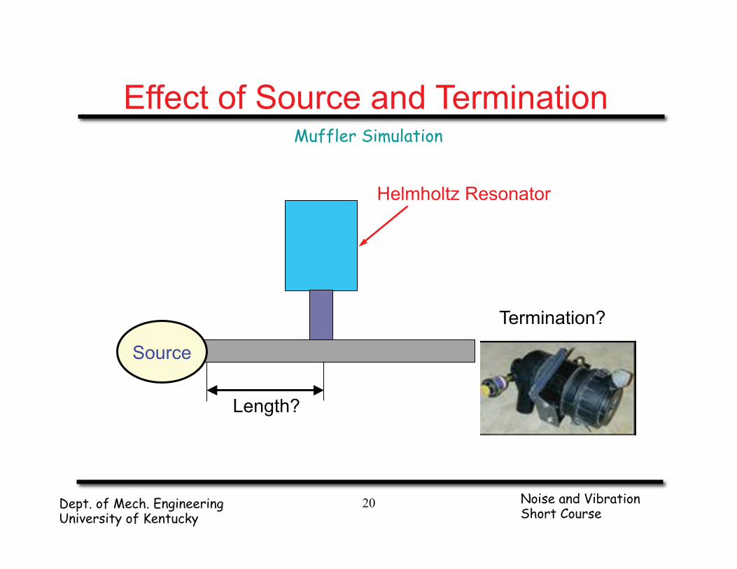
Effect of Source and Termination
Helmholtz Resonator
Source
Length?
Termination?

Muffler Simulation
Noise and Vibration Short Course
Dept. of Mech. Engineering University of Kentucky
21
-30
-20
-10
0
10
20
30
40
50
0 50 100 150 200 250 300 350 400
Frequency (Hz)
Inse
rtion
Los
s (d
B)
41 Inch Inlet61 Inch InletFiring Frequencies
Effect of Inlet Length

Muffler Simulation
Noise and Vibration Short Course
Dept. of Mech. Engineering University of Kentucky
22
Effect of Air Filter
-30
-20
-10
0
10
20
30
40
50
0 100 200 300 400
Frequency (Hz)
Inse
rtion
Los
s (d
B)
Helmholtz Resonator
Helmholtz Resonator + Air Filter
Firing Frequencies

Muffler Simulation
Noise and Vibration Short Course
Dept. of Mech. Engineering University of Kentucky
23
Overview
Transmission Loss
Insertion Loss
Source Impedance

Muffler Simulation
Noise and Vibration Short Course
Dept. of Mech. Engineering University of Kentucky
24
Sound Wave Reflections in Engines
Muffler
Engine
Waves leaving engine
Reflected from muffler
Reflected from engine
Waves leaving muffler
Reflected from open end
Reflected from muffler
Resonances can form in the exhaust and tail pipes as well as within the muffler.

Muffler Simulation
Noise and Vibration Short Course
Dept. of Mech. Engineering University of Kentucky
25
Sound Wave Reflections in Duct
Acoustic Source
Waves Leaving Source
Reflected from Attenuating Element
Reflected from Source
Attenuating Element (i.e. Load)
Acoustic Source
Waves Leaving Source
Reflected from Attenuating Element
Reflected from Source
Attenuating Element (i.e. Load)

Muffler Simulation
Noise and Vibration Short Course
Dept. of Mech. Engineering University of Kentucky
26
Physical Meaning of Circuit Analogy
Source Load
A B
x=0
k
c m
pL
ps
uppz
Smkmjc
Szz
Lss
ms
−=
⎟⎠
⎞⎜⎝
⎛⎟⎠
⎞⎜⎝
⎛ −+
==
ω

Muffler Simulation
Noise and Vibration Short Course
Dept. of Mech. Engineering University of Kentucky
27
Equivalent Circuit Analogy
Source Zs , ps
ps pL
Load ZL, pL
zs
zL L
L
Ls
szp
zzp
=+
Muffler Simulation
Noise and Vibration Short Course
Dept. of Mech. Engineering University of Kentucky
28
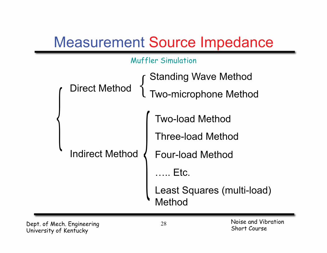
Direct Method
Indirect Method
{{ Standing Wave Method
Two-microphone Method
Two-load Method
Three-load Method
Four-load Method
….. Etc.
Least Squares (multi-load) Method
{
Measurement Source Impedance

Muffler Simulation
Noise and Vibration Short Course
Dept. of Mech. Engineering University of Kentucky
29
Microphones
Primary Source
External Source
Intake Pipe
Microphones
Primary Source
External Source
Intake Pipe
Standing Wave Method
Two-microphone Method
Measurement Direct Method

Muffler Simulation
Noise and Vibration Short Course
Dept. of Mech. Engineering University of Kentucky
30
Source p’s, Z’s
pZpZ
)pp(ZZZ
LLLL
LLLLs
1221
2121
−
−=
pZpZ)ZZ(pp
pLLLL
LLLLs
1221
2121
−
−=
where: ZL1, ZL2 — load Impedance for tube lengths L1, L2
pL1, pL2 — complex sound pressure for tube lengths L1, L2
Li (i = 1,2)
Source ps, Zs Load pLi, ZLi
Engine
Measurement Two-Load Method

Muffler Simulation
Noise and Vibration Short Course
Dept. of Mech. Engineering University of Kentucky
31
Li (i = 1,2,…,n)
Source ps, Zs Load pLi, ZLi
Engine
2
2
∑
∑
<
<
−
⎟⎟
⎠
⎞
⎜⎜
⎝
⎛
−
−⋅−−
=
jiLL
ji LL
LLLL
s
ji
ji
ji
ji
VV
VV
ppVV
Z
where: ZLi — load impedance for tube length Li
pLi — complex sound pressure for tube length Li
VLi — volume velocity for tube length Li : VLi = pi / ZLi
)(1
1∑=
+=
n
i L
LSLs
i
ii
ZZZp
np
Measurement Least Squares Method

Muffler Simulation
Noise and Vibration Short Course
Dept. of Mech. Engineering University of Kentucky
32
Prediction of IL
), ZC, D, Zf ( A, B, IL rs=
⎥⎦
⎤⎢⎣
⎡
DCBA
12”
Source Zs , ps
5”
Zr
Load ZL, pL
Expansion Chamber
φ1.5”
6”
φ 6”

Muffler Simulation
Noise and Vibration Short Course
Dept. of Mech. Engineering University of Kentucky
33
Insertion Loss Prediction
-30
-20
-10
0
10
20
30
40
50
60
0 200 400 600 800 1000Frequency (Hz)
IL (d
B)
Actual source impedancePressure source (Zs=0)Velocity source (Zs=infinite)Anechoic source (Zs=rho*c)

Muffler Simulation
Noise and Vibration Short Course
Dept. of Mech. Engineering University of Kentucky
34
Four tube lengths:
6”, 13”, 18” and 25”
Test Case Engine Intake

Muffler Simulation
Noise and Vibration Short Course
Dept. of Mech. Engineering University of Kentucky
35
Measured Source Impedance
-5-4-3-2-1012345
0 200 400 600 800 1000Frequency (Hz)
Z s /
Z 0
RealImaginary
Muffler Simulation
Noise and Vibration Short Course
Dept. of Mech. Engineering University of Kentucky
36
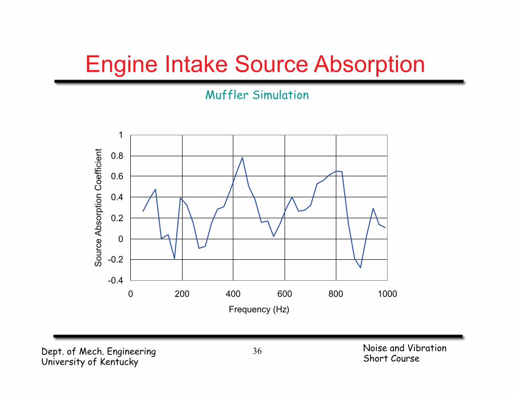
Engine Intake Source Absorption
-0.4
-0.2
0
0.2
0.4
0.6
0.8
1
0 200 400 600 800 1000
Frequency (Hz)
Sou
rce
Abs
orpt
ion
Coe
ffici
ent

Muffler Simulation
Noise and Vibration Short Course
Dept. of Mech. Engineering University of Kentucky
37
Engine Exhaust
Layout 6 cylinder, 4 stroke Fuel Diesel Exhaust Diameter 4 inches Exhaust Temperature Around 420°C Exhaust Flow Rate 0.12 Mach Test RPM 2400 Test Output Torque Around 500 N·m
Pressure Sensors
Reference Accelerometer

Muffler Simulation
Noise and Vibration Short Course
Dept. of Mech. Engineering University of Kentucky
38
Source Impedance Real Part
-5
0
5
10
15
0 300 600 900 1200 1500
Sou
rce
Impe
danc
e (R
e)
Frequency (Hz)
2-Load
Wave Decomposition

Muffler Simulation
Noise and Vibration Short Course
Dept. of Mech. Engineering University of Kentucky
39
Tested Results Imaginary Part
-10
-5
0
5
10
0 300 600 900 1200 1500
Sou
rce
Impe
danc
e (Im
)
Frequency (Hz)
2-Load
Wave Decomposition

Muffler Simulation
Noise and Vibration Short Course
Dept. of Mech. Engineering University of Kentucky
40
IL Prediction Muffler Design
Two cross-flow chambers
Helmholtz resonator tuned to the firing frequency
0
20
40
60
80
100
0 500 1000 1500
Tran
smis
sion
Los
s (d
B)
Frequency (Hz)
Tuned to 120 Hz

Muffler Simulation
Noise and Vibration Short Course
Dept. of Mech. Engineering University of Kentucky
41
IL Prediction Comparison
0
20
40
60
80
100
0 300 600 900 1200 1500
Inse
rtion
Los
s (d
B)
Frequency (Hz)
Anechoic source
Measured source impedance

Muffler Simulation
Noise and Vibration Short Course
Dept. of Mech. Engineering University of Kentucky
42
Summary
Transmission loss is a function of the silencer alone.
Transmission loss can be measured using the two-load or two-source method.
Insertion loss includes source and termination effects.
Source impedance should be measured.