measurement of instantaneous shaft speed by advanced
TRANSCRIPT
HAL Id: hal-00661222https://hal.archives-ouvertes.fr/hal-00661222
Submitted on 18 Jan 2012
HAL is a multi-disciplinary open accessarchive for the deposit and dissemination of sci-entific research documents, whether they are pub-lished or not. The documents may come fromteaching and research institutions in France orabroad, or from public or private research centers.
L’archive ouverte pluridisciplinaire HAL, estdestinée au dépôt et à la diffusion de documentsscientifiques de niveau recherche, publiés ou non,émanant des établissements d’enseignement et derecherche français ou étrangers, des laboratoirespublics ou privés.
Measurement of instantaneous shaft speed by advancedvibration signal processing - application to wind turbine
gearboxRadoslaw Zimroz, Jacek Urbanek, Tomash Barszcz, Walter Bartelmus, Fabien
Millioz, Nadine Martin
To cite this version:Radoslaw Zimroz, Jacek Urbanek, Tomash Barszcz, Walter Bartelmus, Fabien Millioz, et al.. Mea-surement of instantaneous shaft speed by advanced vibration signal processing - application to windturbine gearbox. MTA Review / Military Technical Academy Review, Military Technical AcademyPublishing House, 2011, 18 (4), pp.701-712. �hal-00661222�
Metrol. Meas. Syst., Vol. XVIII (2011), No. 4, pp. 701-712
________________________________________________________________________________________________________________________________________________________________________________ Article history: received on July 27, 2011; accepted on Nov. 21, 2011; available online on Dec. 12, 2011.
METROLOGY AND MEASUREMENT SYSTEMS
Index 330930, ISSN 0860-8229 www.metrology.pg.gda.pl
MEASUREMENT OF INSTANTANEOUS SHAFT SPEED BY ADVANCED VIBRATION SIGNAL PROCESSING - APPLICATION TO WIND TURBINE GEARBOX Radosław Zimroz1), Jacek Urbanek2), Tomasz Barszcz2), Walter Bartelmus1), Fabien Millioz 3), Nadine Martin3) 1) Diagnostics and Vibro-Acoustics Science Laboratory Pl Teatralny 2, 50-051, Wroclaw, Poland 2) AGH University of Science and Technology, Al. A. Mickiewicza 30, 30-059 Kraków, Poland (� [email protected]) 3) Département des Images et des Signaux BP 46 - 961, rue de la Houille Blanche 38402 Saint Martin d'Hères Cedex
Abstract
Condition monitoring of machines working under non-stationary operations is one of the most challenging problems in maintenance. A wind turbine is an example of such class of machines. One of effective approachesmay be to identify operating conditions and investigate their influence on used diagnostic features. Commonly used methods based on measurement of electric current, rotational speed, power and other process variables require additional equipment (sensors, acquisition cards) and software. It is proposed to use advanced signal processing techniques for instantaneous shaft speed recovery from a vibration signal. It may be used instead of extra channels or in parallel as signal verification.
Keywords: speed tracking, speed estimation, instantaneous frequency, spectrogram, wind turbines.
© 2011 Polish Academy of Sciences. All rights reserved
1. Introduction
Condition monitoring of rotating machines (gearboxes, rolling element bearings) via vibration analysis is a well-recognized and effective approach. However, in some cases (wind turbines, mining machines, ships, helicopters etc.), the machines work under non-stationary operating conditions (load and speed variation), that often require specific signal processing and pattern recognition suitable for time varying systems [1-9]. The wind turbine is a great example of such class of machines [10-14]. As it was suggested by [3, 13, 15], one of the effective approaches may be to identify the operating conditions and investigate their influence on diagnostic features used. In such a case, identification of the operating condition variations (i.e. external load or rotational speed of the input shaft in the gearbox) becomes one of the key problems.
Commonly used methods for operating conditions description are based on the measurement of electric current, rotational speed, power and other process variables and require additional equipment (sensors, acquisition cards) and software [16]. As it will be shown later, speed measurement by tachometer signal processing is sensitive to some disturbances (in case of lost samples, or if some artefacts appear in the measurement).
In this paper, the authors propose to use advanced signal processing techniques for instantaneous shaft speed recovery from the vibration signal. They may be used instead of an extra speed measurement channel or in parallel as signal verification.
R. Zimroz, J. Urbanek, et al.: MEASUREMENT OF INSTANTANEOUS SHAFT SPEED BY ADVANCED VIBRATION SIGNAL…
One of the most natural approaches is to identify the shaft rotational speed by estimation of the instantaneous frequency of the signal component that depends on the input speed. Usually Instantaneous Mesh Frequency (IMF) is chosen, due to relatively significant energy of the gear mesh characteristic component. Therefore, by IMF estimation it is possible to recalculate the input shaft speed. Problems of the Instantaneous Frequency (IF) [17, 18] estimation and instantaneous phase [19, 20] estimation are fundamental in signal processing. There are a few interesting approaches successfully applied in condition monitoring as the Hilbert transform [10, 21-23], time-scale techniques [24, 25], time-frequency techniques [26-28], Teager-Kaiser [29], Harmonic Decomposition [30], techniques based on polynomial modeling [31] etc.
The proposed method of speed estimation is based on vibration signal processing in the time-frequency domain. The basic idea is to detect a component in the time-frequency space and re-calculate frequency to speed. In order to make the procedure robust one should identify several mesh frequencies, normalize and average the results.
The paper is organized as follows. Chapter 2 contains a description of the wind turbine selected for the experiment including basic operational parameters, the kinematics chain and characteristic frequencies. Chapter 3 introduces the non-stationary operating conditions of the wind turbines. In the 4th chapter the vibration signal generated by the wind turbine is described together with its susceptibility to the variable operating conditions. The 5th chapter introduces the speed estimation method used in the experiment. The results obtained with the described method are presented in chapter 6. 2. Wind turbine gearbox – object description The wind turbine selected for the experiment is the one of the most commonly used turbines for a nominal electric power around 1000 kW. The basic operating data are presented in Table 1.
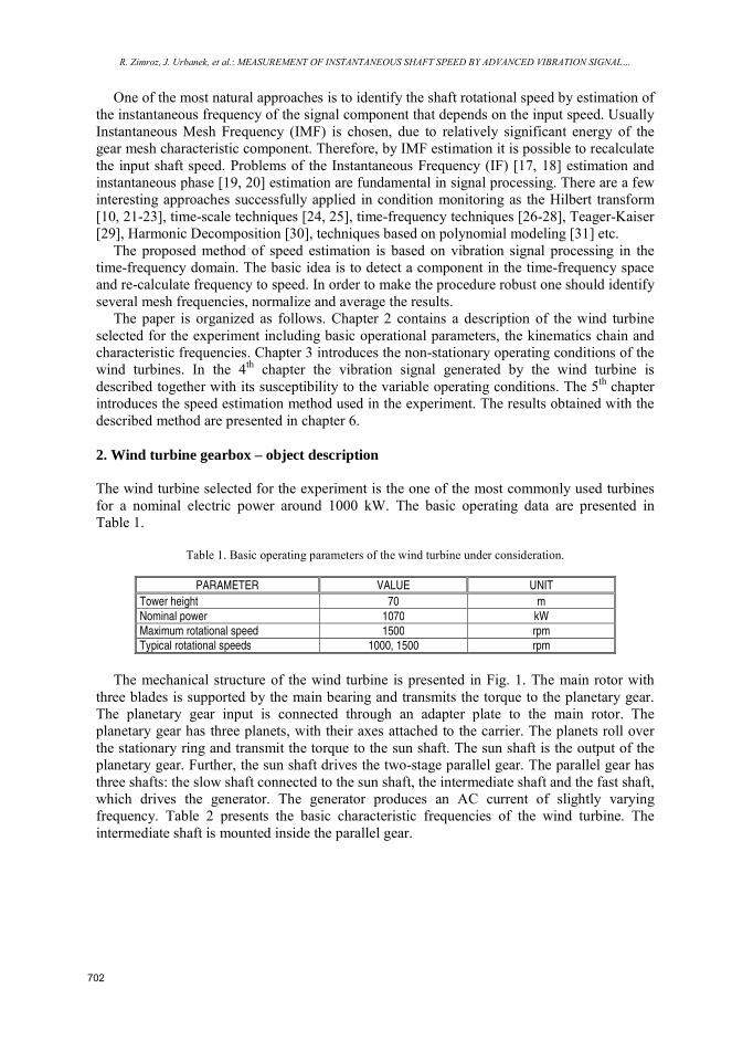
Table 1. Basic operating parameters of the wind turbine under consideration.
PARAMETER VALUE UNIT
Tower height 70 m
Nominal power 1070 kW Maximum rotational speed 1500 rpm Typical rotational speeds 1000, 1500 rpm
The mechanical structure of the wind turbine is presented in Fig. 1. The main rotor with
three blades is supported by the main bearing and transmits the torque to the planetary gear. The planetary gear input is connected through an adapter plate to the main rotor. The planetary gear has three planets, with their axes attached to the carrier. The planets roll over the stationary ring and transmit the torque to the sun shaft. The sun shaft is the output of the planetary gear. Further, the sun shaft drives the two-stage parallel gear. The parallel gear has three shafts: the slow shaft connected to the sun shaft, the intermediate shaft and the fast shaft, which drives the generator. The generator produces an AC current of slightly varying frequency. Table 2 presents the basic characteristic frequencies of the wind turbine. The intermediate shaft is mounted inside the parallel gear.
702
Metrol. Meas. Syst., Vol. XVIII (2011), No. 4, pp. 701-712
Gondola
Rotor
Generator
Parallel
gear
Planetary
Gear
Main bearing
Pedestal (on top of the tower)
A1 A2
A3 A4
A5 A6
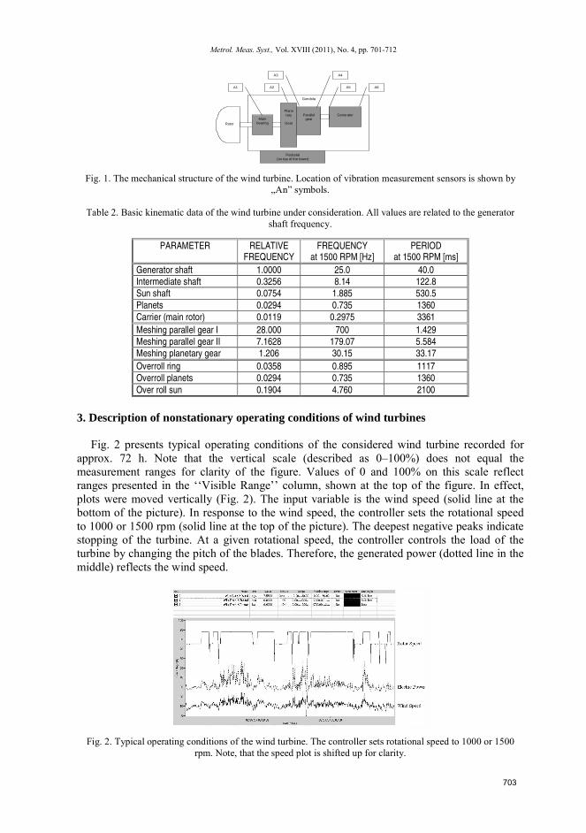
Fig. 1. The mechanical structure of the wind turbine. Location of vibration measurement sensors is shown by „An” symbols.
Table 2. Basic kinematic data of the wind turbine under consideration. All values are related to the generator
shaft frequency.
PARAMETER RELATIVE FREQUENCY
FREQUENCY at 1500 RPM [Hz]
PERIOD at 1500 RPM [ms]
Generator shaft 1.0000 25.0 40.0 Intermediate shaft 0.3256 8.14 122.8 Sun shaft 0.0754 1.885 530.5
Planets 0.0294 0.735 1360
Carrier (main rotor) 0.0119 0.2975 3361
Meshing parallel gear I 28.000 700 1.429 Meshing parallel gear II 7.1628 179.07 5.584 Meshing planetary gear 1.206 30.15 33.17
Overroll ring 0.0358 0.895 1117
Overroll planets 0.0294 0.735 1360
Over roll sun 0.1904 4.760 2100
3. Description of nonstationary operating conditions of wind turbines
Fig. 2 presents typical operating conditions of the considered wind turbine recorded for approx. 72 h. Note that the vertical scale (described as 0–100%) does not equal the measurement ranges for clarity of the figure. Values of 0 and 100% on this scale reflect ranges presented in the ‘‘Visible Range’’ column, shown at the top of the figure. In effect, plots were moved vertically (Fig. 2). The input variable is the wind speed (solid line at the bottom of the picture). In response to the wind speed, the controller sets the rotational speed to 1000 or 1500 rpm (solid line at the top of the picture). The deepest negative peaks indicate stopping of the turbine. At a given rotational speed, the controller controls the load of the turbine by changing the pitch of the blades. Therefore, the generated power (dotted line in the middle) reflects the wind speed.
Fig. 2. Typical operating conditions of the wind turbine. The controller sets rotational speed to 1000 or 1500 rpm. Note, that the speed plot is shifted up for clarity.
703
R. Zimroz, J. Urbanek, et al.: MEASUREMENT OF INSTANTANEOUS SHAFT SPEED BY ADVANCED VIBRATION SIGNAL…
4. Experiment Description. Preliminary signal investigations
The data acquisition system had the following features: – 6 vibration channels (accelerometers) – 25 kHz sampling frequency in each channel – 2 process channels: wind speed and generator power
The important factor for analysis of the turbine is that the power is changing very quickly. There were records, where during one 40s sampling session the power changed more than 50% of the range. This certainly had an impact on the dynamic state, making the use of standard vibration analysis techniques harder to apply.
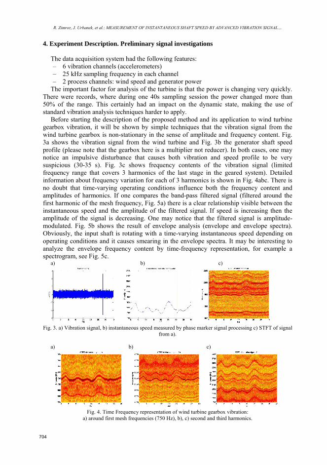
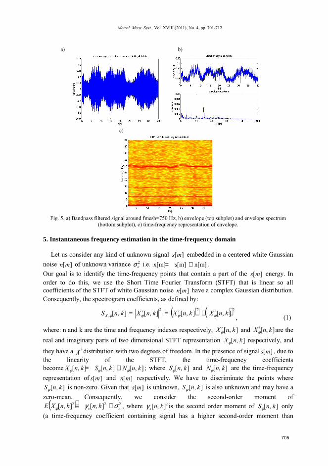
Before starting the description of the proposed method and its application to wind turbine gearbox vibration, it will be shown by simple techniques that the vibration signal from the wind turbine gearbox is non-stationary in the sense of amplitude and frequency content. Fig. 3a shows the vibration signal from the wind turbine and Fig. 3b the generator shaft speed profile (please note that the gearbox here is a multiplier not reducer). In both cases, one may notice an impulsive disturbance that causes both vibration and speed profile to be very suspicious (30-35 s). Fig. 3c shows frequency contents of the vibration signal (limited frequency range that covers 3 harmonics of the last stage in the geared system). Detailed information about frequency variation for each of 3 harmonics is shown in Fig. 4abc. There is no doubt that time-varying operating conditions influence both the frequency content and amplitudes of harmonics. If one compares the band-pass filtered signal (filtered around the first harmonic of the mesh frequency, Fig. 5a) there is a clear relationship visible between the instantaneous speed and the amplitude of the filtered signal. If speed is increasing then the amplitude of the signal is decreasing. One may notice that the filtered signal is amplitude-modulated. Fig. 5b shows the result of envelope analysis (envelope and envelope spectra). Obviously, the input shaft is rotating with a time-varying instantaneous speed depending on operating conditions and it causes smearing in the envelope spectra. It may be interesting to analyze the envelope frequency content by time-frequency representation, for example a spectrogram, see Fig. 5c.
a) b) c)
Fig. 3. a) Vibration signal, b) instantaneous speed measured by phase marker signal processing c) STFT of signal
from a).
a) b) c)
Fig. 4. Time Frequency representation of wind turbine gearbox vibration:
a) around first mesh frequencies (750 Hz), b), c) second and third harmonics.
704
Metrol. Meas. Syst., Vol. XVIII (2011), No. 4, pp. 701-712
a) b)
c)
Fig. 5. a) Bandpass filtered signal around fmesh=750 Hz, b) envelope (top subplot) and envelope spectrum
(bottom subplot), c) time-frequency representation of envelope. 5. Instantaneous frequency estimation in the time-frequency domain
Let us consider any kind of unknown signal ][ms embedded in a centered white Gaussian noise ][mn of unknown variance 2
nσ i.e. n[m]s[m]x[m] += . Our goal is to identify the time-frequency points that contain a part of the ][ms energy. In order to do this, we use the Short Time Fourier Transform (STFT) that is linear so all coefficients of the STFT of white Gaussian noise ][mn have a complex Gaussian distribution. Consequently, the spectrogram coefficients, as defined by:
( ) ( )222
, ],[],[],[],[ knXknXknXknS irrX φφφφ +== , (1)
where: n and k are the time and frequency indexes respectively, ],[ knX rφ and ],[ knX i
φ are the real and imaginary parts of two dimensional STFT representation ],[ knXφ respectively, and
they have a 2χ distribution with two degrees of freedom. In the presence of signal ][ms , due to the linearity of the STFT, the time-frequency coefficients become ],[],[],[ knNknSknX φφφ += ; where ],[ knSφ and ],[ knNφ are the time-frequency representation of ][ms and ][mn respectively. We have to discriminate the points where
],[ knSφ is non-zero. Given that ][ms is unknown, ],[ knSφ is also unknown and may have a zero-mean. Consequently, we consider the second-order moment of
( ) 222 ],[],[ ns knknXE σγφ += , where 2],[ knsγ is the second order moment of ],[ knSφ only (a time-frequency coefficient containing signal has a higher second-order moment than
705
R. Zimroz, J. Urbanek, et al.: MEASUREMENT OF INSTANTANEOUS SHAFT SPEED BY ADVANCED VIBRATION SIGNAL…
coefficients containing noise only). The distribution of the second-order moment of a time-frequency coefficients containing signal is unknown. However, the distribution of the second-order moment of points containing noise only is known and is a 2χ with two degrees of freedom. Consequently, we can apply a 2-hypothesis test, namely a Neyman-Pearson test, which allows us to get a threshold 2
ntσ
given a chosen false alarm probability afp
( )
annfptknNobt => 22
2],[Pr / σφσ , (2)
( )12 ln2
−=afn
pt nσσ , (3)
where ( )xln is the natural logarithm. All time-frequency coefficients whose second-order moment is higher than this threshold will be detected as a signal. The threshold 2
ntσ depends
on the chosen false alarm probability, and the noise level 2nσ , which has to be estimated.
To estimate the noise level, a Maximum Likelihood (ML) estimator is unbiased and optimal in case of noise only. When a signal ][ms is present, the estimator becomes biased. The signal to segment results in an overestimation of the noise level. Unfortunately, given than this signal is unknown, its time-frequency location is also unknown. The idea is consequently to use an iterative algorithm: the noise level, at first overestimated, permits the determination of a first threshold. Some points containing the signal are therefore detected. The next iterations re-estimate the noise level only in points that are not detected as containing a signal. The noise level is less overestimated, leading to a lower detection threshold, and thus new points containing the signal are detected.
A stop criterion is required to determine if all non-detected points are noise only, in other words if all non-detected points have a complex Gaussian distribution. To that end, we use the spectral kurtosis [26, 27] )(zSK which is the kurtosis definition for a complex random variable z:
( )( )
2 *2
2*( ) 2.
E z zSK z
E zz= - (4)
As a real Gaussian random variable has the particularity to have a kurtosis equal to zero, complex Gaussian variables have a spectral kurtosis equal to zero. Consequently the algorithm stops when the spectral kurtosis of the non-detected points becomes smaller than a threshold SKt , considering than the remaining points have a complex Gaussian distribution.
In summary, the time-frequency segmentation used in the paper is an iterative process: at each iteration, the noise level is overestimated due to the presence of signal; then this noise level permits the detection of some signal points. A region growing algorithm is applied to extract a pattern from these detected points. The iterations are stopped when the remaining points have a Gaussian complex distribution, in other words when the spectral kurtosis of these points becomes smaller than the threshold SKt .
We now apply this general segmentation algorithm to the particular case of wind turbine gearbox signals. First, we have to choose the STFT parameters. A Hann window of 1023 points, an overlap of 511 points and 8192 frequencies is chosen, giving acceptable time-frequency resolution of the modulated frequencies. Then, the STFT is divided into several frequency bands, each one including only one frequency modulation. Finally, we have to define segmentation parameters
afp , candp and KSt The goal is to detect the frequency modulation, which is embedded in quite low noise level, in a single continuous pattern.
706
Metrol. Meas. Syst., Vol. XVIII (2011), No. 4, pp. 701-712
Consequently, a high probability of false alarm is sufficient to detect the signal. We set 1.0=
afp . To get only one pattern, the proportion of candidates should be low to avoid creating useless new patterns. Finally, we wish to stop the algorithm as soon as the signal is detected: a high spectral kurtosis threshold is chosen, 2=SKt . 6. Results of instantaneous shaft speed (ISS) estimation
The proposed method was able to extract speed fluctuations of a wind turbine using vibration signals. It could overcome significant amplitude modulation and relatively low SNR. Because all procedures are being calculated in the time-frequency domain, it is possible to estimate the speed with much greater volatility than with other methods.
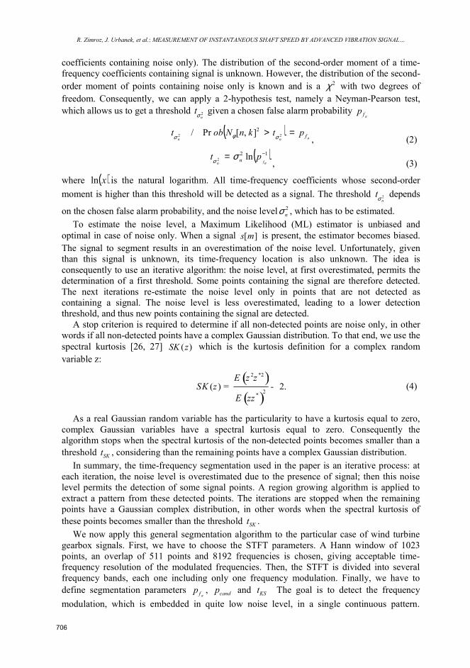
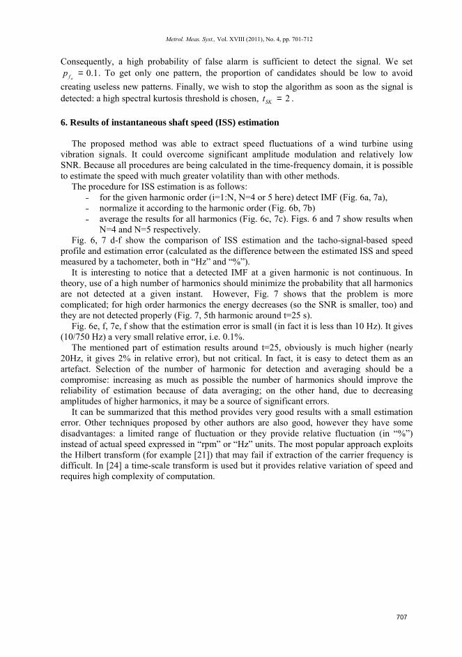
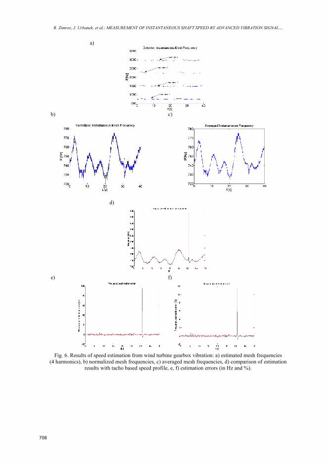
The procedure for ISS estimation is as follows: ˗ for the given harmonic order (i=1:N, N=4 or 5 here) detect IMF (Fig. 6a, 7a), ˗ normalize it according to the harmonic order (Fig. 6b, 7b) ˗ average the results for all harmonics (Fig. 6c, 7c). Figs. 6 and 7 show results when
N=4 and N=5 respectively. Fig. 6, 7 d-f show the comparison of ISS estimation and the tacho-signal-based speed
profile and estimation error (calculated as the difference between the estimated ISS and speed measured by a tachometer, both in “Hz” and “%”).
It is interesting to notice that a detected IMF at a given harmonic is not continuous. In theory, use of a high number of harmonics should minimize the probability that all harmonics are not detected at a given instant. However, Fig. 7 shows that the problem is more complicated; for high order harmonics the energy decreases (so the SNR is smaller, too) and they are not detected properly (Fig. 7, 5th harmonic around t=25 s).
Fig. 6e, f, 7e, f show that the estimation error is small (in fact it is less than 10 Hz). It gives (10/750 Hz) a very small relative error, i.e. 0.1%.
The mentioned part of estimation results around t=25, obviously is much higher (nearly 20Hz, it gives 2% in relative error), but not critical. In fact, it is easy to detect them as an artefact. Selection of the number of harmonic for detection and averaging should be a compromise: increasing as much as possible the number of harmonics should improve the reliability of estimation because of data averaging; on the other hand, due to decreasing amplitudes of higher harmonics, it may be a source of significant errors.
It can be summarized that this method provides very good results with a small estimation error. Other techniques proposed by other authors are also good, however they have some disadvantages: a limited range of fluctuation or they provide relative fluctuation (in “%”) instead of actual speed expressed in “rpm” or “Hz” units. The most popular approach exploits the Hilbert transform (for example [21]) that may fail if extraction of the carrier frequency is difficult. In [24] a time-scale transform is used but it provides relative variation of speed and requires high complexity of computation.
707
R. Zimroz, J. Urbanek, et al.: MEASUREMENT OF INSTANTANEOUS SHAFT SPEED BY ADVANCED VIBRATION SIGNAL…
a)
b) c)
d)
e) f)
Fig. 6. Results of speed estimation from wind turbine gearbox vibration: a) estimated mesh frequencies
(4 harmonics), b) normalized mesh frequencies, c) averaged mesh frequencies, d) comparison of estimation results with tacho based speed profile, e, f) estimation errors (in Hz and %).
708

Metrol. Meas. Syst., Vol. XVIII (2011), No. 4, pp.701-712
a)
b) c)
d)
e) f)
Fig. 7. Results of speed estimation from wind turbine gearbox vibration: a) estimated mesh frequencies
(5 harmonics), b) normalized mesh frequencies, c) averaged mesh frequencies, d) comparison of estimation results with tacho based speed profile, e, f ) estimation errors (in Hz and %).
7. Conclusion
In the paper, the application of instantaneous shaft speed measurement by instantaneous frequency estimation of the vibration signal is considered. The methodology developed
709
R. Zimroz, J. Urbanek, et al.: MEASUREMENT OF INSTANTANEOUS SHAFT SPEED BY ADVANCED VIBRATION SIGNAL…
initially for mining machines has been successfully tested here for the wind turbine. It has been shown that the variability of operating conditions is large and thus in the vibration signal, its frequency contents and amplitudes of characteristic components are time varying too. The influence of operating conditions and their impact on the vibration signal and further feature extraction procedures and amplitudes of these features are crucial for this kind of machines and it is formulated for the first time in the literature. The estimated instantaneous speed may be used instead of additional channels commonly used for process (speed, current, etc.) variable acquisitions or it may be treated as a verification of measurements that may be corrupted by impulsive, unexpected disturbances. It is worth to mention that estimation accuracy is very good and the averaged estimation error is small. Acknowledgements
Paper is financially supported by the State Committee for Scientific Research in 2010 - 2013 as research project N N504 147838 (AGH, WUT). References
[1] Stander, C.J., Heyns, P.S., Schoombie, W. (2002). Using vibration monitoring for local fault detection on
gears operating under fluctuating load conditions. Mechanical Systems and Signal Processing, 16(6), 1005-1024.
[2] Cempel, Cz., Tabaszewski M. (2007). Multidimensional condition monitoring of machines in nonstationary operation. Mechanical Systems and Signal Processing, 21, 1233-1241.
[3] Bartelmus, W., Zimroz, R. (2009). A new feature for monitoring the condition of gearboxes in non-stationary operating conditions. Mechanical Systems and Signal Processing, 23(5), 1528-1534.
[4] Grzadziela, A. (2007). An analysis of possible assessment of hazards to ship shaft line, resulting from impulse load. Polish Maritime Research, 14(3), 12-20.
[5] Bartelmus, W., Chaari, F., Zimroz, R., Haddar, M. (2010). Modelling of gearbox dynamics under time varying non-stationary operation for distributed fault detection and diagnosis. European Journal of Mechanics - A/Solids, 29, 637-646.
[6] Stander, C.J., Heyns, P.S., Schoombie, W. (2002). Using vibration monitoring for local fault detection on gears operating under fluctuating load conditions. Mechanical Systems and Signal Processing, 16(6), 1005-1024.
[7] Zhan, Y., Makis, Y., Jardine, A.K.S. (2004). Adaptive state detection of gearboxes under varying load conditions based on parametric modelling. Mechanical Systems and Signal Processing, 20(1), 188-221.
[8] Timusk, M., Lipsett, M., Mechefske, C.K. (2008). Fault detection using transient machine signals. Mechanical Systems and Signal Processing, 23, 1724-1749.
[9] Baydar, N., Ball, A. (2002). Detection of gear deterioration under varying load conditions by using the instantaneous power spectrum. Mechanical Systems and Signal Processing, 14(6), 907-921.
[10] Urbanek, J., Barszcz, T., Sawalhi, N., Randall, R.B. (2011). Comparison of amplitude based and phase based methods for speed tracking in application to wind turbines. Metrology and Measurement Systems, 18(2), 295-304.
[11] Barszcz, T. Randall, R.B. (2009). Application of spectral kurtosis for detection of a tooth crack in the planetary gear of a wind turbine. Mechanical Systems And Signal Processing, 23(4), 1352-1365.
[12] Barszcz, T. (2004). Proposal of new method of mechanical vibration measurement. Metrology and Measurement Systems, 11(4), 409-421.
[13] Barszcz, T., Bielecka, M., Bielecki, A., Wójcik, M. (2011). Wind turbines states classification by a fuzzy-ART neural network with a stereographic projection as a signal normalization. Lecture Notes in Computer Science, 6594/2011, 225-234.
710
Metrol. Meas. Syst., Vol. XVIII (2011), No. 4, pp. 701-712
[14] Barszcz, T., Bielecki, A., Wójcik, M. (2010). ART-type artificial neural networks applications for classification of operational states in wind turbines. Lecture Notes in Computer Science, 6114/2010, 11-18.
[15] Bartelmus, W, Zimroz, R (2009). Vibration condition monitoring of planetary gearbox under varying external load. Mechanical Systems and Signal Processing, 23(1), 246-257.
[16] Coats, M.D., Sawalhi, N., Randall, R.B. (23-25 Nov 2009). Extraction of tach information from a vibration signal for improved synchronous averaging. Proceedings of Acoustics. Adelaide. Australia.
[17] Boashash, B. (1992). Estimating and Interpreting The Instantaneous Frequency of a Signal-Part 1: Fundamentals. Proceedings of the IEEE, 80(4), 520-538.
[18] Boashash, B. (1992). Estimating and Interpreting the Instantaneous Frequency of a Signal-Part 2: Algorithms and Applications. Proceedings of the IEEE, 80(4), 540-568.
[19] Borkowski, D. (2005). On-line instantaneous frequency estimation and voltage/current coherent resampling metod. Metrology and Measurement Systems, 12(1), 59-75.
[20] Sedlacek, M., Krumpholc, M. (2005). Digital measurement of phase difference - a comparative study of DSP algorithms. Metrology and Measurement Systems, 12(4), 427-449.
[21] Bonnardot, F., El Badaoui, M., Randall, R.B., Danie`re, J., Guillet, F. (2005). Use of the acceleration signal of a gearbox in order to perform angular resampling (with limited speed fluctuation). Mechanical Systems and Signal Processing, 19, 766-785.
[22] Wallace, D.A., Darlow, M.S. (1988). Hilbert transform techniques for measurement of transient gear speeds. Mechanical Systems and Signal Processing, 2(2), 187-194.
[23] Combet, F., Gelman, L. (2007). An automated methodology for performing time synchronous averaging of a gearbox signal without speed sensor. Mechanical Systems and Signal Processing, 21(6), 2590-2606.
[24] Combet, F., Zimroz, R., (2009). A new method for the estimation of the instantaneous speed relative fluctuation in a vibration signal based on the short time scale transform. Mechanical Systems and Signal Processing, 23(4), 1382-139.
[25] Zimroz, R., Combet, F. (2006). Time varying outer load and speed estimation by vibration analysis - application to planetary gearbox diagnosis in a mining bucket wheel excavator. Diagnostics, 4, 7-14.
[26] Millioz, F., Martin N. (2006). Time-Frequency Segmentation for Engine Speed Monitoring. Proceedings of Thirteen International Congress on Sound and Vibration ICSV13, Vienna, Austria.
[27] Zimroz R., Millioz F., Martin N. (2010). A procedure of vibration analysis from planetary gearbox under non-stationary cyclic operations for instantaneous frequency estimation in time-frequency domain. Proceedings of Condition Monitoring, Stratford Upon Avon, UK.
[28] Proceedings of the IEEE. (1996). Special Issue on Time Frequency Analysis, 84(9), 1194-1345.
[29] Gryllias, K., Antoniadis, I. (2009). Application of the Energy operator separation algorithm (EOSA) for the instantaneous amplitude and Frequency calculation of nonlinear dynamic systems response. Proceedings of the ASME International Design Engineering Conference and Computers and Information in Engineering Conference IDECT/CIE, San Diego, USA.
[30] Christos, Y., Gryllias, K., Antoniadis, I. (2009). Instantaneous frequency in rotating machinery using a harmonic signal decomposition (HARD) parametric method. Proceedings of the ASME International Design Engineering Conference and Computers and Information in Engineering Conference IDECT/CIE, San Diego, USA.
[31] Jabloun, M., Martin, N., Leonard, F., Vieira, M. (2008). Estimation of the amplitude and the frequency of nonstationary short-time signals. Signal Processing, 88(7), 1636-1655.
711