me6000 sensor guide for megawin - meditech · 4 creating new protocol 13 5 signal calibration 17...
TRANSCRIPT

ME6000 Sensor guide for MegaWin
ME6000 Sensor guide for
Mega Electronics Ltd 2009
This manual is applicable to:
Mega Electronics Ltd reserves all rights to improve, change and modify the products and the contents of manuals without prior notice.
© Mega Electronics Ltd. 2008
Mega Electronics Ltd. Microkatu 1 P.O. Box 1199 FIN-70211 KUOPIO FINLAND
tel. +358 (0)17 581 7700 fax. +358 (0)17 580 0978 e-mail: [email protected] web: http://www.megaemg.com
1) ME6000 4-channel system revision MT-M6T4-0
2) ME6000 8-channel system revision MT-M6T8-0
3) ME6000 16-channel system revision MT-M6T16-0
4) ME4ISO Isolation Unit* revision MP-ISO4-1
*for detailed compatibility see separate ME4ISO Isolation Unit Device Manual
with MegaWin software versions 3.0 and onwards
N O TE !

Order code 800576-1.1
Mega Electronics Ltd 2009
!WARNING
IMPORTANT ! Before operating the device, please read this manual thoroughly and retain it for future reference. Caution. These statements identify conditions or practices that could result in damage to the equipment or other property. Warning. These statements identify conditions or practices that could result in personal injury or loss of life. Note. These statements identify condition or practices that could result in performance loss of the equipment or must be otherwise paid attention to. N O T
E !
!CAUTION

ME6000 Sensor guide for
Mega Electronics Ltd 2009
Table of contents
1 GETTING STARTED 7
1.1 HOW TO SEE THE AVAILABLE ME6000 SENSORS IN MEGAWIN 8
2 SIGNAL DEFINITION 9
3 CREATING NEW CONFIGURATION 11
4 CREATING NEW PROTOCOL 13
5 SIGNAL CALIBRATION 17
5.1 PREPARING ME6000 FOR CALIBRATION 17 5.2 CALIBRATION MEASUREMENT 19 5.3 CALIBRATION – CALCULATION OF GAIN AND OFFSET 20 5.4 SENDING CALIBRATION VALUES TO ME6000 22
6 GONIOMETER & TORSIOMETER SENSORS 23
6.1 GENERAL DESCRIPTION 23 6.1.1 Single axis goniometer 23 6.1.2 Twin axis goniometers 24 6.1.3 Single axis torsiometer 24
6.2 CONNECTING THE SENSOR 24 6.3 SIGNAL ADJUSTMENT 26 6.4 CLEANING 26 6.5 GENERAL INSTRUCTIONS 26
7 FOOT SWITCH SENSOR 27
7.1 GENERAL DESCRIPTION 27 7.2 CONNECTING THE SENSOR 27 7.3 SIGNAL ADJUSTMENT 28 7.4 CLEANING 28 7.5 GENERAL INSTRUCTIONS 28
8 INCLINOMETER SENSOR 29
8.1 GENERAL DESCRIPTION 29

Order code 800576-1.1
Mega Electronics Ltd 2009
8.2 CONNECTING THE SENSOR 29 8.3 SIGNAL ADJUSTMENT 30 8.4 CLEANING 30 8.5 GENERAL INSTRUCTIONS 30
9 ACCELEROMETER SENSOR 31
9.1 GENERAL DESCRIPTION 31 9.2 CONNECTING THE SENSOR 31 9.3 SIGNAL ADJUSTMENT 32 9.4 CLEANING 32 9.5 GENERAL INSTRUCTIONS 32
10 POLAR HEART RATE SENSOR SET 33
10.1 GENERAL DESCRIPTION 33 10.2 CONNECTING THE SENSOR 33 10.3 SIGNAL ADJUSTMENT 34 10.4 CLEANING 34 10.5 GENERAL INSTRUCTIONS 34
11 ECG SENSOR 35
11.1 GENERAL DESCRIPTION 35 11.2 CONNECTING THE SENSOR 35 11.3 SIGNAL ADJUSTMENT 36 11.4 CLEANING 36 11.5 GENERAL INSTRUCTIONS 36
12 LOAD CELL 37
12.1 GENERAL DESCRIPTION 37 12.2 CONNECTING THE SENSOR 37 12.3 SIGNAL ADJUSTMENT 37 12.4 CLEANING 37 12.5 GENERAL INSTRUCTIONS 38
13 GYRO SENSOR 39
13.1 GENERAL DESCRIPTION 39 13.2 CONNECTING THE SENSOR 39 13.3 SIGNAL ADJUSTMENT 39 13.4 CLEANING 40 13.5 GENERAL INSTRUCTIONS 40
14 GSR SENSOR 41
14.1 GENERAL DESCRIPTION 41 14.2 CONNECTING THE SENSOR 41

ME6000 Sensor guide for
Mega Electronics Ltd 2009
14.3 SIGNAL ADJUSTMENT 41 14.4 CLEANING 42 14.5 GENERAL INSTRUCTIONS 42
15 TIDAL VOLUME SENSOR 43
15.1 GENERAL DESCRIPTION 43 15.2 CONNECTING THE SENSOR 43 15.3 CLEANING 44 15.4 GENERAL INSTRUCTIONS 44
16 FORCE / PRESSURE SENSOR 45
16.1 GENERAL DESCRIPTION 45 16.2 CONNECTING THE SENSOR 45 16.3 SIGNAL ADJUSTMENT 46 16.4 CLEANING 46 16.5 GENERAL INSTRUCTIONS 46
17 MAINTENANCE AND SERVICE 47
17.1 CALIBRATION 47 17.2 CLEANING 47 17.3 GETTING ASSISTANCE 47
18 COMMENTS FOR USE 49

Order code 800576-1.1
7 Mega Electronics Ltd 2009
11 GGEETTTTIINNGG SSTTAARRTTEEDD This guide describes the procedure how you bring new sensor into use with the ME6000 device in MegaWin measuring system. The most commonly used ME6000 sensors are also described in this document. As the first step connect the sensor cable to the connector ch1 – ch2 (4 and 8 channel device) or to connector ch1 – ch4 (16 channel device). This guide describes the procedure assuming that the sensor (in focus) is connected into the channel 1.
80
039
7
ME6000
Sensor Ch1
Othersensors
Figure 1-1. Connecting the sensor cable to the ME6000 Biomonitor 8 ch Before you proceed, make sure that MegaWin is operating properly with ME6000 device. If needed, refer MegaWin user’s manual and ME6000 device manual. If the sensor is corresponding to some of predefined ME6000 sensors (signals) in MegaWin, you may enter to chapter 3 (Creating New Configuration). Predefined sensors (signals) are EMG, Goniometer, Accelerometer, Inclinometer, Polar interface, ECG, Torque and Gyrometer.
ME6000 Sensor guide for
Mega Electronics Ltd 2009 8
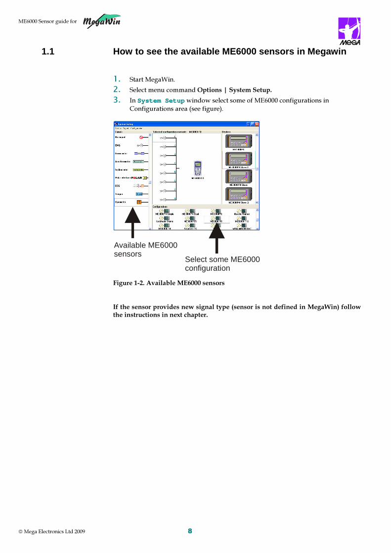
1.1 How to see the available ME6000 sensors in Mega win 1. Start MegaWin. 2. Select menu command Options | System Setup. 3. In SSyysstteemm SSeettuupp window select some of ME6000 configurations in
Configurations area (see figure).
Figure 1-2. Available ME6000 sensors If the sensor provides new signal type (sensor is not defined in MegaWin) follow the instructions in next chapter.
Select some ME6000 configuration
Available ME6000 sensors

Order code 800576-1.1
9 Mega Electronics Ltd 2009
22 SSIIGGNNAALL DDEEFFIINNIITTIIOONN In this guide we use Force sensor/signal as new example signal. 1. Select menu command Options | System Setup 2. In SSyysstteemm SSeettuupp window select some of ME6000 configurations in
Configurations area (see figure). 3. In SSyysstteemm SSeettuupp window select menu command Signal | New 4. SSiiggnnaall window will be displayed.
Figure 2-1. Signal window for definition 5. Input the name of your signal to NAME field. In our example the name is
“Force”. 6. In ICON field is shown the default sensor/signal symbol. 7. You can change signal symbol as follows:
- Double click ICON field - press Load from file button (in PPiiccttuurree eexxpplloorreerr ) - Browse to MegaWin signal image folder (as default it is located in C:\Program Files\MEGAWIN\Images\Signals ) - Select the desired signal file and press Open – press OK in PPiiccttuurree eexxpplloorreerr window
8. DO NOT CHANGE the SIGTYPE, which is given by MegaWin. 9. Input the unit of the signal. In our example the unit is “N” (=Newton). 10. FACTOR (=Gain) values should be 1. 11. RAWOFFS (=offset) value should be 0. 12. You do not need to change AVROFFS – ME6000 does not use this value. 13. ME6000 SENSOR must be Sensor. 14. Select ME6000 SENSOR number 1.

ME6000 Sensor guide for
Mega Electronics Ltd 2009 10
If you have several same type (for ex. Force) of sensors, you must define each sensor/signal (in the same way as explained here) and give own number for it (example Force1 : Sensor 1, Force 2 : Sensor 2, etc…
15. Example Signal definition (Force signal).
Figure 2-2. Example signal definition (Force) 16. Finally press OK. Now the new signal (example: Force) is available in the signal list to be used in Configurations.
Figure 2-3. New sensor/signal in signal list
N O T E!
New ME6000 sensor/signal

Order code 800576-1.1
11 Mega Electronics Ltd 2009
33 CCRREEAATTIINNGG NNEEWW CCOONNFFIIGGUURRAATTIIOONN The measurement configuration is the answer to the question “with which device and with which signals the measurement will be performed?”
Configuration contains the hardware definitions for the measurement.
1. Select menu command Options | System Setup 2. In SSyysstteemm SSeettuupp window select some of ME6000 configurations in
Configurations area (see figure). 3. In SSyysstteemm SSeettuupp window select menu command Configuration | New 4. Give the name for the configuration.
Figure 3-1. Configuration – name and description definition 5. Description is not mandatory. 6. Press OK . 7. Configuration content area is empty.
Figure 3-2. Configuration content area for new configuration
N O T E!

ME6000 Sensor guide for
Mega Electronics Ltd 2009 12
8. Drag the ME6000 device icon from device list to the Configuration content area.
Drag by pressing mouse left button on top of the icon – keep button pressed and move the icon. In the configuration content area - release mouse button.
Figure 3-3. Device icon dragged to the Configuration content area 9. Drag the signal icon (example: Force) from signal list to the Configuration
content area. Drag and drop as instructed in previous step to the channel 1 location.
Figure 3-4. Signal icon dragged to the Configuration content area Now the new configuration is ready to be selected for use in new protocol. This configuration appears also to the list of available configurations (at the bottom of the System Setup window).
If you have same type of sensor such as Force1, Force2 etc… you may use those just once in a configuration. For example Force1 to channel1, Force2 to channel2 etc… (NOT Force1 to channel1, Force1 to channel2)
N O T E!

Order code 800576-1.1
13 Mega Electronics Ltd 2009
44 CCRREEAATTIINNGG NNEEWW PPRROOTTOOCCOOLL The measurement configuration is the answer to the question “How measurement will be performed and in which form the data will be created?”
Protocol controls the measurement and defines the form (raw, averaged) of recorded data.
1. Press Protocol button in MMeeggaaWWiinn MMaaiinn window. 2. Press New button in PPrroottooccooll window. It starts the Protocol Editor wizard,
which guides you through the process of configuring the protocol.
Figure 4-1. Starting new protocol definition 3. Give protocol name (example : Force measurement), select Advanced protocol
and press Next button.
Figure 4-2. Protocol name and editor mode selection 4. Select the configuration (example: Force configuration) and press Next
button.
N O T E!

ME6000 Sensor guide for
Mega Electronics Ltd 2009 14
Figure 4-3. Selection of the configuration 5. Select body region (Example: General body) and press Next button.
Figure 4-4. Selection of body region 6. Select source(s) for the signal:
Figure 4-5. Selection of signal source

Order code 800576-1.1
15 Mega Electronics Ltd 2009
Press Select source… button. Select No name to be the signal name. Press OK button. Then press Next button. 7. Select measurement type On-line (real time measurement) and the protocol
component Raw free.
Figure 4-6. Selection of measurement type and protocol component 8. Press Pick to protocol button. 9. CCoommppoonneenntt pprrooppeerrttiieess of raw free are opened. Make the selections as
shown in the figure below. You only need to set total duration to be 3 min. Other setting may be as default.
Figure 4-7. Settings of the raw free component 10. Press OK button.

ME6000 Sensor guide for
Mega Electronics Ltd 2009 16
11. Finally press Finish button.
Figure 4-8. Completed protocol definition Now the new protocol is ready to be used in measurements. The protocol is available in the protocol list in the Protocol window.
Figure 4-9. New protocol shown in Protocol window

Order code 800576-1.1
17 Mega Electronics Ltd 2009
55 SSIIGGNNAALL CCAALLIIBBRRAATTIIOONN New sensor/signal must be calibrated with ME6000 before it can be used in real measurements in MegaWin. The goal of the calibration is to measure and calculate the correct gain and offset values for the signal and finally send them to ME6000 to be used during the measurement.
5.1 Preparing ME6000 for calibration Start MegaWin and ME6000. Make sure that ME6000 communicates with MegaWin. 1. Select menu command Options | System Setup 2. Select the ME6000 configuration which has made for new sensor/signal
(Example: Force configuration) and which will be used in calibration. 3. Press mouse right button on the ME6000 device icon in Selected configuration
contents area. 4. Select menu command Send calibration values.
Figure 5-1. Mouse right click at ME6000 icon. 5. The CCaalliibbrraattiioonn vvaalluueess window will be opened. 6. If the current gain and offset in the ME6000 differs from the values you are
going to send, continue in the next phase 7.
Figure 5-2. Calibration values window for sending calibration values to ME6000.

ME6000 Sensor guide for
Mega Electronics Ltd 2009 18
Otherwise you may close the window and move to next chapter 5.2 - Calibration measurement.
7. Select the new values from configuration you want to send.
Figure 5-3. Selection of the values to be sent to ME6000. 8. Then press button: 9. New calibration values are transferred to ME6000. “New calibration values set”
message indicates that ME6000 is ready to use these calibrated signals.
Figure 5-4. Message after sending values to ME6000. 10. Press OK button.
Figure 5-5. Calibration values window after sending values to ME6000. 11. Close the CCaalliibbrraattiioonn vvaalluueess window. 12. Make sure that the sensor cable is connected to ME6000 and it has attached
properly for the calibration measurement.

Order code 800576-1.1
19 Mega Electronics Ltd 2009
The ME6000 calibration protocol MUST be a RAW measurement. On-line measurement is recommended.
Previously, in chapter 4 we have defined raw protocol, which can be used in the calibration measurement.
5.2 Calibration measurement The purpose in the calibration measurement is to get two known signal levels (lower and higher) to the measured data. 1. Define the patient information for calibration measurement. Press Person
button in MMeeggaaWWiinn MMaaiinn window. Make the New person definition (see further information in MegaWin User’s manual). Close PPeerrssoonn window.
2. Press Measure button in MMeeggaaWWiinn MMaaiinn window. 3. Select protocol and person. (in example: Force measurement and Calibration
data).
Figure 5-6. Measure window 4. Press Run protocol button. 5. Start the measurement by pressing:
6. Measure the lower known signal level (MINIMUM) and press marker
(marker1). In our example we have NO weight on the sensor. 7. Measure the higher known signal level (MAXIMUM) and press marker
(marker2). In our example we have placed 20 kg weight on the sensor. 8. Repeat steps 6 – 7 for all signals need to be calibrated. 9. Stop and save the measurement. Event markers help you to locate the correct minimum and maximum levels for calibration.
N O TE !
N O TE !

ME6000 Sensor guide for
Mega Electronics Ltd 2009 20
Figure 5-7. The data of the calibration measurement
5.3 Calibration – calculation of gain and offset The purpose of calibration is to produce new Factor (Gain) and Raw offset (offset) values into channel’s DDeevviiccee--ssiiggnnaall--cchhaannnneell window in the SSyysstteemm sseettuupp. 1. Open the calibration measurement data to VViieeww window (see figure 5-7). 2. Select Cursor and move it using PPrreevviioouuss mmaarrkkeerr or NNeexxtt MMaarrkkeerr buttons
to the known MINIMUM level (marker 1) on the channel to be calibrated. If there is not a marker at that site then press the space key to lock the cursor.
3. Click the FFrreeeezzee CCuurrssoorr button, in the FFrreeeezzee cchhaannnneellss pop-up select the channels you wish to calibrate and click OK .
4. The SSttaattiissttiiccss window appears. Unlock the differential cursor using the space key and move it to the known MAXIMUM level (marker 2) of the channel. If there is not a marker at that site, then press the space key again to lock the cursor.
5. Double-click the box of the Y-dif value for the channel to be calibrated to open the CCaalliibbrraattiioonn window.
Figure 5-8. Activation of the calibration window
Double clickthis box

Order code 800576-1.1
21 Mega Electronics Ltd 2009
Figure 5-9. Calibration window 6. The Y-min and Y-Max fields are displaying the minimum and maximum levels.
Type the actual signal values in Actual Y-Min and Actual Y-Max field. Check Set zero.
Actual Y-Min is 0 N (no weight on the sensor) and Actual Y-Max is 196,2N (20 kg on the sensor).
Figure 5-10. Calibration window after new values given Set zero must be must be checked!
7. Click Calibrate to make the calibration. The new values are set in the channel’s
DDeevviiccee--ssiiggnnaall--cchhaannnneell window in the SSyysstteemm sseettuupp.
Figure 5-11. MegaWin calibration message window 8. Press OK button.
N O TE !

ME6000 Sensor guide for
Mega Electronics Ltd 2009 22
9. Close CCaalliibbrraattiioonn window. 10. By using Cursor you can check, if the Actual Y-Min and Actual Y-Max
datapoints has got new, correct values. 11. Close Cursor. 12. Repeat steps 2 – 11 until all needed signals are calibrated. 13. Check the new values in the channel’s DDeevviiccee--ssiiggnnaall--cchhaannnneell window in
the SSyysstteemm sseettuupp. If the Factor and Raw offset values has been changed it indicates that calibration has been successful (original values: Factor=1 and offset = 0).
Figure 5-12. Settings of Force signal after calibration (Example)
5.4 Sending calibration values to ME6000 The purpose of this action is to transfer valid calibration values to the ME6000. After this phase the ME6000 device is ready to measure the calibrated signal. 1. Open the SSyysstteemm SSeettuupp window. 2. Select the configuration, which has been used in calibration. Example: “Force
configuration” 3. Press mouse right button on the ME6000 device icon in Selected configuration
contents area. 4. Select menu command Send calibration values. 5. Select the new values from configuration you want to send (Example: select
Sensor1). Then press Arrow button and new calibration values are transferred to ME6000. “New calibration values set” message indicates that ME6000 is ready to use these calibrated signals.
Figure 5-13. The window for sending calibration values to ME6000

Order code 800576-1.1
23 Mega Electronics Ltd 2009
66 GGOONNIIOOMMEETTEERR && TTOORRSSIIOOMMEETTEERR SSEENNSSOORRSS
6.1 General description The comprehensive range of goniometer and torsiometer sensors are intended for quick, simple, and accurate measurement of joint movement in multiple planes. The sensor is connected to the Measurement Unit through Preamplifier.
Figure 6-1. Goniometer / Torsiometer with Preamplifier
6.1.1 Single axis goniometer Single axis goniometer permits the measurement of angles in one plane along the axis X-X. This goniometer is intended mainly for the measurement of finger and toe flexion/extention.
Figure 6-2. Single axis goniometer
X
Y
Y
Z
Z
X
Telescopic Endblock
Fixed Endblock
Linear movement along Z-Z
Goniometer Sensor Preamplifier (MEGO)
Connector
Terminals
Adapter for SG and Q models
Preamplifier

ME6000 Sensor guide for
Mega Electronics Ltd 2009 24
6.1.2 Twin axis goniometers Twin axis goniometer permits the measurement of angles in two planes along axis X-X and axis Y-Y. The outputs of the two channels are independent of linear movements along axis Z-Z.
Figure 6-3. Twin axis goniometer
6.1.3 Single axis torsiometer Single axis torsiometer permits the measurement of rotations in one plane, e.g. forearm pronation/supination.
Figure 6-4. Single axis torsiometer
6.2 Connecting the sensor In general, there are four types of joint sizes: finger and toe; wrist; elbow and knee; and back. There are no fixed rules governing which size of sensor is most suitable for a particular joint; this depends on the size of the subject. The sensor must be capable of reaching across the joint so that the two endblocks can be mounted where least movement occurs between the skin and underlying skeletal structure. In certain circumstances more than one size of sensor will be appropriate.
X
Y
Y
Z
Z
X
Telescopic Endblock
Fixed EndblockLinear movement along Z-Z
Telescopic Endblock
Fixed Endblock

Order code 800576-1.1
25 Mega Electronics Ltd 2009
Figure 6-5. Examples for placing the sensor Connect the sensor as following: 1. Place the sensor over the joint you intend to measure. 2. Secure the endblocks to the surface (for most cases it is recommended to use
standard medical double sided adhesive tape). 3. Connect the sensor terminals to the Preamplifier. The red dot mark on the
terminals should face the arrow mark on preamplifier (figure 6-6).
Figure 6-6. Connecting the sensor to the Preamplifier
In goniometers and torsiometers type SG and Q, an adapter (type A100) is needed (figure 6-7):
Figure 6-7. Connecting sensor type SG and Q to the Preamplifier to MEGO-1 goniometer preamplifier. SG anf Q type sensors can be connected to MEGO-3 preamplifier without adapters. Use GTF Adapter when connecting to the Preamplifier Cable to ME6000 16 channels Measurement Unis.
4. Connect the Preamplifier to the Measurement Unit. 5. Turn on the Measurement Unit. 6. Adjust the signal in MegaWin.
N O TE !

ME6000 Sensor guide for
Mega Electronics Ltd 2009 26
6.3 Signal Adjustment
In order to guarantee the accuracy of the sensor it is recommended to perform two point check prior to the angular measurement. This can be achieved by zeroing the sensor against known straight edge (e.g. a ruler) and displacing it by a known angle (usually 90°). Following, you should calibrate the signal in MegaWin PC Software by setting the minimum and maximum levels. On how to calibrate the signal in MegaWin, please refer to MegaWin User’s Manual. If the results of the two point check are not within the required accuracy then the Sensor needs to be further calibrated in relation to its Preamplifier. On how to perform this procedure please refer to the Technical Manual or contact you local dealer. The equipment can be calibrated, for example, by the hospital maintenance staff according to the instructions given in the Technical Manual.
6.4 Cleaning You can clean the sensor by wiping it with cloth damp with soapy water. To disinfect the sensor use disinfectant instead of soap. Do not use solvents, acidic or strong alkaline materials. Also, do not sink the Sensor or the Preamplifier in fluid. When cleaning or disinfecting, the sensor must be disconnected from the Measurement Unit.
6.5 General instructions � Handle the sensor carefully. � Be careful not to drop the sensor on hard surfaces. � Do not wash the sensor with water and avoid extremely high humid conditions.
Recommended maximum use of 30 minutes in humid place (relative humidity over 80%) without proper protection (e.g. water proof kit). Before cleaning the sensor shall be disconnected from the device
� Do not expose to temperatures under 0 °C /32 °F /273K or above 50 °C / 122 °F / 323K without proper isolation.
� Do not open any of the sensor parts. � When disconnecting the sensor from the Measurement Unit, pull at the
connector. Do not pull at the cable and do not rotate the connector. � When not in use place the sensor in its box. � During usage the minimum permissible values of bend radius must be observed
all times.
!CAUTION

Order code 800576-1.1
27 Mega Electronics Ltd 2009
77 FFOOOOTT SSWWIITTCCHH SSEENNSSOORR
7.1 General description The Foot Switch Set is designed to detect gait events in ambulatory subjects. The Foot Switch pads are to be placed underneath the feet, while maintaining a reliable connection to the Measurement Unit safely, away from any weight-bearing part of the limb.
Figure 7-1. Foot Switch sensor The Foot Switch Set is compounded of four pads - two for each foot. The short pads are to be placed underneath the heels (as shown in green in figure 7-1); and the long pads are to be placed underneath the toes (as shown in red in figure 7-1). The Set operates on two channels (one for each foot), and has four impact positions for each foot: heel, heel and toe, toe and no impact.
7.2 Connecting the sensor Connect the Foot Switch Set as following: 1. Place the pads underneath the feet of the patient. 2. Secure the pads to the surface (for most cases it is recommended to use
standard medical double sided adhesive tape). 3. Connect the pads to the Measurement Unit.
Use GTF Adapter when connecting to the Preamplifier Cable to ME6000 16 channel Measurement Units.
4. Turn on the Measurement Unit. 5. Adjust the signal in MegaWin.
MIE Foot Switch
Adapter Cable (MEFS)
N O TE !

ME6000 Sensor guide for
Mega Electronics Ltd 2009 28
7.3 Signal adjustment The signal appears in MegaWin in the following curve:
Figure 7-2. Foot Switch curve You can flip the curve in MegaWin by setting the minimum level to 4 (no impact) and the maximum level to 2 (heel and toes). On how to adjust the signal in MegaWin PC Software, please refer to MegaWin User’s Manual.
7.4 Cleaning You can clean the sensor by wiping it with cloth damp with soapy water. To disinfect the sensor use disinfectant instead of soap. Do not use solvents, acidic or strong alkaline materials. Also, do not sink the Sensor or the Preamplifier in fluid. When cleaning or disinfecting, the sensor must be disconnected from the Measurement Unit.
7.5 General instructions � Handle the Set parts carefully. � Be careful not to drop on hard surfaces. � Do not wash with water and avoid extremely high humid conditions.
Recommended maximum use of 30 minutes in humid place (relative humidity over 80%) without proper protection ( e.g. water proof kit).
� Do not expose to temperatures under 0 °C /32 °F /273K or above 50 °C / 122 °F / 323K without proper isolation.
� Do not open any of the Set’s parts. � When disconnecting the adapter from the Measurement Unit, pull at the
connector. Do not pull at the cable and do not rotate the connector. � When not in use place the Set in its box.
!CAUTION
1
Heel
Heel and toes
toes
No Impact
2
3
4

Order code 800576-1.1
29 Mega Electronics Ltd 2009
88 IINNCCLLIINNOOMMEETTEERR SSEENNSSOORR
8.1 General description Inclinometer sensor is intended to indicate the inclination angle in measurement where there is no fixed reference point. The sensor can be used for measuring within range of +/-60°.
Figure 8-1. Inclinometer sensor The Inclinometer has two channels which enable measuring the parameters on both X-axis and Y-axis.
8.2 Connecting the sensor Connect the Inclinometer sensor as following: 1. Place the Inclinometer on the surface you intend to measure. 2. Secure the Inclinometer to the surface using the fixation tape on the back of the
sensor. You can also use strap or belt for that purpose. 3. Connect the Inclinometer to the Measurement Unit.
Use GTF Adapter when connecting to the Preamplifier Cable to ME6000 16 channel Measurement Units.
4. Turn on the Measurement Unit and wait 24 seconds for the automatic
calibration process to complete, before you start the measurement. 5. Adjust the signal in MegaWin.
Inclinometer Sensor
Fixation Tape(on the back)
Connector
N O TE !

ME6000 Sensor guide for
Mega Electronics Ltd 2009 30
8.3 Signal Adjustment The Inclinometer calibration is done automatically when it is connected to the Measurement Unit and the power is on. The sensor sends three reference signals for the values -60°, 0° and +60°. The process is repeated twice in an overall period of 24 seconds, after which the sensor is ready for use in the measurement. Following the automatic calibration you can adjust the signal in MegaWin PC Software to correspond to its application in the measurement. On how to adjust the signal in MegaWin, please refer to MegaWin User’s Manual.
8.4 Cleaning You can clean the sensor by wiping it with damp cloth. You can also use alcohol to clean the surface of the sensor. Do not use solvents, acidic or strong alkaline materials. Also, do not sink the Sensor or the Preamplifier in fluid. When cleaning or disinfecting, the sensor must be disconnected from the Measurement Unit.
8.5 General instructions The Inclinometer includes sensitive electronics and microprocessor technology. Follow theses general instructions when handling the sensor:
� Handle the Inclinometer carefully. � Be careful not to drop on hard surfaces. � Do not wash with water and avoid extremely high humid conditions.
Recommended maximum use of 30 minutes in humid place (relative humidity over 80%) without proper protection ( e.g. water proof kit).
� Do not expose to temperatures under 0 °C /32 °F /273K or above 50 °C / 122 °F / 323K without proper isolation.
� Do not open any of the sensor parts. � When disconnecting the sensor from the Measurement Unit, pull at the
connector. Do not pull at the cable and do not rotate the connector. � When not in use place the sensor in its box.
!CAUTION

Order code 800576-1.1
31 Mega Electronics Ltd 2009
99 AACCCCEELLEERROOMMEETTEERR SSEENNSSOORR
9.1 General description The Accelerometer sensor is designed for measuring acceleration changes in free movement.
Figure 9-1. Accelerometer Sensor The Accelerometer has two models: 2-axis model (type VP00366) for measuring movement acceleration on horizontal plane (X-X and Y-Y) and 3-axis model (type VP00355) for measuring movement acceleration on vertical and horizontal plane (X-X, Y-Y and Z-Z).
9.2 Connecting the sensor Connect the Accelerometer as following: 1. Place the Accelerometer on the surface you intend to measure. 2. Secure the sensor to the surface using the fixation tape on the back. You can
also assist strap or belt for that purpose. 3. Connect the sensor to the Measurement Unit.
Use GTF Adapter when connecting to the Preamplifier Cable to ME6000 16 channel Measurement Units.
4. Turn on the Measurement Unit. 5. Adjust the signal in MegaWin.
N O TE !
Accelerometer Sensor
Fixation Tape(on the back)
Connector

ME6000 Sensor guide for
Mega Electronics Ltd 2009 32
9.3 Signal adjustment The following procedure is referring to figure 9-2. For the 2- axis Model (type VP00366) you should make the adjustment as shown in diagrams 1 and 2. For the 3-axis model ((type VP00355) make also the adjustment as shown in diagram 3. 1. Place the Accelerometer in an upwards position. 2. Displace the sensor by 90°. 3. Set the signal in MegaWin for the first position to 0g and for the second
position to 1g (on how to adjust the signal in MegaWin, please refer to MegaWin User’s Manual).
Figure 9-2. Accelerometer signal adjustment
9.4 Cleaning You can clean the sensor by wiping it with damp cloth. You can also use alcohol to clean the surface of the sensor. Do not use solvents, acidic or strong alkaline materials. Also, do not sink the Sensor or the Preamplifier in fluid. When cleaning or disinfecting, the sensor must be disconnected from the Measurement Unit.
9.5 General instructions The Accelerometer includes sensitive electronics and microprocessor technology. Follow theses general instructions when handling the sensor:
� Handle the Accelerometer carefully. � Be careful not to drop on hard surfaces. � Do not wash with water and avoid extremely high humid conditions.
Recommended maximum use of 30 minutes in humid place (relative humidity over 80%) without proper protection ( e.g. water proof kit).
� Do not expose to temperatures under 0 °C /32 °F /273K or above 50 °C / 122 °F / 323K without proper isolation.
� Do not open any of the sensor parts. � When disconnecting the sensor from the Measurement Unit, pull at the
connector. Do not pull at the cable and do not rotate the connector. � When not in use place the sensor in its box.
!CAUTION
1g
0g
90°
1
1g
0g
90°
2

Order code 800576-1.1
33 Mega Electronics Ltd 2009
1100 PPOOLLAARR HHEEAARRTT RRAATTEE SSEENNSSOORR SSEETT
10.1 General description The Heart Rate Sensor Set is designed for measuring heart rate. The Set includes three main parts: � Heart Rate Sensor, type MEHR. � Polar Hear Rate Transmitter. � Polar Strap.
Figure 10-1. Heart Rate Sensor Set
10.2 Connecting the sensor Connect the Heart Rate Sensor Set as following: 1. Attach the Polar Strap and Transmitter across the patient’s chest. 2. Secure the Heart Rate Sensor underneath the Strap. Note: do not place the
Sensor further than 70cm away from the Transmitter. 3. Connect the Sensor to the Measurement Unit.
Use GTF Adapter when connecting to the Preamplifier Cable to ME6000 16 channel Measurement Units.
4. Turn on the Measurement Unit. 5. The calibration red led indicating the automatic calibration process is in
progress. Wait approximately 10 seconds for the process to complete. 6. The signal green led starts to blink, indicating the heart rate signal. 7. Adjust the signal in MegaWin.
Polar StrapTM
Heart Rate SensorPolar TransmitterTM Heart Rate
ConnectorCalibration led Signal led
N O TE !

ME6000 Sensor guide for
Mega Electronics Ltd 2009 34
10.3 Signal adjustment The Polar sensor calibration is done automatically when it is connected to the Measurement Unit and the power is on. The sensor sends two reference signals for the values 40 BPM and 150 BPM. The process is repeated twice in an overall period of 10 seconds, after which the sensor is ready for use in the measurement. The adjustment of the signal is done in MegaWin program. Please refer to MegaWin User Manual for further instructions.
10.4 Cleaning You can clean the Set parts by wiping them with damp cloth. You can also use alcohol to clean the surface areas. You can clean the Polar Hear Rate Transmitter and Strap with water and soap. Pat dry with e.g. paper towel, and leave in open air to dry. Do not use solvents, acidic or strong alkaline materials. Also, do not sink the Set parts in fluid. When cleaning or disinfecting, the sensor must be disconnected from the Measurement Unit.
10.5 General instructions The Heart Rate Sensor Set includes sensitive electronics and microprocessor technology. Follow theses general instructions when handling the Set:
� Handle the Heart Rate Sensor Set carefully. � Be careful not to drop on hard surfaces. � Do not wash the Heart Rate Sensor with water and avoid extremely high humid
conditions. Recommended maximum use of 30 minutes in humid place (relative humidity over 80%) without proper protection ( e.g. water proof kit).
� Do not expose to temperatures under 0 °C /32 °F /273K or above 50 °C / 122 °F / 323K without proper isolation.
� Do not open any of the Set parts. � When disconnecting from the Measurement Unit, pull at the connector. Do not
pull at the cable and do not rotate the connector. � When not in use place the Set in its box.
!CAUTION

Order code 800576-1.1
35 Mega Electronics Ltd 2009
1111 EECCGG SSEENNSSOORR
11.1 General description ECG Sensor (type MEECG) is designed for measuring the heart ECG signals. The Sensor operates on one channel and is to be used with standard surface electrodes.
Figure 11-1. ECG Sensor.
11.2 Connecting the sensor Connect the ECG Sensor Set as following: 1. Place the surface electrodes on the chest as shown in figure 11-1. 2. Connect the Sensor to the Measurement Unit. 3. Connect the ECG Sensor to the electrodes.
Use GTF Adapter when connecting to the Preamplifier Cable to ME6000 16 channel Measurement Unit.
4. Turn on the Measurement Unit. 5. Adjust the signal in MegaWin.
ECG Sensor(MEECG)
Surface Electrodes
N O TE !

ME6000 Sensor guide for
Mega Electronics Ltd 2009 36
11.3 Signal adjustment The adjustment of the signal is done in MegaWin program. Please refer to MegaWin User’s Manual for further instructions.
11.4 Cleaning You can clean the sensor using a non-fluffing cloth dampened in cleaning fluid, such as water and mild hand soap solution. Be careful not to rub too forcefully. Do not use alcohol based fluids or corrosive chemicals! Do not sink sensor in the cleaning fluid!
11.5 General instructions The sensor includes sensitive electronics and microprocessor technology. Follow theses general instructions when handling the sensor:
� Handle the sensor carefully. � Be careful not to drop the sensor on the hard surface. � Do not wash the sensor with water and avoid extremely high humid conditions.
Recommended maximum use of 30 minutes in humid place (relative humidity over 80%) without proper protection ( e.g. water proof kit).
� Do not expose to temperatures under 0 °C /32 °F /273K or above 50 °C / 122 °F / 323K without proper isolation.
� Do not open any of the sensor parts. � When disconnecting the sensor from the Measurement Unit, pull at the
connector. Do not pull at the cable and do not rotate the connector.
!CAUTION

Order code 800576-1.1
37 Mega Electronics Ltd 2009
1122 LLOOAADD CCEELLLL
12.1 General description
Load cell sensor is used for force measurements (N). Sensor operates with one channel
12.2 Connecting the sensor Connect the Load cell as following: 1. Fix sensor to platforms from fixing nuts. 2. Connect the Sensor to the Measurement Unit.
Use GTF Adapter when connecting to the load cell sensor to ME6000 16 channel Measurement Unit.
3. Turn on the Measurement Unit. 4. Adjust the signal in MegaWin.
12.3 Signal adjustment
The adjustment of the signal is done in MegaWin program. Please refer to MegaWin User’s Manual for further instructions. With Load cell calibration user must give two known values for load cell. These can be for example 0 N (no load on load cell) and 500 N (known load on load cell = 50,97 kg load on sensor)
12.4 Cleaning You can clean the sensor using a non-fluffing cloth dampened in cleaning fluid, such as water and mild hand soap solution. Be careful not to rub too forcefully. Do not use alcohol based fluids or corrosive chemicals! Do not sink sensor in the cleaning fluid!
N O TE !
!CAUTION

ME6000 Sensor guide for
Mega Electronics Ltd 2009 38
12.5 General instructions
The sensor includes sensitive electronics and microprocessor technology. Follow theses general instructions when handling the sensor:
� Handle the sensor carefully. � Be careful not to drop the sensor on the hard surface. � Do not wash the sensor with water and avoid extremely high humid conditions.
Recommended maximum use of 30 minutes in humid place (relative humidity over 80%) without proper protection.
� Do not expose to temperatures under 0 °C /32 °F /273K or above 50 °C / 122 °F / 323K without proper isolation.
� Do not open any of the sensor parts. � When disconnecting the sensor from the Measurement Unit, pull at the
connector. Do not pull at the cable and do not rotate the connector.

Order code 800576-1.1
39 Mega Electronics Ltd 2009
1133 GGYYRROO SSEENNSSOORR
13.1 General description
Gyro sensor is used for rotation speed measurements (deg/sec). Sensor operates with one channel
13.2 Connecting the sensor Connect the gyro sensor as following: 1. Connect the Sensor to the Measurement Unit. 2. Fix sensor to person / object you want to measure.
Use GTF Adapter when connecting to the load cell sensor to ME6000 16 channel Measurement Unit.
3. Turn on the Measurement Unit. 4. Adjust the signal in MegaWin.
13.3 Signal adjustment The adjustment of the signal is done in MegaWin program. Open system setup from MegaWin PC software and make new configuration where you select gyro sensor for some channel. Make measurement for recording offset level. Start raw data measurement and keep gyro sensor still. Stop measurement and check raw offset level. Open system setup from MegaWin and select configuration where gyro sensor is used and press right button of mouse on top of gyro sensor on configuration and select properties. Calculate Factor value from following Factor = Raw offset * 0,09715
Change value for Factor and press OK.
N O TE !

ME6000 Sensor guide for
Mega Electronics Ltd 2009 40
13.4 Cleaning
You can clean the sensor using a non-fluffing cloth dampened in cleaning fluid, such as water and mild hand soap solution. Be careful not to rub too forcefully. Do not use alcohol based fluids or corrosive chemicals! Do not sink sensor in the cleaning fluid!
13.5 General instructions The sensor includes sensitive electronics and microprocessor technology. Follow theses general instructions when handling the sensor:
� Handle the sensor carefully. � Be careful not to drop the sensor on the hard surface. � Do not wash the sensor with water and avoid extremely high humid conditions.
Recommended maximum use of 30 minutes in humid place (relative humidity over 80%) without proper protection ( e.g. water proof kit).
� Do not expose to temperatures under 0 °C /32 °F /273K or above 50 °C / 122 °F / 323K without proper isolation.
� Do not open any of the sensor parts. � When disconnecting the sensor from the Measurement Unit, pull at the
connector. Do not pull at the cable and do not rotate the connector.
!CAUTION

Order code 800576-1.1
41 Mega Electronics Ltd 2009
1144 GGSSRR SSEENNSSOORR
14.1 General description
GSR sensor is used for galvanic skin response measurements. Sensor operates with one channel and with measurements are used dry Ag/AgCl electrodes for skin contacts.
14.2 Connecting the sensor Connect the GSR sensor as following: 1. Connect the GSR sensor to the Measurement Unit. 2. Attach Ag/AgCl electrodes to fingers as in figure 14-1 shown
Figure 14-1: GSR electrode placement
The GSR sensor has two short leads that extend from the circuit box. At the end of each lead is an electrode snap similar to those on the extender cables. Place one Ag/AgCl electrode on the palmar side of the index finger and the other on the ring finger, both on the dominant hand. No conductive paste should be used on the electrodes, but fingers should be cleaned with alcohol before sensor placement.
Use GTF Adapter when connecting to the GSR sensor to ME6000 16 channel Measurement Unit.
3. Turn on the Measurement Unit. 4. Adjust the signal in MegaWin.
14.3 Signal adjustment The GSR values are not linear and therefore exact the calibration is not possible. Also the resistance value (kOhm) is very high the deviation of the ME6000 values is very
N O TE !

ME6000 Sensor guide for
Mega Electronics Ltd 2009 42
small. As mentioned in the operation principle document the skin conductance readings can vary greatly with environmental factors and skin type.
Figure 14-2. Resistance of the GSR sensor (kOhm) behaves compared to the EMG values (uV)
14.4 Cleaning You can clean the sensor using a non-fluffing cloth dampened in cleaning fluid, such as water and mild hand soap solution. Be careful not to rub too forcefully. Do not use alcohol based fluids or corrosive chemicals! Do not sink sensor in the cleaning fluid!
14.5 General instructions The sensor includes sensitive electronics and microprocessor technology. Follow theses general instructions when handling the sensor:
� Handle the sensor carefully. � Be careful not to drop the sensor on the hard surface. � Do not wash the sensor with water and avoid extremely high humid conditions.
Recommended maximum use of 30 minutes in humid place (relative humidity over 80%) without proper protection ( e.g. water proof kit).
� Do not expose to temperatures under 0 °C /32 °F /273K or above 50 °C / 122 °F / 323K without proper isolation.
� Do not open any of the sensor parts. � When disconnecting the sensor from the Measurement Unit, pull at the
connector. Do not pull at the cable and do not rotate the connector.
!CAUTION

Order code 800576-1.1
43 Mega Electronics Ltd 2009
1155 TTIIDDAALL VVOOLLUUMMEE SSEENNSSOORR
15.1 General description
Tidal Volume Sensor is intended for tidal voluntarily volume monitoring in biofeedback applications and scientific research.
15.2 Connecting the sensor Connect the Tidal Volume sensor as following: 1. Connect the Sensor Mass Airflow Sensor (AWM720P1 Airflow) and Mask
(PerformaTrak SE 1012641) 2. Connect the Tidal Volume sensor to the Measurement Unit 3. Attach the Tidal Volume sensor (mask) to test subject
Mask
SensorAWM720
ME6000 Figure 15-1: Tidal Volume Sensor Use GTF Adapter when connecting to the Tidal Volume Sensor to ME6000 16 channel Measurement Unit.
4. Turn on the Measurement Unit
N O TE !

ME6000 Sensor guide for
Mega Electronics Ltd 2009 44
The sensor is not linear (output voltage vs. airflow). User should take this into consideration when doing analysis from the measurements.
15.3 Cleaning Follow additional instructions provided with the mask.
The mask may not be suitable for persons with the following conditions: impaired cardiac sphincter function, excessive reflux, impaired cough reflex, and hiatal hernia. It should not be used if the subject is uncooperative, obtunded, unresponsive, or unable to remove the mask. If the test subject experiences skin irritation, consult the physician.
15.4 General instructions
The sensor includes sensitive electronics and microprocessor technology. Follow theses general instructions when handling the sensor:
� Handle the sensor carefully. � Be careful not to drop the sensor on the hard surface. � Do not wash the sensor with water and avoid extremely high humid conditions.
Recommended maximum use of 30 minutes in humid place (relative humidity over 80%) without proper protection ( e.g. water proof kit).
� Do not expose to temperatures under 0 °C /32 °F /273K or above 50 °C / 122 °F / 323K without proper isolation.
� Do not open any of the sensor parts. � When disconnecting the sensor from the Measurement Unit, pull at the
connector. Do not pull at the cable and do not rotate the connector.
!CAUTION
N O TE !
!WARNING

Order code 800576-1.1
45 Mega Electronics Ltd 2009
1166 FFOORRCCEE // PPRREESSSSUURREE SSEENNSSOORR
16.1 General description
The Force/pressure sensor is designed to detect force/pressure focused to the sensor placed on the subjects. The Force/pressure sensors are to be placed on the test subject (for ex. underneath the feet or on the thumb).
Figure 16-1. Force/pressure sensor The Force/pressure sensor is typically used in one or two channel amplifier cable. Sensor has connection pins for connection to the amplifier cable.
16.2 Connecting the sensor Connect the Force/pressure sensor as following: 6. Place the sensors on the body part of the patient. 7. Secure the sensors to the surface (for most cases it is recommended to use
standard medical double sided adhesive tape). 8. Connect amplifier cable to the Measurement Unit. 9. Turn on the Measurement Unit. 10. Adjust the signal in MegaWin.
PreAmp
PreAmp
Force Sensors
Me6000
1 ch
2 ch

ME6000 Sensor guide for
Mega Electronics Ltd 2009 46
16.3 Signal adjustment In order to obtain true force values is recommended to perform two point calibration prior to the force measurement. This can be made by using two known weight as the reference values. Run the measurement and place the weight 1 on the sensor and give marker. Remove the weight 1 and place weight 2 on the sensor and give marker. Remove the weight and stop the measurement. Weight 1 = 1 kg Weight 2 = 10 kg Following, you should calibrate the signal in MegaWin PC Software by using those two measured level measured with weight1 and 2. On how to calibrate the signal in MegaWin, please refer to chapter 5 in this Manual and full MegaWin User’s Manual.
16.4 Cleaning You can clean the sensor by wiping it with cloth damp with soapy water. To disinfect the sensor use disinfectant instead of soap.
Do not use solvents, acidic or strong alkaline materials. Also, do not sink the Sensor or the Preamplifier in fluid. When cleaning or disinfecting, the sensor must be disconnected from the Measurement Unit.
16.5 General instructions � Handle the Set parts carefully. � Be careful not to drop on hard surfaces. � Do not wash with water and avoid extremely high humid conditions.
Recommended maximum use of 30 minutes in humid place (relative humidity over 80%) without proper protection ( e.g. water proof kit).
� Do not expose to temperatures under 0 °C /32 °F /273K or above 50 °C / 122 °F / 323K without proper isolation.
� Do not open any of the Set’s parts. � When disconnecting the adapter from the Measurement Unit, pull at the
connector. Do not pull at the cable and do not rotate the connector. � When not in use place the Set in its box.
!CAUTION

Order code 800576-1.1
47 Mega Electronics Ltd 2009
!WARNING
1177 MMAAIINNTTEENNAANNCCEE AANNDD SSEERRVVIICCEE Additional sensors contain sensitive electronics and microprocessor technology. Please follow the maintenance and calibration instructions. You should inspect the System parts regularly. If there is visible damage, it is best to have it repaired at your local distributor or Mega Electronics Ltd.
17.1 Calibration In general, the System is calibrated at the factory and it does not require regular calibration. However, signal adjustment might be required for each sensor separately prior to each measurement. Please check the relevant chapter for your sensor/s. It is recommended to perform an overall system calibration check every 12 months. For more information see the Technical Manual or contact your local dealer. Do not try to open any of the devices, sensors, Power Sources and other sealed parts of the system. Only technical personnel, authorized by Mega Electronics Ltd, are allowed to open these parts, subject to the instructions given by Mega Electronics.
17.2 Cleaning You can clean the sensors by wiping them with damp cloth. You can also use alcohol to clean the surface of the sensors. When cleaning or disinfecting the sensor must be disconnected from the Power Source and any peripherals.
17.3 Getting assistance When contacting your local dealer or Mega Electronics with a problem please have the following information available in advance: � Part model and serial number. � Detailed description of the problem. � PC type, model and other systems that may be installed. � Operating system in use. � MegaWin software version. � Error messages. � Short description of what you have already checked. If you need to send the device for repair please do the following:
!CAUTION

ME6000 Sensor guide for
Mega Electronics Ltd 2009 48
� Inform your contact person in advance. � Inform if repair cost estimation is needed. � Include all system parts with the shipment (e.g. sensors, preamplifier cables and
adapters).

Order code 800576-1.1
49 Mega Electronics Ltd 2009
1188 CCOOMMMMEENNTTSS FFOORR UUSSEE This manual has given you information about the most commonly used ME6000 sensors and the idea how to add new sensor/signal to be used with ME6000 in MegaWin measuring system. By following the instructions written for example Force sensor/signal you are able to add your own sensor. If you need further information about MegaWin and ME6000 device, please, refer MegaWin User’s Manual and ME6000 Device manual. � Do not change existing configurations, which are used by some protocols. � Do not change existing protocol, if you have used it in measurements
(corresponding data exist). � Make sure that the ME6000 device is turned ON, before you start the
measurement. � Make sure that the ME6000 communicates with MegaWin, before you start the
measurement. You can check it as follows: - Select menu command Options | ME6000 Manager - MMEE66000000 MMaannaaggeerr SSeettuupp window (Connection tab) will be opened - Change tab - If tab change is successful, ME6000 communication is OK