me 4563 04 funda mech behavior matls 09 21 06myweb.astate.edu/sharan/intro to manufacturing/lecture...
TRANSCRIPT
1
1ME 4563 Intro to Manufacturing Dr. Haran
College of EngineeringCollege of EngineeringArkansas State UniversityArkansas State University
Introduction to Manufacturing Introduction to Manufacturing ProcessesProcesses
ME 4563ME 4563
2ME 4563 Intro to Manufacturing Dr. Haran
Mechanical Behavior
Residual Stress – What is it ?
• When a part is subjected to deformation that is not uniform throughout, it develops residual stresses
• These are stresses that remain within the partafter it has been formed and all external forces have been removed
• Example – Bending of a beam …

2
3ME 4563 Intro to Manufacturing Dr. Haran
Residual Stress – Bending of a Beam
• Bending moment first produces linear elastic stress distribution (a)
• Increase in bending moment causes yielding (of outer fibers)
• Yielding leads to permanent deformation
• When the loads are large enough to cause the stress to exceed the yield strength, the beam is said to undergo “inelastic bending”
4ME 4563 Intro to Manufacturing Dr. Haran
Residual Stress – Bending of a Beam
• Then stress-strain relation is no longer linear
• Typical distribution shown here (b)
• The part has undergone plastic deformation

3
5ME 4563 Intro to Manufacturing Dr. Haran
Residual Stress – Bending of a Beam
• If applied moment is reduced or removed after plastic deformation has taken place, then the unloading takes place along a path that is parallel to the original linear portion of the stress-strain curve
• Some Elastic recovery takes place
• But the Plastic deformation is permanent
6ME 4563 Intro to Manufacturing Dr. Haran
Residual Stress – Bending of a Beam
• When load is removed, only elastic recovery takes place –plastic deformation is permanent
• Difference between the two stress distributions produces the residual stress in the beam
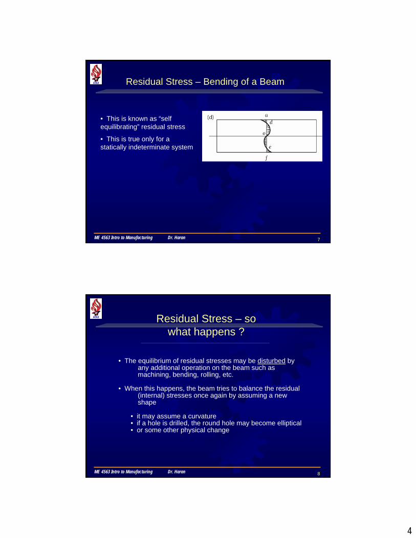
• The pattern of residual stress is as shown in (d)
• Compressive in ad and oeTensile in do and ef
• The beam is in static equilibrium with no external forces
4
7ME 4563 Intro to Manufacturing Dr. Haran
Residual Stress – Bending of a Beam
• This is known as “self equilibrating” residual stress
• This is true only for a statically indeterminate system
8ME 4563 Intro to Manufacturing Dr. Haran
Residual Stress – so what happens ?
• The equilibrium of residual stresses may be disturbed by any additional operation on the beam such as machining, bending, rolling, etc.
• When this happens, the beam tries to balance the residual (internal) stresses once again by assuming a new shape
• it may assume a curvature• if a hole is drilled, the round hole may become elliptical• or some other physical change

5
9ME 4563 Intro to Manufacturing Dr. Haran
Residual Stresses may also be caused due to:
• Temperature Gradients: such as in
• Machining operation• Welding• Casting process• Heat treatment process
• expansion and contraction due to thermal gradient is analogous to non uniform plastic deformation
• Phase Changes: in metals during or after processing – due to density differences between the phases
• Results in changes at the microscopic level which leads to residual stresses
10ME 4563 Intro to Manufacturing Dr. Haran
Residual Stress
Examples of distortion of parts with residual stresses, after machining or further processing has taken place

6
11ME 4563 Intro to Manufacturing Dr. Haran
Effects of Residual Stress
• Tensile residual stresses on surfaces – NOT desirable:
• lower fatigue life & strength – will sustain lower additional tensile stresses
• leads to stress cracking over a period of time
• Compressive residual stress on surface – Desirable – increases fatigue life
• Imparted on surfaces through shot peening or rolling
12ME 4563 Intro to Manufacturing Dr. Haran
Reduction of Residual Stress
• Further plastic deformation – apply forces to make the stress distribution uniform
• Thermal treatment - Stress-relief annealing – heating and then slow cooling
• May be diminished at room temperature by “relaxation”
• relaxation leads to warpage, hence allowances in dimensions (machining allowances) are usually made when subject to stress-relief annealing or relaxation

7
13ME 4563 Intro to Manufacturing Dr. Haran
Failure (Yield) Criteria
• The purpose of failure criteria is to predict or estimate the failure/yield of machine parts and structural members
• Materials are assumed to be homogeneous, isotropic and yield stress in tension and compression are the same. Tensile stresses are positive, compressive stresses are negative
• All criteria are presented in terms of principal stresses. Hence, all stresses are transformed to the principal stresses before applying these failure criteria
14ME 4563 Intro to Manufacturing Dr. Haran
Failure (Yield) Criteria
• These are all stress-based criteria
• Other factors/criteria may also be used in practice (vibration, stiffness, resistance to fatigue, etc.)
• Criteria are different for Ductile and Brittle materials• we will discuss only criteria for ductile materials
• Most failure criteria rely on only a handful of basic tests (such as uniaxial tensile and/or compression strength), even though most machine parts and structural members are typically subjected to multi-axial loading

8
15ME 4563 Intro to Manufacturing Dr. Haran
• In most manufacturing operations involving deformation, the stresses are usually triaxial in nature
• example: drawing, extrusion, etc.
• During the process, the material is subjected to various normal and shear stresses
• These stresses can cause yielding
• Which leads to distortion
Triaxial Stress & Yield Criteria
16ME 4563 Intro to Manufacturing Dr. Haran
• In simple uniaxial loading – we know when a material has reached a yield stress state:
• it undergoes plastic deformation
• But in a more complex state of stress such as a triaxial state of stress, relationship between stresses are required to predict when the material will yield
• These relationships are known as yield criterion
Triaxial Stress & Yield Criteria

9
17ME 4563 Intro to Manufacturing Dr. Haran
• How do we use these criteria ?
Essentially compare the loading condition to the various yield criteria. Two of the common ones:
– Tresca or Max. Shear Stress criterion
– von Mises or Distortion energy criterion
• Key concepts
– plane stress
– plane strain
Yield Criteria
18ME 4563 Intro to Manufacturing Dr. Haran
Yield in ductile materials is usually caused by the slippage of crystal planes along the maximum shear stress surface.
Therefore, a given point in the body is considered safe as long as the maximum shear stress at that point is under the yield shear stress Y obtained from a uniaxial tensile test
Triaxial Stress & Yield Criteria

10
19ME 4563 Intro to Manufacturing Dr. Haran
Yield Criteria
Tresca Yield Criterion – also known as the “maximum shear stress criterion” occurs when the maximum shear stress within an element is equal to or exceeds a critical value (a material property)
This critical value is the shear yield stress, k
τmax >= k
If the maximum Shear stress (from Mohr’s circle or equations) is equal to or exceeds k, then yielding will occur
20ME 4563 Intro to Manufacturing Dr. Haran
At the moment yield occurs, one of the principal stresses will be equal to the yield stress and the other principal stress will bezero (see the Mohr’s circle below).
This condition defines the critical value of the shear stress at which yield occurs.
According to Tresca, yield will occur only if the shear stress exceeds this value (Note that this value is half the value of the yield stress = Y/2)
Uniaxial Tensile Test
11
21ME 4563 Intro to Manufacturing Dr. Haran
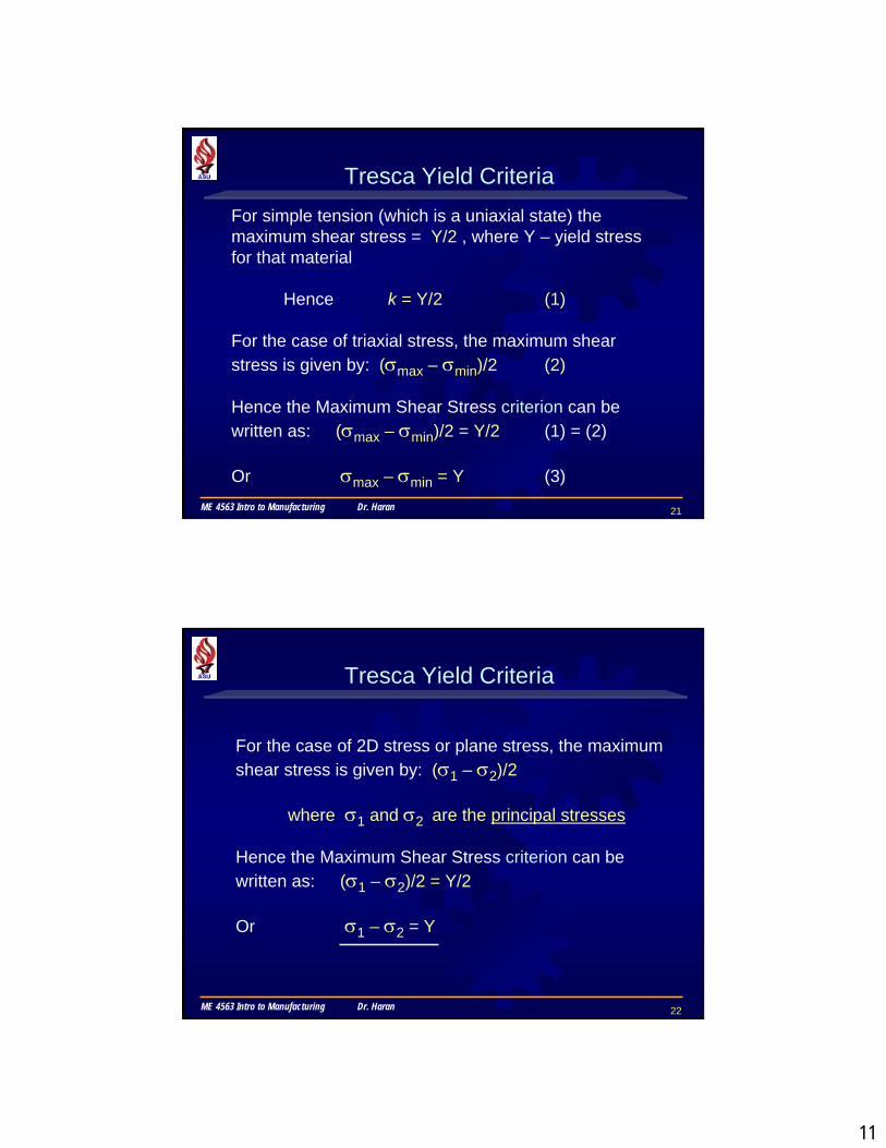
Tresca Yield CriteriaFor simple tension (which is a uniaxial state) the maximum shear stress = Y/2 , where Y – yield stress for that material
Hence k = Y/2 (1)
For the case of triaxial stress, the maximum shear stress is given by: (σmax – σmin)/2 (2)
Hence the Maximum Shear Stress criterion can be written as: (σmax – σmin)/2 = Y/2 (1) = (2)
Or σmax – σmin = Y (3)
22ME 4563 Intro to Manufacturing Dr. Haran
Tresca Yield Criteria
For the case of 2D stress or plane stress, the maximum shear stress is given by: (σ1 – σ2)/2
where σ1 and σ2 are the principal stresses
Hence the Maximum Shear Stress criterion can be written as: (σ1 – σ2)/2 = Y/2
Or σ1 – σ2 = Y

12
23ME 4563 Intro to Manufacturing Dr. Haran
or the Distortion Energy Criteria
von Mises postulated (1913) that a material will yield when the Distortional Energy at the point in question reaches a critical value.
The distortional energy written in terms of the principal stresses and the yield stress is as follows.
(σ1 – σ2)2 + (σ2 – σ3)2 + (σ3 – σ1)2 = 2Y2
Left side is stresses; right side is material property, as before
von Mises Yield Criteria
24ME 4563 Intro to Manufacturing Dr. Haran
or the Distortion Energy Criteria
• Is often used to estimate the yield of ductile materials
• In the cases of plane stress, σ3 = 0. The von Mises criterion reduces to
von Mises Yield Criteria
σ12– σ1σ2 + σ2
2 = Y2
13
25ME 4563 Intro to Manufacturing Dr. Haran
Plane Stress & Plane Strain
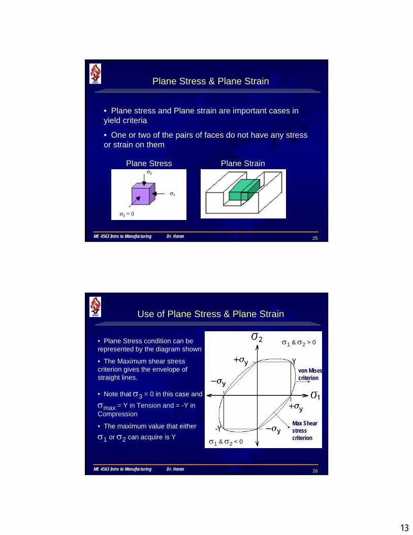
• Plane stress and Plane strain are important cases in yield criteria
• One or two of the pairs of faces do not have any stress or strain on them
Plane Stress Plane Strain
26ME 4563 Intro to Manufacturing Dr. Haran
Use of Plane Stress & Plane Strain
• Plane Stress condition can be represented by the diagram shown
• The Maximum shear stress criterion gives the envelope of straight lines.
• Note that σ3 = 0 in this case and
σmax = Y in Tension and = -Y in Compression
• The maximum value that eitherσ1 or σ2 can acquire is Y
Y
-Y
σ1 & σ2 > 0
σ1 & σ2 < 0
von Misescriterion
Max Shear stress criterion
14
27ME 4563 Intro to Manufacturing Dr. Haran
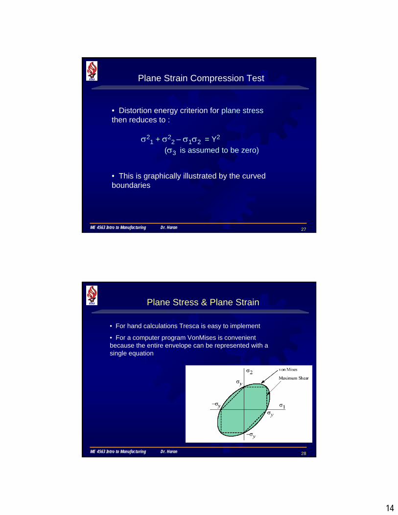
Plane Strain Compression Test
• Distortion energy criterion for plane stressthen reduces to :
• This is graphically illustrated by the curved boundaries
σ21 + σ2
2 – σ1σ2 = Y2
(σ3 is assumed to be zero)
28ME 4563 Intro to Manufacturing Dr. Haran
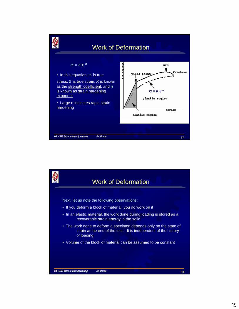
Plane Stress & Plane Strain
• For hand calculations Tresca is easy to implement
• For a computer program VonMises is convenient because the entire envelope can be represented with a single equation

15
29ME 4563 Intro to Manufacturing Dr. Haran
Plane Strain
• 3D Stress-Strain relationships are represented by these equations of generalized Hooke’s law
• When stresses are high enough to cause plastic deformation, then the stress-strain relationships are obtained from the Flow Rules (Levy-Misesequations) Eqns. 2.43
30ME 4563 Intro to Manufacturing Dr. Haran
Plane Strain
• For plastic material, Poisson’s ratio can be assumed to be = 0.5
• For plane strain condition in Fig. 2.37c & d, the generalized equation will reduce to
• For plane strain condition in Fig. 2.37c & d, ε2 = 0
• Then the stress-strain relations will reduce to

16
31ME 4563 Intro to Manufacturing Dr. Haran
Plane Strain
• For plane strain compression in Fig. 2.16 & 2.37 d, the distortion-energy criterion will then reduce to:
(use Eqn. 2.37 and substitute )
32ME 4563 Intro to Manufacturing Dr. Haran
• Volume Strain: Also known as Dilatation (∆)
• ∆ = the sum of the strains in the three directions ε1 + ε2 + ε3
• in the plastic range, volume change = 0 or ε1 + ε2 + ε3= 0
• Used to define Bulk Modulus, defined by mean stress/Dilatation
= σm /∆ = E / 3(1 – 2ν)
• σm = 1/3 (σ1 + σ2 + σ3)
Other Aspects …

17
33ME 4563 Intro to Manufacturing Dr. Haran
• Effective Stress and Effective Strain:
• Convenient means of expressing state of stress on an element (formulae given in Eqns. 2.51-54)
• Formulae based on the failure criteria for stress and strain (maximum shear stress and distortion energy criterion)
Other Aspects …
34ME 4563 Intro to Manufacturing Dr. Haran
• Comparison of Normal Stress/Strain and Shear Stress/Strain
• Several observations are made with regard to tension and torsional states of stress –
• In the Tension test, the uniaxial stress σ1 is also the
effective stress as well as the principal stress (σ2 = 0)
• In the Torsion test, principal stresses occur on planes whose normals are at 45o to the longitudinal axis; principal stresses σ1 and σ3 are equal in magnitude but opposite in
sign (σ1 = - σ3)
• The magnitude of the principal stress in torsion is the same as that of the maximum shear stress (σ1 = τ1)
Other Aspects …

18
35ME 4563 Intro to Manufacturing Dr. Haran
• Observations with regard to strains –
• In the Tension test, ε2 = ε3 = - ε1/2
• In the Torsion test, ε1 = - ε3 = γ/2
• Strain in the thickness direction is zero, i.e., ε2 = 0
• Using these observations, effective stress and strain expressions can be derived (substitute in Eqns. 2.51-54)
• It is a means to convert Tensile-test data to torsion-test data and vice versa (Eqns. 2.55-58)
Other Aspects …
36ME 4563 Intro to Manufacturing Dr. Haran
True stress - true strain curves• When the change in cross section area is taken into account incalculating stress from measured load, the true stress - true strain behavior of the material is obtained
• In many many manufacturing processes the work-piece is subjected to large strains. In this situation the strains of interest are much larger than the yield strain of the material (which is of the order of 0.002), the elastic range of deformation can be ignored and we can describe work material behavior using equation:
σ = K ε n
Work of Deformation
19
37ME 4563 Intro to Manufacturing Dr. Haran
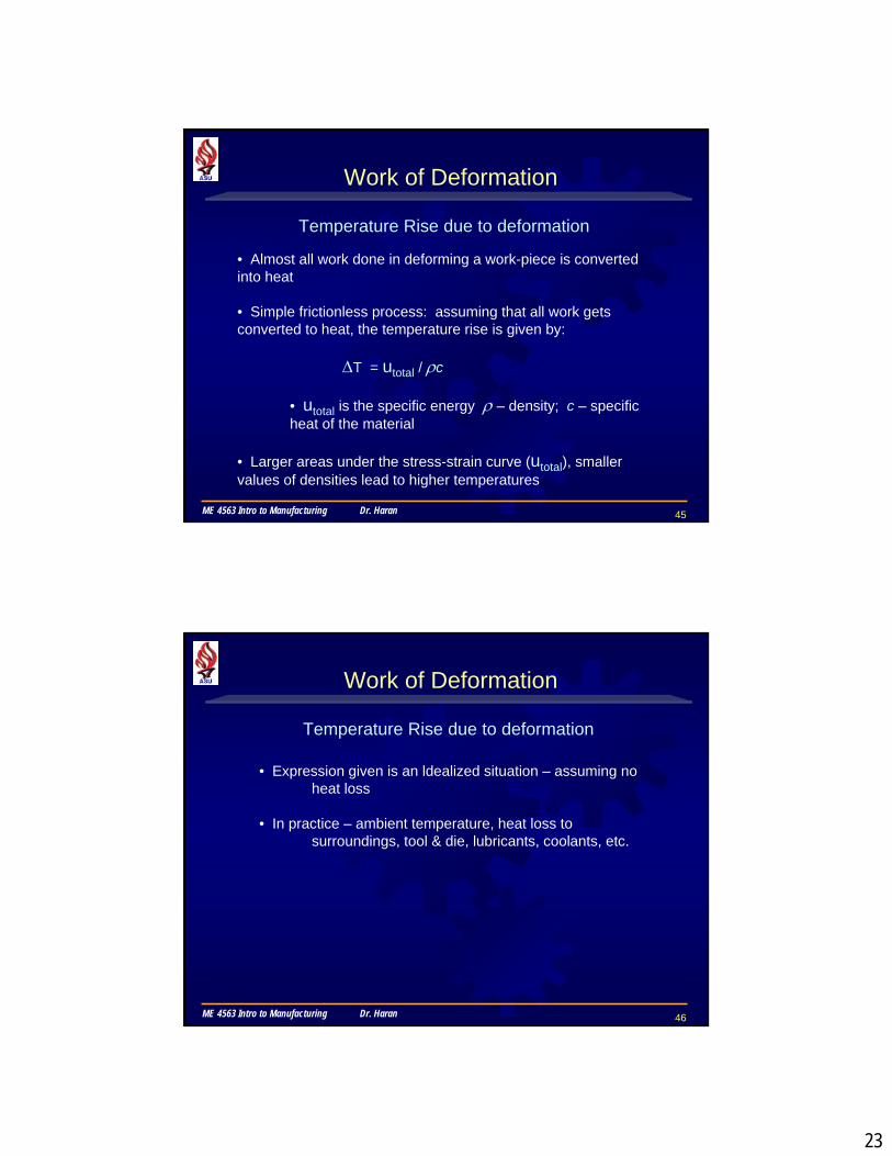
σ = K ε n
• In this equation, σ is true
stress, ε is true strain, K is known as the strength coefficient, and nis known as strain hardening exponent
• Large n indicates rapid strain hardening
Work of Deformation
σ = K ε n
38ME 4563 Intro to Manufacturing Dr. Haran
Next, let us note the following observations:
• If you deform a block of material, you do work on it
• In an elastic material, the work done during loading is stored as a recoverable strain energy in the solid
• The work done to deform a specimen depends only on the state of strain at the end of the test. It is independent of the history of loading
• Volume of the block of material can be assumed to be constant
Work of Deformation

20
39ME 4563 Intro to Manufacturing Dr. Haran
Based on these observations, we define the Specific Energy of a solid as the work done per unit volume to deform a material from a stress free reference state to a loaded state
Work = Specific Energy x Volume
Work of Deformation
To calculate specific energy for any given strain, we integrate the area underneath the true stress-true strain diagram up to the given true-strain value
40ME 4563 Intro to Manufacturing Dr. Haran
To determine the efficiency of a Manufacturing Process (such as forging, forming, etc.) it will be necessary to know how much energy has been consumed by the process
Efficiency can be written as:
η = uideal / utotal , where
utotal = uideal + ufriction + uredundant .
uideal = minimum energy required for uniform deformation
ufriction = energy required to overcome friction
uredundant = excess energy required which does not really contribute to the process
Work of Deformation

21
41ME 4563 Intro to Manufacturing Dr. Haran
So how do we determine the amount of Energy expended ?
Work of Deformation
• Work done : Force x distance• Work per unit volume : can be shown to be equal to
stress x strain = σ x ε ua
Example:V = A.L (sample of length ‘L’ and a.c.s: ‘A’)dw = F.dx for a small deformation dxWork per Unit volume: dw/V = F.dx/A.L = σ x dε Integrating both sides: w/V = u = Int(σ x dε)
42ME 4563 Intro to Manufacturing Dr. Haran
Work of Deformation
• Relation between Stress-strain depends upon the curve
-it is best to consider a True-stress-true-strain curve as it gives the actual picture of the entire deformation process
• The area under the true-stress-true-strain curve for any strain gives the energy per unit volume = Int (σ x dε)

22
43ME 4563 Intro to Manufacturing Dr. Haran
Work of Deformation
• The area under the true-stress-true-strain curve for any strain gives the energy per unit volume = Int (σ x dε)
• We use the relation: σ = K ε n in the integral to obtain the expression for ‘u’
• To obtain the work done – we multiply ‘u’ by the volume of the material deformed: W = (u) x (volume)
• u is obtained as:
44ME 4563 Intro to Manufacturing Dr. Haran
Magnitude of Efficiency varies widely, depending upon the particular process and process parameters (such as die geometry, frictional conditions, etc., in the case of extrusion).
Example Efficiencies: 30-60% for extrusion and
75-95% for rolling
Work of Deformation
23
45ME 4563 Intro to Manufacturing Dr. Haran
Work of Deformation
• Almost all work done in deforming a work-piece is converted into heat
• Simple frictionless process: assuming that all work gets converted to heat, the temperature rise is given by:
∆T = utotal / ρc
• utotal is the specific energy ρ – density; c – specific heat of the material
• Larger areas under the stress-strain curve (utotal), smaller values of densities lead to higher temperatures
Temperature Rise due to deformation
46ME 4563 Intro to Manufacturing Dr. Haran
Work of Deformation
• Expression given is an ldealized situation – assuming no heat loss
• In practice – ambient temperature, heat loss to surroundings, tool & die, lubricants, coolants, etc.
Temperature Rise due to deformation

24
47ME 4563 Intro to Manufacturing Dr. Haran
A Recap …
• Manufacturing process involve changes in shape by plastic deformation – Mechanical Properties are important factors (2.1):
• Strength, Elasticity, Ductility, Hardness, Fatigue, Energy required for plastic deformation, etc.
• Tension test – Allows for modeling of processes such as Drawing, Sheet-metal forming, etc. (2.2)
• Measure properties such as Modulus of Elasticity (E), Yield Stress (Y), Ultimate Strength (UTS), Poisson’s ratio (ν)
• Measure of Ductility (indirectly through elongation and reduction of area)
• True-Stress & True-Strain allows of determining Strength Coefficient (K), strain-hardening exponent (n), and toughness
48ME 4563 Intro to Manufacturing Dr. Haran
A Recap …• Compression test – Allows for modeling of processes such
as Forging, Rolling and Extrusion• Measurement of properties are subject to inaccuracy
due to presence of friction and barreling (2.3)
• Torsion test – Allows for modeling of processes such as Shearing, Cutting and various Machining processes (2.4). Conducted on tubular specimens that are subjected to twisting
• Bending and Flexure test – Allows for modeling of processes such as Sheet metal Forming, testing Tool and Die materials (2.5). Commonly used for brittle materials
• Modulus of Rupture is determined to know the stress at fracture are conducted on tubular specimens by subjecting them to “twisting forces”
25
49ME 4563 Intro to Manufacturing Dr. Haran
A Recap …
• Hardness tests – Determines resistance of a material to indentation (2.6)
• Related to strength and wear resistance, but not in itself a fundamental property. Several types of Hardness tests.
• Fatigue test – Allows for modeling of processes where the material is subjected to rapidly fluctuating loads (2.7)
• Determines endurance or Fatigue limits (maximum stress to which a material can be subjected to, without causing failure)
• Creep test – which is permanent elongation under static load over a period of time (2.8)
• Subject specimen to constant load at a given temperature; measure change in length over a given time period
• Failure is similar to that caused in a tensile test
50ME 4563 Intro to Manufacturing Dr. Haran
A Recap …
• Impact tests – Determines energy required for a specimen to break (2.9)
• Models conditions where impact loads are involved (drop forging, tools and dies) • Also useful in determining ductile-brittle transition temperature of materials
• Residual Stresses – which remain in a part after it has deformed and all loads have been removed (2.10)
• Generally undesirable• Nature and extent of the stresses depend upon the manner
it has been deformed (tension/compression/shear)• May be reduced by stress-relief annealing, further plastic
deformation or by relaxation

26
51ME 4563 Intro to Manufacturing Dr. Haran
A Recap …
• Metal working operations involve subjecting the work-piece to 3-D stresses through dies and other tools (2.11)
• Yield criteria establishes relationships between the maximum uniaxial yield stress of the material and the applied stresses• Maximum Shear stress (Tresca) and Distortion energy (von Mises) criteria most commonly used
• Energy is required to deform materials – Work of Deformation per unit volume of material becomes an important factor (2.12)
• Comprised of ideal, frictional, and redundant work components• Gives information on force and energy requirements• Also indicates amount of heat developed and hence, temperature rise in the workpiece