mdot us-23/us-12 noise report - michigan.gov
TRANSCRIPT

Traffic Noise Technical Draft Report US-23/US-12 Improvements Prepared for Michigan Department of Transportation 425 W. Ottawa Street, 3rd Floor P.O. Box 30050 Lansing, MI 48909 (517) 241-2445 June 2021
MDOT US-23/US-12 Draft Noise Report
Prepared for: Michigan Department of Transporation
AECOM
Prepared for: Michigan Department of Transportation 425 W. Ottawa Street, 3rd Floor P.O. Box 30050 Lansing, MI 48909 Prepared by: Paul Burge, INCE Board. Cert. Principal Acoustics and Noise Control Engineer T: 619-610-7873 E: [email protected] Yona Simonson Noise Control Specialist T: 619-6107600 E: [email protected] AECOM 401 West A Street Suite 1200 San Diego, CA 92101 aecom.com
Copyright © 2021 by AECOM
All rights reserved. No part of this copyrighted work may be reproduced, distributed, or transmitted in any form or by any means without the prior written permission of AECOM.

MDOT US-23/US-12 Draft Noise Report
Prepared for: Michigan Department of Transporation
AECOM
Table of Contents List of Acronyms and Abbreviations ............................................................................................................................... 5 Executive Summary ....................................................................................................................................................... 6 1. Introduction and Project Description ................................................................................................................... 7
1.1 Project Description................................................................................................................................... 7 1.2 Description of Alternatives ....................................................................................................................... 7
2. Traffic Noise Concepts ........................................................................................................................................ 9 2.1 Glossary of Acoustical Terms ................................................................................................................... 9 2.2 Fundamentals of Traffic Noise Assessment and Control ....................................................................... 10 2.3 Regulatory Overview ............................................................................................................................. 13 2.3.1 Federal Regulations............................................................................................................................... 13 2.3.2 State Regulations and Policies .............................................................................................................. 14
3. Methods of Noise Analysis ................................................................................................................................ 15 3.1 Defining Area or Potential Impact .......................................................................................................... 15 3.2 Field Measurement Procedures ............................................................................................................. 15 3.3 Analysis Objectives................................................................................................................................ 16 3.4 Selection of Noise-Sensitive Receptors ................................................................................................. 17 3.5 Loudest Hour Noise Conditions ............................................................................................................. 17 3.6 Noise Abatement Requirements ............................................................................................................ 17 3.7 Noise Modeling Methodology ................................................................................................................ 18 3.8 Project Traffic Data ................................................................................................................................ 18 3.9 Existing Condition and Common Noise Environments........................................................................... 19 3.9.1 Existing Land Use and Zoning ............................................................................................................... 19 3.9.2 Common Noise Environments ............................................................................................................... 19 3.9.3 Existing Noise Environment ................................................................................................................... 22 3.9.3.1 Field Noise Measurements .................................................................................................................... 22 3.9.3.2 Noise Model Validation and Results ...................................................................................................... 22
4. Noise Impact Analysis ....................................................................................................................................... 24 4.1 Future Noise Levels and Impacts .......................................................................................................... 24 4.1.1 Predicted Noise Levels and Noise Impacts ........................................................................................... 24
5. Noise Abatement Evaluation ............................................................................................................................. 25 5.1 Noise Abatement Measures ................................................................................................................... 25 5.2 Feasible and Reasonable Criteria and Requirements ........................................................................... 25 5.3 Findings and Recommendations for Noise Abatement .......................................................................... 25 5.3.1 CNE-1A Noise Abatement Analysis ....................................................................................................... 26 5.3.2 CNE-1B Noise Abatement Analysis ....................................................................................................... 27 5.3.3 CNE-2 Noise Abatement Analysis ......................................................................................................... 27 5.3.4 CNE-3 Noise Abatement Analysis ......................................................................................................... 27 5.3.5 CNE-4 Noise Abatement Analysis ......................................................................................................... 27 5.3.6 CNE-5 Noise Abatement Analysis ......................................................................................................... 27 5.3.7 CNE-6 Noise Abatement Analysis ......................................................................................................... 27 5.3.8 CNE-7 Noise Abatement Analysis ......................................................................................................... 27 5.3.9 CNE-8 Noise Abatement Analysis ......................................................................................................... 27
6. Construction Noise Analysis ............................................................................................................................. 33 6.1 Typical Construction Noise Levels ......................................................................................................... 33 6.2 Construction Noise Abatement Measures .............................................................................................. 34
7. Information for Local Government Officials ....................................................................................................... 36
MDOT US-23/US-12 Draft Noise Report
Prepared for: Michigan Department of Transporation
AECOM
8. Conclusions and Recommendations................................................................................................................. 36 9. Statement of Likelihood .................................................................................................................................... 36 10. References ....................................................................................................................................................... 36 Appendix A Noise Measurement Data and Documentation .......................................................................................... 37 Appendix B Sample TNM Input/Output Files ................................................................................................................ 53 Appendix C Predicted Noise Levels and Impacts ........................................................................................................ 55 Appendix D Noise Barrier Analysis Detail .................................................................................................................... 59
Figures
Figure 1-1 Project Overview ........................................................................................................................................... 8 Figure 2-1 Simple Noise Barrier Geometry .................................................................................................................. 13 Figure 2-2 Path Length Difference for Varying Receiver Geometry ............................................................................. 13 Figure 3-1 Long-Term Noise Measurement Data ......................................................................................................... 16 Figure 3-2. Common Noise Environments and Noise Measurement Sites .................................................................. 21 Figure 5-1 Acoustical Analysis for CNE 1A and 1B ...................................................................................................... 28 Figure 5-2 Acoustical Analysis for CNE 2 and CNE 3 .................................................................................................. 29 Figure 5-3 Wall 3A and 3B Analysis Detail ................................................................................................................... 30 Figure 5-4 Acoustical Analysis for CNE-4, CNE 5, and CNE 6 ..................................................................................... 31 Figure 5-5 Acoustical Analysis for CNE- 7, and CNE-8 ................................................................................................ 32
Tables Table 2-1 Common Indoor and Outdoor Noise Levels ................................................................................................. 11 Table 2-2 Relationship between Changes in Noise Level and Perceived Loudness .................................................... 11 Table 2-3 FHWA Noise Abatement Criteria .................................................................................................................. 14 Table 3-1 Existing and Future Peak Hour Traffic Volumes ........................................................................................... 19 Table 3-2 Common Noise Environments ...................................................................................................................... 20 Table 3-3 TNM Validation Summary ............................................................................................................................. 23 Table 4-1 Summary of Predicted Noise Levels by CNE ............................................................................................... 24 Table 5-1 Evaluated Barrier Descriptions ..................................................................................................................... 26 Table 5-2 Barrier Analysis Results................................................................................................................................ 26 Table 6-1 Typical Construction Equipment Noise Levels .............................................................................................. 34 Table 7-1 Noise Impact Distances for Undeveloped Lands ......................................................................................... 36

MDOT US-23/US-12 Draft Noise Report
Prepared for: Michigan Department of Transportation
AECOM 5
List of Acronyms and Abbreviations ANSI American National Standards Institute
CNE Common Noise Environment
CPBU Cost Per Benefited Receptor Unit
dB Decibel (measure of sound pressure level on a logarithmic scale)
dBA A-weighted decibel (sound pressure level)
DU Dwelling Unit
DUE Dwelling Unit Equivalent
FHWA Federal Highway Administration
Leq Equivalent sound level (energy averaged sound level)
Leq(1h) A-weighted, energy average sound level during a 1-hour period
LOS Level-of-Service
LT Long-Term
MDOT Michigan Department of Transportation
Mph Miles per hour
NAC Noise Abatement Criteria
NR Noise Reduction
ROW Right of Way
ST Short-Term
TNM Traffic Noise Model

MDOT US-23/US-12 Draft Noise Report
Prepared for: Michigan Department of Transportation
AECOM 6
Executive Summary This noise analysis was conducted to assess the noise impacts of the US-12/US-23 improvement project in Pittsfield Township, MI. US-12 and US-23 experience a high volume of traffic daily, this project is intended to ease congestion, increase safety, and eliminate turning conflicts. The project includes improvements to both US-12 and US-23. Improvements on US-12 include new travel lanes in both directions beginning outside the Pittsfield police station and extending across US-23 to Carpenter Road. This also includes redesigned intersections, and a new right-hand turn lane from Eastbound US-12 to Southbound Platt Road. At the interchange of US-12 and US-23, new right turns on ramps are being added in the North West and South East quadrants. Last, an auxiliary lane is being added in both directions on US-23 between I-94 and US-12, and the acceleration/de-acceleration lanes South of US-12 are also being extended. FHWA defines Type I projects as Federal highway projects in a new location, a physical alteration of an existing highway that significantly changes either horizontal or vertical alignment or increases the number of through lanes. This noise study is for a re-evaluation of the 2005 FONSI for the US-12 Improvement Study, from City of Saline to Munger Road. The noise study is required because of the addition of the NB and SB US-23 weave merge lanes north of the US-12 interchange added after the FONSI. 23 CFR 772 requires that the whole project is studied if the project is defined as a Type I. FHWA requires a noise study for all Type I projects to assess potential noise impacts and mitigation options. This noise study included on site noise measurements in the project vicinity, conducted in November of 2020. Two long term measurements were conducted, one along each highway, along with six short term measurements dispersed across the project area. A model was developed in the FHWA Traffic Noise Model (TNM) version 2.5 and validated against these field measurements. Noise sensitive receptors were then identified and classified with existing and future levels calculated in TNM 2.5. These predicted levels were checked against FHWA standards to determine impacts in the area. Mitigation for these impacts were analyzed according to MDOT feasibility and reasonableness standards. The project includes eight Common Noise Environments (CNEs), with impacts identified in six of the eight. Abatement was considered in several locations but only recommended in two. A summary of these findings is presented in table ES-1 and discussed in more detail in the body of the report.
Table ES-1 Summary of Project Impacts and Proposed Noise Abatement
CNE Description/Location 2020 Impact 2040 Impacts Recommended Noise Abatement
CNE-1A Single Family Homes, South of US-12, West of Platt
5 7 650-foot Noise Wall
CNE-1B Commercial, Vacant, Agricultural North of US-12, West of Platt
0 0 No Impacts
CNE-2 Single and Multi-family Homes South of US-12 Between Platt and US-23
6 7 Not Recommended
CNE-3 Single and Multi-family Homes North of US-12 Between Platt and US-23
12 12 486-foot Noise Wall
CNE-4 Single Family Homes, South of US-12, East of Carpenter Rd
0 0 No Impacts
CNE-5 Commercial and Industrial Land Use, East of US-23, North of US-12
0 0 No Impacts
CNE-6 Single Family Home, West of US-23, North of US-12
1 1 Not Recommended
CNE-7 Single Family Homes, West of US-23, South of US-12
3 3 Not Recommended
CNE-8 Single Family Homes, East of US-23, South of US-12
2 2 Not Recommended

MDOT US-23/US-12 Draft Noise Report
Prepared for: Michigan Department of Transportation
AECOM 7
1. Introduction and Project Description
1.1 Project Description This project includes improvements to both US-12 and US-23. Improvements on US-12 include new travel lanes in both directions beginning outside the Pittsfield police station and extending across US-23 to Carpenter Road. This also includes redesigned intersections, and a new right-hand turn lane from Eastbound US-12 to Southbound Platt Road. At the interchange of US-12 and US-23, new right turns on ramps are being added in the North West and South East quadrants. Last, an auxiliary lane is being added in both directions on US-23 between I-94 and US-12, and the acceleration/deacceleration lanes South of US-12 are also being extended. The general project location, project limits and areas of project improvements are shown in Figure 1-1.
This noise study is for a re-evaluation of the 2005 FONSI for the US-12 Improvement Study, from City of Saline to Munger Road. The noise study is required because of the addition of the NB and SB US-23 weave merge lanes north of the US-12 interchange added after the FONSI. 23 CFR 772 requires that the whole project is studied if the project is defined as a Type I. FHWA requires a noise study for all Type I projects to assess potential noise impacts and mitigation options. FHWA defines a Type I project as a Federal highway project being constructed in a new location, a significant change in horizontal or vertical alignment of an existing roadway, or an increase in the number of through-traffic lanes. As this project includes that addition of new travel lanes along both US-12 and US-23, the project as defined in the environmental document meets the Type 1 project criteria and requires a noise analysis.
1.2 Description of Alternatives This project includes one future build alternative to be evaluated:
• Future build (includes all proposed improvements and projected traffic volumes for year 2045)

MDOT US-23/US-12 Draft Noise Report
Prepared for: Michigan Department of Transportation
AECOM 8
Figure 1-1 Project Overview

MDOT US-23/US-12 Draft Noise Report
Prepared for: Michigan Department of Transportation
AECOM 9
2. Traffic Noise Concepts The following glossary of acoustical terms is intended to help frame discussion of project-generated noises and their potential effects on neighboring communities in the project area.
2.1 Glossary of Acoustical Terms Noise: Whether something is perceived as a noise event is influenced by the type of sound, the perceived importance of the sound, and its appropriateness in the setting, the time of day, and the type of activity during which the noise occurs, and the sensitivity of the listener. Local jurisdictions may have legal definitions of what constitutes “noise” and such environmental parameters to consider.
Sound: For this analysis, sound is a physical phenomenon generated by vibrations that result in waves that travel through a medium, such as air, and result in auditory perception by the human brain.
Frequency: Sound frequency or “pitch” is measured in hertz (Hz), which is a measure of how many times each second the crest of a sound pressure wave passes a fixed point. For example, when a drummer beats a drum, the skin of the drum vibrates a number of times per second. When the drum skin vibrates 100 times per second, it generates a sound pressure wave that is oscillating at 100 Hz, and this pressure oscillation is perceived by the brain as a tonal pitch of 100 Hz. Sound frequencies between 20 and 20,000 Hz are within the range of sensitivity of the best human ear.
Amplitude or Level: Sound levels are measured in decibels (dB) using a logarithmic scale. A sound level of zero dB is approximately the threshold of human hearing and is barely audible under extremely quiet listening conditions. Normal speech has a sound level of approximately 60 dB. Sound levels above approximately 110 dB begin to be felt inside the human ear as discomfort and eventually as pain at 120 dB and higher levels. The minimum change in the sound level of individual events that the average human ear can detect is about 1 to 2 dB. A 3 to 5 dB change is readily perceived. A change in sound level of about 10 dB usually is perceived by the average person as a doubling (or if decreasing by 10 dB, halving) of the sound’s loudness. Table 2-1 shows typical indoor and outdoor sounds and their corresponding dB levels, arranged on what often is referenced as an “acoustic thermometer” to show relative loudness.
Sound pressure: Sound level usually is expressed by reference to a known standard. This report refers to sound pressure level, which is expressed on a logarithmic scale with respect to a reference value of 20 micropascals. Sound pressure level depends not only on the power of the source, but also on the distance from the source and the acoustical characteristics of the space surrounding the source.
A-weighting: Sound from a tuning fork contains a single frequency (a pure tone), but most sounds heard in the environment do not consist of a single frequency; instead, they are composed of a broad band of frequencies, differing in sound levels. The method commonly used to quantify environmental sounds consists of evaluating all frequencies of a sound according to a weighting system that reflects the typical frequency-dependent sensitivity of average healthy human hearing. This is called “A-weighting,” and the measured decibel level is referred to as A-weighted decibels (dBA).
Equivalent sound level: Environmental noise levels vary continuously and include a mixture of noise from near and distant sources. A single descriptor, energy-average sound level during a measured time interval (Leq), may be used to describe such sound that is changing in level from one moment to another. Leq is the energy-average sound level during a measured time interval. This is the “equivalent” constant sound level that would have to be produced by a single, steady source to equal the acoustic energy contained in the fluctuating sound level measured.
Day-night level (Ldn): The Ldn is the energy average of the A-weighted sound levels occurring during a 24-hour period, with 10 dB added to A-weighted sound levels occurring between 10 p.m. and 7 a.m. (nighttime).
Sound transmission loss (TL): The TL is a value representing 10 times the base-10 logarithm of the ratio of sound power incident on one side of a partition to the sound power transmitted through and subsequently emitting from the other side of the partition into an adjoining space (separated from the sound in the “source” space by the partition).
MDOT US-23/US-12 Draft Noise Report
Prepared for: Michigan Department of Transportation
AECOM 10
Insertion loss (IL): The IL is the reduction in noise level at a location from noise abatement means, placed in the sound path between that location and a sound source.
2.2 Fundamentals of Traffic Noise Assessment and Control Sound Propagation
Atmospheric conditions (e.g., wind, temperature gradients, humidity) can change how sound propagates over distance and can affect the level of sound received at a given location. The degree to which the ground surface absorbs acoustical energy also affects sound propagation. Sound traveling over an acoustically absorptive surface (e.g., grass) attenuates at a greater rate than sound traveling over a hard surface (e.g., pavement, expanses of open water). When located near either the sound source or the listener position, physical barriers (e.g., naturally occurring ridgelines or buildings, and other topography that block the line-of-sight between a source and receiver) also increase the attenuation of sound over distance.
Multiple Sound Sources
Because sound pressure levels in decibels are based on a logarithmic scale, they cannot be added or subtracted in an arithmetic fashion. Therefore, sound pressure level dB are logarithmically added on an energy summation basis. In other words, adding a new noise source to an existing noise source, both producing noise at the same level, does not double the noise level. Instead, if the difference between two noise sources is 10 dBA or more, the louder noise source dominates, and the resultant noise level is equal to the noise level of the louder source. In general, if the difference between two noise sources is 0 to 1 dBA, the resultant noise level is 3 dBA higher than the louder noise source, or both sources if they are equal. If the difference between two noise sources is 2 to 3 dBA, the resultant noise level is 2 dBA above the louder noise source. If the difference between two noise sources is 4 to 10 dBA, the resultant noise level is 1 dBA higher than the louder noise source.
How Noise is Measured
Sound can vary over an extremely large range of amplitudes. The decibel (dB) is a logarithmic unit that is the accepted standard unit for measuring the amplitude of sound because it accounts for these large variations in amplitude and reflects the way people perceive changes in sound amplitude. Different sounds may have different frequency content. Frequency content of a sound refers to its tonal quality or pitch. When describing sound and its effect on a human population, A-weighted (dBA) sound levels are typically used to account for the response of the human ear. The term "A weighted" refers to a filtering of the noise signal to emphasize frequencies in the middle of the audible spectrum and to de-emphasize low and high frequencies in a manner corresponding to the way the human ear perceives sound. This filtering network has been established by the American National Standards Institute (ANSI). The A-weighted noise level has been found to correlate well with peoples' judgments of the noisiness of different sounds and has been used for many years as a measure of community noise. Table 2-1 illustrates sound pressure levels in dBA of various sound sources between 0 dBA (threshold of hearing) and 120 dBA (threshold of pain). An increase of 3 dBA in noise level can barely be perceived, while an increase of 5 dBA is readily noticeable and considered a significant noise increase. A 10 dBA increase corresponds to a subjective doubling of loudness. A relationship between changes in noise level and loudness is indicated in Table 2-2. Since noise fluctuates from moment to moment, it is common practice to condense the noise level over a specified period of time into a single number called the Equivalent Noise Level (Leq). Many surveys have shown that the Leq properly predicts annoyance, and thus this metric is commonly used for noise measurements, prediction, and impact assessment.

MDOT US-23/US-12 Draft Noise Report
Prepared for: Michigan Department of Transportation
AECOM 11
Table 2-1 Common Indoor and Outdoor Noise Levels
Common Outdoor Noise Levels Noise Level
Noise Level (A-weighted decibels)
Common Indoor Noise Levels
110 Rock Band
Jet Flyover at 1000 feet 100 Inside Subway Train (NY) Gas Lawn Mower at 3 feet
Diesel Truck at 50 feet 90 Food Blender at 3 feet Noisy Urban Daytime 80 Garbage Disposal at 3 feet
Gas Lawn Mower at 100 feet 70 Vacuum Cleaner at 10 feet Commercial Area Normal Speech at 3 feet
60 Large Business Office
Quiet Urban Daytime 50 Dishwasher Next Room Quiet Urban Nighttime 40 Small Theater
Quiet Suburban Nighttime Library 30
Quiet Rural Nighttime Bedroom at Night
20 Broadcast & Recording Studio 10 0 Threshold of Hearing
Source: Adapted from Guide on Evaluation and Attenuation of Traffic Noise, AASHTO-1974
Table 2-2 Relationship between Changes in Noise Level and Perceived Loudness
Increase (or Decrease) in Noise Level Loudness Multiplied (or Divided) by 3 decibels 1.2 6 decibels 1.5
10 decibels 2 20 decibels 4
How Highway Noise is Generated
Highway noise is generated from three primary sources: tire/pavement noise, engine noise, and exhaust noise. Tire/pavement noise is the noise generated by the rubber tires rolling over the pavement surface and may vary in intensity and character depending on the type and condition of both the tires and the pavement. For automobiles and light trucks traveling at typical highway speeds (over about 50 mile/hour), tire/pavement noise is generally the dominant noise source. For medium and heavy trucks (like large commercial delivery vehicles and long-haul tractor-trailers) engine and exhaust noise also contribute to the noise that they produce. At typical highway speeds, one large truck can produce as much noise energy as ten automobiles. How highway noise is experienced at nearby homes is controlled by a number of factors, including: the total number of vehicles on the highway, the percentage of large trucks, the average speed of the vehicles, the distance to the highway, obstructions blocking the view of the highway, and meteorological conditions. Generally speaking, the more vehicles, the higher percentage of large trucks or the closer one is to the highway, the greater the noise will be. Intervening obstructions, either manmade (buildings, walls, berms) or natural (such as intervening terrain) will reduce noise levels. Foliage and vegetation can reduce noise levels, but it must be dense (completely obscuring the view of the highway) and thick (on the order of 50 to 100 feet) in order to make a noticeable difference.
How Highway Noise Can Be Reduced
Highway noise can be reduced in several ways. Here are some of the most recognized:
MDOT US-23/US-12 Draft Noise Report
Prepared for: Michigan Department of Transportation
AECOM 12
Traffic Controls The faster vehicles travel, and the higher percentage of large trucks, the louder the noise. Reduced speed limits, or more rigorously enforced existing speed limits, and heavy truck restrictions will reduce noise levels. However, the implementation of such measures is often politically difficult for the sake of lower noise levels alone.
Land Use Controls: Perhaps the most common sense and fiscally responsible solution to highway noise, and one favored by most highway agencies is to restrict the development of lands near highways. Restricting development of land near new highway corridors to non-noise sensitive land uses, such as commercial or industrial activities can eliminate most noise problems. However, this approach is not suitable for circumstances when land near existing or future highways has already been developed for residential land use. Quieter Vehicle Noise Sources Quieter vehicles mean less highway noise. For automobiles this means quieter tires (since tire/pavement noise is the dominant noise source). For large trucks, the EPA has established standards for maximum noise levels for new and in-use trucks. The maximum noise levels for new trucks are lower than those for some older trucks, so as old trucks are phased out and replaced with newer ones the noise produced by the average truck may go down.
Noise Barrier Walls and Berms Noise barriers, both structural walls and earthen berms, are often constructed specifically for the purpose of reducing highway noise levels. Noise barriers can be very effective for reducing noise levels at nearby homes, often reducing noise levels by as much as 10 decibels at the closest homes (a perceived halving of loudness). Noise barriers can be expensive to build, on the order of $2 million per mile. Because of their cost, the construction of noise barriers is often restricted to large highway improvement or construction projects. Some jurisdictions; however, are quite active in constructing “retrofit” noise barrier on existing highways.
Quieter Pavements It has long been recognized that some pavement types tend to be quieter than others. White concrete pavement, for example, is typically louder than asphalt blacktop. White concrete with tining (grooves cut into the pavement surface) is louder still. However, white concrete pavement (also known as Portland Concrete Cement, or PCC) is thought to be more durable, and perhaps safer than blacktop pavements (due to better skid resistance and drainage). There is also considerable concern that the low noise advantages of some blacktop pavements may diminish over time. As the tiny “nooks and crannies” in the blacktop pavement that give it acoustical absorption may fill up with silt and sand or become compressed over time, the acoustical benefits are reduced. The quest for quiet, safe and durable highway pavements is currently the focus of a considerable amount of research.
How Noise Barriers Work Noise barriers reduce noise levels by interrupting or lengthening the path that the noise takes between the source and the receiver. In order to be effective at reducing noise, noise barriers must be able to block the “line of sight” between the object producing the noise (like vehicles on the highway) and the person subjected to the noise (like residents living near the highway). The amount that the noise will be reduced is related to the path length difference between the “direct path” that the uninterrupted sound would take between the source and receiver (with no barrier) and the “diffracted path” that the sound must take going over or around the barrier, as illustrated in Figure 2-1

MDOT US-23/US-12 Draft Noise Report
Prepared for: Michigan Department of Transportation
AECOM 13
Figure 2-1 Simple Noise Barrier Geometry
Noise barriers may work better for some homes than for others. In Figure 2-2, below, home “A” is relatively close to the highway where the noise barrier can provide a large path length difference between the direct and diffracted paths, resulting in a substantial noise reduction (perhaps as much as 10 to 15 decibels). Home “B” is further from the barrier and the path length difference is not as great, resulting in less noise reduction (perhaps 7 to 10 decibels). Home “C” is even further from the highway, and also elevated above the highway level, providing an even smaller path length difference (resulting in a noise reduction of perhaps 3 to 5 decibels). In general, for a given barrier height and location, the further the receiver is from the barrier or the higher the receiver is elevated, the smaller the path length difference (or angle of diffraction) and the smaller the resulting noise reduction.
Figure 2-2 Path Length Difference for Varying Receiver Geometry
2.3 Regulatory Overview
2.3.1 Federal Regulations
The FHWA noise policy is contained within The Code of Federal Regulations, Title 23, Part 772 (23 CFR 772) which provides procedures for preparing operational and construction noise studies and evaluating noise abatement considered for federal and federal-aid highway projects. The code was recently updated in July of 2010. Under the current version of 23 CFR 772.5, projects are categorized as Type I, Type II or Type III projects. The FHWA defines a Type I project as a proposed federal or federal-aid highway project for the construction of a highway on a new location, or the physical alteration of an existing highway which significantly changes either the horizontal or vertical alignment, or increases the number of through-traffic lanes. The proposed project is a Type I project as defined by the FHWA.
Type I projects include those that create a completely new noise source, as well as those that increase the volume or speed of traffic or move the traffic closer to a receptor. Type I projects include the addition of an interchange, ramp, auxiliary lane, or truck-climbing lane to an existing highway, or the widening of an existing ramp by a full lane width for its entire length. Projects unrelated to increased noise levels, such as lighting, signing, and landscaping, are not normally considered Type I projects.

MDOT US-23/US-12 Draft Noise Report
Prepared for: Michigan Department of Transportation
AECOM 14
Under 23 CFR 772.13, noise abatement must be considered for Type I projects if the project is predicted to result in a traffic noise impact. In such cases, 23 CFR 772 requires that the project sponsor “consider” noise abatement before adoption of the final NEPA document. This process involves identification of noise abatement measures that are reasonable, feasible, and likely to be incorporated into the project, and of noise impacts for which no apparent solution is available.
Traffic noise impacts, as defined in 23 CFR 772.5, occur when the design year condition noise levels approach or exceed the noise abatement criteria (NAC) specified in 23 CFR 772, or design year condition noise levels create a substantial noise increase over existing noise levels. 23 CFR 772 does not specifically define the terms “substantial increase” or “approach”; these criteria are defined in the MDOT Noise Analysis and Abatement Handbook (July 13, 2011), as described in the following section.
Table 2-3 summarizes the FHWA NAC corresponding to various defined land use activity categories. Activity categories and related traffic noise impacts are determined based on the actual land use in a given area.
In identifying noise impacts, primary consideration is given to exterior areas of frequent human use. Interior noise impacts will only be addressed for land uses listed with Activity Category D.
Table 2-3 FHWA Noise Abatement Criteria
Activity Category
Activity Criteria
Evaluation Location
Activity description
Leq(h) L10(h) A 57 60 Exterior Lands on which serenity and quiet are of extraordinary significance and serve
an important public need and where the preservation of those qualities is essential if the area is to continue to serve its intended purpose.
B 67 70 Exterior Residential C 67 70 Exterior Active sport areas, amphitheaters, auditoriums, campgrounds, cemeteries, day
care centers, hospitals, libraries, medical facilities, parks, picnic areas, places of worship, playgrounds public meeting rooms, public or nonprofit institutional structures, radio studios, recording studios, recreation areas, Section 4(f) sites, schools, television studios, trails, and trail crossings.
D 52 55 Interior Auditoriums, day care centers, hospitals, libraries, medical facilities, places of worship, public meeting rooms, public or nonprofit institutional structures, radio stations recording studios, schools, and television studios.
E 72 75 Exterior Hotels, motels, offices, restaurants/bars, and other developed lands, properties or activities not included in A-D or F.
F -- -- -- Agriculture, airports, bus yards, emergency services, industrial, logging, maintenance facilities, manufacturing, mining, rail yards, retail facilities, shipyards, utilities (water resources, water treatment, electrical), and warehousing.
G -- -- -- Undeveloped lands that are not permitted.
1 Either Leq(h) or L10(h) (but not both) may be used on a project. 2 The Leq(h) and L10(h) Activity Criteria values are for impact determination only, and are not design standards for noise 3 Includes undeveloped lands permitted for this activity
2.3.2 State Regulations and Policies
MDOT has published the noise policy which provides guidelines in the analysis of highway traffic noise and the evaluation of noise mitigation measures. Effective July 13, 2011, the MDOT Highway Noise Analysis and Abatement Handbook (hereafter referred to as “the MDOT handbook”) also includes current policies, procedures, and practices to be used by agencies that sponsor new construction or reconstruction of federal or federal-aid highway projects. The MDOT noise handbook defines that a noise impact occurs when the sound level approaches or exceeds the assigned NAC level for a specific category, which is defined as an Leq(h) sound level 1 dBA less than the NAC identified in 23 CFR 772. This means that for an Activity Category B land use (residential), a peak hour noise level of 66 dBA is considered to approach the NAC of 67 dBA and is identified as an impact. The MDOT noise handbook defines a noise increase as substantial when the predicted traffic noise levels with project implementation exceed existing noise levels by 10 dBA. The MDOT noise handbook provides detailed technical
MDOT US-23/US-12 Draft Noise Report
Prepared for: Michigan Department of Transportation
AECOM 15
guidance for the evaluation of highway traffic noise. This includes field measurement methods, noise modeling methods, and report preparation guidelines. In addition to the NAC criteria above, the MDOT noise handbook also specifies the following definitions and policies:
Benefited Receptor is the recipient of an abatement measure that receives a noise reduction at or above the minimum threshold of 5 dBA.
Feasible Noise Abatement Measure is a mitigation measure that is acoustically feasible and meets engineering requirements for constructability. A noise abatement measure is considered feasible when it can provide at least a 5 dBA reduction to at least 75% of impacted noise receptors, and meets constructability, safety, access, utility, and drainage requirements.
Reasonable Noise Abatement Measure is an abatement measure that has been determined to be cost effective if it costs at or below the allowable cost per benefited receptor unit (CPBU) of $49,301.00 , and is considered acceptable to the majority of residents and property owners who benefit from the noise abatement. The MDOT design year attenuation requirement requires that a minimum of one benefited receptor achieve a 10 dBA noise reduction, and that 50% of benefited receptors must achieve a 7dBA reduction.
3. Methods of Noise Analysis
3.1 Defining Area or Potential Impact The extent of the noise study analysis area should include all receptors potentially impacted by the project. The FHWA does not establish a fixed distance to define the noise impact analysis area. Historically, absolute noise impacts (those areas with noise levels approaching or exceeding the NAC – 66 dBA for residential land uses) rarely exist beyond about 500 feet from the roadway. The MDOT noise handbook defines the study zone to be a minimum of 500 feet, including all noise-sensitive receptors on all sides of the highway. If an impact is identified at 500 feet, the next closest receptor would need to be analyzed until a distance where impacts are no longer identified is reached. If no receptors are located within the 500-foot zone, then the closest receptor(s) should be analyzed.
3.2 Field Measurement Procedures A number of field noise measurements were conducted for this project. In general, the noise measurement procedures in the field follow recommended standard procedures, including those outlined in the FHWA’s Measurement of Highway Related Noise, May 1996, and the MDOT noise handbook. Specifically, the following practices and procedures were used.
The short-term noise measurements (typically 15-25 minutes) were conducted at actual or representative receptor locations and were used primarily to validate noise models (at locations where traffic noise was dominant).
Short-term noise measurements were generally conducted at exterior areas of frequent human use and were only conducted during periods of free-flowing traffic, dry roadways, and low to moderate wind speeds (less than 12 mph to avoid extraneous wind noise).
Two long-term measurements (consecutive 24-hour periods) were also deployed outside the Pittsfield Police Dept along US-12 and at 3858 Bestech Dr along US-23 in order to help determine the loudest noise hour. Based upon the collected data, the loudest noise hour was from 7:00 AM to 8:00 AM for both US-12 and US 23. A graph of the long-term measurement data (LT-1 and LT-2) is shown in Figure 3-1.

MDOT US-23/US-12 Draft Noise Report
Prepared for: Michigan Department of Transportation
AECOM 16
Figure 3-1 Long-Term Noise Measurement Data
Only ANSI (American National Standards Institute) Class I sound level meters were used for both short-term and long-term measurements. The meters were subjected to a field calibration check before and after each measurement period. Calibration certificates for each meter used in the Project can be found in Appendix A.
Concurrent traffic counts (classified in auto, medium and heavy trucks, buses, and motorcycles) for the acoustically dominant road were conducted for each short-term measurement. Traffic was videotaped during the measurements and counted. The traffic counts can be found in Table 3-3.
All field data was recorded on field data sheets, which included the time, name and location of the measurement, instrumentation data, observed meteorological data, field calibration data, a measurement site diagram, GPS coordinates, and notes as to the dominant noise sources and any other observed acoustically relevant events (such as aircraft over-flights, emergency vehicle pass bys, etc.). Field sheets and photographs of measurement sites developed in this project can be found in Appendix A.
3.3 Analysis Objectives The purpose of this noise analysis report is to identify, and document potential noise impacts associated with the proposed future Project and to identify feasible and reasonable abatement. The general analysis procedure for the Project noise study includes the following steps:
1. Review Project Description: Review the project description and project data to be analyzed and collect additional required data (including roadway design files, existing and future traffic data, land use data, etc.). Consider all alternatives, design options, and construction phasing scenarios. This information is presented in Section 1 of this report.
2. Identify Regulatory Framework: Investigate and establish the regulatory framework to be followed for the noise analysis, including federal, state and local regulations and ordinances applicable to the Project. This information is presented in Section 2 of this report.
3. Noise Analysis Methodology and Establish Existing Land Use and Noise Environment: Investigate and document the existing noise environment for the Project area, including existing noise sensitive land uses and existing noise levels in the Project area. These were accomplished with a careful review of local zoning information, review of aerial photography and a site visit to the Project area. This information is presented in Section 3 of this report.
MDOT US-23/US-12 Draft Noise Report
Prepared for: Michigan Department of Transportation
AECOM 17
4. Predict Future Noise Levels and Assess Noise Impacts: Future noise levels at noise sensitive land uses for the future build alternative are predicted using the FHWA Traffic Noise Model (TNM) Version 2.5. For each alternative, compare future noise levels (as well as increases in future noise levels over existing noise levels) to appropriate identified noise impact criteria and quantify resulting noise impacts. This information is presented in Section 4 of this report.
5. Evaluate Noise Abatement: Where noise impacts are identified, evaluate potential noise abatement measures. Abatement measures are evaluated for feasibility and reasonableness according to FHWA and MDOT standards. This information is presented in Section 5 of this report.
6. Construction Noise Considerations: Analyze potential construction noise impacts and discuss available mitigation options. This information is presented in Section 6 of this report.
7. Information for Public Officials: Provide or identify appropriate information for local public officials to help avoid future noise impacts. This information is presented in Section 7 of this report.
A more detailed accounting of the specific procedures involved in each of the above analysis steps is provided in the indicated report section.
3.4 Selection of Noise-Sensitive Receptors In general, noise-sensitive receptors are selected to represent potentially impacted land uses within the Project area. A common noise environment, or CNE, is generally defined as a group of receptors within the same Activity Category in Table 2-3 that are exposed to similar noise sources and levels; traffic volumes, traffic mix, and speed; and topographic features. Generally, common noise environments occur between two secondary noise sources, such as interchanges, intersections, cross-roads. The delineated CNEs for this Project are described in Section 3 of this report. Within each CNE, representative noise measurements and noise prediction locations are identified. Typically, each CNE would have one short-term measurement location and multiple noise prediction locations. The number and locations of the receptors (measurement and modeling locations) within each CNE are selected to adequately represent all of the noise-sensitive property units (dwellings) within that CNE, and these properties may include Activity Categories A through E and G in Table 2-3 (including residential, noise sensitive commercial, parks, schools, hotels, and undeveloped lands.). Activity Category F (agriculture, retail, industrial, transportation, and utilities), may still be located within a CNE, but would be considered a noise compatible land use and would not require noise analysis. For residential properties, more isolated residences would generally be modeled as individual receptors, while residences in multi-family buildings and dense neighborhoods may be modeled with one modeled receptor location representing multiple dwelling units or homes (receptors).
All noise prediction locations are placed to represent an exterior area of frequent human use. For residential properties, this would normally be an exterior activity area between the structure and the proposed project roadway, such as a pool or play area.
3.5 Loudest Hour Noise Conditions When determining noise impacts, traffic noise predictions must be made for the loudest noise hour (generally during level of service [LOS] C or D with high heavy truck volumes and speeds close to the posted speed limit or design speed). The loudest hour noise is typically either the peak vehicular truck hour or the peak vehicular volume hour (with LOS A through D conditions).
3.6 Noise Abatement Requirements According to FHWA policy and the MDOT noise handbook, once a noise impact has been identified, feasible and reasonable noise abatement measures must be considered. For noise abatement, primary consideration is given to the exterior areas of frequent human use.
When traffic noise impacts are identified, noise barrier walls, at a minimum, are required to be considered. In addition to noise walls, other abatement elements may also be considered, if appropriate and applicable, including the following:
• Traffic management measures.
MDOT US-23/US-12 Draft Noise Report
Prepared for: Michigan Department of Transportation
AECOM 18
• Alteration of horizontal and vertical alignments.
• Acquisition of property to serve as a buffer to preempt development that would be adversely impacted by traffic noise; and
• Noise insulation (NAC D Only).
When noise barriers are considered, a noise barrier design analysis must show that the barrier is feasible. This typically requires that the barrier provides a minimum required level of noise reduction. According to the MDOT noise handbook, feasible noise barriers must provide at least 5 dBA of noise reduction to at least 75% of impacted receptors. In addition to meeting minimum noise reduction requirements, noise barriers must also meet engineering and constructability feasibility requirements in terms of safety, property and emergency access, drainage control, overhead and underground utilities clearance, and other issues.
Noise barrier reasonableness is generally related to cost effectiveness and benefited receptors. The MDOT noise handbook expresses barrier cost effectiveness by a quotient formula called the Cost Per Benefited Receptor Unit (CPBU), which divides the total square-foot cost of the barrier (at a rate of $45.00/ft2) by the number of dwelling units that receive benefits. To maintain reasonableness, the total CPBU cannot exceed $49,301.00 (for FY 2021). Barriers must also achieve the MDOT noise reduction design goal of 10 dBA reduction for at least one benefited receptor, and 7dBA reduction at 50% of benefitted receptors.
If noise barriers are determined to be reasonable and feasible as defined above, then the viewpoints of property owners and residences should be taken into consideration. Approval by a simple majority (greater than 50%) of all responding benefited owners and residences is needed to implement noise abatement. Public votes should occur during final design and could happen during the Context Sensitive Design aesthetic public input phase..
3.7 Noise Modeling Methodology Future build noise levels, along with existing noise levels, were predicted using the FHWA TNM Version 2.5, the most recent version available at the time of the analysis. All conventional modeling techniques and recommendations for TNM by both FHWA and MDOT were implemented. These included the following modeling procedures and conventions:
• TNM roadways were generally modeled as bundled roadways with no more than three lanes per roadway.
• All roadway pavement types were modeled as “Average”.
• Traffic speeds and volumes for peak traffic hour as provided in the traffic data were modeled to predict worst case noise levels. Traffic speeds and volumes used in this analysis were based on the predicted traffic data included in Table 3-1.
• Existing terrain lines (topography) and buildings were modeled where appropriate.
• All TNM model runs were detail checked for accuracy by an independent noise analyst.
• All TNM model runs are available upon request
3.8 Project Traffic Data Predicted traffic data for the existing and Future Build were provided by the Michigan Department of Transportation. A summary of the traffic data used for this analysis can be found in Table 3-1

MDOT US-23/US-12 Draft Noise Report
Prepared for: Michigan Department of Transportation
AECOM 19
Table 3-1 Existing and Future Peak Hour Traffic Volumes
Existing Traffic (vehicles per hour) Future Traffic (vehicles per hour)
2020 AM Peak 2045 AM Peak
US-23 US-12 US-23 US-12
NB SB EB WB NB SB EB WB
Speed (mpg)1 70/65/65 70/65/65 45/45/45 45/45/45 70/65/65 70/65/65 45/45/45 45/45/45
Total 3025 1795 1383 1149 3565 2115 1501 1354
Auto and Light Trucks 2719 1613 1298 1078 3056 1901 1408 1271
Medium Duty Trucks 25 15 14 11 28 18 15 14
Heavy Duty Tucks 281 167 71 59 316 197 77 70
Notes 1. posted speeds or for Autos/Medium Trucks/ Heavy Trucks Source: MDOT Traffic Memo
3.9 Existing Condition and Common Noise Environments
3.9.1 Existing Land Use and Zoning
Land uses within the Project study area are a mix of residential (single and multi-family), commercial, industrial and undeveloped land. Undeveloped areas are primarily for future residential development, with some areas reserved for future commercial development as well.
3.9.2 Common Noise Environments
To better categorize the potential noise impacts and evaluate noise abatement for the various project alternatives, all of the potentially impacted, noise-sensitive receptors have been organized into Common Noise Environments (CNEs). A CNE is defined as an area containing land uses which share a common highway traffic noise influence. Descriptions of delineated CNEs, including location, primary land use and type of noise-sensitive receptors are listed in Table 3-2. Figure 3-2 shows an overview of the Project area illustrating all the defined CNEs.

MDOT US-23/US-12 Draft Noise Report
Prepared for: Michigan Department of Transportation
AECOM 20
Table 3-2 Common Noise Environments
CNE Description Land Use Measurement ID
CNE-1A Area south of US-12, west of Platt Rd. Single Family Residential, municipal, park
ST-1, LT-1
CNE-1B* Area north of US-12, west of Platt Rd. Commercial, undeveloped, agricultural
None
CNE-2 Area south of US-12, Platt to US-23 Single and Multi-family Residential, Undeveloped
ST-2
CNE-3 Area north of US-12, Platt to US-23 Single and Multi-family Residential, Undeveloped
ST-3
CNE-4 Area south of US-12, east of US-23 Single Family Residential ST-4
CNE-5 Area East of US-23, north of US-12 Commercial, undeveloped ST-5, LT-2
CNE-6 Area East of US-23, north of US-12 Single Family Residential, undeveloped
ST-6
CNE-7* Area West of US-23, South of US-12 Single Family Residential, undeveloped
None
CNE-8* Area East of US-23, South of US-12 Single Family Residential, undeveloped
None
*Note: CNE-1B, CNE-7 and CNE-8 were identified and added to the project area after the noise measurement survey was completed, so no noise
measurements are available for those areas.

MDOT US-23/US-12 Draft Noise Report
Prepared for: Michigan Department of Transportation
AECOM 21
Figure 3-2. Common Noise Environments and Noise Measurement Sites
MDOT US-23/US-12 Draft Noise Report
Prepared for: Michigan Department of Transportation
AECOM 22
3.9.3 Existing Noise Environment
3.9.3.1 Field Noise Measurements Multiple noise measurements were conducted for this project on November 16th and 17th, 2020. Noise measurements were conducted to provide information for noise model validation (short-term measurements with accompanying classified traffic counts) and to establish the loudest traffic noise hour. Noise measurements were conducted as described in Section 2.3. Appendix A includes measurement-related materials.
A total of six short-term (ST) noise measurements were conducted as summarized in Table 3-3. Figure 3-2 contains an aerial figure of the Project area showing each measurement location.
3.9.3.2 Noise Model Validation and Results The FHWA TNM Version 2.5 (TNM) was used to predict noise levels for the future build alternative as well as existing noise levels at receptor locations where noise levels are dominated by traffic noise on project roadways. To demonstrate that the noise model is predicting noise levels within a reasonable margin of error, the noise model runs are validated by comparing predicted noise levels to measured noise levels for similar traffic conditions. However, since the TNM only predicts noise levels associated with traffic noise, the model runs can only be validated at measurement locations where current noise levels are dominated by project roadways. For this project, noise model validation was possible for all six short- term noise measurement locations. Noise models are considered to be validated if the difference between measured and modeled noise levels for comparable conditions is 3 dBA or less. The successful results of the noise validation effort are presented in Table 3-3.

MDOT US-23/US-12 Draft Noise Report
Prepared for: Michigan Department of Transportation
AECOM 23
Table 3-3 TNM Validation Summary
Measurement ID and Location Traffic Measured Leq, dBA
Modeled Leq, dBA
Difference
ST-1, 6227 W Michigan Ave
Type US-12 EB US-12 WB
73.8 71.4 -2.4 Auto 696 736
Medium Trucks 0 20 Heavy Trucks 48 28
ST-2, 3350 Textile Road
Type US-12 EB US-12 WB
64.4 65.3 0.9 Auto 868 820
Medium Trucks 36 16 Heavy Trucks 52 32
ST-3, 5807 Hampshire Ln
Type US-12 EB US-12 WB
63.2 63.5 0.3 Auto 740 792
Medium Trucks 16 36 Heavy Trucks 32 36
ST-4, 5495 W Michigan Ave
Type US-12 EB US-12 WB
63.5 64.4 0.9 Auto 721 788
Medium Trucks 20 24 Heavy Trucks 36 40
ST-5, 3858 Bestech Dr.
Type US-23 NB US-23 SB
75.0 75.6 0.6 Auto 1124 1204
Medium Trucks 36 36 Heavy Trucks 412 264
ST-6, 3667 E Morgan Rd
Type US-23 NB US-23 SB
72.2 74.6 2.4 Auto 2064 1584
Medium Trucks 48 120
Heavy Trucks 288 264
As shown in Table 3-3, all calculated differences between modeled and measured noise levels are less than 3.0 dBA, therefore the noise models for those locations are considered validated.
TNM validation runs developed for this Project are digitally archived and will be made available upon request.
MDOT US-23/US-12 Draft Noise Report
Prepared for: Michigan Department of Transportation
AECOM 24
4. Noise Impact Analysis
4.1 Future Noise Levels and Impacts This section presents predicted noise levels and noise impacts (or noise impact distances for both identified CNE areas and general undeveloped areas).
4.1.1 Predicted Noise Levels and Noise Impacts
Traffic noise impacts, as defined in 23 CFR 772.5, occur when the design year condition noise levels approach or exceed the noise abatement criteria (NAC) specified in 23 CFR 772, or design year condition noise levels create a substantial noise increase over existing noise levels. 23 CFR 772 does not specifically define the terms “substantial increase” or “approach”; these criteria are defined in the MDOT Noise Analysis and Abatement Guidelines (July 13, 2011), as described in the following section. Table 2-3 summarizes the FHWA NAC corresponding to various defined land use activity categories.
MDOT noise handbook defines that a noise impact occurs when the sound level approaches or exceeds the NAC level, which is defined as an Leq(h) sound level 1 dBA less than the NAC identified in 23 CFR 772. This means that a peak hour noise level of 66 dBA is considered to approach the NAC for Category B of 67 dBA and is identified as an impact. The MDOT noise handbook defines a noise increase as substantial when the predicted traffic noise levels with project implementation exceed existing noise levels by 10 dBA.
Future build alternative noise levels, along with existing noise levels, were predicted using the FHWA TNM Version 2.5. All conventional modeling techniques and recommendations for TNM by both FHWA and MDOT were implemented, as described in Section 3.7.
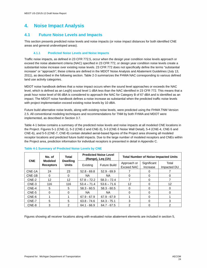
Table 4-1 below contains a summary of the predicted noise levels and noise impacts at all modeled CNE locations in the Project. Figures 5-1 (CNE-1), 5-2 (CNE-2 and CNE-3), 5-3 (CNE-3 Noise Wall Detail), 5-4 (CNE-4, CNE-5 and CNE-6), and 5-5 (CNE-7, CNE-8) contain detailed aerial-based figures of the Project area showing all modeled receptor locations and predicted future build impacts. Due to the large number of modeled receptors and CNEs within the Project area, prediction information for individual receptors is presented in detail in Appendix C.
Table 4-1 Summary of Predicted Noise Levels by CNE
CNE No. of
Modeled Receptors
Total Dwelling
Units
Predicted Noise Level (Range), Leq (1h) Total Number of Noise Impacted Units
Existing Future Build Approach or Exceed NAC
Significant Increase
Total Impacted DU
CNE-1A 24 23 52.8 - 69.8 52.9 - 69.9 7 0 7 CNE-1B 0 0 NA NA 0 0 0 CNE-2 12 12 57.8 – 72.2 58.3 – 72.4 7 0 7 CNE-3 116 116 53.4 – 71.4 53.6 – 71.6 12 0 12 CNE-4 5 5 58.3 - 60.5 58.3 - 60.5 0 0 0 CNE-5 0 0 NA NA 0 0 0 CNE-6 1 1 67.9 - 67.9 67.9 - 67.9 1 0 1 CNE-7 5 5 63.8 - 74.6 64.3 - 75.1 3 0 3 CNE-8 3 2 64.1 - 66.9 64.7 - 67.5 2 0 2
Figures showing all receiver locations along with evaluated noise abatement elements are included in section 5,

MDOT US-23/US-12 Draft Noise Report
Prepared for: Michigan Department of Transportation
AECOM 25
5. Noise Abatement Evaluation
5.1 Noise Abatement Measures According to FHWA and MDOT policies, when noise impacts are identified, noise barriers (at a minimum) must be considered as noise abatement. Other potential noise abatement measures might include heavy truck or speed restrictions, alignment changes, and depressed roadways. Of these alternatives, the Project alignment was evaluated and compared for noise impacts (as presented in section 4), but truck restrictions and speed restrictions below proposed speed limits would significantly reduce the value of the roadway. Noise barriers were evaluated for each CNE with noise impacts for feasibility and reasonableness. The following section describes the results of the barrier assessments for each evaluated CNE.
5.2 Feasible and Reasonable Criteria and Requirements In order for mitigation to be recommended, the barrier must meet certain feasibility and reasonableness requirements established by MDOT in the Noise Analysis and Abatement Guidelines.
When noise barriers are considered, a preliminary noise barrier design analysis must show that the barrier is feasible. According to the MDOT noise handbook, feasible noise barriers must provide at least 5 dBA of noise reduction to 75% of the impacted receptors. In addition to meeting minimum noise reduction requirements, noise barriers must also meet engineering and constructability feasibility requirements in terms of safety, property and emergency access, drainage control, overhead and underground utilities clearance, and other issues.
Noise barrier reasonableness is generally related to cost effectiveness and benefited receptors, where a benefited receptor receives at least 5 dBA of noise reduction (NR), and cost effectiveness is driven by a Cost per Benefited Receptor Unit (CPBU) value. The handbook identifies a CPBU of $49,301, which is a final quotient resulting from dividing the total cost of abatement (at a rate of $45.00 ft2) by the total number of benefited receptors. Additionally, The MDOT design year attenuation requirement requires that a minimum of one benefited receptor achieve a 10 dBA noise reduction, and that 50% of benefited receptors must achieve a 7dBA reduction for noise abatement to be reasonable.
To summarize, for a barrier to be considered feasible and reasonable, it must have: • A noise reduction of at least 5 dBA must be achieved at 75% of impacted receptors
• A noise reduction of 10 dBA must be achieved for at least one receptor
• A noise reduction of 7 dBA must be achieved at 50% of benefitted receptors
For a noise barrier to be considered reasonable in addition to the requirements listed above, the viewpoints of benefited property owners and residents must be taken into consideration. Greater than 50% in favor of all responding benefited owners and residents is needed to construct noise abatement. Public viewpoints and votes of benefited receptors are not part of this noise analysis but are collected during the Preliminary Engineering Phase and are recorded in the environmental documentation.
5.3 Findings and Recommendations for Noise Abatement Noise abatement was considered for each CNE with identified noise impacts. Initially, noise abatement was checked for feasibility (5 dBA reduction and at least 75% of impacted receptors and access restrictions). If abatement was determined to be feasible, the abatement was analyzed for cost effectiveness and other reasonableness factors. For all impacted receptors meeting feasibility requirements, preliminary barrier designs were evaluated using TNM. If the abatement was found to be both reasonable and feasible, it would be recommended for inclusion in the project pending a polling of viewpoints from benefited receptors. A summary of the barrier’s locations and resulting sound levels are provided in Table 5-1. The details of the barrier analysis including feasibility and reasonableness results are included in Table 5-2. The narrative results of abatement evaluations for each impacted CNE are summarized in subsequent sub-sections.
Table D-1 in Appendix D lists the existing and predicted future build noise levels as well as the noise levels with barrier per modeled receptor location. The table also includes the information regarding benefited receptors and barrier design goal achievement.

MDOT US-23/US-12 Draft Noise Report
Prepared for: Michigan Department of Transportation
AECOM 26
Table 5-1 Evaluated Barrier Descriptions
Barrier ID Location Existing
Leq (dBA)
Future Leq Range (dBA) Noise
Reduction (dBA)
Barrier Descriptions
(feet) No
Wall With Wall Length Avg
Height Wall 1A Directly South of the existing
sidewalk along US-12, between Sauk Trail and the Police Station
53-70 53-70 52-61 5-10 650 11.00
Wall 1B Directly South of the existing sidewalk along US-12, extending 380 feet Southwest of Sauk Trail
57-64 60-66 58-61 5-7 374 15.95
Wall 3A Along the ROW line North of US-12, West of Plum Hollow Dr 51-68 56-68 53-61 5-9 341 20.00
Wall 3B Directly North of US-12, along the shoulder, Extending 490 feet Northeast of Plum Hollow Dr
53-70 54-70 52-62 5-10 486 20.00
Wall 7 Along the ROW line West of US-23, extending South from the US-12 interchange
64-75 64-75 58-62 7-13 1393 20.00
Wall 8 Along the ROW line East of US-23, extending South from the US-12 Interchange
64-71 65-71 58-61 6-10 1637 16.00
Table 5-2 Barrier Analysis Results
Barrier ID
Number of Attenuated Locations
Cost Cost/Benefitted Feasible Reasonable Recommended ≥ 10 dBA
≥ 7 dBA ≥ 5 dBA (Benefitted Receptors)
# % of Benefit # % of
Impacts
Wall 1A 1 4 57% 7 100% $321,750. $45,964 Yes Yes Yes
Wall 1B 0 2 50% 4 100% $268,439 $67,110 Yes No No
Wall 3A 0 2 25% 8 100% $306,900 $38,363 Yes No No
Wall 3B 1 8 67% 12 100% $437,400 $36,450 Yes Yes Yes
Wall 7 1 4 100% 4 100% $1,253,700 $313,425 No No No
Wall 8 1 3 100% 3 100% $1,178,640 $392,880 No No No
Note: MDOT policy requires that reasonable and feasible noise walls must provide at least 10 dBA noise reduction at one impacted receptor, at least 7 dBA noise reduction for at-least 50% of benefited receptors, at least 5 dBA noise reduction for at least 50% of impacted receptors, and be constructed at an estimated cost of no more than $49,301 per benefited receptor.
5.3.1 CNE-1A Noise Abatement Analysis
CNE-1A, south of US-12, contains 24 modeled receiver locations representing a total of 23 individual single-family homes with each home representing one dwelling unit and a township office building. Seven receptors where determined to be impacted under future build conditions. One impacted receptor (R1001) was isolated from other receptors, thus abatement was not analyzed. Two noise walls were analyzed, Barrier 1A on the East side of Sauk Trail, and Wall 1B on the West side. Wall 1A was found to meet MDOT feasibility and reasonableness standards, while Wall 1B did not. Wall 1A was optimized to provide a balanced design (generally providing the best ratio of total noise reduction to cost) benefitting receptors along Sauk Trail and Harwood Cr. These walls are shown in Figure 5-1, and detailed analysis metrics can be found in Tables 5-1 and 5-2.

MDOT US-23/US-12 Draft Noise Report
Prepared for: Michigan Department of Transportation
AECOM 27
5.3.2 CNE-1B Noise Abatement Analysis
CNE-1B, north of US-12, contains two commercial buildings with no exterior use areas, an undeveloped wooded area and part of an agriculture field. None of these are no noise sensitive land uses; thus, no noise abatement was analyzed. CNE-1B is shown in Figure 5-1.
5.3.3 CNE-2 Noise Abatement Analysis
CNE-2 contains 12 modeled receptor locations representing a total of 12 individual dwelling units, 7 of which were impacted, as shown in Figure 5-2. Receptors on the East side of the CNE are isolated, with driveway access form Michigan Avenue which would preclude feasible noise barriers in this area. Thus no barriers were analyzed or recommended in CNE-2. There is also a large multifamily residential complex near the south-east corner of Michigan Avenue and Platt Road. This area was investigated for potential noise impacts and it was determined that there were no qualified exterior use areas associated with this development (no significant exterior patios, balconies, or common use areas) so noise impacts were not assessed.
5.3.4 CNE-3 Noise Abatement Analysis
CNE-3 contains 116 modeled receptor locations representing a total of 116 individual dwelling units, 12 of which were impacted. Two of the impacted receptors (3005 and 3006) are isolated single-family homes with direct driveway access to US-12, thus noise abatement was determined to be not feasible for these receptors. Several receptors were impacted near Plum Hollow Dr. Noise walls were evaluated on both sides of Plum Hollow Dr, 3A to the West and 3B to the East. Wall 3A failed to meet the design goal of achieving 7 dBA reduction at 50% of benefiting receptors as well as 10 dB reduction at one receptor, resulting in the wall being evaluated as not reasonable. Wall 3B was analyzed extending NE of Plum Hollow Dr. along the shoulder of the road. The wall was found to be feasible and reasonable. Walls 3A and 3B are shown in Figures 5-2 and 5-3 and summarized in Table 5-1 and 5-2. Please note, in Figure 5-3, overlapping receptor symbols indicate upper and lower level dwelling units, each with an exterior patio or balcony and separate receptor ID (with ID numbers 31XX for first level and 32XX for second level).
5.3.5 CNE-4 Noise Abatement Analysis
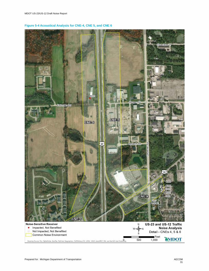
CNE-4 contained 5 modeled receptor locations representing 5 individual dwelling units, none of which were impacted. As there were no impacts, no abatement was analyzed. CNE 4 is shown in Figure 5-4.
5.3.6 CNE-5 Noise Abatement Analysis
CNE-5 contains no noise sensitive land uses; thus no abatement was analyzed. CNE 5 is shown in Figure 5-4
5.3.7 CNE-6 Noise Abatement Analysis
CNE-6 contained one modeled receptor location representing one dwelling unit, as shown in Figure 5-4, which was impacted. As an isolated receptor, and following a basic assumption that a barrier would need to extend at least 3 times the distance from the barrier to the receiver in each direction and tall enough to block the line of sight to the highway vehicles, a barrier of at least 1100 feet in length and at least 8 feet in height would be needed to provide a minimum of 5 dBA reduction. At $45/square foot, this barrier would cost at least $396,000 per benefited receptor, far exceeding the CPBU. Thus, mitigation is not recommended.
5.3.8 CNE-7 Noise Abatement Analysis
CNE-7 contains 5 modeled receptor locations representing a total of 5 individual dwelling units, 3 of which were impacted. A noise wall was designed to meet feasibility and design goals, however, the cost per benefitted unit exceeded the MDOT cost allowance. Thus, this wall is not recommended. A summary of this barrier is shown in Tables 5-1 and 5-2.and its location is shown in Figure 5-5
5.3.9 CNE-8 Noise Abatement Analysis
CNE-8 contains three modeled receptor locations representing a total of three individual dwelling units, two of which were impacted. A noise wall was evaluated to meet feasibility and design goals, however, the cost per benefitted unit exceeded the MDOT allowance. Thus, this wall is not recommended. A summary of this barrier is shown in Tables 5-1 and 5-2, and its location is shown in Figure 5-5.

MDOT US-23/US-12 Draft Noise Report
Prepared for: Michigan Department of Transportation
AECOM 28
Figure 5-1 Acoustical Analysis for CNE 1A and 1B

MDOT US-23/US-12 Draft Noise Report
Prepared for: Michigan Department of Transportation
AECOM 29
Figure 5-2 Acoustical Analysis for CNE 2 and CNE 3

MDOT US-23/US-12 Draft Noise Report
Prepared for: Michigan Department of Transportation
AECOM 30
Figure 5-3 Wall 3A and 3B Analysis Detail
MDOT US-23/US-12 Draft Noise Report
Prepared for: Michigan Department of Transportation
AECOM 31
Figure 5-4 Acoustical Analysis for CNE-4, CNE 5, and CNE 6

MDOT US-23/US-12 Draft Noise Report
Prepared for: Michigan Department of Transportation
AECOM 32
Figure 5-5 Acoustical Analysis for CNE- 7, and CNE-8

MDOT US-23/US-12 Draft Noise Report
Prepared for: Michigan Department of Transportation
AECOM 33
6. Construction Noise Analysis
FHWA policy requires that construction noise be considered in a Type 1 highway noise analysis. This analysis would generally include the following:
1. Identification of land uses that may be affected by construction noise,
2. Determination of the measures needed in the plans and specifications to minimize or eliminate construction noise impacts; and,
3. Incorporate needed abatement into the plans and specifications.
Neither FHWA nor MDOT identify specific construction noise impact criteria. In addition, the detailed information required to predict actual construction noise levels (construction schedules, phasing, equipment lists, laydown areas, etc.) has not yet been determined. However, for this project it is anticipated that pile driving, and some nighttime construction work will be required.
It is recognized that areas adjacent to the highway right of way and other construction areas (such as staging areas and laydown sites) can temporarily be exposed to high levels of noise during peak construction periods. It is reasonable to assume that the same CNEs identified for potential traffic noise impacts could also be exposed to construction noise. The effect of the noise on the local area can be reduced if the hours and days of construction activity are limited to less sensitive time periods. The project construction standard noise specifications help minimize the effects of construction noise.
The following special provisions may be incorporated into the construction contract:
• Inform the local public in advance of construction activities that may generate particularly high noise levels (such as pile drivers) or periods of nighttime construction activity.
• Noise barriers, approved for incorporation into the project, should be constructed as close to the beginning of the project's construction timeline as practical.
• Noise created by truck movement shall not exceed 88 dBA at a distance of 50 feet. • When working between 7:00 P.M. and 10:00 P.M., use “smart alarms” instead of standard reverse signal
alarms or use spotters. When working between 10:00 P.M. and 7:00 A.M. use spotters. • Have portable noise meters on the job at all times for noise level spot checks on specific
operations. Employ an individual trained in the use of noise meters, with working knowledge of sound measurements and their meaning and use as applied to these mitigation/abatement measures.
6.1 Typical Construction Noise Levels Table 6-1 contains a list of commonly used construction equipment and noise levels associated with using that equipment.

MDOT US-23/US-12 Draft Noise Report
Prepared for: Michigan Department of Transportation
AECOM 34
Table 6-1 Typical Construction Equipment Noise Levels
Equivalent Type Lmax Ref dBA (50 feet) AUF % Auger Drill 84 20 Backhoe 78 40 Boring Jack Power Unit 83 50 Chain Saw 84 20 Compactor (ground) 83 20 Compressor (air) 78 40 Concrete Mixer Truck 79 40 Concrete Pump Truck 81 20 Concrete Saw 90 20 Crane 81 16 Dozer 82 40 Drill Rig Truck 79 20 Drum Mixer 80 50 Dump Truck 76 40 Excavator 81 40 Flat Bed Truck 74 40 Front End Loader 79 40 Generator (>25KVA) 81 50 Generator (<25KVA) 73 50 Gradall 83 40 Grader 85 40 Horizontal Boring Jack 82 25 Hoe Ram 90 20 Jackhammer 89 20 Man Lift 75 20 Pavement Scarafier 90 20 Paver 77 50 Pickup Truck 75 40 Pneumatic Tools 85 50 Pumps 81 50 Roller 80 20 Scraper 84 40 Shears (on backhoe) 96 40 Tractor 84 40 Vacuum Excavator 85 40 Vacuum Street Sweeper 82 10 Ventilating Fan 79 100 Vibrating Hopper 87 50 Vibratory Concrete Mixer 80 20 Warning Horn 83 5 Welder/Torch 74 40
Source: RCNM User Guide, Table 1 (actual measured Lmax)
6.2 Construction Noise Abatement Measures Although MDOT does not identify any specific abatement measures related to construction noise, the following list could be considered best practices for the avoidance of any potential problems related to construction noise impacts:
• No construction shall be performed within 1,000 feet of an occupied dwelling unit on Sundays, legal holidays, or between the hours of 10 p.m. and 6 a.m. on other days without the approval of the MDOT construction project manager.
• All equipment used shall have sound-control devices no less effective than those provided on the original equipment. No equipment shall have unmuffled exhaust.
• All equipment shall comply with pertinent equipment noise standards of the U.S. Environmental Protection Agency.

MDOT US-23/US-12 Draft Noise Report
Prepared for: Michigan Department of Transportation
AECOM 35
• No pile driving or blasting operations shall be performed within 3,000 feet of an occupied dwelling unit on Sundays, legal holidays, or between the hours of 8 p.m. and 8 a.m. on other days without the approval of the MDOT construction project manager.
• The noise from rock crushing or screening operations performed within 3,000 feet of any occupied dwelling shall be mitigated by strategic placement of material stockpiles between the operation and the affected dwelling or by other means approved by the MDOT construction project manager.
If a specific noise impact complaint is received during construction of the project, the contractor may be required to implement one or more of the following noise mitigation measures at the contractor’s expense, as directed by the construction project manager:
• Locate stationary construction equipment as far from nearby noise-sensitive properties as feasible.
• Shut off idling equipment.
• Reschedule construction operations to avoid periods of noise annoyance identified in the complaint.
• Notify nearby residents whenever extremely noisy work will be occurring.
• Install temporary or portable acoustic barriers around stationary construction noise sources.
• Operate electrically powered equipment using line voltage power or solar power.
MDOT US-23/US-12 Draft Noise Report
Prepared for: Michigan Department of Transportation
AECOM 36
7. Information for Local Government Officials FHWA and MDOT policy specify that local officials should be provided appropriate information to assist with future compatible land use planning, especially about the future planning and development of currently undeveloped lands near the proposed project right-of-way.
Table 7-1 shows noise impact distance for the 66 dB and 71 dB levels (NAC categories B/C and E, respectively) from both highways in the project area. Future developments should not place applicable noise sensitive land uses within the distances listed from Edge of Pavement.
Table 7-1 Noise Impact Distances for Undeveloped Lands
Project Roadway Distance from the Edge of Pavement 71 dB Distance 66 dB Distance
US-23 187 Feet 336 Feet
US-12 45 Feet 114 Feet
8. Conclusions and Recommendations The noise analysis for the proposed project included a total of eight measurement locations and 165 predicted representative noise levels for 165 dwelling units in the project area. The project was split into eight separate CNEs for noise impact analysis within the study area.
Six of the eight CNEs contained receptors with predicted future noise levels approaching or exceeding the NAC. Noise abatement was considered in six locations. Two of these barriers were found to be feasible and reasonable. The remaining four were disqualified for failing to meet some or all feasibility and reasonableness requirement as defined by MDOT. The two barriers in CNEs 1 and 3 are recommended. These would be advanced to the public participation phase to determine viewpoint of benefited receptors for final determination of reasonableness and inclusion in the project.
9. Statement of Likelihood Based on the studies thus far accomplished, the Michigan Department of Transportation intends to install highway traffic noise abatement in the form of barriers presented in Table 5-1 in this document. The preliminary indications of likely abatement measures are based on preliminary design for barrier cost(s) and noise abatement as illustrated in Table 5-2 in this document. If it subsequently develops during final design that these conditions have substantially changed, the abatement measures might not be provided. A final decision of the installation and aesthetics of the abatement measures(s) will be made upon completion of the project’s final design and the Context Sensitive Design process.
10. References
Federal Highway Administration, 23 CFR 772, Procedures for Abatement of Highway Traffic Noise and Construction Noise, July 2010. https://www.fhwa.dot.gov/legsregs/directives/fapg/cfr0772.htm
Federal Highway Administration (FHWA). 2011. Highway Traffic Noise: Analysis and Abatement Guidance. U.S. Department of Transportation, Federal Highway Administration, Washington, DC. . https://www.fhwa.dot.gov/environment/noise/regulations_and_guidance/analysis_and_abatement_guidance/revguidance.pdf
Michigan Department of Transportation, Highway Noise Analysis and Abatement Handbook. July 13,2011. https://www.michigan.gov/documents/mdot/MDOT_HighwayNoiseAnalysis_and_AbatementHandbook_358156_7.pdf
Pittsfield Zoning Maps. https://www.pittsfield-mi.gov/1031/Current-Projects

MDOT US-23/US-12 Draft Noise Report
Prepared for: Michigan Department of Transportation
AECOM 37
Appendix A Noise Measurement Data and Documentation Appendix A contains the following noise measurement data and documentation:
• Short-term Noise Measurement Summary Table • Noise Measurement Photo Log • Noise Measurement Field Data Sheets • Noise Measurement Equipment Calibration Certificates
Short Term Measurement Summary
ID Location Average Leq (dBA)
Leq Range (dBA)
Start (hh:mm)
Stop (hh:mm)
Duration (hh:mm)
ST-1 6227 W Michigan Ave 73.8 70.6-77.4 13:33 13:49 0:16
ST-2 3350 Textile Road 64.4 61.6-66.7 14:08 14:27 0:19
ST-3 5807 Hampshire Ln 63.2 60.4-68.5 14:44 15:02 0:18
ST-4 5495 W Michigan Ave 65.2 62.6-67.4 15:15 15:32 0:17
ST-5 3858 Bestech Dr 75.0 73.8-76.9 11:37 11:55 0:18
ST-6 3667 E Morgan Rd 72.2 70.9-73.9 15:53 16:12 0:19
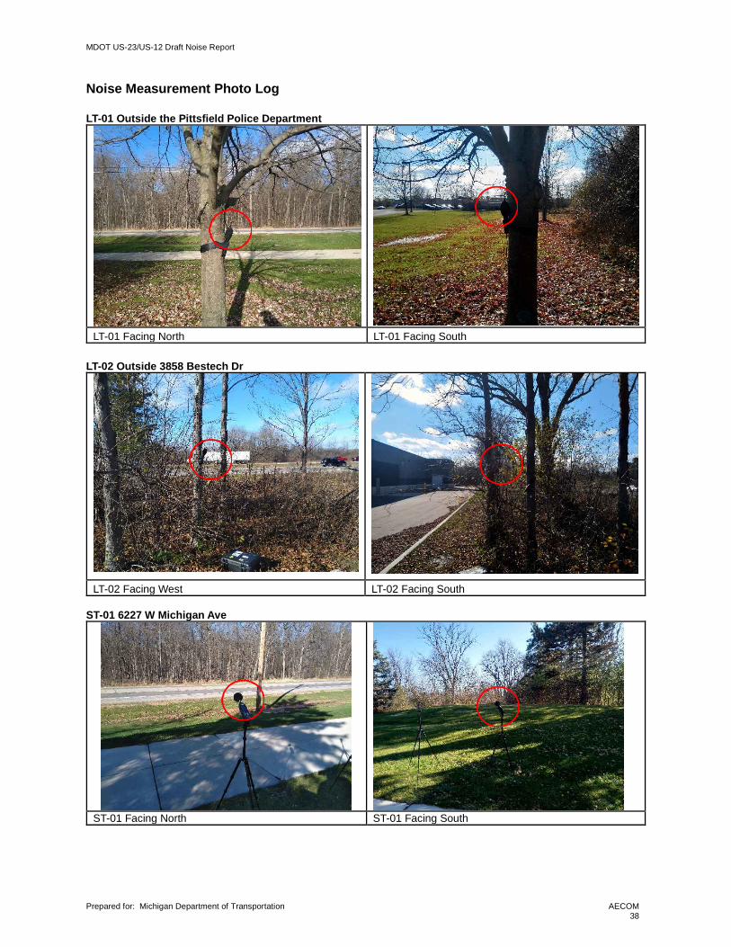
MDOT US-23/US-12 Draft Noise Report
Prepared for: Michigan Department of Transportation
AECOM 38
Noise Measurement Photo Log LT-01 Outside the Pittsfield Police Department
LT-01 Facing North LT-01 Facing South LT-02 Outside 3858 Bestech Dr
LT-02 Facing West LT-02 Facing South ST-01 6227 W Michigan Ave
ST-01 Facing North ST-01 Facing South

MDOT US-23/US-12 Draft Noise Report
Prepared for: Michigan Department of Transportation
AECOM 39
ST-02 3350 Textile Road
ST-02 Facing North East ST-02 Facing South ST-03 5807 Hampshire Ln
ST-03 Facing South ST-03 Facing North ST-04 5495 W Michigan Ave
ST-04 Facing West ST-04 Facing East

MDOT US-23/US-12 Draft Noise Report
Prepared for: Michigan Department of Transportation
AECOM 40
ST-05 3858 Bestech Dr
ST-05 Facing West ST-05 Facing East ST-06 3667 E Morgan Rd
ST-06 Facing East ST-06 Facing West

MDOT US-23/US-12 Draft Noise Report
Prepared for: Michigan Department of Transportation
AECOM 41
Field Data Sheets

MDOT US-23/US-12 Draft Noise Report
Prepared for: Michigan Department of Transportation
AECOM 42

MDOT US-23/US-12 Draft Noise Report
Prepared for: Michigan Department of Transportation
AECOM 43

MDOT US-23/US-12 Draft Noise Report
Prepared for: Michigan Department of Transportation
AECOM 44
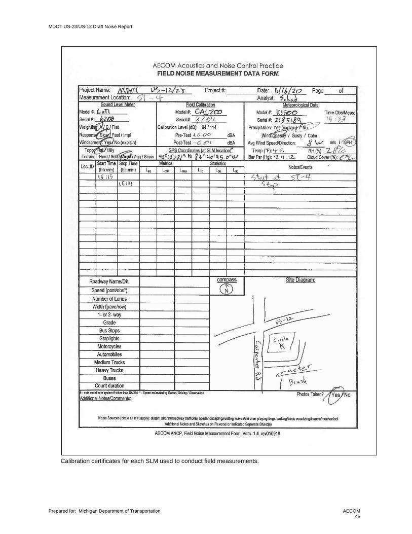
MDOT US-23/US-12 Draft Noise Report
Prepared for: Michigan Department of Transportation
AECOM 45
Calibration certificates for each SLM used to conduct field measurements.

MDOT US-23/US-12 Draft Noise Report
Prepared for: Michigan Department of Transportation
AECOM 46

MDOT US-23/US-12 Draft Noise Report
Prepared for: Michigan Department of Transportation
AECOM 47
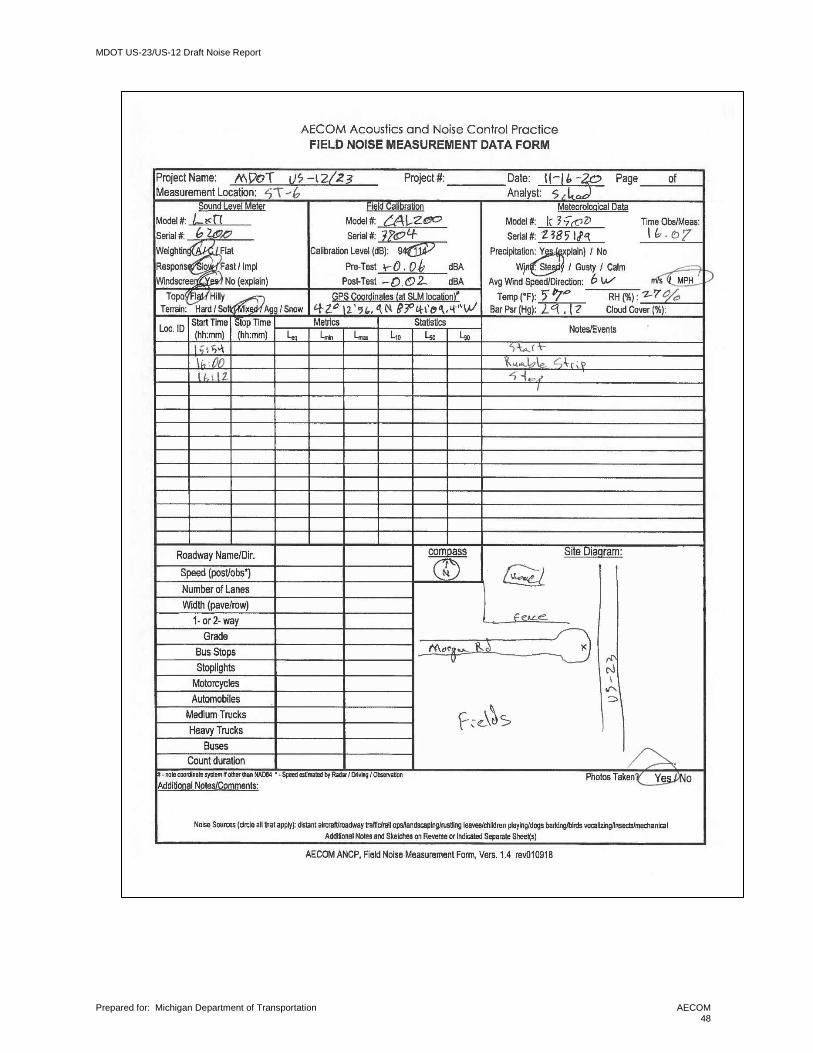
MDOT US-23/US-12 Draft Noise Report
Prepared for: Michigan Department of Transportation
AECOM 48

MDOT US-23/US-12 Draft Noise Report
Prepared for: Michigan Department of Transportation
AECOM 49
Equipment Calibration Certificates
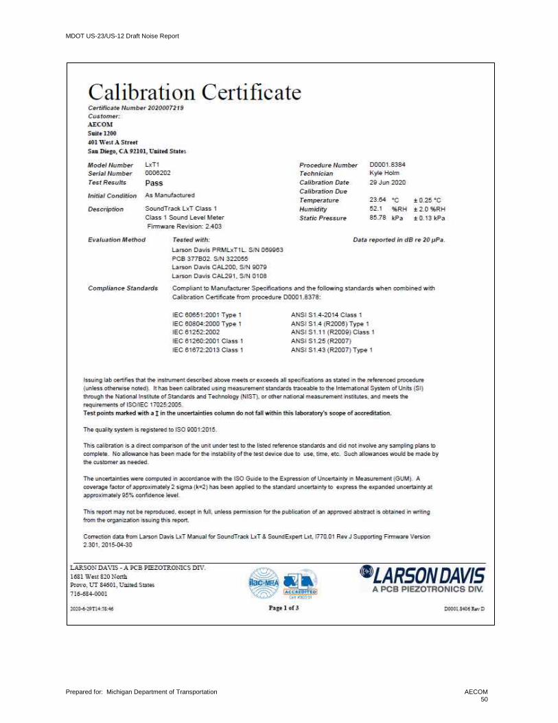
MDOT US-23/US-12 Draft Noise Report
Prepared for: Michigan Department of Transportation
AECOM 50
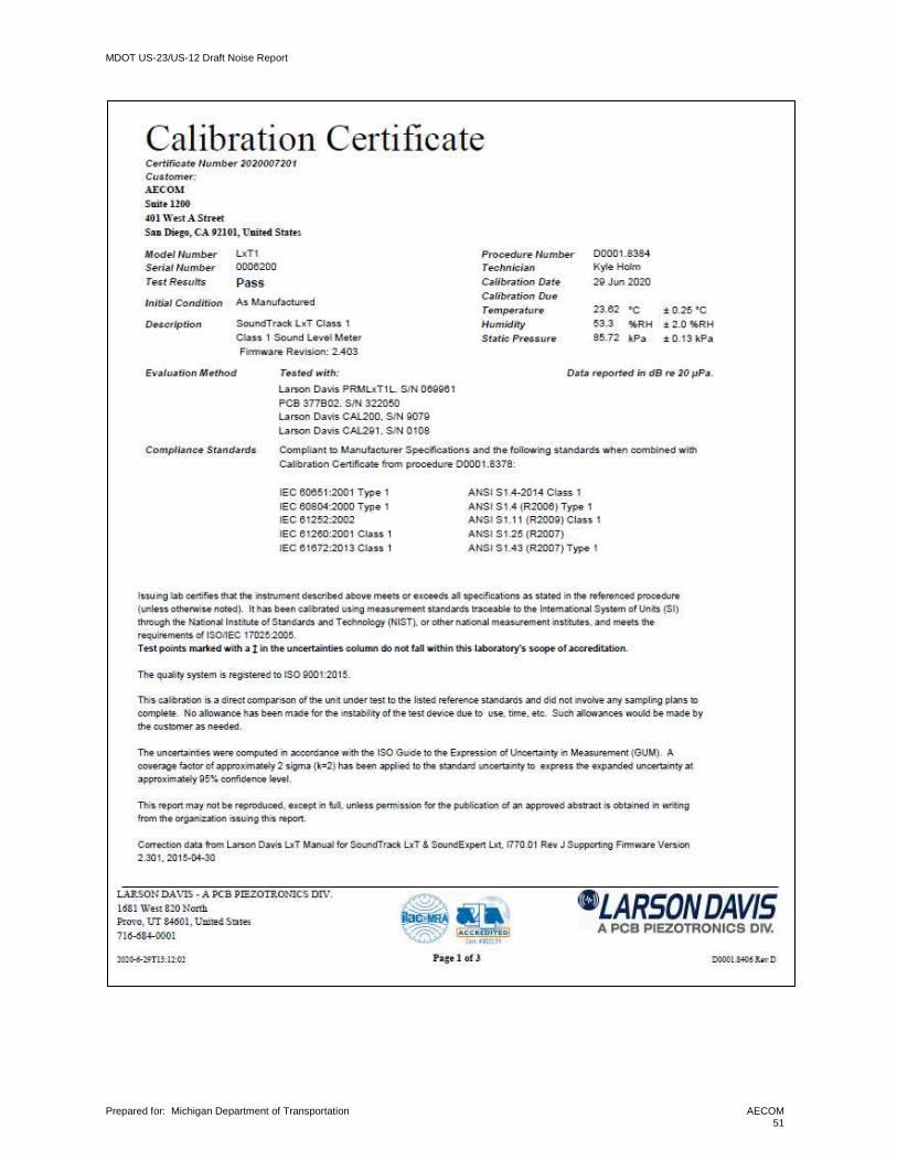
MDOT US-23/US-12 Draft Noise Report
Prepared for: Michigan Department of Transportation
AECOM 51

MDOT US-23/US-12 Draft Noise Report
Prepared for: Michigan Department of Transportation
AECOM 52

MDOT US-23/US-12 Draft Noise Report
Prepared for: Michigan Department of Transportation
AECOM 53
Appendix B Sample TNM Input/Output Files Sample TNM output tables are provided for CNE 1 Abatement analysis. Additional input and output files are available upon request.
CNE 1 TNM Sound Level Prediction Output Table
Plan View

MDOT US-23/US-12 Draft Noise Report
Prepared for: Michigan Department of Transportation
AECOM 54
Barrier Analysis Screenshot
Barrier Description Table

MDOT US-23/US-12 Draft Noise Report
Prepared for: Michigan Department of Transportation
AECOM 55
Appendix C Predicted Noise Levels and Impacts Table C-1 Loudest Hour Noise Levels, Leq(1h), dBA
Receptor Number Land Use Activity
Category Units FHWA/MDOT NAC Existing Build Change
CNE 1 1001 Public Building C 1 67 65 67 +2 1002 Residential B 1 67 53 53 +0 1003 Residential B 1 67 54 54 +0 1004 Residential B 1 67 56 56 0 1005 Residential B 1 67 57 57 0 1006 Residential B 1 67 53 53 0 1007 Residential B 1 67 54 54 0 1008 Residential B 1 67 54 53 0 1009 Residential B 1 67 56 56 0 1010 Residential B 1 67 62 62 +0 1011 Residential B 1 67 67 67 +0 1012 Residential B 1 67 70 70 +0 1013 Residential B 1 67 66 66 0 1014 Residential B 1 67 60 60 0 1015 Residential B 1 67 62 61 0 1016 Residential B 1 67 64 64 0 1017 Residential B 1 67 65 66 +0 1020 Residential B 1 67 66 66 0 1021 Residential B 1 67 66 66 0 1022 Residential B 1 67 65 65 0 1023 Residential B 1 67 65 65 0 1024 Residential B 1 67 63 63 0 1025 Residential B 1 67 62 62 0 1026 Residential B 1 67 59 59 0
CNE 2 2047 Commercial E 1 71 58 58 +1 2048 Residential B 1 67 64 65 +1 2049 Residential B 1 67 72 72 +0 2050 Church C 1 67 62 63 +1 2051 Residential B 1 67 68 68 +1 2052 Residential B 1 67 68 69 +1 2053 Residential B 1 67 67 68 +1 2054 Residential B 1 67 59 59 +1 2055 Residential B 1 67 58 59 +0 2056 Residential B 1 67 72 72 +0 2057 Residential B 1 67 72 72 +0 2058 Residential B 1 67 65 66 +0
CNE 3 3001 Residential B 1 67 60 61 +1 3002 Residential B 1 67 61 62 +1 3003 Residential B 1 67 60 60 +0 3004 Residential B 1 67 61 62 +1 3005 Residential B 1 67 70 71 +1 3006 Residential B 1 67 71 72 +1 3007 Residential B 1 67 54 54 +1 3008 Residential B 1 67 55 55 +0 3009 Residential B 1 67 55 55 +0 3101 Residential B 1 67 54 55 +0 3102 Residential B 1 67 55 55 +0 3103 Residential B 1 67 55 55 +0 3104 Residential B 1 67 55 55 +0 3105 Residential B 1 67 55 56 +0 3106 Residential B 1 67 55 55 +0
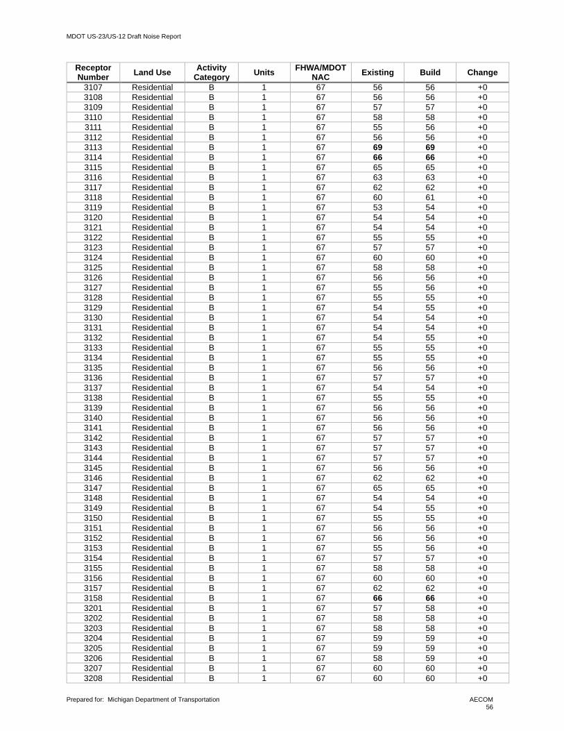
MDOT US-23/US-12 Draft Noise Report
Prepared for: Michigan Department of Transportation
AECOM 56
Receptor Number Land Use Activity
Category Units FHWA/MDOT NAC Existing Build Change
3107 Residential B 1 67 56 56 +0 3108 Residential B 1 67 56 56 +0 3109 Residential B 1 67 57 57 +0 3110 Residential B 1 67 58 58 +0 3111 Residential B 1 67 55 56 +0 3112 Residential B 1 67 56 56 +0 3113 Residential B 1 67 69 69 +0 3114 Residential B 1 67 66 66 +0 3115 Residential B 1 67 65 65 +0 3116 Residential B 1 67 63 63 +0 3117 Residential B 1 67 62 62 +0 3118 Residential B 1 67 60 61 +0 3119 Residential B 1 67 53 54 +0 3120 Residential B 1 67 54 54 +0 3121 Residential B 1 67 54 54 +0 3122 Residential B 1 67 55 55 +0 3123 Residential B 1 67 57 57 +0 3124 Residential B 1 67 60 60 +0 3125 Residential B 1 67 58 58 +0 3126 Residential B 1 67 56 56 +0 3127 Residential B 1 67 55 56 +0 3128 Residential B 1 67 55 55 +0 3129 Residential B 1 67 54 55 +0 3130 Residential B 1 67 54 54 +0 3131 Residential B 1 67 54 54 +0 3132 Residential B 1 67 54 55 +0 3133 Residential B 1 67 55 55 +0 3134 Residential B 1 67 55 55 +0 3135 Residential B 1 67 56 56 +0 3136 Residential B 1 67 57 57 +0 3137 Residential B 1 67 54 54 +0 3138 Residential B 1 67 55 55 +0 3139 Residential B 1 67 56 56 +0 3140 Residential B 1 67 56 56 +0 3141 Residential B 1 67 56 56 +0 3142 Residential B 1 67 57 57 +0 3143 Residential B 1 67 57 57 +0 3144 Residential B 1 67 57 57 +0 3145 Residential B 1 67 56 56 +0 3146 Residential B 1 67 62 62 +0 3147 Residential B 1 67 65 65 +0 3148 Residential B 1 67 54 54 +0 3149 Residential B 1 67 54 55 +0 3150 Residential B 1 67 55 55 +0 3151 Residential B 1 67 56 56 +0 3152 Residential B 1 67 56 56 +0 3153 Residential B 1 67 55 56 +0 3154 Residential B 1 67 57 57 +0 3155 Residential B 1 67 58 58 +0 3156 Residential B 1 67 60 60 +0 3157 Residential B 1 67 62 62 +0 3158 Residential B 1 67 66 66 +0 3201 Residential B 1 67 57 58 +0 3202 Residential B 1 67 58 58 +0 3203 Residential B 1 67 58 58 +0 3204 Residential B 1 67 59 59 +0 3205 Residential B 1 67 59 59 +0 3206 Residential B 1 67 58 59 +0 3207 Residential B 1 67 60 60 +0 3208 Residential B 1 67 60 60 +0
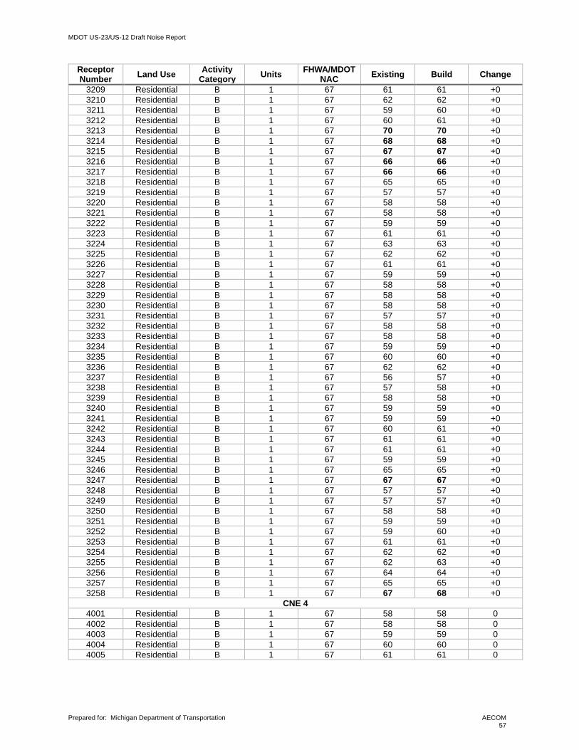
MDOT US-23/US-12 Draft Noise Report
Prepared for: Michigan Department of Transportation
AECOM 57
Receptor Number Land Use Activity
Category Units FHWA/MDOT NAC Existing Build Change
3209 Residential B 1 67 61 61 +0 3210 Residential B 1 67 62 62 +0 3211 Residential B 1 67 59 60 +0 3212 Residential B 1 67 60 61 +0 3213 Residential B 1 67 70 70 +0 3214 Residential B 1 67 68 68 +0 3215 Residential B 1 67 67 67 +0 3216 Residential B 1 67 66 66 +0 3217 Residential B 1 67 66 66 +0 3218 Residential B 1 67 65 65 +0 3219 Residential B 1 67 57 57 +0 3220 Residential B 1 67 58 58 +0 3221 Residential B 1 67 58 58 +0 3222 Residential B 1 67 59 59 +0 3223 Residential B 1 67 61 61 +0 3224 Residential B 1 67 63 63 +0 3225 Residential B 1 67 62 62 +0 3226 Residential B 1 67 61 61 +0 3227 Residential B 1 67 59 59 +0 3228 Residential B 1 67 58 58 +0 3229 Residential B 1 67 58 58 +0 3230 Residential B 1 67 58 58 +0 3231 Residential B 1 67 57 57 +0 3232 Residential B 1 67 58 58 +0 3233 Residential B 1 67 58 58 +0 3234 Residential B 1 67 59 59 +0 3235 Residential B 1 67 60 60 +0 3236 Residential B 1 67 62 62 +0 3237 Residential B 1 67 56 57 +0 3238 Residential B 1 67 57 58 +0 3239 Residential B 1 67 58 58 +0 3240 Residential B 1 67 59 59 +0 3241 Residential B 1 67 59 59 +0 3242 Residential B 1 67 60 61 +0 3243 Residential B 1 67 61 61 +0 3244 Residential B 1 67 61 61 +0 3245 Residential B 1 67 59 59 +0 3246 Residential B 1 67 65 65 +0 3247 Residential B 1 67 67 67 +0 3248 Residential B 1 67 57 57 +0 3249 Residential B 1 67 57 57 +0 3250 Residential B 1 67 58 58 +0 3251 Residential B 1 67 59 59 +0 3252 Residential B 1 67 59 60 +0 3253 Residential B 1 67 61 61 +0 3254 Residential B 1 67 62 62 +0 3255 Residential B 1 67 62 63 +0 3256 Residential B 1 67 64 64 +0 3257 Residential B 1 67 65 65 +0 3258 Residential B 1 67 67 68 +0
CNE 4 4001 Residential B 1 67 58 58 0 4002 Residential B 1 67 58 58 0 4003 Residential B 1 67 59 59 0 4004 Residential B 1 67 60 60 0 4005 Residential B 1 67 61 61 0

MDOT US-23/US-12 Draft Noise Report
Prepared for: Michigan Department of Transportation
AECOM 58
Receptor Number
Land Use Activity Category
Units FHWA/MDOT NAC
Existing Build Change
CNE 6 6001 Residential B 1 67 68 68 0
CNE 7 7001 Residential B 1 67 67 68 0 7002 Residential B 1 67 64 65 0 7003 Residential B 1 67 64 64 0 7004 Residential B 1 67 68 69 0 7005 Residential B 1 67 75 75 0
CNE 8 8001 Residential B 1 67 67 68 0 8002 Residential B 1 67 64 65 0 8003 Residential B 1 67 71 71 0
Note: Bolded values represent noise impacts.

MDOT US-23/US-12 Draft Noise Report
Prepared for: Michigan Department of Transportation
AECOM 59
Appendix D Noise Barrier Analysis Detail Table D-1 Noise Barrier Analysis, Receiver Level Detail
Receptor Number Land Use Category Units FHWA/MDOT
NAC Build Noise Level w/Barr
Noise Reduction Benefit?
Wall 1A 1006 Residential B 1 67 53 52 1 1007 Residential B 1 67 54 52 2 1008 Residential B 1 67 53 52 2 1009 Residential B 1 67 56 55 1 1010 Residential B 1 67 62 60 2 1011 Residential B 1 67 67 61 7 Y 1012 Residential B 1 67 70 60 10 Y 1013 Residential B 1 67 66 57 9 Y 1014 Residential B 1 67 60 55 6 Y 1015 Residential B 1 67 61 55 7 Y 1016 Residential B 1 67 64 58 6 Y 1017 Residential B 1 67 66 61 5 Y
Wall 1B 1020 Residential B 1 67 66 61 5 Y 1021 Residential B 1 67 66 59 7 Y 1022 Residential B 1 67 65 58 7 Y 1023 Residential B 1 67 65 60 5 Y 1024 Residential B 1 67 63 61 2 1025 Residential B 1 67 62 61 1 1026 Residential B 1 67 60 59 1
Wall 3A 3142 Residential B 1 67 57 55 2 3143 Residential B 1 67 57 55 2 3144 Residential B 1 67 57 56 2 3145 Residential B 1 67 56 55 1 3146 Residential B 1 67 62 58 5 Y 3147 Residential B 1 67 65 59 6 Y 3153 Residential B 1 67 56 53 2 3154 Residential B 1 67 57 54 3 3155 Residential B 1 67 58 55 4 3156 Residential B 1 67 60 56 5 Y 3157 Residential B 1 67 62 56 6 Y 3158 Residential B 1 67 66 57 9 Y 3242 Residential B 1 67 61 58 2 3243 Residential B 1 67 61 59 2 3244 Residential B 1 67 61 59 2 3245 Residential B 1 67 59 59 1 3246 Residential B 1 67 65 61 4 3247 Residential B 1 67 67 61 6 Y 3253 Residential B 1 67 61 59 2 3254 Residential B 1 67 62 59 3 3255 Residential B 1 67 63 60 3 3256 Residential B 1 67 64 60 4 3257 Residential B 1 67 65 60 5 Y 3258 Residential B 1 67 68 60 8 Y

MDOT US-23/US-12 Draft Noise Report
Prepared for: Michigan Department of Transportation
AECOM 60
Receptor Number Land Use Category Units FHWA/MDOT
NAC Build Noise Level w/Barr
Noise Reduction Benefit?
Wall 3B 3110 Residential B 1 67 58 54 4 3113 Residential B 1 67 69 59 10 Y 3114 Residential B 1 67 66 57 9 Y 3115 Residential B 1 67 65 57 8 Y 3116 Residential B 1 67 63 56 7 Y 3117 Residential B 1 67 62 56 6 Y 3118 Residential B 1 67 61 55 5 Y 3119 Residential B 1 67 54 52 1 3120 Residential B 1 67 54 53 2 3121 Residential B 1 67 54 53 2 3122 Residential B 1 67 55 53 2 3123 Residential B 1 67 57 56 1 3124 Residential B 1 67 60 58 2 3125 Residential B 1 67 58 56 2 3136 Residential B 1 67 57 56 2 3210 Residential B 1 67 62 58 4 3213 Residential B 1 67 70 61 9 Y 3214 Residential B 1 67 68 59 9 Y 3215 Residential B 1 67 67 59 8 Y 3216 Residential B 1 67 66 59 7 Y 3217 Residential B 1 67 66 59 6 Y 3218 Residential B 1 67 65 59 6 Y 3219 Residential B 1 67 57 57 1 3220 Residential B 1 67 58 57 1 3221 Residential B 1 67 58 57 1 3222 Residential B 1 67 59 58 1 3223 Residential B 1 67 61 60 1 3224 Residential B 1 67 63 62 2 3225 Residential B 1 67 62 60 2 3236 Residential B 1 67 62 60 2
Wall 7 7001 Residential B 1 67 68 61 7 Y 7002 Residential B 1 67 65 58 7 Y 7003 Residential B 1 67 64 60 4 7004 Residential B 1 67 69 62 7 Y 7005 Residential B 1 67 75 62 13 Y
Wall 8 8001 Residential B 1 67 68 60 8 Y 8002 Residential B 1 67 65 58 7 Y 8003 Residential B 1 67 71 61 10 Y