mda - siemens ag mda 5.8 test program testsrv.exe 5-5 5.9 conversion program mdeconvertdbs.exe 5-9...
TRANSCRIPT

MDA
Customizing Edition 04/2005
Archiving History
Machine Data Acquisition
Machine Data Evaluation

Customizing MDA

1 General
2Standard Software for Production Automation
Customizing
MDA 3Interfaces
Customizing
4Softwareupdate for MDA workstations
5Tips & Tricks
6Glossary
Edition 04/2005
Customizing MDA
Trademark
® is a registered trademark of Siemens SIMATIC
OPC™ (OLE for Process Control) is a trademark of the OPC Foundation®
Customizing MDA
Table of Contents
1 General.............................................................................................. 1-1
1.1 References .......................................................................................................... 1-1
1.2 MDA Components ............................................................................................... 1-2
1.2.1 System overview............................................................................................... 1-2
1.2.2 Server ............................................................................................................... 1-3
1.2.3 Workstation....................................................................................................... 1-5
2 Customizing....................................................................................... 2-1
2.1 General Parameters ............................................................................................ 2-3
2.2 Configuring "Groupings" ...................................................................................... 2-3
2.3 Customizing Machines/Units ............................................................................... 2-4
2.3.1 Multiple Machines ............................................................................................. 2-7
2.4 Customizing User Rights ..................................................................................... 2-8
2.5 Customizing MDA status conditions .................................................................. 2-10
2.6 Customizing alarms (MMC) ............................................................................... 2-12
2.6.1 Read in Alarm texts at workstation ................................................................. 2-12
2.6.2 Central administration of alarm texts .............................................................. 2-13
2.6.3 Multiple Machines ........................................................................................... 2-13
2.7 Customizing OEE Indicators.............................................................................. 2-14
2.8 Customizing the Works Calendar ...................................................................... 2-14
2.9 Customizing the Plant Layout ............................................................................ 2-15
2.10 Overview of Important General Parameters ................................................... 2-16
2.11 Data Transfer.................................................................................................. 2-19
2.11.1 Customizing Data Transfer .......................................................................... 2-21
2.11.2 Downloading Configuration Data ................................................................. 2-21
2.11.3 Overview Transfer Orders ........................................................................... 2-22
2.12 Configuration variants..................................................................................... 2-24
2.13 Integration of Reports into the MDA environment........................................... 2-25
I&S IS E&C MES AC 13 © Siemens AG 2005 All Rights Reserved i

Customizing MDA
3 Interfaces........................................................................................... 3-1
3.1 Cluster Data Structures ....................................................................................... 3-2
3.1.1 Structure of MDC Cluster.................................................................................. 3-2
3.1.2 Structure of PDC Cluster .................................................................................. 3-5
3.2 PnP Interface (SINUMERIK)................................................................................ 3-6
3.3 PLC Interface Machine (SINUMERIK) ................................................................. 3-8
3.4 PLC Interface Multiple Machines (SINUMERIK)................................................ 3-11
3.5 OPC Interface (ProTool/Pro) ............................................................................. 3-14
3.6 Overview............................................................................................................ 3-16
4 Software update / First commissioning of MDA workstations............ 4-1
4.1 Preparatories on the MDA Server........................................................................ 4-1
4.2 Preparations on the Workstations........................................................................ 4-2
4.3 Remote-Controlling the Workstations .................................................................. 4-3
4.4 Updating the Software via the Transfer Directory ................................................ 4-5
4.4.1 Transferring the project specific or new programs............................................ 4-5
4.4.2 Resolution of computer names in the network.................................................. 4-6
4.4.3 User Interface in Master Control....................................................................... 4-7
4.4.4 Applying the Configuration of MDA server........................................................ 4-8
4.4.5 Further Procedure............................................................................................. 4-8
4.4.6 Software update of MDA start program ............................................................ 4-9
5 Tips & Tricks...................................................................................... 5-1
5.1 Help Files............................................................................................................. 5-1
5.2 Hardcopies .......................................................................................................... 5-1
5.3 Plant model with shifted machine symbols .......................................................... 5-1
5.4 Missing Write Permissions as of Windows 2000 / Windows XP .......................... 5-1
5.5 No data transfer to / from MDA server by “MdeTransfer” .................................... 5-2
5.5.1 Access to shared directory ............................................................................... 5-2
5.5.2 Wrong configuration variant of workstation....................................................... 5-2
5.6 There is no logbook data sent to the MDA server................................................ 5-3
5.7 Workstations are extremely slow if there is no connection to the server ............. 5-4
I&S IS E&C MES AC 13 ii © Siemens AG 2005 All Rights Reserved
Customizing MDA
5.8 Test Program TestSrv.exe................................................................................... 5-5
5.9 Conversion Program MdeConvertDbs.exe .......................................................... 5-9
5.10 Diagnostic Tools ............................................................................................... 5-9
5.11 Database Tools............................................................................................... 5-10
5.11.1 General........................................................................................................ 5-10
5.11.2 Oracle .......................................................................................................... 5-10
5.12 Backup of customer’s database and restoring on a diagnostic computer ....... 5-11
5.12.1 Database files from SQL Server or MSDE................................................... 5-11
5.12.2 Oracle .......................................................................................................... 5-11
5.12.3 Using the database Microsoft Access.......................................................... 5-11
5.13 Extending Database ....................................................................................... 5-11
5.14 Computer names modified (Master CD with ghost image) ............................. 5-12
5.14.1 Computer name of the workstation self ....................................................... 5-12
5.14.2 Computer name of the MDA server ............................................................. 5-12
5.15 Computer name of the MDA Server self ......................................................... 5-13
5.16 Windows User ................................................................................................ 5-13
5.17 Password of the Windows user PDA has changed......................................... 5-13
5.18 Password of Database user PDA has changed.............................................. 5-14
5.19 Adding a new work centre on the MDA server................................................ 5-14
5.20 Changing the workstation customization on the MDA server.......................... 5-14
6 Glossary ............................................................................................ 6-1
I&S IS E&C MES AC 13 © Siemens AG 2005 All Rights Reserved iii

Customizing MDA
1 General
This document describes the customizing of MDA in all variants (Cell, Plant, IFC or Machine). For editorial reasons some functions are described which are not part of the product MDA Cell but are intended for use within projects. These chapters are to be ignored for customizing of MDA Cell.
Considering paths it is assumed in this documentation that MDA on standard PCs is installed into the directory C:\Siemens\MCIS, on MMC103 into directory c:\add_on and on PCU50 into directory f:\add_on. In the sections below this MCIS installation path is referred to as <MCISDIR> and the subdirectory MDA as <MDADIR>.
1.1 References
With reference to the following documents within the folder docu at the CD
/1/ Commissioning Guide MDA Machine, Edition 04/2005 /2/ Commissioning Guide MDA Cell, Edition 04/2005 /3/ Installation of Oracle, Edition 04/2005
I&S IS E&C MES AC 13 © Siemens AG 2005 All Rights Reserved 1-1

Customizing MDA
1.2 MDA Components
1.2.1 System overview MDA is designed for a group solution. In a Group one superordinate host (MDA Cell or MDA Plant) and several workstations (Acquisition PCs/MMCs) work together. The acquisition data of the worksta-tions are transfered to the MDA server, so centralized and comparative evaluations can be done.
I&S IS E&C MES AC 13 © Siemens AG 2005 All Rights Reserved 1-2

Customizing MDA
1.2.2 Server
MDA Cell
Link module to MDA IFC
ISM.exe MdeTransfer.exe
Start program MDAStartService.exe
Summarized data MdeCompress.exe
Acqisition- and
Configuration- database
OSFDB
Configurations ProjUser.exe ProjOEM.exe
INI-Files MdeServer.ini
MDAStartService.ini
MDA IFC MdeReport.exe
Works calendar WkalGUI.exe Part Type
Evaluations
Alarm Evaluations
Machine Evaluations
GUIRT.exe
Monitoring MonGUI.exe
I&S IS E&C MES AC 13 © Siemens AG 2005 All Rights Reserved 1-3

Customizing MDA
The MDA components have the following functionality:
The Acquisition Database contains all the dynamic data, such as the logbook, protocols, statistics and system messages..
Configuration data is stored in the Configuration Database. Among other things, this includes global configuration parameters, screen form and message texts, the structure and hierarchy of the user interface screen forms, colour definitions and user authorizations.
All customizing can be carried out using the Configuration User Interfaces ProjUser.exe and ProjOEM.exe. The ProjUser.exe planning user interface can be used to generate work centres (machines and units), MDA statuses, user groups, colour definitions etc. and modify general settings. Screen forms, table layouts and texts etc. can be modified using the ProjOEM.exe planning interface.
Shift and day types, working time models and the calendar can be defined using the Works Calendar WkalGUI.exe.
The Start Program MDAStartService.exe is used to automatically start up MDA and monitor the individual tasks. The start program uses the MDAStartService.ini, to do this, in which all programs to be started are stored.
The Compression program MdeCompress.exe generates the daily, weekly, monthly and annual statistics from the report with the acquired MDA data, PDA data and alarms. The compression program also deletes old data from the logbook and the protocols in order to limit the quantity of data in the database.
The Link module to MDA IFC MdeTransfer.exe handles the transfer of data between MDA Cell and the workstation. The planning and works calendar data can be transferred to the workstation from MDA Cell. The acquired data is transferred in the opposite direction at regular intervals. The logbook data are notified immediately to MDA Cell by MdeReport.exe and registered in the acquisition database by ISM.exe.
The User Interface GUIRT.exe is used for all Acquisition Data (Machine-, Alarm- and Part Type Data). The following Dialogs are implemented: Fault reason analyses, status analyses, availability analyses and counter evaluations. Data from the log book, the protocols and the system logbook can also be displayed. OEE indicator calculations and counter analyses for part types, protocols and statistics for part types. The part type definitions can be displayed and edited. Part type filters can be defined. Current alarms, alarm protocols and alarm statistics. Alarm filters can be defined.
The Planning Files MdeServer.ini contain basic MDA settings that are only modified for test purposes (e.g. database providers).
I&S IS E&C MES AC 13 © Siemens AG 2005 All Rights Reserved 1-4
Customizing MDA
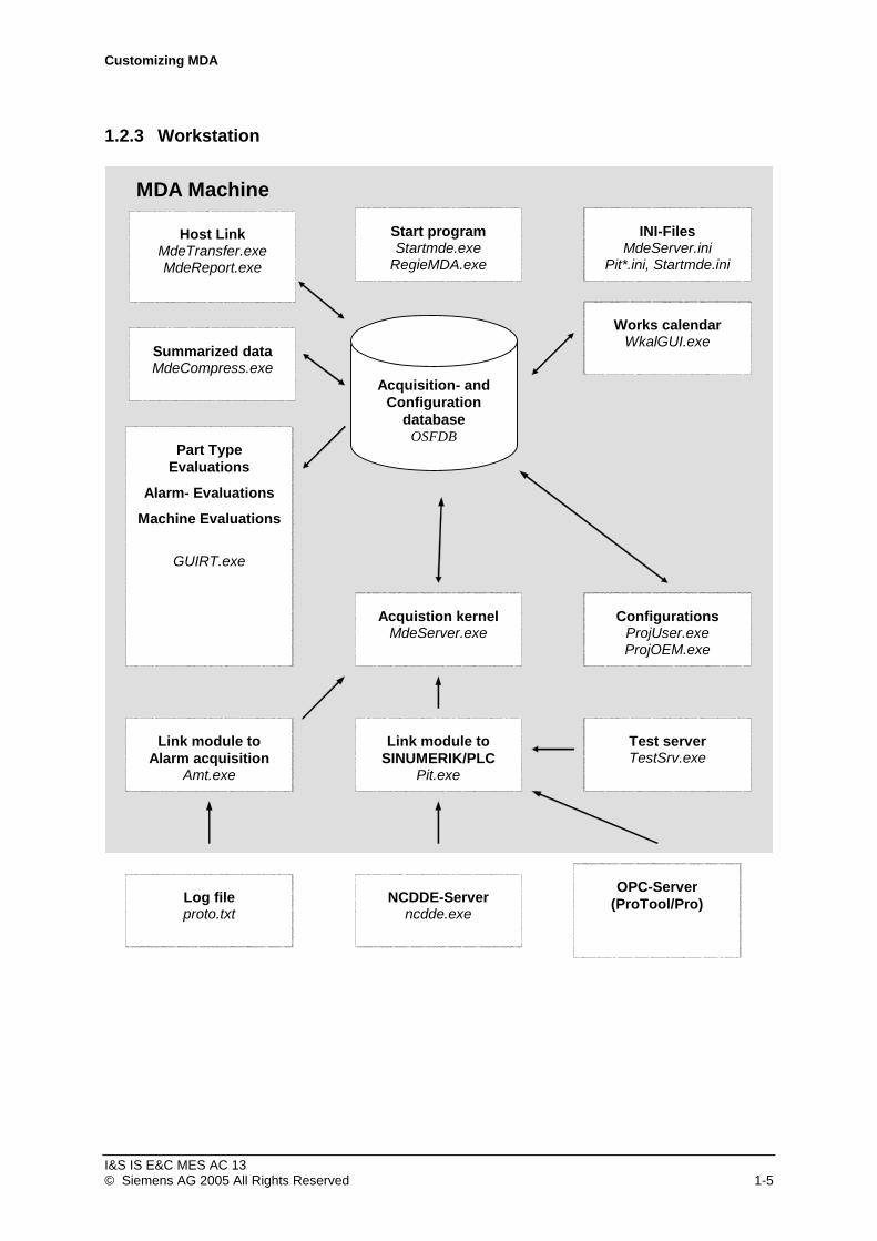
1.2.3 Workstation
MDA Machine
Acquistion kernel MdeServer.exe
Test server TestSrv.exe
Link module to SINUMERIK/PLC
Pit.exe
Start program Startmde.exe
RegieMDA.exe
Summarized data MdeCompress.exe
Acquisition- and Configuration
database OSFDB
Configurations ProjUser.exe ProjOEM.exe
INI-Files MdeServer.ini
Pit*.ini, Startmde.ini
NCDDE-Server ncdde.exe
Host Link MdeTransfer.exe MdeReport.exe
Log file proto.txt
Link module to Alarm acquisition
Amt.exe
Works calendar WkalGUI.exe
OPC-Server (ProTool/Pro)
Part Type Evaluations
Alarm- Evaluations
Machine Evaluations
GUIRT.exe
I&S IS E&C MES AC 13 © Siemens AG 2005 All Rights Reserved 1-5
Customizing MDA
The MDA components have the following functionality:
The central Database OSFDB contains the Acquisition and Configuration Databases.
The Acquisition Database contains all the dynamic data, such as the logbook, protocols, statistics and system messages. The database is backed up at regular intervals.
Configuration data is stored in the Configuration Database. Among other things, this includes global configuration parameters, screen form and message texts, the structure and hierarchy of the user interface screen forms, colour definitions and user authorizations. The database is backed up at regular intervals.
All customizing can be carried out using the Configuration User Interfaces ProjUser.exe and ProjOEM.exe. The ProjUser.exe planning user interface can be used to generate work centres (machines and units), MDA statuses, user groups, colour definitions etc. and modify general settings. Screen forms, table layouts and texts etc. can be modified using the ProjOEM.exe planning interface.
Shift and day types, working time models and the calendar can be defined using the Works Calendar WkalGUI.exe.
The Start Program Startmde.exe is used to automatically start up MDA and monitor the individual tasks. The start program uses the Startmde.ini to do this, in which all programs to be started are stored. For automatical software update the program is started via helper program RegieMDA.exe. The start program RegieMDA.exe is stored on the MMC as a start service in the [StartupConfiguration] section of file \add_on\regie.ini and takes care of a correct registration of MDA at HMI Advanced. At Standard PCs MDA may be started via the Windows Service MDAStartService.exe during system start up.
The Linking Module Pit.exe handles the automatic acquisition of MDA data (statuses, counters) and PDA data (part types). The acquisition can take place on MMC (SINUMERIK) via PLC data blocks (PLC interface) or the status variables of the NCDDE server (Plug&Play interface, only MDA statuses). PC acquisition using ProTool/Pro or WinCC can take place using PLC data blocks (PLC interface) via the OPC server. For test purposes, acquisition can also take place manually using the TestSrv.exe test programs, whereby the PLC interface is simulated.
The Linking Module Amt.exe handles the automatic acquisition of alarms from the MMC file proto.txt.
The Acquisition Kernel MdeServer.exe accepts the acquired MDA data, PDA data and alarms and stores the messages in the form of data records in the logbook, protocol and priority report. The acquisition database is backed up and compressed by the acquisition kernel at planned time intervals.
The Compression program MdeCompress.exe generates the daily, weekly, monthly and annual statistics from the report with the acquired MDA data, PDA data and alarms. The compression program also deletes old data from the logbook and the protocols in order to limit the quantity of data in the database.
The Host Coupling MdeTransfer.exe handles the transfer of data between MDA Cell and the workstation. The planning and works calendar data can be transferred to the workstation from MDA Cell. The acquired data is transferred in the opposite direction at regular intervals. The logbook data are notified immediately to MDA Cell by MdeReport.exe.
The User Interface GUIRT.exe is used for all Acquisition Data (Machine-, Alarm- and Part Type Data). The following Dialogs are implemented: Fault reason analyses, status analyses, availability analyses and counter evaluations. Data from the log book, the protocols and the system logbook can also be displayed. OEE indicator calculations and counter analyses for part types, protocols and statistics for part types. The part type definitions can be displayed and edited. Part type filters can be defined. Current alarms, alarm protocols and alarm statistics. Alarm filters can be defined.
The Planning Files Pit_*ini and MdeServer.ini contain basic MDA settings that are only modified for test purposes (e.g. database providers).
I&S IS E&C MES AC 13 © Siemens AG 2005 All Rights Reserved 1-6
Customizing MDA
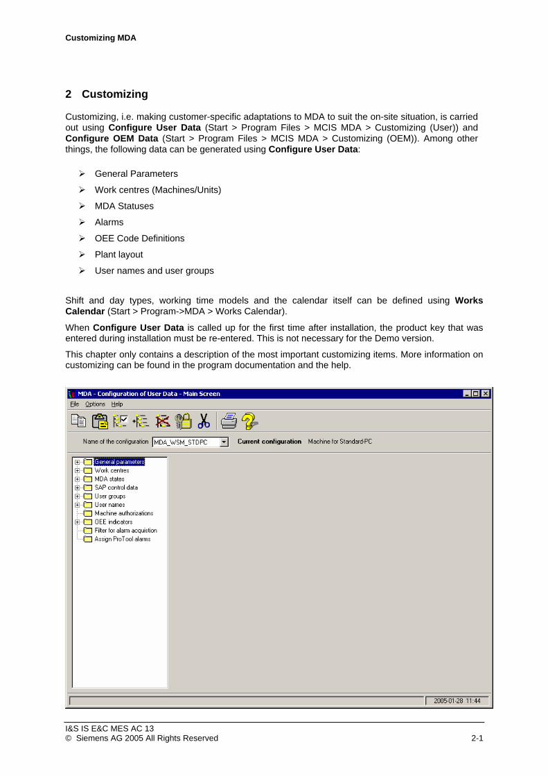
2 Customizing
Customizing, i.e. making customer-specific adaptations to MDA to suit the on-site situation, is carried out using Configure User Data (Start > Program Files > MCIS MDA > Customizing (User)) and Configure OEM Data (Start > Program Files > MCIS MDA > Customizing (OEM)). Among other things, the following data can be generated using Configure User Data:
General Parameters
Work centres (Machines/Units)
MDA Statuses
Alarms
OEE Code Definitions
Plant layout
User names and user groups
Shift and day types, working time models and the calendar itself can be defined using Works Calendar (Start > Program->MDA > Works Calendar).
When Configure User Data is called up for the first time after installation, the product key that was entered during installation must be re-entered. This is not necessary for the Demo version.
This chapter only contains a description of the most important customizing items. More information on customizing can be found in the program documentation and the help.
I&S IS E&C MES AC 13 © Siemens AG 2005 All Rights Reserved 2-1
Customizing MDA
The user interface can be moved and the size changed using the mouse and the keyboard. The following entries in the window menu can be called up using the "ALT + Space bar" key combination:
Menu item Function
Undo Undoes previous action
Move Allows the user interface to be moved using the cursor keys
Resize Allows the size of the user interface to be adapted using the cursor keys
Minimize Closes the application window without terminating the program
Maximize Full screen display
I&S IS E&C MES AC 13 © Siemens AG 2005 All Rights Reserved 2-2

Customizing MDA
2.1 General Parameters
Global and application-specific parameters can be modified using General Parameters (e.g. GUI_RT, MDE_COMPRESS, MDE_SERVER, PIT, MDE_TRANSFER). A new configuration can be created from an existing configuration in the main screen form by copying and used as the current configuration for test purposes, for example.
Among other things, the General Parameters can be used to configure which data is acquired and whether the data is acquired with/without the works calendar.
2.2 Configuring "Groupings"
For the multistage mimic screen and for future evaluations in MDA, you can define groupings and assign each machine to these groupings: machines can be assigned to an area and a group, to a cost center, to a manufacturer and to a machine type.
I&S IS E&C MES AC 13 © Siemens AG 2005 All Rights Reserved 2-3

Customizing MDA
2.3 Customizing Machines/Units
The unique key for a machine / unit consists of the plant, PDA group and machine part keys. This three-part key is assigned to a unique work centre number within MDA. MDA uses the work centre number internally, and the three-part key is for display purposes only.
Notice: New work centres on the MDA server only get effective for the data acquisition interface to the workstations if the MDA start service is finished and started newly because the program ISM uses a machine list internally.
The first entry is produced by selecting the Work centres folder in the tree display.
Other entries can be produced by first displaying the data for an existing entry. Operating button F3 ("Create New Machine”) creates a new entry using the data from the previously selected entry.
After an individual machine / unit has been selected in the tree display, the work centre data can be entered or modified using the tabs on the right-hand side of the screen.
“Identification“ Tab
The work centre number (APLZ No.), the three-part key for display purposes and the designation are entered using the “Identification“ tab. It must then be specified whether it is a machine (“Main Unit“) or Unit. In the latter case the unit must be assigned to a machine. If there are more than one machines/units at a SINUMERIK, the NCU name has to be entered. If only one NCU exists the field may be empty. The NCU name will not be checked during acquisition then. The work centre number can only be entered when the work centre is created. The Plant and PDA Group key parts can also only be entered during creation at present.
I&S IS E&C MES AC 13 © Siemens AG 2005 All Rights Reserved 2-4
Customizing MDA
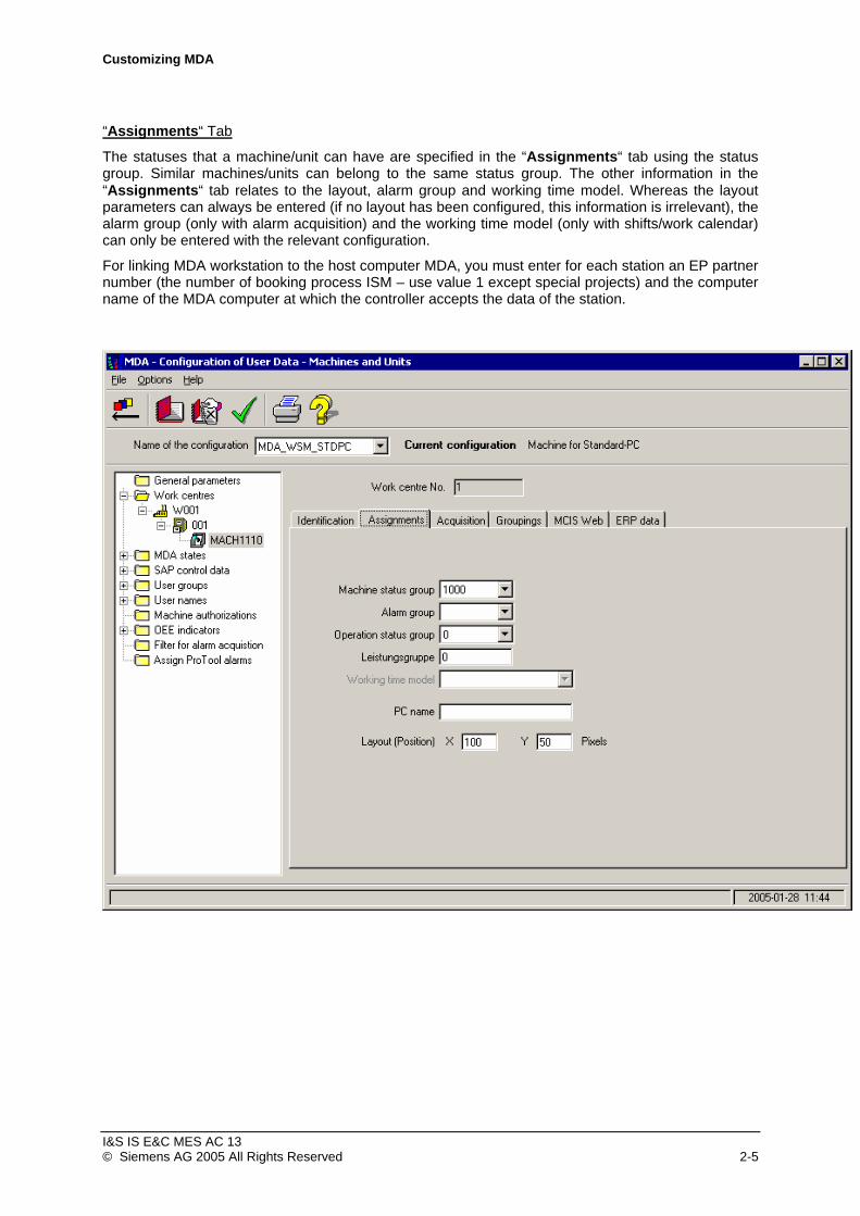
“Assignments“ Tab
The statuses that a machine/unit can have are specified in the “Assignments“ tab using the status group. Similar machines/units can belong to the same status group. The other information in the “Assignments“ tab relates to the layout, alarm group and working time model. Whereas the layout parameters can always be entered (if no layout has been configured, this information is irrelevant), the alarm group (only with alarm acquisition) and the working time model (only with shifts/work calendar) can only be entered with the relevant configuration.
For linking MDA workstation to the host computer MDA, you must enter for each station an EP partner number (the number of booking process ISM – use value 1 except special projects) and the computer name of the MDA computer at which the controller accepts the data of the station.
I&S IS E&C MES AC 13 © Siemens AG 2005 All Rights Reserved 2-5

Customizing MDA
“Acquisition “Tab
The “Acquisition“ tab is used to determine whether MDA and/or PDA data is to be acquired by se-lecting the type of automatic acquisition. For the PLC interface, the relevant data areas are addressed using the Cluster and Position parameters (see in chapter 3 the sections “PLC Interface Machine (SINUMERIK)“, “OPC Interface (ProTool/Pro)”).
I&S IS E&C MES AC 13 © Siemens AG 2005 All Rights Reserved 2-6
Customizing MDA
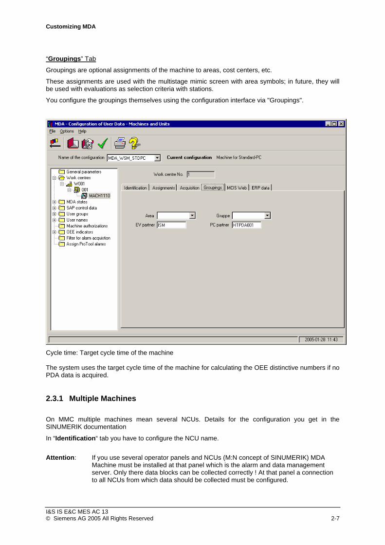
“Groupings” Tab
Groupings are optional assignments of the machine to areas, cost centers, etc.
These assignments are used with the multistage mimic screen with area symbols; in future, they will be used with evaluations as selection criteria with stations.
You configure the groupings themselves using the configuration interface via "Groupings".
Cycle time: Target cycle time of the machine The system uses the target cycle time of the machine for calculating the OEE distinctive numbers if no PDA data is acquired.
2.3.1 Multiple Machines
On MMC multiple machines mean several NCUs. Details for the configuration you get in the SINUMERIK documentation
In “Identification“ tab you have to configure the NCU name.
Attention: If you use several operator panels and NCUs (M:N concept of SINUMERIK) MDA Machine must be installed at that panel which is the alarm and data management server. Only there data blocks can be collected correctly ! At that panel a connection to all NCUs from which data should be collected must be configured.
I&S IS E&C MES AC 13 © Siemens AG 2005 All Rights Reserved 2-7

Customizing MDA
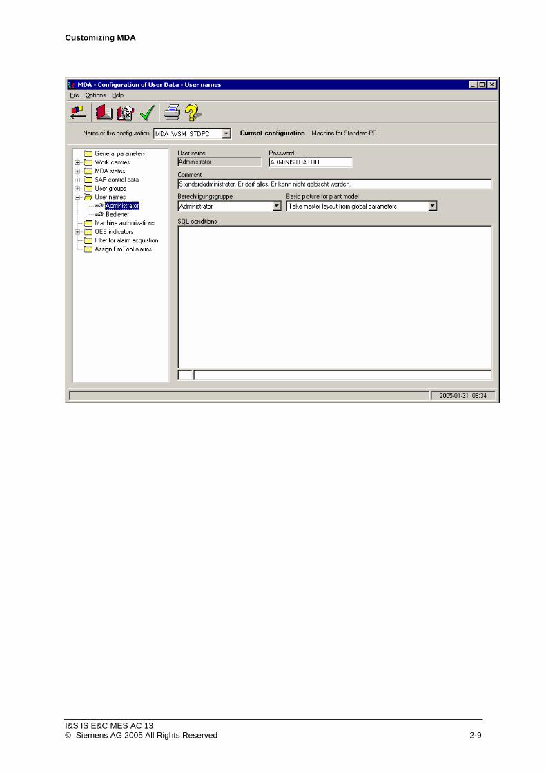
2.4 Customizing User Rights
MDA works with a user administration analogous to that of Windows allowing different users to log on. These users belong to a user group. These in turn have various priviliges. The user groups are estab-lished independent of the chosen configuration. For every user interface various access privileges can be assigned to the user group. Every privilege applies to a screen form or a function and determines whether the respective user group is allowed to utilize this screen form or function.
I&S IS E&C MES AC 13 © Siemens AG 2005 All Rights Reserved 2-8
Customizing MDA
I&S IS E&C MES AC 13 © Siemens AG 2005 All Rights Reserved 2-9

Customizing MDA
2.5 Customizing MDA status conditions
Every machine and every unit is assigned to a status group. In a status group, you must define all the MDA status conditions that a machine or a unit can have. In principle, you can define a separate status group for each machine/unit. However, it is more practical to assign similar machines/units to the same status group reduce the number of configurations necessary.
Status groups and MDA statuses are produced by selecting the MDA states folder in the tree display.
Every MDA status in a status group has a unique status number, a priority, a unique symbolic name, a designation and a colour for visualization.
In the status number a main and a sub-status condition are coded. The first digits of the number are for the main status condition and the last four represent the sub-status condition. You can define up to 80 main status conditions. Higher identification areas are spared for extensions. When defining a new status group you should take into account the fact that MDA's availability analysis only runs via the main status conditions. One of the bars in the availability chart contains the times of all the status conditions that belong to a main status condition (e.g. all the disturbances). Status analysis and disturbance cause analysis can be based on main or sub-status conditions.
I&S IS E&C MES AC 13 © Siemens AG 2005 All Rights Reserved 2-10

Customizing MDA
In the symbolic name of an MDA status, the functionality is also implicitly coded. All the MDA status conditions that are to be manually acquired via the user interface must be prefixed by $MAN.
When using MDA's PLC interface (sample data in status group 1000), up to 128 status bits are possible per machine/unit. For each bit that is used, an MDA status must be defined with the prefix Bit_ in the assigned status group. To be able to configure the MDA status for the second bit in the bit strip, for example, you must generate an entry containing the symbolic name Bit_2 in the status group.
If you use MDA's plug & play interface (MMC, sample data in status group 2000), you must define six MDA status conditions that all have symbolic names prefixed NCDDE_:
Symbolic Name Mode
NCDDE_JOG JOG mode
NCDDE_MDA MDA mode
NCDDE_NCPLC NC disturbance or PLC disturbance
NCDDE_ORG Organizational disturbance
NCDDE_PLC PLC disturbance
NCDDE_PROD Production
Determining the highest priority MDA status
The priority feature allows you to regulate which MDA status has the highest priority in the event that there is more than one parallel MDA status conditions current at one time. Only the highest priority status at any one time is entered in the statistics. The lower the priority value of an MDA status, the higher its priority is. If two MDA status conditions with the same priority are current, the one that has been current the longest has the highest priority.
Internal status conditions $OFFLINE and $DEFAULT are used for status conditions machine switched off and machine status unknown. MDA assigns the lowest possible priority for these status conditions.
Manual MDA status conditions
Automatically acquired and manually entered MDA status conditions can overlap. In addition, with status conditions that are acquired manually via the MDA user interface, only one manual MDA status can be current at any one time. By implication, when choosing a new manual status, any manual status currently in the system is ended. You end the current manual MDA status without selecting a new manual MDA status by choosing $MAN_AUTO (“End manual status”).
Notice: MDA status conditions $MAN_AUTO, $OFFLINE and $DEFAULT must be defined in every status group.
I&S IS E&C MES AC 13 © Siemens AG 2005 All Rights Reserved 2-11

Customizing MDA
2.6 Customizing alarms (MMC)
Alarm acquisition and evaluation is currently only allowed for the MMC. Parameters must be set in the General parameters in order to read in alarm texts and acquire alarms (see chapter 2.1 ”General Parameters“)!
2.6.1 Read in Alarm texts at workstation
Read in Alarm Texts
In order to process alarms, the MMC alarm texts must first be read in. The alarm texts are required for correct generation and display of alarm statistics.
The Read in alarm texts menu item only appears in the File menu in Customizing(User) if the WITH_ALARM parameter has been set to “1“. The value of the WITH_ALARM parameter can be modified using the configuration ( Customizing(User) > General Parameters > Glob > WITH_ALARM ).
The alarm texts are read in using File > Read in alarm texts menu item.
The standard MMC texts are usually stored in the \dh\mb.dir directory in files al*??.com, whereby “??” represents the language code (gr = German, uk = English etc). However, other alarm text files can exist. The names of these files and the directories in which they exist is stored in the [TextFiles] section of file mbdde.ini (search order is from left to right):
„\user\mbdde.ini, \oem\mbdde.ini, \add_on\mbdde.ini, \mmc2\mbdde.ini, \hmi_adv\mbdde.ini“
I&S IS E&C MES AC 13 © Siemens AG 2005 All Rights Reserved 2-12

Customizing MDA
The following entries are required:
Alarm Group: The alarm group that was specified when the work centres were defined must be specified.
Source: Always enter MMC here.
Directory: The directory containing the alarm text files must be entered here (default: “\dh\mb.dir“).
File Filters: The alarm text files with wildcards must be entered here, e.g. “al*.com“for the alarm texts for all languages, and “al*gr.com“ or “al*uk.com“ for all German and English alarm texts.
Number of significant parameters per alarm: “0” should be entered here. Alarm texts can contain parameters, e.g. the channel number. The greater the number of relevant parameters, the greater the quantity of data in the alarm statistics.
2.6.2 Central administration of alarm texts Alternatively to reading in the alarms at he controls the alarm texts can also be imported centrally on the MDA server and subsequently be distributed via “MdeTranfer“ to the particular MDA workstations (see chapter 2.11.3, “Overview Transfer Orders”). To this the alarm texts of the S7 projects have to be exported and to be made available in a direcory on the server. The import of the alarm texts is per-formed using the program Customizing (User) in the same way as previously desrcibed.
2.6.3 Multiple Machines
On MMC multiple machines mean several NCUs. The different NCUs have to support their NCU name correctly while sending an alarm to the HMI-Base system (Details for the configuration you get in the SINUMERIK documentation).
With the user interface Customizing(User) you have to set the parameter MMCALARM.NCU_NAME to „1“ in General Settings for program AMT.
Attention: If you use several operator panels and NCUs (M:N concept of SINUMERIK) MDA Machine must be installed at that panel which is the alarm and data management server. Only there alarms can be collected correctly! At that panel a connection to all NCUs from which alarms should be collected must be configured.
I&S IS E&C MES AC 13 © Siemens AG 2005 All Rights Reserved 2-13

Customizing MDA
2.7 Customizing OEE Indicators
Calculation customizing and the display of availability and utilisation (OEE codes) is taken care of in the OEE Indicators folder in the MDA Configure User Data tree display.
In order to modify the calculation and display of the OEE indicators, expand the OEE indicators folder in the tree display and select the Calculate OEE indicators or Display OEE indicators folder.
More information on customizing OEE Indicators can be found in the MDA Configuration user guide and help.
2.8 Customizing the Works Calendar
Shift and day types, working time models and the calendar can be defined using the MDA Works Calendar program (Start > Program Files > MCIS MDA > Works Calendar). More information on customizing the works calendar can be found in the MDA Works Calendar user guide and help.
Notice: Parameters have to be set in Customizing(User) > General parameters in order to evaluate the works calendar during data acquisition (see chapter 2.1 ”General Parameters“)!
I&S IS E&C MES AC 13 © Siemens AG 2005 All Rights Reserved 2-14

Customizing MDA
2.9 Customizing the Plant Layout
Using the node plant model in the tree view of Customizing (User) the plant layout can be custom-ized.
The multi-level mimic screen is for the visualization of the status conditions of stations and areas as well as of the workpiece counters of stations in rather large installations. With MDA Cell you can use solely one level.
Each mimic screen consists of:
• a background graphic: A ".bmp" bitmap format file that you can use to load any graphic you like as the background image.
• Symbols: A symbol can display the data of a station or an area or a group.
• Successor images: For each icon , you can optionally state a successor image that you can call by double-clicking on the icon or by right-clicking on the icon and choosing "Subimage" in the context menu.
This allows you to implement hierarchical and network-like structures of mimic screens. You use the configuration to specify the following:
• Which background graphic the system loads with a mimic screen. • Which icon the system displays in the respective mimic screen. • Which station, buffer or which area/group the system visualizes with an icon. • Whether the system displays the ‘Good’, ‘Scrap’ and ‘Rework’ piece counters.
I&S IS E&C MES AC 13 © Siemens AG 2005 All Rights Reserved 2-15

Customizing MDA
• Whether the number of imported and/or exited workpieces are to be displayed at the workpiece buffer.
• Whether the system displays the status text. • Whether the system displays in image as a subimage and if so, which one. • Which magazine has been associated to the workpiece buffer.
2.10 Overview of Important General Parameters
With/without MDC data acquisition (machine states, machine counters)
The acquisition of MDC data can be activated in the customizing of work centres in the tab ‘Acquisition’.
Parameters Value Value Meaning with without
MDE_SERVER > ACQUISITION_ENABLED
1 0 General data acquisition
MDE_COMPRESS > WITH_STATE_ACQUISITION
1 0 MDA processing
MDE_COMPRESS > MAX_STATE_LOGBOOK
1000 0 3000 records, default value
MDE_COMPRESS > MAX_STATE_PRIOPROTO
1000 0 1000 records, default value
MDE_COMPRESS > MAX_STATE_PROTOCOL
1000 0 1000 records, default value
MDE_COMPRESS > MAX_STATE_SHIFTS
0 0 0 shifts, default value (always 0 without works calendar/shifts)
MDE_COMPRESS > MAX_STATE_DAYS
60 0 60 days, default value
MDE_COMPRESS > MAX_STATE_WEEKS
10 0 10 weeks, default value
MDE_COMPRESS > MAX_STATE_MONTHS
12 0 12 months, default value
MDE_COMPRESS > MAX_STATE_YEARS
3 0 3 years, default value
I&S IS E&C MES AC 13 © Siemens AG 2005 All Rights Reserved 2-16
Customizing MDA
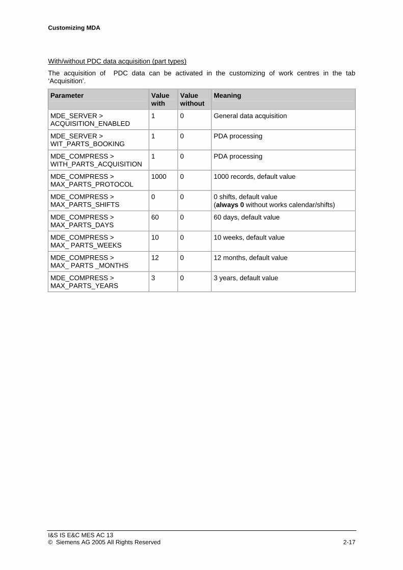
With/without PDC data acquisition (part types)
The acquisition of PDC data can be activated in the customizing of work centres in the tab ‘Acquisition’.
Parameter Value Value Meaning with without
MDE_SERVER > ACQUISITION_ENABLED
1 0 General data acquisition
MDE_SERVER > WIT_PARTS_BOOKING
1 0 PDA processing
MDE_COMPRESS > WITH_PARTS_ACQUISITION
1 0 PDA processing
MDE_COMPRESS > MAX_PARTS_PROTOCOL
1000 0 1000 records, default value
MDE_COMPRESS > MAX_PARTS_SHIFTS
0 0 0 shifts, default value (always 0 without works calendar/shifts)
MDE_COMPRESS > MAX_PARTS_DAYS
60 0 60 days, default value
MDE_COMPRESS > MAX_ PARTS_WEEKS
10 0 10 weeks, default value
MDE_COMPRESS > MAX_ PARTS _MONTHS
12 0 12 months, default value
MDE_COMPRESS > MAX_PARTS_YEARS
3 0 3 years, default value
I&S IS E&C MES AC 13 © Siemens AG 2005 All Rights Reserved 2-17

Customizing MDA
With/without alarm acquisition
Default values at installation: Without alarm acquisition and without works calendar
Parameter Value Value Meaning with without
MDE_SERVER > ACQUISITION_ENABLED
1 0 General data acquisition
MDE_SERVER > WITH_ALARM
1 0 Alarm processing
AMT > WITH_MMCALARM 1 0 MMC alarm processing
MDE_COMPRESS > WITH_ALARM_ACQUISITION
1 0 Alarm processing
MDE_COMPRESS > MAX_ALARM_LOGBOOK
3000 0 3000 records, default value
MDE_COMPRESS > MAX_ALARM_PROTOCOL
1000 0 1000 records, default value
MDE_COMPRESS > MAX_ALARM_SHIFTS
0 0 0 shifts, default value (always 0 without works calendar/shifts)
MDE_COMPRESS > MAX_ALARM_DAYS
10 0 10 days, default value
MDE_COMPRESS > MAX_ALARM_WEEKS
6 0 6 weeks, default value
MDE_COMPRESS > MAX_ALARM_MONTHS
6 0 6 months, default value
MDE_COMPRESS > MAX_ALARM_YEARS
2 0 2 years, default value
With/without works calendar/shifts
Default values at installation: Without works calendar (shifts)
Parameter Value Value Meaning with without
GLOB > WITH_SHIFT 1 0 Works calendar/shifts
MDE_COMPRESS > MAX_STATE_SHIFTS
90 0 90 shifts (e.g.)
MDE_COMPRESS > MAX_PARTS_SHIFTS
90 0 90 shifts (e.g.)
MDE_COMPRESS > MAX_ALARM_SHIFTS
10 0 10 shifts (e.g.)
I&S IS E&C MES AC 13 © Siemens AG 2005 All Rights Reserved 2-18
Customizing MDA
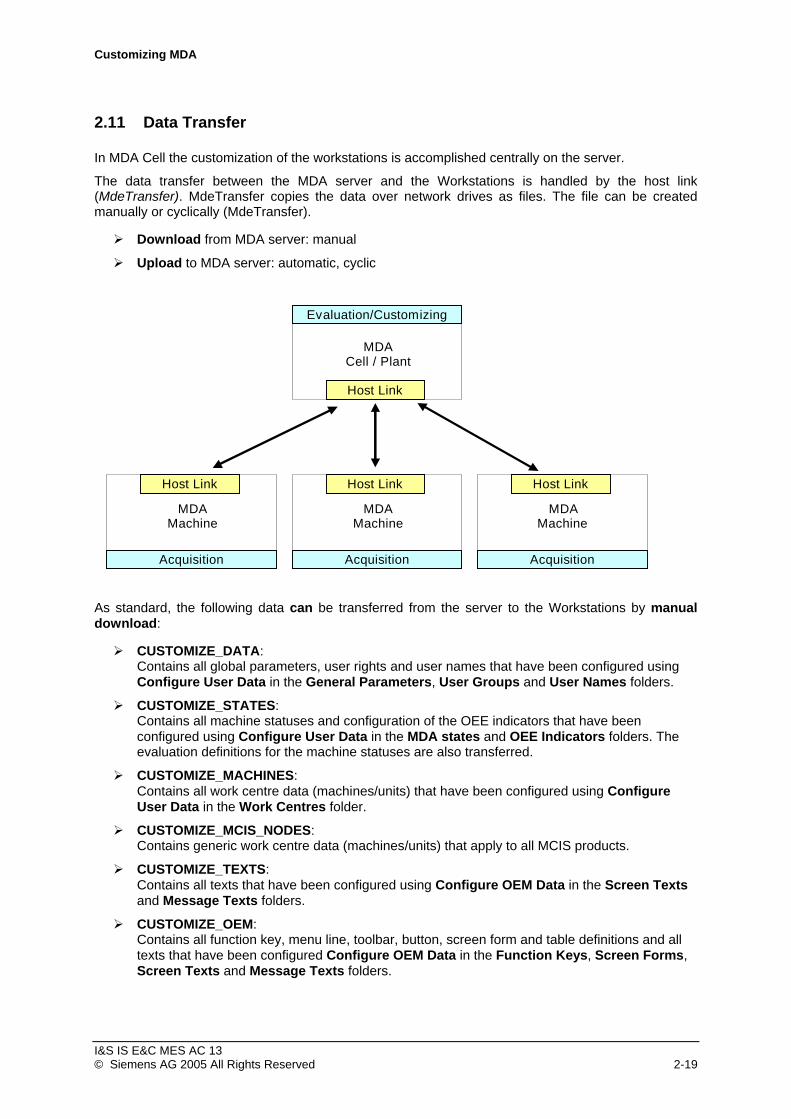
2.11 Data Transfer
In MDA Cell the customization of the workstations is accomplished centrally on the server.
The data transfer between the MDA server and the Workstations is handled by the host link (MdeTransfer). MdeTransfer copies the data over network drives as files. The file can be created manually or cyclically (MdeTransfer).
Download from MDA server: manual
Upload to MDA server: automatic, cyclic
Evaluation/Customizing
MDA Cell / Plant
Host Link
Acquisition
MDA Machine
Host Link
Acquisition
MDA Machine
Host Link
Acquisition
MDA Machine
Host Link
As standard, the following data can be transferred from the server to the Workstations by manual download:
CUSTOMIZE_DATA: Contains all global parameters, user rights and user names that have been configured using Configure User Data in the General Parameters, User Groups and User Names folders.
CUSTOMIZE_STATES: Contains all machine statuses and configuration of the OEE indicators that have been configured using Configure User Data in the MDA states and OEE Indicators folders. The evaluation definitions for the machine statuses are also transferred.
CUSTOMIZE_MACHINES: Contains all work centre data (machines/units) that have been configured using Configure User Data in the Work Centres folder.
CUSTOMIZE_MCIS_NODES: Contains generic work centre data (machines/units) that apply to all MCIS products.
CUSTOMIZE_TEXTS: Contains all texts that have been configured using Configure OEM Data in the Screen Texts and Message Texts folders.
CUSTOMIZE_OEM: Contains all function key, menu line, toolbar, button, screen form and table definitions and all texts that have been configured Configure OEM Data in the Function Keys, Screen Forms, Screen Texts and Message Texts folders.
I&S IS E&C MES AC 13 © Siemens AG 2005 All Rights Reserved 2-19
Customizing MDA
CUSTOMIZE_TRANSFER: Contains all configuration data for the host link that has been configured using Configure User Data (see chapter “) in the Data Synchronization folder. 2 “Customizing
CUSTOMIZE_INIT: Contains all configuration data which depend on the configuaration variant. If the configuaration variant of the workstation shall be changed (e. g. from MDA_WSI_OP12 to MDA_WSI_OP015), this order must be performed.
CALENDAR_DATA: Contains all works calendar data (shift and day types, working time models, calendar).
PARTS_DATA: Contains the part types to be manufactured and that have been produced on the MDA server using the Part Type Evaluations user interface.
ALARM_TEXTS: Contains all alarm texts which are used at the Workstation.
As standard the following data is transferred from the Workstations to the MDA server by means of automatic, cyclic uploading:
SYSTEM_LOGBOOK: All system logbook messages that have been generated on the Workstations.
As standard the following data is transferred from the Workstations to the MDA server by means of manual uploading:
ALARM_TEXTS: All alarm texts generated on the Workstation (currently MMC only) during MDA commissioning.
As standard, the following data is transferred immediately from the Workstations to the MDA server by MdeReport/TcpIpAdapter:
MDE_LOGBUCH (actual MDA statuses, machine counters, part type counters)
ALARM_LOGBUCH (Current alarms)
I&S IS E&C MES AC 13 © Siemens AG 2005 All Rights Reserved 2-20

Customizing MDA
2.11.1 Customizing Data Transfer
Enter the name of all workstations assigned to the MDA server using Configure User Data in the Data Synchronization > PC Names folder. The Windows network identification can be removed from the computer name (called up using Windows Start menu > Settings > System Controller > Network > Identification). All other computer names must be deleted. It must be noted that all computer names must be written in capitals. As well as the computer name, the relevant configuration variant must also be entered for all workstations. Entering the configuration variant is required for the manual download from the MDA server to the Workstations.
2.11.2 Downloading Configuration Data
With MDA Workstation running, the configurations created on the MDA server can be transferred to the Workstations as follows using the Configure User Data program (Start > Program Files > MCIS MDA > Customizing(User)):
In Configure User Data, activate menu item File > Start Data Transfer.
Select a transfer in the Transfer Number combo box.
Select a Workstation in the Computer Name combo box. For a download to all Workstations select “* -All PCs“.
Click on OK to start the download, or Cancel in order to exit the dialog without downloading.
Notes:
The download is asynchronous. At present there is no direct feedback to the MDA server, as to whether the operation has been performed. On the Workstations the download job is entered in the system logbook after it has been performed.
The downloaded parameters are not taken over by Workstation until a restart has taken place. Exception: Works calendar data (CALENDAR_DATA) and part types (PARTS_DATA) are taken over by the Workstation without a restart.
The works calendar data download (CALENDAR_DATA) usually takes place directly using the Works Calendar program (Start > Program Files > MDA > Works Calendar). On the MDA server MDA must also be running.
The configuration data for the host link (CUSTOMIZE_TRANSFER) has to downloaded first!
I&S IS E&C MES AC 13 © Siemens AG 2005 All Rights Reserved 2-21

Customizing MDA
2.11.3 Overview Transfer Orders
Download Orders:
Transfer order Tables Type Meaning/Comment
CUSTOMIZE_DATA (960) GLOBAL_PARA USER_LOGIN USER_SQL USER_GROUP MA_GROUP
V V V
General Parameters User Names unused User Groups Machine Groups
CUSTOMIZE_STATES (970) STATUS_COLOR MDEZUSTAENDE STATUS_SELECT MDE_LOGICS OEECUSTOM OEEFORMULA BDEZUSTAENDE BDE_LOGICS BDE_ACTIVITIES AUS_GRUENDE
V MDA status colours MDA status definition MDA status evaluation def. MDA logics OEE indicators OEE indicators PDA status definition PDA logics PDA logics Scrap reasons
CUSTOMIZE_MACHINES (968) APLZ_STAMM Work centres
CUSTOMIZE_MCIS_NODES (969) NODETABLE Generic MCIS data of work centres
CUSTOMIZE_TEXTS (958) TEXT_MASKS TEXT_MESSAGES
Screen form texts Screen form and message texts
CUSTOMIZE_OEM (940) BUTTON_KEYS BUTTON_PROJ BUTTON_FUNCTIONS MASK_GLOBAL MASK_FIELDS TABLE_FIELDS MENU MASK_RT SEQ_FIELDS MASK_CHECKS TEXT_MASKS TEXT_MESSAGES COLUMN_DEFINITION COLUMN_VIEW FREE_FILTER VIEW_FILTER VIEW_SORT VIEW_TYPE
V V V V V V V V
Function key codes Toolbars and buttons Function definition internal unused Screen forms Tables Menu lines Customizing PDA masks Customizing PDA masks Mask input checks Screen form texts Screen form and message texts Customizing flexible views Customizing flexible views Customizing flexible views Customizing flexible views Customizing flexible views Customizing flexible views
CUSTOMIZE_TRANSFER (950) TRANS_HEADER TRANS_TABLES TRANS_DATA TRANS_SQL TRANS_STATIONS_PARAMTRANS_STATIONS
VO VO VO VO VO VO
Header information Tables Table columns SQL statements Target computers Computer names
I&S IS E&C MES AC 13 © Siemens AG 2005 All Rights Reserved 2-22

Customizing MDA
CUSTOMIZE_INIT (999) BUTTON_KEYS BUTTON_PROJ MASK_GLOBAL MASK_FIELDS MENU TABLE_FIELDS SEQ_FIELDS MASK_CHECKS GLOBAL_PARA LANGUAGES STATUS_COLOR
V V V V V V V V V V V
Function key codes Toolbars and buttons unused Screen forms Menu lines Tables Customizing PDA masks Mask input checks General Parameters Languages MDA status colours
TRANS_HEADER TRANS_TABLES TRANS_DATA TRANS_SQL TRANS_STATIONS_PARAMTRANS_STATIONS TRANS_SAP
V V V V V V V
Header information Tables Table columns SQL statements Target computers Computer names SAP connection
CALENDAR_DATA (980) WKAL_SCH WKL_TPL WKAL_AZ_SCH WKAL_AZ_TTYP WKAL_AZ_VAR WKAL_SCH_KOM WKAL_TT_KOM
O O O O O O O
Works calendar Works calendar Works calendar Works calendar Works calendar Works calendar Works calendar
PARTS_DATA (989) PARTS_DATA O Part types
ALARM_TEXT_DATA (979) AL_TEXT Alarm texts
V = depends on configuration variant
O = Data transferred to workstation without MDA restart
Upload Orders:
Transfer Order Tables Type Meaning/Comment
ALARM_TEXTS (919) AL_TEXT Alarm texts
SYSTEM_LOGBOOK (921) ErrorMessageData A System messages
UPLOAD_STATES (800) MDEZUSTAENDE STATUS_COLOR
V
MDA status definitions MDA status colors
V = depends on configuration variant
A = automatically transfered
I&S IS E&C MES AC 13 © Siemens AG 2005 All Rights Reserved 2-23

Customizing MDA
In MDA Cell and Plant only the logbook of system messages is transferred automatically to the server.
2.12 Configuration variants
The MDA configuration is stored in a database. In principle, several configuration variants can be stored in such a database, whereby one variant is always the active configuration. Among other things the standard scope of delivery contains the following configuration:
MDA_WSM_STDPC Workstation Standard-PC
MDA_WSM_MMC Workstation MMC with OP031/OP032
MDA_WSM _OP10 Workstation MMC with OP010
MDA_WSM _OP12 Workstation MMC with OP012
MDA_WSM _OP15 Workstation MMC with OP015
The MDA Server variant contains all the configuration variants, so that a download of the respective variant can be triggered via central customizing.
The following download orders are (partially) configuration dependent:
CUSTOMIZE_INIT
CUSTOMIZE_DATA
CUSTOMIZE_OEM
CUSTOMIZE_STATES
CUSTOMIZE_TRANSFER
I&S IS E&C MES AC 13 © Siemens AG 2005 All Rights Reserved 2-24
Customizing MDA
2.13 Integration of Reports into the MDA environment
(only project specific for MDA Plant) The MDA reports need Microsoft ACCESS / Office 2000. If this package has not been installed on the MDA computer the runtime version of Microsoft ACCESS / Office 2000 can be installed from the installation CD. The runtime version is sufficient for the execution of Reports. For modifying and creat-ing new Reports the full version is necessary.
During installation the following has to be kept in mind:
• Path names must not contain blanks. • A standard printer must be installed. Only then it is possible to execute Reports. • The path to MSAccess.exe must be entered into the environment variable “Path”. • The MDA folder <MDADIR> must be set as default working folder for Microsoft ACCESS. For
this you can execute the script access_db_path.reg in the folder <MDADIR>. • The Report database must establish a connection to the existing MDA datbase. This requires
an established ODBC connection to the MDA database (normally OSFDB-ODBC). For this you can execute the script ReportConnectDB.bat in the folder <MDADIR>.
The setup installs a database OSFDB_Report.mdb in the folder <MDADIR> with two sample reports:
OEE Report
Machine counters The sample reports need a special database configuration. Only those machines are taken into con-sideration that have the value “001” in column VGW02 (for the report Machine Counters) and the value “001“ in the column VGW03 (for the OEE Report) in the table APLZ_STAMM.
Further project specific reports must be included in the database OSFDB_Report.mdb in the folder <MDADIR>. Additonally the entries PAR_NAME=’REPORT_NAME_<n>’ in the table GLOBAL_PARA, Section=’GUI_RT’ of the configuration database must be adapted.
The switching to a foreign language is accomplished by editing the Report. The module “Frem-dsprache“ must be replaced by the respective module “Fremdsprache_<Sprache>”. Non-existing lan-guages must be created analogously.
Using configuration of user data (Start > Program Files > MCIS MDA > Customizing (User)) the following parameters can be adapted choosing the node General parameters > GUI_RT:
• REPORT_ACCESSPATH Program MSAccess.exe (possibly including the path if it is identical on
all MDA HMI workstation). • REPORT_DATABASE Report database (possibly including the path if it is identical on
all MDA HMI workstation and if the MDA folder is not the default working folder of Microsoft ACCESS).
I&S IS E&C MES AC 13 © Siemens AG 2005 All Rights Reserved 2-25


Customizing MDA
3 Interfaces
There are several types of automatic MDA data acquisition (machine statuses/counters) and PDA data (part type counter/part type cycle times):
PnP interface (SINUMERIK) (machine statuses only)
PLC interface machine (SINUMERIK)
PLC interface Multiple Machines (SINUMERIK)
OPC interface (ProTool/Pro)
Test interface
In the SINUMERIK PnP Interface (Plug&Play) variant, data that is available on the MMC as standard is used to determine the current machine status. In the PnP variant only the status of an NC channel can be acquired – there are no units.
In the other variants, defined data blocks that are in one or more data blocks are read from the PLC by the MDA coupling module and evaluated. The first data block (MDC Cluster) contains the MDA data (machine statuses, machine counters). The other data block (PDC Cluster) contains the PDA data (part type counters and cycle times). These data blocks must be provided with appropriate data by the PLC program.
In the SINUMERIK PLC Interface Machine variant, the machine statuses of one can be acquired via the MDC cluster. Up to 128 statuses and the machine counters can be acquired in an MDC cluster. The PDA data can be acquired via the PDC cluster.
In the SINUMERIK PLC Interface Multiple Machines variant, the machine statuses for up to 8 machines can be acquired via 8 MDC clusters. Up to 128 statuses and the machine counters can be acquired in an MDC cluster. The PDA data can be acquired via the PDC cluster. MDC clusters and PDC are in one data block each and both data blocks are in the same PLC. This PLC has to be on the standard NCU.
In the OPC ProTool/Pro Interface variant, the machine statuses for a machine or unit can be acquired via the MDC cluster. Up to 128 statuses and the machine counters can be acquired in an MDC cluster. The PDA data can be acquired via the PDC cluster.
Other OPC interfaces like WinCC, WinAC or SIMATIC NET can be asked for within projects.
The test interface makes it possible to enter MDA and PDA data via a simulated PLC interface (see chap. 5.8 “Test Program TestSrv.exe”).
I&S IS E&C MES AC 13 © Siemens AG 2005 All Rights Reserved 3-1
Customizing MDA
3.1 Cluster Data Structures
The cluster data structures are described below. The <Unsigned Int32> and <Float> data types mentioned in the cluster description are referred to as <DWORD> and <REAL> in the S7 documentation. DW means data word (two bytes).
3.1.1 Structure of MDC Cluster
In previous descriptions this cluster was referred to Structure DB13 compact.
This cluster can be used for the following variants:
PLC interface machine (SINUMERIK)
PLC interface Multiple Machines (SINUMERIK)
OPC interface (ProTool/Pro)
Test interface
The AWL file for setting up the cluster on the PLC is on the MDA medium (\doc\MDC.awl). That applies to the multiple machines interface too (\doc\MDC8.awl).
The MDC cluster contains the MDA data for a machine/unit. Up to 8 MDC clusters for MDA can be defined for Multiple Machines and ProTool/Pro, i.e. data for a maximum of 8 machines/units can be acquired.
At present, MDA evaluates the first three counters (good, waste and rework) in the MDC cluster and the 128-bit machine status array. Acquisition of the other part/cycle counters and the analog values is planned for future versions.
I&S IS E&C MES AC 13 © Siemens AG 2005 All Rights Reserved 3-2

Customizing MDA
DB Name Description Data Type #Byte
00 Coordination value Spare Unsigned Int32 4
04 Unit status 1 = Setup, processing, fault, 128 Bit-Array 16 Machine status maintenance, ...
20 Counter 1 Good (absolute) Unsigned Int32 4
24 Counter 2 Waste (absolute) Unsigned Int32 4
28 Counter 3 Rework (absolute) Unsigned Int32 4
32 Counter 4 Spare Unsigned Int32 4
36 Counter 5 Spare Unsigned Int32 4
40 Counter 6 Spare Unsigned Int32 4
44 Cycle counter 1 Spare Unsigned Int32 4
48 Cycle counter 2 Spare Unsigned Int32 4
52 Cycle counter 3 Spare Unsigned Int32 4
56 Cycle counter 4 Spare Unsigned Int32 4
60 Shift start Spare Unsigned Int32 4
64 Shift number Spare Unsigned Int32 4
68 Analog value 1 Spare Unsigned Int32 4
72 Analog value 2 Spare Unsigned Int32 4
76 Analog value 3 Spare Unsigned Int32 4
80 Analog value 4 Spare Unsigned Int32 4
Only the highlighted lines are currently evaluated by MDA. All the others are spare for future versions.
I&S IS E&C MES AC 13 © Siemens AG 2005 All Rights Reserved 3-3

Customizing MDA
In MDA the individual bits in the 128-bit bit pattern for a unit are sequentially numbered. The first bit is given the symbolic name of Bit_1 and the last bit has the symbolic name of Bit_128. Addressing in the PLC program normally takes place using bytes and bits, whereby the first bit of a byte is bit 7 and the last byte is bit 0. This must be taken into consideration when customizing. The following table shows the assignment between the symbolic name in MDA and the PLC addresses for the bits:
Symbolic PLC address Name Unit 1
Bit_1 DBX 4.7
Bit_2 DBX 4.6
Bit_3 DBX 4.5
Bit_4 DBX 4.4
Bit_5 DBX 4.3
Bit_6 DBX 4.2
Bit_7 DBX 4.1
Bit_8 DBX 4.0
Bit_9 DBX 5.7
Bit_10 DBX 5.6
Bit_11 DBX 5.5
Bit_12 DBX 5.4
Bit_13 DBX 5.3
Bit_14 DBX 5.2
Bit_15 DBX 5.1
... ...
Bit_127 DBX 19.1
Bit_128 DBX 19.0
I&S IS E&C MES AC 13 © Siemens AG 2005 All Rights Reserved 3-4
Customizing MDA
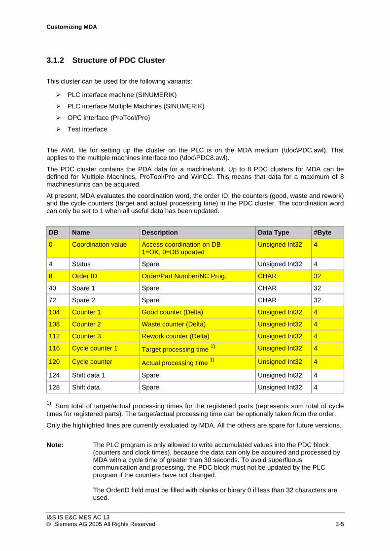
3.1.2 Structure of PDC Cluster
This cluster can be used for the following variants:
PLC interface machine (SINUMERIK)
PLC interface Multiple Machines (SINUMERIK)
OPC interface (ProTool/Pro)
Test interface
The AWL file for setting up the cluster on the PLC is on the MDA medium (\doc\PDC.awl). That applies to the multiple machines interface too (\doc\PDC8.awl).
The PDC cluster contains the PDA data for a machine/unit. Up to 8 PDC clusters for MDA can be defined for Multiple Machines, ProTool/Pro and WinCC. This means that data for a maximum of 8 machines/units can be acquired.
At present, MDA evaluates the coordination word, the order ID, the counters (good, waste and rework) and the cycle counters (target and actual processing time) in the PDC cluster. The coordination word can only be set to 1 when all useful data has been updated.
DB Name Description Data Type #Byte
0 Coordination value Access coordination on DB Unsigned Int32 4 1=OK, 0=DB updated
4 Status Spare Unsigned Int32 4
8 Order ID Order/Part Number/NC Prog. CHAR 32
40 Spare 1 Spare CHAR 32
72 Spare 2 Spare CHAR 32
104 Counter 1 Good counter (Delta) Unsigned Int32 4
108 Counter 2 Waste counter (Delta) Unsigned Int32 4
112 Counter 3 Rework counter (Delta) Unsigned Int32 4 1)116 Cycle counter 1 Unsigned Int32 4 Target processing time 1)120 Cycle counter Unsigned Int32 4 Actual processing time
124 Shift data 1 Spare Unsigned Int32 4
128 Shift data Spare Unsigned Int32 4 1) Sum total of target/actual processing times for the registered parts (represents sum total of cycle times for registered parts). The target/actual processing time can be optionally taken from the order.
Only the highlighted lines are currently evaluated by MDA. All the others are spare for future versions.
Note: The PLC program is only allowed to write accumulated values into the PDC block (counters and clock times), because the data can only be acquired and processed by MDA with a cycle time of greater than 30 seconds. To avoid superfluous communication and processing, the PDC block must not be updated by the PLC program if the counters have not changed. The OrderID field must be filled with blanks or binary 0 if less than 32 characters are used.
I&S IS E&C MES AC 13 © Siemens AG 2005 All Rights Reserved 3-5

Customizing MDA
3.2 PnP Interface (SINUMERIK)
The General Parameters > PIT > PIT.PROFILE parameter in Configure User Data (Start > Program Files >MDA > Customizing (User)) must be set to the value “Pit_NCDDE_PNP.ini“ to activate the interface.
The NCU name must be correctly configured for WinDBE in order to allow MDA to communicate with the MMC (Ncdde server). It must also be defined for which channel the data is to be acquired. By default, the coupling module is configured for NCU name machineswitch and channel 1. If acquisition is to take place for another NCU name or another channel, the interface must be adapted.
The following parameters must be adapted using Configure User Data in folder General Parameters -> PIT:
The Machine1.Property1.Address parameter must be set to “ncdde|machineswitch|/Bag/State/opMode[u1]“.
The Machine1.Property2.Address parameter must be set to “ncdde|machineswitch|/Channel/State/chanAlarm[u1]“.
The Machine1.Property3.Address parameter must be set to “ncdde|machineswitch|/Channel/State/progStatus[u1]“.
The Machine1.Property4.Address parameter must be set to ”mbdde|alarme|NrOfAlarm“.
In the above cases, machineswitch is the NCU name, u1 is channel 1, u2 is channel 2 etc.
The machine configured in the database (e.g. W001, MACH1110, 001) is to be assigned to status group 2000, for example. The required MDA statuses for this status group have already been configured. Assignment to the status group takes place when the machine/units are customized.
The following diagram the status data of the channel and operating type group (BAG) is accessed using the configured channel number:
Customizing
Channel
♦ chanAssignment♦ chanAlarm♦ progStatus
BAG
♦ opMode
The following DDE variables in the NCDDE server and the alarm server are accessed on the MMC, whereby the default value of “machineswitch “ is used as the DDE topic.
Assignment of channel to mode group (BAG):
Application/Topic=/ncdde/machineswitch
Item=/Nck/Configuration/chanAssignment[<Channel number>] 0 = Channel not present n = Channel assigned to BAG n
I&S IS E&C MES AC 13 © Siemens AG 2005 All Rights Reserved 3-6
Customizing MDA
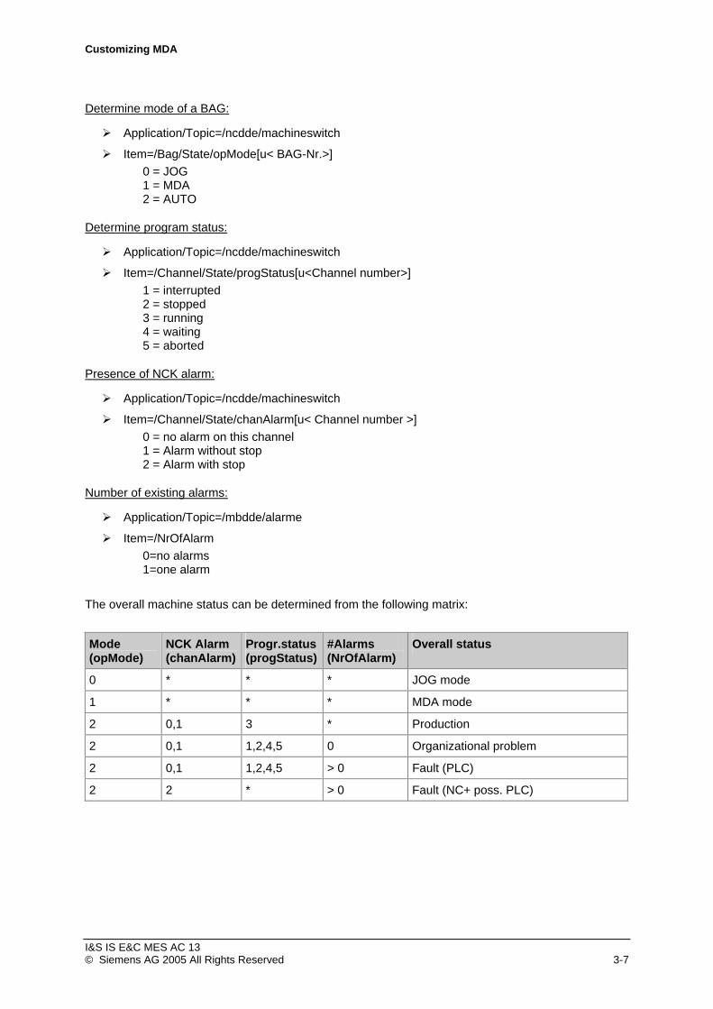
Determine mode of a BAG:
Application/Topic=/ncdde/machineswitch
Item=/Bag/State/opMode[u< BAG-Nr.>] 0 = JOG 1 = MDA 2 = AUTO
Determine program status:
Application/Topic=/ncdde/machineswitch
Item=/Channel/State/progStatus[u<Channel number>] 1 = interrupted 2 = stopped 3 = running 4 = waiting 5 = aborted
Presence of NCK alarm:
Application/Topic=/ncdde/machineswitch
Item=/Channel/State/chanAlarm[u< Channel number >] 0 = no alarm on this channel 1 = Alarm without stop 2 = Alarm with stop
Number of existing alarms:
Application/Topic=/mbdde/alarme
Item=/NrOfAlarm 0=no alarms 1=one alarm
The overall machine status can be determined from the following matrix:
Mode NCK Alarm Progr.status #Alarms Overall status (opMode) (chanAlarm) (progStatus) (NrOfAlarm)
0 * * * JOG mode
1 * * * MDA mode
2 0,1 3 * Production
2 0,1 1,2,4,5 0 Organizational problem
2 0,1 1,2,4,5 > 0 Fault (PLC)
2 2 * > 0 Fault (NC+ poss. PLC)
I&S IS E&C MES AC 13 © Siemens AG 2005 All Rights Reserved 3-7

Customizing MDA
3.3 PLC Interface Machine (SINUMERIK)
In order to activate the interface the General Parameters > PIT > PIT.PROFILE parameter has to be set to “Pit_NCDDE_PLC_MACH.ini“ in Configure User Data (Start > Program Files >MDA > Customizing (User)).
The automatic acquisition of MDA data via the PLC interface relies on having a prefabricated interface (MDC cluster) to the PLC. The interface has Plug&Play capability, but requires programming effort in the PLC to supply the MDC cluster with MDA data.
The automatic acquisition of PDA data via the PLC interface also relies on having a prefabricated interface (PDC cluster) to the PLC. The interface has Plug&Play capability, but requires programming effort in the PLC to supply the PDC cluster with PDA data.
The MDC and PDC clusters are in two different PLC data blocks. For special projects it is possible to put them into the same PLC data block (see description of PDC-Cluster). The structure of the MDC and PDC cluster is described in the chapter 3.1 “Cluster Data Structures“. The counters (good, waste and rework) and the machine statuses are evaluated in the MDC cluster. The PDA data are evaluated in the PDC cluster.
MDC-Cluster
Customizing
The position of the MDC cluster in the data block has to be defined using Pit_NCDDE_PLC_MACH.ini initialisation file. The following parameters have to be adapted:
The ITEM1 parameter in NCDDE_PLC.CLUSTER1 section must be set to: ncdde|machineswitch|/Plc/Datablock/Byte[c13,>0,#84]("!xl%02lx")
In this case c13 stands for data block 13, and 0 is the start byte address of the cluster in the data block. The length of the MDC structure is 84 Bytes.
The NCU name must be correctly configured for MDA so that MDA can communicate with the MMC (Ncdde server). The coupling module is configured for NCU name machineswitch by default. The name has to be adapted in the following parameters for another NCU name:
In parameter ITEM1 in NCDDE_PLC.CLUSTER1 section the bold part of the value: ncdde|machineswitch|/Plc/Datablock/Byte[c13,>0,#84]("!xl%02lx")
Notice: The assignment of a status field (128-bit array) to a machine or unit takes place when customizing the machines/units (see chapter 2.3 “Customizing Machines/Units“) using the Cluster and Position (always “1“) parameters.
Examples:
Cluster: 1, Position: 1 represents first machine
Notice: The Type of automatic acquisition parameter must also be used to define whether MDA or PDA data is being acquired when customizing the machines/units.
I&S IS E&C MES AC 13 © Siemens AG 2005 All Rights Reserved 3-8

Customizing MDA
MDC_OUT-Cluster
Customizing
The position of the MDC OUT cluster in the data block has to be defined Pit_NCDDE_PLC_MACH.ini initialisation file. The following parameters have to be adapted:
The ITEM1 parameter in NCDDE_PLC.CLUSTER2 section must be set to: ncdde|machineswitch|/Plc/Datablock/Byte[c13,>84,#84]("!xl%02lx")
In this case c13 stands for data block 13, and 84 is the start byte address of the cluster in the data block. The length of the MDC structure is 84 Bytes.
The NCU name must be correctly configured for MDA so that MDA can communicate with the MMC (Ncdde server). The coupling module is configured for NCU name machineswitch by default. The name has to be adapted in the following parameters for another NCU name (see chapter 2.3 “Customizing Machines/Units“):
In parameter ITEM1 in NCDDE_PLC.CLUSTER2 section the bold part of the value: ncdde|machineswitch|/Plc/Datablock/Byte[c13,>84,#84]("!xl%02lx")
I&S IS E&C MES AC 13 © Siemens AG 2005 All Rights Reserved 3-9

Customizing MDA
PDC Cluster
Customizing
The position of the PDC cluster in the data block has to be defined using Pit_NCDDE_PLC_MACH.ini initialisation file. The following parameters have to be adapted:
The ITEM1 parameter in NCDDE_PLC.CLUSTER3 section must be set to: ncdde|machineswitch|/Plc/Datablock/Byte[c14,>0,#132]("!xl%02lx")
The FLAG parameter in NCDDE_PLC.CLUSTER3 section must be set to: ncdde|machineswitch|/Plc/Datablock/Byte[c14,>0,#4]("!xl%02lx")
In this case c14 stands for data block 14, and 0 is the start byte address of the cluster in the data block. The coordination flag (FLAG in NCDDE_PLC.CLUSTER2 section) is in the first four bytes of the PDC cluster. Both start byte addresses must therefore always be identical!
If the PDC cluster should be in the same data block 13 like the MDC cluster the configuration has to be like this:
The ITEM1 parameter in NCDDE_PLC.CLUSTER3 section must be set to: ncdde|machineswitch|/Plc/Datablock/Byte[c13,>168,#132]("!xl%02lx")
The FLAG parameter in NCDDE_PLC.CLUSTER3 section must be set to: ncdde|machineswitch|/Plc/Datablock/Byte[c13,>168,#4]("!xl%02lx")
The NCU name must be correctly configured for MDA so that MDA can communicate with the MMC (Ncdde server). The coupling module is configured for NCU name machineswitch by default. The name has to be adapted in the following parameters for another NCU name (see chapter 2.3 “Customizing Machines/Units“):
In parameter ITEM1 in NCDDE_PLC.CLUSTER2 section the bold part of: ncdde|machineswitch|/Plc/Datablock/Byte[c14,>0,#132]("!xl%02lx")
In parameter FLAG in NCDDE_PLC.CLUSTER2 section the bold part of ncdde|machineswitch|/Plc/Datablock/Byte[c14,>0,#4]("!xl%02lx")
Notice: The assignment to a machine or unit takes place when customizing the machines/units (see chapter 2.3 “Customizing Machines/Units“) using the Cluster (always “1“) and Position parameters (always “1”). The Type of automatic acquisition parameter must also be used to define whether MDA or PDA data is being acquired when customizing the machines/units.
I&S IS E&C MES AC 13 © Siemens AG 2005 All Rights Reserved 3-10

Customizing MDA
3.4 PLC Interface Multiple Machines (SINUMERIK)
In order to activate the interface the General Parameters > PIT > PIT.PROFILE parameter has to be set to “Pit_NCDDE_PLC_MACH8.ini“ in Configure User Data (Start > Program Files > MCIS MDA >Customizing (User)).
The automatic acquisition of MDA data via the PLC interface relies on having a prefabricated interface (MDC cluster) to the PLC. The interface has Plug&Play capability, but requires programming effort in the PLC to supply the MDC cluster with MDA data.
The automatic acquisition of PDA data via the PLC interface also relies on having a prefabricated interface (PDC cluster) to the PLC. The interface has Plug&Play capability, but requires programming effort in the PLC to supply the PDC cluster with PDA data.
All MDC are in one PLC data block and all PDC clusters in an other one. The structure of the MDC and PDC cluster is described in the chapter 3.1 “Cluster Data Structures“. The counters (good, waste and rework) and the machine statuses are evaluated in the MDC cluster. The PDA data are evaluated in the PDC cluster.
By default data block DB13 for MDC cluster, datablock DB14 for PDC cluster and for communication with the MMC the NCU name machineswitch is used. Changes of this customizing have to be done in the configuration file Pit_NCDDE_PLC_MACH8.ini. In this case c13 stands for data block 13.
MDC-Cluster
Customizing
The position of the MDC cluster in the data block has to be defined in Pit_NCDDE_PLC_MACH8.ini initialisation file. The following parameters have to be adapted:
The ITEM1 parameter in NCDDE_PLC.CLUSTER1 section must be set to: ncdde|machineswitch|/Plc/Datablock/Byte[c13,>0,#672]("!xl%02lx")
The SIZE1 parameter in in NCDDE_PLC.CLUSTER1 section must be set to: 672
In this case c13 stands for data block 13, and 0 is the start byte address of the first cluster in the data block. The length of the MDC structure is 8 * 84 = 672 Bytes.
If there are less than 8 machines, the read length can be optimized. For that change the length of 672 to the necessary length n * 84 with n = number of machines.
The NCU name must be correctly configured for MDA so that MDA can communicate with the MMC (Ncdde server). The coupling module is configured for NCU name machineswitch by default. The name has to be adapted in the following parameters for another NCU name (see chapter 2.3 “Customizing Machines/Units“):
In parameter ITEM1 of NCDDE_PLC.CLUSTER1 section the bold part of the value: ncdde|machineswitch|/Plc/Datablock/Byte[c13,>0,#672]("!xl%02lx")
I&S IS E&C MES AC 13 © Siemens AG 2005 All Rights Reserved 3-11

Customizing MDA
Notice: The assignment of a status field (128-bit array) to a machine or unit takes place when customizing the machines/units using the Cluster and Position (always “1“) parameters.
Examples:
Cluster: 1, Position: 1 represents first machine
Cluster: 2, Position: 1 represents second machine
Notice: The Type of automatic acquisition parameter must be used to define whether MDA or PDA data is being acquired when customizing the machines/units (Configure User Data).
MDC_OUT-Cluster
Customizing
The position of the MDC OUT cluster in the data block has to be defined Pit_NCDDE_PLC_MACH8.ini initialisation file. The following parameters have to be adapted:
The ITEM1 parameter in NCDDE_PLC.CLUSTER2 section must be set to: ncdde|machineswitch|/Plc/Datablock/Byte[c13,>672,#84]("!xl%02lx")
In this case c13 stands for data block 13, and 672 is the start byte address of the cluster in the data block. The length of the MDC structure is 84 Bytes.
The NCU name must be correctly configured for MDA so that MDA can communicate with the MMC (Ncdde server). The coupling module is configured for NCU name machineswitch by default. The name has to be adapted in the following parameters for another NCU name (see chapter 2.3 “Customizing Machines/Units“):
In parameter ITEM1 in NCDDE_PLC.CLUSTER2 section the bold part of the value: ncdde|machineswitch|/Plc/Datablock/Byte[c13,>672,#84]("!xl%02lx")
For further machines you have to adapt the following sections: NCDDE_PLC.CLUSTER3 for machine 2, NCDDE_PLC.CLUSTER4 for machine 3, … NCDDE_PLC.CLUSTER8 for machine 7, NCDDE_PLC.CLUSTER9 for machine 8.
I&S IS E&C MES AC 13 © Siemens AG 2005 All Rights Reserved 3-12

Customizing MDA
PDC Cluster
Customizing
The position of the PDC cluster in the data block has to be defined using Pit_NCDDE_PLC_MACH8.ini initialisation file. The following parameters have to be adapted:
The ITEM1 parameter of NCDDE_PLC.CLUSTER10 section must be set to: ncdde|machineswitch|/Plc/Datablock/Byte[c14,>0,#132]("!xl%02lx")
The FLAG parameter of NCDDE_PLC.CLUSTER10 section must be set to: ncdde|machineswitch|/Plc/Datablock/Byte[c14,>0,#4]("!xl%02lx")
In this case c14 stands for data block 14, and 0 is the start byte address of the cluster in the data block. The coordination flag (FLAG parameter of NCDDE_PLC.CLUSTER10 section) is in the first four bytes of the PDC cluster. Both start byte addresses must therefore always be identical!
The NCU name must be correctly configured for MDA so that MDA can communicate with the MMC (Ncdde server). The coupling module is configured for NCU name machineswitch by default. The name has to be adapted in the following parameters for another NCU name (see chapter 2.3 “Customizing Machines/Units“):
In parameter ITEM1 of NCDDE_PLC.CLUSTER10 section the bold part of: ncdde|machineswitch|/Plc/Datablock/Byte[c14,>0,#132]("!xl%02lx")
In parameter FLAG of NCDDE_PLC.CLUSTER10 section the bold part of ncdde|machineswitch|/Plc/Datablock/Byte[c14,>0,#4]("!xl%02lx")
For further machines you have to adapt the following sections: NCDDE_PLC.CLUSTER11 for machine 2, NCDDE_PLC.CLUSTER12 for machine 3, … NCDDE_PLC.CLUSTER16 for machine 7, NCDDE_PLC.CLUSTER17 for machine 8.
I&S IS E&C MES AC 13 © Siemens AG 2005 All Rights Reserved 3-13

Customizing MDA
3.5 OPC Interface (ProTool/Pro)
In order to activate the interface the General Parameters > PIT > PIT.PROFILE parameter has to be set to “Pit_ProTool.ini “ in Configure User Data (Start > Program Files > MCIS MDA > Customizing (User)).
The automatic acquisition of MDA data via the PLC interface relies on having a prefabricated interface (MDC cluster) to the PLC. The interface has Plug&Play capability, but requires programming effort in the PLC to supply the MDC cluster with MDA data.
The automatic acquisition of PDA data via the PLC interface also relies on having a prefabricated interface (PDC cluster) to the PLC. The interface has Plug&Play capability, but requires programming effort in the PLC to supply the PDC cluster with PDA data.
The MDC and PDC clusters are always in PLC data blocks. The MCD and PCD cluster contains the MDA and PDA data for one machine/unit. Data for a maximum of 8 machines/units can be acquired using the clusters. The structure of the MMC and PDC clusters is described in the chapter 3.1 “Cluster Data Structures”.
MDC Cluster
Customizing
An MDC cluster corresponds to a variable in ProTool/Pro and contains a machine/unit. MDC clusters can be distributed over several data blocks. The data blocks may be on different controllers. The length of a data block is therefore variable (n * 84 bytes).
A variable of type Byte must be created in ProTool/Pro CS for each MDC cluster:
Name: Value = “MDA_M1, MDA_M2, ...“
Acquisition cycle (s): Value = “2“
Number of elements: Value = “84“
Range: Value = “DB“
DB: Value = “13“ (possibly 14, 15, ...)
DBB: Value = “(n-1) * 84“
Notice: “OPC Server” must also be selected in ProTool/Pro in menu item Target System > Settings.
The cluster is assigned to a machine or unit when customizing the machines/aggregates (see chapter 2.3 “Customizing Machines/Units“) using the Cluster and Position parameters (Work centres > Acquisition), whereby the Position parameter must always be set to “1“. Examples: • Cluster 1, Position 1 represents ProTool variables MDA_M1
• Cluster 3, Position 1 represents ProTool variables MDA_M3
I&S IS E&C MES AC 13 © Siemens AG 2005 All Rights Reserved 3-14

Customizing MDA
The Type of automatic acquisition parameter must also be used when customizing the machines/unit in order to define whether MDA and/or PDA data is to be acquired.
PDC Cluster
Customizing
A PDC cluster corresponds to a variable in ProTool/Pro and contains a machine/unit. PDC clusters can be distributed over several data blocks. The data blocks may be on different controllers. The length of a data block is therefore variable (n * 132 Byte).
Two variables of type Byte must be created in ProTool/Pro CS for each PDC cluster.
Variable 1 (PDC cluster):
Name: Value = “MDA_P1, MDA_P2, ...“
Acquisition cycle (s): Value = “5“
Number of elements: Value = “132“
Range: Value = “DB“
DB: Value = “14“ (possibly 13, 15, ...)
DBB: Value = „”n-1) * 132“
Variable 2 (coordination flag in PDC cluster):
Name: Value = “MDA_PF1, MDA_PF2, ...“
Acquisition cycle (s): Value = “2“
Number of elements: Value = “4“
Range: Value = “DB“
DB: Value = “14“ (possibly 13, 15, ...)
DBB: Value = (n-1) * 132
Notice: Menu item “OPC Server“ must also be selected in Target System > Settings in ProTool/Pro. The coordination flag is contained in the first four bytes of the PDC cluster. The data block number (DB) and the start byte address (DBB) must therefore always be identical in variable pairs MDA_P1, MDA_P2, ... and MDA_PF1, MDA_PF2, ...! If MDA data is also being acquired for a machine/unit, ProTool variables MDA_M1, MDA_M2, ... in the MDC cluster must correspond with the ProTool variables for the PDC cluster MDA_P1, MDA_P2, ... and MDA_PF1, MDA_PF2, ...
I&S IS E&C MES AC 13 © Siemens AG 2005 All Rights Reserved 3-15

Customizing MDA
The cluster is assigned to a machine or unit when customizing the machines/aggregates (see chapter 2.3 “Customizing Machines/Units“) using the Cluster and Position parameters (Work centres > Acquisition), whereby the Position parameter must always be set to “1“. Examples: • Cluster 1, Position 1 represents ProTool variables MDA_P1 and MDA_PF1
• Cluster 3, Position 1 represents ProTool variables MDA_P3 and MDA_PF3
The Type of automatic acquisition parameter must also be used when customizing the machines/unit in order to define whether MDA and/or PDA data is to be acquired.
If MDA data is also being acquired for a machine/unit, ProTool variables MDA_M1, MDA_M2, ... in the MDC cluster must correspond with the ProTool variables for the PDC cluster MDA_P1, MDA_P2, ... and MDA_PF1, MDA_PF2, ...
3.6 Overview
Interface PIT.PROFILE AWL-Datei
PnP Interface (SINUMERIK) Pit_NCDDE_PNP.ini
PLC Interface Machine (SINUMERIK) Pit_NCDDE_PLC_MACH.ini MDC.awl PDC.awl
PLC Interface Multiple Machines (SINUMERIK)
Pit_NCDDE_PLC_MACH8.ini MDC8.awl PDC8.awl
OPC Interface (ProTool/Pro) Pit_ProTool.ini MDC.awl PDC.awl
MDC8.awl PDC8.awl
Test Interface Pit_NCDDE_TST.ini
I&S IS E&C MES AC 13 © Siemens AG 2005 All Rights Reserved 3-16

Customizing MDA
4 Software update / First commissioning of MDA workstations
With installation of MDA Cell all for the acquisition terminals necessary files are placed in directory <MCISDIR>\Terminals. Using the remote control program <MDADIR>\RCTerminal.exe the actual files and programs can be transfered to the workstations. 4.1 Preparatories on the MDA Server
During installation of MDA Cell following directory tree was created:
The directory <MCISDIR>\Terminals\Copy contains all the programs, configuration files and templates for the MDA Workstations.
Subdirectory Copy\MDA\global contains all the files that are to be transferred to all the terminals.
In the global directory, there are three subdirectories
• StdPC
• MMC
• PCU
which contain in each case the different variants of programs MdeGUI.exe and AlarmGUI.exe as well as templates of StartMDE.ini files.
You can create for each terminal a separate subdirectory of MDA that contains the terminal-specific files. The names of the subdirectories correspond to the workstation computer names.
I&S IS E&C MES AC 13 © Siemens AG 2005 All Rights Reserved 4-1
Customizing MDA
The shared directory called Update is the actual transfer directory.
The directory structure is similar to the Copy directory:
<MCISDIR>\Terminals \ Update \ MDA \ global
<MCISDIR>\Terminals \ Update \ MDA \ Workstation1
<MCISDIR>\Terminals \ Update \ MDA \ Workstation2
Commissioning engineers must copy the files that are to be transferred from the Copy directory to the Update directory. When doing this, they must ensure that they copy the correct variants from the global subdirectories (MMC, PCU, StdPC) to global.
The workstations first fetch the data from the global subdirectory and then from the subdirectory that has the workstation’s computer name.
Each workstation copies to the Reply directory a reply file after it has carried out the software update. The filename corresponds to the workstation’s computer name. This means that commissioning engineers can see at a central location which of the workstations have already fetched their data. The system enters the outputs of the copy job in the reply file. This means that you can check on the server whether the job was carried out successfully or not.
Dividing the directories into copy and update directories is for ensuring that in ongoing operation the system does not need to continually reload all the programs and databases. After carrying out the software update, the commissioning engineer deletes the files from the update tree.
4.2 Preparations on the Workstations
Setting the System Time Before activating MDA, you must set the correct system time (date and clock time) on the computer. If you turn back the system time at a later date, MDA does not acquire any more data until the clock reaches the old time. If you turn the system time forwards at a later date, MDA generates at the next start-up data for the entire period of time by extending the last status conditions appropriately.
Under some circumstances, the system time can be set by the time synchronization in StartMDE.ini.
I&S IS E&C MES AC 13 © Siemens AG 2005 All Rights Reserved 4-2
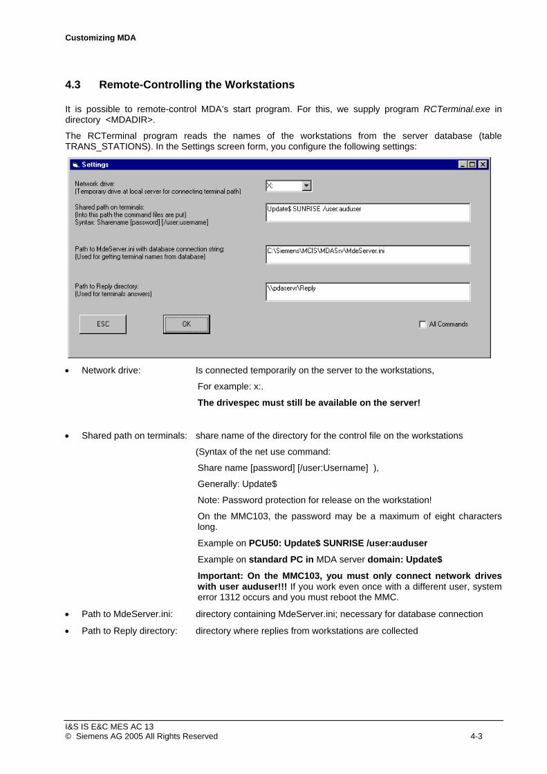
Customizing MDA
4.3 Remote-Controlling the Workstations
It is possible to remote-control MDA’s start program. For this, we supply program RCTerminal.exe in directory <MDADIR>.
The RCTerminal program reads the names of the workstations from the server database (table TRANS_STATIONS). In the Settings screen form, you configure the following settings:
• Network drive: Is connected temporarily on the server to the workstations,
For example: x:.
The drivespec must still be available on the server!
• Shared path on terminals: share name of the directory for the control file on the workstations
(Syntax of the net use command:
Share name [password] [/user:Username] ),
Generally: Update$
Note: Password protection for release on the workstation!
On the MMC103, the password may be a maximum of eight characters long.
Example on PCU50: Update$ SUNRISE /user:auduser
Example on standard PC in MDA server domain: Update$
Important: On the MMC103, you must only connect network drives with user auduser!!! If you work even once with a different user, system error 1312 occurs and you must reboot the MMC.
• Path to MdeServer.ini: directory containing MdeServer.ini; necessary for database connection
• Path to Reply directory: directory where replies from workstations are collected
I&S IS E&C MES AC 13 © Siemens AG 2005 All Rights Reserved 4-3

Customizing MDA
The current Windows user on the server must have access to the Workstation computer. Test: Connecting the drive using the Windows Explorer.
After this, you can remote control the running MDA of the selected Workstation by choosing the command and clicking on the Transfer Command pushbutton:
The commands have the following meanings:
• Restart Eval. SW Quit MDA, update software and restart it
• Update Start Program update start process of MDA
To carry out a software update, you use the „Restart Eval. SW“ command. After updating the software, the workstations send a file containing the results of the update jobs to the Reply directory. After this, the system removes the workstations from the list of Missing replies and enters them in the list of Replies.
I&S IS E&C MES AC 13 © Siemens AG 2005 All Rights Reserved 4-4

Customizing MDA
You can display the results of the update jobs by double-clicking on the associated entry in the Reply list.
With the „Restart Eval. SW“ command, you must note that the system tries to download or actually downloads files from the server's update directory before cold restarting MDA. This is exploited in further operations.
4.4 Updating the Software via the Transfer Directory
MDA's software is updated in several stages.
First of all, you verify again that the MDA server database is complete and has been customized to the project.
After this, you ensure that all the programs and project-specifically customized .ini files of MDA are in the Copy directory. In particular, ensure that the paths or drives for the workstations installation directories are entered correctly (MMC103: c:\add_on, PCU50: f:\add_on, Standard-PC: depends on installation) !
In the case of carrying out a time synchronization between server and workstation using the program StartMDE: “;SyncWindows=1“ bzw. “;SyncSinumerik=1“
in the transfer files “copy\MDA\global\*\Startmde*.ini”, section [TIME_SYNC] the semicolon (comment character) in the lines “;SyncWindows=1“ and “;SyncSinumerik=1“ must be deleted respectively .
Before the software can be distributed, MDA must be started on all the Workstations ! The MMC103s must be in Service Mode (see Chapter 4.1 “Preparatories on the MDA Server“) !
4.4.1 Transferring the project specific or new programs
The first step is to transfer the programs, configuration files, etc. to the workstations. During a commissioning only project specific programs or configuration files have to be transferred. To do this, copy contents of the Copy directory to the Update directory. Normally this step is not necessary and you can continue with the next chapter. During a software update you copy only the new files into the Update directory.
Execute “Restart Eval. SW“.
The system now downloads the files to the workstations. At the same time, all the transferred ActiveX programs and OCX files on the workstations are automatically registered.
Once the files have been transferred to all the workstations (check this on the basis of the Reply directory), delete all the files from the Update tree.
I&S IS E&C MES AC 13 © Siemens AG 2005 All Rights Reserved 4-5

Customizing MDA
4.4.2 Resolution of computer names in the network
The resolution of computer names for the TCP/IP communication (getting the IP address for a given computer name) is be done via DNS or via hosts file. As default MDA uses DNS. If there is no DNS server in the network or the connection to this server is not guaranteed in case of a instable network at the workstation you have to expand the file
%windir%\System32\drivers\etc\hosts for Windows NT, Windows 2000 oder Windows XP
%windir%\hosts for Windows 95/98
with the following line:
165.112.24.1 pdaservr # MDA Server
where pdaservr means the computer name of the MDA server and the IP address has to be corrected.
Copy the modified file hosts into the Update-directory and transfer it to all workstations during next „Restart Eval. SW“.
Further files have to be corrected for their MDA server’s IP address. Change the following entry in these files: copy\MDA\global\*\MdeServer.*.ini
[TRANSFER] SupervisorAddress=127.0.0.1
where 127.0.0.1 has to be changed to the correct IP address. Rename the modified files to MdeServer.ini, copy them into the Update directory and transfer them to all workstations during next „Restart Eval. SW“.
I&S IS E&C MES AC 13 © Siemens AG 2005 All Rights Reserved 4-6
Customizing MDA
4.4.3 User Interface in Master Control
This chapter is only for SINUMERIK workstations where the MDA user interface shall be started although this was denied during installation of MDA IFC. Otherwise you can continue reading the next chapter.
With the MMC103/PCU50, you may need to enter the MDA user interface into the regie.ini file. To do this, you must add the appropriate entry to the current version of Regie.ini from a workstation’s add_on directory.
Example:
[TaskConfiguration]
Task16=Name := Oemframe, CmdLine := "f:\\add_on\\MDA\\GUIRT.exe", Timeout := 60000, HeaderOnTop := True, PreLoad := False
Note: With the MMC103, the add_on directory is on drive c:.
The indices of the TaskConfiguration – in this case Task16 – must still be available, i.e. not in use in the regie.ini files in directories mmc2, add_on, user or oem. In this connection, the index number corresponds to the softkey number (16 = softkey 16).
Now copy the modified regie.ini file to the Update\global directory.
Copy file RE_xx*.MDA from the Update\global\mmc directory either as RE_GR.ini for German or RE_UK for English to the add_on\languages directory.
Now carry out „Restart Eval. SW“.
After transferring the files, delete all the files from the update tree..
I&S IS E&C MES AC 13 © Siemens AG 2005 All Rights Reserved 4-7
Customizing MDA
4.4.4 Applying the Configuration of MDA server
You must now also transfer the central configuration from the MDA server database to the workstations. To do this, trigger the data transfer by means of the MDA configuration user interface. Note that to do this, the MDA starting service at MDA server must be started.
Attention: In the case of taking over the model of the machine status conditions from a workstation to the server the transfer order CUSTOMIZE_STATES for the affected workstation must not be carried out because otherwise the machine status conditions will be overloaded by the server! In the case of reading the alarm texts at each workstation instead of reading them at the server centrally the transfer order ALARM_TEXT_DATA must not be carried out because otherwise the alarm texts will be overloaded by the server!
You must trigger the following data transfers in the stated order for all the workstations:
1. CUSTOMIZE_INIT 2. CUSTOMIZE_MACHINES 3. CUSTOMIZE_MCIS_NODES 4. CUSTOMIZE_STATES 5. CUSTOMIZE_TEXT 6. CUSTOMIZE_DATA 7. CALENDAR_DATA 8. ALARM_TEXT_DATA 9. PARTS_DATA
In directory <MDADIR>\Transfer\group , the system creates for each transfer order and terminal one Microsoft Access file (i.e. nine files per terminal). The terminal transfers two of these orders in ongoing operation. The rest of the transfer orders are only processed during start-up of MDA. This means that you must restart MDA at the workstations (see the next item).
Now copy file Copy\MDA\global\StdPC\Startmde-StdPC.ini or Copy\MDA\global\MMC\Startmde-MMC.ini or Copy\MDA\global\PCU\Startmde-PCU.ini to the Update directory, rename it to StartMDE.ini um and execute command „Restart Eval. SW“.
Note: The rest of the transfer orders must now disappear from the transfer directory.
4.4.5 Further Procedure
4.1 “You can now switch the MMC103 back to normal mode (see Chapter Preparatories on the MDA Server“).
I&S IS E&C MES AC 13 © Siemens AG 2005 All Rights Reserved 4-8

Customizing MDA
4.4.6 Software update of MDA start program
If you wish to update the start program of MDA at the workstations this is not possible during run time directly because the program is running. Do the following steps:
1.) Copy the new version of StartMDE.exe into server's update directory.
2.) Start the programm RCTerminals.exe and execute the „Update Start Program“ command.
Then at the workstations an update job will be startet which copies the start program from the server's update directory to an helper directory. Next the start program stops all MDA processes and afterwards itself. After exchanging the start program MDA will be restarted and the results of the update jobs to the Reply directory sent. After this, the system removes the workstations from the list of Missing replies and enters them in the list of Replies.
I&S IS E&C MES AC 13 © Siemens AG 2005 All Rights Reserved 4-9


Customizing MDA
5 Tips & Tricks
5.1 Help Files
At installation, help files were copied to the MDA directory:
GUIRT_english.hlp: Help file for user interface Machine Evaluations, Part Type Evaluations and Alarm and Message Evaluations. This help file is also called from the user interface.
WkalGUI_english.hlp: Help file for user interface Works Calendar. This help file is also called from the user interface.
PrjGUI_english.hlp: Help file for user interface Configure User Data and Configure OEM Data. This help file is also called from the user interface.
MonGUI_english.hlp: Help file for user interface Monitoring. This help file is also called from the user interface.
The help files are also available in German (GUIRT_deutsch.hlp, WkalGUI_deutsch.hlp, PrjGUI_deutsch.hlp, MonGUI_deutsch.hlp).
5.2 Hardcopies
You can generate hardcopies of MDA screen forms by clicking on the topmost vertical softkey. The system outputs hardcopies to the Windows default printer.
5.3 Plant model with shifted machine symbols
The position of symbols in the plant model depends on the preset font size (to be checked in the Control program Panel, Display, tab Settings, Advanced …, Font Size). In the standard a small font size is as-sumed. If there are used large or self-defined fonts on a workstation the file MdeServer.ini in the folder <MDADIR> must be modified:
[GLOBAL]
# PixelFaktor: 12=Large Fonts, 15=Small Fonts
PixelFaktor = 12
5.4 Missing Write Permissions as of Windows 2000 / Windows XP
As of Windows 2000 it can happen that normal users don’t have write permissions for the directory C:\ . This leads to the situation that the directory tree for MDA being created during the installation has also no write permissions for normal users. If now MDA is to be operated by such a normal user without the priviliges of an administrator or power user errors occur. After the installation you should check and assure in the Windows Explorer if also normal users have write permissions in the MDA directories!
I&S IS E&C MES AC 13 © Siemens AG 2005 All Rights Reserved 5-1

Customizing MDA
5.5 No data transfer to / from MDA server by “MdeTransfer”
5.5.1 Access to shared directory Check if the shared directory Transfer on the MDA cell/plant computer has full control permissions for the workstation. The ACCESS database for the download and upload must lie in the sub-directory Group. If there are no files created after the initiation of the download the error is due to the server side. If the files are created but not fetched MdeTransfer on the workstation has either no access to this shared directory or it does not run.
5.5.2 Wrong configuration variant of workstation Check with Configure User Data in node Data Synchronization > PC Names, whether the configuration variant of this workstation is correctly set. At the workstation you can also take a look into the system logbook of user interface Machine Data Evaluation and search for messages of the program MdeTransfer. If the following message exists:
GetTransferIdIndex(): Missing transfer id in TRANS_HEADER: … a wrong configuration variant is set at the MDA server and transfered to the workstation. In case of this error you must restore the data base tables of program MdeTransfer at the workstation: Close all programs of MDA with closing the start process StartMDE.exe. If the error occured during setting up the workstation and the loss of all collected data is no problem, you start the script InitDB.bat in directory <MDADIR>\Install. In other cases you start program CompareDatabase.exe in <MCISDIR>\Tools, configure <MDADIR>\Install\winbde_proj.mdb as source Database and copy all tables TRANS_... with deleting all existing records. Now you must adjust the correct configuration variant of the workstation at MDA server, delete all transfer orders for this workstation from directory Transfer\group, finish and restart the MDA start service. After generating all data transfer orders at the server you can start again MDA at workstation.
I&S IS E&C MES AC 13 © Siemens AG 2005 All Rights Reserved 5-2

Customizing MDA
5.6 There is no logbook data sent to the MDA server
Check the Message Manager connection from the workstation to the MDA server. For this you enter the following command in a command prompt window on the workstation in the directory ‘tools’:
mmping ISM1 As result the message Open OK must be shown. If the error 102 is reported the Message Manager license is not valid or has not be found. Does the file <MCISDIR>\etc\Protect.key or \Add_on\etc\Protect.key exist? Is the environment variable MM_FCT defined and does it reference to the file Protect.key (can be checked with the command ‘Set’ in the command prompt) ? In the case of other errors check first if the access to the server is possible at all. For this you enter the following command in a command prompt window:
ping pdaservr ’pdaservr’ being the MDA server name
(see the 3rd column in the file <MCISDIR>\etc\function) If the server name could not be resolved the server name must be made known by the network administrator or it must be entered in the file %Windows%\system32\drivers\etc\hosts. If mmping showed the error 4 the MDA start service or or the process ISM are probably not started on the server. Start the service again. If only the process ISM was not started look for ISM error messages in <MCISDIR>\Errors. Alternatively the configuration of the Message Manager can be faulty. Check the files <MCISDIR>\etc\function and %Windows%\system32\drivers\etc\Services on the server. Is there any error message of the program MdeReport on the workstation (error logbook of GUI-RT) ?
I&S IS E&C MES AC 13 © Siemens AG 2005 All Rights Reserved 5-3

Customizing MDA
5.7 Workstations are extremely slow if there is no connection to the server
If the MDA workstations become extremely slow, if there is no connection to the MDA server, this may have several reasons. Check file <MDADIR>\MdeServer.ini, for the following entry and for correct TCP/IP address of the MDA server:
[TRANSFER] SupervisorAddress=168.224.12.1
At workstation enter the following command in a command prompt window:
ping pdaservr ’pdaservr’ being the MDA server name If the server name could not be resolved the server name must be made known by the network administrator or it must be entered in the file %Windows%\system32\drivers\etc\hosts. If the DNS server is not available securely, you have to configure the name resolving by file %Windows%\system32\drivers\etc\hosts. Example for this entry in file hosts: 168.224.12.1 pdaservr # MDA server Change the following settings for TCP/IP communication in windows registry: For Windows NT (PCU50): HKEY_LOCAL_MACHINE \ SYSTEM \ CurrentControlSet \ Services \ Tcpip \ Parameters Key: TcpMaxConnectRetransmissions Value: 0 For Windows 95 (MMC103): HKEY_LOCAL_MACHINE \ SYSTEM \ CurrentControlSet \ Services \ Tcpip \ Parameters Key: MaxConnectRetries Value: 0 This parameter specifies the number of times a connection attempt will be retransmitted before giving up. The initial retransmission timeout is 3 seconds (for Windows 95 and Windows NT; for Windows 2000: 2 seconds), and it is doubled each time up to a maximum of 2 minutes.
You can change this settings from MDA server centrally by using the following command in a command prompt window: REG ADD HKLM\SYSTEM\CurrentControlSet\Services\Tcpip\Parameters\TcpMaxConnectRetransmissions=0 REG_DWORD \\workstation Where workstation stands for the computer name of the workstation.
I&S IS E&C MES AC 13 © Siemens AG 2005 All Rights Reserved 5-4

Customizing MDA
5.8 Test Program TestSrv.exe
Test program TestSrv.exe makes it possible to enter MDE and BDE data via a simulated PLC interface. The coupling module obtains the data from the test program rather then the PLC. Data acquisition can be simulated via the MDC cluster or the PDC cluster.
In order to test the simulated interface using the test program, the value “Pit_NCDDE_TST.ini“ must be entered in the General Parameters > PIT > PIT.PROFILE folder of the Configure User Data program (post-installation presetting at PC).
The test server can be started by removing the semicolon in “;File2=...“ in file Startmde.ini ion the [START], [WAIT] and [WATCH] sections.
In the MMC variant, the test server can only be started in service mode. The Machine Evaluations (Start > Programs > MDA > Machine Data Evaluation) and Part Type Evaluations (Start > Programs > MDA > Production Data Evaluation) user interfaces have to be explicitly started in service mode.
If it is not possible to display all the screen form controls in the test program because of lack of resolution, scroll bars are displayed at the bottom and right-hand edges of the window. The display area can also be scrolled using the Ctrl key and the arrow keys.
The status field for each machine (currently 1 – 8) consists of 128 bits, which are in groups of 8. The significance of the bits runs from left to right and top to bottom in increasing order. In order top set bit a you therefore have to enter a value of ”1“ in the top left input field, and to set bit 128 you have to enter a value of “1“ in the bottom right input field.
MDE Data Acquisition via MDC cluster
The following input fields are occupied in the following screenshot:
Name of Input Field Input Field Value
Cluster “2“ (Machine/unit addressing with cluster 2 and position 1)
1. Unit MDE status in bit 9 and bit 10: “1“ Status
1. Cycle Count Number of good parts = “9“
2. Cycle Count Number of waste parts = “4“
3. Cycle Count Number of rework parts = “1“
I&S IS E&C MES AC 13 © Siemens AG 2005 All Rights Reserved 5-5

Customizing MDA
Pressing the Update button will cause the MDE statuses (as status Bit_9 and Bit_10) and the counters to be transmitted to the acquisition server via the coupling module and booked there.
Warning: A prerequisite for acquisition is that a work centre was defined when customizing the machines/units (with cluster 2, position 1), for which MDE acquisition has been activated and to which an MDE status group has been assigned. The selected MDE statuses with the names Bit_9 and Bit_10 must also be configured for the work centre (e.g. MDE status group 1000 in the standard delivery). The position must always be 1. It must be noted that the counters are absolute values. If BDE acquisition has also been activated for the work centre, BDE data will also be transmitted to the acquisition server..
I&S IS E&C MES AC 13 © Siemens AG 2005 All Rights Reserved 5-6
Customizing MDA
BDE data acquisition via PDC cluster
The following input fields are occupied in the screenshot below:
Name of Input Field Input Field Value
Cluster “2“ (Addressing of machine/unit with cluster 2 and position 1)
1. Cycle Count Number of good parts = “4“
2. Cycle Count Number of waste parts = “2“
3. Cycle Count Number of rework parts = “1“
1. Cycle Time Total target cycle = “60“ (seconds)
2. Cycle Time Total actual cycle = “70“ (seconds)
Order ID “NC-Prog4711“ from the Identification field in MDA Part Type Evaluations > Process Part Type
Clicking on the Update button causes the part type identification, the counters and the clock times to be transmitted to the acquisition server via the coupling module and booked there. The PDC cluster is also released for reading (by the coupling module) by setting the relevant flag (coordination value) to 1. If the coupling module has read the PDC cluster, the counters, the clock times and the coordination value are automatically reset to 0. Only then can new values be entered and transmitted. Since the read cycle for the PDC cluster is 30 seconds, a delay of up to 30 seconds is possible.
I&S IS E&C MES AC 13 © Siemens AG 2005 All Rights Reserved 5-7

Customizing MDA
Warning: A prerequisite for acquisition is that a work centre for which BDE acquisition has been activated has been defined during machine/unit customizing (with cluster 2, position 1). It must be noted that the counters are delta counters. If MDE acquisition has been activated for the work centre, MDE data is also transmitted to the acquisition server.
I&S IS E&C MES AC 13 © Siemens AG 2005 All Rights Reserved 5-8

Customizing MDA
5.9 Conversion Program MdeConvertDbs.exe
The MdeConvertDbs.exe conversion program makes it possible to convert a configuration variant to another configuration variant with regard to the screen layout (screen size, function keys etc.) This allows the configuration for a standard PC (“Workstation Standard PC“) to be converted to a configuration for OP012 (“MMC Workstation with OP012“).
Warning A workstation configuration cannot be converted to a Supervisor configuration and vice-versa!
The conversion program is mainly required when different hardware is being used. In this case standard PC customizing can take place initially. This configuration variant can then be copied to the configuration user interface and converted to other variants using the conversion program (e.g. OP012, FI45).
5.10 Diagnostic Tools
MDA Cell provides several tools for analyzing MDA problems. The files are in the folder <MCISDIR>\tools.
CompVersionAtTerminals.exe: This program compares the versions of a single program or all programs, DLL and OCX files between the MDA server and the workstations.
ControllISM.exe: With this program you can switch on or off the trace for the interface program ISM or terminate it
ShowSystemlog.exe Display of the last system or error messages with automatic refresh and possibilities of data fil-tering.
I&S IS E&C MES AC 13 © Siemens AG 2005 All Rights Reserved 5-9
Customizing MDA
5.11 Database Tools
5.11.1 General MDA Cell supplies several tools for analyzing database problems. The program files are in the folder <MCISDIR>\tools.
CompareDatabase.exe:
This program compares two databases (MSDE, SQL-Server, Oracle or MS Access).
CopyDatabase.exe: This program copies data from one database to another (MSDE, SQL-Server, Oracle or MS Ac-cess).
5.11.2 Oracle For the database program Oracle the following scripts and tools are supplied. The program files are in the folder <MDADIR>\Install.
TableInfo.sql:
Miscellaneous SQL statements, e.g. for finding tables without (primary) index MDA_INFO_PDA.sql:
Information about space occupation of the tables MDA_INFO_PDA_INDEX.sql:
Information about space occupation of the index tables Dbcheck.sql:
With this script the ORACLE database administrator can read out basic data in order to solve possible problems related to the database (rollback segments that are missing or too small). The script should be started under the ORACLE database user ‘System’. The information created by the script will be provided in a spool file ‘dbcheck.txt’ in the standard folder.
I&S IS E&C MES AC 13 © Siemens AG 2005 All Rights Reserved 5-10

Customizing MDA
5.12 Backup of customer’s database and restoring on a diagnostic computer
Often it would be desirable to analyze the errors occurring at a customer’s site on a development com-puter. For this the real data of the customer are necessary. The export of data and the restore on a de-velopment computer into an existing database (MDA being installed) can be accomplished in different ways:
5.12.1 Database files from SQL Server or MSDE Using Microsoft SQL Server or MSDE as database server you can also directly transfer the database files. But for this all MDA processes (including the MDA start service) must be terminated. Execute the script DetachDB.bat in the folder <MDADIR>\Install on the customer’s computer. Thereby the database will be released. Now you can copy the database files in the folder <MCISDIR>\MCISDATA\MDA for SINUMERIK 840D or <MCISDIR>\DATA\MDA for standard PC into the corresponding folder on the development computer. Hint: The path to the database files has possibly been changed during installation (see /2/ chapter “Installation Dialogs (Step 1)”. Execute the script AttachDB-Cell.bat in the folder <MDADIR>\Install on the development computer. Thereby the database is attached on the database server.
5.12.2 Oracle MDA regularly provides a backup of the MDA database to <MDADIR>\save\OSFDB.dmp (see /2/ chapter „Customizing Data Backup (Step 7)“). Copy the file OSFDB.dmp on the development computer to the folder <MDADIR>\save. Subsequently the script <MDADIR>\pdaimp.bat is executed.
5.12.3 Using the database Microsoft Access You can copy the contents of the MDA database into the Microsoft Access database OSFDB_Transfer.mdb . To this the script CopyMDADB.bat in the folder <MCISDIR>\tools is executed. Now you bring the file <MCISDIR>\tools\ OSFDB_Transfer.mdb to the development computer. There you can directly work with the Access database or copy the data into the MDA database via the program CopyDatabase.exe.
5.13 Extending Database
If the actual database size is not sufficient the maximum size can be increased by script. For that the script <MDADIR>\Install\ExpandDBsize.bat is used. As start parameter the password of database user sa is passed. In file ExpandDBsize.sql the maximum database size can be changed.
I&S IS E&C MES AC 13 © Siemens AG 2005 All Rights Reserved 5-11

Customizing MDA
5.14 Computer names modified (Master CD with ghost image)
5.14.1 Computer name of the workstation self
During the installation the name of the computer self is prompted and stored as an environment variable for the remote scrpts. If the computer name is modified later on the environment variable must be adjusted. This is particularly the case if a machine tool builder creates a master CD and distributes it to the individual controls via ghost image.
MMC103 / Standard PC with Windows 95/98:
Modify the following line in the file C:\autoexec.bat:
set COMPUTERNAME=xxx
PCU50 / Standard PC with Windows NT, Windows 2000, Windows XP:
Windows Control Panel/Environment Variable COMPUTERNAME
5.14.2 Computer name of the MDA server During the installation the name of the MDA server computer is promted and stored in various places. If the computer name is modified later on the following files must be adjusted:
MMC103 / Standard PC with Windows 95/98:
File C:\autoexec.bat: set SERVERPCNAME=xxx
PCU50 / Standard PC with Windows NT, Windows 2000, Windows XP:
Windows Control Panel/Environment Variable SERVERPCNAME
Files
F: \ add_on \ MDA \ MdeServer.ini F: \ add_on \ MDA \ StartMDE.ini F: \ add_on \ StartMDE.ini F: \ add_on \ MDA \ MdeUpd.bat F: \ add_on \ MDA \ ReplySrv.bat F: \ add_on \ etc \ function
I&S IS E&C MES AC 13 © Siemens AG 2005 All Rights Reserved 5-12
Customizing MDA
5.15 Computer name of the MDA Server self
During the installation of MDA Cell or Plant the name of the computer self is determined, prompted and put into several configuration files. If the computer name is modified later on these files have to be adjusted:
Search in path <MCISDIR>\Terminals for files, which contain the old computer name. Replace it with the new one.
<MCISDIR>\etc\function
Making these changes can be done with the program ChangeServerPCName.exe in the tools-directory <MCISDIR>\tools.
If Microsoft SQL Server is used as database program, the database OSFDB has to be checked for correct working.
5.16 Windows User
Per default the Windows NT/Windows 2000/Windows XP user “PDA“ should be created for MDA. Under this user the MDA server processes are started. The user on the MDA HMI workstations can logon under any user.
If the MDA operation on the MDA HMI workstations is to be carried out under a unitary user it is advisable to establish the user “PDASYSTEM“ for the MDA server processes and to employ the user “PDA” with a different password for the operators.
If the connected workstations are not to be workgroup members but domain members a user with network administration priviliges is required for the network integration of the workstations. In this case it is advisable to give domain administration rights to the user “PDASYSTEM“.
5.17 Password of the Windows user PDA has changed
Per default the password “PDA” should be supplied as password of the Windows user “PDA” during commissioning. The password of the user PDA is stored for the PDA start service as well as the DCOM settings for the error, trace and event handler. Here the password must be re-entered.
I&S IS E&C MES AC 13 © Siemens AG 2005 All Rights Reserved 5-13

Customizing MDA
5.18 Password of Database user PDA has changed
The password of the ORACLE user PDA is important for the database access. The affected files are:
<MDADIR>\MdeServer.ini <MDADIR>\pdaimp.bat <MDADIR>\pdaimp_user_new.sql <MDADIR>\pdasich.bat <MDADIR>\Install\create_pda_db.bat <MDADIR>\Install\create_pda_users.sql <MDADIR>\Install\create_pda_ts.sql <MDADIR>\Install\DeleteAll.bat <MDADIR>\Install\DoAll.bat <MDADIR>\Install\DropAll.bat <MDADIR>\Install\Inserts.bat <MDADIR>\Install\pdaalterTablespace.sql <MDADIR>\Install\pdaarchive.sql <MDADIR>\Install\pdarun.sql <MDADIR>\Install\pdarun1.sql
Using the SQL server the following scripts must be modified in the respective folders:
<MDADIR>\MdeServer.ini <MDADIR>\MdeServer.ini <MDADIR>\pdaimp.bat <MDADIR>\pdasich.bat <MDADIR>\Install\SQLServer\DeleteAll_SQL.bat <MDADIR>\Install\SQLServer\DropAll_SQL.bat <MDADIR>\Install\SQLServer\Inserts_SQL.bat
5.19 Adding a new work centre on the MDA server
Adding a new work centres (APLZ_STAMM) on the MDA server requires the termination and restart of the MDA start service, because the programm ISM contains an internal machine list.
5.20 Changing the workstation customization on the MDA server
Modifications in the customization of maschine states, work centres or general configuration settings for the workstations on the MDA server necessitate that primarily the transfer of the customization data is initiated with “MdeTransfer”. Then MDA has to be restarted on the workstations (Command “Restart Eval. SW” within Remote Control). The MdeTransfer program at the workstation works in the new data only during startup of MDA.
I&S IS E&C MES AC 13 © Siemens AG 2005 All Rights Reserved 5-14
Customizing MDA
6 Glossary
Button
A graphical element in a dialog box that triggers a certain function when it is activated. The button is activated by clicking on it with the mouse. If the button has the focus (the element that is currently pre-selected) the Return key (Enter key) can also be pressed.
Combo Box
A control that combines an edit control with a list box. This allows the user to type in an entry or choose one from the list.
Control Engine
As used by the Computing software, the term control engine applies to a processor or program that manages and manipulates data, which is used to control a process or machine. The control engine can be either software or hardware.
Menu Item
Also known as “Selection item”. This is an entry in a menu that can be selected using the keyboard or mouse. If a menu entry is not available for a certain situation (or unsuitable), the entry is greyed out in some applications, i.e. darker than the applicable menu items.
MMC
MMC stands for Man-Machine Communication. The MMC software module covers the operation, observation, programming, setup and diagnosis areas. However, the MMC102/103 with hard disk is also known as the MMC module, and provides OEM users with graduated performance by using different processor types and different memory configurations.
NCDDE Server
The NCDDE server is an auxiliary program that handles the variable service, domain service and program instance services data transfer tasks. DDE refers to the dynamic exchange of data between Windows applications.
Radio Button
Means of selecting options in a dialog box in graphical user interfaces. The option field is represented by a small circle that contains a smaller, solid circle when it is selected – otherwise it is empty. Option fields are similar to the station buttons on a radio: if you press a button, the last button that was selected jumps back to its original position. The same applies to the option fields – only one of the options in a group can be selected at any given time. If simultaneous selection of more than one option is required, check boxes are used.
Tab Control
In graphical user interfaces you can use tab controls to present several pages of information as a single set. The control imitates printed index cards, which can be for example found in card index boxes.
Tree View
A way of depicting hierarchical structures that usually contains linked folders. The top folder is called the root. With the exception of the root, each folder has exactly one parent folder, and each folder can have several child folders.
I&S IS E&C MES AC 13 © Siemens AG 2005 All Rights Reserved 6-1

Customizing MDA
I&S IS E&C MES AC 13 © Siemens AG 2005 All Rights Reserved 6-2
Windows Menu
A menu containing commands for adapting a window. Click on the program symbol or the document symbol on the left of the title bar to open the window menu.

Siemens AG Industrial Solutions and Services I&S IS E&C MES AC 13 D-91050 Erlangen
© Siemens AG 2005 All Rights Reserved Technical data subject to change