md abu hemjal - trepo.tuni.fi
TRANSCRIPT

Md Abu Hemjal
SIGFOX BASED INTERNET OF THINGS:TECHNOLOGY, MEASUREMENTS AND
DEVELOPMENT
Faculty of Information Technology and Communication SciencesMaster of Science thesis
May 2019

i
ABSTRACT
MD. ABU HEMJAL: Sigfox based Internet of Things: Technology, Measurementsand DevelopmentMaster of Science thesisTampere UniversityMaster’s Degree Programme in Electrical EngineeringMay, 2019
Nowadays, Internet of Things (IoT) has emerged as a powerful platform for solv-ing everyday problems. In order to make our life easier and more efficient, thephysical objects which surround us have to become smarter. Also, due to savingof valuable economic and human resources when IoT is used, it becomes importantfor both household and industrial sectors to incorporate IoT products one way oranother in their applications. In the new global economy, IoT is expected to savebillions of dollars in the near future.
The concept of IoT was developed to connect billions of low power devices overa large area commonly referred as low power wide area network (LPWAN). Becauseof its scalability, low cost, and high security, IoT is becoming a highly populartechnology nowadays. LPWAN has various technologies, and the most leading onesare: Sigfox, NB-IoT, and LoRa. Sigfox was first developed as a proprietary standardIoT protocol in Toulouse, France in the year 2009.
The first part of the thesis addresses the concept of IoT and why is it so importantin the present world. In addition, the first part encompasses the most common IoTprotocols and their features. Furthermore, first part describes some IoT applica-tions and its impact on global economy. The second part of the thesis concentratesin depth on Sigfox-based IoT protocol. Also, the second part comprises technicaldetails of Sigfox protocol, systems architecture, and most importantly issues relatedto Sigfox radio network planning and implementation. The third part of the the-sis describes the Thinxtra Xkit device which is a prototyping platform for Sigfoxnetwork. In the third part, the Xkit device was used to evaluate Sigfox networkperformance in Tampere University (TAU), Hervanta campus area. All measure-ments presented in the third part were evaluated with the help of MATLAB, alsothey were illustrated through heat maps for further performance analysis.
Finally, this thesis proposes a way to integrate Sigfox network with other similarnetwork technologies. Also, the final part suggests some possible ways to developSigfox network in terms of Quality of Service (QoS).
Keywords: IoT, Low Power Wide Area Networks, Sigfox.
The originality of this thesis has been checked using the Turnitin OriginalityCheckservice.

ii
PREFACE
The research and development work presented in this thesis has been carriedout at the Department of Electrical Engineering of Tampere University (HervantaCampus), Tampere, Finland. The thesis was done under the supervision of Dr.Joonas Säe and is part of the requirement to fulfill my Master of Science degreeprogram in Electrical Engineering.
First and foremost, I have been extremely fortunate to work under the supervisionof Dr. Joonas Säe, who has been very supportive and encouraging to complete mythesis. His unconditional efforts have improved my research work and capabilitiessignificantly. Also, I would like to express my deepest appreciation to Prof. ElenaSimona Lohan from Tampere University. As an instructor of the course "Internetof Things (IoT)", she initialized my interest to carried out my master’s thesis in thefield of IoT. I am highly grateful to my examiner Prof. Mikko Valkama for acceptingme as a research worker with his team.
I would like to give special thanks to my friend Ibrahim Touman, who helped meto increase my knowledge in the field of Communication Engineering. His uncon-ditional help and direction to improve this thesis will never be forgotten. I wouldalso express my gratitude to my group-mates, classmates, and friends in TUT, weshared all the precious working and studying memories together.
My appreciation goes to my mother Halima Talukder, who has struggled hardthroughout her life, put all of her effort for her children, and help me to think beyondour capabilities and my father Mohammed Shamser Ali, who is still working hardto keep my mothers dream alive. My parents constant support and encouragementhave been considered as the most cogent motivation for me. Specially, I also wantto take this opportunity to thank Asma Suhaily, for the sacrifices which you madeduring my stay in abroad. Each sprint in life is accompanied by you.
Finally, I thank Allah, Almighty for the gift of life, knowledge, and wisdom.
Tampere, 30.3.2019 Md. Abu Hemjal

iii
CONTENTS
1. Introduction . . . . . . . . . . . . . . . . . . . . . . . . . . . . . . . . . . . 1
2. Background of IoT . . . . . . . . . . . . . . . . . . . . . . . . . . . . . . . 3
2.1 What is Internet of Things? . . . . . . . . . . . . . . . . . . . . . . . 3
2.1.1 IoT Generic Architecture . . . . . . . . . . . . . . . . . . . . . . 4
2.1.2 IoT Protocols . . . . . . . . . . . . . . . . . . . . . . . . . . . . . 7
2.2 IoT Security and Vulnerabilities . . . . . . . . . . . . . . . . . . . . . 9
2.3 IoT Applications . . . . . . . . . . . . . . . . . . . . . . . . . . . . . 10
2.4 IoT in Global Economy . . . . . . . . . . . . . . . . . . . . . . . . . . 11
2.5 IoT in Finland . . . . . . . . . . . . . . . . . . . . . . . . . . . . . . 13
3. Sigfox Based IoT . . . . . . . . . . . . . . . . . . . . . . . . . . . . . . . . 14
3.1 Sigfox Protocol . . . . . . . . . . . . . . . . . . . . . . . . . . . . . . 14
3.2 Modulation and Multiple Access Technique . . . . . . . . . . . . . . . 16
3.3 Sigfox Platforms . . . . . . . . . . . . . . . . . . . . . . . . . . . . . 17
3.4 Sigfox Network Dimensioning and Planning . . . . . . . . . . . . . . 19
3.4.1 Sigfox Network Dimensioning . . . . . . . . . . . . . . . . . . . . 20
3.4.2 Sigfox Network Planning . . . . . . . . . . . . . . . . . . . . . . 21
3.4.3 Sigfox Network Evaluation . . . . . . . . . . . . . . . . . . . . . 22
3.5 Sigfox Backend, Callbacks and API . . . . . . . . . . . . . . . . . . . 23
3.5.1 Sigfox API . . . . . . . . . . . . . . . . . . . . . . . . . . . . . . 25
3.5.2 Sigfox Callback System . . . . . . . . . . . . . . . . . . . . . . . 26
3.6 Integration with Other Networks . . . . . . . . . . . . . . . . . . . . 28
3.7 Security and Privacy . . . . . . . . . . . . . . . . . . . . . . . . . . . 31
3.8 Sigfox Solutions . . . . . . . . . . . . . . . . . . . . . . . . . . . . . . 32
4. Measurement Using Xkit . . . . . . . . . . . . . . . . . . . . . . . . . . . . 33
4.1 Introduction to Xkit . . . . . . . . . . . . . . . . . . . . . . . . . . . 33
4.2 Xkit Hardware and Software . . . . . . . . . . . . . . . . . . . . . . . 35
4.3 Simulation Study of Sigfox Network . . . . . . . . . . . . . . . . . . . 36

iv
4.4 Measurement and Results . . . . . . . . . . . . . . . . . . . . . . . . 39
4.4.1 Indoor Measurement . . . . . . . . . . . . . . . . . . . . . . . . . 42
4.4.2 Outdoor Measurement . . . . . . . . . . . . . . . . . . . . . . . . 43
4.5 Results of Analysis . . . . . . . . . . . . . . . . . . . . . . . . . . . . 47
5. Conclusions . . . . . . . . . . . . . . . . . . . . . . . . . . . . . . . . . . . 52
5.1 Future Development of Sigfox Network . . . . . . . . . . . . . . . . . 52
5.2 Concluding Words . . . . . . . . . . . . . . . . . . . . . . . . . . . . 53
Bibliography . . . . . . . . . . . . . . . . . . . . . . . . . . . . . . . . . . . . 54
A. Appendix A: MATLAB Code for the FSL Simulation . . . . . . . . . . . . 61
B. Heatmap of RSSI values in different buildings of TAU, Hervanta campus . 62

v
LIST OF FIGURES
2.1 A GPS tracking IoT watch. . . . . . . . . . . . . . . . . . . . . . . . 4
2.2 Estimated number of devices connected to the internet. . . . . . . . 5
2.3 Distribution of IoT economics around the world [1]. . . . . . . . . . . 12
2.4 Number of connected devices in the next five years. . . . . . . . . . . 13
3.1 Interference signal impact on Sigfox signal. . . . . . . . . . . . . . . . 15
3.2 DBPSK modulation. . . . . . . . . . . . . . . . . . . . . . . . . . . . 17
3.3 Example of a Sigfox module and a Sigfox device [2]. . . . . . . . . . . 19
3.4 Sigfox network planning procedures. . . . . . . . . . . . . . . . . . . . 20
3.5 Comparisons of path losses [3, 4]. . . . . . . . . . . . . . . . . . . . . 23
3.6 Sigfox backend GUI (available at: https://backend.sigfox.com, ac-cessed on: 29th March, 2019). . . . . . . . . . . . . . . . . . . . . . . 24
3.7 Sigfox custom roles on different groups. . . . . . . . . . . . . . . . . . 25
3.8 Sigfox network service map in the reference area [2]. Accessed on:March, 2019. . . . . . . . . . . . . . . . . . . . . . . . . . . . . . . . 26
3.9 Sigfox callback schematics. . . . . . . . . . . . . . . . . . . . . . . . . 27
3.10 Sigfox callback using E-mail services. . . . . . . . . . . . . . . . . . . 29
3.11 Xkit RSSI graph in Thringer.io platform. . . . . . . . . . . . . . . . . 29
3.12 Xkit SNR graph in Thringer.io platform. . . . . . . . . . . . . . . . . 30
3.13 Proposed way of Sigfox network integration. . . . . . . . . . . . . . . 30
3.14 Sigfox devices security schematics [5]. . . . . . . . . . . . . . . . . . . 31
4.1 Thinxtra Xkit development kit. . . . . . . . . . . . . . . . . . . . . . 34

LIST OF FIGURES vi
4.2 Sigfox Xkit schematics. . . . . . . . . . . . . . . . . . . . . . . . . . . 35
4.3 Wisol module schematics. . . . . . . . . . . . . . . . . . . . . . . . . 37
4.4 Sigfox system packet error rate. . . . . . . . . . . . . . . . . . . . . . 40
4.5 Sigfox spectrum for 1000 devices. . . . . . . . . . . . . . . . . . . . . 41
4.6 Sigfox spectrum for 10000 devices. . . . . . . . . . . . . . . . . . . . . 42
4.7 Heatmap of RSSI values in TAU library, Hervanta campus. . . . . . . 44
4.8 Representation of Sigfox signal strength in different floor of Tietotalobuilding. . . . . . . . . . . . . . . . . . . . . . . . . . . . . . . . . . . 45
4.9 Heatmap of RSSI values in TAU, Hervanta campus. . . . . . . . . . . 46
4.10 Comparisons of SNR values in indoor and outdoor measurements. . . 47
4.11 Comparisons of mean SNR values in different building. . . . . . . . . 48
4.12 CDF of average SNR values in indoor and outdoor measurements. . . 49
4.13 CDF of average SNR values in different building. . . . . . . . . . . . 49
4.14 Representation of RSSI values both in indoor and outdoor. . . . . . . 50
4.15 CDF of measured RSSI values. . . . . . . . . . . . . . . . . . . . . . . 50
4.16 CDF of RSSI values in different building. . . . . . . . . . . . . . . . . 51
B.1 Heatmap of RSSI values in TAU Päätalo building (first floor), Her-vanta campus. . . . . . . . . . . . . . . . . . . . . . . . . . . . . . . . 62
B.2 Heatmap of RSSI values in TAU Päätalo building (ground floor),Hervanta campus. . . . . . . . . . . . . . . . . . . . . . . . . . . . . . 63
B.3 Heatmap of RSSI values in TAU Rakennustalo building (first floor),Hervanta campus. . . . . . . . . . . . . . . . . . . . . . . . . . . . . . 64
B.4 Heatmap of RSSI values in TAU Sähkötalo building (first floor), Her-vanta campus. . . . . . . . . . . . . . . . . . . . . . . . . . . . . . . . 65

vii
B.5 Heatmap of RSSI values in a part of TAU Festia building (first floor),Hervanta campus. . . . . . . . . . . . . . . . . . . . . . . . . . . . . . 66
B.6 Heatmap of RSSI values in a part of TAU Konetalo building (firstfloor), Hervanta campus. . . . . . . . . . . . . . . . . . . . . . . . . . 67
B.7 Heatmap of RSSI values in TAU Kampusareena (first floor) building,Hervanta campus. . . . . . . . . . . . . . . . . . . . . . . . . . . . . . 68
B.8 Heatmap of RSSI values in TAU Kampusareena (second floor) buil-ding, Hervanta campus. . . . . . . . . . . . . . . . . . . . . . . . . . . 69

viii
LIST OF TABLES
2.1 IoT generic architecture. . . . . . . . . . . . . . . . . . . . . . . . . . 5
2.3 IoT threats and vulnerabilities [6, 7]. . . . . . . . . . . . . . . . . . . 9
2.4 IoT category. . . . . . . . . . . . . . . . . . . . . . . . . . . . . . . . 10
2.5 IoT applications [7–10]. . . . . . . . . . . . . . . . . . . . . . . . . . . 11
3.1 Sigfox key achievements [2]. . . . . . . . . . . . . . . . . . . . . . . . 14
3.2 Sigfox technical specifications. . . . . . . . . . . . . . . . . . . . . . . 15
3.3 Sigfox protocol stack [11,12]. . . . . . . . . . . . . . . . . . . . . . . . 15
3.4 Sigfox frame structure. . . . . . . . . . . . . . . . . . . . . . . . . . . 16
3.5 LPWANs link budget. . . . . . . . . . . . . . . . . . . . . . . . . . . 23
3.6 Sigfox API response codes. . . . . . . . . . . . . . . . . . . . . . . . . 26
4.1 Wisol module features. . . . . . . . . . . . . . . . . . . . . . . . . . . 36
4.2 WISOL WSSFM10R1 pin description. . . . . . . . . . . . . . . . . . 37
4.3 Sigfox network simulation parameters. . . . . . . . . . . . . . . . . . 38
4.4 Summary of indoor measurements. . . . . . . . . . . . . . . . . . . . 43
4.5 Summary of outdoor measurements. . . . . . . . . . . . . . . . . . . . 46

ix
LIST OF ABBREVIATIONS AND SYMBOLS
5G Fifth Generation Mobile Network5GTN Fifth Generation Mobile Test Network6-LowPAN IPv6 over Low-Power Wireless Personal Area NetworksADSL Asymmetric Digital Subscriber LineAES Advanced Encryption StandardAPI Application Programming InterfaceAWS Amazon Web ServicesBPSK Binary Phase Shift KeyingBTS Base Transceiver StationBW BandwidthCoAP Constrained Application ProtocolD2D Device to DeviceDBPSK Differential Phase Shift KeyingDL DownloadDoS Denial of ServiceDSSS Direct Sequence Spread SpectrumECC Error Correcting CodeFCS Frame Check SequenceFDMA Frequency Division Multiple AccessFIIF Finnish Industrial Internet ForumGFSK Gaussian Frequency Shift keyingGNSS Global Navigation Satellite SystemGPS Global Positioning SystemGUI Graphical User InterfaceHTTPS HyperText Transport Protocol SecureIDE Integrated Development EnvironmentIoT Internet of ThingsIOE Internet of EverythingIP Internet ProtocolIPS Intrusion Prevention SystemISP Internet Service ProviderLOS Line of SightLBT Listen Before TalkLoRa Long RangeLPWAN Low Power Wide Area NetworkLQI Link Quality IndicatorLTN Low Throughput NetworkM2M Machine to MachineMIC Message Integrity CodeMQTT Message Queue Telemetry TransportMSAN Multi-service Access NodeNB-IoT Narrowband IoTOFDM Orthogonal Frequency Division Multiplexing

0
OSS Operational Support SystemOTA Over the AirP2M Person to MachineP2P Person to PersonPAC Porting Authorization CodePRR Packet Reception RateQoS Quality of ServiceQPSK Quadrature Phase Shift KeyingREST Representational State TransferRFID Radio-frequency IdentificationRFTDMA Random Frequency and Time Division Multiple AccessRSSI Received Signal Strength IndicatorSBS-T Sigfox Base Station TransceiverSNR Signal to Noise RatioSQL Structured Query LanguageTAU Tampere UniversityTCP Transmission Control ProtocolUL UploadURL Uniform Resource LocatorUSB Universal Serial BusUNB Ultra NarrowbandVPN Virtual Private NetworkXSS Cross-site Scripting

1
1. INTRODUCTION
The term internet of things (IoT) refers to a network of large number of lowcost and low powered small scale devices connected with each other and equippedwith sensors, software and a connection to the internet. IoT devices communicate,share, and exchange information with each other in a secure way while following themessage queue telemetry transport (MQTT) and constrained application protocols(CoAP). Therefore, IoT can be used in nearly every sector, such as industry, agri-culture and health care. IoT devices have very low data rate, hence the bandwidthrequired for data transmission between the devices and the IoT network server isminimal. Most of the present cellular networks offer high bandwidth and typicallylow range communications, not to mention the fact that they use limited and ex-pensive spectrum, therefore they are not suitable as basis for an IoT network. IoTprotocol addresses the aforementioned cellular networks limitations while offeringan unlicensed spectrum for the IoT devices, which leads to a reduction in incurringcommunication costs.
Recently, IoT devices have become popular in many countries and widely acceptedfor many applications. In most of its applications, IoT provides smart solutions foreverything around us. Consequently, in recent times, IoT has received a significantattention both in the academic research and in the industry. In addition, it isexpected that IoT will create a billion dollar value at stake in the global market inthe near future [1]. Nowadays, there are many available LPWAN technologies, andamong them: long range (LoRa), Sigfox, IPv6 over low-power wireless personal areanetworks (6-LowPAN), Weightless, narrow-band IoT (NB-IoT), and DASH7, all arepopular and widely used for commercial and research purposes. AforementionedIoT technologies are different from each other in some respects, but all of themfollow a nearly similar architecture. This thesis investigates IoT and its protocolswhile focusing mainly on the technological details of one of the IoT protocols called“Sigfox”.
Sigfox is a French based IoT operator founded in 2009, which offers IoT solutionsat a very low cost [2]. Moreover, Sigfox offers a very wide range signalling scheme byutilizing ultra narrow-band signals for communication with the IoT devices, which

1. Introduction 2
results into low power consumption as well. In [13], authors suggest that Sigfox canprovide IoT communication in a noisy environment with a very low signal strength.Sigfox is a full stack IoT operator, where user can buy a Sigfox device and mayuse it without buying any other third party device or subscription. The potentialapplications of Sigfox device include, but are not limited to smart agriculture, smartindustry, smart manufacturing, smart vehicles and environment sensing. In thisthesis, Sigfox network technology and its limitations are discussed in details.
In this thesis, Sigfox network performance was tested in both indoor and outdoorenvironment by using different parameters. Sigfox certified development prototype‘Thinxtra Xkit’ was used in Tampere University (TAU) campus area in differentenvironments and the data sent by this device to the network server was collectedfor the analysis purposes. The device was also kept in different locations in theunderground of the campus building in order to measure the lowest possible signalneeded to communicate with the Sigfox base station. This thesis utilizes the signalto noise ratio (SNR) and received signal strength strength indicator (RSSI) valuesto find out the Sigfox network quality of service (QoS) at different location of TAUHervanta campus.
This thesis also focuses on the study to find out the integration policy of the Sigfoxnetwork with other networks, for example, cellular networks, satellite networks andWireless local area networks. In addition, based on the Sigfox network technicaldetails, few MATLAB simulations are also presented to predict the network behaviorin varying environmental conditions. To summarize, the motivation of this thesis isto find out the answers to the following questions:
(i) What is the Sigfox network behavior in the reference area?
(ii) What are the technological challenges of Sigfox systems and how to solve them?
(iii) How to plan Sigfox radio network for better QoS?
(iv) How to simulate Sigfox systems in MATLAB?
(v) How to integrate Sigfox network with other wireless technologies?

3
2. BACKGROUND OF IOT
The term IoT encompasses devices that are connected to the internet. Thosedevices might include sensors, actuators, wearables, and smartphones. Thus, thecore idea behind the IoT, practically, is to increase device efficiency, to save time,to decrease the vulnerability of the devices and to make it compatible with moderntechnology. At present, a lot of IoT protocols have been developed to meet thegrowing needs of the home and industrial applications.
In what follows, this chapter discusses briefly the commonly used and well knownIoT technologies that has been considered for many practical applications. It thendiscusses IoT generic architecture, security directions, applications and financial as-pects in the global economy. Finally, the importance of IoT in the Finnish economicsector is presented at the end of the chapter.
2.1 What is Internet of Things?
The concept of the IoT is quite big with lots of different kind of definitions. Theterm IoT is related to the "Ubiquitous Computing". The main idea is to make thephysical objects around us smarter and connected to the internet to make our lifeeasier. For example, Figure 2.1 shows a global positioning system (GPS) trackingwatch which is helpful to track the location of a person. IoT can also help to solvesocial issues, for example, disappeared people in many countries. According to themissing people organization and geographics of missing people article, each yearmany Britons are disappearing from their family, relatives or workplace [14, 15].The missing people organization claimed that in every ninety seconds someone isreported as disappeared [14]. The number is rising every year and no one knowswhere they got lost. However, this social problem can be easily solved using IoTwatch shown in Figure 2.1. In addition, nano IoT chip can be developed which canbe inserted into the human body. These chips with sensors will have the ability tobe connected to the internet or global navigation satellite system (GNSS), thereforethey can be tracked and monitored when the person is reported as disappeared [16].As can be seen from above, anyone can be benefited after getting connected with

2.1. What is Internet of Things? 4
IoT services.
Figure 2.1 A GPS tracking IoT watch.
As discussed above, IoT can be defined as a system where the physical objectsare connected to the sensors, actuators and internet to manage everything in anefficient way. The world first experienced the internet which enables us to shareresources and now the IoT and in future it will be internet of everything (IoE). ThePhysical objects are now also connected with the internet and created the concept ofthe Internet of Things (IoT). So, the equation of IoT [17] can be written as follows:
Objects(Physical)+ Sensors, Actuators, Controller + Internet = IoT
Physical objects (for example, most of the electronic devices in the world) can bedesigned with micro-controller and sensors to sense the environment and take realtime data. The data may be processed at the end devices and then the necessaryinformation will be send to the cloud server through internet. The information thencan be retrieved by the appropriate user. The whole process is taking place in anefficient manner in terms of required time, power and scalability.
Typically, In order to support the application process for a long time, IoT devicesoperate with low power and have long battery life. The number of devices in anetwork are typically very high and they are scalable. Cisco published informationabout the estimated number of connected devices in each year which can be seenfrom Figure 2.2 [1]:
2.1.1 IoT Generic Architecture
A complete IoT system includes different kinds of devices, sensors, micro-controllers,wireless base stations, back-end servers, and a callback system. Therefore develop-

2.1. What is Internet of Things? 5
Figure 2.2 Estimated number of devices connected to the internet.
ing IoT architecture is a complex work. In order to manage all of these processesand systems, IoT needs a generic architecture with the consideration of the differ-ent application and business fields. Typically, an IoT architecture begins with aphysical device which can sense the environment and ends up with an application orbusiness ideas. The general structure of IoT can be divided into six layers as shownin Table 2.1 [9, 10].
Table 2.1 IoT generic architecture.
Business Layer
User Interface layer
Application Layer
Processing Layer
Transport Layer
Physical Layer
(1) Physical layer:The physical layer is also known as the sensing layer or perception layer. Thislayer connects all physical devices which include sensors, controllers, radio fre-quency identification (RFID) readers to the transport layer. Most commonand widely used sensors are temperature sensors, pressure sensors, locationsensors (for example, GPS) and RFID tag readers. This layer is responsible

2.1. What is Internet of Things? 6
for collecting the required data from the real world. The device design chal-lenges for this layer include modularization of the devices, self-configuration,intelligent operation and device longevity.
(2) Transport layer:IoT devices send the generated data to the IoT back-end server with this layer.This layer can also be termed as the middleware layer. Secure transmission ofdata, device identification, and authorization are the main parts of this layer.In addition, in this layer, challenges for the IoT operator include ensuringavailable signal level at the device end, data transmission and reception at thebase station.
(3) Processing layer:The number of IoT devices in a network is so large that they can produce alarge amount of data within a moment. Not only all of the data are neces-sary but also they can slow down the processing power of the back-end server.Furthermore, it is also unnecessary for clients. In order to filter out the unnec-essary data, end devices and the cloud servers process them and sent to theback-end server. This system envisioned to the intelligent cloud-based datastorage system which only saves useful data.
(4) Application layer:Application layer defines the IoT applications in different applied fields. IoTis now envisioned to connect everyday devices in a single network. It includessmart home, smart logistic, e-health care system, smart environmental systemand much more.
(5) User Interface layer:This layer provides options to the user to view sensors results and take actionaccordingly. Cloud-based call back system provides an easy and secure inter-face to see the results. In addition, users can manage a thousand devices ina simple way. In some IoT protocol, it also allows the user to send data tothe end devices individually or in a group. A practical and the most commonexample is to update the firmware of a thousand of devices nearly at the sametime.
(6) Business layer:IoT business layer addresses the current IoT applications and demands forspecific IoT product in the market. It helps IoT operator to focus on appro-priate IoT products. The biggest challenge for IoT is that there are too manypossibilities and uncertainties in the business model thus make IoT as a chal-lenging business model. It can also create practical graphs from the devicesales report and usage which can help a manager to take accurate and realistic
2.1. What is Internet of Things? 7
decisions about IoT business strategies and future road maps.
2.1.2 IoT Protocols
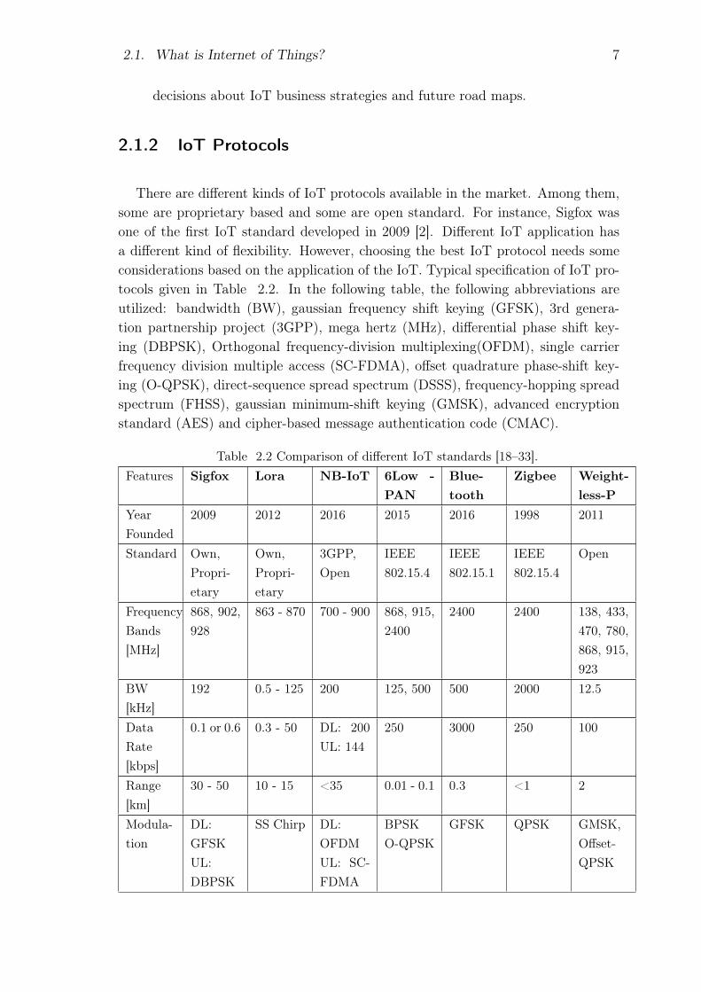
There are different kinds of IoT protocols available in the market. Among them,some are proprietary based and some are open standard. For instance, Sigfox wasone of the first IoT standard developed in 2009 [2]. Different IoT application hasa different kind of flexibility. However, choosing the best IoT protocol needs someconsiderations based on the application of the IoT. Typical specification of IoT pro-tocols given in Table 2.2. In the following table, the following abbreviations areutilized: bandwidth (BW), gaussian frequency shift keying (GFSK), 3rd genera-tion partnership project (3GPP), mega hertz (MHz), differential phase shift key-ing (DBPSK), Orthogonal frequency-division multiplexing(OFDM), single carrierfrequency division multiple access (SC-FDMA), offset quadrature phase-shift key-ing (O-QPSK), direct-sequence spread spectrum (DSSS), frequency-hopping spreadspectrum (FHSS), gaussian minimum-shift keying (GMSK), advanced encryptionstandard (AES) and cipher-based message authentication code (CMAC).
Table 2.2 Comparison of different IoT standards [18–33].Features Sigfox Lora NB-IoT 6Low -
PANBlue-tooth
Zigbee Weight-less-P
YearFounded
2009 2012 2016 2015 2016 1998 2011
Standard Own,Propri-etary
Own,Propri-etary
3GPP,Open
IEEE802.15.4
IEEE802.15.1
IEEE802.15.4
Open
FrequencyBands[MHz]
868, 902,928
863 - 870 700 - 900 868, 915,2400
2400 2400 138, 433,470, 780,868, 915,923
BW[kHz]
192 0.5 - 125 200 125, 500 500 2000 12.5
DataRate[kbps]
0.1 or 0.6 0.3 - 50 DL: 200UL: 144
250 3000 250 100
Range[km]
30 - 50 10 - 15 <35 0.01 - 0.1 0.3 <1 2
Modula-tion
DL:GFSKUL:DBPSK
SS Chirp DL:OFDMUL: SC-FDMA
BPSKO-QPSK
GFSK QPSK GMSK,Offset-QPSK

2.1. What is Internet of Things? 8
Table 2.2 Comparison of different IoT standards [18–33].Features Sigfox Lora NB-IoT 6LowPANBlue-
toothZigbee Weight-
less-PSpreading - - No DSSS FHSS DSSS -Schedu-ling
Uplinkinitiated
Uplinkinitiated
Networksheduled
- Roundrobin
- -
Latency[s]
2.08 1 - 2 <10 8 6 1 very low
DuplexMode
Full Full Half Full Half/Full Half/Full Full
Network LPWAN LPWAN LPWAN WPAN WPAN WPAN LPWANNetworkTopol-ogy
Star Star Star Star,Mesh
P2P STAR,Mesh
Star
TxPower[dBm]
UL: 14DL :27
14 - 27 UE: 23 - 10 8 UE: 14
PowerCon-sumtion[mA]
10 - 50 10 100 20 30 30 Very low
Security AES AES,CMAC
AES AES AES-CCM
AES -128
AES-128/256
Mobility Yes Yes No - Yes Yes YesBatteryLife[Years]
>10 >10 >10 1 - 2 Few days <1 Fewyears
Most importantly, in order to choose the best IoT protocol for a specific application,following consideration should be taken into account:
• Coverage
• Battery life
• QoS and Security
• Cost and Scalability
• Latency and Throughput
• Roaming and User Interface

2.2. IoT Security and Vulnerabilities 9
2.2 IoT Security and Vulnerabilities
Nowadays, security is the biggest concern for internet-based services. In orderto make the IoT more successful in the technology market, it needs to conform toa certain level of security standard. For instance, in a smart home, a smart smokedetector is installed with malicious software. Furthermore, the smoke detector isconnected to the other home electronic devices. If a hacker can get unauthorizedaccess to the smart smoke detector, then the attacker might have access to otherdevices too. Therefore every IoT device must need to meet a certain level of securitystandards. IoT device must have to conform to the following security requirements[34]:
X Access and device authentication control
X Users privacy
X Data security
X Resilience to the malicious attacks
X Connection security
X Failure tolerance
In order to gain unauthorized access to the IoT devices, the attacker or hackercan attack the network system from inside or outside the network. IoT devices arelow-cost device, so IoT operators or users need to be more considerate on how theywill implement security in the IoT devices. An attacker can launch different kindsof attacks on each IoT layer as depicted in Table 2.3.
Table 2.3 IoT threats and vulnerabilities [6,7].IoT layers Threats and VulnerabilitiesBusiness layer Baiting, quid-pro-quo, pretexting, tailgating.User interfacelayer
Cross-site scripting (XSS) attack, command injection attacks,phishing attack, user deception attack, social engineering attack.
Application layer malware attack, overwhelm, reprogram
Processing layer Brute force attack, birthday attack, password attack, SQL injec-tion attack.
Transport layer Mac address flooding, black hole attack, sink hole attack, framecollisions, session hijacking, denial of service (DoS) attacks
Physical layer Device tampering, Radio signal jamming, Spoofing, Signal inter-ference.
In order to protect the IoT network from different kinds of malicious attack, IoToperators and users can take various steps. Few of the most important steps arelisted below:

2.3. IoT Applications 10
(a) Implement a secure authentication, authorization and access control system.
(b) Define a well secure firewall and intrusion prevention (IPS) system.
(c) Encrypt all of the data frames in the transmission path.
(d) Implement a secure storage system and identity management system.
(e) Update device firmware regularly.
2.3 IoT Applications
At the present time, IoT has become one of the most attractive future technol-ogy that can be used for different purposes. For instance, nowadays, nearly everyembedded electronic devices need sensors and operators to operate those devices.Those sensors can IoT connectivity and can be managed more efficiently. IoT is nowable to connect most of the devices in the industry and became a global networkfor devices and machines and provisioned machine to machine (M2M) and device todevice (D2D) communication in an industry. Not only in the industrial cases butalso in other cases, for example, IoT can be used to keep track of home electronicdevices too. In order to save money and energy, electronic devices in every home,for example, refrigerator, light, fan, and air-cooler can be monitored with the helpof IoT. In the same way, IoT is now playing a big role in the smart wearable de-vice, smart city, smart grid, smart health care system, smart agriculture, and smartlogistics service. For example, smart IoT temperature sensor can be used to trackthe temperature of the cargo container that helps the user to take real-time stepsto keep the goods in good condition. To prioritize the use cases of IoT, it can becategorized to two groups as follows: massive IoT and critical IoT [35–37]. Themost common use cases of those two cases tabularized in Table 2.4.
Table 2.4 IoT category.Massive IoT Critical IoTSmart building Traffic controlSmart agriculture Remote health careLogistics tracking Smart gridSmart agriculture Smart industrySmart metering Remote manufacturingCapillary networks Remote surgery
Furthermore, IoT can be referred to as an intelligent network and its applicationalso includes the necessity of intelligent processing of sensors or devices data. IoTapplication server filtered out unnecessary data and store only the valuable data.
2.4. IoT in Global Economy 11
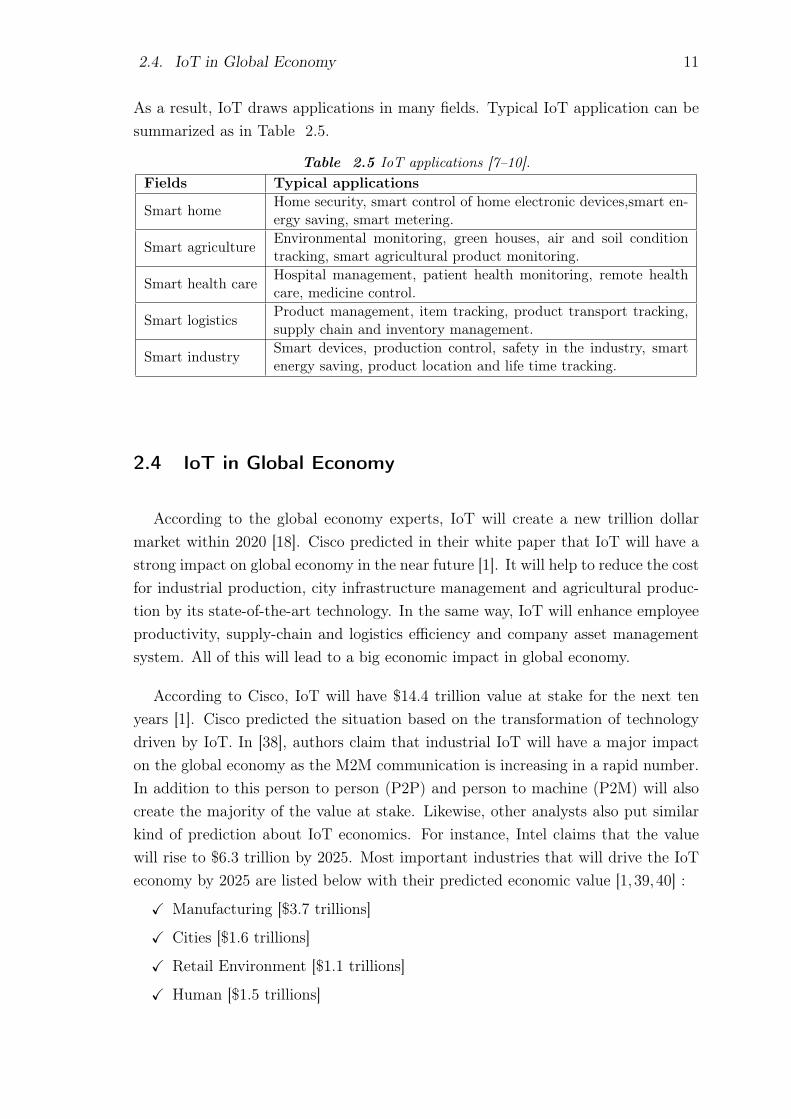
As a result, IoT draws applications in many fields. Typical IoT application can besummarized as in Table 2.5.
Table 2.5 IoT applications [7–10].Fields Typical applications
Smart home Home security, smart control of home electronic devices,smart en-ergy saving, smart metering.
Smart agriculture Environmental monitoring, green houses, air and soil conditiontracking, smart agricultural product monitoring.
Smart health care Hospital management, patient health monitoring, remote healthcare, medicine control.
Smart logistics Product management, item tracking, product transport tracking,supply chain and inventory management.
Smart industry Smart devices, production control, safety in the industry, smartenergy saving, product location and life time tracking.
2.4 IoT in Global Economy
According to the global economy experts, IoT will create a new trillion dollarmarket within 2020 [18]. Cisco predicted in their white paper that IoT will have astrong impact on global economy in the near future [1]. It will help to reduce the costfor industrial production, city infrastructure management and agricultural produc-tion by its state-of-the-art technology. In the same way, IoT will enhance employeeproductivity, supply-chain and logistics efficiency and company asset managementsystem. All of this will lead to a big economic impact in global economy.
According to Cisco, IoT will have $14.4 trillion value at stake for the next tenyears [1]. Cisco predicted the situation based on the transformation of technologydriven by IoT. In [38], authors claim that industrial IoT will have a major impacton the global economy as the M2M communication is increasing in a rapid number.In addition to this person to person (P2P) and person to machine (P2M) will alsocreate the majority of the value at stake. Likewise, other analysts also put similarkind of prediction about IoT economics. For instance, Intel claims that the valuewill rise to $6.3 trillion by 2025. Most important industries that will drive the IoTeconomy by 2025 are listed below with their predicted economic value [1, 39,40] :
X Manufacturing [$3.7 trillions]
X Cities [$1.6 trillions]
X Retail Environment [$1.1 trillions]
X Human [$1.5 trillions]

2.4. IoT in Global Economy 12
X Vehicles [$0.74 trillions]
X Finance and Insurance [$0.5 trillions]
X Health-care [$0.4 trillions]
X Offices [$0.15 trillions]
Statistics from different accredited sources claimed that the IoT will producemost of the economic value to the developed countries [1]. The total IoT economicdistribution shown in Figure 2.3.
Figure 2.3 Distribution of IoT economics around the world [1].
A survey conducted by KRC research group predicted that the number of con-nected devices in smart appliances will be more than 35% within the next fiveyears [41]. Summary of their prediction is given in Figure 2.4.
At present, a lot of IoT projects are implemented in different countries. Examplesof few IoT projects that has been implemented in different countries given below [42]:
(i) Predictive control of vineyards in Pago Ayles winery, Spain.
(ii) Water quality control in the Volga river, Russia by using drones and sensors.
(iii) Smart car parking solution in Montepellier, France.
(iv) Air quality control for healthy lifestyle in Lebanon.
(v) Bins and dumpsters monitoring with ultrasonic sensor to reduce waste collec-tion by 30% in IL, USA.
(vi) Smart lighting system to reduce electricity usage by 80% in United King-dom.

2.5. IoT in Finland 13
Figure 2.4 Number of connected devices in the next five years.
2.5 IoT in Finland
Finland is a Nordic country and its economy is mainly based on science and tech-nology. Therefore IoT will have a strong impact on its economy. As the populationof Finland is very small in comparison with its industrial needs, therefore IoT canplay a major role to overcome this problem [43]. Finland has already deployed fewIoT networks such as Sigfox, LoRaWAN, NB-IoT. A great number of applicationsare already in the market for commercial purposes. For instance, Telia and Postideveloped the world first smart post system using NB-IoT. A smartpost provideinformation in real time, for example, if a mail is dropped in the mailbox, if it is fullor empty and if it has been opened. According to the chief process officer of Posti,Smartpost can save up to 13 million euros per year [44]. It is worth mentioning thata lot of cost saving applications are now under development with the help of severalIoT research program.
Finland has already started Internet of Things research program in 2012. Themain focus of this program is to provide a better IoT management system to supportIoT services and applications. The estimated cost for this program is about 50
million euros [45]. Finnish industrial internet forum (FIIF) is arranging eventsregularly on IoT to support and boost the IoT market. It also provide money fordifferent organizations or institutes to make new IoT products and services. IoTcompanies which are leading the Finland’s IoT market are Ericsson, Elektrobit,Wapice, Corenet, F-Secure, Intel, TeliaSonera, Siemens and Nokia.

14
3. SIGFOX BASED IOT
Sigfox technology was founded by Ludovic Le Moan and Christophe Fourtet in2009 [2]. The company’s headquarters is located in Labège near Toulouse whichis well known as France’s “IoT Valley”. Sigfox is considered one of the most rep-resentative LPWAN systems among other LPWAN schemes [46]. It provides theconnectivity between device and the cloud in a cost efficient manner. In [47], au-thors argued that Sigfox is the most cheap IoT service provider among other IoToperators. Sigfox technology is able to connect billions of devices in its networks.As its approach is to connect the devices to its central cloud infrastructure, thereis no need for roaming services for the end user’s devices. Sigfox devices operate inlow energy thus it can be consider it as an eco-friendly technology.Each Sigfox base station can handle up to three million devices [48]. The manage-ment of these devices is very easy and the number of connected devices can increaseby adding more base stations. Sigfox system has very good indoor and outdoor per-formance and network failure rate is only 12% [49]. Sigfox cell can provide coverageabout 30 - 50 km in rural areas and 3 - 10 km for urban areas. In case of free spaceand line of sight (LOS) connection, signal can travel over 1000 km [50–52].Sigfox key achievement given in Table 3.1 (updated: March 29, 2019).
Table 3.1 Sigfox key achievements [2].Peoples Connected 1 billionCountries Covered 60Areas Covered 5 million km2
Technically, Sigfox signal is highly resistive with respect to noise signal and Fig-ure 3.1 shows that only 8 dB SNR is required to recover the signal. Sigfox technicalspecifications are given in Table 3.2.
3.1 Sigfox Protocol
Sigfox protocol is mainly based on low throughput network (LTN) protocol. Themessage is 12 bytes long and it includes a sequence number for security purposes.

3.1. Sigfox Protocol 15
Figure 3.1 Interference signal impact on Sigfox signal.
Table 3.2 Sigfox technical specifications.
FrequencyBands (MHz)
Europe: 868, Others:902 - 928
Tx Out-putPower
Europe: 14 dB, USA:22 dB
Bandwidth 192 kHz DataRate
100 bps or 600 bps
Modulation Uplink: DBPSK Payload Uplink :12 bytesDownlink: GFSK Downlink: 8 bytes
Power con-sumption
Active: 10 - 50 mA,Idle: 6 nA
Numberof Mes-sages
Per Hour: 6, Per Day:140
Security AES Roamingrequired
No
Sigfox devices send 140 messages (maximum) per day and the rest of the time thedevices stay in the sleeping mode. It helps to operate the device at low powerand provides additional security for the system. The end device can only createcommunication with the base station and transmits each message three times inthree different frequency. Sigfox network protocol uses both time and frequencydiversity. Sigfox base station transmits the signal by using a random frequencyand time division multiple access (RFTDMA). Sigfox protocol structure given inTable 3.3.
Table 3.3 Sigfox protocol stack [11,12].
Application Layer
Transport Layer
MAC (Medium Access Control)Layer
Physical Layer
Physical layer handles the modulation and demodulation of the Sigfox signal.In a Sigfox based communication system, there is no need for signalling messages.

3.2. Modulation and Multiple Access Technique 16
Sigfox uses ultra narrowband (UNB) modulation to send and receive messages. To bespecific, Sigfox sends three messages using multiple channels and the packet durationis 2 ms [53]. The physical layer also handles the framing mechanism process duringtransmission and reception. Sigfox messages are 0 to 12 bytes long. Each Sigfoxmessage frame includes preamble bits, frame synchronization bits, device identifierbits, payload bits, authentication codes and also the frame check sequence (FCS)bits. The generic structure of uplink and downlink frames are given in Table 3.4. Inthe first place, a preamble is used for synchronization purposes and certain bit wordsare used by the receiver to unscramble the bits. This technique removes the needfor additional flags and in addition to this, it leads to the reduction of the packetsize [47,53–56]. Sigfox frames are not encrypted by the Sigfox protocol itself ratherthe encryption is done by the client themselves at the application layer. Applicationlayer also provides other necessary functionality required by the clients and the mostimportant of them are messaging, web-services and the call back function.
Table 3.4 Sigfox frame structure.
UplinkFrame
Preamble(32 bits)
FrameSync(16bits)
DeviceID (32bits)
Payload (0- 96 bits)
MessageAuthen-ticationCode (16 -40bits)
FCS (16bits)
DownlinkFrame
Preamble(32 bits)
FrameSync(13bits)
ECC(32bits)
Payload(0-64 bits)
MessageAuth Code(16bits)
FCS (8bits)
3.2 Modulation and Multiple Access Technique
Sigfox uses DBPSK in the uplink and GFSK in the downlink. In DBPSK mod-ulation, the modulated signal changes its phase shift, when there is a data bit 1,thus provide high spectral efficiency. Due to the noisy communication channel, thetransmitted signal phase shift changes at a very low rate. Therefore, DBPSK isable to provide a reliable way of communication, thus making it a more efficientchoice than other modulation schemes. DBPSK signal modulation scheme shown inFigure 3.2. Practically, there is no need to send data regularly via the downlinkas there is no handshake method available in this technology. But in case of devicefirmware update, a user may send data via downlink.
Sigfox, as well as other ultra narrowband (UNB) technology, uses random fre-quency and time division multiple access (RFTDMA), where nodes (end devices)

3.3. Sigfox Platforms 17
access to the wireless medium randomly both in frequency and time domain withouthaving any containment method. It is an ALOHA-based protocol, which operatesin a certain range of random frequency and time without having any knowledge ofthe channel state. Sigfox chosen this multiple access technology because it offersfollowing benefits [57,58]:
(i) Frequency diversity: Sigfox devices broadcast its one message in three differentfrequency.
(ii) Time diversity: Sigfox devices broadcast its one message in three differenttime.
(iii) Spatial diversity: Each Sigfox message received by more than one base stationat a time.
(iv) Noise robustness and spectrum interference avoidance.
(v) No need for time synchronization and beacon packets.
(vi) Highly energy efficient and energy consumption is nearly zero when there isno transmission.
Figure 3.2 DBPSK modulation.
3.3 Sigfox Platforms
In order to use the Sigfox network, a user needs to have Sigfox network com-patible device known as the Sigfox IoT device. Sigfox IoT devices are normally a

3.3. Sigfox Platforms 18
lightweight device equipped with a battery and pre-installed software and drive bya Sigfox compatible module. However, Sigfox operates in different frequency bandsin different country. Hence, different regions of the world may need different kindof Sigfox device and module. A typical example of Sigfox module and device shownon Figure 3.3. At present, Sigfox divided the whole world into six different re-gion. Each region has unique radio configurations and unique or shared modulesand devices. Sigfox regions specifications and few of the available Sigfox modulesand devices in different regions itemized below:
� Zone: RC1
(i) Countries: Europe, Oman, Iran, South Africa, Tunisia, UAE.
(ii) Modules: WSSFM10R1, RC1682-SIG, WSSFM20R1, UPLYNX Sigfoxverified RCZ1 module, SIPY 14 dB, WSG303S, WSG304S.
(iii) Devices: Water Health Smart Device, NashTag™Mini, NashTag™Poucet,Main-IoT leak guard, All Sense Smart Industry, All Sense Smart city,Water Pressure Smart Device, All Sense Sensor Controller, NexxtenderMobile, Web things AMR, Smart Connect, Water Pulse Smart Deviceetc.
(iv) Other Features: Operating Frequency: 868 - 878.6 MHz, EIRP: 16 dBm,Frame Transmission Time: 2 s.
� Zone: RC2
(i) Countries: USA, Mexico, Brazil.
(ii) Modules: SIPY 22 dB, S01 (SIPY) OEM MODULE 22 dBm.
(iii) Devices: Main-IoT leak guard.
(iv) Other Features: Operating Frequency: 902.1375 - 904.6625 MHz, EIRP:24 dBm, Frame Transmission Time: 350 ms.
� Zone: RC3
(i) Country: Japan.
(ii) Modules: S-WING Sigfox extension board for BOSCH XDK, WF 923,SN10-13, SN10-23, WF931.
(iii) Devices: OTOHunter, Door Opening Sensor, Digital Nano Strain Gauge,Service button RC3, Esense Pro CO2 etc.
(iv) Other Features: Frequency: 922.3 - 923.5 MHz, EIRP: 16 dBm, FrameTransmission Time: 2 s, Listen before talk (LBT).
� Zone: RC4
(i) Country: Latin America, Asia Pacific.

3.4. Sigfox Network Dimensioning and Planning 19
(a) A Sigfox module. (b) A Sigfox device.
Figure 3.3 Example of a Sigfox module and a Sigfox device [2].
(ii) Modules: WSSFM60R4, WSG300S .
(iii) Devices: Connected airwits, Connected pressguard, OneSense Agricul-ture UC16 Irrigation and Soil Salinity Monitoring RC4.
(iv) Other Features: Operating Frequency: 920.1375 - 922.6625 MHz, EIRP:24 dBm, Frame Transmission Time: 350 ms, Frequency hopping.
� Zone: RC5
(i) Country: South Korea.
(ii) Modules: WSG303S RC1/RC3C/RC5.
(iii) Devices: Base for smoke alarm, Marine smart hub RC5.
(iv) Other Features: Operating Frequency: 920.8 - 923.4 MHz, EIRP:14 dBm, LBT.
� Zone: RC6
(i) Country: India.
(ii) Modules: None.
(iii) Devices: Base for smoke alarm GS511 - RC6.
(iv) Other Features: Operating Frequency: 865 - 867 MHz, EIRP: 16 dBm.
3.4 Sigfox Network Dimensioning and Planning
Sigfox is a low power wide area radio network provider for IoT systems. InSigfox based radio network, usually multiple radio base stations are deployed in thecoverage area to provide coverage and connectivity to the IoT devices. Thereforethe QoS of the network depends on the radio network planning and mostly onthe number of deployed base stations. So, network dimensioning and planning isa very important task to set up a wireless network connection between the base

3.4. Sigfox Network Dimensioning and Planning 20
transceiver station (BTS) and the end devices. In addition, it reduces the cost forimplementation of the network and also removes additional complexity. A proposedinitial Sigfox network planning procedure given in Figure 3.4.
Figure 3.4 Sigfox network planning procedures.
3.4.1 Sigfox Network Dimensioning
Since Sigfox network only supports the packet switched data, so a packet switchedtraffic model is needed for the network operation. The traffic model should be basedon a large number of devices because a cell area which is located in a big city couldhave millions of devices and those devices broadcast three copy of each message.According to the Sigfox technical specification, each message is only 12 bytes longand one Sigfox device send maximum 144 messages per day in a random time andrandom frequency. In addition, the attempts of sending messages to the BTS can

3.4. Sigfox Network Dimensioning and Planning 21
be successful or unsuccessful. In this kind of scenario, Bernoulli trial coupled witha binomial distribution can be used to model the uplink success rate [49]. Followingconsideration should be taken into account for the Sigfox device traffic model (uplinktraffic model) [13]:
(i) Categorize the information sent to the network based on importance and size.
(ii) Define the device active and hibernate time in an efficient manner to save theenergy.
(iii) Define the efficient payload size to maximize the use of energy. Allowed pay-load sizes in Sigfox protocol are 1, 2, 8, 12 bytes.
(iv) Compress the payload data using the compression algorithm.
(v) Plan a backup method for a lost message in the transmission path.
(vi) Avoid sending the identical message and for minor change in the repeatedmessage use notification with delta information.
(vii) Place the end device in a most suitable place from where it can easily getconnected to the network.
In order to simulate the desired cell area, a simulation software can be used, forexample, in this thesis MATLAB was used to do all of the simulations. First ofall, choose the lowest possible values of the required parameters and then simulatemultiple times by changing the values to the middle values or average values andfinally for the highest possible values. In order to estimate the coverage and capacity,revise the primary assumptions, and simulate the program for multiple times. Adetail simulation procedures and results using MATLAB are discussed on section 4.3.
3.4.2 Sigfox Network Planning
The aim of radio network planning is to predict and estimate the Sigfox radionetwork coverage and design the network efficiently based on the analysis from thenetwork dimensioning.
(a) Make an initial plan to find the location of the cell site.
(b) Base station antenna parameters play the most important role for the bestpossible coverage. In this case, the antenna type, azimuth angle, tilt angle,altitude, feeder line type selection needs to be considered. Sigfox base stationsare provided by the Sigfox and use Sigfox base station transceiver (SBS-T)Version 2 and 3. Both of them supports only omnidirectional antenna withgain less than 8 dBi [59] and supports bi-directional wireless communication.The Sigfox base station also equipped with a modem, a low noise amplifier(LNA) and a cavity filter to achieve high sensitivity [60].

3.4. Sigfox Network Dimensioning and Planning 22
(c) Define the required gateway parameters and set the DL power to the 27 dBm.
(d) Predict the coverage area and modify required parameter to meet the require-ments.
(e) Find and use propagation models which is best suited to the given area.
(f) Simulate the output data to find network performance.
3.4.3 Sigfox Network Evaluation
In a Sigfox network, QoS found much more comfortable among the LPWANnetworks. In an experiment conducted in Ireland shows that Sigfox end devicesable to sent messages to the base station over a 25 km point to point distance [51].A Sigfox device can successfully send a message to the Sigfox base station withRSSI as low as -145 dB, which distinguished itself from other LPWAN networks.The performance metric of Sigfox networks is path loss, collisions among the datapackets, SNR, RSSI and packet error rate of a large number of devices at Sigfoxspecified frequency. Among them, path loss can be calculated from Equation 3.1.
PL = |RSSI|+ SNR + PTX +GRX + 10n log10(d/do) (3.1)
where,
PL Path loss,PTX Effective isotropic radiated Power,GRX Receiver’s antenna gain,n Path loss exponent,d Distance between the node and the base Station,do Reference distance.
Let us consider a case where a Sigfox device is 5 km away from the base station.In addition, the device is receiving the signal at SNR = 20 dB, RSSI = -122 dBm andpath loss exponent is 2. If the device under test is in free space then, the simulationscenario of theoretical free space path loss and path loss at the described case canbe shown in Figure 3.5.
The link budget is the most important tool for the system-level design of LPWANssystems, which is prepared by calculating all the gains and losses in the transmissionpaths and normally expressed in dB. A link budget analysis among LPWANs inTable 3.5 shows that Sigfox also provides a very good link budget among theLPWANs [61].

3.5. Sigfox Backend, Callbacks and API 23
100 101 102
Distance in logarithmic km
80
90
100
110
120
130
140
150
160
170
180
Path
loss [dB
]
FSL at 868 MHz
Expected Path Loss
Figure 3.5 Comparisons of path losses [3,4].
Table 3.5 LPWANs link budget.
LPWANs Link budget (dB)Sigfox 156LORA 117-156NB-IoT 164Weightless 152
3.5 Sigfox Backend, Callbacks and API
As discussed earlier, Sigfox emerged as not only an IoT technology operator butalso as a complete IoT service solution center. Sigfox devices are made by the Sigfoxcertified companies and also distributed by Sigfox authorized companies. In the firstplace, Sigfox devices sent its messages to the Sigfox network server which is calledSigfox backend 1. In the backend, a user needs to authenticate the Sigfox device andthe user to get the full IoT service.Each Sigfox IoT device is equipped with a unique SigfoxID and a porting authoriza-tion code (PAC) identifier, both of them are hexadecimal numbers. After registeringin the backend server, a user need to authenticate the device with SigfoxID and PACidentifier. The Sigfox backend provides a web-based graphical user interface (GUI)
1. https://backend.sigfox.com

3.5. Sigfox Backend, Callbacks and API 24
for device management and configuration. Furthermore, it is a bridge between enddevices and the user’s where operational support system (OSS) defines the function-ality of the Sigfox backend.
After successful authentication in the Sigfox backend, a user can view the menutab with welcome message and the current Sigfox cloud version release notes asshown in Figure 3.6. After that Sigfox devices need to register to the Sigfox backend
Figure 3.6 Sigfox backend GUI (available at: https://backend.sigfox.com, accessed on:29th March, 2019).
services, which can be done by using SigfoxID and PAC identifier. At this point, auser can group their devices according to the type and functionality of the individualSigfox device. Furthermore, Sigfox backend also provides the following functionality.
(i) New user creation: Sigfox backend allows the user to create new users to accessthe device information based on their rights to read and write predefined duringrole creation policy as illustrated in Figure 3.7. It is obvious that user roles canbe fine-tuned at any time and composed of different custom roles in differentgroups.
(ii) Device: All of the added devices can be seen from Device tab separated bythe unique SigfoxID and it also shows the deleted device, present status of thedevice including average RSSI, SNR and last seen of the device in the online.In addition, by clicking on the individual device ID it is also possible to seethe callback status, statistics for message transfer, RSSI, SNR, and events ornotifications related to that particular device.
(iii) Device type: Device type also provides other important functionalities like thecallbacks creation, statistics for messages, devices status, the location of thedevices and events configuration.

3.5. Sigfox Backend, Callbacks and API 25
(iv) Service map: Sigfox backend also shows the network service map, where thedevice is located. For instance, Figure 3.8 shows the Sigfox network statusin Finland, where the red area represents the regions with the availability ofthree base stations for receiving signals from the Sigfox device and green areafor the two base station and blue for the one base station respectively.
Figure 3.7 Sigfox custom roles on different groups.
3.5.1 Sigfox API
In order to control and manage IoT devices on the Sigfox network, user’s canintegrate their own platform or server with the Sigfox cloud platform. Sigfox back-end has build in application programming interface (API) which works as a bridgebetween those two platforms and implements the data integration. The API’s arebased on HTTPS protocol, following the REST principles (PUT, GET, DELETEor POST) and the payload format is JSON. Even though it does not provide visu-alization facility of the received data but the user can configure their API’s to sendnotifications or data to their external devices or their connected servers. In order touse API, a user need the API access right which can be granted from the group cre-ation functionality. Sigfox API can return different response code for different eventswhich are tabulated in Table 3.6. If a large amount of data retrieved from Sigfoxserver via API request, the reply will be sliced and this is called paging. In [62],Sigfox recommended to use API’s in the recurring task that have rare occurrenceand not to use to pool event based data.

3.5. Sigfox Backend, Callbacks and API 26
Figure 3.8 Sigfox network service map in the reference area [2]. Accessed on: March,2019.
Table 3.6 Sigfox API response codes.
Code Definition200 Successful204 No content400 Illegal argument401 Unauthorized403 Forbidden404 Not found409 Conflict500 Internal server error
3.5.2 Sigfox Callback System
Sigfox IoT devices are small in size and in most of the commercial cases, a lot ofdevices are needed to fulfill the company’s requirement. In those cases, it is hardto check the incoming messages or device status for every device. In addition whenthe number is very big then it is very hard to manage those devices. For instance,if a user needs to send a firmware update to every device then it is hard to up-

3.5. Sigfox Backend, Callbacks and API 27
date devices one after one. In those cases, some well-reputed companies provideeasily manageable IoT devices in a secure way. They also provide options for viewdata in a more efficient way. Some well-known cloud platform service providers areAmazon Web Services (AWS) IoT, AWS Kinesis, Microsoft Azure™ IoT Hub, Mi-crosoft Azure™ Event Hub, IBM Watson™ IoT Platform, Ubidots and Thinger.io.A typical procedure performed in a callback system shown in Figure 3.9. In orderto successfully retrieve data from the Sigfox server to the Sigfox’s own platform oranother cloud platform, a user need to make a callbacks API in the Sigfox serveralong with an HTTP endpoint, where the API must be in a JSON format as anexample illustrated below:
1 {
2 "device" : "{device}",
3 "data" : "{data}",
4 "time" : {time},
5 "snr" : {snr},
6 "rssi" : {rssi},
7 "station": "{station}",
8 "latitude": {lat},
9 "longitude": {lng},
10 "temperature" : {customData#temp}
11 }
Figure 3.9 Sigfox callback schematics.
(i) Callback via E-mail: In the first place, if one or few Sigfox IoT device needsfor a particular project then it can be easily managed by the callback systemvia email services. The messages of the IoT devices sent directly to the user’se-mail address but no downlink message or information can be sent by thisservice. A typical example of email notifications shown in Figure 3.10.
(ii) Callback via Thinger.io: Sigfox supports interaction with many cloud plat-forms, and one of them is Thinger.io 2. At first, a user need to create a data
2. https://thinger.io

3.6. Integration with Other Networks 28
bucket in the Thinger.io website, which will be used as a storage for the incom-ing messages from the Sigfox server. Data bucket can be created for one deviceor one data bucket for the multiple devices, based on the user requirement.Then the user needs to create an access token that will allow the Sigfox serverto communicate with Thinger.io server in a secure way. Finally, a user needs tocreate a custom callback in the Sigfox backend server 3 to push the messagesto the Thinger.io cloud platform. In the Sigfox backend, the callback typeshould be "Data, Uplink", Channel should be "URL", URL pattern shouldbe "https : //api.thinger.io/v1/users/userId/buckets/data", HTTP methodshould be "POST" and header should be "Authorization with the Access To-ken" 4. In this thesis, ThinXtra Xkit device was used to take the necessarymeasurement to test the performance of the Sigfox network in the referencearea. During the measurement, the Xkit device was connected to the Sigfoxserver and then the Thingr.io platform was used as a custom callback server.The dashboard of the callback server interface shows the values retrieved fromthe Sigfox server. For instance, Figure 3.11 and Figure 3.12 are showingRSSI and SNR values obtained from the measurements.
3.6 Integration with Other Networks
Sigfox is most likely the only one IoT operator which has a central database forall of the IoT devices operating on its network. In addition, Sigfox deploys onlyone operator in each country to provide Sigfox network coverage. Sigfox networkcoverage can also be extended through the easy integration with cellular network orsatellite network or with local asymmetric digital subscriber line (ADSL) technologyas shown in Figure 3.13. This might be necessary to make sure that Sigfox devicecan be used in most of the places of the world.
In order to connect the Sigfox devices from any places of the world, a satellite-based Sigfox network integration can be an excellent choice. In this method, a Sigfoxbase station will be connected with a specific satellite and the satellite will also beconnected with the satellite receiver located at Sigfox cloud server. This will alsohelp to provide coverage for a city on an island or in the desert. In contrary, thelatency will be very high as well as the cost. In the same way, a Sigfox base stationcan also be connected to an ADSL router which is connected to the internet serviceprovider (ISP) via the multi-service access node (MSAN). ISP then can forward theSigfox data packet to the Sigfox cloud. The biggest issue in this type of integration
3. https://backend.sigfox.com4. http://docs.thinger.io/sigfox

3.6. Integration with Other Networks 29
Figure 3.10 Sigfox callback using E-mail services.
Figure 3.11 Xkit RSSI graph in Thringer.io platform.
could be the security of the Sigfox data packets as the packets will travel through

3.6. Integration with Other Networks 30
Figure 3.12 Xkit SNR graph in Thringer.io platform.
Figure 3.13 Proposed way of Sigfox network integration.
the third party vulnerable networks. The third and one of the better way could bethe integration with the cellular network, where the cellular core network will opena node to receive the Sigfox data packets and forward those packets to the Sigfoxcloud. The problem in this type of integration could be the system integrationcomplexity and high cost for the service.

3.7. Security and Privacy 31
3.7 Security and Privacy
Security is the biggest concern for the Sigfox based IoT devices. Let us considera case where a Sigfox device is installed in a laboratory to measure temperature.If this device is not secure then, there can be a big accident in the laboratory. Inthe same way, home IoT devices need to be secure otherwise hackers can hack thepersonal files for illegal use. In a worst-case scenario, a small IoT device can beused as a deadly weapon to kill its end users. So IoT devices need to be up-to-datein security matters. A secure IoT system should have four key elements: security,privacy, reliability and reliance.
In [52] and [63], authors point out the fact that Sigfox devices have a low level ofsecurity and have higher potential security risks. However, nowadays, Sigfox devicesare more secured with the end to end device encryption. Moreover, Sigfox devicesare not operated using the internet protocol (TCP/IP) and each device equippedwith the unique device ID. In addition, it is not connected to any particular networkor base station. Sigfox network built in such a way that it can protect itself from thethreats of denial-of-service attacks (DDoS) or massive device cloning. Sigfox devicetransmits to or receives data from the internet. First, an IoT device broadcast amessage in the air then those messages are received by several base stations. Thosemessages are then delivered to the core network. By default, Sigfox devices designedwith a very strict firewall. So it never has the ability to send data to the unauthorizednetwork via the internet as shown in Figure 3.14.
Figure 3.14 Sigfox devices security schematics [5].
Sigfox constructed security of its devices in the following ways [64]:
(1) Each Sigfox device equipped with unique authentication key. Device authen-tication is done with device ID and advanced encryption standard (AES) en-cryption method with no key over the air (OTA) transmission.
3.8. Sigfox Solutions 32
(2) Static manufacturer key, which is unique to every device and used during theregistration of the device.
(3) A unique device ID for all of the device used for the device authentication.
(4) A message integrity code (MIC) which ensures the message sequence. A MICis normally 2 - 5 bytes long.
(5) Finally, the AES - 128 encryption in the application layer.
Encryption, which performed in the application layer, is the responsibility of thecustomer to design an encryption model for their payload. In addition to this, thebase stations also store credentials to communicate with the Sigfox core network.Sigfox backend also stores end devices authentication keys in order to exchange datasecurely. Sigfox messages contain a sequence number that is synchronized with theSigfox cloud for the purpose of resistance against spoofing.
3.8 Sigfox Solutions
In a cellular communication system, a user can send a big amount of data at agreater speed. But the biggest problem is that the cost of cellular service is very high.When the number of the connected device is very high then the cost also increasesproportionally. A practical solution to this problem is Sigfox based services. Sigfoxis the best solution in case it is intended to connect hundreds or millions of devices.Sigfox also provides cloud services, therfore the user can easily view and managetheir devices [65]. A cost comparison study shows that the cost of a SigFox moduleis almost one-third of a LoRa module and one-fifth of a cellular IoT module [66]. Incontrast, Sigfox cannot provide services which require high BW, for example, likevideo streaming, large file transfer, and vehicular crowddensing [67]. On the otherhand, a lot of practical applications that need to transfer a small amount of datacan use Sigfox network. Some of the notable solution of the Sigfox based systemgiven below [68]:
(1) Water monitoring system using Sigfox compliant device.
(2) Occupancy and chair utilization monitoring with SimplePack device.
(3) A cloud-connected sensor provides an easy way to monitor remote assets andcollect data and real-time alarming using Sigfox technology.
(4) Energy management system and indoor air quality monitoring system usingSigfox technology.
(5) Forest fire detection system to prevent forest fire.
(6) Smart waste management system to reduce cost by 60% in cities.

33
4. MEASUREMENT USING XKIT
At present, Sigfox network is used by a lot of IoT operators around the world.According to the latest report from the Sigfox partner network, currently there are631 IoT operator is using Sigfox network and there are 581 products are commerciallyavailable in the market 1. In addition, there are a lot of IoT products, which areunder development to meet market challenges and demands. Sigfox itself does notmanufacture any device, rather it defines the specifications and technical details forthe IoT companies to make devices compatible with the Sigfox network. As Sigfoxuses license-free spectrum and different country reserves license-free frequency bandin different frequency, therefore Sigfox needs to reserve certain frequency band for aspecific region. As a result, Sigfox devices hardware and software specification differsfrom one region to another. The manufacturers of Sigfox device need to follow theSigfox hardware and software specifications. Sigfox radio network divided into sixradio zones worldwide and devices are made according to the regional specifications.There are many technical differences among the regions or zones as described insection 3.3. However, a device may be compatible with one or more regions tooperate. Therefore, first, a device manufacturer needs to design and develop a deviceprototype then make a sample for testing and send them to the Sigfox authority forverification and certification. In this chapter, a Sigfox prototype Thinxtra Xkit isused to evaluate Sigfox system.
4.1 Introduction to Xkit
Thinxtra, one of the Sigfox partner company, founded in 2015 and head officelocated in Australia 2. It is empowering the world of IoT by using Sigfox technology.Thinxtra developed few IoT devices and development kits and one of them is “Thinx-tra Xkit” as shown in Figure 4.1 [5]. Xkit is a development kit or prototype, whichis normally used by the Sigfox developers to test and manipulate Sigfox system.Xkit can be powered in several ways, such as using a 9 V battery or a USB COMport of a computer or with a Raspberry Pi module. This thesis uses Xkit to make
1. https://partners.sigfox.com2. https://www.thinxtra.com/

4.1. Introduction to Xkit 34
necessary indoor and outdoor measurements in the Tampere University, Hervantacampus, Tampere, Finland. The purpose of this measurement is to validate Sigfoxnetwork performance and also make predictions of Sigfox radio network behavior invarying environments. This device was provided by the Connected Finland Oy 3 tothe Electrical Engineering department of Tampere University for research purposes.Connected Finland Oy, a Finnish Sigfox IoT operator, which connects about 85%of the Finnish population and about 69% of the population (Connected Baltics) inEstonia to the Sigfox IoT services [69].
Thinxtra Xkit module includes few sensors and can be driven by Arduino, Ras-berry Pi and also with the Computer. It also includes a USB port and an external8.5cm omni-directional antenna to receive the signal. Xkit is designed to operate infour different Sigfox radio zones. The key features of a Thinxtra Xkit device givenbelow:
(1) Embedded sensors: Temperature, Pressure, Light, Shock and 3D accelerome-ter, 2 LEDs and 1 push button, 1 USB port.
(2) Arduino Uno R3 board.
(3) Operating zones: RCZ1, RCZ2, RCZ3, RCZ4.
(4) Scalable and easy to install.
(5) Provide a fast and easy way to set up a prototype of a Sigfox IoT device.
(6) Cost effective.
Figure 4.1 Thinxtra Xkit development kit.
3. http://www.connectedfinland.fi/
4.2. Xkit Hardware and Software 35
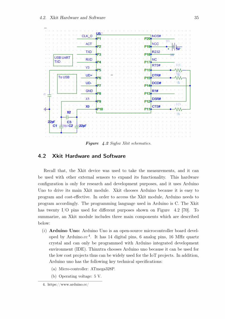
Figure 4.2 Sigfox Xkit schematics.
4.2 Xkit Hardware and Software
Recall that, the Xkit device was used to take the measurements, and it canbe used with other external sensors to expand its functionality. This hardwareconfiguration is only for research and development purposes, and it uses ArduinoUno to drive its main Xkit module. Xkit chooses Arduino because it is easy toprogram and cost-effective. In order to access the Xkit module, Arduino needs toprogram accordingly. The programming language used in Arduino is C. The Xkithas twenty I/O pins used for different purposes shown on Figure 4.2 [70]. Tosummarize, an Xkit module includes three main components which are describedbelow:
(i) Arduino Uno: Arduino Uno is an open-source microcontroller board devel-oped by Arduino.cc 4. It has 14 digital pins, 6 analog pins, 16 MHz quartzcrystal and can only be programmed with Arduino integrated developmentenvironment (IDE). Thinxtra chooses Arduino uno because it can be used forthe low cost projects thus can be widely used for the IoT projects. In addition,Arduino uno has the following key technical specifications:
(a) Micro-controller: ATmega328P.
(b) Operating voltage: 5 V.
4. https://www.arduino.cc/

4.3. Simulation Study of Sigfox Network 36
(c) Input voltage: 7 - 12 V
(d) SRAM: 2 kB.
(e) EEPROM: 1 kB.
(f) Clock speed: 16 MHz.
(g) DC Current per I/O: 20 mA.
(h) DC Current for 3.3 V pin: 50 mA.
(ii) Wisol Module Microchip: Thinxtra Xkit comprises of a radio module madeby Wisol. The Wisol radio module has the following key technical features:
(a) Tx and Rx frequency: 868.13 MHz and 869.525 MHz.
(b) Data rate: Tx and Rx: 100 bps and 600 bps.
(c) Tx output power: 14 dBm (maximum).
(d) Rx sensitivity: -127 dBm.
(e) Input voltage: 1.8 - 3.6 V
(f) Power consumption: Tx: 54 mA, Rx: 15 mA, Idle: 2 μA
The model number of this Wisol microchip is WSSFM10R1AT which rep-resents specific features of this radio module as given in Table 4.1.The pin-diagram and pin-description of Wisol microchip given in Figure 4.3
Table 4.1 Wisol module features.
Code Description Code DescriptionWS WISOL SF SIGFOXM Module 10 Group Model No.R1 Region AT AT Command Version
and Table 4.2 respectively [71].
(iii) 8.5 cm External Antenna: Thinxtra Xkit uses an 8.5 cm external om-nidirectional antenna to successfully send and receive the signal from and toSigfox base stations. It is a low-cost antenna and it radiates the signal equallyin each direction. As a result, Sigfox base station around a node can transmitand receive the signal from any direction more easily.
4.3 Simulation Study of Sigfox Network
In this thesis, the Monte Carlo simulation method was used to evaluate the Sigfoxnetwork. Sigfox device may only transmit 36 seconds per hour thus its time on air is 6seconds. Each Sigfox uplink messages transmitted three times by the device thus theSigfox uplink traffic can be modeled as Bernoulli trial with a binomial distribution.

4.3. Simulation Study of Sigfox Network 37
Figure 4.3 Wisol module schematics.
Table 4.2 WISOL WSSFM10R1 pin description.
1-4,20-22 GND P Ground5,18 NCxx N Do Not Connect
6-10,13,23-26 GPIOxx I/O/PU General Purpose IO11 CPU_LED O CPU Activity Indicator12 RADIO_LED O Radio Activity Indicator14 UARTX O UART Transmit15 UARRX O UART Receive16 RX_LED O Receive Activity Indicator17 TX_LED O Transmit Activity Indicator19 RST_N I/PU Reset Pin21 VDD_IO P Power Supply30 RF_IO A RF Input/ Output
27-29,31 GND P Ground

4.3. Simulation Study of Sigfox Network 38
Sigfox protocol follows a pure ALOHA scheme (random time and random channel)where the probability of a single successful transmission is given by Equation 4.1.So the probability of successful transmission, P is given by Equation 4.2 [72, 73].
p = e−2.G (4.1)
P(X > 0) = 1−(3
0
)p0(1− p)3−0 (4.2)
Time offset (TO) and the packet error rate (PER) can be calculated by Equation 4.3and Equation 4.4 respectively.
TO =ns − (S · np)
T(4.3)
PER =nc
np
(4.4)
where,
G Average transmission attempts,P Number of collision free transmission,T Time interval,p Zero transmission colliding with own attempt,nc Number of collisions,np Number of Packets,ns Number of slots.
A Sigfox base station can support up to one million nodes at a time [59]. In a Sig-fox network, base stations are always connected via a mesh network, which ensuresless packet error rate than other LPWAN protocols. A packet transmission alwaysfails when the devices transmit simultaneously and the time offset is more than thenumber of slots. By considering the above conditions, this thesis presents MAT-LAB based Sigfox network simulations, which shows the behavior of Sigfox networkperformance. Input parameters used in simulations are given in Table 4.3.
Table 4.3 Sigfox network simulation parameters.
Number of devices 1000/10000Number of channels 2000Number of Slots 6000 msTime interval 10 msTime span 60000 msBandwidth 200 kHzFrequency interval 100 Hz
Figure 4.4(a) shows the packet error rate for 1000 devices, where all of the devicesare simultaneously sending data to the Sigfox system through one base station. The

4.4. Measurement and Results 39
packet error rate increases as the number of devices sending data increases. In thesame way, if a single base station is connected to the 10000 nodes, then the packeterror rate also increases as illustrated in Figure 4.4(b). Each sensor message receivedby more than one base station, thus, in that case, the number of packet error rateshould be very low [73].
The results obtained from the next simulations of Sigfox system suggests that thenumber of collisions increased only if the number of transmitting nodes increases.The red dotted line was used to indicate the packet collisions and the green dottedline indicates the successful transmission of the packets. According to the resultsshown on Figure 4.5, it can be shown that there is a few number of red dotted line,which means less collisions among the packets. Numerical analysis of the number ofpackets collided shows that the number of collisions ranges from 17 to 25. Similarly,when the number of devices increases in a cell then the collisions among the packetsalso increased as seen in Figure 4.6.
Overall, these results suggest that the Sigfox system performs very well even ifthere are considerable number of devices connected to one base station. By increas-ing the number of base station in the reference area, the performance of the systemcan be increased.
4.4 Measurement and Results
This thesis includes measurement procedures and analyzes the findings for exper-imental purposes. The hardware of Xkit was set up accordingly and a 9 V batterywas used to power up the device. In order to view the data received by the Sigfoxsystem, E-mail services, and Thinger.io was used as callback services. Two typesof environment was chosen to perform the necessay experiment with Xkit deviceand tools, one outdoor and one was run on the indoor environment of the TAU,Hervanta campus. Following measurement methodologies were used to take themeasurements:
(a) The most suitable places where the Sigfox device may be installed were identified. AsSigfox network operated through the license-free spectrum, therefore other deviceswhich are operating at the same frequency, may create interference. This can providean inaccurate result. Places with frequency interference were identified manually andwere avoided to get the most suitable result.
(b) In order to make the Xkit device portable, it was powered up with a 9 volt batteryand the distance between two measurement points was approximately 10 meters.Before starting the measurement, a printed blueprint of the university buildings [forindoor measurement] and university campus area [for outdoor measurement] was

4.4. Measurement and Results 40
100 200 300 400 500 600 700 800 900 1000
Number of messages / minute
0
1
2
3
4
5
6
7
8
Pac
ket e
rror
rat
e (%
)
Packet error rate(PER)
(a) Sigfox PER for 1000 devices.
1000 2000 3000 4000 5000 6000 7000 8000 9000 10000
Number of messages / minute
0
10
20
30
40
50
60
70
80
90
100
Pac
ket e
rror
rat
e (%
)
Packet error rate(PER)
(b) Sigfox PER for 10000 devices.
Figure 4.4 Sigfox system packet error rate.

4.4. Measurement and Results 41
Figure 4.5 Sigfox spectrum for 1000 devices.
used and unique ID positions were manually marked (For example, P101, P102,P103), where the measurement will be taken. At each measurement point, theswitch of Xkit was pressed manually to force the device to send data to the Sigfoxsystem. Later successful reception of necessary parameters was checked via E-mail.The measurements were taken by visiting the selected measurements points both inindoor and outdoor locations.
(c) In order to get realistic values from the measurements, both open places and deadzones were considered. For example, in case of indoor measurements, a value wastaken in an open place and another value was taken in the places where the signalmost likely obstructed. It helped to plot and map the values in CDF and heat mapaccurately.
(d) In order to take the real-time values in an efficient manner, E-mail callback systemwas used. Another call back system, Thinger.io was also used to recheck the valuesand to observe change through visual representation. In the end, Sigfox back-endserver was used to evaluate the data.
(e) The measured data was recorded in the excel file with respective position ID.
(f) First simulation study of Sigfox network was made to predict and understand thenetwork behavior in different conditions.
(g) The analysis is based on, CDF of the received signal strength, mean of the receivedsignal SNR, and the heat map which was evaluated in the reference area for both

4.4. Measurement and Results 42
Figure 4.6 Sigfox spectrum for 10000 devices.
indoor and outdoor measurements. An analysis of the Sigfox signal behaviors anddifferences between the two measurements was presented for better understanding.
(h) RSSI, SNR and link quality indicator (LQI) are important parameter in wirelessradio connectivity. RSSI can provide a very good estimator for the wireless networkand also provide estimation for the packet reception rate (PRR) and the distancebetween the nodes and the base station [74,75]. RSSI and SNR values were used toevaluate Sigfox network behavior in the reference area.
4.4.1 Indoor Measurement
Sigfox radio network performance in the indoor environment can be evaluatedby surveying the reference area, taking measurements of link speed, interpretingRSSI and SNR values at key locations (for example, open spaces and dead spots).A Sigfox device may be installed in both indoor and outdoor location as requiredby the specific application. In this thesis, indoor measurements were taken in sixbuildings of Tampere University (TAU), Hervanta campus. They are Tietotalo,Sähkötalo, Rakennustalo, Kampusareena, Päätalo, Festia, and Konetalo. In case ofindoor locations, the signal was most likely attenuated by the walls and the floors.

4.4. Measurement and Results 43
Thus the received RSSI and SNR is comparatively low than the outdoor locations.In case of underground locations, signal was obstructed quite often and was lost insome cases. Contrary to this, signal strength and SNR increases with the increasein floor number. The summary of the indoor measurement is tabulated in theTable 4.4.
Table 4.4 Summary of indoor measurements.
Number of measurement points 202Measured parameters SNR and RSSIMaximum average SNR 26.45 dBMinimum RSSI -146 dBmMinimum average SNR 8.66 dBMaximum RSSI -113 dBmNumber of points signal lost 26Number of available base station 0 to 3Standard deviation (SNR) 2.8478Standard deviation (RSSI) 7.9263
The library of the TAU (Hervanta campus) is located in the basement of Kam-pusareena and the signal was lost in all places except under the holes in the rooftopsas shown in the heat map of the library in Figure B.1. Therefore the Sigfox de-vice can not function in a space like the library with the present Sigfox networkcondition.
A measurement study conducted on different floors of Tietotalo building is shownon Figure 4.8. In Figure 4.8, one can clearly see a trend of increased signal strengthon the upper floors. This is happening because the Sigfox signal needs to penetratemore walls and floors to reach the nodes located on the ground floor whereas at thesame time it can easily reach the nodes on the upper floor. This was observed in thecase of other buildings too. Additionally, heat maps of the Sigfox signal measuredon other buildings is shown in Appendix B.
4.4.2 Outdoor Measurement
Outdoor measurements were taken with the set of tools and equipment as de-scribed in section 4.4. The measurements were taken during winter season in Fin-land, and the outside temperature varied between -15 to -5 degree celsius. Therefore,the measurements in received signals were got affected by snowy and cold environ-ment. The measurement were taken by starting from Tietotalo building, and mea-surements points were chosen manually. In outdoor locations, the signals have a

4.4. Measurement and Results 44
-15
0
-14
5
-14
0
-13
5
-13
0
-12
5
-12
0
-11
5
-11
0
-10
5
-10
0
dB
m
Figure 4.7 Heatmap of RSSI values in TAU library, Hervanta campus.

4.4. Measurement and Results 45
-150
-140
-130
-120
-110
-100
dBm
(a) Tietotalo fourth floor.
-150
-140
-130
-120
-110
-100
dBm
(b) Tietotalo third floor.
-150
-140
-130
-120
-110
-100
dBm
(c) Tietotalo second floor.
-150
-140
-130
-120
-110
-100 dBm
(d) Tietotalo first floor.
Figure 4.8 Representation of Sigfox signal strength in different floor of Tietotalo building.

4.4. Measurement and Results 46
different values as expected. The attenuation factor can be small hills, reflectionfrom the building walls, obstruction, and reflection from the nearby trees, and thedistance between the base station and nodes is also important.
Table 4.5 Summary of outdoor measurements.
Number of measurement points 105Measured parameters SNR and RSSIMaximum average SNR 26.96 dBMaximum RSSI -100 dBmMinimum average SNR 22 dBMinimum RSSI -145 dBmNumber of points signal lost 0Number of available base station 1 to 3Standard deviation (SNR) 1.2719Standard deviation (RSSI) 9.4914
After evaluating values received from the Xkit, it is shown that the RSSI andSNR values increase in the open places and decrease in the places close to hills andthe trees. Since location of the Sigfox base station is unknown and hence there mightbe no LOS connection between the base station and the nodes. The heat map ofthe RSSI values obtained from the measurements is shown in Figure 4.9.
-150
-145
-140
-135
-130
-125
-120
-115
-110
-105
-100
dBm
Figure 4.9 Heatmap of RSSI values in TAU, Hervanta campus.

4.5. Results of Analysis 47
4.5 Results of Analysis
This section summarizes the whole measurement results obtained from a Xkitdevice. The area of interest includes both indoor and outdoor places, which help toanalyze and predict the Sigfox system performance in any other locations. Followingthe Sigfox network specifications, as described in Table 3.2 and the simulationstudies of Sigfox network in section 4.3, this thesis compares results obtained inboth indoor and outdoor measurements.
One of the primary metrics of these measurements were the RSSI values whichrepresent the network strength at different points. At one particular point, it wasobserved that RSSI value was different in different trials. One possible cause mightbe, the signal that was received in the successive trials might be different from theprevious base station. In addition to this, the nodes choose different channels atdifferent times. The second metric used to conduct the analysis was SNR values,which shows the Sigfox signal power over the noise signal. Because of multichannelcommunication, the perceived SNR of a single point was also different at differenttimes.
Maximum(Indoor)
Maximum(Outdoor)
Mean(Indoor)
Mean(Outdoor)
Minimum(Indoor)
Minimum(Outdoor)
Case
0
5
10
15
20
25
30
SN
R [
dB
]
Figure 4.10 Comparisons of SNR values in indoor and outdoor measurements.
By observing the plots of SNR values presented in Figure 4.10, it was easy toconclude that the minimum received SNR value of the outdoor measurements was

4.5. Results of Analysis 48
Festia
Kampusareena
KonetaloPäätalo
Rakennustalo
Sähkötalo
Tietotalo
Case
0
5
10
15
20
25
Mea
n S
NR
[d
B]
Figure 4.11 Comparisons of mean SNR values in different building.
higher than the indoor measurements. In case of indoor communication, the Sigfoxsignals need to penetrate ground, walls or rooftops which decreases its strength. ASigfox end device can receive the signal up to a minimum SNR value, which is 8dB. The comparison of maximum SNR value is nearly the same. Because the indoormeasurement points also include places close to outdoor where there might be a glasswall in the middle. In addition, as the outdoor measurement points include a lotof open places compared to the indoor measurement points, the mean values wererelatively higher. Similarly, the mean SNR values of different buildings shown onFigure 4.11. Figure 4.11 indicates that Konetalo and Festia building has the highestmean SNR value. Therefore signal strength was higher in those places than otherplaces. In contrast, Rakennustalo has the lowest mean SNR value. The deviation ofmean SNR value for every building was very small because all buildings are locatedat nearly the same place and have the same environmental conditions.
Another way to analyze the signal distribution is the CDF of the measured signal.The CDF presented in Figure 4.12 shows that in the case of indoor measurementthe distribution of SNR values falls mostly between 17 dB to 25 dB. The range isquite large because of the varying environmental conditions at different measurementpoints. For outdoor measurement, the range of values is limited, and it falls betweenthe values of 22 dB to 27 dB. CDF of measured SNR values of different building is
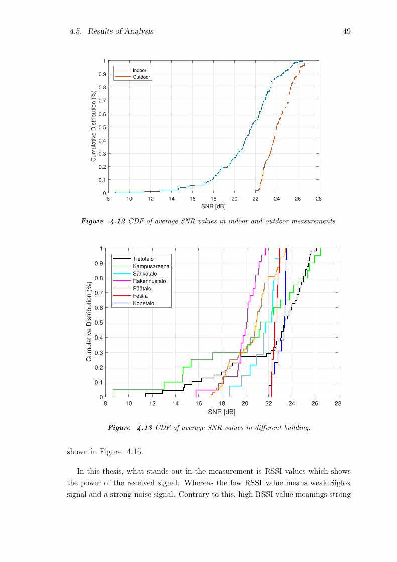
4.5. Results of Analysis 49
8 10 12 14 16 18 20 22 24 26 28
SNR [dB]
0
0.1
0.2
0.3
0.4
0.5
0.6
0.7
0.8
0.9
1
Cum
ula
tive D
istr
ibution (
%)
Indoor
Outdoor
Figure 4.12 CDF of average SNR values in indoor and outdoor measurements.
8 10 12 14 16 18 20 22 24 26 28
SNR [dB]
0
0.1
0.2
0.3
0.4
0.5
0.6
0.7
0.8
0.9
1
Cum
ula
tive D
istr
ibution (
%)
Tietotalo
Kampusareena
Sähkötalo
Rakennustalo
Päätalo
Festia
Konetalo
Figure 4.13 CDF of average SNR values in different building.
shown in Figure 4.15.
In this thesis, what stands out in the measurement is RSSI values which showsthe power of the received signal. Whereas the low RSSI value means weak Sigfoxsignal and a strong noise signal. Contrary to this, high RSSI value meanings strong
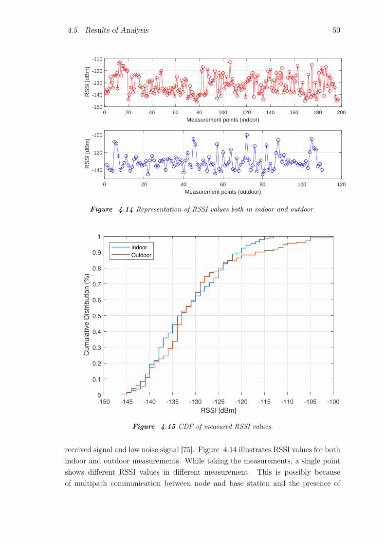
4.5. Results of Analysis 50
0 20 40 60 80 100 120 140 160 180 200
Measurement points (indoor)
-150
-140
-130
-120
-110
RS
SI [
dBm
]
0 20 40 60 80 100 120
Measurement points (outdoor)
-140
-120
-100
RS
SI [
dBm
]
Figure 4.14 Representation of RSSI values both in indoor and outdoor.
-150 -145 -140 -135 -130 -125 -120 -115 -110 -105 -100
RSSI [dBm]
0
0.1
0.2
0.3
0.4
0.5
0.6
0.7
0.8
0.9
1
Cu
mu
lative
Dis
trib
utio
n (
%)
Indoor
Outdoor
Figure 4.15 CDF of measured RSSI values.
received signal and low noise signal [75]. Figure 4.14 illustrates RSSI values for bothindoor and outdoor measurements. While taking the measurements, a single pointshows different RSSI values in different measurement. This is possibly becauseof multipath communication between node and base station and the presence of

4.5. Results of Analysis 51
-150 -145 -140 -135 -130 -125 -120 -115 -110
RSSI [dBm]
0
0.1
0.2
0.3
0.4
0.5
0.6
0.7
0.8
0.9
1
Cum
ula
tive D
istr
ibution (
%)
Tietotalo
Kampusareena
Sähkötalo
Rakennustalo
Päätalo
Festia
Konetalo
Figure 4.16 CDF of RSSI values in different building.
high moisture in the environment [75]. From Figure 4.14, it is clear that outdoormeasurements has high RSSI values than the indoor measurements. Figure 4.15and Figure 4.14 illustrates that the highest possible RSSI value in the referencearea is -110 dBm, which was found in the outdoor location. In addition, most RSSIvalue ranges from -140 dBm to -120 dBm, both in indoor and outdoor locations.Figure 4.16 indicate the distribution of RSSI values in different buildings of TAU,Hervanta campus.

52
5. CONCLUSIONS
As a conclusion for the work carried out in the thesis, the key outline results areintroduced next:
(1) Potential of IoT protocols, applications, security matters and economic im-pacts were investigated.
(2) The architectural aspects of Sigfox based IoT systems were covered with allnecessary information.
(3) Sigfox radio network planning procedures were briefly discussed. Also, MAT-LAB based simulations were presented for better understanding of the Sigfoxradio network planning procedures.
(4) The performance evaluation of the Xkit device is performed, in particular,simulations and practical measurements were taken in the reference area.
5.1 Future Development of Sigfox Network
In order to make the Sigfox network and services more flexible, a lot of develop-ment can be made in its networking technology. For example, a convenient way forSigfox network development can be given as following:
(1) Satellite: Nano satellite or geostationary satellite can be used for better cover-age in large areas. It will also help to connect remote cities or islands together.
(2) Since the Sigfox devices only sense environment, which consumes minimal datatraffic by the way, therefore D2D communication protocols come in handy insuch situations. D2D communication protocols are known for saving devicesenergy while providing better information management system. As a result,for better services, D2D communication protocols are proposed for prospectSigfox systems [76].
(3) Nano antennas: Nano antennas are one of the available options which can beused to provide better indoor coverage. In particular, nano antennas are veryuseful in providing better network coverage in poor network conditions, suchas illustrated in Figure B.1.

5.2. Concluding Words 53
(4) One device for all regions: Sigfox has six radio zones with six different radioconfigurations. Then, one of the possible ways to make the network more costeffective, is to let the device operate at all of the available radio zones.
(5) Improvement of the security system: Recall, Sigfox left the application layerencryption to the end user. Therefore, if the user did not configure the appli-cation layer encryption properly, then the most critical IoT applications mightbe hindered in the process. It is worth mentioning that some researchersfound some Sigfox networks which were potentially vulnerable to high securityrisks [52, 63]. As a result, it can be conclude that more research should befocused on the Sigfox network security.
In addition to the previously mentioned proposals, Sigfox system can be also devel-oped by using M2M communication protocols, not to mention the fact that it canbe also integrated with available cellular networks.
5.2 Concluding Words
The main contribution of this thesis was presenting the Sigfox network behavior inthe reference area using an evaluation kit. The measured parameters were presentedusing tables, CDF graphs and heat maps. It should be noted that, the graphicalpresentations of the measured data and the statistics had some limitations in them,such as:
(1) Because of the limited access right and the limited time given for the comple-tion of the thesis, the indoor measurements were taken in a limited number ofplaces.
(2) Measurements were not taken in fixed discrete distances. However, on aver-age the distances between every two successive points were approximately 10meters.
(3) Because of the limitations stated above, heat maps are not highly accurate.
Also, this thesis discussed the IoT protocol and its applications in details, in additionto the Sigfox technical details and Sigfox network simulations. Not to mentionthat few possible ways for integrating the Sigfox network with other similar radiotechnologies were also presented. Finally, there were some proposals made to developSigfox network including its services.
Sigfox brings a lot of possibilities in the IoT technologies which can be developedfor a better world. This thesis leads to the following future work:
(1) Find out the suitability of the Sigfox devices for specific applications.

5.2. Concluding Words 54
(2) Develop omnidirectional antenna usable in all regions for Sigfox devices.
(3) Develop D2D communication protocol for the Sigfox devices.
(4) Integrate Sigfox network with other available radio technologies.
(5) Design and develop Sigfox nanodevice for the human body.
(6) Design and develop wearable Sigfox IoT device.
55
BIBLIOGRAPHY
[1] C. SYStem, “Embracing the internet of everything to capture your share of$14.4 trillion,” tech. rep., Cisco Systems inc, Cisco Sys Inc, 7 2013. Accessed:2018-09-18.
[2] Sigfox, “Sigfox.” https://www.sigfox.com. Accessed: 2018-09-22.
[3] J. Petajajarvi, K. Mikhaylov, A. Roivainen, T. Hanninen, and M. Pettissalo,“On the coverage of lpwans: range evaluation and channel attenuation modelfor lora technology,” in 2015 14th International Conference on ITS Telecom-munications (ITST), pp. 55–59, Dec 2015.
[4] J. Säe, “Macro cell capacity in mobile networks,” Master’s thesis, TampereUniversity of Technology, 1 2012. Examiner: Prof. Jukka Lempainen.
[5] Sigfox, “Make things come alive in a secure way,” tech. rep., Sigfox, 2 2017.Accessed: 2018-10-2.
[6] L. Malisa, Security of User Interfaces: Attacks and Countermeasures. PhDthesis, ETH Zurich, 2017.
[7] M. M. Hossain, M. Fotouhi, and R. Hasan, “Towards an analysis of securityissues, challenges, and open problems in the internet of things,” in 2015 IEEEWorld Congress on Services, pp. 21–28, June 2015.
[8] T. Saarikko, U. H. Westergren, and T. Blomquist, “The internet of things: Areyou ready for whats coming?,” Business Horizons, vol. 60, no. 5, pp. 667–676,2017.
[9] G. S. Matharu, P. Upadhyay, and L. Chaudhary, “The internet of things: Chal-lenges amp;amp; security issues,” in 2014 International Conference on EmergingTechnologies (ICET), pp. 54–59, Dec 2014.
[10] S. Chen, H. Xu, D. Liu, B. Hu, and H. Wang, “A vision of iot: Applications,challenges, and opportunities with china perspective,” IEEE Internet of ThingsJournal, vol. 1, pp. 349–359, Aug 2014.
[11] Sigfox, “Sigfox protocols.” https://www.youtube.com/watch?v=tGmFgaxKPRU.Accessed: 2018-09-22.
[12] G. Ferré and E. P. Simon, “An introduction to Sigfox and LoRa PHY and MAClayers.” working paper or preprint, Apr. 2018.
[13] Sigfox, “Sigfox device cookbook: communication configuration,” tech. rep., Sig-fox, 11 2018. url: www.build.sigfox.com/sigfox-device-cookbook.

BIBLIOGRAPHY 56
[14] M. People, “Missing people in britian.” https://www.missingpeople.org.uk/about-us/about-the-issue/research/76-keyinformation2.html. Ac-cessed: 2018-09-12.
[15] O. Stevenson, H. Parr, P. Woolnough, and N. Fyfe, “Geographies of missingpeople: Processes, experiences, responses [online],” University of Glasgow, 2013.
[16] H. M. Layson Jr, “Body worn active and passive tracking device,” Jan. 11 2000.US Patent 6,014,080.
[17] A. McEwen and H. Cassimally, Designing the Internet of Things. Wiley, 2013.
[18] Cisco, “The internet of everything global private sector economic analysis,” tech.rep., Cisco Systems, Cisco Inc, 7 2013. Accessed: 2018-09-18.
[19] H. Al-Kashoash and A. Kemp, Comparison of 6LoWPAN and LPWAN for theInternet of Things. Australian Journal of Electrical and Electronics Engineer-ing, 12 2017.
[20] Huawei, “Nb-iot, enabling new business oppurtunities,” Huawei Magazine, 2016.Publisher: Huawei.
[21] J. Gozalvez, “New 3gpp standard for iot [mobile radio],” IEEE Vehicular Tech-nology Magazine, vol. 11, no. 1, pp. 14–20, 2016.
[22] A. D. Zayas and P. Merino, “The 3gpp nb-iot system architecture for the in-ternet of things,” in 2017 IEEE International Conference on CommunicationsWorkshops (ICC Workshops), pp. 277–282, May 2017.
[23] K. Mochizuki, K. Obata, K. Mizutani, and H. Harada, “Development and fieldexperiment of wide area wi-sun system based on ieee 802.15. 4g,” in 2016 IEEE3rd World Forum on Internet of Things (WF-IoT), pp. 76–81, IEEE, 2016.
[24] H. Kroll, M. Korb, B. Weber, S. Willi, and Q. Huang, “Maximum-likelihood de-tection for energy-efficient timing acquisition in nb-iot,” in 2017 IEEE WirelessCommunications and Networking Conference Workshops (WCNCW), pp. 1–5,March 2017.
[25] J. Lin, Z. Shen, and C. Miao, “Using blockchain technology to build trust insharing lorawan iot,” in Proceedings of the 2nd International Conference onCrowd Science and Engineering, pp. 38–43, ACM, 2017.
[26] N. Sornin, M. Luis, T. Eirich, T. Kramp, and O. Hersent, “Lorawan specifica-tion,” LoRa alliance, 2015.
[27] R. S. Sinha, Y. Wei, and S.-H. Hwang, “A survey on lpwa technology: Lora andnb-iot,” Ict Express, vol. 3, no. 1, pp. 14–21, 2017.
[28] IEEE, “Ieee standard for low-rate wireless networks,” IEEE Std 802.15.4-2015(Revision of IEEE Std 802.15.4-2011), pp. 1–709, April 2016.

BIBLIOGRAPHY 57
[29] S. Bluetooth, “Bluetooth specification,” 2003.
[30] B. Specification, “Version 1.0,” JSR, vol. 168, 2003.
[31] J.-S. Lee, Y.-W. Su, and C.-C. Shen, “A comparative study of wireless proto-cols: Bluetooth, uwb, zigbee, and wi-fi,” in Industrial Electronics Society, 2007.IECON 2007. 33rd Annual Conference of the IEEE, pp. 46–51, Ieee, 2007.
[32] A. ZigBee, “Zigbee-2006 specification,” http://www. zigbee. org/, 2006.
[33] W. Webb, “Weightless technology an overview,” Mar, vol. 28, pp. 1–16, 2012.
[34] S. Babar, P. Mahalle, A. Stango, N. Prasad, and R. Prasad, “Proposed securitymodel and threat taxonomy for the internet of things (iot),” in InternationalConference on Network Security and Applications, pp. 420–429, Springer, 2010.
[35] O. Novo, N. Beijar, M. Ocak, J. Kjällman, M. Komu, and T. Kauppinen, “Cap-illary networks - bridging the cellular and iot worlds,” in 2015 IEEE 2nd WorldForum on Internet of Things (WF-IoT), pp. 571–578, Dec 2015.
[36] Qualcomm, Qualcomm IoT. Qualcomm, 1 ed., 9 2018.
[37] D. M. Benjillali, “Itu iot presentation.” https://www.itu.int/en/ITU-D/Regional-Presence/ArabStates/Documents/events/2017/IoTSMW/Presentations-IoT/Session1/IoT4SSC_Session_1_Benjillali.pdf. Ac-cessed: 2018-09-19.
[38] R. Sanchez-Iborra and M.-D. Cano, “State of the art in lp-wan solutions forindustrial iot services,” Sensors, vol. 16, no. 5, p. 708, 2016.
[39] E. Guillén, J. Sánchez, and L. R. López, “Iot protocol model on healthcare mon-itoring,” in VII Latin American Congress on Biomedical Engineering CLAIB2016, Bucaramanga, Santander, Colombia, October 26th-28th, 2016, pp. 193–196, Springer, 2017.
[40] Statista. https://www.statista.com/statistics/580778/worldwide-internet-of-things-economic-impact-forecast/. Accessed:2018-10-3.
[41] K. R. Group, “Gsma: The impact of the internet of things: The connectedhome,” tech. rep., KRC Research Lab, 7 2013.
[42] L. projects. http://www.libelium.com/resources/case-studies/. Ac-cessed: 2018-12-10.
[43] H. Hernesniemi, M. Lammi, P. Ylä-Anttila, and P. Rouvinen, “Advantagefinland.-the future of finnish industries,” tech. rep., The Research Institute ofthe Finnish Economy, 1996.
[44] S. projects. https://www.teliacompany.com/en/news/news-articles/2018/posti-and-telia-pilot-worlds-first-smart-mailbox-with-nb-iot/.Accessed: 2018-12-22.

BIBLIOGRAPHY 58
[45] F. Projects. https://fiif.fi/. Accessed: 2018-12-20.
[46] D. M. Hernandez, G. Peralta, L. Manero, R. Gomez, J. Bilbao, and C. Zubia,“Energy and coverage study of lpwan schemes for industry 4.0,” in 2017 IEEEInternational Workshop of Electronics, Control, Measurement, Signals and theirApplication to Mechatronics (ECMSM), pp. 1–6, May 2017.
[47] S. S. Description. https://datatracker.ietf.org/meeting/97/materials/slides-97-lpwan-25-sigfox-system-description-00. Accessed: 2018-12-23.
[48] O. J. JOSEPH, “Ultra-narrowband internet-of-things technologies,” Master’sthesis, Tampere University of Technology, 11 2017. Examiner: Prof. MarkkuRenfors.
[49] B. Vejlgaard, M. Lauridsen, H. Nguyen, I. Z. Kovacs, P. Mogensen, andM. Sorensen, “Coverage and capacity analysis of sigfox, lora, gprs, and nb-iot,”in 2017 IEEE 85th Vehicular Technology Conference (VTC Spring), pp. 1–5,June 2017.
[50] Sigfox, “One network a billion dreams,” tech. rep., Sigfox, 1 2018. M2M andIoT redefined through cost effective and energy optimized connectivity.
[51] K. E. Nolan, W. Guibene, and M. Y. Kelly, “An evaluation of low powerwide area network technologies for the internet of things,” in 2016 Interna-tional Wireless Communications and Mobile Computing Conference (IWCMC),pp. 439–444, Sep. 2016.
[52] M. Centenaro, L. Vangelista, A. Zanella, and M. Zorzi, “Long-range communi-cations in unlicensed bands: the rising stars in the iot and smart city scenarios,”IEEE Wireless Communications, vol. 23, pp. 60–67, October 2016.
[53] H. Mroue, A. Nasser, and S. Hamrioui, “Mac layer-based evaluation of iot tech-nologies: Lora, sigfox and nb-iot,” in MAC layer-based evaluation of IoT tech-nologies, May 2018.
[54] Sigfox, “Sigfox verified modem specification for rc1-udl-enc,” tech. rep., Sigfox,9 2018. Version 3.7.1.
[55] S. Al-Sarawi, M. Anbar, K. Alieyan, and M. Alzubaidi, “Internet of things (iot)communication protocols: Review,” in 2017 8th International Conference onInformation Technology (ICIT), pp. 685–690, May 2017.
[56] G. Margelis, R. Piechocki, D. Kaleshi, and P. Thomas, “Low throughput net-works for the iot: Lessons learned from industrial implementations,” in 2015IEEE 2nd World Forum on Internet of Things (WF-IoT), pp. 181–186, Dec2015.

BIBLIOGRAPHY 59
[57] G. G. Ribeiro, L. F. de Lima, L. Oliveira, J. J. Rodrigues, C. N. Marins, andG. A. Marcondes, “An outdoor localization system based on sigfox,” in 2018IEEE 87th Vehicular Technology Conference (VTC Spring), pp. 1–5, IEEE,2018.
[58] C. Goursaud and J.-M. Gorce, “Dedicated networks for iot: Phy/mac state ofthe art and challenges,” EAI endorsed transactions on Internet of Things, 2015.
[59] S. B. P. Antoine, Sigfox SBST3 Product Manual. Sigfox, 1 ed., 12 2017.
[60] X. Zhang, A. Andreyev, C. Zumpf, M. C. Negri, S. Guha, and M. Ghosh,“Thoreau: A subterranean wireless sensing network for agriculture and the envi-ronment,” in 2017 IEEE Conference on Computer Communications Workshops(INFOCOM WKSHPS), pp. 78–84, May 2017.
[61] V. Petrov, K. Mikhaylov, D. Moltchanov, S. Andreev, G. Fodor, J. Torsner,H. Yanikomeroglu, M. Juntti, and Y. Koucheryavy, “When iot keeps people inthe loop: A path towards a new global utility,” IEEE Communications Maga-zine, vol. 57, pp. 114–121, January 2019.
[62] Sigfox, Sigfox API usage. Sigfox, 1 ed., 9 2017.
[63] N. Poursafar, M. E. E. Alahi, and S. Mukhopadhyay, “Long-range wireless tech-nologies for iot applications: a review,” in 2017 Eleventh International Confer-ence on Sensing Technology (ICST), pp. 1–6, IEEE, 2017.
[64] R. Fujdiak, P. Blazek, K. Mikhaylov, L. Malina, P. Mlynek, J. Misurec, andV. Blazek, “On track of sigfox confidentiality with end-to-end encryption,” inProceedings of the 13th International Conference on Availability, Reliability andSecurity, p. 19, ACM, 2018.
[65] Z. D. R. Gnimpieba, A. Nait-Sidi-Moh, D. Durand, and J. Fortin, “Using inter-net of things technologies for a collaborative supply chain: Application to track-ing of pallets and containers,” Procedia Computer Science, vol. 56, pp. 550 –557, 2015. The 10th International Conference on Future Networks and Commu-nications (FNC 2015) / The 12th International Conference on Mobile Systemsand Pervasive Computing (MobiSPC 2015) Affiliated Workshops.
[66] A. Azari, Serving IoT Communications over Cellular Networks Challenges andSolutions in Radio Resource Management for Massive and Critical IoT Com-munications. PhD thesis, KTH, Sweden, 11 2018.
[67] V. Petrov, A. Samuylov, V. Begishev, D. Moltchanov, S. Andreev,K. Samouylov, and Y. Koucheryavy, “Vehicle-based relay assistance for oppor-tunistic crowdsensing over narrowband iot (nb-iot),” IEEE Internet of ThingsJournal, vol. 5, pp. 3710–3723, Oct 2018.

BIBLIOGRAPHY 60
[68] P. Di Gennaro, D. Lofú, D. Vitanio, P. Tedeschi, and P. Boccadoro, “Waters: Asigfox-compliant prototype for water monitoring,” Internet Technology Letters,p. e74, 2016.
[69] C. F. Oy, “Thinxtra xkit from connected finland oy.” http://www.connectedfinland.fi/. Accessed: 2018-12-31.
[70] Thinxtra, “Xkit module data sheet.” https://github.com/Thinxtra. Ac-cessed: 2018-12-30.
[71] Wisol, Wisol Module Data Sheet. Wisol, http://www.wisol.co.kr/, 12 ed., 52017. Accessed: 2018-12-31.
[72] N. Abramson, “The aloha system: another alternative for computer commu-nications,” in Proceedings of the November 17-19, 1970, fall joint computerconference, pp. 281–285, ACM, 1970.
[73] N. I. Osman and E. B. Abbas, “Simulation and modelling of lora and sigfoxlow power wide area network technologies,” in 2018 International Conferenceon Computer, Control, Electrical, and Electronics Engineering (ICCCEEE),pp. 1–5, Aug 2018.
[74] K. Srinivasan and P. Levis, “Rssi is under appreciated,” in Proceedings of thethird workshop on embedded networked sensors (EmNets), vol. 2006, Cambridge,MA, USA., 2006.
[75] K. Benkic, M. Malajner, P. Planinsic, and Z. Cucej, “Using rssi value for dis-tance estimation in wireless sensor networks based on zigbee,” in 2008 15thInternational Conference on Systems, Signals and Image Processing, pp. 303–306, IEEE, 2008.
[76] A. Prasad, K. Samdanis, A. Kunz, and J. Song, “Energy efficient device discov-ery for social cloud applications in 3gpp lte-advanced networks,” in 2014 IEEESymposium on Computers and Communications (ISCC), pp. 1–6, June 2014.

61
A. APPENDIX A: MATLAB CODE FOR THE
FSL SIMULATION
1 clc;
2 clear all;
3 close all;
4
5 distance= 0:1:30; % distance to be measured
6 % Calculating Free space pathloss
7 FSL=32.4+20.*log10(distance)+20*log10(868);
8 d=5; % Distance between base station and end device
9 n=2; % path loss exponent
10 rssi=122; % RSSI level
11 snr=20; % Signal to noise ratio
12 ptx=14; % Effective Isotropic Radiated Power
13 grx=0; % Receiver's antenna gain
14 f=distance/d; % Just for simplification
15 % Calculating Normal sigfox based system pathloss
16 sigfox_path_loss= rssi+snr+ptx+grx+10*n*log10(f);
17 figure()
18 semilogx(distance,FSL,'b−−o',distance,sigfox_path_loss,...19 'LineWidth',2);
20 title('Path Loss at Sigfox Radio Network')
21 xlabel('Distance in Logarithmic KM')
22 ylabel('Path loss [dB]')
23 ylim([80 180])
24 legend('FSL at 968MHz','Expected Path ...
Loss','Location','southeast')
25 grid on

62
B. HEATMAP OF RSSI VALUES IN
DIFFERENT BUILDINGS OF TAU, HERVANTA
CAMPUS
-150
-145
-140
-135
-130
-125
-120
-115
-110
-105
-100
dBm
Figure B.1 Heatmap of RSSI values in TAU Päätalo building (first floor), Hervantacampus.

Appendix B. Heatmap of RSSI values in different buildings of TAU, Hervanta campus63
-150
-145
-140
-135
-130
-125
-120
-115
-110
-105
-100
dBm
Figure B.2 Heatmap of RSSI values in TAU Päätalo building (ground floor), Hervantacampus.

Appendix B. Heatmap of RSSI values in different buildings of TAU, Hervanta campus64
-150
-145
-140
-135
-130
-125
-120
-115
-110
-105
-100
dBm
Figure B.3 Heatmap of RSSI values in TAU Rakennustalo building (first floor), Hervantacampus.

Appendix B. Heatmap of RSSI values in different buildings of TAU, Hervanta campus65
-150
-145
-140
-135
-130
-125
-120
-115
-110
-105
-100
dBm
Figure B.4 Heatmap of RSSI values in TAU Sähkötalo building (first floor), Hervantacampus.

Appendix B. Heatmap of RSSI values in different buildings of TAU, Hervanta campus66
-150
-145
-140
-135
-130
-125
-120
-115
-110
-105
-100
dBm
Figure B.5 Heatmap of RSSI values in a part of TAU Festia building (first floor), Her-vanta campus.

Appendix B. Heatmap of RSSI values in different buildings of TAU, Hervanta campus67
-150
-145
-140
-135
-130
-125
-120
-115
-110
-105
-100
dBm
Figure B.6 Heatmap of RSSI values in a part of TAU Konetalo building (first floor),Hervanta campus.

Appendix B. Heatmap of RSSI values in different buildings of TAU, Hervanta campus68
-15
0
-14
5
-14
0
-13
5
-13
0
-12
5
-12
0
-11
5
-11
0
-10
5
-10
0
dB
m
Figure B.7 Heatmap of RSSI values in TAU Kampusareena (first floor) building, Her-vanta campus.

Appendix B. Heatmap of RSSI values in different buildings of TAU, Hervanta campus69
-15
0
-14
5
-14
0
-13
5
-13
0
-12
5
-12
0
-11
5
-11
0
-10
5
-10
0
dB
m
Figure B.8 Heatmap of RSSI values in TAU Kampusareena (second floor) building,Hervanta campus.