md-10-194 queensland rail official undert… · uses a railway track, including any loading on such...
TRANSCRIPT

Version: 4.1
Updated: 04/09/2017 Policy: Safety Policy
Interface Standards
MD-10-194 QUEENSLAND RAIL OFFICIAL

QUEENSLAND RAIL
Standard - Interface Standards
Document History
Document information
Current Version 4.1
First Released 01 July 2010
Last Updated 04 September 2017
Review Frequency Annually
Review Before 04 September 2018
Document Authoriser Chief Executive Officer (CEO)
Functional Owner Senior Manager Rail Safety (SM RS)
Content Developer Senior Manager Rail Safety (SM RS)
Review Stakeholders Safety Discipline Heads, Operational Managers, Network Access, Access Revenue
Audience All employees, contractors, consultants and others listed in Section 3.1
Document amendment history
Version DateSection(s)
AmendedSummary of Amendment
4.1 4/09/2017 Whole documentRemoved Rail Safety Act 2010 and referred to Rail Safety
National Law (Queensland) Act 2017
4.0 23/07/2014 All Reformatting for new Queensland Rail template, titles aligned to
new Org. Structure.
3.1 11/12/2012 Module 1 Details of Reference Rolling Stock Outlines and new business
structure added.
3.0 4/07/2012 All Reformatting for new Queensland Rail template and renumbered
from SAF/STD/0145/INF to MD-10-194. Version history
continued for continuity. Minor errors corrected.
2.0 11/01/2012 All Reformatting and relabelling for Queensland Rail.
Modules 1 and 2 substantially changed. Document control
modules added to whole document.
1.0 1/07/2010 New issue Previously this document was version 1.0 for QR Network. It has
now been adopted by Queensland Rail as SAF/STD/0145/INF
version 1.0.
MD-10-194 (Version 4.0)
_______________________________________________________________________________________________________________
QUEENSLAND RAIL OFFICIAL Page 13 of 14

QUEENSLAND RAIL
Standard - Interface Standards
Table of Contents
Document History
1 What this Standard is about 4
2 Why this Standard is important 5
3 What the scope of this Standard is 6
3.1 Who this Standard applies to 6
3.2 Who should read and understand this Standard? 6
3.3 What is out of scope for this Standard 6
4 Responsibilities 7
5 Terms and Definitions 8
6 What the Requirements of this Standard are 10
7 Appendix 1 - Related documents 12
Module 1 Infrastructure
Module 2 Rolling Stock
Module 3 Safeworking
MD-10-194 (Version 4.1)
_______________________________________________________________________________________________________________
QUEENSLAND RAIL OFFICIAL Page 3 of 14

QUEENSLAND RAIL
Standard - Interface Standards
rolling stock operating on Queensland Rail rail infrastructure, and
the connection between Queensland Rail rail infrastructure and other rail infrastructure
Module 1 Infrastructure
Module 2 Rolling Stock
Module 3 Safeworking
The modules listed below are contained in this standard:
1 What this Standard is about
This standard sets the minimum safety interface standards for:
MD-10-194 (Version 4.0)
_______________________________________________________________________________________________________________
QUEENSLAND RAIL OFFICIAL Page 4 of 14

QUEENSLAND RAIL
Standard - Interface Standards
2 Why this Standard is important
This standard prescribes the minimum requirements for designing and maintaining network
infrastructure and rolling stock to manage the safety interface risks between rolling stock operations
and the network.
This standard assists Queensland Rail to meet its obligations under the Rail Safety National Law
(Queensland) Act 2017.
MD-10-194 (Version 4.1)
_______________________________________________________________________________________________________________
QUEENSLAND RAIL OFFICIAL Page 5 of 14

QUEENSLAND RAIL
Standard - Interface Standards
all rolling stock operations on Queensland Rail rail infrastructure
connecting rail infrastructure at the defined connection point to Queensland Rail rail
infrastructure
every Queensland Rail employee (whether permanent, temporary or casual)
every Queensland Rail contractor or consultant
everyone who does work for Queensland Rail, while they are doing work for Queensland Rail
third party operators
connecting rail infrastructure managers
transfer facility managers, and
everyone who comes onto Queensland Rail’s premises other than public areas.
This standard does not apply to areas where Queensland Rail is not the Rail Infrastructure
Manager.
This standard does not apply to level crossing interfaces between rail and road traffic.
If this applies, Queensland Rail expects you to understand and comply with this Standard and
related documents from Queensland Rail’s Policy Framework that are relevant to your work,
including Queensland Rail’s Code of Conduct.
3.3 What is out of scope for this Standard
3 What the scope of this Standard is
3.1 Who this Standard applies to
This Standard applies to:
3.2 Who should read and understand this Standard?
Any of the people referred to in Section 3.1 who need to make use of this Standard for work
purposes.
This standard applies to:
MD-10-194 (Version 4.0)
_______________________________________________________________________________________________________________
QUEENSLAND RAIL OFFICIAL Page 6 of 14

QUEENSLAND RAIL
Standard - Interface Standards
4 Responsibilities
Who
Board
communicating Queensland Rail’s vision, and the importance of the Standard,
to all Queensland Rail personnel
responding to recommendations made when the Standard is reviewed, to
ensure the Standard remains up to date and relevant to Queensland Rail
develop and implement related documents and processes to ensure this
Standard is reflected in Queensland Rail’s day to day operations
establish and maintain processes to provide assurance to the CEO that this
Standard is being followed by Queensland Rail
review this Standard annually, and provide recommendations to the CEO
Senior Manager Network
Commercial, Access and Business
Strategy
support and communicate the Standard to their employees, contractors and
consultants to ensure they understand the Standard
demonstrate compliance with the Standard
All employees, contractors,
consultants and others listed in
Section 3.1
Principal Engineer Rolling Stock,
Access and Business Strategy Must:
Everyone who needs to make use of this Standard for work purposes must
understand and comply with this Standard.
The following establishes the broad accountabilities and responsibilities of the key internal
stakeholders applicable to this Standard.
Must assist the CEO with the implementation of this Standard and by extension
the related Policy, by leading the implementation of this Standard in their
respective functions, everywhere, every day.
Are also accountable for ensuring this Standard has been implemented and
complied with.
Executive Leadership Team (ELT)
Executive General Manager
Access and Business Strategy
Chief Executive Officer (CEO
Leads Queensland Rail’s implementation of and compliance with the related
Policy, by:
As the Functional Owner approves this Standard and must:
Is the Content Developer, on behalf of the Functional Owner.
This role is unique to this Standard and will provide subject matter expertise and
technical advice to the Content Developer.
What
Responsible for the approval of related Policy in accordance with legal and
regulatory obligations, and to enable Queensland Rail’s pursuit of opportunities
aligned with its vision and values in an ethical and responsible manner.
Responsible for authorising the commitments in this Standard.
MD-10-194 (Version 4.1)
_______________________________________________________________________________________________________________
QUEENSLAND RAIL OFFICIAL Page 7 of 14

QUEENSLAND RAIL
Standard - Interface Standards
5 Terms and Definitions
The following key terms and definitions apply to this Standard
Term Definition Source
On-Track Vehicle (OTV)Rolling stock used for infrastructure maintenance eg section
cars, on-track machinery.
Queensland Rail
Business Glossary
A table outlining activities and roles of different stakeholders
in relation to those activities identifying who is:
Responsible – who does the work
Accountable – who is required to ensure the work is
done adequately
Consulted – who is asked for their input, and
Informed – who must be told about the work.
RISSB
Abbreviation for ‘Railway Industry Safety and Standards
Board’. A wholly owned entity of the Australasian Railway
Association (ARA), responsible for development and
management of the Australian Code of Practice (ACOP).
RISSB - Glossary of
Railway Terminology -
Guideline
Road-Rail Vehicle (RRV)
A vehicle that can travel on a road and can also travel on rail
by use of a rail wheel guidance system. It can readily be
transferred from one mode to the other without additional
facilities.
Queensland Rail
Business Glossary
Rolling Stock
Any vehicle that operates on, or intends to operate on, or
uses a railway track, including any loading on such a vehicle,
but excluding a vehicle designed for both on- and off-track
use when not operating on the track.
Rolling stock is a collective term for a large range of rail
vehicles of various types, including locomotives, freight
wagons, passenger cars, track machines and road-rail
vehicles.
RISSB - Glossary of
Railway Terminology -
Guideline
Uncontrolled DocumentA printed or electronic copy of a document which is not
maintained or updated.
RACI Matrix
MD-10-194 (Version 4.0)
_______________________________________________________________________________________________________________
QUEENSLAND RAIL OFFICIAL Page 8 of 14

QUEENSLAND RAIL
Standard - Interface Standards
6.1 Interface Principles
6.1.1 Queensland Rail will maintain its rail infrastructure and connecting rail infrastructure in
accordance with these interface standards.
6.1.2 Rolling stock operators will maintain and operate their rolling stock and rolling stock
configurations in accordance with these interface standards.
6.1.3 Rolling stock operators and Queensland Rail will manage the operation of trains on the
Queensland Rail rail infrastructure in accordance with these interface standards.
6.2 General
6.2.1 The rolling stock operator must implement a maintenance regime that keeps its rolling stock
within the requirements of the interface standards and to enable safe operation on the
Queensland Rail rail infrastructure.
6.2.2 The rolling stock operator must have an implemented procedure to identify and manage in
service rolling stock safety related defects, that will not import any additional risk to the
operational safety or Queensland Rail rail infrastructure.
6.2.3 Rolling stock for operation on 1435mm gauge track must comply with ARTC document
WOS01 “Minimum Operating Standards for Rolling Stock” and the following sections of the
Queensland Rail interface standard:
Module 1, Section 1.3 - Mobile Voice Radio Communications Systems
Module 1, Section 1.6 - Signalling of Trains
Module 2, Section 2.6 - Pantograph Requirements
Module 2, Section 2.9 - Rolling Stock Fire Performance
Module 2, Section 2.12 - Hygiene Requirements
Module 2, Section 2.14 - Emergency Requirements
Module 2, Section 2.16 - Brake System Requirements
Module 2, Section 2.16.9 - On-Track Machines Additional Requirements and 2.17 - On
Track Machine Special Requirements
Module 2, Section 2.17 - Rolling Stock Electromagnetic Compatibility (EMC)
Module 2, Section 2.21 - Train Safety Systems
6.3 Document Formatting
6.3.1 "HED" cells are grey coloured and contain the section heading, and sub-section heading, descriptions;
this cell is formatted in this colour as a sample of the colour used.
6.3.2 "PRI" cells contain the intent and principles of the document and are coloured yellow; this cell is
formatted in this colour as a sample of the colour used.
6.3.3 "QRR" cells contain the mandatory requirements and are coloured blue; this cell is formatted in this
colour as a sample of the colour used.
6 What the requirements of this Standard are
MD-10-194 (Version 4.1)
_______________________________________________________________________________________________________________
QUEENSLAND RAIL OFFICIAL Page 10 of 14

QUEENSLAND RAIL
Standard - Interface Standards
6.3.4 "GUI' cells contain guidance and are white-coloured. Guidance is intended to provide practical advice
and are not mandatory requirements.
6.3.5 "SUP" cells are white-coloured and contain supplementary information.
MD-10-194 (Version 4.1)
_______________________________________________________________________________________________________________
QUEENSLAND RAIL OFFICIAL Page 11 of 14

QUEENSLAND RAIL
Standard - Interface Standards
7 Appendicies
Appendix 1 - Related Documents
Legislation and regulation
What Why
Federal Acts Nil
State Acts Rail Safety National Law (Queensland) Act 2017
Other Various Australian Standards, Codes of Practice, Memoranda of Understanding /
Agreement and Government Policies are also applicable.
Queensland Rail documents
The following documents relate to this Standard:
What Why
Policy MD-10-69 Safety Policy
Principle N/A
Strategy / Plan N/A
Specification / Framework N/A
Procedure N/A
Key relevant legislation and regulation, as amended from time to time, includes but is not limited
to:
MD-10-194 (Version 4.1)
_______________________________________________________________________________________________________________
QUEENSLAND RAIL OFFICIAL Page 14 of 14

Version: 4.1
Updated: 04/09/2017 Policy: Safety Policy
Interface Standards Module 1 Infrastructure
MD-10-194 QUEENSLAND RAIL OFFICIAL

QUEENSLAND RAIL
Standard - Interface Standards
Module 1 - Infrastructure
1.1 Track and Structures 3
1.1.1 Track Gauges 3
1.1.2 Design Track Curvature 3
1.1.3 Track Geometry Parameter Limits 3
1.1.4 Clearances 3
1.1.5 Axle Loads 4
1.1.6 Rail Profiles 4
1.1.7 Rail Lubricators 4
1.2 Electrical Traction Systems 4
1.2.1 General 4
1.2.1 Contact/Catenary System 4
1.2.2 Power System Parameters 4
1.3 Requirements for Mobile Voice Radio Communications Systems 5
1.3.1 Mobile Voice Radio Communications Systems 5
1.3.2 End-User Radio Communications Equipment 5
1.4 Track Monitoring 5
1.4.1 Hazard Location 5
1.5 Level Crossing Safety 5
1.5.1 Responsibilities 5
1.5.2 Crossings used for Special Purposes 6
1.5.3 Management 6
1.6 Signalling of Trains 6
1.6.1 Train Location and Detection 6
1.7 Cane Railway Crossings 7
1.7.1 Crossing Types 7
1.7.2 Catchpoints 7
1.7.3 Signalling 7
1.7.4 Visibility 7
1.7.5 Cane Railway Traffic Crossing Speed 7
Appendix 1.1 8
Appendix 1.2 9
Table of Contents
MODULE 1 - INFRASTRUCTURE
MD-10-194 (Version 4.1)
____________________________________________________________________________________________________________
QUEENSLAND RAIL OFFICIAL Page 2 of 12

QUEENSLAND RAIL
Standard - Interface Standards
Module 1 - Infrastructure
Clause Requirements Type
1 REQUIREMENTS HED
1.1 Track and Structures HED
1.1.1 Track Gauges HED
1 The nominal track gauge is: QRR
1(a) • 1067mm for narrow gauge QRR
1(b) • 1435mm for standard gauge QRR
2 The track gauge range for maintenance of the narrow gauge is: QRR
2(a) • minimum 1050mm QRR
2(b) • maximum 1095mm QRR
3 The track gauge range for maintenance of the standard gauge is: QRR
3(a) • minimum 1418mm QRR
3(b) • maximum 1458mm QRR
1.1.2 Design Track Curvature HED
1 Existing mainline minimum horizontal radius is 90m. QRR
2 Existing siding and depots minimum horizontal radius is 80m QRR
3 Typical minimum radius of vertical curves in running lines at summits and sags is
1650m.
QRR
4 Typical minimum radius of vertical curves in sidings and yards at summits is 525m. QRR
5 Typical minimum radius of vertical curves in sidings and yards at sags is 300m. QRR
6 Severity of reverse curves for: QRR
6(a) • running lines minimum radii is 100m QRR
6(b) • running lines intervening straight is 10m QRR
6(c) • cross-over roads minimum radii is 140m QRR
6(d) • cross-over roads intervening straight is 10m QRR
7 Transition curve lengths range from 0 to 160m. QRR
1.1.3 Track Geometry Parameter Limits HED
1 Track geometry will be maintained within the limits in Figure 1 (Appendix 1.1) QRR
2 Top is the variation in vertical alignment of a rail, measured from the midpoint of a
chord. The chord length is 6.5m for 1067mm gauge track and 6m and 10m for
Standard Gauge (SG) track.
QRR
3 Versine is the variation in horizontal alignment in each rail, measured from the midpoint
of a chord. The chord length is 10m for 1067mm gauge track and 6m or 10m for SG
track.
QRR
4 The track category for the route is available from Queensland Rail Access and
Business Strategy
SUP
1.1.4 Clearances HED
1 Queensland Rail infrastructure is constructed and maintained to achieve safe
clearances between:
QRR
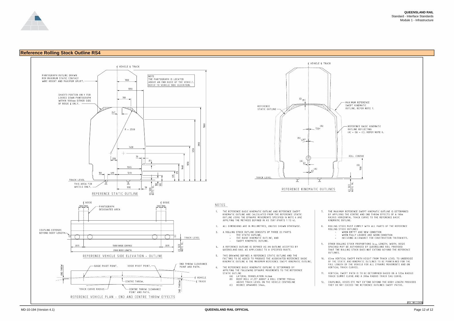
1(a) • trackside structures and rolling stock conforming to the reference vehicle QRR
1(b) • rolling stock on adjacent tracks where the rolling stock on both tracks conforms to the
reference vehicle
QRR
2 The rolling stock outlines for Queensland Rail lines are shown in Appendix 1.2 and
include both the dimensions and dynamic characteristics for standard reference
vehicles.
QRR
3 Queensland Rail Access and Business Strategy can advise which rolling stock outline
applies to a specific route. This may be one of the standard outlines in Appendix 1.2 or
an additional outline.
SUP
4 Some routes can also accept rolling stock with other dimensional or dynamic
characteristics. Queensland Rail Access and Business Strategy may approve other
vehicles subject to operating restrictions.
QRR
MD-10-194 (Version 4.1)
____________________________________________________________________________________________________________
QUEENSLAND RAIL OFFICIAL Page 3 of 12

QUEENSLAND RAIL
Standard - Interface Standards
Module 1 - Infrastructure
Clause Requirements Type
1.1.5 Axle Loads HED
1 Queensland Rail infrastructure is constructed and maintained to carry axle loads of the
train at the load / speed combination for the route specified in MD-10-533 "Operational
Route Manual" providing the axle spacing requirements in module 2 of this standard are
also met.
QRR
2 Some routes can also accept other axle load / speed combinations. Queensland Rail
Access and Business Strategy may approve other vehicles subject to operating
restrictions.
QRR
1.1.6 Rail Profiles HED
1 Rail can be the as rolled profile, the traffic worn shape or may be ground. SUP
2 Rail grinding may also be used to remove corrugations or other rail defects without
gross changes to the insitu rail shape.
SUP
3 General rail profile details can be obtained from Queensland Rail Access and Business
Strategy.
SUP
1.1.7 Rail Lubricators HED
1 Rail lubricators are placed on all balloon loops for effective lubrication. SUP
2 Rail lubricators may be placed at other locations on the Queensland Rail network where
excessive wear occurs or is likely to occur.
SUP
1.2 Electrical Traction Systems HED
1.2.1 General HED
1 Within the Queensland Rail network there are two electrically different systems used for
providing 25kV to the pantograph:
SUP
1(a) • Booster Transformer System SUP
1(b) • Auto Transformer System SUP
2 The neutral section Automatic Power Control (APC) track magnets are located between
5m to 48m from the neutral section.
QRR
3 The APC magnets are spaced from the neutral section based on a 0.5s MCB opening
time.
QRR
4 The overhead traction system is electrically connected to earth or the 25kV supply. QRR
5 The traction earthing and bonding system provides a continuous return path for traction
return currents and does not rely on signal track bonds for continuity.
QRR
1.2.2 Contact/Catenary System HED
1 Open route minimum contact wire height at supports is 4.5m QRR
2 Maximum contact wire height is 5.8m QRR
3 The total side displacement of the contact wire (including stagger, temperature effect
and wind load) under operating wind conditions is up to 510 mm.
QRR
4 The designed horizontal stagger of the contact wire is as follows: QRR
4(a) • 230mm on straights QRR
4(b) • 350mm to 380mm on curves QRR
4(c) • 400mm maximum acceptable stagger QRR
5 The contact wire tension will range between 11.0kN and 12.26kN. QRR
6 The nominal maximum train speed for which the above overhead wiring system is
designed is 160km/h.
QRR
7 The nominal maximum grading for contact wire is 1 in 480 but it may be up to 1 in 200. QRR
1.2.3 Power System Parameters HED
1 The overhead line equipment operates at 25kV, 50 Hertz, alternating supply. SUP
2 Expected 50Hz supply voltage levels and their occurrence levels are as follows: QRR
2(a) • 30kV max regularly for short duration QRR
2(b) • 27.5kV Nominal continuous maximum QRR
MD-10-194 (Version 4.1)
____________________________________________________________________________________________________________
QUEENSLAND RAIL OFFICIAL Page 4 of 12

QUEENSLAND RAIL
Standard - Interface Standards
Module 1 - Infrastructure
Clause Requirements Type
2(c) • 19kV Nominal continuous minimum QRR
2(d) • 17.5kV minimum for short duration (prolonged under unusual circumstances) QRR
3 Consideration must be given to harmonic over voltages and onerous transient voltage
disturbances, which can cause voltage disturbances exceeding 66kVpeak.
QRR
4 During normal operation the frequency of the supply may vary from 49.5Hz to 50.5Hz,
abnormal operation can produce short periods in which the frequency varies from 47Hz
to 52Hz.
QRR
5 The short circuit capacity of the overhead supply system is 12kA and the pantograph
must be suitably rated and tested to this level as a minimum.
QRR
1.3 Requirements for Mobile Voice Radio Communications Systems HED
1.3.1 Mobile Voice Radio Communications Systems HED
1 Train Control Radio (TCR) is a wide-area open-channel UHF radio system that is used
to provide two-way voice communications between trains and train control. This system
is the primary mobile voice radio communications system in the Queensland Rail
network for controlling trains.
SUP
2 Maintenance Supervisory Radio (MSR) is a wide-area open-channel UHF radio system
that is used to provide two-way voice communications during maintenance operations
(on or adjacent to the rail corridor).
SUP
3 Where the Train Control Radio (TCR) system is unavailable, the Maintenance
Supervisory Radio (MSR) system will be used to provide mobile voice radio
communications between drivers and train controllers.
SUP
1.3.2 End-User Radio Communications Equipment HED
1 All Train Control Radios (TCRs) must be compatible with Queensland Rail’s wide-area
open-channel UHF TCR system.
QRR
2 Each train must be supplied with two radios. QRR
3 Radio 1 must be dedicated to the train control channel and may be either of the
following configurations:
QRR
3(a) • 25 watt mobile radio fixed in the active driver’s cab QRR
3(b) • 25 watt transportable radio located in the active driver's cab QRR
4 Radio 2 must be compatible with local communications channels and may be any one
of the following configurations:
QRR
4(a) • 25 watt mobile radio fixed in the active driver’s cab QRR
4(b) • 25 watt transportable radio located in the active driver's cab QRR
4(c) • 4 watt hand held portable radio located in the active driver's cab for trains operating
inside Brisbane's suburban and interurban areas being all lines including branches
between Gympie North and Rosewood.
QRR
5 All mobile voice communications equipment must operate on a battery power supply. QRR
6 All Maintenance Supervisory Radios (MSRs) must be compatible with Queensland
Rail’s wide-area open-channel UHF MSR system.
QRR
1.4 Track Monitoring HED
1.4.1 Hazard Location HED
1 The rolling stock operator must advise the train controller of any track quality concerns,
indicating the hazard and location which is likely to reduce the capability of the track to
safely perform.
QRR
1.5 Level Crossing Safety HED
1.5.1 Responsibilities HED
1 Queensland Rail responsibilities at public and pedestrian level crossings are as follows: QRR
1(a) • installing and maintaining flashing lights, boom gates, bells and associated equipment
at the crossing
QRR
1(b) • erecting and maintaining all signs immediately adjacent to the tracks QRR
MD-10-194 (Version 4.1)
____________________________________________________________________________________________________________
QUEENSLAND RAIL OFFICIAL Page 5 of 12

QUEENSLAND RAIL
Standard - Interface Standards
Module 1 - Infrastructure
Clause Requirements Type
1(c) • maintaining the road pavement between the rails and for a distance of 0.6m outside
the rails
QRR
1(d) • maintaining the sight distances free of obstructing vegetation within the rail corridor QRR
1(e) • setting the maximum train speed through the crossing, in accordance with the
agreement on control measures
QRR
2 The road authority responsibilities at public and pedestrian level crossings are as
follows:
QRR
2(a) • erecting and maintaining all signs and markings on the road associated with the public
level crossing
QRR
2(b) • maintaining the road pavement exclusive of that portion maintained by Queensland
Rail
QRR
2(c) • setting the maximum road vehicle speed through the crossing, in accordance with the
agreement on control measures
QRR
3 The property owner responsibilities at private (occupation) level crossings are as
follows.
QRR
3(a) • as defined in the level crossing agreement for the operation of the crossing QRR
3(b) • where locked gates are required, keeping them locked except during use QRR
3(c) • making visitors aware of the safety aspects of using the crossing QRR
4 Queensland Rail responsibilities at private (occupation) level crossings are as follows: QRR
4(a) • maintaining all signage relating to the level crossing QRR
4(b) • maintaining the road surface of the crossing and of the roadway within Queensland
Rail property
QRR
4(c) • maintaining the sight distance free of obstructing vegetation within the rail corridor. QRR
1.5.2 Crossings used for Special Purposes HED
1 If a property owner wishes to use a private level crossing for a special purpose, such as
crossing stock, a high or wide vehicle, emergency use (eg floods), the property owner
must contact train control in order for arrangements to be organised for the special use
of the crossing.
QRR
1.5.3 Management HED
1 The management of public and pedestrian level crossings involves both state and local
road authorities and Queensland Rail.
GUI
1.6 Signalling of Trains HED
1.6.1 Train Location and Detection HED
1 There must be compatibility between trains, the track infrastructure, overhead electric
traction systems and the train location system where the location system automatically
detects the presence or absence of a train.
QRR
2 Train detection systems, eg track circuits, axle counters, and GPS, are designed to
detect the presence of a train or any other on-track vehicle, safeguarding against the
effects of train division on the Queensland Rail network.
GUI
3 Permanent and electro-magnets, where required, are located on the approach side of
the signal - generally at 0, 80 or 200m.
GUI
4 In the Brisbane Suburban Electrified Area, Automatic Warning System (AWS) magnets
are installed generally 80m on the approach side of the signal.
GUI
5 Where track magnets are provided for Station Protection (SP), they are generally
positioned 2000m from the approach side of the signal.
GUI
6 AWS and SP magnets are located along the centre line of the track. GUI
7 Automatic Power Control (APC) magnets are placed in pairs, with one pair at the
beginning and one pair at the end of neutral sections, coal loadouts and gaps in
overhead traction wiring.
GUI
8 APC track magnets are located at the ends of sleepers. GUI
9 The top of the track magnets are 25mm to 30mm below rail level. GUI
MD-10-194 (Version 4.1)
____________________________________________________________________________________________________________
QUEENSLAND RAIL OFFICIAL Page 6 of 12
QUEENSLAND RAIL
Standard - Interface Standards
Module 1 - Infrastructure
Clause Requirements Type
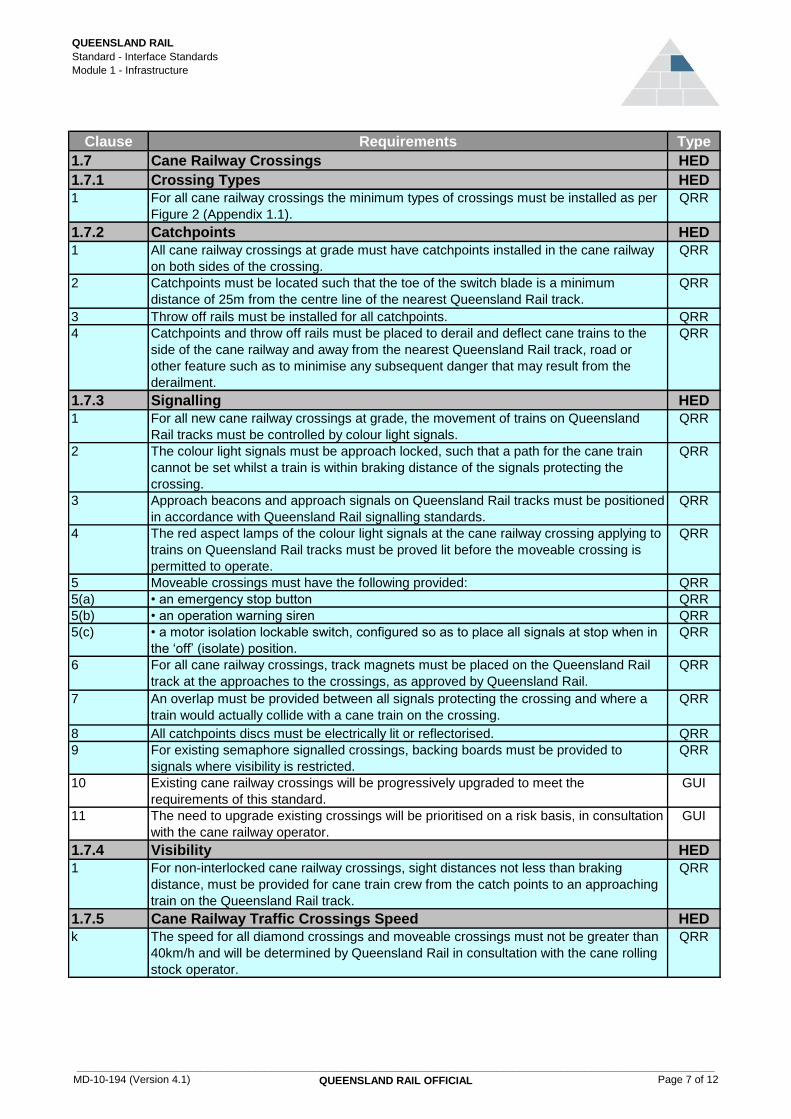
1.7 Cane Railway Crossings HED
1.7.1 Crossing Types HED
1 For all cane railway crossings the minimum types of crossings must be installed as per
Figure 2 (Appendix 1.1).
QRR
1.7.2 Catchpoints HED
1 All cane railway crossings at grade must have catchpoints installed in the cane railway
on both sides of the crossing.
QRR
2 Catchpoints must be located such that the toe of the switch blade is a minimum
distance of 25m from the centre line of the nearest Queensland Rail track.
QRR
3 Throw off rails must be installed for all catchpoints. QRR
4 Catchpoints and throw off rails must be placed to derail and deflect cane trains to the
side of the cane railway and away from the nearest Queensland Rail track, road or
other feature such as to minimise any subsequent danger that may result from the
derailment.
QRR
1.7.3 Signalling HED
1 For all new cane railway crossings at grade, the movement of trains on Queensland
Rail tracks must be controlled by colour light signals.
QRR
2 The colour light signals must be approach locked, such that a path for the cane train
cannot be set whilst a train is within braking distance of the signals protecting the
crossing.
QRR
3 Approach beacons and approach signals on Queensland Rail tracks must be positioned
in accordance with Queensland Rail signalling standards.
QRR
4 The red aspect lamps of the colour light signals at the cane railway crossing applying to
trains on Queensland Rail tracks must be proved lit before the moveable crossing is
permitted to operate.
QRR
5 Moveable crossings must have the following provided: QRR
5(a) • an emergency stop button QRR
5(b) • an operation warning siren QRR
5(c) • a motor isolation lockable switch, configured so as to place all signals at stop when in
the ‘off’ (isolate) position.
QRR
6 For all cane railway crossings, track magnets must be placed on the Queensland Rail
track at the approaches to the crossings, as approved by Queensland Rail.
QRR
7 An overlap must be provided between all signals protecting the crossing and where a
train would actually collide with a cane train on the crossing.
QRR
8 All catchpoints discs must be electrically lit or reflectorised. QRR
9 For existing semaphore signalled crossings, backing boards must be provided to
signals where visibility is restricted.
QRR
10 Existing cane railway crossings will be progressively upgraded to meet the
requirements of this standard.
GUI
11 The need to upgrade existing crossings will be prioritised on a risk basis, in consultation
with the cane railway operator.
GUI
1.7.4 Visibility HED
1 For non-interlocked cane railway crossings, sight distances not less than braking
distance, must be provided for cane train crew from the catch points to an approaching
train on the Queensland Rail track.
QRR
1.7.5 Cane Railway Traffic Crossings Speed HED
k The speed for all diamond crossings and moveable crossings must not be greater than
40km/h and will be determined by Queensland Rail in consultation with the cane rolling
stock operator.
QRR
MD-10-194 (Version 4.1)
____________________________________________________________________________________________________________
QUEENSLAND RAIL OFFICIAL Page 7 of 12

QUEENSLAND RAIL
Standard - Interface Standards
Module 1 - Infrastructure
Appendix 1.1
Top (mm)
Twist (mm)
Chord 3m
1067mm
gauge
2.7m SG
Twist
(mm)
Chord
10m
1067mm
gauge
13.2m
SG
Versine
(mm)
Cant (mm)
variation from
design
4 ±20 ±13 ±25 ±15 ±30
5 ±25 ±16 ±30 ±22 ±30
6 ±28 ±19 ±30 ±27 ±32
7 ±31 ±22 ±30 ±31 ±34
8 ±34 ±25 ±30 ±36 ±36
9 ±37 ±27 ±30 ±40 ±38
10 ±40 ±30 ±30 ±45 ±40
SG1 & 1C±19
±28±17 ±35
±17
±20±40
Main Line Crossings
Branch Line Crossings
≤80 Fabricated 60kg diamond
≤50 Fabricated 41kg diamond
100-160 Grade Separation
80-100 Moveable or manganese diamond crossing
Applicable Speed
Range (km/h)Crossing Type
Figure 2 - Cane Train Crossing Types
Figure 1 - Track Geometry Parameter Limits
Parameter Limits
Tra
ck
Cate
go
ry
MD-10-194 (Version 4.1)
____________________________________________________________________________________________________________
QUEENSLAND RAIL OFFICIAL Page 8 of 12

QUEENSLAND RAIL
Standard - Interface Standards
Module 1 - Infrastructure
Appendix 1.2
Reference Rolling Stock Outline RS1
MD-10-194 (Version 4.1) QUEENSLAND RAIL OFFICIAL Page 9 of 12

QUEENSLAND RAIL
Standard - Interface Standards
Module 1 - Infrastructure
Reference Rolling Stock Outline RS2
MD-10-194 (Version 4.1) QUEENSLAND RAIL OFFICIAL Page 10 of 12

QUEENSLAND RAIL
Standard - Interface Standards
Module 1 - Infrastructure
Reference Rolling Stock Outline RS3
MD-10-194 (Version 4.1) QUEENSLAND RAIL OFFICIAL Page 11 of 12
QUEENSLAND RAIL
Standard - Interface Standards
Module 1 - Infrastructure
Reference Rolling Stock Outline RS4
MD-10-194 (Version 4.1) QUEENSLAND RAIL OFFICIAL Page 12 of 12

Version: 4.1
Updated: 04/09/2017 Policy: Safety Policy
MD-10-194 QUEENSLAND RAIL OFFICIAL
Interface Standards Module 2 Rolling Stock

QUEENSLAND RAIL
Standard - Interface Standards
Module 2 - Rolling Stock
2 REQUIREMENTS 5
2.1 General 5
2.2 Clearances and Axle Loads 5
2.2.1 Clearances 5
2.2.2 Axle Loads / Spacing 5
2.3 Visibility and Audibility 5
2.3.1 Lighting General 5
2.3.2 Headlight 6
2.3.3 Visibility Lights 6
2.3.4 Tail Lights, Marker Lights, and Headlight Operation 6
2.3.5 Livery and Signage 6
2.3.6 Horns 7
2.3.7 On-Track Machines Additional Requirements 7
2.3.8 RRV Additional Requirements 7
2.4 Cab Layout 8
2.4.1 Driving Positions 8
2.4.2 Sighting Requirements 8
2.4.3 On-Track Machine Additional Requirements 8
2.4.4 Heritage Rolling Stock Additional Requirements 8
2.5 Structural Requirements 8
2.5.1 Structural Rating 8
2.5.2 Derailment Performance 8
2.5.3 Collision Protection 8
2.5.4 Train Obstacle Deflector (Cowcatcher) 8
2.5.5 Underframe Equipment 9
2.5.6 Fuel Tanks 9
2.5.7 Floor Height 9
2.5.8 Heritage Rolling Stock Additional Requirements 9
2.6 Pantograph Requirements 9
2.6.1 General 9
2.6.2 Characteristics 9
2.6.3 Multiple Pantographs on a Train or Vehicle 9
2.7 Drawgear 10
2.7.1 General 102.7.2 Geometric Performance 102.7.3 Crashworthiness Performance 10
2.7.4 Recovery of Failed Trains 10
2.7.5 On-Track Machine Additional Requirements 10
2.8 Axle Bearings 10
2.8.1 Hot Bearing Detection (HBD) 10
2.9 Rolling Stock Fire Performance 11
2.9.1 Rolling Stock Requirements 11
2.1 Structural Requirements for Railway Bogies 11
2.10.1 Interfaces 11
2.10.2 Heritage Rolling Stock 11
2.11 Wheel Defect Identification and Rectification 12
2.11.1 General Requirements 12
2.11.2 Wheel Flats (Skids) 12
Table of Contents
MODULE 2 - ROLLING STOCK
MD-10-194 (Version 4.1)
____________________________________________________________________________________________________________
QUEENSLAND RAIL OFFICIAL Page 2 of 42

QUEENSLAND RAIL
Standard - Interface Standards
Module 2 - Rolling Stock
2.11.3 Shelled Tread 12
2.11.4 Built Up Tread 12
2.11.5 Flange Defects 12
2.11.6 Wheel Cracks 12
2.11.7 Limiting Tread and Flange Dimensions 12
2.12 Hygiene Requirements 12
2.12.1 Waste 12
2.13 Dynamic Performance 13
2.13.1 General 13
2.13.2 Hunting (Lateral Instability) 13
2.13.3 Base Ride Accelerations 13
2.13.4 Horizontal and Vertical Curve Negotiation 13
2.13.5 Transition Curve Negotiation 14
2.13.6 Twist Test and Bogie Rotational Resistance 14
2.13.7 On Track Tests 14
2.13.8 Rollover 15
2.13.9 Negotiation of Isolated Track Irregularities 15
2.13.10 Negotiation of Cyclic Track Irregularities 15
2.13.11 Longitudinal Forces in Curves 16
2.13.12 Forces Exerted on the Track 16
2.13.13 Wind Load Considerations 16
2.13.14 RRV Additional Requirements 17
2.14 Emergency Requirements 17
2.14.1 General 17
2.14.2 On-Track Machines Additional Requirements 17
2.14.3 RRV Additional Requirements 17
2.15 Wheelsets 17
2.15.1 Design, Material and Manufacture 17
2.15.2 Tread and Flange Profile 17
2.15.3 Track Circuit Detection 18
2.15.4 On-Track Machine Additional Requirements 18
2.15.5 RRV Additional Requirements 18
2.15.6 Heritage Rolling Stock Additional Requirements 19
2.16 Brake System Requirements 19
2.16.1 General 19
2.16.2 Train Braking Performance 19
2.16.3 Vehicle Braking Performance 19
2.16.4 Brake System Energy 19
2.16.5 Brake Control System 20
2.16.6 Brake Force Application - Friction, Dynamic and Regenerative 20
2.16.7 Brake System Coupling Between Vehicles 20
2.16.8 Parking Brake 20
2.16.9 On-Track Machine Additional Requirements 21
2.16.10 RRV Additional Requirements 21
2.17 On-Track Machines - Special Requirements 22
2.17.1 Jacking and Lift Points 22
2.17.2 Maximum Rail Stress 22
2.17.3 On-Track Machines Pushed and Controlled by Workers at Walking Pace 22
2.17.4 RRVs - Special Requirements 22
2.18 Rolling Stock Electromagnetic Compatibility (EMC) 22
2.18.1 General EMC Requirements 22
2.18.2 Additional Immunity Requirements 23
2.18.3 Harmonics 23
2.18.4 Total Harmonic Distortion (THD) 23
MD-10-194 (Version 4.1)
____________________________________________________________________________________________________________
QUEENSLAND RAIL OFFICIAL Page 3 of 42

QUEENSLAND RAIL
Standard - Interface Standards
Module 2 - Rolling Stock
2.18.5 Psophometric Current 23
2.18.6 Signalling - Audio Frequency Track Circuits 23
2.18.7 Magnetic Field 23
2.18.8 Longitudinal Voltage 24
2.18.9 DC Current Limits for Signalling Track Circuits 24
2.18.10 Interference to QR UHF Radio and Other On-Board Com. Systems 24
2.19 Electrical Equipment Systems for Rolling Stock 24
2.19.1 Earthing System 24
2.19.2 Electrical Insulation System 24
2.20 Signalling of Trains 24
2.20.1 Track Circuit Detection 24
2.20.2 Axle Counter Detection 24
2.21 Train Safety Systems 24
2.21.1 Protection from Driver Incapacity 24
2.21.2 Protection from Exceeding Limit of Authority 25
2.21.3 Protection from Exceeding Speed Limit 25
2.21.4 On Track Machines 25
2.21.5 Infrastructure Based Systems 25
2.21.6 Automatic Train Protection (ATP) 25
2.21.7 Station Protection (SP) 25
2.21.8 Automatic Warning System (AWS) 25
2.21.9 Magnet Receiver 26
2.22 Powered Rolling Stock Operated By Remote Control 26
2.23 Additional Requirements - Non Standard Rolling Stock 27
Appendix 2.1 28
Appendix 2.2 40
MD-10-194 (Version 4.1)
____________________________________________________________________________________________________________
QUEENSLAND RAIL OFFICIAL Page 4 of 42
QUEENSLAND RAIL
Standard - Interface Standards
Module 2 - Rolling Stock
Clause Requirements Type
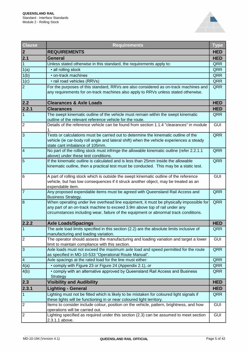
2 REQUIREMENTS HED
2.1 General HED
1 Unless stated otherwise in this standard, the requirements apply to: QRR
1(a) • all rolling stock QRR
1(b) • on-track machines QRR
1(c) • rail road vehicles (RRVs) QRR
2 For the purposes of this standard, RRVs are also considered as on-track machines and
any requirements for on-track machines also apply to RRVs unless stated otherwise.
QRR
2.2 Clearances & Axle Loads HED
2.2.1 Clearances HED
1 The swept kinematic outline of the vehicle must remain within the swept kinematic
outline of the relevant reference vehicle for the route.
QRR
2 Details of the reference vehicle can be found from section 1.1.4 "clearances" in module
1.
GUI
3 Tests or calculations must be carried out to determine the kinematic outline of the
vehicle (ie car-body roll angle and lateral shift) when the vehicle experiences a steady
state cant imbalance of 105mm.
QRR
4 No part of the rolling stock must infringe the allowable kinematic outline (refer 2.2.1.1
above) under these test conditions.
QRR
5 If the kinematic outline is calculated and is less than 25mm inside the allowable
kinematic outline, then a practical test must be conducted. This may be a static test.
QRR
6 A part of rolling stock which is outside the swept kinematic outline of the reference
vehicle, but has low consequences if it struck another object, may be treated as an
expendable item.
GUI
7 Any proposed expendable items must be agreed with Queensland Rail Access and
Business Strategy.
QRR
8 When operating under live overhead line equipment, it must be physically impossible for
any part of an on-track machine to exceed 3.9m above top of rail under any
circumstances including wear, failure of the equipment or abnormal track conditions.
QRR
2.2.2 Axle Loads/Spacings HED
1 The axle load limits specified in this section (2.2) are the absolute limits inclusive of
manufacturing and loading variation.
QRR
2 The operator should assess the manufacturing and loading variation and target a lower
limit to maintain compliance with this section.
GUI
3 Axle loads must not exceed the maximum axle load and speed permitted for the route
as specified in MD-10-533 "Operational Route Manual".
QRR
4 Axle spacings at the rated load for the line must either: QRR
4(a) • comply with Figure 23 or Figure 24 (Appendix 2.1), or QRR
4(b) • comply with an alternative approved by Queensland Rail Access and Business
Strategy
QRR
2.3 Visibility and Audibility HED
2.3.1 Lighting - General HED
1 Lighting must not be fitted which is likely to be mistaken for coloured light signals if
these lights will be functioning in or near coloured light territory.
QRR
2 Items to consider include colour, position on the vehicle, pattern, brightness, and how
operations will be carried out.
GUI
2 Lighting specified as required under this section (2.3) can be assumed to meet section
2.3.1.1 above.
GUI
MD-10-194 (Version 4.1)
____________________________________________________________________________________________________________
QUEENSLAND RAIL OFFICIAL Page 5 of 42

QUEENSLAND RAIL
Standard - Interface Standards
Module 2 - Rolling Stock
Clause Requirements Type
2.3.2 Headlight HED
1 Rolling stock which can be the leading end of a train in normal operation (excludes
setting back and propelling) must have a white headlight fitted at any leading end.
QRR
2 The headlight may be a single lamp, two or more lamps in a single assembly, or two or
more lamps in separate assemblies.
QRR
3 Headlight arrangements must produce a peak intensity of at least 200,000 candela. QRR
4 "Headlight arrangements" is the total of all operating headlamps. QRR
5 The peak intensity requirement must also be met if devices to protect / diffuse the
headlamps are fitted while in service.
QRR
6 Headlights must be at least 2.3m above rail. QRR
7 The centreline of each headlamp beam must be aimed at a point 240m in front of the
vehicle at top of track.
QRR
8 Headlights must have the ability to be dimmed. QRR
2.3.3 Visibility Lights HED
1 Rolling stock must have a minimum of two white visibility lights fitted at any end which
can be the leading end of a train in normal operation (excluding setting back and
propelling).
QRR
2 Each visibility light must produce a peak intensity of at least 20,000 candela. QRR
3 Visibility lights must be: QRR
3(a) • at least 600mm above the top of the rail QRR
3(b) • laterally separated by at least 900mm if they are mounted 1500mm or more below
the headlights
QRR
3(c) • laterally separated by at least 1500mm if they are mounted less than 1500mm below
the headlights
QRR
4 Visibility lights must be aimed at a point that is at least 25m in front of the vehicle at top
of track.
QRR
5 Visibility lights must then be aimed / turned cross-eyed to between a minimum of 7.5
degrees and a maximum of 15 degrees to the longitudinal centreline of the vehicle.
QRR
2.3.4 Tail Lights, Marker Lights, and Headlight Operation HED
1 Locomotives, self propelled passenger vehicles (including trailer units of a permanently
coupled self propelled consist), and other self propelled rolling stock must have red tail
and white marker lights fitted as high and wide as practical at both sides of each end
which can be the end of a train.
QRR
2 Train direction-of-travel and completeness must be shown by: QRR
2(a) • headlights or white marker lights at the leading end of a train, and QRR
2(b) • at least one functioning red tail light or an approved end-of-train marker, at rear of
the last vehicle
QRR
3 Marker lights and tail lights must be: QRR
3(a) • (where fitted) lit during travel, and QRR
3(b) • if defective, repaired or replaced as soon as possible. QRR
4 End of train markers QRR
4(a) • may travel without being lit during hours of good visibility QRR
4(b) • must be lit during hours of poor visibility QRR
2.3.5 Livery and Signage HED
1 Rolling stock must have livery applied that enhances the visibility of the vehicle. QRR
2 Any end of rolling stock which can be the leading end of a train in normal operation
must have a forward facing area of high visibility colour not less than 1m² in area with a
minimum continuous height or width of 0.6m.
QRR
MD-10-194 (Version 4.1)
____________________________________________________________________________________________________________
QUEENSLAND RAIL OFFICIAL Page 6 of 42

QUEENSLAND RAIL
Standard - Interface Standards
Module 2 - Rolling Stock
Clause Requirements Type
3 The high visibility colour may be yellow or orange or white. QRR
4 The forward facing area of high visibility colour may be divided by the features of the
front of the rolling stock if necessary.
QRR
5 Each section of a divided high visibility colour surface must have an uninterrupted area
of 0.4m² with a minimum continuous height or width of 0.6m.
QRR
6 If the front of the rolling stock slopes from vertical or is rounded, the area of the high
visibility colour surface and its vertical and/or horizontal dimensions must be increased
in order to produce the equivalent required areas and dimensions when projected onto
a vertical plane.
QRR
7 As the application of large areas of high visibility colour may generally not be in keeping
with the nature of heritage rolling stock, the rolling stock operator may propose
alternative control mechanisms that will:
QRR
7(a) • enhance the visibility, or QRR
7(b) • demonstrate, through the risk management process, that the visibility hazard is
acceptably controlled
QRR
8 Reflective decal(s) of minimum total area 0.05m² must be fitted to each side of all
rolling stock. Class 1A reflective material compliant with AS/NZS 1906.1 must be
used.
QRR
2.3.6 Horns HED
1 Rolling stock which can be the leading end of a train in normal operation must have a
warning horn fitted which is capable of providing a minimum sound pressure level of
96dBA measured (with the vehicle stationary) 30m in front of the vehicle, 1.5m above
track centreline on level, straight track in open surroundings.
QRR
2.3.7 On-Track Machines Additional Requirements HED
1 Exterior lighting must be unobstructed from view. QRR
2 Where travel lights of the towing vehicle are obscured by the trailer or load then these
must be duplicated on the rear of the trailer.
QRR
3 To protect personnel who may work on the ground in the vicinity, all on-track machines
must be fitted with a warning beeper that sounds when a change of direction is made in
work mode.
QRR
4 Amber flashing beacon(s) may be fitted to the vehicle. QRR
5 The beacons, if fitted, must flash at between 1Hz and 3Hz. QRR
6 On-track machines that travel at speeds not exceeding 60km/h and are less than 20
tonne gross mass must comply with the above requirements except as follows:
QRR
6(a) • May have a single headlight of at least 100,000 candela, providing the visibility
light(s) is also at least 100,000 candela
QRR
6(b) • In the case of a single headlight and single visibility light, must have the lights
mounted as close as practical to the vertical centreline of the machine with the
headlight as high as possible and at least 1500mm above the visibility light
QRR
6(c) • Lighting is not required for on-track machine trailer vehicles, that are less than 20
tonnes gross mass and can be towed at speeds not exceeding 60km/h, unless they
are required for work purposes
QRR
6(d) • Must have a horn that provides at least 82dBA at 30m QRR
2.3.8 RRV Additional Requirements HED
1 Marker lights and visibility lights must, as far as reasonably practicable, meet the
standard lighting requirements in section 2.3
QRR
2 RRVs may be predominantly white. GUI
MD-10-194 (Version 4.1)
____________________________________________________________________________________________________________
QUEENSLAND RAIL OFFICIAL Page 7 of 42
QUEENSLAND RAIL
Standard - Interface Standards
Module 2 - Rolling Stock
Clause Requirements Type
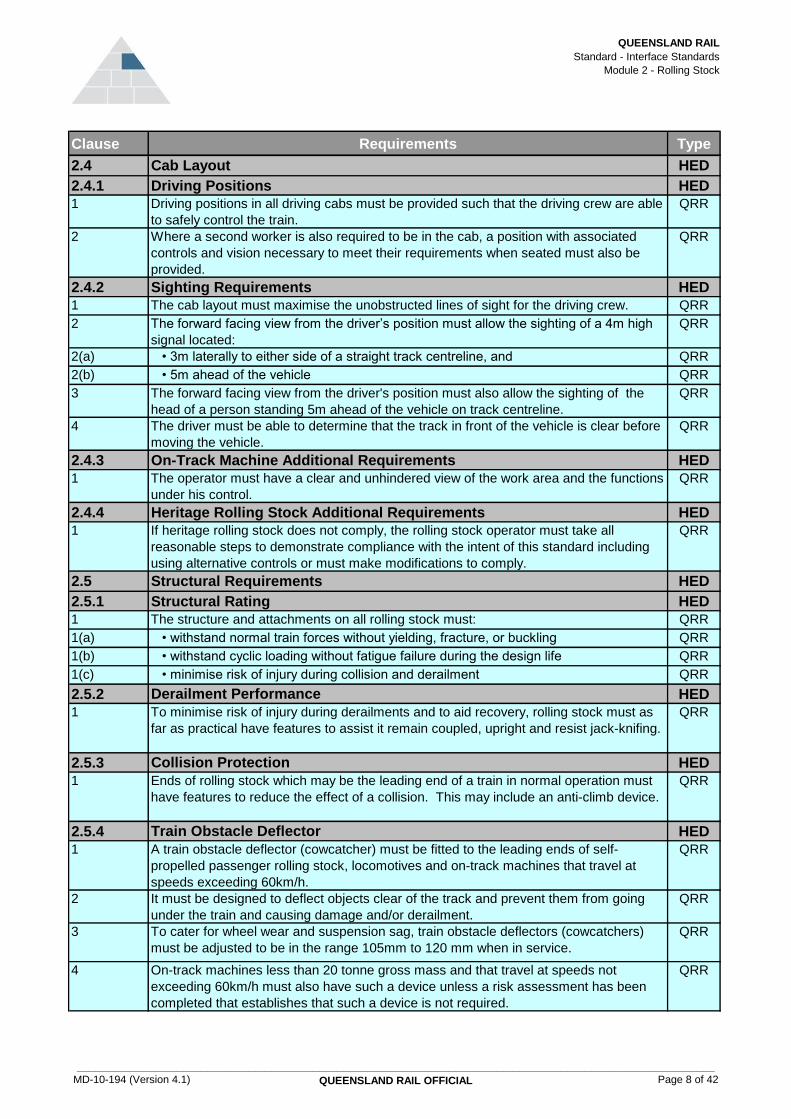
2.4 Cab Layout HED
2.4.1 Driving Positions HED
1 Driving positions in all driving cabs must be provided such that the driving crew are able
to safely control the train.
QRR
2 Where a second worker is also required to be in the cab, a position with associated
controls and vision necessary to meet their requirements when seated must also be
provided.
QRR
2.4.2 Sighting Requirements HED
1 The cab layout must maximise the unobstructed lines of sight for the driving crew. QRR
2 The forward facing view from the driver’s position must allow the sighting of a 4m high
signal located:
QRR
2(a) • 3m laterally to either side of a straight track centreline, and QRR
2(b) • 5m ahead of the vehicle QRR
3 The forward facing view from the driver's position must also allow the sighting of the
head of a person standing 5m ahead of the vehicle on track centreline.
QRR
4 The driver must be able to determine that the track in front of the vehicle is clear before
moving the vehicle.
QRR
2.4.3 On-Track Machine Additional Requirements HED
1 The operator must have a clear and unhindered view of the work area and the functions
under his control.
QRR
2.4.4 Heritage Rolling Stock Additional Requirements HED
1 If heritage rolling stock does not comply, the rolling stock operator must take all
reasonable steps to demonstrate compliance with the intent of this standard including
using alternative controls or must make modifications to comply.
QRR
2.5 Structural Requirements HED
2.5.1 Structural Rating HED
1 The structure and attachments on all rolling stock must: QRR
1(a) • withstand normal train forces without yielding, fracture, or buckling QRR
1(b) • withstand cyclic loading without fatigue failure during the design life QRR
1(c) • minimise risk of injury during collision and derailment QRR
2.5.2 Derailment Performance HED
1 To minimise risk of injury during derailments and to aid recovery, rolling stock must as
far as practical have features to assist it remain coupled, upright and resist jack-knifing.
QRR
2.5.3 Collision Protection HED
1 Ends of rolling stock which may be the leading end of a train in normal operation must
have features to reduce the effect of a collision. This may include an anti-climb device.
QRR
2.5.4 Train Obstacle Deflector HED
1 A train obstacle deflector (cowcatcher) must be fitted to the leading ends of self-
propelled passenger rolling stock, locomotives and on-track machines that travel at
speeds exceeding 60km/h.
QRR
2 It must be designed to deflect objects clear of the track and prevent them from going
under the train and causing damage and/or derailment.
QRR
3 To cater for wheel wear and suspension sag, train obstacle deflectors (cowcatchers)
must be adjusted to be in the range 105mm to 120 mm when in service.
QRR
4 On-track machines less than 20 tonne gross mass and that travel at speeds not
exceeding 60km/h must also have such a device unless a risk assessment has been
completed that establishes that such a device is not required.
QRR
MD-10-194 (Version 4.1)
____________________________________________________________________________________________________________
QUEENSLAND RAIL OFFICIAL Page 8 of 42

QUEENSLAND RAIL
Standard - Interface Standards
Module 2 - Rolling Stock
Clause Requirements Type
2.5.5 Underframe Equipment HED
1 Underframe mounted equipment must be either robustly constructed or suitably
protected to minimise damage from derailments, objects on the track and side impacts.
QRR
2 Support of underframe mounted equipment must be designed and maintained to
prevent the equipment from falling onto the track.
QRR
2.5.6 Fuel Tanks HED
1 Fuel tanks mounted beneath the underframe must be designed to have structural and
puncture resistance properties to minimise the risk of fuel spillage as a result of
derailments and collisions with objects on the track.
QRR
2 The filler and vent assembly must be designed to limit fuel spillage in the event of the
vehicle rolling over.
QRR
2.5.7 Floor Height HED
1 Rolling stock which will use Queensland Rail platforms for entry or exit must be
compatible with the platforms to be used or use alterative safe methods.
QRR
2 Platform dimensions are available from Queensland Rail Access and Business
Strategy.
GUI
2.5.8 Heritage Rolling Stock Additional Requirements HED
1 If heritage rolling stock does not comply, the rolling stock operator must take all
reasonable steps to demonstrate compliance with the principles and intent of this
standard including using alternative controls or must make modifications to comply.
QRR
2.6 Pantograph Requirements HED
2.6.1 General HED
1 The pantograph must be compatible with the contact wire system and be capable of
withstanding the effects of transient and short circuit currents specified in module 1
section 1.2.
QRR
2 All pantographs must conform to the requirements of CEI/IEC 60494-1 First Edition
2002-11 Railway Applications - Rolling Stock - Pantographs - Characteristics and Tests -
Part 1 Pantographs for Mainline Vehicles, International Electrotechnical Commission,
Switzerland.
QRR
3 The pantograph design must provide sparkless operation for the range of speeds from
0km/h to the maximum speed for which the rolling stock is designed to operate in both
forward and reverse direction, under normal operating conditions.
QRR
4 The pantograph design must optimise the wear in the contact wire and the current
collector of the pantograph.
QRR
5 The pantograph design must minimise the damage to the overhead wiring system and
the pantograph in the event of an incident.
QRR
6 It is assumed the insulators are included as a part of the pantograph. GUI
2.6.2 Characteristics HED
1 The pantograph tuned force must be within the range 80N +/- 10N over the minimum to
maximum static wire heights in module 1.
QRR
2 The pantograph must maintain this force over the working range on this overhead
system including allowing for uplift and dynamic effects of the vehicle.
QRR
3 In the folded position the pantograph must comply with the rolling stock outline
appropriate to the Queensland Rail track it will be operating on.
QRR
2.6.3 Multiple Pantographs on a Train or Vehicle HED
1 The distance between pantographs in a train must not be less than 20m. QRR
2 For a pantograph force of 80N ±10N and one pantograph operated on each locomotive
or multiple unit; up to three locomotives or multiple units may be coupled together
subject to meeting the minimum distance between pantographs.
QRR
MD-10-194 (Version 4.1)
____________________________________________________________________________________________________________
QUEENSLAND RAIL OFFICIAL Page 9 of 42

QUEENSLAND RAIL
Standard - Interface Standards
Module 2 - Rolling Stock
Clause Requirements Type
2.7 Drawgear HED
2.7.1 General HED
1 All rolling stock that requires to be coupled and uncoupled from other rolling stock
during normal operation must have a drawgear system fitted to each end that is suitable
for the loads and application and is compatible with other rolling stock it couples to.
QRR
2 Either: QRR
2(a) • coupler heights must be within the range 710mm to 860mm under all service
conditions; or
QRR
2(b) • the rolling stock must only be assembled in a train such that there is method for
another locomotive to couple to the train from either end if the train has failed on a
section
QRR
2.7.2 Geometric Performance HED
1 Any coupling system used must engage positively with the coupling system of any
rolling stock to which it is intended to operate and couple with, on all track features.
QRR
2 Couplers must not uncouple under anticipated service conditions unless the uncoupling
mechanism is manually actuated.
QRR
3 It must be possible to determine visually on automatic couplers whether the
mechanisms are locked on the mating couplers or not.
QRR
2.7.3 Crashworthiness Performance HED
1 For all rolling stock, during a collision or derailment, the coupling system and its
attachment to the rolling stock structure, must be designed to provide restraint that will
resist:
QRR
1(a) • adjacent coupled rolling stock moving significantly out of line QRR
1(b) • the uncoupling and over-riding of adjacent coupled rolling stock QRR
1(c) • overturning QRR
2.7.4 Recovery of Failed Trains HED
1 All rolling stock ends that may be required to be coupled to, for the recovery of failed
rolling stock, must have a coupling system that enables safe recovery to be undertaken.
QRR
2 For automatic couplers, it must be possible to arrange manual uncoupling of two items
of rolling stock if the systems normally required for this operation are unavailable.
QRR
2.7.5 On-Track Machine Additional Requirements HED
1 On-track machines designed to tow or be towed by another on-track machine must be
fitted with drawgear complying with section 2.7.1 to 2.7.3, except as follows:
QRR
1(a) • couplers must be mounted at a suitable height for towing and recovery QRR
1(b) • all tow hitches and couplings, including backup coupling devices, must have a
positive locking mechanism together with means of automatically retaining this
mechanism in the locked position
QRR
1(c) • a backup coupling device must be provided between on-track machines designed to
tow or be towed that do not have a brake that automatically applies if they part during
travel.
QRR
2.8 Axles Bearings HED
2.8.1 Hot Bearing Detection (HBD) HED
1 Unless hot bearing detection equipment is fitted to the rolling stock, the bearings must
be outside the wheels.
QRR
MD-10-194 (Version 4.1)
____________________________________________________________________________________________________________
QUEENSLAND RAIL OFFICIAL Page 10 of 42

QUEENSLAND RAIL
Standard - Interface Standards
Module 2 - Rolling Stock
Clause Requirements Type
2 When operating on routes with wayside infra-red HBD, axleboxes, full bore adaptors
and any adjacent equipment must not obscure the line of sight between the HBD
equipment and the HBD target area on the axlebox as defined for inboard scan as
detailed in AREMA C&S Manual Part 5.1.30.
QRR
3 For rolling stock that does not have hot bearing detection, the operator must have in
place procedures to inspect bearings, while travelling.
QRR
2.9 Rolling Stock Fire Performance HED
2.9.1 Rolling Stock Requirements HED
1 Rolling stock must be designed, constructed, maintained and operated so as to
minimise the risk of fire to other operators and the network.
QRR
2 The fire protection must aim to achieve the following goals: QRR
2(a) • prevent fire occurring in the first place QRR
2(b) • if a fire does happen then suppress, retard and contain it’s growth and spread in
order to minimise it’s impact to persons and assets
QRR
2(c) • protect workers and passengers from the effects of fire QRR
2(d) • assist workers and emergency service operations QRR
3 For new rolling stock, a risk analysis must be performed early in the design phase to
identify all potential fire hazards and their consequences.
QRR
4 New vehicles must be designed such that spark emissions are minimised under all load
and speed conditions.
QRR
5 All existing vehicles must be monitored on an on-going basis and maintained to a
standard to minimise spark emissions under all load and speed conditions.
QRR
6 Where spark emissions are occurring: QRR
6(a) • systems must be developed and implemented to effectively manage these
occurrences in both the short and the long term, and
QRR
6(b) • appropriate modifications must be made to minimise the incidence of spark
emission.
QRR
2.10 Structural Requirements for Railway Bogies HED
2.10.1 Interfaces HED
1 To allow for lifting of the vehicle without detachment in the event of a collision or
derailment:
QRR
1(a) • the wheelsets must be suitably restrained within the bogie QRR
1(b) • the bogie must be suitably attached to the structure of the vehicle body QRR
1(c) • on rolling stock that does not feature bogies, the wheel or wheelset must be suitably
restrained to remain attached to the vehicle during travel, work and derailments
QRR
2 The geometry of the bogie and associated components and their interaction with the
vehicle structure needs to be considered to allow for the full dynamic envelopes to be
encountered in service.
QRR
2.10.2 Heritage Rolling Stock HED
1 If a heritage vehicle does not comply, the rolling stock operator must take all reasonable
steps to demonstrate compliance with the principles and intent of this standard
including using alternative controls or must make modifications to comply.
QRR
MD-10-194 (Version 4.1)
____________________________________________________________________________________________________________
QUEENSLAND RAIL OFFICIAL Page 11 of 42
QUEENSLAND RAIL
Standard - Interface Standards
Module 2 - Rolling Stock
Clause Requirements Type
2.11 Wheel Defect Identification and Rectification HED
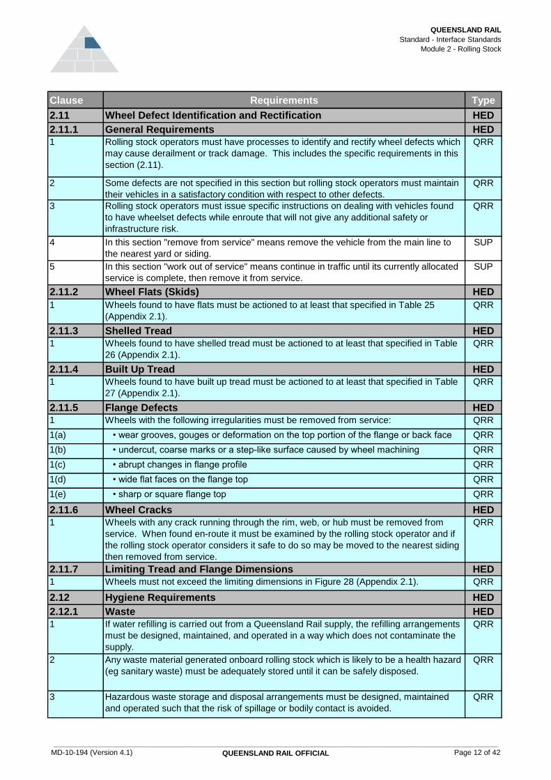
2.11.1 General Requirements HED
1 Rolling stock operators must have processes to identify and rectify wheel defects which
may cause derailment or track damage. This includes the specific requirements in this
section (2.11).
QRR
2 Some defects are not specified in this section but rolling stock operators must maintain
their vehicles in a satisfactory condition with respect to other defects.
QRR
3 Rolling stock operators must issue specific instructions on dealing with vehicles found
to have wheelset defects while enroute that will not give any additional safety or
infrastructure risk.
QRR
4 In this section "remove from service" means remove the vehicle from the main line to
the nearest yard or siding.
SUP
5 In this section "work out of service" means continue in traffic until its currently allocated
service is complete, then remove it from service.
SUP
2.11.2 Wheel Flats (Skids) HED
1 Wheels found to have flats must be actioned to at least that specified in Table 25
(Appendix 2.1).
QRR
2.11.3 Shelled Tread HED
1 Wheels found to have shelled tread must be actioned to at least that specified in Table
26 (Appendix 2.1).
QRR
2.11.4 Built Up Tread HED
1 Wheels found to have built up tread must be actioned to at least that specified in Table
27 (Appendix 2.1).
QRR
2.11.5 Flange Defects HED
1 Wheels with the following irregularities must be removed from service: QRR
1(a) • wear grooves, gouges or deformation on the top portion of the flange or back face QRR
1(b) • undercut, coarse marks or a step-like surface caused by wheel machining QRR
1(c) • abrupt changes in flange profile QRR
1(d) • wide flat faces on the flange top QRR
1(e) • sharp or square flange top QRR
2.11.6 Wheel Cracks HED
1 Wheels with any crack running through the rim, web, or hub must be removed from
service. When found en-route it must be examined by the rolling stock operator and if
the rolling stock operator considers it safe to do so may be moved to the nearest siding
then removed from service.
QRR
2.11.7 Limiting Tread and Flange Dimensions HED
1 Wheels must not exceed the limiting dimensions in Figure 28 (Appendix 2.1). QRR
2.12 Hygiene Requirements HED
2.12.1 Waste HED
1 If water refilling is carried out from a Queensland Rail supply, the refilling arrangements
must be designed, maintained, and operated in a way which does not contaminate the
supply.
QRR
2 Any waste material generated onboard rolling stock which is likely to be a health hazard
(eg sanitary waste) must be adequately stored until it can be safely disposed.
QRR
3 Hazardous waste storage and disposal arrangements must be designed, maintained
and operated such that the risk of spillage or bodily contact is avoided.
QRR
MD-10-194 (Version 4.1)
____________________________________________________________________________________________________________
QUEENSLAND RAIL OFFICIAL Page 12 of 42

QUEENSLAND RAIL
Standard - Interface Standards
Module 2 - Rolling Stock
Clause Requirements Type
4 Waste decanting fittings must be compatible with the trackside decanting equipment QRR
5 Appropriate signage to AS 1319 must be placed on any hazardous waste outlet. QRR
2.13 Dynamic Performance HED
2.13.1 General HED
1 New rolling stock, modified rolling stock, and existing rolling stock which is not currently
operating on Queensland Rail tracks must be evaluated to determine that the dynamic
performance requirements will be met for that rolling stock class.
QRR
2 While existing vehicles which are currently operating on Queensland Rail tracks need
not be evaluated this must be done for additional vehicles to be added to that class.
QRR
3 The evaluation for a class may be used for all vehicles in that class or a similar class
providing the variation within the class or classes will have no appreciable detrimental
effect on meeting dynamic performance requirements.
QRR
4 Unless specified otherwise in this section, evaluation may be by on track testing, static
tests, computer simulation, or calculation as necessary to determine that the
requirements will be met.
QRR
5 Evaluation by calculation or computer simulation must have sufficient static or dynamic
tests to validate the methods used.
QRR
6 Rolling stock must be evaluated for: QRR
6(a) • hunting as per section 2.13.2 QRR
6(b) • horizontal and vertical curve negotiation as per section 2.13.4 QRR
6(c) • transition curve negotiation as per section 2.13.5 QRR
6(d) • rollover as per section 2.13.8 QRR
6(e) • negotiation of isolated track irregularities as per section 2.13.9 QRR
6(f) • negotiation of cyclic track irregularities as per section 2.13.10 QRR
6(g) • longitudinal forces in curves as per section 2.13.11 QRR
2.13.2 Hunting (Lateral Instability) HED
1 Rolling stock must meet the requirements of AS 7509 Parts 1 to 4 (as applicable to the
rolling stock type) Section 3 with respect to hunting with the following qualifications:
QRR
1(a) • track condition for testing will be advised by Queensland Rail Access and Business
Strategy
QRR
1(b) • dry rail QRR
1(c) • AS 7508 worn wheel test profile to be used when effective concentricity is controlled
to a tighter limit than specified in these interface standards
QRR
1(d) • wheels with the applied profile worn to the highest concentricity that is likely to be
experienced may be used
QRR
2 Rolling stock which is less than 20 gross tonnes and does not exceed 40km/h is
exempt from the requirements in this section (2.13.2).
QRR
2.13.3 Base Ride Accelerations HED
1 Rolling stock should be evaluated for whether the vehicle will ride satisfactorily over
track at the lower end of the quality likely to be encountered in service.
GUI
2 Issues regarding track quality should be addressed in the Interface Risk Management
Plan.
GUI
2.13.4 Horizontal and Vertical Curve Negotiation HED
1 Rolling stock must be able to negotiate horizontal and vertical curves according to AS
7509 parts 1 to 4 (as applicable to the rolling stock type) section 5 for the curves on its
intended route.
QRR
MD-10-194 (Version 4.1)
____________________________________________________________________________________________________________
QUEENSLAND RAIL OFFICIAL Page 13 of 42

QUEENSLAND RAIL
Standard - Interface Standards
Module 2 - Rolling Stock
Clause Requirements Type
2 Rolling stock assembled in its intended train configuration must be able to negotiate
horizontal and vertical curves according to AS 7509 parts 1 to 4 (as applicable to the
rolling stock type) section 5 for the curves on its intended route.
QRR
3 Queensland Rail Access and Business Strategy is able to advise details of curves on
the route.
GUI
2.13.5 Transition Curve Negotiation HED
1 Ability of the rolling stock to safely exit a curve transition must be assessed by either: QRR
1(a) • static twist test and bogie rotational resistance in accordance with sections 2.13.6, or QRR
1(b) • on track measurement of wheel L/V and axle L/V ratios as per section 2.13.7 QRR
2.13.6 Twist Test and Bogie Rotational Resistance HED
1 If transition curve negotiation is assessed by static testing it must meet the
requirements of this section.
QRR
2 The static twist test must be carried out in accordance with Section 6.3 and 6.4 of AS
7509 Parts 1 to 4 (as applicable to the rolling stock type) with the following
qualifications:
QRR
2(a) • limiting track twist in accordance with Figures 1 and 2 (Appendix 2.1) QRR
2(b) • friction in suspension to be relieved prior to each test QRR
2(c) • the test must be repeated by jacking the same wheelsets but on the other side of the
car to check that there is no significant twist in the car body or bogies
QRR
2(d) • if an active vertical suspension is used (eg air bag secondary springs), the tests
must be repeated without power to this suspension
QRR
2(e) • all dampers, bump stops and lifting devices must be in position and correctly
adjusted during the tests
QRR
3 Articulated rolling stock, rolling stock with more than 2 bogies, rigidly coupled rolling
stock and rolling stock with varying wheel diameters must be tested as follows:
QRR
3(a) • the leading wheel-set of each bogie or group wheels of equal loading is placed at
point A in Figure 1 (Appendix 2.1).
QRR
3(b) • the direction of travel must be taken as down the ramp QRR
3(c) • non-symmetrical rolling stock, capable of travelling in both directions must be tested
in both directions
QRR
3(d) • the trailing bogie need not be tested QRR
4 Transition curve negotiation under these tests must meet the following: QRR
4(a) • the calculated bogie X-factor must be less than 0.1, and QRR
4(b) • the wheel unloading in a static twist test must be less than 60%. QRR
5 The bogie X-factor must be calculated as X = T/ (WxA) where: QRR
5(a) • T = Torque required to rotate bogie relative to body to the angle required to
negotiate the minimum radius curve
QRR
5(b) • W = Average axle load of bogie QRR
5(c) • A = Bogie wheelbase QRR
6 Steam locomotives are required to pass the wheel unloading static twist test portion of
this section. However, the calculated X-factor of this section is not applicable to steam
locomotives.
QRR
2.13.7 On Track Tests HED
1 If transition curve negotiation is by on track tests it must meet the requirements of this
section.
QRR
2 The on track test must be carried out in accordance with Section 6.5 of AS 7509 Parts 1
to 4 as relevant for the vehicle type with the following qualifications:
QRR
MD-10-194 (Version 4.1)
____________________________________________________________________________________________________________
QUEENSLAND RAIL OFFICIAL Page 14 of 42

QUEENSLAND RAIL
Standard - Interface Standards
Module 2 - Rolling Stock
Clause Requirements Type
3 During negotiation of a transition into or out of a curve the following criteria must not be
exceeded for a distance of greater than 2m (measured with an instrumented wheelset):
QRR
3(a) • maximum wheel unloading: 90% QRR
3(b) • maximum wheel L/V: 1 QRR
3(c) • maximum sum L/V axle: 1.5 QRR
4 The limiting values of track twist are as shown in Figures 1 and 2 (Appendix 2.1). QRR
5 For all twist cases, height H at point B in Figure 1 (Appendix 2.1) is calculated as H = D
+ 3000/N (mm)
QRR
2.13.8 Rollover HED
1 During curve negotiation, at the maximum cant deficiency, the minimum wheel load on
the low rail must not fall below:
QRR
1(a) • 40% of the static wheel load on average, or QRR
1(b) • 20% instantaneously during transient reactions to track irregularities QRR
2 For rolling stock that will operate at no greater than 55mm cant deficiency, calculations
may be used to verify this requirement.
QRR
2.13.9 Negotiation of Isolated Track Irregularities HED
1 Rolling stock must be capable of negotiating isolated track irregularities of the limits
given in Figure 6 (Appendix 2.1) for greater than 50 milliseconds:
QRR
1(a) • maximum wheel unloading 90%, and QRR
1(b) • maximum sum L/V axle 1.5 QRR
2 The maximum speed for testing must be, the lesser of, either: QRR
2(a) • 110% of the rolling stock design speed, or QRR
2(b) • 110% of the track speed limit applicable to irregularities of that magnitude QRR
3 Alternatively, if an instrumented wheel-set is not available then the wheel unloading limit
above is only applicable when the lateral acceleration of the car body in the same time
period is less than 0.3g.
QRR
4 When the lateral acceleration exceeds 0.3g, the wheel unloading must not exceed 60%
for greater than 50 milliseconds.
QRR
2.13.10 Negotiation of Cyclic Track Irregularities HED
1 Damping of the suspension must be sufficient so that the wheel unloading values
specified in section 2.13.9 "Negotiation of Isolated Track Irregularities" are not
exceeded for the following track conditions:
QRR
1(a) • cyclic top irregularities spaced at the bogie centre distance on each rail. The series
of irregularities on one rail are to be half the bogie centre distance out of phase with
the other rail.
QRR
1(b) • the irregularities must be of a magnitude as specified in Figure 6 (Appendix 2.1)
when loaded. All the irregularities must be of the same sign (all dips or humps)
QRR
1(c) • any speed up to and including 80km/h or the maximum speed of the rolling stock
whichever is the lower.
QRR
2 Damping of the suspension, only to rolling stock capable of 80km/h or more, must be
sufficient so that the wheel unloading values specified in section 2.13.9 "Negotiation of
Isolated Track Irregularities" are not exceeded for the following track conditions:
QRR
2(a) • approximately sinusoidal varying cant imbalance of 160mm peak to peak with a
wavelength of 50m for one cycle
QRR
2(b) • any speed from 80km/h to 110% of the rolling stock maximum design speed QRR
MD-10-194 (Version 4.1)
____________________________________________________________________________________________________________
QUEENSLAND RAIL OFFICIAL Page 15 of 42

QUEENSLAND RAIL
Standard - Interface Standards
Module 2 - Rolling Stock
Clause Requirements Type
2.13.11 Longitudinal Forces in Curves HED
1 Rolling stock when assembled in its train configurations must meet the requirements of
AS 7509 parts 1 to 4 (as applicable to the rolling stock type) section 10 for its route.
QRR
2.13.12 Forces Exerted on the Track HED
1 The wheel to rail forces exerted by rolling stock, at any time during normal operations,
must be less than the following limits:
QRR
1(a) • the maximum lateral wheel/rail force (L) must not exceed 50kN. This force limit must
apply to the maximum lateral force exerted on either rail by any wheel and is the
maximum sustained force acting over the time interval taken for the rolling stock to
travel 2m
QRR
1(b) • the maximum lateral track shifting force (S) on concrete sleepers must not exceed
0.85x(10 + P/3) kN, where P is the static axle load in kN. This force limit must apply to
the resultant lateral force exerted on both rails by any axle of the rolling stock. It must
be defined as the maximum sustained force acting over the time interval taken for the
rolling stock to travel 2m.
QRR
2 The Dynamic P2 force must be calculated using the formula in Figure 3 (Appendix 2.1). QRR
3 The P2 force is to be calculated at its nominal maximum speed and nominal gross
mass of the vehicle.
QRR
4 The values of Kt, Mt and Ct are shown in Figure 4 (Appendix 2.1). QRR
5 The values for total joint angle and limiting P2 force are listed in Figure 5 (Appendix
2.1).
QRR
6 When the effective unsprung mass of the rolling stock can be calculated readily and the
P2 force calculated is less than 180kN, physical confirmation measurements are not
mandatory.
QRR
7 Rolling stock which has axle loads under 5 tonne and does not exceed 60km/h need
not be measured for P2 force criteria.
QRR
8 For steam locomotives, and other vehicles having a connecting rod directly coupled to a
crankpin on a wheelset:
QRR
8(a) • the dynamic force exerted on the track in the vertical direction (hammer blow) by any
wheels due to residual imbalance must not be greater than the limit calculated by the
following formula, unless otherwise approved by Queensland Rail Access and
Business Strategy
8(b) • permissible imbalance force per wheel (N) = 1.4 x (speed in km/h)² but not more
than 14kN
QRR
9 Refer to AS 7508 Appendix B for guidance on how to calculate the effective unsprung
mass of the wheel(set).
GUI
2.13.13 Wind Load Considerations HED
1 Rolling stock susceptible to overturning in high winds should undergo wind loading
assessment.
GUI
2 When or where the wind speeds predicted for vehicle overturning are likely to occur
then operational controls (eg reduced overspeed, or cease operation) may be
necessary.
GUI
3 Rolling stock operators must develop and comply with controls for preventing
susceptible rolling stock overturning in high wind speeds.
QRR
MD-10-194 (Version 4.1)
____________________________________________________________________________________________________________
QUEENSLAND RAIL OFFICIAL Page 16 of 42

QUEENSLAND RAIL
Standard - Interface Standards
Module 2 - Rolling Stock
Clause Requirements Type
2.13.14 RRV Additional Requirements HED
1 The road /rail equipment must be attached to the RRV such that it will be guided evenly
and parallel to the rail.
QRR
2 RRVs that share load between road drive wheels and rail guidance wheels must meet
all static twist criteria with the guidance wheel maintaining at least 30% of the total load
and the road wheel up to 70% of the total load.
QRR
2.14 Emergency Requirements HED
2.14.1 General HED
1 Train consists must have onboard appropriate emergency equipment to: QRR
1(a) • protect the train when it is stopped on track by accident, failure, obstruction or
otherwise.
QRR
1(b) • assist with recovery (eg emergency couplers) QRR
2.14.2 On-Track Machines Additional Requirements HED
1 On-track machines must have a safe procedure for recovery. QRR
2 If an on-track machine cannot be removed manually from the track, then it must have a
means of safely connecting to another on-track machine for recovery.
QRR
3 If an on-track machine cannot be removed manually from the track, then it must be
possible to pack it up into a safe travel mode from any configuration.
QRR
4 All equipment necessary to provide this must be supplied with the on-track machine. QRR
2.14.3 RRV Additional Requirements HED
1 RRVs must have a backup system to enable the rail wheel assemblies to be raised or
lowered in event of failure of the powered system.
QRR
2.15 Wheelsets HED
2.15.1 Design, Material and Manufacture HED
1 The minimum permissible wheel width for axle loads: QRR
1(a) • less than 20t is 127mm (nominal) QRR
1(b) • equal or greater than 20t is 140mm (nominal) QRR
2 The minimum permissible wheel diameters for nominal axle loads: QRR
2(a) • ≤ 28t is 835mm, with a nominal diameter of 915mm QRR
2(b) • ≤ 20t is 680mm, with a nominal diameter of 760mm QRR
2(c) • ≤ 16t is 680mm, with a nominal diameter of 760mm QRR
2.15.2 Tread and Flange Profile HED
1 All new rolling stock must have the LW3 wheel profile and the shape of the profile’s
tread and flange must be in accordance with Figure 7 (Appendix 2.1) and the
coordinates shown in Figure 8 (Appendix 2.1).
QRR
2 Existing rolling stock should be converted to the LW3 profile. However subject to the
approval of the rolling stock operator and Queensland Rail Access and Business
Strategy, existing rolling stock may retain the use of the LW2 profile, as shown in
Figures 9 and 10 (Appendix 2.1).
QRR
3 The machining tolerances for the profile on new wheels must be in accordance with
Figures 11 to 13 (Appendix 2.1).
QRR
MD-10-194 (Version 4.1)
____________________________________________________________________________________________________________
QUEENSLAND RAIL OFFICIAL Page 17 of 42

QUEENSLAND RAIL
Standard - Interface Standards
Module 2 - Rolling Stock
Clause Requirements Type
4 Machining tolerances for the re-profiled wheel must be in accordance with Figures 11 to
13 (Appendix 2.1), except that witness marks are allowed under the following
conditions:
QRR
4(a) • depth of witness mark must not be greater than 0.8mm QRR
4(b) • witness mark is permitted only at a vertical height of 10mm or greater from the tread
(referenced to taping line); and
QRR
4(c) • the profile of the witness mark must be smooth and blend evenly into the profile QRR
2.15.3 Track Circuit Detection HED
1 Electrical resistance of the wheelset must enable the vehicle to meet section 2.20
"Signalling of Trains".
QRR
2 Maximum separation of two adjacent axles on a vehicle unit must be 15m to prevent a
vehicle straddling track circuits.
QRR
3 Minimum separation between two outermost axles on a vehicle must be 5m to prevent
a vehicle falling in between track circuits.
QRR
4 Maximum distance between the coupling (or extremity) of a vehicle unit and the closest
axle must be 3.5m.
QRR
5 On-track machine wheelsets that are insulated from track circuits must give an
impedance of at least 20,000Ω at a potential difference between rails of 5v.
QRR
6 For on-track machines to operate track circuits and axle counters when travelling, every
insulated wheel must be bypassed to the insulation bypass standard.
QRR
2.15.4 On-Track Machine Additional Requirements HED
1 On-track machines that travel at speeds not exceeding 60km/h and are less than 20
tonne gross mass must comply with the requirements in Sections 2.15.1 to 2.15.3
except as modified in this section.
QRR
2 Wheels must have a P/D ratio < 0.11kN/mm, where P=wheel load and D=wheel
diameter
QRR
3 On-track machines, that do not exceed 1 tonne per wheel and 25km/h, must have the
angle of the wheel flange to the horizontal to be at least 60 degrees
QRR
2.15.5 RRV Additional Requirements HED
1 If the RRV design does not feature suspension, the components on the entire vehicle
must be considered as axle mounted and any reduction of the inertia forces must be
proven by design calculation or testing.
QRR
2 RRV rail wheels must have a flange back spacing, tread width, and flange height and
flange base width to conform with this section (2.15 "Wheelsets").
QRR
3 Road wheels must be designed to remain attached to the axles during single vehicle
derailments, unless derail catch bars are fitted.
QRR
4 Rail wheelsets and bogies must be suitably restrained and attached to the structure of
the bogie / vehicle body to allow for road travel.
QRR
5 Rail wheels must remain operational and attached to the axle during any on-rail forces,
prior to and during derailment.
QRR
6 The tread surface of road wheels used to provide traction must completely cover the
railhead at all times
QRR
7 If the road wheels exceed the allowable clearance outline, the operator must
demonstrate how the vehicle can be operated safely using alternative controls or must
make modifications to comply.
QRR
MD-10-194 (Version 4.1)
____________________________________________________________________________________________________________
QUEENSLAND RAIL OFFICIAL Page 18 of 42

QUEENSLAND RAIL
Standard - Interface Standards
Module 2 - Rolling Stock
Clause Requirements Type
2.15.6 Heritage Rolling Stock Additional Requirements HED
1 If a heritage vehicle does not comply, the rolling stock operator must take all reasonable
steps to demonstrate compliance with the principles and intent of this standard
including using alternative controls or must make modifications to comply.
QRR
2.16 Brake System Requirements HED
2.16.1 General HED
1 The brake system used must have proven safe and reliable operation on Queensland
Rail or another major railway.
QRR
2 All rolling stock which can be readily coupled to or uncoupled from other rolling stock or
operates alone must have an operating automatic train brake and parking brake which
can be easily and separately isolated and released.
QRR
3 Rolling stock which cannot be readily coupled to or uncoupled from other rolling stock
must have an operating automatic train brake on all vehicles and have a parking brake
at least on the rolling stock at each end of a drawbar consist.
QRR
4 The automatic train brake system must be controlled and continuous at any time in a
train to provide a system of failsafe emergency braking.
QRR
2.16.2 Train Braking Performance HED
1 The train braking performance must be equal or better than the stopping distances
listed in Tables 1 to 3 in Appendix 2.2 for each listed track speed up to the maximum
track speed relevant to the train and for the applicable braking curve on the route.
QRR
2 Queensland Rail Access and Business Strategy can advise which braking curve (A, F,
P etc.) applies on the route to be taken by the train.
GUI
3 The stopping distances are to be achieved with a full service brake application and the
longest full service train brake delay for the train configuration.
QRR
4 The braking performance defined relies on the normal levels of adhesion associated
with a clean dry rail being available. In conditions of low wheel/rail adhesion other
measures to achieve the required stopping distance must be applied.
QRR
2.16.3 Vehicle Braking Performance HED
1 The maximum deceleration rate of a single vehicle under normal conditions and full
service braking is not to exceed 1.4 m/s² to reduce the risk of wheel slide.
QRR
2 Any wheelset on any vehicle in any loaded condition and with a deceleration rate
greater than 1.0m/s² (under normal conditions) must have a wheel slide protection
(WSP) system fitted to avoid skidding wheels under low adhesion conditions.
QRR
3 The deceleration rate of vehicles of any mass and from any speed up to a maximum
+10km/h, when fitted with new brake actuating equipment and new friction braking
surfaces, must be at least 3% higher than required by this standard.
QRR
4 The braking performance of a single vehicle must be sufficient for it to safely operate as
part of the authorised consist and route. This includes safe stopping in case of
unintended division of the train and recovery from reasonable contingencies. Where the
vehicle has special marshalling or operating rules to achieve this they must be specified
and advised to Queensland Rail Access and Business Strategy.
QRR
2.16.4 Brake System Energy HED
1 On all new and modified self-propelled passenger rolling stock, the control system must
prevent the release of the brakes if the system is in such a condition that there would be
insufficient energy to make a subsequent emergency brake application.
QRR
MD-10-194 (Version 4.1)
____________________________________________________________________________________________________________
QUEENSLAND RAIL OFFICIAL Page 19 of 42
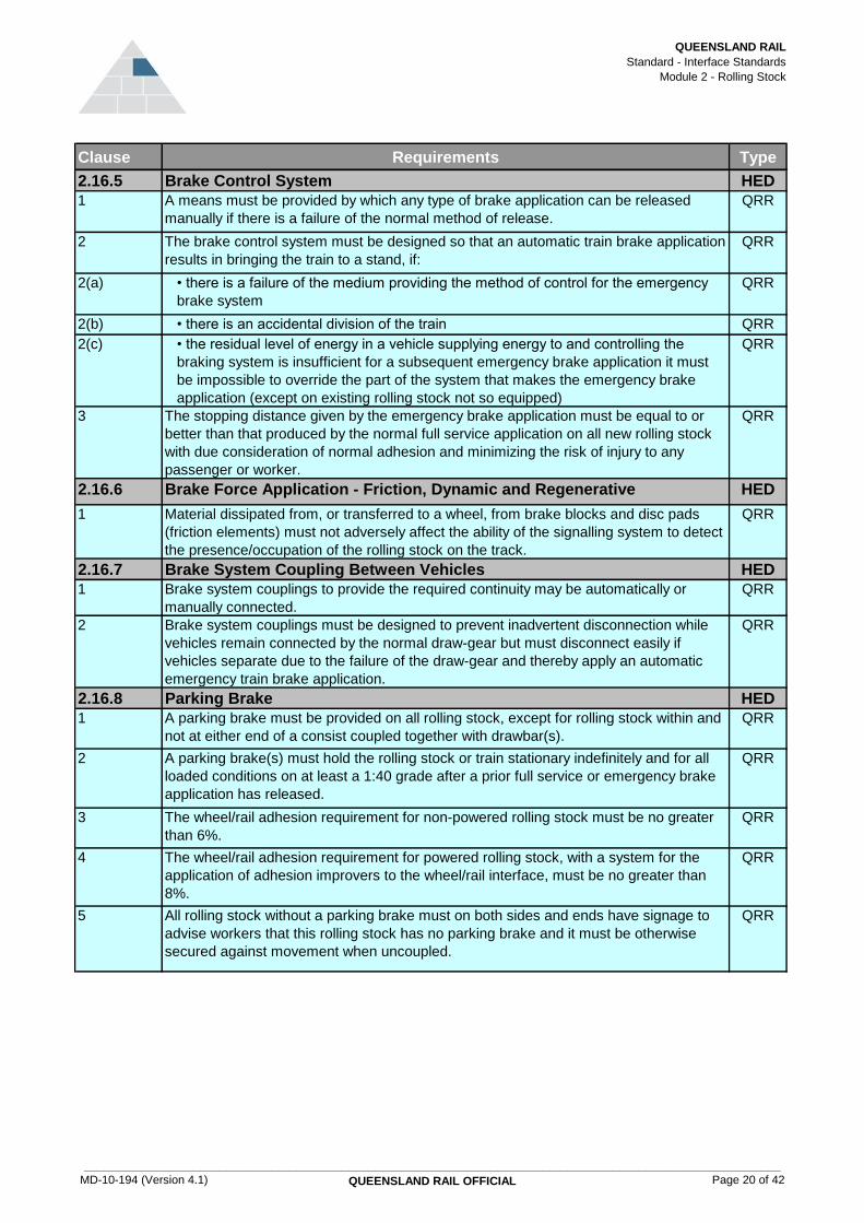
QUEENSLAND RAIL
Standard - Interface Standards
Module 2 - Rolling Stock
Clause Requirements Type
2.16.5 Brake Control System HED
1 A means must be provided by which any type of brake application can be released
manually if there is a failure of the normal method of release.
QRR
2 The brake control system must be designed so that an automatic train brake application
results in bringing the train to a stand, if:
QRR
2(a) • there is a failure of the medium providing the method of control for the emergency
brake system
QRR
2(b) • there is an accidental division of the train QRR
2(c) • the residual level of energy in a vehicle supplying energy to and controlling the
braking system is insufficient for a subsequent emergency brake application it must
be impossible to override the part of the system that makes the emergency brake
application (except on existing rolling stock not so equipped)
QRR
3 The stopping distance given by the emergency brake application must be equal to or
better than that produced by the normal full service application on all new rolling stock
with due consideration of normal adhesion and minimizing the risk of injury to any
passenger or worker.
QRR
2.16.6 Brake Force Application - Friction, Dynamic and Regenerative HED
1 Material dissipated from, or transferred to a wheel, from brake blocks and disc pads
(friction elements) must not adversely affect the ability of the signalling system to detect
the presence/occupation of the rolling stock on the track.
QRR
2.16.7 Brake System Coupling Between Vehicles HED
1 Brake system couplings to provide the required continuity may be automatically or
manually connected.
QRR
2 Brake system couplings must be designed to prevent inadvertent disconnection while
vehicles remain connected by the normal draw-gear but must disconnect easily if
vehicles separate due to the failure of the draw-gear and thereby apply an automatic
emergency train brake application.
QRR
2.16.8 Parking Brake HED
1 A parking brake must be provided on all rolling stock, except for rolling stock within and
not at either end of a consist coupled together with drawbar(s).
QRR
2 A parking brake(s) must hold the rolling stock or train stationary indefinitely and for all
loaded conditions on at least a 1:40 grade after a prior full service or emergency brake
application has released.
QRR
3 The wheel/rail adhesion requirement for non-powered rolling stock must be no greater
than 6%.
QRR
4 The wheel/rail adhesion requirement for powered rolling stock, with a system for the
application of adhesion improvers to the wheel/rail interface, must be no greater than
8%.
QRR
5 All rolling stock without a parking brake must on both sides and ends have signage to
advise workers that this rolling stock has no parking brake and it must be otherwise
secured against movement when uncoupled.
QRR
MD-10-194 (Version 4.1)
____________________________________________________________________________________________________________
QUEENSLAND RAIL OFFICIAL Page 20 of 42

QUEENSLAND RAIL
Standard - Interface Standards
Module 2 - Rolling Stock
Clause Requirements Type
2.16.9 On-Track Machine Additional Requirements HED
1 Brake systems in accordance with Section 2.16 "Brake System Requirements" must be
fitted on:
QRR
1(a) • on-track machines that can travel at speeds in excess of 60km/h and be towed in a
train by a locomotive
QRR
1(b) • on-track machines fitted with an automatic brake QRR
1(c) • any on-track machine required to control rolling stock fitted with an automatic brake QRR
2 Braking rates must be set so rail wheels can not skid on clean dry track. QRR
3 Rail mounted trailer on-track machines that do not exceed 25km/h are permitted to
have only a manually applied brake that operates on more than one wheel capable of
holding a vehicle on a 1:40 grade with not more than 6% wheel/rail adhesion.
QRR
4 On-track machines, that cannot be towed in a train by a locomotive, must have at least
two separate braking systems that operate independently from each other - one brake
for service braking, and the other a secondary brake for emergency and parking
functions.
QRR
5 The brakes for on-track machines, that cannot be towed in a train by a locomotive, are
acceptable as below:
QRR
5(a) • automatic train brake functions may be provided by the service or secondary brake QRR
5(b) • on-track machines that operate in uncoupled consist must have braking
performance exceeding the P curve but less than the A curve in Tables 1 to 3
(Appendix 2.2)
QRR
5(c) • brakes must be able to be applied without wheel lockup QRR
5(d) • wheel slide protection is not required for on-track machines that brake at less than
0.75m/s² and travel less than 80km/h
QRR
5(e) • an emergency brake application on these on-track machines must be possible at
any time from any cabin before or during a brake application by any brake system
QRR
5(f) • the stopping distance of the secondary brake must be at least compatible with the
performance for the corridor it operates on, but not less than 50% of the stopping
performance of the service brake
QRR
5(g) • the braking of the secondary brake may be preset, or uncontrolled on an on-track
machine
QRR
6 A secondary brake application must be able to be applied on all on-track machines
coupled in a consist from any personnel area on any machine at any time.
QRR
2.16.10 RRV Additional Requirements HED
1 RRVs with rubber tyres on rail must have two independent braking systems. QRR
2 Brakes on RRVs complying with the requirements for Australian Design Rules (ADRs)
will be acceptable provided:
QRR
2(a) • the service braking performance on rail is in excess of the P brake curve in Tables 1
to 3 (Appendix 2.2)
QRR
2(b) • the secondary brake operates on more than one wheel QRR
2(c) • the stopping distance of the secondary brake is at least compatible with the
performance for the corridor it operates on, but not less than 50% of the stopping
performance of the service brake
QRR
2(d) • the braking of the secondary brake may be preset, or uncontrolled QRR
2(e) • the backup brake meets the requirements to hold the vehicle indefinitely on a 1 in 40
grade with 6% wheel/rail adhesion
QRR
MD-10-194 (Version 4.1)
____________________________________________________________________________________________________________
QUEENSLAND RAIL OFFICIAL Page 21 of 42

QUEENSLAND RAIL
Standard - Interface Standards
Module 2 - Rolling Stock
Clause Requirements Type
3 All other RRVs must meet the braking requirements for on-track machines that travel at
speeds up to 60km/h.
QRR
4 Brakes fitted to RRV rail wheels that are activated by the vehicle’s braking system must
be ADR compliant.
QRR
2.17 On-Track Machines - Special Requirements HED
2.17.1 Jacking and Lift Points HED
1 On-track machines must have a method for rerailing in the event of derailment. QRR
2.17.2 Maximum Rail Stress HED
1 If an on-track machine during work is capable of inducing stresses in the rail that
exceed 90% of the rail yield stress, then an instruction must be clearly displayed in the
Operator’s Manual and near the appropriate controls indicating the correct operating
procedure to ensure the rail is not damaged.
QRR
2.17.3 On-Track Machines Pushed and Controlled by Workers at Walking Pace HED
1 The machine must be fully insulated from track circuits. QRR
2 Machines insulated from track circuits and required to be earthed must provide a
ground path through one rail only.
QRR
3 The machine must not be towed by other machines or travel in a consist. QRR
4 The machine must be able to be lifted on and off the track by workers as required. QRR
5 The machines are permitted to have only a manually applied brake that operates on
more than one wheel capable of holding a vehicle on a 1 in 40 grade with not more than
6% wheel/rail adhesion.
QRR
6 A machine without a brake must have operational procedures in place to prevent the
vehicle running away under all circumstances.
QRR
7 The machines are not required to meet any of the dynamic standard requirements. GUI
2.17.4 RRVs - Special Requirements HED
1 RRVs that travel at speeds not exceeding 60km/h and are less than 20 tonne gross
mass must comply with the requirements for on-track machine trailers except for the
following areas:
QRR
1(a) • ride performance QRR
1(b) • structural requirements QRR
2 When operating under live OverHead Line Equipment (OHLE) it must be physically
impossible for any part of a RRV to exceed 3.9m above top of rail, under any
circumstances.
QRR
3 The jacking system utilised for raising the vehicle above normal travelling height on
RRVs must provide an electrical path back to the rails unless required to be insulated to
prevent operation of track circuits.
QRR
4 If the jacking system is insulated, a permanent engraved warning plaque must be fitted
to advise that an electrical path back to the rails must be made when jacking under live
OHLE.
QRR
2.18 Rolling Stock Electromagnetic Compatibility (EMC) HED
2.18.1 General EMC Requirements HED
1 New rolling stock or electrical/electronic equipment to be used in rolling stock
modifications must be designed, built and maintained with regard to EMC in order that
they operate safely throughout their operational life. This applies to all normal and
reasonably foreseeable abnormal situations, including failures.
QRR
MD-10-194 (Version 4.1)
____________________________________________________________________________________________________________
QUEENSLAND RAIL OFFICIAL Page 22 of 42

QUEENSLAND RAIL
Standard - Interface Standards
Module 2 - Rolling Stock
Clause Requirements Type
2 As a minimum requirement, new rolling stock must comply with the requirements of
EN50121-3-1.
QRR
3 During the design phase and prior to the introduction of new rolling stock to Queensland
Rail track and as part of the EMC management plan, a detailed study of the interaction
of the new rolling stock, existing rolling stock and fixed infrastructure must be
undertaken to assess the immunity and emission issues.
QRR
4 As a minimum requirement, electrical or electronic equipment to be used as a part of a
safety critical system on a vehicle or train must comply with the emissions and immunity
requirements of EN50121-3-2.
QRR
5 During the design phase and prior to the introduction of the rolling stock modification to
the Queensland Rail network, an EMC management plan must be prepared and
submitted to Queensland Rail for review.
QRR
2.18.2 Additional Immunity Requirements HED
1 The operator must demonstrate how immunity of the rolling stock is achieved in all
normal and reasonably foreseeable abnormal situations. Immunity testing of the entire
rolling stock is not required.
QRR
2 To comply with the requirements of harmonic injection into the overhead electrical
system and also to minimise harmonic overvoltages on the overhead, the limits in
Sections 2.18.3 to 2.18.10 must be met for new rolling stock operating on the specific
overhead system types being:
QRR
2(a) • North Coast Line QRR
2(b) • Gold Coast System QRR
2(c) • Brisbane Suburban Area QRR
3 Details of non-Queensland Rail overhead networks should be obtained from that
network manager.
GUI
2.18.3 Harmonics HED
1 For new rolling stock, the individual harmonic current components per vehicle must
under no circumstances exceed the limits and related duration specified for:
QRR
1(a) • odd harmonics listed in the Figures 14 and 15 (Appendix 2.1). QRR
1(b) • even harmonics listed in the Figures 16 and 17 (Appendix 2.1). QRR
2.18.4 Total Harmonic Distortion (THD) HED
1 The total harmonic distortion (THD) must not exceed 1.5% (1 min average) of the
corresponding fundamental current component.
QRR
2.18.5 Psophometric Current HED
1 The psophometric weighted disturbing current must under no circumstance exceed 0.5
A (rms) maximum (instantaneous), measured and calculated according to EN50121-3-
1.
QRR
2.18.6 Signalling - Audio Frequency Track Circuits HED
1 Three types of track signalling are currently in use. Two of these are audio frequency
track circuits and the third type is the dc track circuit.
GUI
2 The audio frequency track circuits limit the tolerable levels of the individual components
of the line current to the values given in the tables referred to below, to avoid signal
replication. There must be no modulation within the frequency range given in Figures
18 and 19 (Appendix 2.1) between the two centre frequencies f1 and f2.
QRR
2.18.7 Magnetic Field HED
1 The train must not produce a magnetic flux density (dc) at top of rail level of more than
the limit in Figure 20 (Appendix 2.1).
QRR
MD-10-194 (Version 4.1)
____________________________________________________________________________________________________________
QUEENSLAND RAIL OFFICIAL Page 23 of 42
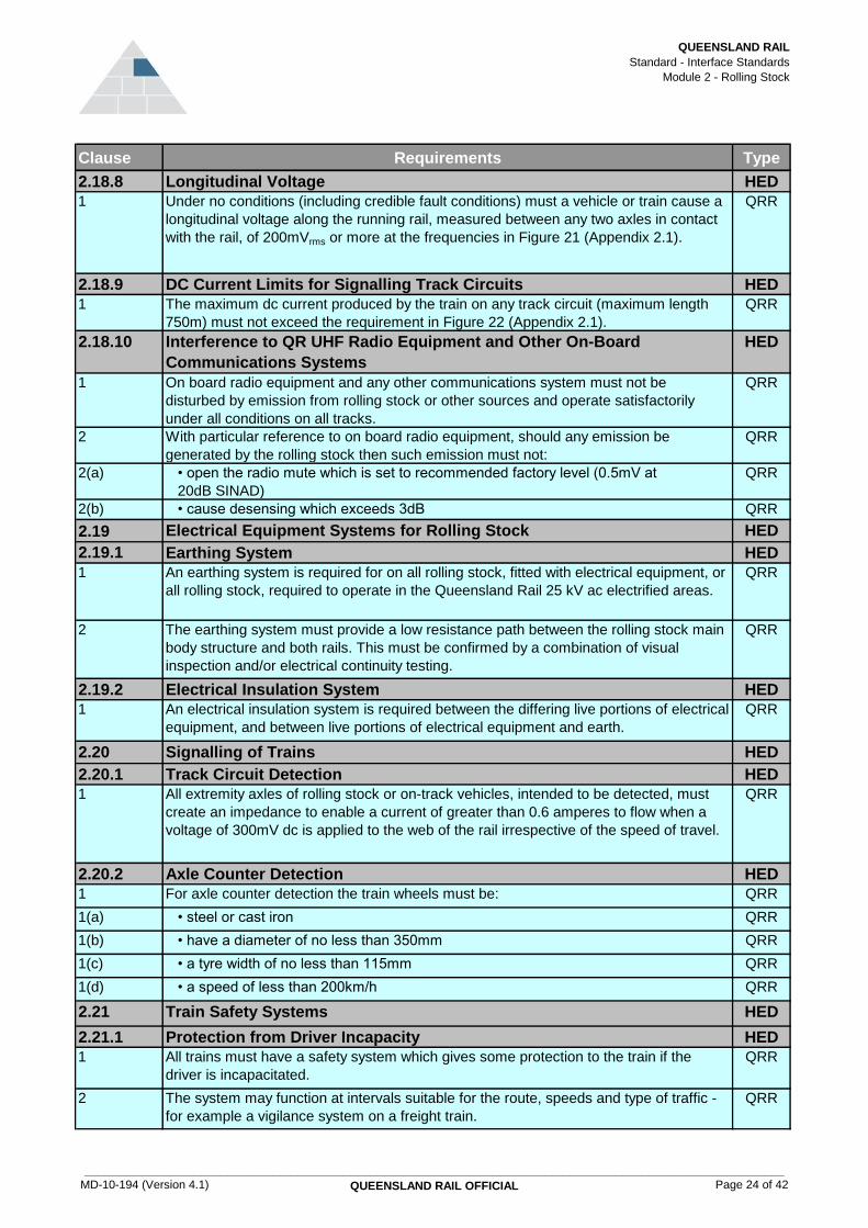
QUEENSLAND RAIL
Standard - Interface Standards
Module 2 - Rolling Stock
Clause Requirements Type
2.18.8 Longitudinal Voltage HED
1 Under no conditions (including credible fault conditions) must a vehicle or train cause a
longitudinal voltage along the running rail, measured between any two axles in contact
with the rail, of 200mVrms or more at the frequencies in Figure 21 (Appendix 2.1).
QRR
2.18.9 DC Current Limits for Signalling Track Circuits HED
1 The maximum dc current produced by the train on any track circuit (maximum length
750m) must not exceed the requirement in Figure 22 (Appendix 2.1).
QRR
2.18.10 Interference to QR UHF Radio Equipment and Other On-Board
Communications Systems
HED
1 On board radio equipment and any other communications system must not be
disturbed by emission from rolling stock or other sources and operate satisfactorily
under all conditions on all tracks.
QRR
2 With particular reference to on board radio equipment, should any emission be
generated by the rolling stock then such emission must not:
QRR
2(a) • open the radio mute which is set to recommended factory level (0.5mV at
20dB SINAD)
QRR
2(b) • cause desensing which exceeds 3dB QRR
2.19 Electrical Equipment Systems for Rolling Stock HED
2.19.1 Earthing System HED
1 An earthing system is required for on all rolling stock, fitted with electrical equipment, or
all rolling stock, required to operate in the Queensland Rail 25 kV ac electrified areas.
QRR
2 The earthing system must provide a low resistance path between the rolling stock main
body structure and both rails. This must be confirmed by a combination of visual
inspection and/or electrical continuity testing.
QRR
2.19.2 Electrical Insulation System HED
1 An electrical insulation system is required between the differing live portions of electrical
equipment, and between live portions of electrical equipment and earth.
QRR
2.20 Signalling of Trains HED
2.20.1 Track Circuit Detection HED
1 All extremity axles of rolling stock or on-track vehicles, intended to be detected, must
create an impedance to enable a current of greater than 0.6 amperes to flow when a
voltage of 300mV dc is applied to the web of the rail irrespective of the speed of travel.
QRR
2.20.2 Axle Counter Detection HED
1 For axle counter detection the train wheels must be: QRR
1(a) • steel or cast iron QRR
1(b) • have a diameter of no less than 350mm QRR
1(c) • a tyre width of no less than 115mm QRR
1(d) • a speed of less than 200km/h QRR
2.21 Train Safety Systems HED
2.21.1 Protection from Driver Incapacity HED
1 All trains must have a safety system which gives some protection to the train if the
driver is incapacitated.
QRR
2 The system may function at intervals suitable for the route, speeds and type of traffic -
for example a vigilance system on a freight train.
QRR
MD-10-194 (Version 4.1)
____________________________________________________________________________________________________________
QUEENSLAND RAIL OFFICIAL Page 24 of 42

QUEENSLAND RAIL
Standard - Interface Standards
Module 2 - Rolling Stock
Clause Requirements Type
3 Operation of the system must result in the train being brought to a stop. QRR
2.21.2 Protection from Exceeding Limit of Authority HED
1 All trains must have a safety system which gives some protection against exceeding the
limit of authority.
QRR
2 The minimum level is to alert the driver that the train is approaching: QRR
2(a) • a station, and/or QRR
2(b) • a restricted signal QRR
3 Higher levels of protection, such as ATP, can replace this warning with other system
features.
QRR
4 Operation of the system must result in the train being brought to a stop. QRR
2.21.3 Protection from Exceeding Speed Limit HED
1 Self propelled rolling stock that can travel over 25km/h must be fitted with a speed
indicator, accurate to the lesser of 5km/h or 10% of the speed reading, visible from any
driving position and calibrated in kilometres per hour.
QRR
2.21.4 On Track Machines HED
1 On track machines that travel at speeds not exceeding 60km/h and are less than 20
tonne gross mass are exempt from the above clauses 2.21.1 and 2.21.2.
QRR
2 On track machines that do not have a vigilance system and do not come to rest
automatically in work and travel modes must have a deadman device if there is only
one operator.
QRR
3 On track machines may suppress the vigilance, station protection or AWS system when
in work mode or stationary.
QRR
2.21.5 Infrastructure Based Systems HED
1 Where train safety systems interface with infrastructure components provided by
Queensland Rail (eg SPD, AWS, ATP), the rolling stock components must be
compatible with the existing infrastructure components.
QRR
2 Details of the infrastructure components and routes they are installed on are available
from Queensland Rail Access and Business Strategy.
GUI
2.21.6 Automatic Train Protection (ATP) HED
1 Where a train utilises ATP, it must be fail-safe and apply the brakes, either with a full
service brake or emergency brake application, when the ATP system predicts or
detects an unsafe condition such as speed too high, potential or real signal passed at
danger.
QRR
2 Trains which utilise ATP must also have an alerting system. When the train enters ATP
territory, the ATP system must become active and suppress the alerting system. On
exiting ATP territory or whilst driving in ATP territory with the ATP system disabled, the
alerting system must be enabled.
QRR
2.21.7 Station Protection (SP) HED
1 Where SP is utilised, the leading vehicle must be fitted with a fail safe, magnetic
detection device(s) to detect the station protection and AWS signal aspect magnets
located on the track.
QRR
2 On a single vehicle, it is acceptable to have one detector head at one end. QRR
3 On a multiple vehicle unit able to be driven from either end, there must be a detector at
each end of the unit.
QRR
2.21.8 Automatic Warning System (AWS) HED
1 Rolling stock which utilises AWS must be fitted with a fail safe AWS that receives signal
aspect information from magnets placed on the track before the signal it repeats.
QRR
MD-10-194 (Version 4.1)
____________________________________________________________________________________________________________
QUEENSLAND RAIL OFFICIAL Page 25 of 42

QUEENSLAND RAIL
Standard - Interface Standards
Module 2 - Rolling Stock
Clause Requirements Type
2 The track magnets must indicate to the AWS whether the signal is: QRR
2(a) • a proceed signal aspect (green) is recognised by the presence, within 0.5 seconds,
of an energised south pole electromagnet immediately following a north pole.
QRR
2(b) • a restricted signal aspect (double yellow, yellow, flashing yellow or red) is denoted by
a north pole magnet
QRR
2.21.9 Magnet Receiver HED
1 The magnet receiver must have the following properties: QRR
1(a) • the magnet receiver must be mounted at a height, with new wheels, of 150mm
above top of rail and on the longitudinal centre line of the rolling stock
QRR
1(b) • the magnet detector device must be capable of detecting a magnet that has a
minimum flux of 35 Gauss measured 125mm vertically above the top of the casing.
The top of the casing is 0 to 10mm below the head of the rail. This flux is constant
over an area ±60mm in the transverse and ±90mm in the longitudinal directions from
the magnet centreline
QRR
2.22 Powered Rolling Stock Operated By Remote Control HED
1 The term ''remote control locomotive'' (RCL) refers to a locomotive or other powered
rolling stock which can be operated by a person not physically located within the
locomotive cab by using a radio or other transmitter and receiver system or attached
cable. This does not include distributed power.
QRR
2 Each remote control unit (RCU) should, at a minimum, have the following features: GUI
2(a) • directional control GUI
2(b) • graduated throttle or speed control GUI
2(c) • graduated locomotive independent brake application and release GUI
2(d) • train brake application and release control if this is a feature of the powered rolling
stock
GUI
2(e) • audible warning device control (horn) GUI
2(f) • headlight control GUI
2(g) • emergency air brake application switch if this is a feature of the powered rolling
stock
GUI
2(h) • switch or control to eliminate tractive effort to the locomotive GUI
3 Although an RCU can have the capability to control, at different times, different
locomotives equipped with remote-control systems, it must be designed to be capable
of controlling only one remote control equipped locomotive at a time. (A locomotive may
consist of one or more locomotives operated in multiple from a single control).
QRR
4 An RCU having the capability to control more than one RCL must have a means to lock
in one RCL ''assignment address'' to prevent simultaneous control over more than one
locomotive.
QRR
5 Each RCL must respond only to the RCU assigned to that locomotive. QRR
6 The RCU must be designed to require at least two separate actions by the operator
before RCL movement can begin (in order to prevent accidental movement).
QRR
7 When an RCU's signal to the RCL is interrupted for a set period, not to exceed five
seconds, the remote-control system must:
QRR
7(a) • apply a full service application of the locomotive and train brakes (if the train brakes
are connected to the RCL)
QRR
7(b) • disable locomotive tractive effort QRR
MD-10-194 (Version 4.1)
____________________________________________________________________________________________________________
QUEENSLAND RAIL OFFICIAL Page 26 of 42

QUEENSLAND RAIL
Standard - Interface Standards
Module 2 - Rolling Stock
Clause Requirements Type
8 If an RCU is equipped with an ''on'' and ''off'' switch, the switch, when moved from ''on''
to ''off'' position, must result in:
QRR
8(a) • application of the locomotive and train brakes (if connected) QRR
8(b) • disabling of locomotive tractive effort QRR
9 Each RCL must have a distinct and unambiguous audible or visual warning device that
indicates to nearby personnel that the locomotive is under active remote control and
subject to movement.
QRR
10 Each RCU must be equipped with an operator alertness device requiring
acknowledgement by the operator within a timing sequence.
QRR
11 Failure to acknowledge alertness within the timing sequence must result in: QRR
11(a) • application of the locomotive and train brakes (if connected) QRR
11(b) • disabling of locomotive tractive effort QRR
12 Each RCU must have a tilt feature that, when tilted to a predetermined angle, will result
in:
QRR
12(a) • application of the locomotive and train brakes (if connected) QRR
12(b) • disabling of locomotive tractive effort QRR
13 If the RCU is equipped with a ''tilt bypass'' system enabling the tilt protection feature to
be temporarily disabled, the bypass feature must deactivate after a set time, unless
reactivated by the remote control operator.
QRR
14 If a protective alarm on the RCL would normally initiate safety action such as shutdown
or a brake application then these must also apply when the RCL is in remote operation.
The device must be manually reset on board the RCL.
QRR
15 When the RCL is changed from manual to remote or from remote to manual modes,
application of the locomotive and train brakes (if connected) must be initiated to prevent
unauthorised use of the system.
QRR
16 The control unit and the RCL must meet the EMF requirements of this module. QRR
17 The remote control operator must hold authority for the vehicle to occupy the section of
track, whether under a safeworking system or under local control (yards etc).
QRR
18 The remote control operator must always be able to clearly determine the location of
the RCL in relation to the limit of authority.
QRR
2.23 Additional Requirements - Non Standard Rolling Stock HED
1 The requirements in this standard have been based on conventional rolling stock
operated in the usual manner. Additional requirements for rolling stock and situations
not covered by this standard may be specified by Queensland Rail Network Business or
determined during the interface risk assessment.
QRR
MD-10-194 (Version 4.1)
____________________________________________________________________________________________________________
QUEENSLAND RAIL OFFICIAL Page 27 of 42

QUEENSLAND RAIL
Standard - Interface Standards
Module 2 - Rolling Stock
Appendix 2.1
Figure 1 - Dimensions for Track Twist Test
3m
D
1
N
105mm Max.
High Rail
Low Rail
Horizontal
Horizontal
Horizontal
Measure wheel load
at the base of the
ramp. Point A
NOT TO SCALE
H
Point A
Point B
Point C
MD-10-194 (Version 4.1)
____________________________________________________________________________________________________________
QUEENSLAND RAIL OFFICIAL Page 28 of 42

QUEENSLAND RAIL
Standard - Interface Standards
Module 2 - Rolling Stock
Test Number D (mm) N
1 20 300
2 25 400
3 30 400
where:
P2 = Force (kN) P0 = Vehicle static wheel load (kN)
Mu = Vehicle unsprung Mass per wheel (kg) Mt = Equivalent track mass (kg)
Kt = Equivalent track stiffness (MN/m) Ct = Equivalent track damping (kNs/m)
v = Vehicle velocity (m/s)
2 = Included angle of dip, nominally 0.01 or 0.014 radians
Rail (kg/m) Kt (MN/m) Ct (kNs/m)
>41 109 52
Total Joint
Angle
(Radians)
P2 Force Limit
0.01 200
0.01 203
Figure 5 - P2 Force Limit
Queensland Rail Network Track Categories
Track categories 7, 8, 9 and 10 except as identified below
Track categories 5 and 6.
Track category 7 only for:
• Rockhampton to Durroburra
• Kaili to Townsville
• Townsville to Mt Isa
Figure 2 - Limiting Values for Track Twist Test (refer Figure 1)
Figure 3 - P2 Force Calculation
Figure 4 - Values of Kt, Mt and Ct
All other areas
Lines maintained to category 7 or better
Lines maintained to category 7 or better
Lines on Which the Rolling Stock Will
Operate
Mt (kg)
133
MD-10-194 (Version 4.1)
____________________________________________________________________________________________________________
QUEENSLAND RAIL OFFICIAL Page 29 of 42

QUEENSLAND RAIL
Standard - Interface Standards
Module 2 - Rolling Stock
Top
Versine
Twist
Top & Versine
Versine & Top
Twist & Versine
Versine & Twist
Top
All except single
parameter top
Figure 6 - Track Defect Values
120% for Versine with 25% for Top of fig 1
appendix 1.1
120% for Twist with 60% for versine of fig 1
appendix 1.1
120% for versine with 25% for twist of fig 1
appendix 1.1
Single Parameter Defects
Combined Defects
Repeated Defects for both Single
Parameter and Combined Defects
Cyclic Top Irregularities
75% of fig 1 appendix 1.1
120% of fig 1 appendix 1.1
120% of fig 1 appendix 1.1
120% of fig 1 appendix 1.1
120% for Top with 60% for Versine of fig 1
appendix 1.1
40% of fig 1 appendix 1.1
MD-10-194 (Version 4.1)
____________________________________________________________________________________________________________
QUEENSLAND RAIL OFFICIAL Page 30 of 42

QUEENSLAND RAIL
Standard - Interface Standards
Module 2 - Rolling Stock
Figure 7 - Wheel Profile LW3
MD-10-194 (Version 4.1)
____________________________________________________________________________________________________________
QUEENSLAND RAIL OFFICIAL Page 31 of 42

QUEENSLAND RAIL
Standard - Interface Standards
Module 2 - Rolling Stock
End Point Coordinate X mm Coordinate Y mm Centre
E1 127.0000 37.1523
E2 121.3781 31.5305
E3 105.8781 29.9805
E4 69.9911 28.7842
80.9850 -301.0326 C1
E5 58.7785 28.2194
76.2745 -231.1912 C2
E6 48.5331 27.3245
59.2029 -72.1046 C3
E7 41.3056 26.2808
45.8694 1.1925 C4
E8 34.8653 24.1960
40.4753 12.4687 C5
E9 28.2593 16.9150
E10 25.2160 8.5537
E11 13.0000 0.0000
E12 0.0000 13.0000
End Point Coordinate X mm Coordinate Y mm Centre
E1 140.0000 37.8657
E2 134.3781 32.2638
E3 114.8781 30.2638
E4 69.9911 28.7842
80.9850 -301.0326 C1
E5 58.7785 28.2194
76.2745 -231.1912 C2
E6 48.5331 27.3245
59.2029 -72.1046 C3
E7 41.3056 26.2808
45.8694 1.1925 C4
E8 34.8653 24.1960
40.4753 12.4687 C5
E9 28.2593 16.9150
E10 25.2160 8.5537
E11 13.0000 0.0000
E12 0.0000 13.0000
Figure 8 - Coordinates for LW3 Profile
Table 8A - For nominal wheel width A = 127mm
Table 8B - For nominal wheel width A = 140mm
MD-10-194 (Version 4.1)
____________________________________________________________________________________________________________
QUEENSLAND RAIL OFFICIAL Page 32 of 42

QUEENSLAND RAIL
Standard - Interface Standards
Module 2 - Rolling Stock
Dimension "B"
mm
6 @ 45 degrees
Figure 9 - Wheel Profile LW2
Figure 10 - Wheel Chamfer
Nominal Wheel Width "A"
>= 127
MD-10-194 (Version 4.1)
____________________________________________________________________________________________________________
QUEENSLAND RAIL OFFICIAL Page 33 of 42
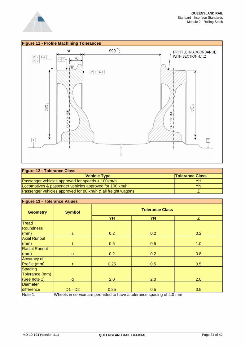
QUEENSLAND RAIL
Standard - Interface Standards
Module 2 - Rolling Stock
Tolerance Class
YH
YN
Z
YH YN Z
Tread
Roundness
(mm) s 0.2 0.2 0.2
Axial Runout
(mm) t 0.5 0.5 1.0
Radial Runout
(mm) u 0.2 0.2 0.8
Accuracy of
Profile (mm) r 0.25 0.5 0.5
Spacing
Tolerance (mm)
(See note 1) q 2.0 2.0 2.0
Diameter
difference D1 - D2 0.25 0.5 0.5
Note 1: Wheels in service are permitted to have a tolerance spacing of 4.0 mm
Figure 11 - Profile Machining Tolerances
Figure 12 - Tolerance Class
Figure 13 - Tolerance Values
Tolerance Class
Passenger vehicles approved for speeds > 100km/h
Vehicle Type
Locomotives & passenger vehicles approved for 100 km/h
Passenger vehicles approved for 80 km/h & all freight wagons
Geometry Symbol
MD-10-194 (Version 4.1)
____________________________________________________________________________________________________________
QUEENSLAND RAIL OFFICIAL Page 34 of 42

QUEENSLAND RAIL
Standard - Interface Standards
Module 2 - Rolling Stock
DurationLimits (Amps)
Normal Operation
Limits (Amps)
Abnormal Operation
- 0.4 0.4
10 s 20 3
10 s 1 1
10 s 1 0.6
1.5 s 0.5 0.1
10 s 0.6 0.6
10 s 0.35 0.35
DurationLimits (Amps)
Normal Operation
Limits (Amps)
Abnormal Operation
- 0.0325 0.4
10 s 0.650 3
10 s 0.650 1
10 s 0.13 0.6
1.5 s 0.13 0.1
10 s 0.13 0.6
10 s 0.13 0.35
Duration
2nd - 8th Harmonics 10 s
10th - 18th Harmonics 10 s
20th - 58th Harmonics 1.5 s
10 s
Duration
2nd - 8th Harmonics 10 s
10th - 18th Harmonics 10 s
20th - 58th Harmonics 1.5 s
10 s
Figure 15 - Odd Harmonics Gold Coast System and Brisbane Suburban Area
Figure 16 - Even Harmonics North Coast Line
Figure 17 - Even Harmonics Gold Coast System and Brisbane Suburban Area
0.25
0.25
0.3
Current Component Limits (Amps) Normal / Abnormal Operation
61st - 73rd Harmonics
75th and above
Current Component
3rd - 9th Harmonics
11th - 19th Harmonics
21st - 27th Harmonics
29th - 59th Harmonics
60th and above
0.13
0.13
0.13
0.13
60th and above
Limits (Amps) Normal / Abnormal Operation
2
75th and above
Current Component
29th - 59th Harmonics
61st - 73rd Harmonics
11th - 19th Harmonics
21st - 27th Harmonics
d.c. component
3rd - 9th Harmonics
Current Component
d.c. component
Figure 14 - Odd Harmonics North Coast Line
MD-10-194 (Version 4.1)
____________________________________________________________________________________________________________
QUEENSLAND RAIL OFFICIAL Page 35 of 42

QUEENSLAND RAIL
Standard - Interface Standards
Module 2 - Rolling Stock
f1 f2 RMS Level Time
1532 Hz 1566 Hz 100 mA rms 1.5 s
1682 Hz 1716 Hz 100 mA rms 1.5 s
1831 Hz 1865 Hz 100 mA rms 1.5 s
1979 Hz 2013 Hz 100 mA rms 1.5 s
2129 Hz 2163 Hz 100 mA rms 1.5 s
2129 Hz 2163 Hz 100 mA rms 1.5 s
2279 Hz 2313 Hz 100 mA rms 1.5 s
2428 Hz 2462 Hz 100 mA rms 1.5 s
2576 Hz 2610 Hz 100 mA rms 1.5 s
f1 f2 RMS Level Time
1690 Hz 1710 Hz 100 mA rms 1.5 s
1990 Hz 2010 Hz 100 mA rms 1.5 s
2290 Hz 2310 Hz 100 mA rms 1.5 s
2590 Hz 2610 Hz 100 mA rms 1.5 s
RMS Level
(Nominal)Time
3.8 Amps 0.25 s
The modulation rate between f1 and f2 shall not be between 10 and 30 Hz. The 3
dB bandwidth of centre frequencies can be taken to be 6 Hz.
Time
for times shorter than 0.01 seconds
Figure 18 - Limits for Components of Line Current to avoid Signal
Interference - ML type track circuits
Centre Frequencies
Centre Frequencies
Figure 19 - Limits for Components of Line Current to avoid Signal
Interference - CSEE type track circuits
The modulation rate between f1 and f2 shall not be between 1 and 15 Hz. The 3
dB bandwidth of centre frequencies can be taken to be 6 Hz. Note that the
fundamental supply frequency can vary between 49.5 Hz and 50.5 Hz.
Figure 20 - Magnetic Flux Density Limits
24 mT
2.4 x 10^-6 / t^2 T
where t is the time in seconds
Flux Density
for times longer than 0.01 seconds
Figure 21 - Logitudinal Voltage Limits
Figure 22 - Current Limits
Bandwidth (-3 dB points)
d.c. (0 Hz) - 2.4 Hz
RMS Level
200 mV rms
Bandwidth (-3 dB points)
d.c. (0 Hz) - 2.4 Hz
MD-10-194 (Version 4.1)
____________________________________________________________________________________________________________
QUEENSLAND RAIL OFFICIAL Page 36 of 42

QUEENSLAND RAIL
Standard - Interface Standards
Module 2 - Rolling Stock
Line Max. Axle Load (t) Min. Bogie Axle
Spacing (mm)
Min. Bogie to Bogie
Axle Spacing (mm)
Min. End Axle to
Couple Line (mm)
Vehicle A 20 1675 4549 1050
Vehicle A 20 1675 7695 2370
Vehicle A 15.75 1675 8685 1392
Vehicle A 10.62 1675 TBA TBA
Line Max. Axle Load (t) Min. Bogie Axle
Spacing (mm)
Min. Bogie to Bogie
Axle Spacing on
same vehicle
(for C0-C0)
Min. End Axle to
Coupling Line (mm)
Vehicle A 19.5 1800 9216 2500
Vehicle B 20 1900 9400 2500
Vehicle A 19.5 1800 9216 2500
Vehicle B 20 1900 9400 2500
Vehicle A 15.75 1900 6000 2175
Vehicle A 10.62 3 axles in 3245mm 3060 1917
15.75t axle load - all routes
10.62t axle load - all routes
Townsville to Mt Isa - 20t axle load lines
North Coast Line - 20t Axle Load Lines
15.75t axle load - all routes
10.62t axle load - all routes
Figure 23 - Axle Loads and Spacings - 4 Axle, 2 Bogie Vehicles
Figure 24 - Axle Loads and Spacings - 6 Axle, 2 Bogie Vehicles
Townsville to Mt Isa - 20t axle load lines
North Coast Line - 20t Axle Load Lines
MD-10-194 (Version 4.1)
____________________________________________________________________________________________________________
QUEENSLAND RAIL OFFICIAL Page 37 of 42

QUEENSLAND RAIL
Standard - Interface Standards
Module 2 - Rolling Stock
Defect Class Description Operating Restrictions
1 Single flat length
less than 25 mm.
Normal Speed
2 Single flat length
between 25 mm
and 40 mm OR
multiple Class 1
flats.
Normal Speed
3 Single flat length
between 40 mm
and 60 mm or
multiple class 2 flats
Normal Speed
4 Single flat length
between 60 mm
and 100 mm OR
multiple Class 3
Flats
Speed 40 km/h
Maximum
5 Single flat length
greater than 100
mm
Move to siding at
restricted speed less
than 40km/h.
Defect
Category
Description Operating Restrictions
1 Classification not
relevant
Normal Speed
2 Classification not
relevant
Normal Speed
3 Light surface
smearing too small
to measure with a
standard rule.
Normal Speed
4 (i) Scale height up to
5mm
Speed 25 km/h
Maximum
4 (ii) Scale height 5mm
to 10mm
Speed 15 km/h
Maximum
4 (iii) Scale height 10mm
to 15 mm
Speed 5 km/h Maximum
5 Scale greater than
15mm
Not to move until wheel
is rectified
If found pre-trip or at a depot, the wheel
must not enter service. If found en-route,
Figure 25 - Wheel Flats
Action
Figure 26 – Built Up Tread
Re-examine carefully to ensure that no
Class 3 Spalls exist.
Work out of service
Action
If found pre-trip or at a depot, the wheel
must not enter service. If found en-route
continue at reduced speed with the brakes
cut out or remove from service..
Remove built-up metal in the section before
movement to the nearest siding at a speed
assessed after inspection
No action required
If found pre-trip or at a depot, the wheel
must not enter service. If found en-route,
No action
No action
Examine brake gear for defects.
If found pre-trip or at a depot, the wheel
must not enter service. If found en-route,
If found pre-trip or at a depot, the wheel
must not enter service. If found en-route,
MD-10-194 (Version 4.1)
____________________________________________________________________________________________________________
QUEENSLAND RAIL OFFICIAL Page 38 of 42

QUEENSLAND RAIL
Standard - Interface Standards
Module 2 - Rolling Stock
Defect
Category
Action Operating Restrictions
1 No action required Normal Speed
2 Re-examine carefully
to ensure that no
Class 3 Spalls exist.
Defects must be
reported
Normal Speed
3 Locomotives &
Passenger: Work out
of service within 14
days. Wagons & Infra
Mntce: Work out of
service
Normal Speed
4 If found pre-trip or at a
depot, the wheel must
not enter service. If
found en-route
continue at reduced
speed with the brakes
cut out or remove
from service.
Maximum Speed 40
km/h
Work out of service Remove from service
35
Approaching 3mm 3
Approaching 22mm 22
Less than 5 degrees
from vertical
Figure 27 – Shelled Tread and Spalling
Description
Spalled regions less than 12 mm in
diameter. Maximum 10% wheel coverage
Spalled regions less than 25 mm in
diameter. Maximum 20% wheel
coverage. The edges of the spalls may be
sharp and jagged.
Spalled regions greater than 25 mm in
diameter. The edges of the spalls may be
sharp and jagged. Maximum 50% wheel
coverage
Extensive spalling 3 mm or more deep,
sharp and jagged. More than 50% wheel
coverage.
Minimum flange angle
Maximum flange height (mm) above tread running surface
Maximum tread hollowing (mm)
Minimum flange thickness (mm) measured with standard
Figure 28 - Tread and Flange Limits
Dimension
MD-10-194 (Version 4.1)
____________________________________________________________________________________________________________
QUEENSLAND RAIL OFFICIAL Page 39 of 42

QUEENSLAND RAIL
Standard - Interface Standards
Module 2 - Rolling Stock
Appendix 2.2 - Train Stopping Distances
Initial Speed (km/h) 5 10 15 20 25 30 35 40 45 50 55 60
Braking Curve A - - - 11 17 25 34 44 56 69 83 99
P - - - 40 54 71 89 109 131 154 180 207
F - - - 84 119 159 205 257 314 377 446 520
I - - - 193 254 319 388 463 542 626 715 808
N - - - 133 180 232 290 353 422 496 576 661
S - - - 140 189 243 304 370 442 519 602 691
T - - - 117 161 210 265 325 392 463 541 624
W - - - 129 175 227 284 348 417 491 571 657
Initial Speed (km/h) 65 70 75 80 85 90 95 100 105 110 115 120
Braking Curve A 116 135 155 176 199 223 249 276 304 333 364 397
P 236 268 300 335 372 410 450 492 536 582 630 679
F 600 685 772 864 960 1062 1168 1280 1396 1518 - -
I 906 1009 1117 1229 1346 1468 - - - - - -
N 752 848 950 1057 1170 1288 - - - - - -
S 785 885 991 1102 1219 1341 - - - - - -
T 713 807 - - - - - - - - - -
W 749 846 949 1057 1172 1291 - - - - - -
Initial Speed (km/h) 125 130 135 140 145 150 155 160 165 170
Braking Curve A 431 466 502 540 579 620 662 705 750 796
P 797 858 921 986 1053 1123 1195 1269 1345 1423
Table 1 - Stopping Distances (metres) - Tangent Level Track
MD-10-194 (Version 4.1) QUEENSLAND RAIL OFFICIAL Page 40 of 42

QUEENSLAND RAIL
Standard - Interface Standards
Module 2 - Rolling Stock
Initial Speed (km/h) 5 10 15 20 25 30 35 40 45 50 55 60
Braking Curve A - - - 13 20 29 39 51 65 80 97 115
P - - - 43 59 78 99 122 148 175 205 238
F - - - 147 212 289 377 476 587 709 843 988
I - - - 236 321 415 519 634 759 893 1038 1193
N - - - 202 288 388 503 631 774 930 1101 1287
S - - - 218 311 419 543 682 837 1007 1192 1393
T - - - 196 283 386 504 638 787 951 1131 1326
W - - - 207 297 402 523 660 812 979 1161 1360
Initial Speed (km/h) 65 70 75 80 85 90 95 100 105 110 115 120
Braking Curve A 135 157 180 205 232 260 289 320 353 388 424 462
P 272 309 348 389 433 479 527 577 629 684 741 801
F 1144 1312 1491 1682 1884 2097 2322 2558 2806 3065 - -
I 1358 1533 1718 1914 2119 2335 - - - - - -
N 1486 1699 1927 2169 2425 2695 - - - - - -
S 1609 1841 2088 2350 2628 2921 - - - - - -
T 1537 1763 - - - - - - - - - -
W 1573 1802 2046 2306 2581 2871 - - - - - -
Initial Speed (km/h) 125 130 135 140 145 150 155 160 165 170
Braking Curve A 501 542 584 628 674 721 770 820 873 926
P 999 1076 1156 1239 1325 1413 1505 1599 1696 1796
Table 2 - Stopping Distance Curves on Tangent Down 1 in 50 Track
MD-10-194 (Version 4.1) QUEENSLAND RAIL OFFICIAL Page 41 of 42

QUEENSLAND RAIL
Standard - Interface Standards
Module 2 - Rolling Stock
Initial Speed (km/h) 5 10 15 20 25 30 35 40 45 50 55 60
Braking Curve A - - - 10 15 22 30 39 49 60 73 87
P - - - 37 51 65 82 100 119 140 162 186
F - - - 66 92 120 152 188 227 269 315 365
I - - - 178 231 287 347 410 475 544 615 690
N - - - 116 154 194 239 286 338 392 450 511
S - - - 122 161 204 250 300 353 409 469 533
T - - - 100 134 171 211 255 303 354 408 466
W - - - 111 147 187 231 278 328 382 439 499
Initial Speed (km/h) 65 70 75 80 85 90 95 100 105 110 115 120
Braking Curve A 102 118 136 155 175 196 218 242 266 292 320 348
P 212 239 268 298 330 363 398 435 473 512 553 596
F 417 474 533 596 663 733 806 883 964 1047 - -
I 767 848 932 1019 1109 1202 - - - - - -
N 576 644 716 790 869 950 - - - - - -
S 600 670 744 821 902 986 - - - - - -
T 527 592 - - - - - - - - - -
W 564 631 702 777 855 936 - - - - - -
Initial Speed (km/h) 125 130 135 140 145 150 155 160 165 170
Braking Curve A 378 408 440 474 508 544 581 619 658 699
P 670 720 772 826 882 939 999 1060 1123 1187
Table 3 - Stopping Distance Curves on Tangent Up 1 in 50 Track
MD-10-194 (Version 4.1) QUEENSLAND RAIL OFFICIAL Page 42 of 42

Version: 4. Updated: 04/09/2017 Policy: Safety Policy
Interface Standards Module 3 Safeworking
MD-10-194 QUEENSLAND RAIL OFFICIAL

QUEENSLAND RAIL
Standard - Interface Standards
Module 3 - Safeworking
3 REQUIREMENTS 3
3.1 Train Route Acceptance 3
3.1.1 General Requirements 3
3.1.2 Train Criteria Factors 3
3.1.3 Route Criteria Factors 3
3.1.4 Interface Risk Assessment 4
3.1.5 Interface Risk Management Plan (IRMP) 4
3.1.6 On-Track Testing 5
3.1.7 Environmental Risk Management 5
3.1.8 Train Route Acceptance (TRA) 5
3.2 Rolling Stock Authorisation 6
3.2.1 General Requirements 6
3.2.2 Compliance Plan 6
3.2.3 Certificate of Design Conformance 6
3.2.4 Certificate of Type Testing Conformance 6
3.2.5 Certificate of Construction Conformance 7
3.2.6 Certificate of Interface Compliance 7
3.2.7 Certificate of Compliance - Rolling Stock Configurations 7
3.2.8 Authorisation of Rolling Stock 7
3.2.9 Authorisation of Rolling Stock Configurations 8
3.2.10 Interim Authorisation 8
3.2.11 Rolling Stock Data 8
3.2.12 Rolling Stock Configuration Data 9
3.3 Safeworking 9
3.3.1 General Requirements 9
3.3.2 Transportation of Dangerous Goods 9
Table of Contents
MODULE 3 - SAFEWORKING
MD-10-194 (Version 4.1)
____________________________________________________________________________________________________________
QUEENSLAND RAIL OFFICIAL Page 2 of 9

QUEENSLAND RAIL
Standard - Interface Standards
Module 3 - Safeworking
Clause Requirements Type
3 REQUIREMENTS HED
3.1 Train Route Acceptance HED
3.1.1 General Requirements HED
1 Rolling stock operators proposing to operate trains on the Queensland Rail network
must apply for access to Queensland Rail Access and Business Strategy and prior to
any operation occurring must obtain:
QRR
1(a) • an access agreement or internal access interface agreement QRR
1(b) • an Authority To Travel (ATT) for on-track tests or ad-hoc train movements QRR
1(c) • Train Route Acceptance (TRA) QRR
2 As part of the access application process, the interface risks posed by the operation of
a particular train service on the network must be assessed and managed through the
train route acceptance process described in MD-10-170 Train Route Acceptance.
QRR
3 Rolling stock, and the rolling stock configuration, must be certified by the rolling stock
operator as complying with the interface standards and authorised by Queensland Rail
Access and Business Strategy prior to operation on the network.
QRR
4 An item of rolling stock can be tested or audited at any time to ascertain if it is compliant
with the interface standards.
QRR
3.1.2 Train Criteria Factors HED
1 Train criteria to be considered by a rolling stock operator in its application for train route
acceptance and during the interface risk assessment must include but not be limited to
those factors listed below:
QRR
1(a) • rolling stock brake systems QRR
1(b) • rolling stock compatibility with the electrical traction system QRR
1(c) • rolling stock compatibility with the signalling system QRR
1(d) • train safety systems QRR
1(e) • maximum speed QRR
1(f) • forces on the track (including out-of-balance forces such as hammer blow or lateral
forces induced by excessive buff or draft forces)
QRR
1(g) • static axle loads QRR
1(h) • rolling stock maintenance requirements QRR
1(i) • audible warning devices QRR
1(j) • communication systems and processes QRR
1(k) • compatibility with other rail transport operator’s rolling stock (in an emergency) QRR
1(l) • wheel profiles QRR
1(m) • draw-gear strength QRR
3.1.3 Route Criteria Factors HED
1 Route criteria to be considered by a rolling stock operator in its application for train
route acceptance and during the interface risk assessment must include but not be
limited to those factors listed below:
QRR
1(a) • train brake systems and stopping distances QRR
1(b) • rolling stock compatibility with the electrical traction system (including pantograph
separation and generation of harmonics)
QRR
1(c) • rolling stock compatibility with the signalling system QRR
1(d) • train safety systems QRR
1(e) • allowable rolling stock outline QRR
1(f) • allowable loading outline QRR
1(g) • allowable axle loads QRR
1(h) • grades and the ability of the train to stop, hold and start QRR
1(i) • train marshalling QRR
MD-10-194 (Version 4.1)
____________________________________________________________________________________________________________
QUEENSLAND RAIL OFFICIAL Page 3 of 9

QUEENSLAND RAIL
Standard - Interface Standards
Module 3 - Safeworking
Clause Requirements Type
1(j) • length of crossing loops QRR
1(k) • facilities for passengers (including emergency detraining) QRR
1(l) • facilities for freight handling QRR
1(m) • detection and/or removal of overloads QRR
1(n) • contamination of ballast (eg oil, fuel, ashes, load spillage) QRR
1(o) • safeworking system QRR
1(p) • communication systems and processes QRR
1(q) • locomotive load tables QRR
1(r) • loading security QRR
1(s) • dangerous goods QRR
1(t) • speed of trains QRR
1(u) • draft and buff forces QRR
1(v) • track standards (for example - rail gauge, maintenance tolerances) QRR
1(w) • track curve and cant QRR
1(x) • operation of signalling / track circuits QRR
1(y) • ability to maintain train path QRR
1(z) • train handling (risk of derailment) QRR
1(aa) • legislative requirements QRR
1(ab) • noise QRR
1(ac) • environment QRR
1(ad) • water quality QRR
1(ae) • waste management QRR
1(af) • air pollution QRR
1(ag) • rolling stock limitations QRR
3.1.4 Interface Risk Assessment HED
1 The rolling stock operator must conduct an interface risk assessment jointly with
Queensland Rail Access and Business Strategy to identify risks posed between the
operation of the proposed train service and;
QRR
1(a) • other train services QRR
1(b) • the rail infrastructure QRR
1(c) • workers QRR
1(d) • the public QRR
1(e) • the environment QRR
2 Rolling stock operators seeking train route acceptance must advise Queensland Rail
Access and Business Strategy of:
QRR
2(a) • known limitations applicable to the rolling stock that may affect its operation on the
network (eg unusual design features, non-standard couplings etc)
QRR
2(b) • dangerous goods, out-of-gauge loads or other loadings that may have route
restrictions
QRR
2(c) • legislative requirements (eg competent authority restrictions on the carriage of
dangerous goods)
QRR
3.1.5 Interface Risk Management Plan (IRMP) HED
1 The rolling stock operator must produce an IRMP jointly with Queensland Rail Access
and Business Strategy detailing how the identified risks will be managed.
QRR
2 The rolling stock operator must liaise with Queensland Rail Access and Business
Strategy in the development of the IRMP at the earliest possible stage so that all issues
are included and concerns resolved as soon as possible.
QRR
MD-10-194 (Version 4.1)
____________________________________________________________________________________________________________
QUEENSLAND RAIL OFFICIAL Page 4 of 9

QUEENSLAND RAIL
Standard - Interface Standards
Module 3 - Safeworking
Clause Requirements Type
3 The IRMP must: QRR
3(a) • detail each interface risk, that is identified and assessed in the interface risk
assessment.
QRR
3(b) • detail the agreed control measures. QRR
3(c) • detail the responsibility for implementing each agreed control measure QRR
3(d) • identify which sections of the interface standard are applicable to the proposed train
service
QRR
3(e) • outline how and when the control measures must be implemented and refer to any
supporting documentation as necessary
QRR
3(f) • include a justification for any intended non-compliance with any agreed interface
standard or element thereof
QRR
3(g) • document the audit, inspection and review regime agreed with Queensland Rail
Access and Business Strategy
QRR
3(h) • be updated as necessary to reflect changes that occur QRR
3.1.6 On-Track Testing HED
1 Validation of new rolling stock or new train configuration compliance with the interface
standards may require on-track testing.
GUI
2 Where on-track testing of rolling stock, or rolling stock operating outside of its
authorised performance, is to occur, a test plan must be produced detailing:
QRR
2(a) • the tests to be carried out QRR
2(b) • the items which must be validated as conforming to the interface standards by the
tests
QRR
2(c) • the parameters to be measured and the results which will indicate conformance to
the interface standards
QRR
2(d) • a co-ordination plan which details the system interfaces associated with the testing
program
QRR
2(e) • a safety risk analysis to identify the hazards associated with the proposed testing, an
evaluation of the risks associated with these hazards and the controls to be used to
manage these risks during the testing
QRR
2(f) • special conditions to be met for each of the tests to be carried out QRR
2(g) • nomination of a person responsible for ensuring that each of the special conditions
is met prior to the commencement of testing
QRR
3 Prior to carrying out on-track tests of rolling stock or train configurations, the rolling
stock operator must obtain an Authority To Travel (ATT) issued by Queensland Rail
Access and Business Strategy.
QRR
4 If testing indicates that there are non-compliances with the agreed interface standards,
then the IRMP must be reviewed taking into account the non compliances and the
proposed control measures.
QRR
3.1.7 Environmental Risk Management HED
1 Prior to the commencement of operations on the network, the rolling stock operator
must have in place an environmental management system that addresses the
environmental risks and controls identified in the IRMP.
QRR
3.1.8 Train Route Acceptance (TRA) HED
1 Before being granted a TRA, the rolling stock operator must certify that: QRR
1(a) • the rolling stock complies with the agreed interface standards QRR
1(b) • the rolling stock configurations comply with the agreed interface standards QRR
1(c) • control measures agreed at the interface risk assessment have been or will be
implemented prior to the train service operating
QRR
1(d) • the train service will operate in accordance with the train route acceptance QRR
2 Before being granted a TRA to operate on the Queensland Rail network, the rolling
stock operator must have an access agreement or internal access interface agreement
with Queensland Rail Access and Business Strategy.
QRR
MD-10-194 (Version 4.1)
____________________________________________________________________________________________________________
QUEENSLAND RAIL OFFICIAL Page 5 of 9

QUEENSLAND RAIL
Standard - Interface Standards
Module 3 - Safeworking
Clause Requirements Type
3.2 Rolling Stock Authorisation HED
3.2.1 General Requirements HED
1 Rolling stock (new or existing) to be operated on the Queensland Rail network must not
be operated until authorised by Queensland Rail Access and Business Strategy.
QRR
2 Authorisation will be recorded, or amended, by Queensland Rail Access and Business
Strategy once the rolling stock operator has demonstrated compliance by issued a
certificate of interface compliance for the rolling stock and a certifcate of compliance for
the rolling stock configurations.
QRR
3 The rolling stock operator must have an auditable process to verify that: QRR
3(a) • rolling stock and rolling stock configurations are designed and constructed by people
competent to perform the activity
QRR
3(b) • validation and verification has been conducted to confirm that the rolling stock and
rolling stock configurations have been designed and constructed competently
QRR
3(c) • records are kept of validated safety critical performance parameters QRR
4 A suitable process may include: GUI
4(a) • compliance plan GUI
4(b) • certificate of design conformance GUI
4(c) • certificate of construction conformance GUI
4(d) • certificate of type testing conformance GUI
3.2.2 Compliance Plan HED
1 A compliance plan may be developed to address each section of the interface standard
that contains a rolling stock technical or physical safety requirement.
GUI
2 The compliance plan may contain the following: GUI
2(a) • the requirements of each section of the interface standard that are relevant to the
rolling stock’s intended operation and with which there is an intention to comply
GUI
2(b) • the requirements that are not relevant to the rolling stock and justification as to why
they are not relevant
GUI
2(c) • the requirements that are relevant to the rolling stock but cannot be complied with
and the alternative controls that control risk to the same level
GUI
3 Where it is intended to use a program of type and routine testing for a series of
vehicles, this information should be clearly identified in the compliance plan.
GUI
4 The compliance plan should be drafted at the initial planning phase of new rolling stock
and rolling stock configurations or modifications.
GUI
5 The plan should be updated as necessary to reflect changes which occur during the
design, construction, and testing stages.
GUI
6 The plan may be submitted to Queensland Rail Access and Business Strategy for
comment at the earliest possible stage to allow concerns to be resolved as soon as
possible.
GUI
7 If non-compliance with a section of the interface standards is proposed, alternative
control measures must be used that provide a level of risk equivalent to or lower than
that achieved by the interface standard.
QRR
3.2.3 Certificate of Design Conformance HED
1 The certificate of design conformance, signed by a person competent to make such an
assessment, is the documented evidence that the compliance activities defined in the
design stage of the compliance plan have been satisfactorily completed.
GUI
2 Any deviations or unsatisfactory results should be detailed as special conditions on the
certificate of design conformance.
GUI
3.2.4 Certificate of Type Testing Conformance HED
1 The certificate of type testing conformance, signed by a person competent to make
such an assessment, is the documented evidence that a process of physical testing, as
intended in the design phase, validates the rolling stock’s safety performance.
GUI
MD-10-194 (Version 4.1)
____________________________________________________________________________________________________________
QUEENSLAND RAIL OFFICIAL Page 6 of 9

QUEENSLAND RAIL
Standard - Interface Standards
Module 3 - Safeworking
Clause Requirements Type
2 Any deviations or unsatisfactory results should be detailed as special conditions on the
certificate of type testing conformance.
GUI
3.2.5 Certificate of Construction Conformance HED
1 The certificate of construction conformance, signed by a person competent to make
such an assessment, is the documented evidence that the compliance activities defined
in the construction stage of the compliance plan have been satisfactorily completed.
GUI
2 Any deviations or unsatisfactory results should be detailed on the certificate of
construction conformance.
GUI
3 A certificate of construction conformance may be for one or several items of rolling
stock.
GUI
4 Routine tests may be considered part of the construction phase and should be covered
by the certificate of construction conformance.
GUI
5 Where a design change occurs, subsequent to the issue of the certificate of
construction conformance, an amended certificate should be issued to indicate that the
construction of the design change has been validated as complying with the
requirements of the design.
GUI
3.2.6 Certificate of Interface Compliance HED
1 The certificate of interface compliance must not be issued until the rolling stock
operator has validated the compliance of the rolling stock.
QRR
2 The certificate of interface compliance must detail the following: QRR
2(a) • a description of the rolling stock type and its purpose QRR
2(b) • the details of the rolling stock for which the certificate is applicable, in line with
section 3.2.11
QRR
2(c) • any special conditions relating to the use of the rolling stock resulting from the
verification and validation processes required under this standard, and an expiry date
if relevant for a special condition
QRR
2(d) • non compliances with interface standards QRR
3 On-track tests of rolling stock, or rolling stock which has had rolling stock modifications,
requires that an interim certificate of interface compliance be issued for the rolling stock
prior to carrying out these tests.
QRR
3.2.7 Certificate of Compliance - Rolling Stock Configurations HED
1 The certificate of compliance for rolling stock configurations must not be issued until the
rolling stock operator has validated the compliance of the rolling stock configurations.
QRR
2 The certificate of compliance must detail the following: QRR
2(a) • a description of the rolling stock configraations QRR
2(b) • the details of the rolling stock configuration for which the certificate is applicable, in
line with section 3.2.12
QRR
2(c) • any special conditions relating to the use of the rolling stock configuration resulting
from the verification and validation processes required under this standard, and an
expiry date if relevant for a special condition
QRR
2(d) • non compliances with interface standards QRR
3 On-track tests of rolling stock configurations, or rolling stock configurations which have
had modifications, requires that an interim certificate of compliance be issued for the
rolling stock configurations prior to carrying out these tests.
QRR
3.2.8 Authorisation of Rolling Stock HED
1 New rolling stock or modified rolling stock must have a certificate of interface
compliance certified by a competent signatory agreed with Queensland Rail Access and
Business Strategy.
QRR
2 An authorisation of rolling stock request is made to Queensland Rail Access and
Business Strategy.
QRR
MD-10-194 (Version 4.1)
____________________________________________________________________________________________________________
QUEENSLAND RAIL OFFICIAL Page 7 of 9

QUEENSLAND RAIL
Standard - Interface Standards
Module 3 - Safeworking
Clause Requirements Type
3 If the certificate of compliance is accepted by Queensland Rail Access and Business
Strategy, the rolling stock details will be entered into the rolling stock authorisation
system and the applicant advised.
QRR
4 Authorisation of rolling stock does not convey any authority to operate rolling stock on
the Queensland Rail network.
QRR
3.2.9 Authorisation of Rolling Stock Configurations HED
1 New rolling stock configurations or modified rolling stock configurations must have a
certificate of compliance certified by a competent signatory agreed with Queensland
Rail Access and Business Strategy.
QRR
2 An authorisation of rolling stock configuration request is made to Queensland Rail
Access and Business Strategy.
QRR
3 If the certificate of compliance is accepted by Queensland Rail Access and Business
Strategy, the rolling stock configuration details will be entered into the rolling stock
authorisation system and the applicant advised.
QRR
4 Authorisation of rolling stock configurations does not convey any authority to operate
those rolling stock configurations on the Queensland Rail network.
QRR
3.2.10 Interim Authorisation HED
1 Where it is required to operate rolling stock before final certification: QRR
1(a) • an interim certificate of compliance must be issued by the rolling stock operator,
certified by a competent signatory agreed with Queensland Rail Access and Business
Strategy, and
QRR
1(b) • an interim authorisation request made to Queensland Rail Access and Business
Strategy
QRR
2 Instances where iterim authorisation is required include: QRR
2(a) • carrying out on-track testing for validation against relevant sections of the interface
standard
QRR
2(b) • where there is a need to move unauthorised rolling stock or rolling stock
configurations under controlled conditions
QRR
2(c) • rolling stock that has failed or deteriorated in such a way that it is no longer
compliant with relevant sections of the interface standard
QRR
3 If the interim certificate of compliance is accepted by Queensland Rail Access and
Business Strategy, the rolling stock and configuration details will be entered into the
rolling stock authorisation system.
QRR
4 Interim authorisation of rolling stock does not convey any authority to operate or move
rolling stock on the Queensland Rail network.
QRR
3.2.11 Rolling Stock Data HED
1 The following data is considered safety critical for operational purposes and must be
included in the Certificate of Interface Compliance:
QRR
1(a) • vehicle class QRR
1(b) • vehicle number QRR
1(c) • validity date QRR
1(d) • vehicle type QRR
1(e) • track gauge QRR
1(f) • vehicle tare QRR
1(g) • gross mass QRR
1(h) • vehicle length over coupling centrelines QRR
1(i) • number of axles QRR
1(j) • maximum axle load QRR
1(k) • maximum operating speed empty QRR
1(l) • maximum operating speed loaded QRR
1(m) • draw gear type QRR
MD-10-194 (Version 4.1)
____________________________________________________________________________________________________________
QUEENSLAND RAIL OFFICIAL Page 8 of 9

QUEENSLAND RAIL
Standard - Interface Standards
Module 3 - Safeworking
Clause Requirements Type
1(n) • structure rating QRR
1(o) • rolling stock outline with which it complies QRR
1(p) • general arrangement drawing with principle dimensions and axle spacing QRR
1(q) • brake type QRR
3.2.12 Rolling Stock Configuration Data HED
1 The following data is considered safety critical for operational purposes and must be
included in the Rolling Stock Configuration Certificate of Compliance:
QRR
1(a) • proposed routes QRR
1(b) • details of each configuration (ie vehicle classes and order) QRR
1(c) • train type QRR
1(d) • maximum train gross tonnes (excluding hauling locomotives) QRR
1(e) • maximum comparison train length QRR
1(f) • maximum operating speed empty QRR
1(g) • maximum operating speed loaded QRR
1(h) • maximum axle load QRR
1(i) • does train convey out-of-gauge loads or rolling stock QRR
1(j) • any marshalling restrictions QRR
3.3 Safeworking HED
3.3.1 General Requirements HED
1 The following safeworking documents must be referred to for any other information or
requirements when operating on the Queensland Rail network:
QRR
1(a) • MD-10-107 - General Operational Safety Manual QRR
1(b) • MD-10-109 - Observance of Signals Manual QRR
1(c) • MD-12-189 - Queensland Network Rules and Procedures QRR
1(d) • MD-10-111 - Remote Controlled Signalling Manual QRR
1(e) • MD-10-113 - Direct Traffic Control Manual QRR
1(f) • MD-10-114 - Staff and Ticket Manual QRR
1(g) • MD-10-117 - Automatic Train Protection (ATP) Manual QRR
1(h) • MD-10-119 - Automatic Warning System (AWS) Operations Manual QRR
3.3.2 Transportation of Dangerous Goods HED
1 Rolling stock operators transporting dangerous goods on the Queensland Rail network
must have in place a documented emergency plan for containment and clean up of all
products at all locations the goods are to be transported.
QRR
2 Rolling stock operators transporting dangerous goods on the Queensland Rail network
must have a 24 hour dangerous goods emergency response advice specialist.
QRR
3 The advice specialist must provide Queensland Rail and emergency services with
advice on products potentially involved in a dangerous goods incident and advice
concerning the rolling stock operator’s rolling stock and procedures.
QRR
4 Rolling stock operators transporting dangerous goods must provide Queensland Rail
with the details, for review, of all dangerous goods consignments before the train will be
allowed to enter the Queensland Rail network.
QRR
5 Bulk flammable liquids, toxic gas, bulk flammable gas, explosives, radioactive and
infectious materials must not travel between Roma Street and Bowen Hills via Central
Station
QRR
MD-10-194 (Version 4.1)
____________________________________________________________________________________________________________
QUEENSLAND RAIL OFFICIAL Page 9 of 9