mcsl 036 lab manual
TRANSCRIPT

Indira Gandhi National Open University School of Computer and Information Sciences
MCSL-036 LABORATORY COURSE
(FOR OBJECT ORIENTED ANALYSIS & DESIGN,
SOFTWARE ENGINEERING AND ACCOUNTANCY & FINANCIAL
MANAGEMENT)
LAB MANUAL
SECTION 1 Object Oriented Analysis and Design Lab 5
SECTION 2 Software Engineering Lab 18 SECTION 3 Accountancy and Financial Management Lab 32
Programme / Course Design Committee
Prof. Sanjeev K. Aggarwal, IIT, Kanpur Prof. M. Balakrishnan, IIT, Delhi Shri Ravi Chitkara, New Delhi Shri Debendra Kumar Dhir FORE School of Management, New Delhi Prof. Harish Karnick, IIT, Kanpur Dr. Ela Kumar YMCA Institute of Engineering, Faridabad Prof. C. Pandurangan, IIT, Madras
Shri Akshay Kumar Purohit Bureau of Indian Standards, New Delhi
Shri K. Prasada Rao K. Chandrakala PG College, AP
Prof. P.C. Saxena Jawaharlal Nehru University, New Delhi
Shri Amrit Nath Thulal ASET, New Delhi Dr. Om Vikas, Sr. Director, Ministry of ICT, Delhi Faculty of School of Computer and Information Sciences
Shri Shashi Bhushan
Shri Akshay Kumar
Shri Naveen Kumar
Prof. Manohar Lal
Shri M.P. Mishra
Prof. Parvin Sinclair (Director)
Shri V.V. Subrahmanyam
Shri P.Venkata Suresh
Block Preparation Team
Prof. P.C. Saxena (Editor:OOAD Lab) JNU, New Delhi
Ms. Divya Sharma, New Delhi Ms. Payal Verma, New Delhi
Prof. A.K.Tripathi (Editor: Soft. Engg. Lab) BHU, Varanasi
Shri Shashi Bhushan, SOCIS, IGNOU Shri Akshay Kumar, SOCIS, IGNOU Shri M.P.Mishra, SOCIS, IGNOU Shri P.V.Suresh, SOCIS, IGNOU
Prof.C.P.Gupta (Editor: Accounting & Financial Management Lab) MDI, Gurgaon
Prof. A.K.Varma (Language Editor) New Delhi
Acknowledgement: Sh.Amanpreet Singh, for his support in Software Engineering Lab
Course Co-ordinator: Shri Akshay Kumar
Block Production Team Shri Tilak Raj, Section Officer (Pub.), and Shri H.K. Som, Consultant CRC Prepared by Ms. Usha Balaji and Mr. A N Kispotta. December, 2005
©Indira Gandhi National Open University, 2005
ISBN— 81-266-2138-9 All rights are reserved. No part of this work may be reproduced in any form, by mimeograph or any other means, without permission in writing from the Indira Gandhi National Open University. Further information on the Indira Gandhi National Open University courses may be obtained from the University’s office at Maidan Garhi, New Delhi-110068. Printed and published on behalf of the Indira Gandhi National Open University, New Delhi by the Director, SOCIS.
COURSE INTRODUCTION
This lab course is based on the courses MCS-032 (Object Oriented Analysis and Design), MCS-034 (Software Engineering) and MCS-035 (Accountancy and Financial Management). Accordingly, there are three sections in this lab course.
Section 1 is on Object Oriented Analysis and Design. The problems in this section have been designed to help you in learning the use of the computer for object oriented analysis and design concepts. It includes the making of UML diagrams with the help of software tools.
Section 2 is on Software Engineering. The prime objective of this section is to encourage you to use of tools and standards used in software engineering. We aim to help you become well acquainted with all the phases of the Software Development Life Cycle (SDLC) and use tools for software engineering for these phases. The problems in this section have been designed keeping these objectives in consideration.
Section 3 is on Accountancy and Financial Management. This section aims at familiarising you with the use of software for basic accounting procedures and financial management.
5
Object Oriented Analysis and Design Lab SECTION 1 OBJECT ORIENTED ANALYSIS
AND DESIGN LAB
Structure Page Nos.
1.0 Introduction 5 1.1 Objectives 5 1.2 A Brief Introduction to Object Oriented Programming and Unified Modeling Language 6 1.3 UML Terminology and Object Oriented Analysis and Design (OOAD) 8 1.4 A Sample Problem 12
1.4.1 Problem Statement for Railway Reservation System 1.4.2 Analysis and Design Methodology
1.5 Session Details 16 1.6 Summary 17
1.0 INTRODUCTION
The Object Oriented System tools provide a deep insight into the actual working methodology of the software industry for Object Oriented Analysis and Design. It enables us to learn the various tools employed in the software development life cycle, using object oriented methodologies, which makes the process easy to understand and implement.
We begin with the requirement gathering and management process. Once the requirement framework is complete we begin our analysis and design process. It provides a direct mapping of our requirements to our design model and implementation model.
For any team to work in harmony it is very essential that a common language is used for communication. This is true for software development team, hence, we use the Unified Modeling Language (UML) for communication between the team members. UML is the language consisting of notations and diagrams for depicting any element of the development process. This has become the industry standard and is widely used.
There are many software tools that support analysis, design, and development of object oriented software. These tools provide us the environment where the entire process of development can be specified to its minutest detail. The tools also contain the facility to design our front-end processes as well as our database structure.
1.1 OBJECTIVES
After going through this section, you should be able to:
• analyse and design their project;
• identify the analysis elements of the project and define the association between
them, and
• create an analysis model of the project.

6
Object Oriented Analysis and Design Lab 1.2 A BRIEF INTRODUCTION TO OBJECT
ORIENTED PROGRAMMING AND UNIFIED MODELING LANGUAGE
Let us first answer the question what is Object Oriented Programming. Let us describe it in the context of modeling. What is Object Oriented programming? Object Oriented Programming (OOP) is a programming language model organised around “objects” rather than “actions” and data rather than logic. Historically, a program has been viewed as a logical procedure that takes input data, processes it, and produces output data. The programming challenge was how to write the logic, not how to define the data. Object Oriented programming takes the view that what we really care about are the objects we want to manipulate rather than the logic required to manipulate them. Examples of objects range from human beings (described by name, address, and so forth) to buildings and floors (whose properties can be described and managed) down to the little widgets on your computer desktop (such as buttons and scroll bars). The first step in OOP is to identify all the objects you want to manipulate and how they relate to each other, an exercise often known as data modeling. Once you have identified an object, you generalise it as a class of objects (think of Plato’s concept of the “ideal” chair that stands for all chairs) and define the kind of data it contains and any logic sequences that can manipulate it. Each distinct logic sequence is known as a method. A real instance of a class is called (no surprise here) an “object” or, in some environments, an “instance of a class.” The object or class instance is what you run in the computer. Its methods provide computer instructions and the class object characteristics provide relevant data. You communicate with objects and they communicate with each other with well-defined interfaces called messages. The concepts and rules used in object oriented programming provide the following important benefits:
• The concept of a data class makes it possible to define subclasses of data objects that share some or all of the main class characteristics. Called inheritance, this property of OOP forces a more thorough data analysis, reduces development time, and ensures more accurate coding.
• Since a class defines only the data it needs to be concerned with, when an instance of that class (an object) is run, the code will not be able to accidentally access other program data. This characteristic of data hiding provides greater system security and avoids unintended data corruption.
• The definition of a class is reusable not only by the program for which it is initially created but also by other object oriented programs (and, for this reason, can be more easily distributed for use in networks).
• The concept of data classes allows a programmer to create any new data types called user defined data types that are not already defined in the language itself.
One of the first object oriented computer languages was Smalltalk. C++ and Java are the most popular object-oriented languages today. The Java programming language is designed especially for use in distributed applications on corporate networks and the Internet.

7
Object Oriented Analysis and Design Lab
Ok, so we have revised the concepts of Object Oriented Programming, but how is an object model represented? The most commonly used representation for object models is called Unified Modeling Language (UML). What is UML? The OMG defines UML as:
“The Unified Modeling Language (UML) is a graphical language for visualizing, specifying, constructing, and documenting the artifacts of a software-intensive system. The UML offers a standard way to write a system’s blueprints, including conceptual things such as business processes and system functions as well as concrete things such as programming language statements, database schemas, and reusable software components.” The Unified Modeling Language has quickly become the de facto standard for building Object Oriented software. The important point to note here is that UML is a ‘language’ for specifying and not a method or procedure. The UML is used to define a software system; to detail the artifacts in the system, to document and construct it is the language that the blueprint is written in. The UML may be used in a variety of ways to support a software development methodology (such as the Rational Unified Process) but in itself it does not specify that methodology or process. UML defines the notation and semantics for the following domains:
• The User Interaction or Use Case Model ─ describes the boundary and interaction between the system and users. Corresponds in some respects to a requirements model.
• The Interaction or Communication Model ─ describes how objects in the system will interact with each other to get work done.
• The State or Dynamic Model ─ State charts describe the states or conditions that classes assume over time. Activity graphs describe the workflows the system will implement.
• The Logical or Class Model ─ describes the classes and objects that will make up the system.
• The Physical Component Model ─ describes the software (and sometimes hardware components) that make up the system.
• The Physical Deployment Model ─ describes the physical architecture and the deployment of components on that hardware architecture.
The UML also defines extension mechanisms for extending the UML to meet specialised needs (for example Business Process Modeling extensions).
What are the UML supported object oriented analysis and design tools?
Object Oriented Unified Modeling Language (UML) software design tools are intended for visual modeling and component construction of enterprise-level software applications. In much the same way a theatrical director blocks out a play, a software designer uses such tools to visually create (model) the framework for an application by blocking out classes with actors (stick figures), use case elements (ovals), objects (rectangles) and messages/relationships (arrows) in a sequence diagram using drag-and-drop symbols. These tools also document the diagram as it is being constructed and then generate code in the designer’s choice of C++, Visual Basic, Java, Oracle etc. Some such tools are available to many organisations.
8
Object Oriented Analysis and Design Lab
Two important features of such tools are that they have the ability to provide iterative development and reverse engineering. These tools allow designers to take advantage of iterative development (or evolutionary development) because the new application can be created in stages with the output of one iteration becoming the input to the next. (This is in contrast to waterfall development where the whole project is completed from start to finish before a user gets to try it out). Then, as the developer begins to understand how the components interact and makes modifications in the design, by going back and updating the rest of the model to ensure the code remains consistent. The reverse engineering makes sure that the model and documentations are made available even for the code where it did not exist.
Latest software development environments help organisations create business value by improving their software development capability. These tools integrate the software engineering best practices, tools, and services. With these, organisations thrive in an on-demand world by being more responsive, resilient, and focused. Thus, these standards-based, cross-platform solutions help software development teams create and extend business applications, embedded systems and software products.
1.3 UML TERMINOLOGY AND OBJECT ORIENTED ANALYSIS AND DESIGN (OOAD)
In this section let us relate common terminology used in UML for Object Oriented Analysis and Design:
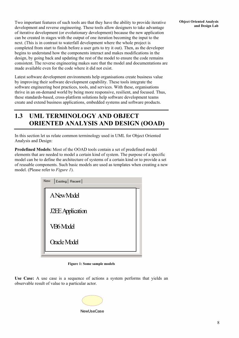
Predefined Models: Most of the OOAD tools contain a set of predefined model elements that are needed to model a certain kind of system. The purpose of a specific model can be to define the architecture of systems of a certain kind or to provide a set of reusable components. Such basic models are used as templates when creating a new model. (Please refer to Figure 1).
A New Model J2EE Application VB6 Model Oracle Model
Figure 1: Some sample models
Use Case: A use case is a sequence of actions a system performs that yields an observable result of value to a particular actor.
NewUseCase

9
Object Oriented Analysis and Design Lab
Actor: An actor represents many things that interact with the system. Actor A class icon is drawn as a 3 part box, with the class name in the top part, a list of attributes (with optional types and values) in the middle part, and a list of operations (with optional argument lists and return types) in the bottom part.
NewClassattribute
operation()
Stereotype: Representing one model element in the form of another model element.
Classes are stereotyped depending on the following categories:
Boundary Class: A boundary class represents an interface between the system and some entity outside the system: a person or another system. Its role is to mediate the exchange of information with the outside world, and to insulate the system from changes in its surroundings. They are of the following types:
• User Interface Classes: Intermediate communication with human users of the system.
• System Interface Classes: Intermediate communication with other system.
• Device Interface Classes: Intermediate communication with external devices.
Boundary Class
Control Class: A control class is a class used to model control behaviour specific to one or a few use cases. Control objects (instances of control classes) often control other objects, so their behavior is of the coordinating type. Control classes encapsulate use-case specific behaviour.
Control Class
Entity Class: An entity class is a class used to model information and associated behavior that must be stored. Entity objects (instances of entity classes) are used to hold and update information about some phenomenon, such as an event, a person, or some real-life object. They are usually persistent, having attributes and relationships needed for a long period, sometimes for the life of the system.
Entity Class
10
Object Oriented Analysis and Design Lab
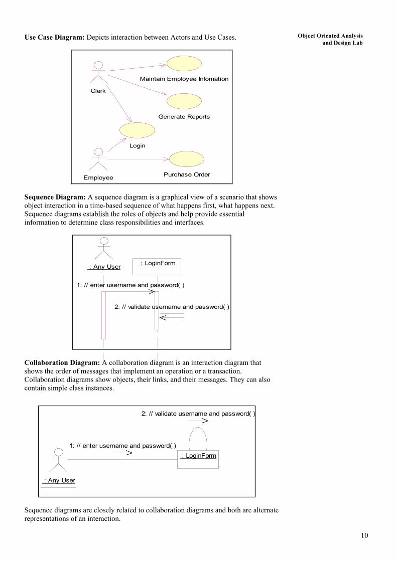
Use Case Diagram: Depicts interaction between Actors and Use Cases.
Maintain Employee Infomation
Purchase Order
Clerk
Generate Reports
Employee
Login
Sequence Diagram: A sequence diagram is a graphical view of a scenario that shows object interaction in a time-based sequence of what happens first, what happens next. Sequence diagrams establish the roles of objects and help provide essential information to determine class responsibilities and interfaces.
: Any User : LoginForm
1: // enter username and password( )
2: // validate username and password( )
Collaboration Diagram: A collaboration diagram is an interaction diagram that shows the order of messages that implement an operation or a transaction. Collaboration diagrams show objects, their links, and their messages. They can also contain simple class instances.
: Any User
: LoginForm
2: // validate username and password( )
1: // enter username and password( )
Sequence diagrams are closely related to collaboration diagrams and both are alternate representations of an interaction.
11
Object Oriented Analysis and Design Lab
Main difference between sequence and collaboration diagrams: sequence diagrams show time-based object interaction while collaboration diagrams show how objects associate with each other.
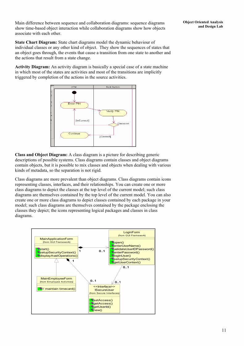
State Chart Diagram: State chart diagrams model the dynamic behaviour of individual classes or any other kind of object. They show the sequences of states that an object goes through, the events that cause a transition from one state to another and the actions that result from a state change.
Activity Diagram: An activity diagram is basically a special case of a state machine in which most of the states are activities and most of the transitions are implicitly triggered by completion of the actions in the source activities.
Class and Object Diagram: A class diagram is a picture for describing generic descriptions of possible systems. Class diagrams contain classes and object diagrams contain objects, but it is possible to mix classes and objects when dealing with various kinds of metadata, so the separation is not rigid.
Class diagrams are more prevalent than object diagrams. Class diagrams contain icons representing classes, interfaces, and their relationships. You can create one or more class diagrams to depict the classes at the top level of the current model; such class diagrams are themselves contained by the top level of the current model. You can also create one or more class diagrams to depict classes contained by each package in your model; such class diagrams are themselves contained by the package enclosing the classes they depict; the icons representing logical packages and classes in class diagrams.
MainEmployeeForm
// maintain timecard()
(from Employee Activities)
ISecureUser
setAccess()getAccess()getUserId()new()
(from Secure Interfaces)
<<Interface>>
MainApplicationForm
start()setupSecurityContext()displayAvailOperations()
(from GUI Framework)
1
0..1
1
0..1
LoginForm
open()enterUserName()validateUserIDPassword()enterPassword()logInUser()setupSecurityContext()getUserContext()
(from GUI Framework)
0..1
0..1
0..1
0..1
1 0..11 0..1

12
Object Oriented Analysis and Design Lab 1.4 A SAMPLE PROBLEM
Let us show the process of OOAD through software tools.
1.4.1 Problem Statement for Railway Reservation System
Software has to be developed for automating the manual railway reservation system. The system should be distributed in nature. It should be designed to provide functionalities as explained below:
1. Reserve Seat: A passenger should be able to reserve seats in the train. A reservation form is filled by the passenger and given to the clerk, who then checks for the availability of seats for the specified date of journey. If seats are available then the entries are made in the system regarding the train name, train number, date of journey, boarding station, destination, person name, sex and total fare. Passenger is asked to pay the required fare and the tickets are printed. If the seats are not available then the passenger is informed.
2. Cancel Reservation: A passenger wishing to cancel a reservation is required to fill a form. The passenger then submits the form and the ticket to the clerk. The clerk then deletes the entries in the system and changes the reservation status of that train. The clerk crosses the ticket by hand to mark as cancelled.
3. Update Train Information: Only the administrator enters any changes related to the train information like change in the train name, train number, train route etc. in the system.
4. Report Generation: Provision for generation of different reports should be given in the system. The system should be able to generate reservation chart, monthly train report etc.
5. Login: For security reasons all the users of the system are given a user id and a password. Only if the id and password are correct is the user allowed entry to the system and select from the options available in the system.
6. View Reservation Status: All the users should be able to see the reservation
status of the train online. The user needs to enter the train number and the pin number printed on his ticket so that the system can display his current reservation status like confirmed, RAC or Wait-listed.
7. View Train Schedule: Provision should be given to see information related to the train schedules for the entire train network. The user should be able to see the train name, train number, boarding and destination stations, duration of journey etc.
1.4.2 Analysis and Design Methodology
The sequences of steps for the process are as follows: Step 1: Choose a pre-designed model if it exists. Choose the framework according to the development platform. Step 2: Make Use of Case Diagram. The general flow of any analysis and design process is to begin with the identification of the functionalities of the system and the actors associated with the system. We depict the overview of the system to be developed by a Use Case diagram.
13
Object Oriented Analysis and Design Lab
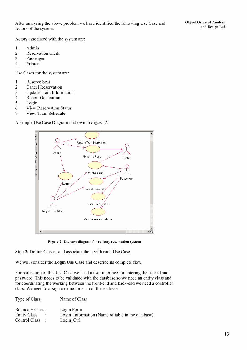
After analysing the above problem we have identified the following Use Case and Actors of the system. Actors associated with the system are:
1. Admin 2. Reservation Clerk 3. Passenger 4. Printer
Use Cases for the system are:
1. Reserve Seat 2. Cancel Reservation 3. Update Train Information 4. Report Generation 5. Login 6. View Reservation Status 7. View Train Schedule
A sample Use Case Diagram is shown in Figure 2:
Figure 2: Use case diagram for railway reservation system Step 3: Define Classes and associate them with each Use Case. We will consider the Login Use Case and describe its complete flow. For realisation of this Use Case we need a user interface for entering the user id and password. This needs to be validated with the database so we need an entity class and for coordinating the working between the front-end and back-end we need a controller class. We need to assign a name for each of these classes. Type of Class Name of Class Boundary Class : Login Form Entity Class : Login_Information (Name of table in the database) Control Class : Login_Ctrl
14
Object Oriented Analysis and Design Lab
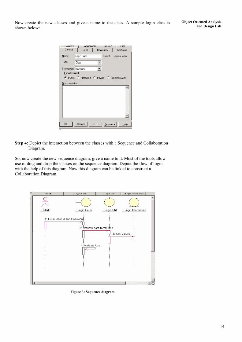
Now create the new classes and give a name to the class. A sample login class is shown below:
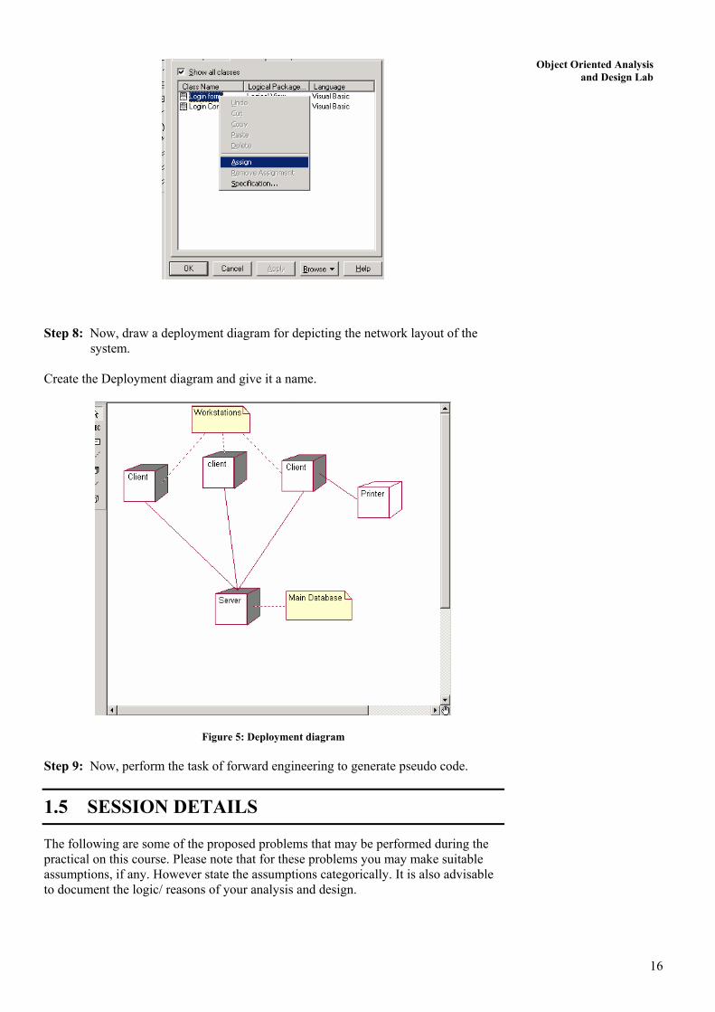
Step 4: Depict the interaction between the classes with a Sequence and Collaboration Diagram. So, now create the new sequence diagram, give a name to it. Most of the tools allow use of drag and drop the classes on the sequence diagram. Depict the flow of login with the help of this diagram. Now this diagram can be linked to construct a Collaboration Diagram.
Figure 3: Sequence diagram

15
Object Oriented Analysis and Design Lab
Figure 4: Collaboration diagram Step 5: Draw Activity Diagram and State Chart Diagram if required. These diagrams should be names and linked to other related diagrams. Step 6: Draw Class Diagram for all the Entity classes depicting relationships between the classes. Attributes are defined for each class. You must give proper names to these diagrams. Mark each class as persistent. They are the database tables where data is to be stored. Step 7: Define the components of the system, for example, exes, dlls, activeX controls etc. Suppose, you wish to develop the software as an executable, so all the boundary and control classes are assigned to the exe. Create an executable software component and give it a name. This component must be assigned to class. Then, draw a component diagram to show the relations between the components of the system. You must give a name to the diagram.
16
Object Oriented Analysis and Design Lab
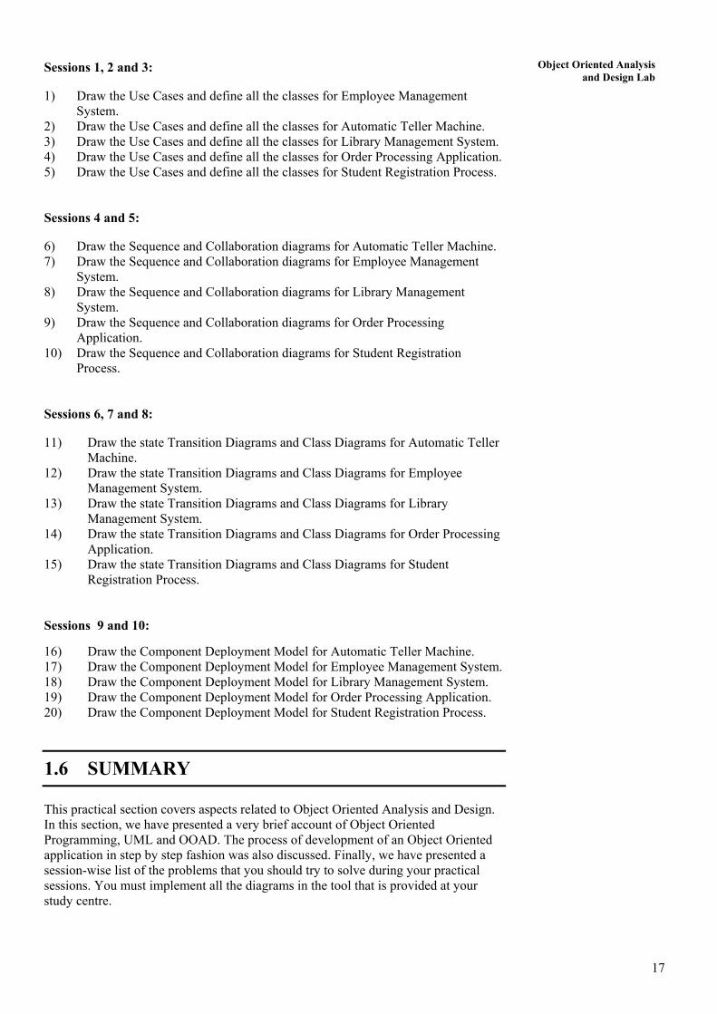
Step 8: Now, draw a deployment diagram for depicting the network layout of the system. Create the Deployment diagram and give it a name.
Figure 5: Deployment diagram Step 9: Now, perform the task of forward engineering to generate pseudo code.
1.5 SESSION DETAILS
The following are some of the proposed problems that may be performed during the practical on this course. Please note that for these problems you may make suitable assumptions, if any. However state the assumptions categorically. It is also advisable to document the logic/ reasons of your analysis and design.
17
Object Oriented Analysis and Design Lab
Sessions 1, 2 and 3:
1) Draw the Use Cases and define all the classes for Employee Management System.
2) Draw the Use Cases and define all the classes for Automatic Teller Machine. 3) Draw the Use Cases and define all the classes for Library Management System. 4) Draw the Use Cases and define all the classes for Order Processing Application. 5) Draw the Use Cases and define all the classes for Student Registration Process. Sessions 4 and 5:
6) Draw the Sequence and Collaboration diagrams for Automatic Teller Machine. 7) Draw the Sequence and Collaboration diagrams for Employee Management
System. 8) Draw the Sequence and Collaboration diagrams for Library Management
System. 9) Draw the Sequence and Collaboration diagrams for Order Processing
Application. 10) Draw the Sequence and Collaboration diagrams for Student Registration
Process. Sessions 6, 7 and 8:
11) Draw the state Transition Diagrams and Class Diagrams for Automatic Teller Machine.
12) Draw the state Transition Diagrams and Class Diagrams for Employee Management System.
13) Draw the state Transition Diagrams and Class Diagrams for Library Management System.
14) Draw the state Transition Diagrams and Class Diagrams for Order Processing Application.
15) Draw the state Transition Diagrams and Class Diagrams for Student Registration Process.
Sessions 9 and 10:
16) Draw the Component Deployment Model for Automatic Teller Machine. 17) Draw the Component Deployment Model for Employee Management System. 18) Draw the Component Deployment Model for Library Management System. 19) Draw the Component Deployment Model for Order Processing Application. 20) Draw the Component Deployment Model for Student Registration Process.
1.6 SUMMARY
This practical section covers aspects related to Object Oriented Analysis and Design. In this section, we have presented a very brief account of Object Oriented Programming, UML and OOAD. The process of development of an Object Oriented application in step by step fashion was also discussed. Finally, we have presented a session-wise list of the problems that you should try to solve during your practical sessions. You must implement all the diagrams in the tool that is provided at your study centre.
Lab M anual SECTION 2: SOFTWARE ENGINEERING LAB
Structure Page Nos.
2.0 Introduction 18 2.1 Objectives 18 2.2 Software Project Management 18 2.3 Working with Requirements 20
2.3.1 Feasibility Report 2.3.2 Software Requirement Specifications
2.4 Design Document 27 2.5 Testing 29 2.6 Implementation 30 2.7 List of Problems 30 2.8 Summary 31
2.0 INTRODUCTION
Software Engineering relates to the process of development of quality software with increasing use of software preparation standards and guidelines. Software is the single most expensive item in a computer system. During the life time of a system about 95% of the cost is incurred on Software and only 5% on hardware. Computer Aided Software Engineering (CASE) tools help in many software engineering tasks with the help of the information created using the computer. CASE tools support software engineering tasks for the different phases of Software Development Life Cycle (SDLC). MCS-034 discusses various aspects of Software Enginerring in detail. You must go through this course before taking the practical in this lab. The practical in this unit revolves around various phases of software development.
This lab is an attempt to help you practice proper software development methodology. You must do these software development activities (lab problems) with the help of suitable tools.
2.1 OBJECTIVES
After going through and working with the problems given in this section, you should be able to:
• visualise SRS in a sample format; • see a sample models that you can draw using diagramming tools; • see a sample of test cases in the desired format; • demonstrate the use of various features of Project Management, and • use software development tools (only after solving the list of problems using suitable tools).
2.2 SOFTWARE PROJECT MANAGEMENT
The software project management tools support project planning and scheduling. Some of the sample information that you can produce using these tools are:
A Sample Partial Project Plan Overall Goal of the Project
18

Software Engineering Lab
The proposed software system should be able to:
• read the structured data available in the Excel files and store it in a Database system.
• validate data of the database on the basis of predefined business rules. • prepare reports on data that is found to be in error during validation. • prepare MIS reports from the validated data. The Primary Data The Primary data in the system is the employee data of the participant companies.
Delivery Deadlines
6 months from the date of Approval.
PROJECT PLAN 1 OBJECTIVES The objective of the system can be defined here as:
• The proposed system should be able to read the data from Excel files and store validated data in the Database.
• ………………………………………. 2 SPECIFIC PRODUCTS TO BE DELIVERED
The products that will be delivered (You need not include all for an actual system):
• The tested system and Network • Clint Workstations • A robust Database Management Server • Any other third party software.
3 ACTIVITIES AND MILESTONES The activities in the system, after including the provisions for security, are:
• Verification of the Users. • Migration of the Excel data. • Validation of the the migrated data. • …………………………………. The milestones in the system are: • Start of the Project : 1st June, 2006 • SRS Completion : 28th June, 2006 • Requiements finalization : 1st July, 2006
• ……………………………………………………
4 RESOURCE REQUIREMENT
The Hardware, Software, and Tools are required for the three different environments, viz., Development environment, Quality Control environment, Deployment environment. These resources may be documented accordingly.
19

Lab Manual 5 SCHEDULING
GANTT Chart
A very elementary Gantt or Timeline Chart for the development plan is given below. The plan explains the tasks versus the time they will take to complete.
PERT Chart
A suitable PERT Chart for the development plan can be given here.
6 BUDGETARY ESTIMATES
The whole budgetary estimates may be divided into resource procurement and software development costs. The software development efforts and cost may be estimated with the help of COCOMO or any other model used by the organisation.
7 Summary Please provide the summary here.
2.3 WORKING WITH REQUIREMENTS Some of the activities that you can do with the help of tools are:
• Cost Estimation • Creation of SRS • Traceability of requirements • Non-ambigouous requirements document • Creation of Models.
Some of the partial samples for some of the above are illustrated here:
2.3.1 Feasibility Report
You may include contents as per the following table. A sample is shown after the table.
Topic Some of the contents of the topic Introduction Include the project background and report layout here. Terms of Reference Define the expectations of the project, the Time Frame and Available
Resources Existing System Define here the results of Fact Finding, working of the Current System and
the problems in the Current System
20
Software Engineering Lab
System Requirements Give here the system requirements after discussion with the System User Proposed System Define the outline of the Proposed System, key Input and Output to and
from the system Development Plan, Cost Feasibility and other feasibilities
You can include the Gantt Chart, Pert Chart, cost estimation, etc.
INTRODUCTION Background of the Project The basic requirement of the user and working of the system are: • The Client should be able to upload the available data in Excel files into the Database. • This data is then validated by the software called VALIDITY CHECKER.
This software contains the basic business rules and also produces error reports
• …………………………………………….
Report Layout Give the information about the layout of the report here. For example, you may include a partial table like (Please do not forget to page number all the contents documents). TERMS OF REFERENCE
What is expected?
The expected system is based on processing the employee data of an organisation. The data is to be stored securely in the database. Statistical manipulations are done on the data to produce reports as desired by the client company.
Time Frame
The delivery deadline for the system is 6 months from the date of start of the project.
What resources are available?
The resources that are available are.
• Personal, however, that needs training. • Linux Operating System. • Systems are Networked. • Servers and reliable Database Management System.
EXISTING SYSTEM
Working of the Current System
You can write this topic only after doing the requirement analysis. You need to gather information with the help of requirement gathering phase which includes interviewing the users, making them fill the questionnaires and referring to the workflows that are currently functioning. In the example we are dealing with, the current system may be:
• read the data from the Excel files and stores it into the database. • validate the data on the basis of business rules and generate reports to
show the errors in data. • correction of data is then performed. • create MIS reports.
Problems in the Current System
The problems of the current system are:
21

Lab Manual • For every data collection cycle new Excel-based system needs to be
developed. • All the functions take a lot of time to complete. • ……………………….
SYSTEM REQUIREMENTS
The following type of requirements now can be quoted:
• The system should be able to read the data from Excel files and store it in the Database.
• ………………….
PROPOSED SYSTEM
Project Outline You may give the outline of the Proposed System here. Explain the terms and data references in the data dictionary.
DATA DICTIONARY Some sample of the terms that are used during the documents :
Name Expansion of Name Where used Additional
Description
CLIENT
In Functional Diagrams and Class Diagrams
This is an Object
Excel Data Files In Class Diagrams This is an Object
Verify username & password In Functional
Diagrams This is a Process
Data Validation In Functional Diagrams This is a Process
Generate Internal Reports In Functional
Diagrams This is a Process
c_number Client Number In Class Diagrams This is an attribute of Client. It is a Unique field
client_name Client Name In Class Diagrams This is an attribute of Client
client_phnumber Client Phone Number In Class Diagrams This is an attribute of
Client
report number Report Number In Class Diagrams This is an attribute of
Report
……….. ………. ……….. ………….
2.3.2 Software Requirement Specifications
Normally IEEE standard is followed. A typical format of SRS is as follows: TABLE OF CONTENTS
Introduction
• Purpose • Scope
22 • Definition
Software Engineering Lab
• Product and its function • Benefits and Goals • Overview.
Overall Description
• Product Description • Product Functioning • Functions of Project • Users of Project • Assumptions made. Specific Requirements
• Interface Requirements • User Requirements • Hardware Requirements • Software Requirements • Logical Database Requirements.
Basic Processing Actions of the System Appendices
• Input/Output Formats • Instruction for Security • Results of Fact Finding • Data Model • Functional Model • Process Specification.
A sample portion of SRS is given below:
INTRODUCTION
Purpose SRS contains details of the proposed software system, sufficient enough for the designers to design the system . Thus, SRS is a means of communicating the findings of the analysis stage to the design stage. The SRS includes .
• Interface • Logical Database • Hardware • Performance and other constraints.
It also contains the assumptions made by the analyst and any systemic dependency.
Scope
The scope of SRS contains all the areas related to the project. The scope of SRS includes.
• Proposed software description • Users of the proposed software • Functional requirements of the software • Assumptions and dependencies in the system • Constraints.
Definition .…………………….. Product and its function ………………………..
23
Lab Manual Benefits and Goals
……………………….. Overview ..………………………
OVERALL DESCRIPTION
Product Description
The Client should be able to upload the raw data in Excel files into the Database. The raw data is then validated using ………
Product Functioning
• The Raw data from the Clients is put into the database. …………………………………………………..
Functions in the Project
There are five functions of the system.
• User Verification
The User is asked to enters the Username and Password. The system checks the validity of Username and Password, otherwise the User is asked to do so again. A maximum of three valid attempts are given to the user.
• Upload Raw Data ………………………. • Validate Data ………………………. • Put the Validated Data ………………………. • Generating Reports …………………………..
Users of the Product ……………………… Assumptions ……………………
SPECIFIC REQUIREMENTS Interface Requirements
The Interface requirements include.
• Easy to follow Interface • Very less graphics • No hidden buttons • Relevant error messages ………………………………. User Requirements
After a careful study of the requirements of the Client, analysts have come up with a set of requirements. …………………………………..
Hardware and Software Requirements
There are three environments that have been created for the project, viz.,
• Development environment • Quality Control environment • Production environment
The hardware requirmemts for all the platforms may be indicated here.
24
Software Engineering Lab
Logical database Requirements
The following information is to be stored in the database:.
• The Clients Raw data • The Clients Validated data • Username and Password.
BASIC PROCESSING ACTIONS OF THE SYSTEM The basic processing actions of the system are.
• Verification of the User ……………………………….. • Upload Data
APPENDICES APPENDIX A
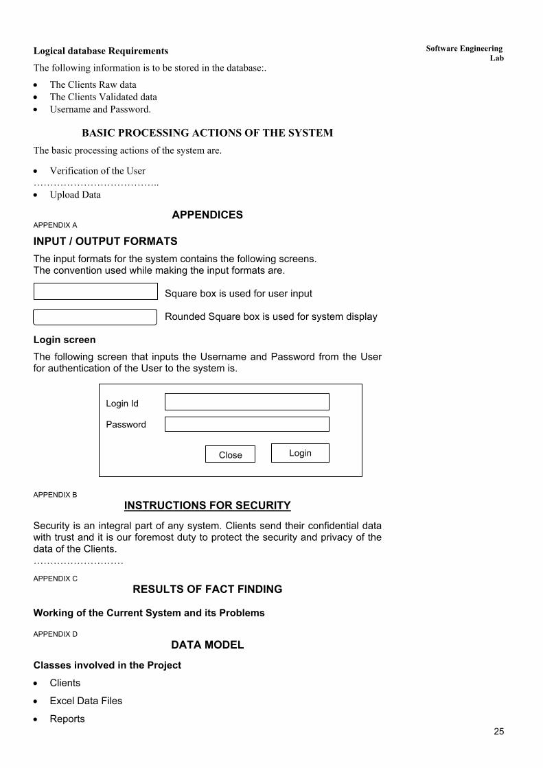
INPUT / OUTPUT FORMATS The input formats for the system contains the following screens. The convention used while making the input formats are. Square box is used for user input
Rounded Square box is used for system display Login screen The following screen that inputs the Username and Password from the User for authentication of the User to the system is.
Close Login
Login Id Password
APPENDIX B
INSTRUCTIONS FOR SECURITY
Security is an integral part of any system. Clients send their confidential data with trust and it is our foremost duty to protect the security and privacy of the data of the Clients. ……………………… APPENDIX C
RESULTS OF FACT FINDING Working of the Current System and its Problems APPENDIX D
DATA MODEL
Classes involved in the Project
• Clients
• Excel Data Files
• Reports 25

Lab Manual Association between the classes
• Clients fill data in the Excel Data Files (M .. M) • Clients generate Reports (M … M)
E-R/Object Diagram for the system
fills data creates
REPORTSEXCEL DATA FILES
CLIENTS
Attributes of the Entities are
Object Classes Attribute Clients number
name address phone number fax email
Excel data Files excel file number client number
Reports report number report name client number
APPENDIX E
FUNCTIONAL MODEL
One sample DFD at level 1 is containing the processes:
• Username and Password verificaiton • Data Migration • Validation of Migrated data • Generate Reports You can make various levels of DFDs
Password & Username OK Raw Data Storage
Username & password
Excel data file
Bad password & username Username &
password verification
Data Migration
Validation
Generate Reports
Reports
Errors and data
Excel data file
Reports
26

Software Engineering Lab
PROCESS SPECIFICATION
Let us give one sample process verification. Process: Username and Password Verification Input: Username & Password Output: Access grant or denied message
Processing The Client enters the Username and Password and clicks the Login button.
The system connects with the DBMS and verifies them in the related database. If both are valid: allow user to enter the system with the allowed access rights for that user. Otherwise prompt wrong Username-Password message and take the user to the screen where s/he can re-enter the Username-Password.
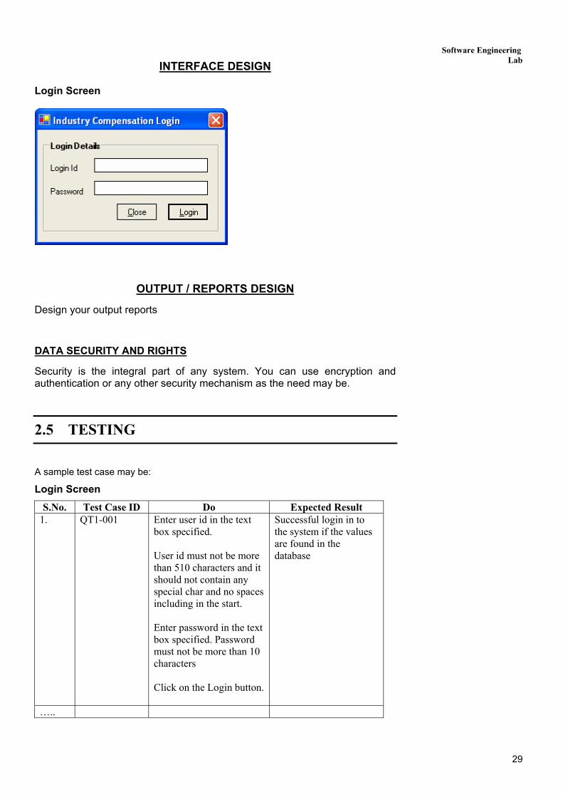
Interface Description
The interface contains the text boxes where the user can enter Username and Password. It also contains a Login button for login and a Close button on closing the application.
Internal Data Structure
The process uses the encrypted username and password table that also contains information about the access permissions.
2.4 DESIGN DOCUMENT
SCOPE Define the System Objectives here ……………………
Architecture Design Give the architecture of the system based on the analysis and flow models.
DATA DESIGN Refine the E-R diagram if needed and make one table for each entry and data store and table for all M.M relationships. For example, the Client table may be: . COLUMN HEADING CONSTRAINTS client_no Primary Key client_number Not Null client_addr Not Null …….
INTERFACE DESIGN Human-Machine Interface Design Rules
Follow the basis rules for the interface design. These can be classified into three main types:
• External Interface design • Interface to the External Data • Interface to the external system or devices External Interface Design
• Easy to follow Interface • Zero or very less graphics as not being used commercially
27
Lab Manual • No hidden buttons
• Proper error messages ……………………………………. Interface to the External Data The system has to use proper external data. The system makes a connection with the DBMS to do so. The rules that have to be followed while interfacing with the external data are:
• You must do the type checking. • Field overrun that is maximum size should be enough to accommodate the
largest data of that type • It is always better to encrypt the data and then store it in the database. Interface to the External System or Device …………………………………..
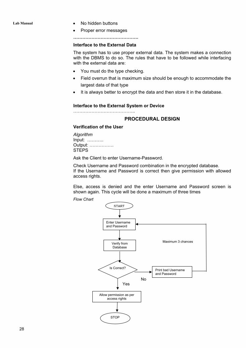
PROCEDURAL DESIGN Verification of the User Algorithm Input: ……….. Output: ……………. STEPS
Ask the Client to enter Username-Password.
Check Username and Password combination in the encrypted database. If the Username and Password is correct then give permission with allowed access rights. Else, access is denied and the enter Username and Password screen is shown again. This cycle will be done a maximum of three times Flow Chart Maximum 3 chances No Yes
STOP
Print bad Username and Password
Allow permission as per access rights
Is Correct?
Verify from Database
Enter Username and Password
START
28
Software Engineering Lab
INTERFACE DESIGN
Login Screen
OUTPUT / REPORTS DESIGN
Design your output reports
DATA SECURITY AND RIGHTS
Security is the integral part of any system. You can use encryption and authentication or any other security mechanism as the need may be.
2.5 TESTING
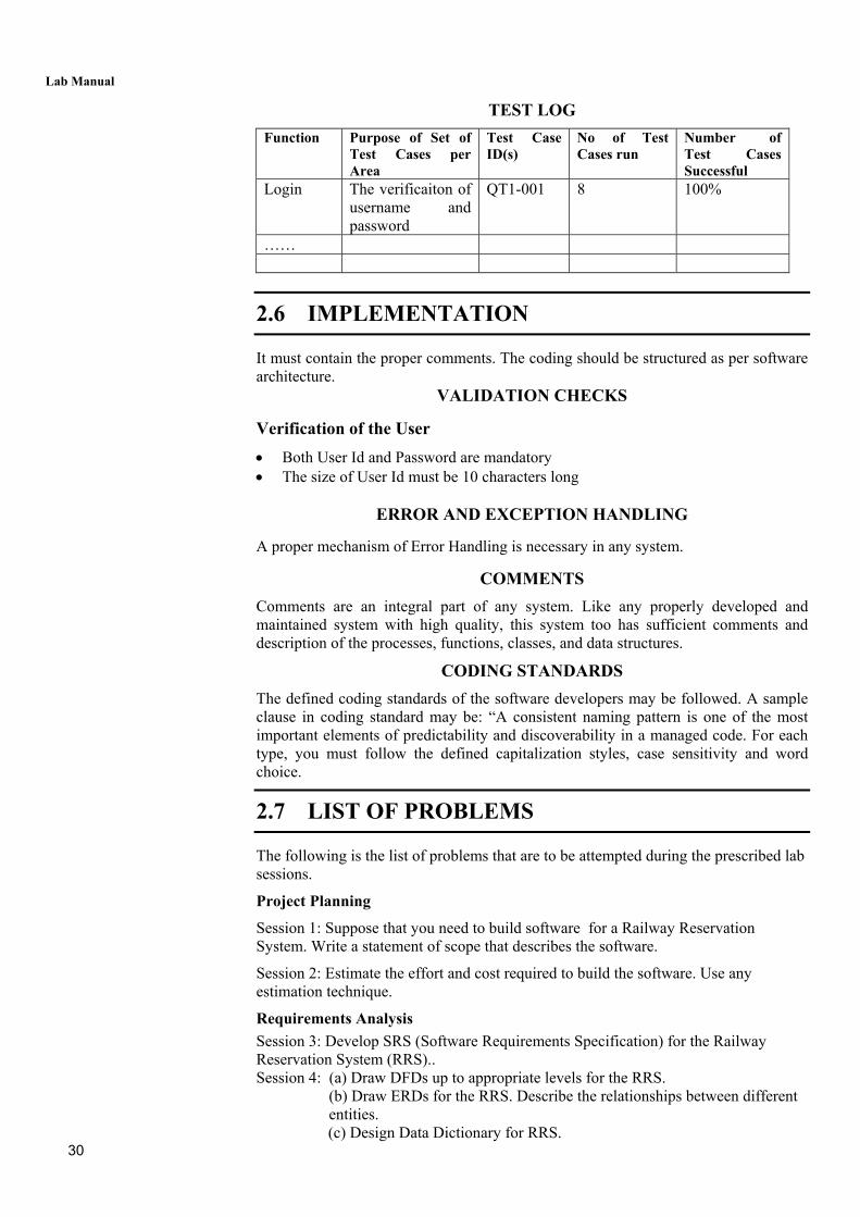
A sample test case may be:
Login Screen S.No. Test Case ID Do Expected Result
1. QT1-001
Enter user id in the text box specified. User id must not be more than 510 characters and it should not contain any special char and no spaces including in the start. Enter password in the text box specified. Password must not be more than 10 characters Click on the Login button.
Successful login in to the system if the values are found in the database
…..
29
Lab Manual
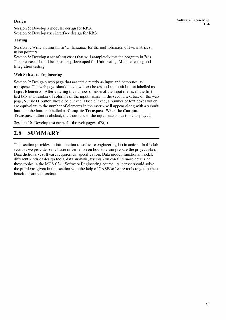
TEST LOG Function Purpose of Set of
Test Cases per Area
Test Case ID(s)
No of Test Cases run
Number of Test Cases Successful
Login The verificaiton of username and password
QT1-001 8 100%
……
2.6 IMPLEMENTATION
It must contain the proper comments. The coding should be structured as per software architecture.
VALIDATION CHECKS
Verification of the User • Both User Id and Password are mandatory • The size of User Id must be 10 characters long
ERROR AND EXCEPTION HANDLING
A proper mechanism of Error Handling is necessary in any system.
COMMENTS Comments are an integral part of any system. Like any properly developed and maintained system with high quality, this system too has sufficient comments and description of the processes, functions, classes, and data structures.
CODING STANDARDS The defined coding standards of the software developers may be followed. A sample clause in coding standard may be: “A consistent naming pattern is one of the most important elements of predictability and discoverability in a managed code. For each type, you must follow the defined capitalization styles, case sensitivity and word choice.
2.7 LIST OF PROBLEMS
The following is the list of problems that are to be attempted during the prescribed lab sessions.
Project Planning
Session 1: Suppose that you need to build software for a Railway Reservation System. Write a statement of scope that describes the software.
Session 2: Estimate the effort and cost required to build the software. Use any estimation technique.
Requirements Analysis Session 3: Develop SRS (Software Requirements Specification) for the Railway Reservation System (RRS).. Session 4: (a) Draw DFDs up to appropriate levels for the RRS.
(b) Draw ERDs for the RRS. Describe the relationships between different entities.
30 (c) Design Data Dictionary for RRS.
31
Software Engineering Lab
Design
Session 5: Develop a modular design for RRS. Session 6: Develop user interface design for RRS.
Testing
Session 7: Write a program in ‘C’ language for the multiplication of two matrices . using pointers. Session 8: Develop a set of test cases that will completely test the program in 7(a). The test case should be separately developed for Unit testing, Module testing and Integration testing.
Web Software Engineering
Session 9: Design a web page that accepts a matrix as input and computes its transpose. The web page should have two text boxes and a submit button labelled as Input Elements . After entering the number of rows of the input matrix in the first text box and number of columns of the input matrix in the second text box of the web page, SUBMIT button should be clicked. Once clicked, a number of text boxes which are equivalent to the number of elements in the matrix will appear along with a submit button at the bottom labelled as Compute Transpose. When the Compute Transpose button is clicked, the transpose of the input matrix has to be displayed.
Session 10: Develop test cases for the web pages of 9(a).
2.8 SUMMARY
This section provides an introduction to software engineering lab in action. In this lab section, we provide some basic information on how one can prepare the project plan, Data dictionary, software requirement specification, Data model, functional model, different kinds of design tools, data analysis, testing.You can find more details on these topics in the MCS-034 : Software Engineering course. A learner should solve the problems given in this section with the help of CASE/software tools to get the best benefits from this section.
Lab Manual
SECTION 3: ACCOUNTANCY AND FINANCIAL MANAGEMENT LAB
Structure Page Nos.
3.0 Introduction 32
3.1 Objectives 32
3.2 Getting Started with Tally 33
3.3 Creating Accounts 35
3.4 Voucher Entry 42
3.5 Report Creation 47
3.6 Practical Session-wise List of Problems 50
3.7 Summary 50
3.0 INTRODUCTION You have already known how to maintain accounts manually. Tally is an accounting package which is used for maintaining your accounts electronically. Following are some general features of Tally: • It maintains all the primary books of accounts, like cashbook and bankbook. • Tally maintains all registers like purchase register, sales registers and journal
registers. • Tally maintains all statement of accounts like Balance Sheet, Profit and Loss and
Trial Balance, Cash Flow and Stock Statement. • A Tally can maintain ‘Outstanding Reports’ • It may provide complete bill-wise information of amounts receivable as well as
payable either party-wise or group-wise. • It can provide a report for a particular date or reports for any range of dates. • It provides the facility of Bank Reconciliation.
3.1 OBJECTIVES
After working with Tally, you should be able to:
• maintain all registers like purchase register, sales register, and journal Register;
• maintain all statements of accounts like Balance Sheet, Profit and Loss Account, and Trial Balance, cash flow, stock statement, and
• produce a wide range of reports.
32

Accountancy and Financial Management Lab
3.2 GETTING STARTED WITH TALLY On the home page of Tally screen ‘Create Company’ option is available under the title ‘Company Info’.
Figure1.1
To create the company you would click at ‘Create Company’ option. A new window will appear with various items on the screen. Some important ones are discussed below:
1. Name: Type the name of the company you want to create. 2. Mailing Name: The mailing name by default is the same as the name mentioned above. You can type some other mailing name of the company. 3. Address: Type mailing address of the company. There is no limit on the number if lines used. 4. Maintain: In Tally accounts can be maintained in a two different ways:
• Accounts Only • Accounts-with-inventory
5. Use Security Control: This option provides security control to your company accounts by offering a comprehensive pass-based access control.
After filling all the required information press enter. A new window will appear asking for confirmation. For acceptance press ‘Y’. The next window is as follow:
33

Lab Manual
Once you get your company created the heading ‘company Info’ has a content of some new options. These options are as follows:
1. Select Company: This option permits you to load any company, which was created earlier, from the list of companies listed.
2. Shut Company: It allows you to exit, from the companies not in use, from the dialog box.
3. Create Company: (same as done above under same heading)
4. Alter: It allows you to change the information of an existing company filled at the time of creation of the company.
5. Change Tally Vault: To change the password, given earlier at the time of creating the company.
6. Split Company Data: Split the companies to form two companies out of the existing one; after the data specify by the user. In this process the closing balance of the first company will become the opening balance of the second company.
7. Backup/ Restore: This option allows the user to take a backup either on local hard disk or on any external media. The backup of one or more companies can be taken under a single directory.
Role of Buttons
The right hand screen area of Tally contains buttons; they perform various useful functions such as:
F1: Select Cmp ─ It enables user to select company(s) and add them to the list of active companies.
F1: Shut Cmp ─ It enables the user to shut or exit the selected company from the list of active companies list.
F11: Features ─ This enables user to set some options related to:
1. Company features
2. Accounting Features
3. Inventory Features
34
Accountancy and Financial Management Lab
Exercise 1:
Q1. Try to open two or more companies with different names. Q2. Show the role of Buttons. Q3. Put meaningful information into all the options available under heading ‘Company Info’.
3.3 CREATING ACCOUNTS
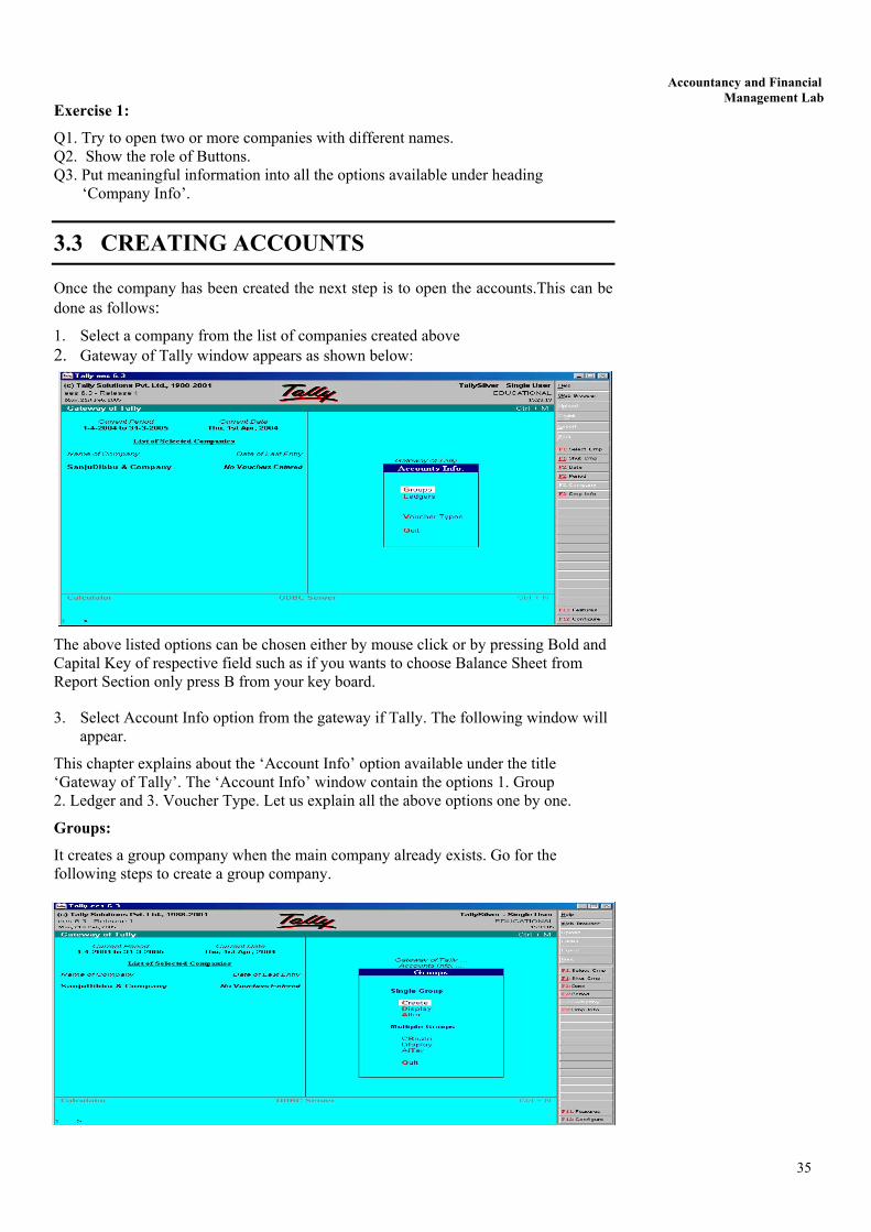
Once the company has been created the next step is to open the accounts.This can be done as follows: 1. Select a company from the list of companies created above 2. Gateway of Tally window appears as shown below:
The above listed options can be chosen either by mouse click or by pressing Bold and Capital Key of respective field such as if you wants to choose Balance Sheet from Report Section only press B from your key board.
3. Select Account Info option from the gateway if Tally. The following window will appear.
This chapter explains about the ‘Account Info’ option available under the title ‘Gateway of Tally’. The ‘Account Info’ window contain the options 1. Group 2. Ledger and 3. Voucher Type. Let us explain all the above options one by one.
Groups:
It creates a group company when the main company already exists. Go for the following steps to create a group company.
35
Lab Manual
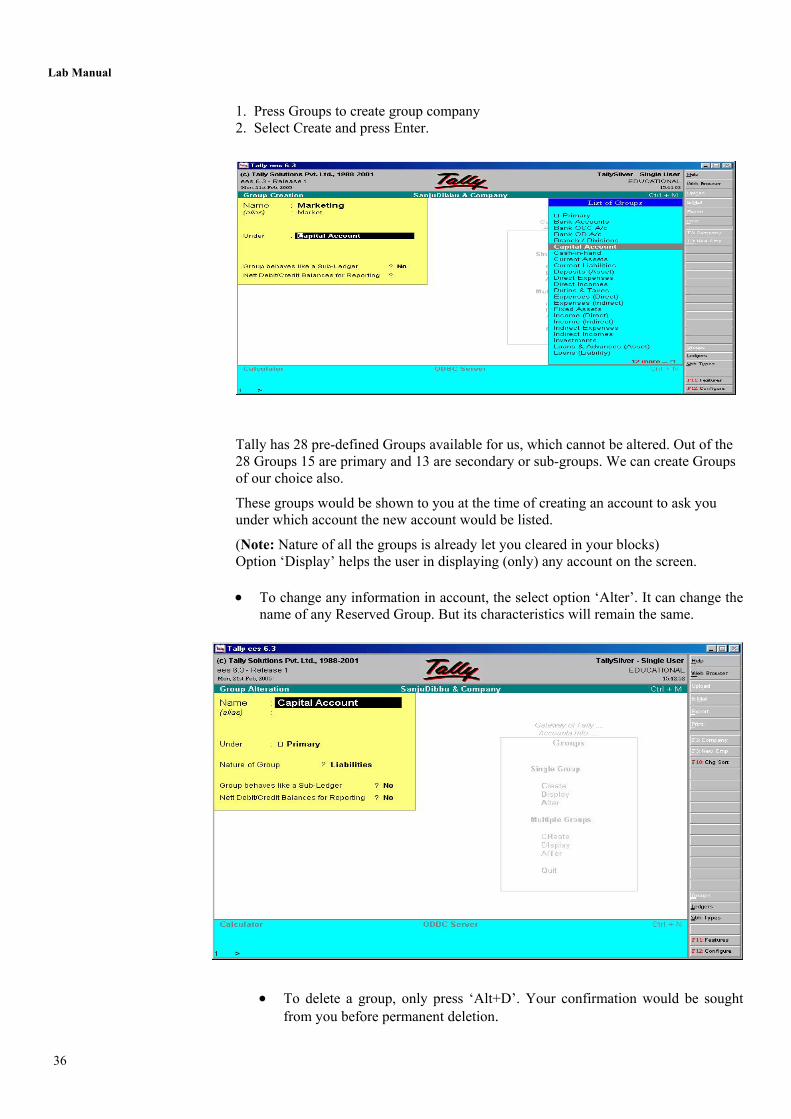
1. Press Groups to create group company 2. Select Create and press Enter.
Tally has 28 pre-defined Groups available for us, which cannot be altered. Out of the 28 Groups 15 are primary and 13 are secondary or sub-groups. We can create Groups of our choice also.
These groups would be shown to you at the time of creating an account to ask you under which account the new account would be listed.
(Note: Nature of all the groups is already let you cleared in your blocks) Option ‘Display’ helps the user in displaying (only) any account on the screen. • To change any information in account, the select option ‘Alter’. It can change the
name of any Reserved Group. But its characteristics will remain the same.
• To delete a group, only press ‘Alt+D’. Your confirmation would be sought from you before permanent deletion.
36
Accountancy and Financial Management Lab
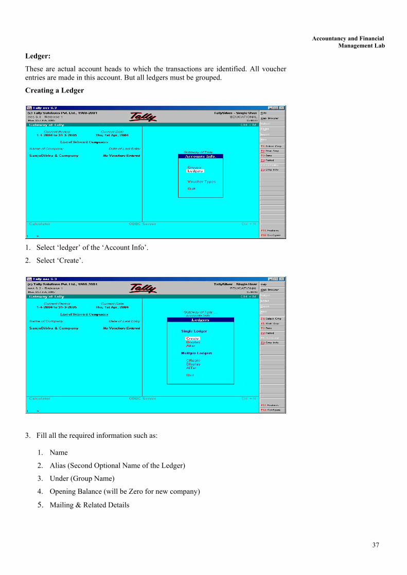
Ledger:
These are actual account heads to which the transactions are identified. All voucher entries are made in this account. But all ledgers must be grouped.
Creating a Ledger
1. Select ‘ledger’ of the ‘Account Info’.
2. Select ‘Create’.
3. Fill all the required information such as:
1. Name
2. Alias (Second Optional Name of the Ledger)
3. Under (Group Name)
4. Opening Balance (will be Zero for new company)
5. Mailing & Related Details
37

Lab Manual
You can display any ledger account on the screen by selecting ‘Display’ from the menu. ‘Alteration’ of group account allows you to change information in account format. You can change the name of any group, but cannot change its characteristics. You can delete a ledger by pressing ‘Alt+D’ in the ledger ‘Alteration screen’. Your confirmation would be sought before permanent deletion. Let us create the ledger of the following transactions.
2004
April 1
,, 2
,, 3
,, 5
,, 8
,, 16
,, 24
,, 28
,, 30
,, 30
Mohan started business with cash
Deposit in the bank
Furniture purchased for cash
Purchased goods for cash
Purchased goods from M/s Ram Narain on credit
Goods sold to M/s Ram & Co. for cash
Goods sold on credit to Ramesh
Received cash from Ramesh
Paid Rent
Paid Salary
Rs.
5000
500
200
400
1000
600
300
300
100
200
In the first transaction we have two accounts - one is real, Cash Account, and the other is Personal, Ram’s Capital Account, so there is a need to open two ledgers but the cash ledger is already available by default, so now there is a need only to open second ledger
Steps:
1. Come to ‘Gateway of Tally’
2. Select ‘Accounts Info’
3. Select Ledgers
4. Select Create
5. Type ‘Ram’s Capital Account’
6. Press <Enter>
7. Select Capital account option from the ‘List of Groups’ under option ‘Under’.
38
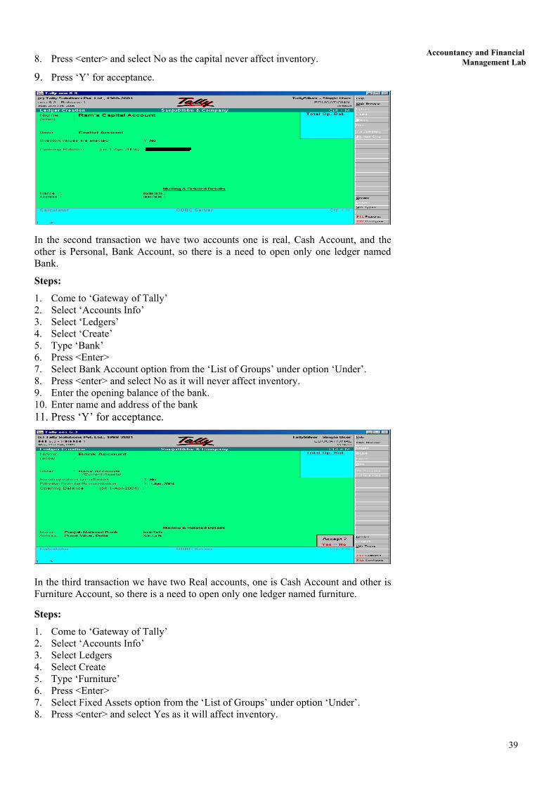
Accountancy and Financial Management Lab 8. Press <enter> and select No as the capital never affect inventory.
9. Press ‘Y’ for acceptance.
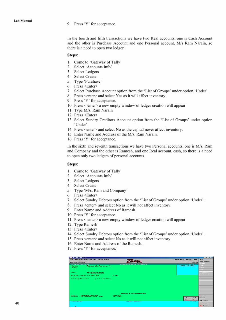
In the second transaction we have two accounts one is real, Cash Account, and the other is Personal, Bank Account, so there is a need to open only one ledger named Bank.
Steps:
1. Come to ‘Gateway of Tally’ 2. Select ‘Accounts Info’ 3. Select ‘Ledgers’ 4. Select ‘Create’ 5. Type ‘Bank’ 6. Press <Enter> 7. Select Bank Account option from the ‘List of Groups’ under option ‘Under’. 8. Press <enter> and select No as it will never affect inventory. 9. Enter the opening balance of the bank. 10. Enter name and address of the bank 11. Press ‘Y’ for acceptance.
In the third transaction we have two Real accounts, one is Cash Account and other is Furniture Account, so there is a need to open only one ledger named furniture.
Steps:
1. Come to ‘Gateway of Tally’ 2. Select ‘Accounts Info’ 3. Select Ledgers 4. Select Create 5. Type ‘Furniture’ 6. Press <Enter> 7. Select Fixed Assets option from the ‘List of Groups’ under option ‘Under’. 8. Press <enter> and select Yes as it will affect inventory.
39
40
Lab Manual 9. Press ‘Y’ for acceptance. In the fourth and fifth transactions we have two Real accounts, one is Cash Account and the other is Purchase Account and one Personal account, M/s Ram Narain, so there is a need to open two ledger.
Steps:
1. Come to ‘Gateway of Tally’ 2. Select ‘Accounts Info’ 3. Select Ledgers 4. Select Create 5. Type ‘Purchase’ 6. Press <Enter> 7. Select Purchase Account option from the ‘List of Groups’ under option ‘Under’. 8. Press <enter> and select Yes as it will affect inventory. 9. Press ‘Y’ for acceptance. 10. Press < enter> a new empty window of ledger creation will appear 11. Type M/s. Ram Narain 12. Press <Enter> 13. Select Sundry Creditors Account option from the ‘List of Groups’ under option
‘Under’. 14. Press <enter> and select No as the capital never affect inventory. 15. Enter Name and Address of the M/s. Ram Narain. 16. Press ‘Y’ for acceptance.
In the sixth and seventh transactions we have two Personal accounts, one is M/s. Ram and Company and the other is Ramesh, and one Real account, cash, so there is a need to open only two ledgers of personal accounts.
Steps:
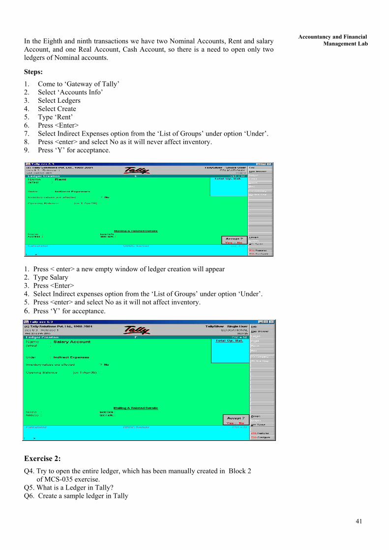
1. Come to ‘Gateway of Tally’ 2. Select ‘Accounts Info’ 3. Select Ledgers 4. Select Create 5. Type ‘M/s. Ram and Company’ 6. Press <Enter> 7. Select Sundry Debtors option from the ‘List of Groups’ under option ‘Under’. 8. Press <enter> and select No as it will not affect inventory. 9. Enter Name and Address of Ramesh. 10. Press ‘Y’ for acceptance. 11. Press < enter> a new empty window of ledger creation will appear 12. Type Ramesh 13. Press <Enter> 14. Select Sundry Debtors option from the ‘List of Groups’ under option ‘Under’. 15. Press <enter> and select No as it will not affect inventory. 16. Enter Name and Address of the Ramesh. 17. Press ‘Y’ for acceptance.
Accountancy and Financial Management Lab In the Eighth and ninth transactions we have two Nominal Accounts, Rent and salary
Account, and one Real Account, Cash Account, so there is a need to open only two ledgers of Nominal accounts.
Steps:
1. Come to ‘Gateway of Tally’ 2. Select ‘Accounts Info’ 3. Select Ledgers 4. Select Create 5. Type ‘Rent’ 6. Press <Enter> 7. Select Indirect Expenses option from the ‘List of Groups’ under option ‘Under’. 8. Press <enter> and select No as it will never affect inventory. 9. Press ‘Y’ for acceptance.
1. Press < enter> a new empty window of ledger creation will appear 2. Type Salary 3. Press <Enter> 4. Select Indirect expenses option from the ‘List of Groups’ under option ‘Under’. 5. Press <enter> and select No as it will not affect inventory. 6. Press ‘Y’ for acceptance.
Exercise 2: Q4. Try to open the entire ledger, which has been manually created in Block 2 of MCS-035 exercise. Q5. What is a Ledger in Tally? Q6. Create a sample ledger in Tally
41
Lab Manual
Q7. Open a ledger named Purchase and then delete it. Q8. Change the name of ledger from Purchase to Sales.
3.4 VOUCHER ENTRY In accounting, vouchers are the main input besides the opening balances which you put in the masters. The output is the form of Reports. Tally recognises a number of vouchers, which can be used to enter the first information of the transaction.
Vouchers are of different types. Some of them are already defined in the Tally programme. Some of the general vouchers are as follows:
• Sales Voucher • Purchase Voucher • Payment Voucher • Receipt Voucher • Journal Voucher
You are all familiar with the names of the above vouchers. Other than the predefined vouchers of the Tally software, users can create vouchers of their own desire and requirement also.
Voucher Entry
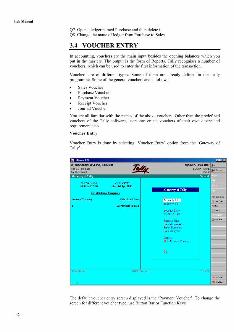
Voucher Entry is done by selecting ‘Voucher Entry’ option from the ‘Gateway of Tally’.
The default voucher entry screen displayed is the ‘Payment Voucher’. To change the screen for different voucher type, use Button Bar or Function Keys.
42
Accountancy and Financial Management Lab
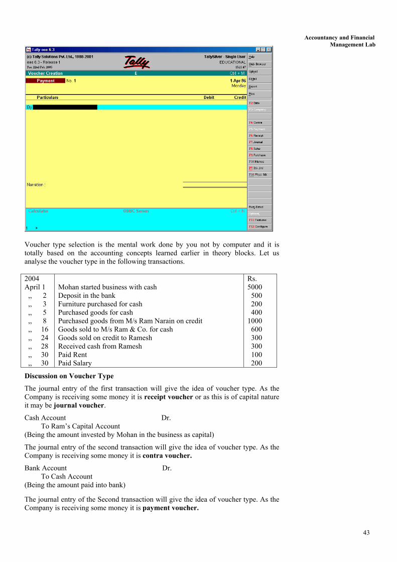
Voucher type selection is the mental work done by you not by computer and it is totally based on the accounting concepts learned earlier in theory blocks. Let us analyse the voucher type in the following transactions. 2004 April 1 ,, 2 ,, 3 ,, 5 ,, 8 ,, 16 ,, 24 ,, 28 ,, 30 ,, 30
Mohan started business with cash Deposit in the bank Furniture purchased for cash Purchased goods for cash Purchased goods from M/s Ram Narain on credit Goods sold to M/s Ram & Co. for cash Goods sold on credit to Ramesh Received cash from Ramesh Paid Rent Paid Salary
Rs. 5000 500 200 400 1000 600 300 300 100 200
Discussion on Voucher Type
The journal entry of the first transaction will give the idea of voucher type. As the Company is receiving some money it is receipt voucher or as this is of capital nature it may be journal voucher.
Cash Account Dr. To Ram’s Capital Account (Being the amount invested by Mohan in the business as capital)
The journal entry of the second transaction will give the idea of voucher type. As the Company is receiving some money it is contra voucher.
Bank Account Dr. To Cash Account (Being the amount paid into bank)
The journal entry of the Second transaction will give the idea of voucher type. As the Company is receiving some money it is payment voucher.
43
Lab Manual
Furniture Account Dr. To Cash Account (Being furniture purchased for cash)
The Tally package will ask for some details of purchased furniture. The new window is as follow:
The journal entry of the Second transaction will give the idea of voucher type. As the Company is receiving some money it is purchase voucher.
Purchases Account Dr. To Cash Account (Being goods purchased for cash)
The journal entry of the Second transaction will give the idea of voucher type. As the Company is receiving some money it is purchase voucher.
Purchases Account Dr. To M/s Ram Narain (Being goods purchased for cash)
The journal entry of the Second transaction will give the idea of voucher type. As the Company is receiving some money it is sales voucher.
Cash Account Dr. To Sales Account (Being goods sold for cash)
The journal entry of the Second transaction will give the idea of voucher type. As the Company is receiving some money it is sales voucher.
Ramesh Dr. To Sales Account (Being goods sold to Ramesh on credit)
The journal entry of the Second transaction will give the idea of voucher type. As the Company is receiving some money it is receipt voucher.
Cash Account Dr. To Ramesh (Being cash received from Ramesh)
The journal entry of the Second transaction will give the idea of voucher type. As the Company is receiving some money it is payment voucher.
Rent Account Dr. To Cash Account (Being Rent paid)
The journal entry of the Second transaction will give the idea of voucher type. As the Company is receiving some money it is payment voucher.
Salary Account Dr. To Cash Account (Being salary paid)
The process of entering the above voucher is as follows:
First Voucher Entry: Receipt Voucher
Cash Account Dr. To Capital Account (Being the amount invested by Mohan in the business as capital)
1. Come to Gateway of Tally 2. Select Voucher Entry either by clicking by mouse or by pressing ‘V’
44
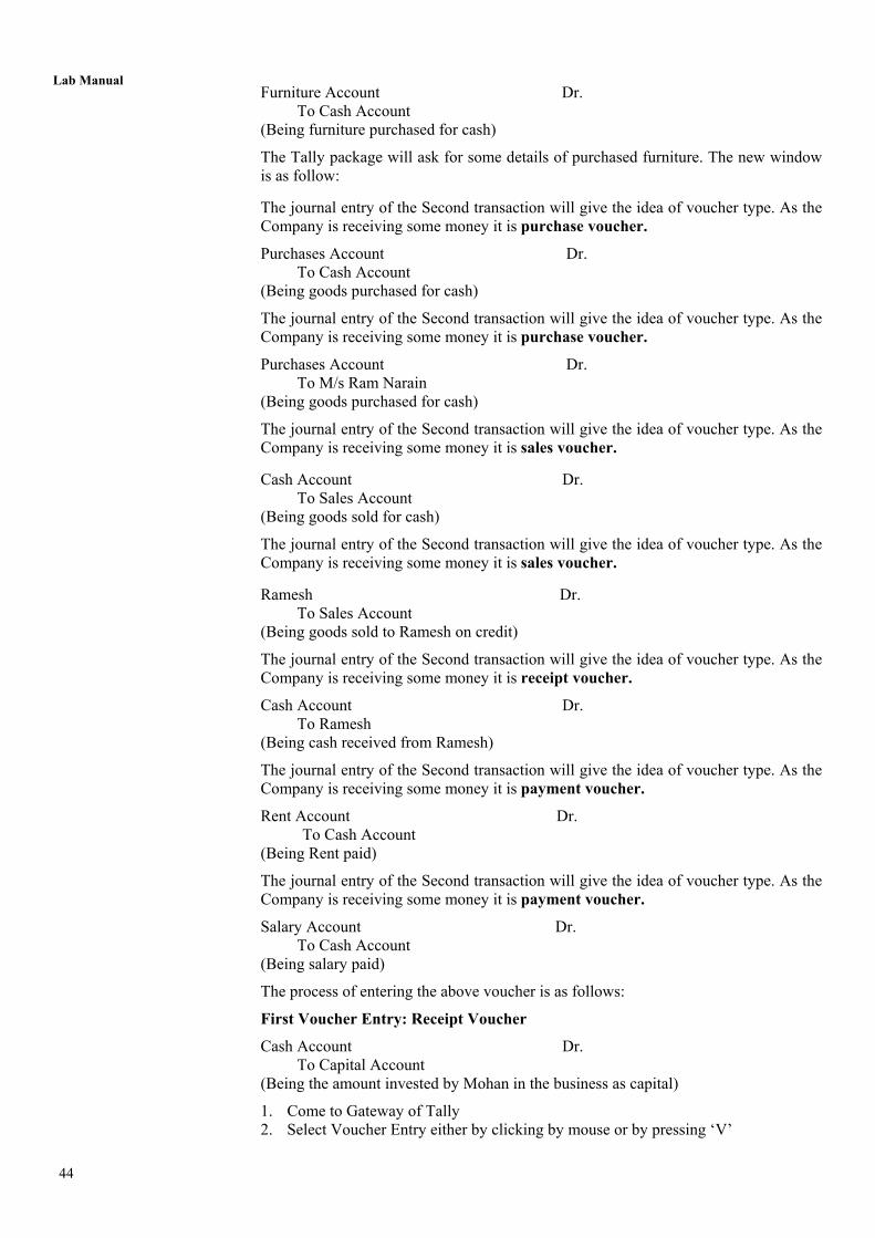
Accountancy and Financial Management Lab 3. Following window with default voucher type ‘Payment Voucher’ will appear.
4. Select F6 button from button bar or press F6 from keyboard the type of voucher change from payment voucher to receipt voucher.
5. Following window of ‘Receipt Voucher’ will appear. 6. In front of ‘To’ write ‘R’ a list of related ledger will appear, select the Ram’s
capital option. 7. Enter the amount Rs.5000 in credit 8. Press Enter 9. The ‘By’ Column will appear, write ‘C’ a list of related ledger will appear select
the cash option, the same amount automatically gets entered in debit column. 10. The voucher screen will appear as follow:
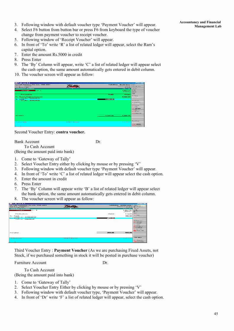
Second Voucher Entry: contra voucher.
Bank Account Dr. To Cash Account (Being the amount paid into bank)
1. Come to ‘Gateway of Tally’ 2. Select Voucher Entry either by clicking by mouse or by pressing ‘V’ 3. Following window with default voucher type ‘Payment Voucher’ will appear. 4. In front of ‘To’ write ‘C’ a list of related ledger will appear select the cash option. 5. Enter the amount in credit 6. Press Enter 7. The ‘By’ Column will appear write ‘B’ a list of related ledger will appear select
the bank option, the same amount automatically gets entered in debit column. 8. The voucher screen will appear as follow:
Third Voucher Entry : Payment Voucher (As we are purchasing Fixed Assets, not Stock, if we purchased something in stock it will be posted in purchase voucher)
Furniture Account Dr.
To Cash Account (Being the amount paid into bank)
1. Come to ‘Gateway of Tally’ 2. Select Voucher Entry Either by clicking by mouse or by pressing ‘V’ 3. Following window with default voucher type, ‘Payment Voucher’ will appear. 4. In front of ‘Dr’ write ‘F’ a list of related ledger will appear, select the cash option.
45
Lab Manual
5. A new window will also appear, asking for detail of furniture purchased with amount.
6. Enter the amount in debit 7. Press Enter 8. The ‘By’ Column will appear, write ‘C’ a list of related ledger will appear select
the cash option, the same amount automatically gets entered in debit column.
The voucher screen will appear as follows:
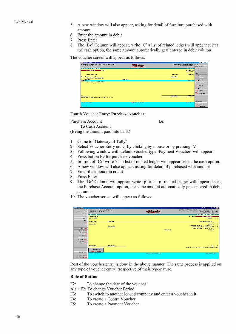
Fourth Voucher Entry: Purchase voucher.
Purchase Account Dr. To Cash Account (Being the amount paid into bank) 1. Come to ‘Gateway of Tally’ 2. Select Voucher Entry either by clicking by mouse or by pressing ‘V’ 3. Following window with default voucher type ‘Payment Voucher’ will appear. 4. Press button F9 for purchase voucher 5. In front of ‘Cr’ write ‘C’ a list of related ledger will appear select the cash option. 6. A new window will also appear, asking for detail of purchased with amount 7. Enter the amount in credit 8. Press Enter 9. The ‘Dr’ Column will appear, write ‘p’ a list of related ledger will appear, select
the Purchase Account option, the same amount automatically gets entered in debit column.
10. The voucher screen will appear as follows:
Rest of the voucher entry is done in the above manner. The same process is applied on any type of voucher entry irrespective of their type/nature.
Role of Button
F2: To change the date of the voucher Alt + F2: To change Voucher Period F3: To switch to another loaded company and enter a voucher in it. F4: To create a Contra Voucher F5: To create a Payment Voucher
46
Accountancy and Financial Management Lab F6: To create a Receipt Voucher
F7: To create Journal Note such as Debit and Credit Notes F8: To create Sales Voucher F9: To create Purchase Voucher F10: To Reverse Journal Voucher and also To create Memorandum Post Dated: To make the current voucher Post-Dated Optional : To mark the current voucher Optional F11: To change the features Exercise 3
Q9. Make voucher entry of the questions which have been manually created by us in Block-2 of MCS-035 exercise. Q10. What do you under stand by Voucher? Q11. Show the use of all the Voucher types available with Tally Q12. Change the date of voucher entered. Q13. Change the period of voucher entered.
3.5 REPORT CREATION
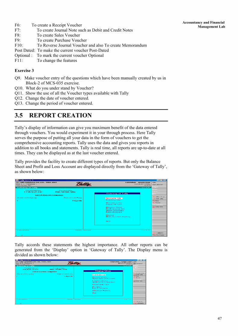
Tally’s display of information can give you maximum benefit of the data entered through vouchers. You would experiment it in your through process. Here Tally serves the purpose of putting all your data in the form of vouchers to get the comprehensive accounting reports. Tally uses the data and gives you reports in addition to all books and statements. Tally is real time, all reports are up-to-date at all times. They can be displayed as at the last voucher entered.
Tally provides the facility to create different types of reports. But only the Balance Sheet and Profit and Loss Account are displayed directly from the ‘Gateway of Tally’, as shown below:
Tally accords these statements the highest importance. All other reports can be generated from the ‘Display’ option in ‘Gateway of Tally’. The Display menu is divided as shown below:
47

Lab Manual
As you can see from the menu, Displays are roughly organised into ‘Accounts information’ displays and ‘Inventory information’ displays – conforming to the two major areas of operation. Each area is grouped separately into books and statements.
Books of account record the individual transaction details you have entered through vouchers. Although you may post items to many different ledgers, Tally brings all the transactions of one category together into a book of accounts for viewing and printing. For example, the cash book records all the transactions affecting cash, the sales book records all the sales transactions.
Financial statements on the other hand are still derived from individual transactions but tend to show summary totals, ratios and statistics, analysing a company’s financial data in a wide variety of ways. Typical financial statements include the Balance Sheet, Profit and Loss Account and Cash Flow Analysis. Financial statements are usually statutory requirements in most countries.
In each case, when you display a report, you can step down to the next level of detail by highlighting the item and pressing <enter> and you can keep going until you reach an individual voucher. Similarly, you can step back to higher levels by pressing (Esc). The special features available for the currently displayed report are indicated on the button bar and can be selected with a single click of the mouse.
All books are displayed first as a monthly summary with opening and closing balances. To display all the transaction of a month select the particular month and then press <enter>. The opening and closing balances as well as transactions totals are also displayed. You can see the voucher by selecting the transaction. This voucher comes up either in display or in alteration mode depending upon the access rights available to you.
Display Balance Sheet
As you already know, the Balance Sheet gives the state of the financial affairs of a company on a given date. It lists the Assets and Liabilities based on the Primary Groups of Tally. The Balance Sheet in Tally is updated instantly with every transaction voucher that is entered and saved. No special processing is required to produce a Balance Sheet.
Steps:
1. Select Gateway of Tally 2. Select Balance Sheet
You will get the Horizontal form of Balance Sheet. You may have the vertical form of the Balance sheet by selecting it from F12: Configuration. Different information can be extracted by using various buttons in Button Bar, such as by using F2 you can change the period of the Balance Sheet.
NOTE: The above figure in the profit and loss account depends only upon the figure mentioned in trial balance. You can change the period of the Profit and Loss Account.
48
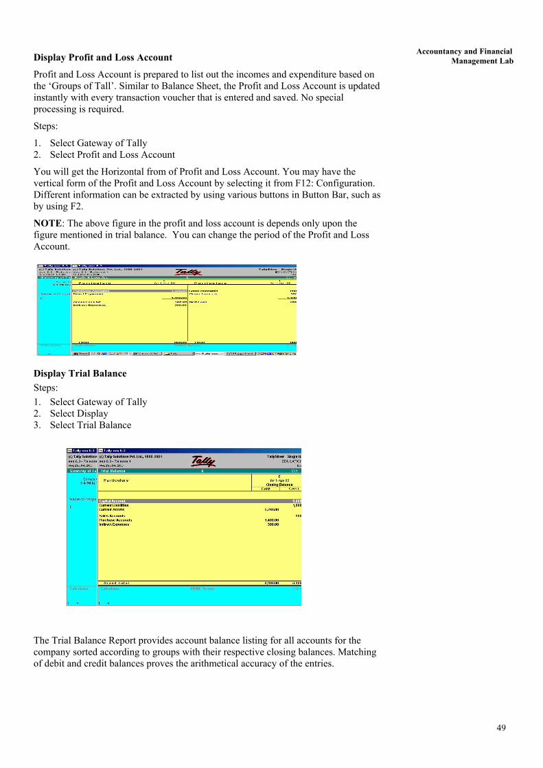
Accountancy and Financial Management Lab Display Profit and Loss Account
Profit and Loss Account is prepared to list out the incomes and expenditure based on the ‘Groups of Tall’. Similar to Balance Sheet, the Profit and Loss Account is updated instantly with every transaction voucher that is entered and saved. No special processing is required.
Steps:
1. Select Gateway of Tally 2. Select Profit and Loss Account
You will get the Horizontal from of Profit and Loss Account. You may have the vertical form of the Profit and Loss Account by selecting it from F12: Configuration. Different information can be extracted by using various buttons in Button Bar, such as by using F2.
NOTE: The above figure in the profit and loss account is depends only upon the figure mentioned in trial balance. You can change the period of the Profit and Loss Account.
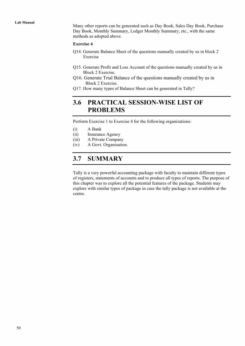
Display Trial Balance Steps: 1. Select Gateway of Tally 2. Select Display 3. Select Trial Balance
The Trial Balance Report provides account balance listing for all accounts for the company sorted according to groups with their respective closing balances. Matching of debit and credit balances proves the arithmetical accuracy of the entries.
49
Lab Manual
Many other reports can be generated such as Day Book, Sales Day Book, Purchase Day Book, Monthly Summary, Ledger Monthly Summary, etc., with the same methods as adopted above.
Exercise 4
Q14. Generate Balance Sheet of the questions manually created by us in block 2 Exercise Q15. Generate Profit and Loss Account of the questions manually created by us in Block 2 Exercise. Q16. Generate Trial Balance of the questions manually created by us in Block 2 Exercise. Q17. How many types of Balance Sheet can be generated in Tally?
3.6 PRACTICAL SESSION-WISE LIST OF PROBLEMS Perform Exercise 1 to Exercise 4 for the following organizations:
(i) A Bank (ii) Insurance Agency (iii) A Private Company (iv) A Govt. Organisation.
3.7 SUMMARY Tally is a very powerful accounting package with faculty to maintain different types of registers, statements of accounts and to produce all types of reports. The purpose of this chapter was to explore all the potential features of the package. Students may explore with similar types of package in case the tally package is not available at the centre.
50

51
Accountancy and Financial Management Lab
