mcrp 3-17b engineer forms and reports - marines.mil 3-17b engineer forms... · mcrp 3-17b engineer...
TRANSCRIPT

MCRP 3-17B
Engineer Forms and Reports
U.S. Marine Corps
PCN 144 000032 00

DEPARTMENT OF THE NAVYHeadquarters United States Marine Corps
Washington, DC 20380-1775
3 October 1997
FOREWORD
Marine Corps Reference Publication (MCRP) 3-17B, Engineer Forms and Reports,provides Marine air-ground task force (MAGTF) engineers with authoritative formatsof engineer-related reports, annexes, appendices, tabs, and enclosures normallyrequired in operation plans and orders. This publication complements Fleet MarineForce Manual (FMFM) 13, MAGTF Engineer Operations, and provides a completefoundation for the execution of engineer operations. The primary target audience is allengineers responsible for executing and reporting engineer support to the MAGTF.
Reviewed and approved this date. BY DIRECTION OF THE COMMANDANT OF THE MARINE CORPS
J. E. RHODES Lieutenant General, U.S. Marine Corps
Commanding GeneralMarine Corps Combat Development Command
DISTRIBUTION: 144 000032 00

To Our Readers
Changes: Readers of this publication are encouraged to submit suggestions and changes thatwill improve it. Recommendations may be sent directly to Commanding General, Doctrine Di-vision (C 42), Marine Corps Combat Development Command, 3300 Russell Road, Suite318A, Quantico, VA 22134-5021 or by fax to 703-784-2917 (DSN 278-2917) or by E-mail tosmb@doctrine div@mccdc. Recommendations should include the following information:
Location of changePublication number and titleCurrent page numberParagraph number (if applicable)Line numberFigure or table number (if applicable)
Nature of changeAdd, deleteProposed new text, preferably double-spaced and typewritten
Justification and/or source of change
Additional copies: A printed copy of this publication may be obtained from Marine CorpsLogistics Base, Albany, GA 31704-5001, by following the instructions in MCBul 5600, MarineCorps Doctrinal Publications Status. An electronic copy may be obtained from the DoctrineDivision, MCCDC, world wide web home page which is found at the following universal refer-ence locator: http://ismo-www1.quantico.usmc.mil/docdiv.
Unless otherwise stated, whenever the masculine or feminine gender is used, both men and women are included.

TABLE OF CONTENTS
PageSECTION 1 GENERAL
Daily Engineer Situation Report 1-2Fragmentary Engineer Situation Report 1-4Engineer Equipment Report 1-4Engineer Reconnaissance Instructions 1-5Engineer Reconnaissance Report, DA Form 1711-R 1-7Enemy Stores and Equipment Report 1-9Installation Report 1-9Local Resources Report 1-9Terrain Report 1-10Water Point Report 1-10
SECTION 2 MOBILITY
Airfield Report 2-2Air Landing Area Report 2-2Airstrip Report 2-3Amphibious Crossing Site Report 2-3Classification Bridge Assessment Summary Form 2-4Breach Comparison 2-5Bridge Reconnaissance Report, DA Form 1249 2-6Bridge Report 2-8Bridge Site Report 2-8Combat Route Site Report 2-9Dam and Sluice Report 2-9Demolition Reconnaissance Record, DA Form 2203-R 2-10Enemy Demolitions Report 2-12Enemy and/or Unidentified Minefield Report 2-12Ferry Reconnaissance Report, DA Form 1252 2-13Ferry Site Report 2-15Ford Report 2-15Ford Reconnaissance Report, DA Form 1251 2-16Obstacle Report 2-18Port Report 2-18Road(s) Closed Report 2-19Road(s) Opened Report 2-19Road Reconnaissance Report, DA Form 1248 2-20Route Closed Report 2-22Route Opened Report 2-22Tunnel Reconnaissance Report, DA Form 1250 2-23Tunnel Report 2-25
iii
Engineer Forms and Reports

PageSECTION 3 COUNTERMOBILITY
Class IV and V Haul Capability 3-2Executed Demolitions Report 3-3Field Artillery Delivered Minefield Planning Sheet, DA Form 5032-R 3-4Conventional Minefield Requirements Computation Worksheet 3-5Friendly Obstacle Report 3-10Transfer of Minefield/Obstacle Report 3-10
SECTION 4 ENGINEER ESTIMATE, APPENDICES, AND PLANS
The Engineer Estimate 4-2Engineer Appendix to the Combat Service Support Annex 4-7Engineer Appendix to an Operation Order 4-12Breaching Plan Appendix 4-17Obstacle Plan Appendix 4-19Bulk Fuel Plan 4-22Civil Engineer Support Plan 4-25Engineer Barrier Plan 4-28Engineer OPORD/OPLAN 4-32Water Supply Plan 4-35Engineer Asset Summary 4-38Execution Matrix 4-39Mobility Capability Worksheet 4-40Countermobility Worksheet 4-41Blade Equivalent Triangle 4-42Survivability Quick Reference Chart 4-43
APPENDIX A NATO STANAG 2036 A-1 APPENDIX B REFERENCES AND RELATED PUBLICATIONS B-1
iv
MCRP 3-17B

SECTION 1
GENERAL
Forms and Reports Page
Daily Engineer Situation Report 1-2Fragmentary Engineer Situation Report 1-4Engineer Equipment Report 1-4Engineer Reconnaissance Instructions 1-5Engineer Reconnaissance Report, DA Form 1711-R 1-7Enemy Stores and Equipment Report 1-9Installation Report 1-9Local Resources Report 1-9Terrain Report 1-10Water Point Report 1-10
Engineer Forms and Reports 1-1

CLASSIFICATION
Copy no.____of copies____Issuing headquartersPLACE OF ISSUE
Date/time of issue
Engineer Situation Report No.____ for period__________to_________ 19_____
Ref: (a) Map: Sheet, Series, Scale (b)(c)
1. ENEMY INFORMATION
Report enemy information which is relevant to engineer operations. Informationin this paragraph may be of intelligence or historical value.
2. ENGINEER PERSONNEL
Report attachments and detachments affected during the reporting periods; aswell as casualties, noneffectives, and other personnel matters of importance. Theterm engineer personnel refers to personnel organic to the unit, without regardto MOS.
3. ENGINEER DIFFICULTIES
Report all difficulties that have a bearing on engineer operations.
4. WEATHER
A general statement of weather conditions during this reporting period.
5. OPERATIONS
Verbal highlights.
a. Project Number. Projects assigned by the battalion will be designated by anumber such as Abatis-F:1/3:1A/1CEB:U:002. This number indicates a friendlyabatis in 1/3’s zone emplaced by 1st Plt, A Co., 1stCEB, under construction,and is the second abatis being constructed by 1st Platoon.
b. Description. A short description of the project, such as bridge construction,minefield clearance, road construction, etc.
c. Location. Use map coordinates or other common reference.
d. Starting Time/Date. Enter the time and date that each project was initiated.
e. Percent Completed. Enter an estimate of the percentage of the overall projectcompleted.
(Page number)
CLASSIFICATION
1-2 MCRP 3-17B
Daily Engineer Situation Report

CLASSIFICATION
f. Estimated Time/Date of Completion. Include the estimated time and date ofcompletion of each project on each report. This entry should be reevaluated foreach reporting period to provide the best possible estimate.
g. Continuation Sheet. When the operations block does not provide sufficientspace, attach continuation sheets 1-A, 1-B, etc.
Example of table structure:
Estimated Project Starting Percent Time/Date Number Description Location Time/Date Completed Completion
6. EQUIPMENT STATUS
Include the following information:
a. Identify equipment deadlined and reason.
b. Equipment attached and detached since last report.
c. POL status.
7. CONSTRUCTION MATERIAL
List the status of critical construction materials by project number. The followingmay be used as a guide.
Project Item & Qty Required Required for Number Qty on Hand Next 24 Hrs Completion By
8. ENGINEER INTELLIGENCE INFORMATION
List all items of engineer intelligence collected during the period.
9. GENERAL ENGINEER COMMENTS
Report any items deemed appropriate, but not included in other paragraphs.
10. COMMAND POST LOCATION IF CHANGED FROM LAST REPORT
Report only location changes since last report.
Signature Grade Service
(Page number)
CLASSIFICATION
Engineer Forms and Reports 1-3
Daily Engineer Situation Report—Continued

FRAGMENTARY ENGINEER SITUATION REPORT
ALPHA Subject of the Frag Sit Rep, such as enemy minefield.
BRAVO Location of the subject.CHARLIE Time germane to the subject, not the time message
is sent.
DELTA Action desired or support requested.ECHO Action taken by the reporting unit.
FOXTROT Any other additional pertinent information.
ENGINEER EQUIPMENT REPORT(To cover static and mobile mechanical equipment.)
ALPHA Map sheet(s).
BRAVO Data and time of collection of information.
CHARLIE Location (grid reference or trace).
DELTA Type of equipment.
ECHO Number on hand.
FOXTROT Condition of equipment.
GOLF Any other information which could be given.
1-4 MCRP 3-17B
Fragmentary Engineer Situation Report and Engineer Equipment Report

ENGINEER RECONNAISSANCE INSTRUCTIONS
NO._____
From:______________________________________________________________ (Organization)
To:________________________ Effective: _______________ (Date-time group)
Maps: _____________________________________________________________
Completed report to______________________at__________________________ (Organization) (Place, Time, and Date)
_____________________________________________________________________________________________________________________________________
l. ROADS: classify using symbols.
2. BRIDGES, FORDS AND FERRIES: classify using symbols. Possible bypass for existing crossings.
3. OBSTACLES TO OUR MOVEMENT: natural and artificial including demolitions, mines, boobytraps.
4. TERRAIN: general nature, ridge system, drainage system including fordability, forests, swamps, areas suitable for mechanized operations.
5. ENGR MATERIALS: particularly road material, bridge timbers, lumber, steel, explosives.
Engineer Forms and Reports 1-5
Engineer Reconnaissance Instructions
Reconnoiter and report information asindicated by items checked below. Alsoreport any other information of techni-cal importance discovered.
DETAILED INSTRUCTIONS:Areas, special features of struc-tures encountered.Estimates of work are required.

ENGINEER RECONNAISSANCE INSTRUCTIONS
6. ENGR EQUIPMENT: rock crushers, sawmills, garages, machine shops, blacksmith shops, etc.
7. ERRORS AND OMISSIONS ON MAPS USED.
8. BARRIERS TO ENEMY MOVEMENT: natural, artificial and sites for construction of improvement (work estimates).
9. WATER POINTS: recommended locations.
10. STREAMS: general description, width, depth, banks, approaches, character of bottom, means to be used at possible crossing sites, navigability.
11. DEFENSIVE POSITIONS.
12. BIVOUAC AREAS: entrances, soil, drainage, sanitation, concealment.
13. PETROLEUM STORAGE AND EQUIPMENT.
14. UTILITIES: water, sewage, electricity, gas.
15. PORTS: wharves, sunken obstacles, cargo handling facilities, storage facilities, transportation routes.
16. CONSTRUCTION SITES: drainage, water supply, power sources, earthwork, access, acreage, soil.
17. OTHER:
1-6 MCRP 3-17B
Engineer Reconnaissance Instructions—Continued

ENGINEER RECONNAISSANCE REPORTFor use of this form, see FM 5-36; the proponent is TRADOC
PAGE OF PAGES
TO FROM
FILE NO PARTY LEADER (Name, Grade, Unit) PLACE-HOUR-DATE
REPORT NO
MAPS SCALE
DELIVER TO (Organization, Place, Hour and Date)
KEY OBJECT TIMEOBSERVED
WORK ESTIMATE
ADDITIONAL REMARKS AND SKETCH
Engineer Work Estimate On The Other SideTYPED NAME, GRADE, ORGANIZATION SIGNATURE
DA Form 1711-R, May 85 Edition of 1 Jun 61 is obsolete
Engineer Forms and Reports 1-7
Engineer Reconnaissance Report, DA Form 1711-R

ENGINEER WORK ESTIMATE
LOCATION KEY
DESCRIPTION OF WORK
UNIT RE- QUIRED
NO HOURS
EQUIPMENT MATERIALS
TYPE NO HOURS TYPE UNIT QUANTITY
Page 2, DA Form 1711-R, May 85Reconnaissance Report on Other Side
1-8 MCRP 3-17B
Engineer Reconnaissance Report, DA Form 1711-R—Continued

ENEMY STORES AND EQUIPMENT REPORT
ALPHA Map sheet(s).BRAVO Date and time information was collected.CHARLIE Location (grid coordinates).DELTA Type (ammunition, vehicle).ECHO Quantity.
FOXTROT Condition.
GOLF Additional information.
INSTALLATION REPORT
ALPHA Map sheet(s).BRAVO Date and time information was collected.CHARLIE Location (grid coordinates).DELTA Type of installation.ECHO Capacity, including shelter or storage.
FOXTROT Condition.
GOLF Additional information.
LOCAL RESOURCES REPORT
ALPHA Map sheet(s).BRAVO Date and time information was collected.CHARLIE Location (grid coordinates).DELTA Type.ECHO Quantity of stock.FOXTROT Capacity and/or output per day.GOLF Additional information.
Engineer Forms and Reports 1-9
Enemy Stores and Equipment Report, Installation Report, and Local Resources Report

TERRAIN REPORT
ALPHA Map sheet and grid references (four grid coordinates to outline area reconnoitered).
BRAVO Shape of the ground, for example, flat, rolling, hilly, swampland, or mountainous.
CHARLIE Cross-country movement (GO, SLOW-GO, or NO GO).
DELTA Vegetation (type and restrictions, if any).ECHO Concealment available.
FOXTROT Land use (rice paddies, plowed but unplanted, wheat fields, and so forth).
GOLF Suitability of soil for digging, for example, good (no rocks), poor (rocky, clay), and difficult— depending on existing weather conditions.
HOTEL Weather at time of report (dry, wet, frozen, etc.).
WATER POINT REPORT
ALPHA Map sheet(s).BRAVO Date and time information was collected.CHARLIE Location (grid coordinates).DELTA Type (well, spring, watercourse, lake, pond).ECHO Rate of delivery of water.
FOXTROT Total quantity of water available and description of water source (salty, clear, muddy, polluted, etc.).
GOLF Existing pumping and storage facilities.
HOTEL Accessibility.INDIA Additional information.
1-10 MCRP 3-17B
Terrain Report and Water Point Report

SECTION 2
MOBILITY
Forms and Reports Page
Airfield Report 2-2Air Landing Area Report 2-2Airstrip Report 2-3Amphibious Crossing Site Report 2-3Classification Bridge Assessment Summary Form 2-4Breach Comparison 2-5Bridge Reconnaissance Report, DA Form 1249 2-6Bridge Report 2-8Bridge Site Report 2-8Combat Route Site Report 2-9Dam and Sluice Report 2-9Demolition Reconnaissance Record, DA Form 2203-R 2-10Enemy Demolitions Report 2-12Enemy and/or Unidentified Minefield Report 2-12Ferry Reconnaissance Report, DA Form 1252 2-13Ferry Site Report 2-15Ford Report 2-15Ford Reconnaissance Report, DA Form 1251 2-16Obstacle Report 2-18Port Report 2-18Road(s) Closed Report 2-19Road(s) Opened Report 2-19Road Reconnaissance Report, DA Form 1248 2-20Route Closed Report 2-22Route Opened Report 2-22Tunnel Reconnaissance Report, DA Form 1250 2-23Tunnel Report 2-25
Engineer Forms and Reports 2-1

AIRFIELD REPORT
ALPHA Map sheet(s).BRAVO Date and time information was collected.
CHARLIE Location (grid coordinates).
DELTA Number of runway(s) (length and width).ECHO Orientation of runway(s).
FOXTROT Type and surface of runway(s).GOLF Condition of runway(s).
HOTEL Hangars and bulk fuel storage facilities, including condition.INDIA Aircraft parking areas.
JULIETT Maintenance facilities.
KILO Road access(es).LIMA Any other information.
AIR LANDING AREA REPORT
ALPHA Map sheet(s).BRAVO Date and time information was collected.
CHARLIE Location (grid coordinates).
DELTA Runway(s), (1) Bearing, (2) Length and width, (3) Gradients exceeding standards, (4) Rough estimate of earthwork required, (5) Feasibility of runway extension.
ECHO Drainage.
FOXTROT Major obstacles to flying, (1) Within approach zone, (2) Outside approach zone, but within 5 miles.
GOLF Type of soil.
HOTEL Availability of areas suitable for dispersal.INDIA Local resources.JULIETT Approach roads.
2-2 MCRP 3-17B
Airfield Report and Air Landing Area Report

AIRSTRIP REPORT
ALPHA Map sheet(s).BRAVO Date and time information was collected.
CHARLIE Location (grid reference).
DELTA Dimensions.ECHO Type and condition of the facility. Also type and condition of
possible helicopter landing zones and LAPES sites.FOXTROT Access by road.
GOLF Feasibility of expansion (or airstrip extension).
HOTEL Any other information that could be provided such as work required to make the facility serviceable for sustained limited operations.
AMPHIBIOUS CROSSING SITE REPORT
ALPHA Map sheet(s).BRAVO Date and time information was collected.
CHARLIE Location (grid coordinates).DELTA Types of amphibious vehicles considered (AAV, LAV, etc.).ECHO Classification and frontage, in meters, of complete site; for
example, WHITE-400 meters. _ White. A site where vehicles can be expected to make a passage with such ease that few, if any, will require assistance. _ Gray. A site where the majority of vehicles will require assistance to make a passage. _ Black. An impractical site owing to the excessive amount of assistance required.
FOXTROT General information of other limitations, such as, mines, debris, ice flows, ice thickness, enemy observation, enemy fire, and explanation of restrictive factors.
Engineer Forms and Reports 2-3
Airstrip Report and Amphibious Crossing Site Report

2-4 MCRP 3-17B
Classification Bridge Assessment Summary Form

Engineer Forms and Reports 2-5
Breach Comparison

BRIDGE RECONNAISSANCE REPORTFor use of this form, see FM 5-36; the proponent agency is USCONARC.
DATE SIGNATURE
TO: (Headquarters ordering reconnaissance) FROM: (Name, grade, and unit of officer or NCO makingreconnaissance)
MAPS (Country, scale, and sheet number or name) DATE/TIME GROUP (Of signature)
ESSENTIAL BRIDGE INFORMATION ADDITIONAL BRIDGE INFORMATION(Add columns as needed)(Military load class, overall length, roadway width, verticalclearance, bridge by-pass)
1
LOCATION
2
CLEARANCE SPANS
3 4 5 6 7
LENGTHAND
CONDITION
8
DA FORM 1249 PREVIOUS EDITION OF THIS FORM IS OBSOLETE. 1 JUL 60
2-6 MCRP 3-17B
Bridge Reconnaissance Report, DA Form 1249

SKETCHES
a. SIDE ELEVATION SCALE
1 Square =
b. CROSS SECTION OFCRITICAL SPAN
SCALE 1 Square =
d.SITE PLAN
SCALE 1 Square =
c. CROSS SECTION OF CRITICAL MEMBER
SCALE 1 Square =
COMPUTATION OF BRIDGE CLASS
Engineer Forms and Reports 2-7
Bridge Reconnaissance Report, DA Form 1249—Continued

BRIDGE REPORT
ALPHA Map sheet(s).BRAVO Date and time information was collected.
CHARLIE Location (grid reference).
DELTA Type of bridge (number of spans, length, and type of material).ECHO Military load classification (one-way traffic). (if known)
FOXTROT Military load classification (two-way traffic). (if known)
GOLF Condition of bridge.
HOTEL Clearance width for vehicle passage.INDIA Clearance height for vehicle passage.
JULIETT Possible bypass route(s) and condition of bypass (difficult or easy).
KILO Any other information which could impact on trafficability, for example, bridge is prepared for demolition, type and condition of abutments.
BRIDGE SITE REPORT
ALPHA Map sheet(s).BRAVO Date and time information was collected.
CHARLIE Location (grid reference or overlay).
DELTA Width of gap between near and far bank edge of gap.ECHO Width at water level.
FOXTROT Width at bottom of gap.
GOLF Rise and fall of water level and change in wet gap width.
HOTEL Velocity of current.INDIA Nature of bottom.
JULIETT Height of near bank above water level.
KILO Height of far bank above water level.
LIMA Safe bearing pressure of soil.
MIKE Description of work required on approaches, both near and far banks.
NOVEMBER Possible local areas for concealing bridging equipment.
OSCAR Potential staging areas.PAPA Turnouts for oversize, overweight, or disabled vehicles.QUEBEC Trafficability.
ROMEO Road nets.SIERRA Assembly areas.TANGO Engineer release point.
2-8 MCRP 3-17B
Bridge Report and Bridge Site Report

COMBAT ROUTE SITE REPORT
ALPHA Map sheet.
BRAVO Date-time group of reconnaissance.
CHARLIE Location (grid coordinates, or show on overlay).
DELTA Type of combat route required (TRAIL or ROAD).
ECHO Type of vehicles considered (wheeled or tracked) and anticipated traffic (light, moderate, heavy); for example, WHEELED- MODERATE.
FOXTROT Classification and length (in meters) of complete site; for example, GRAY-200 meters. _ White. A site where a minimum of engineer effort is required due
to suitable soils, existing grades, and sparse vegetation clearingrequirements.
_ Gray. A site where a concentrated engineer construction effort isrequired to produce the required trafficway. Heavy clearing, soilstabilization, and the provision of drainage structures areexamples of work required. Vehicles may still require assistanceto negotiate steep grades.
_ Black. An impractical combat route site owing to the excessiveamount of assistance required.
GOLF General information to include other limitations; for example, mines, enemy observation, enemy fire, existing or reinforcing nonmine obstacles.
DAM AND SLUICE REPORT
ALPHA Map sheet(s).BRAVO Date and time information was collected.
CHARLIE Location (grid coordinates).DELTA Types (concrete, earthen, etc.).ECHO Dimensions (length, height, thickness at top and bottom).
FOXTROT Condition.
GOLF Additional information.
Engineer Forms and Reports 2-9
Combat Route Site Report and Dam and Sluice Report

DEMOLITION RECONNAISSANCE RECORDFor use of this form see FM 5-250; the proponent agency is TRADOC.
SECTION I - GENERAL
1. FILE NO. NAME AND RANK ORGANIZATION
2. DEMOLITION RECON REPORT NO. 5 RECON
ORDERED BY
3. DATE 4. TIME 6 PARTY LEADER
7. MAP INFORMATION 11. GENERAL DESCRIPTION: (Attach sketches)
Type Construction Other Data Condition Earth Roadway width Timber Number bridge spans Concrete Number of lanes Steel Bridge Class: W- T-
Name
Scale
Sheet No.
Series No.
8. TARGET AND LOCATION 12. NATURE OF PROPOSED DEMOLITION (Attach sketches.)
9. TIME OBSERVED 13. UNUSUAL FEATURES OF SITE: High Tension Radar Installation Underwater Blasting 10. COORDINATES
SECTION II - ESTIMATES
Determine availability of Items 14, 15, and 16 before conducting reconnaissance. 15. EQUIPMENT AND TRANSPORT REQUIRED (Examples:trucks, ram sets and cartridges, demolition sets, post-hole diggers,nails, adhesives, tape, sandbags, and lumber.)NOTE: Troops may not ride in vehicles transporting explosives.14.
MATERIAL REQUIRED
UNITOF
ISSUE
TYPE MISSION
CRATERING CUTTING OTHER/SPEC PURPOSE
Electric caps EA
Nonelectric caps EA
Detonating cord FT
Time Fuse FT
Fuse Lighters EA
Firing Wire FT
Firing Device(Specify type.)
EA 16. PERSONNEL AND TIMEREQUIRED FOR:
NCOs ENL Time
Explosive: a. Preparing and placing charges
TNT, 1/4 - LB EA b. Arming and firing demolition
TNT, 1/2 - LB EA 17. TIME, LABOR, AND EQUIPMENT REQUIRED FORBYPASS (Specify location and method. Specify equipment toclear the site after demolition and the available bypasses thatallow units to bypass the site.)
TNT, 1 - LB EA
TNT, 2 1/4 - LB EA
(Other)
(Other)
Cratering:
Cratering Charge, 40 - LB EA
Shape Charge, 15 - LB EA
Shape Charge, 40 - LB EA 18. REMARKS
M180 EA
Other Demolitions
DA Form 2203-R, MAY 92 Edition of Aug 70 is obsolete.
2-10 MCRP 3-17B
Demolition Reconnaissance Record, DA Form 2203-R

DEMOLITION RECONNAISSANCE RECORD
Place additional comments in the appropriate blocks.
15. EQUIPMENT AND TRANSPORT REQUIRED (Continued)
17. TIME, LABOR, AND EQUIPMENT REQUIRED FOR BYPASS (Continued)
18. REMARKS (Continued)
19. ADDITIONAL COMMENTS (Specify block.)
Page 2, DA Form 2203-R, May 92
Engineer Forms and Reports 2-11
Demolition Reconnaissance Record, DA Form 2203-R—Continued

ENEMY DEMOLITIONS REPORT
ALPHA Map sheet(s).BRAVO Date and time information was collected.
CHARLIE Location (grid coordinates) .DELTA Type of target destroyed.ECHO Size of the gap or area to be cleared.
FOXTROT Possible bypass routes, time and facilities (personnel and materials) required for bypass repair or construction.
GOLF Any other information such as local availability of construction or repair materials, material requirements, and work required, in man hours.
HOTEL Enemy weapons or surveillance bearing on the demolition, if any.
ENEMY AND/OR UNIDENTIFIED MINEFIELD REPORT
ALPHA Map sheet(s).BRAVO Date and time information was collected.
CHARLIE Type of minefield (AT, AP, or mixed).
DELTA Grid coordinates of minefield extremities, if known.ECHO Depth of minefield.
FOXTROT Estimated time required to clear the minefield.
GOLF HOTEL Estimated material and equipment required to clear the minefield.INDIA Routes for bypassing the minefield, if any.
JULIETTthroughYANKEE
Grid reference of lanes (entry and exit) and width of lanes, in meters.
ZULU Additional information such as types of mines and fusing, description of unknown mine types, and boobytraps.
2-12 MCRP 3-17B
Enemy Demolitions Report and Enemy and/or Unidentified Minefield Report

FERRY RECONNAISSANCE REPORTFor use of this form, see FM 5-36: the proponent agency is TRADOC.
DATE
TO: (Headquarters ordering reconnaissance) FROM: (Name, grade and unit of reconnaissance officer)
1. ROUTE OR LINE 2. FROM (Initial Point) 3. TO (Terminal Point) 4. DATE/TIME (Of Signature)
HIGHWAY RAILROAD
5. MAP SERIES NR 6. SHEET NUMBER 7. GRID REFERENCE 8. FERRY NR 9. CLASS
TYPE COORDINATES
10. LOCATION FROM NEAREST TOWN 11. CROSSING SITE (Name of stream or body of water)
DISTANCE DIRECTION NAME OF NEAREST TOWN
12. LIMITING FEATURE (Condition of vessels, terminals, floods, low water, freezing, tides, etc.) (Seasons and Dates)
13. WATER LEVELS (Depths) 14. CROSSING TIME 15. LENGTH
LOW MEAN HIGH
16. VESSEL FEATURES (Attach photographs)
UNITS CONSTRUC-TION TYPE
PROPULSION METHOD LENGTH BEAM DRAFT TONNAGE CAPACITY
TYPE UNITS HP GROSS NET PASS VEHICLE R.R. CARS
17. TERMINAL FEATURESDIRECTION
OFBANK
NAMESLIP
DOCKINGFACILITIES
APPROACHES
WIDTH DEPTH CAPACITY HIGHWAY RAILROAD
SURF LANES CLASS TRACKS SIDING
N E S W N
N E S W N
18. REMARKS (Amplify above details, Note obstructions, navigational and other pertinent data)
DA Form 1252 1 JAN 55
Engineer Forms and Reports 2-13
Ferry Reconnaissance Report, DA Form 1252

19. ROUTE ALIGNMENT PLAN (Indicate route, terminals, approaches, obstructions, navigational aids, direction of north arrow)
SCALE
1 Square =
20. TERMINAL VIEWS (Indicate slips, ramps, piling, direction of bank)BANK (Circle)
N E S W N
SCALE
1 Square =
BANK (Circle)
N E S W N
SCALE
1 Square =
21. REMARKS (Attach photograph)
2-14 MCRP 3-17B
Ferry Reconnaissance Report, DA Form 1252—Continued

FERRY SITE REPORT
ALPHA Map sheet(s).BRAVO Date and time information was collected.
CHARLIE Location (grid reference or show on overlay).
DELTA Trafficability of near and far shore routes (GO, SLOW-GO, NO GO).
ECHO Possibilities for concealment or cover.
FOXTROT Width of the river.
GOLF Depth of water along ferry path and at the banks, including tidal information.
HOTEL Stream velocity.INDIA Maximum slope on bank approaches and bank conditions.
JULIETT Parking areas for road and water transport.
KILO Any other information which could be given, such as maximum number of rafts for which site is usable, personnel hours required for preparation of approach routes, present water gauge reading (if available) and obstructions or restrictions at the site.
FORD REPORT
ALPHA Map sheet(s).BRAVO Date and time information was collected.
CHARLIE Location (grid reference or show on overlay).
DELTA Minimum width.ECHO Minimum depth.
FOXTROT Stream velocity.
GOLF Type of bottom; for example, SOFT SANDY or FIRM ROCKY.
HOTEL Maximum slope on banks and bank condition; for example, 9 percent - SLIPPERY CLAY.
INDIA Trafficability of near/far shore (GO, SLOW-GO, NO GO).
JULIETT Rise and fall of water level.
KILO Concealment/cover.
LIMA Any other information that could be given, such as essential limiting features or requirements for support.
FORD RECONNAISSANCE REPORTFor use of this form, see FM 5-36: the proponent agency is TRADOC.
DATE
Engineer Forms and Reports 2-15
Ferry Site Report and Ford ReportAa

TO: (Headquarters ordering reconnaissance) FROM: (Name, grade and unit of reconnaissance officer)
1. ROUTE NUMBER 2. FROM (Initial Point) 3. TO (Terminal Point) 4. DATE/TIME (Ofsignature)
5. MAP SERIES NUMBER 6. SHEET NUMBER 7. GRID REFERENCE 8. FORD NUMBERTYPE COORDINATES
9. LOCATION FROM NEAREST TOWN 10. CROSSING (Name of stream or other body of water)DISTANCE DIRECTION NAME OF NEAREST TOWN
11. CHARACTERISTICS OF CROSSING
WATERLEVELS
WIDTH DEPTH VELOCITY DATE SEASON OR MONTH(S)
TODAY
LOW
MEAN
HIGH
12. BOTTOM SAND GRAVEL STONE OTHER (Specify):
13. APPROACHES FIRM SOFT PAVED
14. SLOPE RATIO
15. TYPE OF PAVEMENT 16. USABLE WIDTH
17. HAZARDS (Flash floods, quicksand, etc.)
18. REMARKS (Description of Approach Roads, Guide Markers, Depth Gages, etc.)
DA FORM 1251 1 JAN 55
19.PROFILE
SCALE
1 Square = HOR. VERT.
2-16 MCRP 3-17B
Ford Reconnaissance Report, DA Form 1251

20.SITE PLAN (Indicate north arrow and direction of flow)
SCALE
1 Square
21. REMARKS (Attach photograph)
OBSTACLE REPORT
Engineer Forms and Reports 2-17
Ford Reconnaissance Report, DA Form 1251—Continued

ALPHA Map sheet(s).BRAVO Date and time information was collected.CHARLIE Location (grid coordinates).DELTA Type of obstacle.ECHO Enemy weapons having coverage of obstacle, if any.
FOXTROT Any other information that could impact on breaching or bypass; for example, terrain restricts bypass, work required (in personnel hours) to breach obstacle.
PORT REPORT
ALPHA Map sheet(s).BRAVO Date and time information was collected.
CHARLIE Location (grid coordinates) .
DELTA Environmental data. (1) Tides, (2) Winds, (3) Harbor obstructions, (4) Navigational aids, (5) Depth of main channel at low tide.
ECHO Tug/pilot services.
FOXTROT Berths and/or anchorages. (1) Type (concrete, stone, wood, earthen retained by seawall, etc.), (2) Length and width, (3) Single- or double-sided berthing, (4) Low tide depth at pierside, (5) Maximum load capacity.
GOLF Pierside services. (1) Materials handling equipment (cranes, forklifts, etc.), (2) Covered and exposed warehouse space in square and cubic footage, (3) Office/administrative facilities.
HOTEL Refueling and fuel storage facilities.INDIA Firefighting facilities.
JULIETT Vehicle staging areas. (1) Size in square feet, (2) Surface material (paved, gravel, etc.), (3) Access routes, (4) Distance from berthing areas.
KILO Access roads. (1) Classification, (2) Surface material.
LIMA Helicopter landing areas (location[s] and capacity).
MIKE Airfields (location[s], submit appropriate airlanding site report).
NOVEMBER Railroad facilities and rolling stock available.
OSCAR Additional information.
2-18 MCRP 3-17B
Obstacle Report and Port Report

ROAD(S) CLOSED REPORT
ALPHA Map sheet(s).BRAVO Date and time of information collection.
CHARLIE From grid reference or show on overlay.
DELTA To grid reference or show on overlay.ECHO Reason for closing of road (bridge destroyed at the grid reference,
unusable by heavy traffic).FOXTROT Estimated duration.GOLF Detour from _____________ to _____________including, if
possible, class of road, or at least the following information: width of road, smooth or rough surface, gradual or sharp curves, gentle or steep grades. Classification of roads is to be given according to the weakest part of a section of road under report; that is, the class of the entire road may be restricted by a single bridge with a low military load class.
HOTEL Cross-country bypass permitted to _______________ (wheeled or tracked vehicles, and class).
INDIA Any other information.
ROAD(S) OPENED REPORT
ALPHA Map sheet(s).BRAVO Date and time the road is opened.
CHARLIE From grid reference or show on overlay.
DELTA To grid reference or show on overlay.ECHO Class of road and characteristics of the road to include information
on shoulders. Classification of roads is given according to the weakest part or section of road under report; as an example, the class of the entire route may be by the low class of a single bridge.
FOXTROT Minimum widths.
Engineer Forms and Reports 2-19
Road(s) Closed Report and Road(s) Opened Report

ROAD RECONNAISSANCE REPORTFor use of this form, see FM 5-36, proponent agency is TRADOC.
DATE
TO (Headquarters ordering reconnaissance) FROM: (Name, grade and unit of officer or NCO making reconnaissance)
1. MAPS a. COUNTRY b. SCALE c. SHEET NUMBER OF MAPS 2. DATE/TIME GROUP (Of signature)
SECTION I - GENERAL ROAD INFORMATION 3. ROAD GRID REFERENCE 4. ROAD MARKING (Civilian or Military number of road) 5. LENGTH OF ROAD
(Miles or kilometers, specify) FROM TO
6. WIDTH OF ROADWAY (Feet or meters, specify) 8. WEATHER DURING RECONNAISSANCE (Include last rainfall, if known)
7. RECONNAISSANCE
DATE TIME
SECTION II - DETAILED ROAD INFORMATION (When circumstances permit more detailed information will be shown in an overlay or on the mileage chart on the reverse side of this form. Standard symbols will be used.)
9. ALINEMENT (Check one ONLY) 10. DRAINAGE (Check one ONLY)
(1) FLAT GRADIENTS AND EASY CURVES (1) ADEQUATE DITCHES, CROWN/CAMBER WITH ADEQUATE CULVERTS IN GOOD CONDITION
(2) STEEP GRADIENTS (Excess of 7 in 100)
(3) SHARP CURVES (Radius less than 100 ft [30m]) (2) INADEQUATE DITCHES, CROWN/CAMBER OR CULVERTS, ITS CULVERTS OR DITCHES ARE BLOCKED OR OTHER- WISE IN POOR CONDITION (4) STEEP GRADIENTS AND SHARP CURVES
11. FOUNDATION (Check one ONLY)
(1) STABILIZED COMPACT MATERIAL OF GOOD QUALITY (2) UNSTABLE, LOOSE OR EASILY DISPLACED MATERIAL
12. SURFACE DESCRIPTION (Complete Items 12a and b.)
a. THE SURFACE IS (Check one ONLY)
(1) FREE OF POTHOLES, BUMPS, OR RUTS LIKELY TO REDUCE CONVOY SPEED
(2) BUMPY, RUTTED OR POTHOLED TO AN EXTENT LIKELY TO REDUCE CONVOY SPEED
b. TYPE OF SURFACE (Check one ONLY)
(1) CONCRETE (6) WATERBOUND MACADAM
(2) BITUMINOUS (Specify type where known) (7) GRAVEL
(8) LIGHTLY METALLED
(9) NATURAL OR STABILIZED SOIL, SAND CLAY, SHELL, CINDERS, DISINTEGRATED GRANITE, OR OTHER SELECTED MATERIAL
(3) BRICK (Pave)
(4) STONE (Pave) (10) OTHER (Describe):
(5) CRUSHED ROCK OR CORAL
SECTION III - OBSTRUCTIONS (List in the columns below particulars of the following obstructions which affect the traffic capacity of a road. If information of any factor cannot be ascertained, insert “NOT KNOWN”) (a) Overhead obstructions, less than 14 feet or 4.25 meters, such as tunnels, bridges, overhead wires and overhanging buildings. (b) Reductions in road widths which limit the traffic capacity, such as craters, narrow bridges, archways, and buildings. (c) Excessive gradients (Above 7 in 100) (d) Curves less than 100 feet (30 meters) in radius (e) Fords
SERIAL NUMBER
aPARTICULARS
bGRID REFERENCE
cREMARKS
d
DA Form 1248, 1 JUL 60 PREVIOUS EDITION IS OBSOLETE
2-20 MCRP 3-17B
Road Reconnaissance Report, DA Form 1248

SECTION IV - MILEAGE CHARTROUTE SCALE DATE
FROM TO
ROAD INFORMATION DISTANCE ROAD INFORMATION
REMARKS
REVERSE OF DA FORM 1248, 1 JUL 60
ROUTE CLOSED REPORT
Engineer Forms and Reports 2-21
Road Reconnaissance Report, DA Form 1248—Continued
4
7
8
9
1
2
3
5
6
10
0
MILES KILOMETERS

ALPHA Map sheet(s).BRAVO Date and time information was collected.
CHARLIE From grid coordinates .DELTA To grid coordinates .ECHO Reason for route closure.FOXTROT Estimated duration.GOLF Detour from grid reference ___________ to grid reference
___________ including, if possible, military load classification ofdetour, widths, surface types, gradual or sharp curves, and gentleor steep grades.
HOTEL Cross-country bypass permitted for (vehicle) types and load classification number.
INDIA Additional information.
ROUTE OPENED REPORT
ALPHA Map sheet(s).BRAVO Date and time route was/will be opened.
CHARLIE From grid coordinates .DELTA To grid coordinates .ECHO Military load classification of route.FOXTROT Minimum widths.
2-22 MCRP 3-17B
Route Closed Report and Route Opened Report

TUNNEL RECONNAISSANCE REPORTFor use of this form, see FM 5-36; the proponent is TRADOC.
DATE
TO: (Headquarters ordering reconnaissance) FROM: (Name, grade and unit of reconnaissance officer)
1. ROUTE OR LINE 2. FROM (Initial Point) 3. TO (Terminal Point) 4. DATE/TIME (Of signature)HIGHWAY RAILROAD
5. MAP SERIES NR 6. SHEET NUMBER 7. GRID REFERENCE 8. TUNNEL NUMBER
TYPE COORDINATES
9. LOCATION FROM NEAREST TOWN 10. TYPE (Subaqueous, Rock, Soil)
DISTANCE DIRECTION NAME OF NEAREST TOWN
11. NAME (Mountain or Water feature) 12. LENGTH 13. NUMBER OF TRACKS
14. ROADWAY WIDTH
15. CLEARANCE 16. GRADE (Percent) 17. ALINEMENT (Straight or radius of curve)
VERTICAL HORIZONTAL
18. LINING (Material) 19. PORTALS (Material) 20. VENTILATION (Type)
21. DRAINAGE
22. CHAMBERED FOR DEMOLITION
YES NO
23. COMPLETED (Year)
24. CONDITION (Check appropriate box)
EXCELLENT GOOD FAIR POOR
25. BYPASS ABILITY
26. ALTERNATE CROSSINGS
27. APPROACHES
28. IN-TUNNEL RESTRICTIONS
29. GEOLOGICAL DATA
DA FORM 1250 1 JAN 55
Engineer Forms and Reports 2-23
Tunnel Reconnaissance Report, DA Form 1250

30. PLAN AND PROFILE PLAN SCALE 1 Square =
PROFILE SCALE 1 Square = HOR. VERT.
31. PORTAL VIEW SCALE 1 Square =
32. CROSS-SECTION OF BORE SCALE 1 Square =
33. REMARKS (Attach photograph)
2-24 MCRP 3-17B
Tunnel Reconnaissance Report, DA Form 1250—Continued

TUNNEL REPORT
ALPHA Map sheet(s).BRAVO Date and time information was collected.
CHARLIE Location (grid reference).
DELTA Length.ECHO Width at most constricted diameter.FOXTROT Height at minimum height location.GOLF Gradient.HOTEL Type of tunnel (railroad, vehicle, footpath).INDIA Condition.JULIETT Bypass route(s) available.KILO Any other information that could impact on trafficability
including shape of tunnel bore.
Engineer Forms and Reports 2-25
Tunnel Report

(This page intentionally left blank)
2-26 MCRP 3-17B

SECTION 3
COUNTERMOBILITY
Forms and Reports Page
Class IV and V Haul Capability 3-2Executed Demolitions Report 3-3Field Artillery Delivered Minefield Planning Sheet, DA Form 5032-R 3-4Conventional Minefield Requirements Computation Worksheet 3-5Friendly Obstacle Report 3-10Transfer of Minefield/Obstacle 3-10
Engineer Forms and Reports 3-1

3-2 MCRP 3-17B
Class IV and V Haul Capability

EXECUTED DEMOLITIONS REPORT
ALPHA Map sheet(s).BRAVO Date and time of execution.CHARLIE Location (grid coordinates). Location and type of target
destroyed should also be referred to by demolition targetnumber or code word if any have been assigned.
DELTA Type of target destroyed.ECHO Results of demolition. Size of gap, percentage of facility or
material destroyed, etc.FOXTROT Possibility of bypassing, repairing, or restoring.GOLF Any other information, such as estimated effort required to
repair (manhours, equipment, and material, etc.).
Engineer Forms and Reports 3-3
Executed Demolitions Report

FIELD ARTILLERY DELIVERED MINEFIELD PLANNING SHEETFor use of this form see FM 6-20-40 or FM 6-20-50; the proponent agency is TRADOC.
SECTION A - MINEFIELD DATA
1. TARGET NUMBER 2. PRIORITY 3. REQUESTOR
4. MINEFIELD END POINTS (COORDINATES) FROM: TO:
5. MINEFIELD DEPTH 6. MINEFIELD WIDTH
7. ADAM (APERS) DENSITY 8. RAAMS (AT) DENSITY
9. SELF-DESTRUCT TIME SHORT LONG
10. SCHEDULED MINEFIELD HRS +/- MIN ON-CALL
11. CAUTION: NLT EMPLACEMENT TIME 12. APPROVAL AUTHORITY 13. DATE-TIME GROUP (DTG)
14. REMARKS
SECTION B - G3/S3/ENGR
15. DTG RECEIVED 16. DTG SAFETY ZONE DISSEMINATED
17. REMARKS
SECTION C - FSE/FSO
18. DTG TO UNIT 19. DTG FROM UNIT 20. DTG TO G3/S3/ENGR
21. REMARKS
SECTION D - FDC DATA
22. TARGET NUMBER 23. FIRING UNIT 24. RANGE TO MINEFIELD CENTER
25. TRAJECTORY ADAM: HIGH LOW RAAMS: HIGH LOW
26. DELIVERY TECHNIQUE MET + VE/TRANSFER OBSERVER ADJUST
27. AIMPOINT COORDINATE(S) (LEFT AND RIGHT OR SINGLE)
ADAM: FROM TO RAAMS: FROM TO
28. DTG MISSION COMPLETED
29. REMARKS
DA Form 5032-R Jan 82
3-4 MCRP 3-17B
Field Artillery Delivered Minefield Planning Sheet, DA Form 5032-R

Engineer Forms and Reports 3-5
Conventional Minefield Requirements Computation Worksheet
CONVENTIONAL MINEFIELD REQUIREMENTS COMPUTATION WORKSHEET
GIVEN
1. Desired density AT ___ APT ___ APB ___
2. IOE representative cluster AT ___ APT ___ APB ___
3. Front ___ meters
4. Depth ___ meters
PART 1. NUMBER OF MINES.
A. Front + 9 = IOE clusters = ___ /9 =___(round up)
AT APF APB
B. IOE representative cluster X ___ ___ ___
number of IOE clusters = x___ x___ x___
number of mines in IOE ___ ___ ___
C. Desired density X ___ ___ ___
minefield front + x___ x___ x___
mines in regular numbered strips ___ ___ ___
D. Subtotal of mines
(lines B + C) ___ ___ ___
E. 10% excess factor = X1.10 X1.10 X1.10
Total number of mines to order ___ ___ ___
(round up for each)

3-6 MCRP 3-17B
PART 2. NUMBER OF REGULAR LETTERED STRIPS.
A. Add desired density AT____ +APF ____ + APB____= ____
B. 0.6 X line A above 0.6X ___ = ___ (round up)
C. 3 X AT desired 3X ___ = ___
D. Number of regular letter strips required = highest number of lines B or C ___
PART 3. STRIP CLUSTER COMPOSITION.
A. Desired density
AT:3X _____ = _____ APF:3X _____ = _____ APB:3X _____ = _____
B. Cluster composition table
STRIP TOTAL STRIP AT APF APB (cannot exceed 5)
A ____ ____ ____ ____
B ____ ____ ____ ____
C ____ ____ ____ ____
D ____ ____ ____ ____
E ____ ____ ____ ____
F ____ ____ ____ ____
G ____ ____ ____ ____
H ____ ____ ____ ____
COLUMN TOTAL ____ ____ ____ ____
(cannot exceed desired density X 3 as computed in A above)
Conventional Minefield Requirements Computation Worksheet—Continued

Engineer Forms and Reports 3-7
PART 4. NUMBER OF MAN-HOURS TO INSTALL MINEFIELD.
Number of mines + emplacement rate (mines per man-hour)
Number of AT mines: ____/4 = ____ (round up)
Number APF mines: ____/8 = ____ (round up)
Number of APB mines: ____/16 = ____ (round up)
____ + ____ + ____ X 1.2 = ______ man-hours (round up)
PART 5. AMOUNT OF FENCING AND MARKING, MATERIAL
A. Concertina wire
[(front X 2) + (depth X 2) + 160] X 1.4 = meters of concertina
[(____ X 2) + (____ X 2) + 160] X 1.4 = (round up)
Number of pickets = amount of concertina /15
____ /15 = ____ (round up)
OR
B. Barbed wire
[(front X 2) + (depth X 2) + 320] X 1.4 = meters of barbed wire required
[(__ X 2) + (__ X 2) + 320] X 1.4 =__(round up)
Number of pickets = amount of barbed wire + 30
____ /30 = ____ (round up)
C. Number of signs = number of pickets = _____
Conventional Minefield Requirements Computation Worksheet—Continued

3-8 MCRP 3-17B
PART 6. NUMBER OF TRUCKLOADS.
AT mines
____ cases/trucks X ____mines/case = mines/truck
____ mines required /____ mines/truck = ____ truckloads of AT mines
APF mines
____ cases/trucks X ____ mines/case = ____ mines/trucks
____ mines required /____ mines/truck = ____ truckloads of APF mines
APB mines
____ cases/trucks X ____ mines/case = ____ mines/trucks
____mines required /____ mintes/truck = ____ truckloads of APB mines
Total truckloads
____ AT truckloads ____ APF truckloads + ____ APB truckloads =
____ total truckloads required (round up)
PART 7. AMOUNT OF ENGINEER TAPE..
A. Minefield
boundaries depth X 2 = ____ X 2 = ____
B. Regular
lettered strips front X number of regular strips = ____ X ____ = ____
C. IOE front X number of IOE clusters X 3 = ____ + (____X 3) = ____
D. Lanes and gaps depth X 2 X number of lanes and gaps = ____ X 2 X = ____
Conventional Minefield Requirements Computation Worksheet—Continued

Engineer Forms and Reports 3-9
Conventional Minefield Requirements Computation Worksheet—Continued
E. Traffic tapes depth X number of traffic tapes ____ X ____ = ____
F. Trip wire front X number of regular strips with trip wire ____ X ____ = ____
Safety tape
G. Subtotal
A + B + C + D + E + F ____ + ____ + ____ + ____ + ____ + ____ = ____ meters (round up)
H. Number of rolls to order
line G X 1.2 ____ X 1.2 = ____ meters
____ meters/170 meters per roll = ____ rolls of tape (round up)

FRIENDLY OBSTACLE REPORT
ALPHA Map sheet(s).BRAVO Date and time information was collected.CHARLIE Location (grid coordinates).DELTA Type of obstacle.ECHO Status of work.FOXTROT Any other information.
TRANSFER OF MINEFIELD/OBSTACLE
ALPHA Map sheet(s).BRAVO Location (grid coordinates).CHARLIE I.D. number of obstacle. DELTA Transfer from (unit).ECHO Transfer to (unit).
3-10 MCRP 3-17B
Friendly Obstacle Report and Transfer of Minefield/Obstacle

SECTION 4
ENGINEER ESTIMATE, APPENDICES, AND PLANS
Forms and Reports Page
The Engineer Estimate 4-2Engineer Appendix to the Combat Service Support Annex 4-7Engineer Appendix to an Operation Order 4-12Breaching Plan Appendix 4-17Obstacle Plan Appendix 4-19Bulk Fuel Plan 4-22Civil Engineer Support Plan 4-25Engineer Barrier Plan 4-28Engineer OPORD/OPLAN 4-32Water Supply Plan 4-35Engineer Asset Summary 4-38Execution Matrix 4-39Mobility Capability Worksheet 4-40Countermobility Capability Worksheet 4-41Blade Equivalent Triangle 4-42Survivability Quick Reference Chart 4-43
Engineer Forms and Reports 4-1

(The engineer estimate is issued as a separate staff estimate.)
CLASSIFICATION
Copy ___ of ___ copies Issuing headquarters
PLACE OF ISSUE Date/time of issue
ENGINEER ESTIMATE NO._____
Ref: Maps, charts, or other documents.
1. MISSION
The engineer officer filling a staff position with a maneuver headquarters usesthe mission statement of that headquarters in his estimate. The commander of anengineer unit supporting the maneuver headquarters performs a separate missionanalysis for his unit. Therefore, a staff engineer will not perform the missionanalysis steps listed under this paragraph of the estimate, but will incorporate hisinput into the overall staff analysis. An engineer unit commander will performthis analysis for his unit. Many times, the engineer will perform the dual role ofstaff engineer and engineer unit commander.
a. Identify the Following:
(1) Intent of the supported commander and the commander two levels up.
(2) Area of operations.
(3) Tasks to be performed: specified, implied, essential.
(4) Constraints: things the supported or higher headquarters have said mustbe done (accomplish NLT, directed obstacles, total time available, etc.).
(5) Restrictions: things that the supported or higher headquarters has prohib- ited (obstacle restricted areas).
b. Restate the Mission. Based upon engineer’s essential tasks from maneuvercommander’s order.
2. THE SITUATION AND COURSES OF ACTION
a. Considerations Affecting the Possible Courses of Action
(1) Operations to be Supported. Cover the nature of the operations, the com-position of supported forces, unusual requirements, and other factors af-fecting the size and scope of the support mission.
(Page number)
CLASSIFICATION
4-2 MCRP 3-17B
The Engineer Estimate

CLASSIFICATION
(2) Characteristics of Area of Operation. Discuss the impact of the character-istics of the area of operation on the engineer’s options and ability to sup-port the operation.
(a) Weather. Forecast weather for mission duration, ambient light data,and impact of weather on mobility, countermobility, survivability,and general engineering in the area of operations.
1 Precipitation/temperature impact on trafficability (potential engi-neer missions to improve/maintain roads and trails).
2 Precipitation impact on river crossing (depth, flow rate, bank con-ditions, tidal influences and ambient light availability).
3 Precipitation/temperature impact on ability to dig (saturated/ fro-zen ground).
4 Fog/limited visibility impact on positioning of obstacles.
5 Engineer vehicle capabilities to maneuver in limited visibility vs.maneuver unit fighting vehicle capabilities.
(b) Terrain
1 Observation/Fields of Fire. Identify potential engineer require-ments to clear fields of observation/fields of fire, special skills,equipment, and coordination necessary to clear vegetation, rubblebuildings, eliminate power lines.
2 Cover and Concealment. Consider the extent and value of existingcover and concealment such as vegetation, relief of terrain andmanmade potential reinforcing obstacle locations; assess impacton requirements for survivability enhancement. Consider the pro-tection and concealment of engineer supply points and/or equip-ment parks in river crossing operations.
3 Obstacles. Identify locations and significance of existing obstaclesand potential reinforcing obstacle locations. Assess impact oncountermobility and/or mobility requirements for the operation.
4 Key/Decisive Terrain. Identify key/decisive terrain in area of op-eration (dominant terrain, key bridges, ford sites, passes throughconstricted terrain). Determine potential engineer tasks requiredto facilitate friendly control and/or deny enemy control of thisterrain.
(Page number)
Engineer Forms and Reports 4-3
The Engineer Estimate—Continued

CLASSIFICATIONCLASSIFICATION
5 Avenues of Approach. Friendly: determine engineer requirementsto support rapid movement of combat, combat support and combatservice support elements along avenues of approach (reduction ofexisting obstacles, improving trafficability). Enemy: identifylocations/engineer tasks to degrade enemy use of avenues ofapproach.
(c) Other Characteristics. If pertinent, hydrography rivers, lakes andstreams, transportation, telecommunications, politics, material, andpersonnel in area of operations that affects engineer operations.
(3) Enemy Situation. Developed in conjunction with G2/S2 analysis.
(a) Strength, disposition, capabilities, recent and present significant ac-tivities, and likely courses of action.
(b) Enemy capabilities affecting the mission and engineer activities. Spe-cifically assess the availability/capabilities of enemy countermine/counterobstacle, gap crossing, and countermobility equipment andhis tactics/techniques for employing it. When applicable, develop anoverlay of anticipated enemy obstacles, fortifications, and other sig-nificant engineer activities.
(4) Own Situation
(a) Tactical Situation. Examine the present dispositions of major tacticalelements, possible courses of action of the supported headquarters,current operations, and projected operations.
(b) Personnel, Logistics, and Civil Military Operations. Determine thepresent disposition of logistic units supporting engineer operations.Locate facilities (ASP, ATP, POL points). Determine the levels ofengineer-related class IV and V items available to support the opera-tion. Identify available indigenous support and required coordination.Assess the availability of transportation assets to support engineer operations.
(c) Engineer Situation. Determine the present dispositions, levels of ef-fectiveness, capabilities, and command/support relationships of engi-neer units. Identify combat support units that can assist withM/CM/S operations (GSRs; FA for smoke, suppression with scatter-able mines; smoke generators). Examine the status of current engi-neer operations and establish estimated completion times. Listimportant assumptions.
(Page number)
4-4 MCRP 3-17B
The Engineer Estimate—Continued

CLASSIFICATIONCLASSIFICATION
b. Own Courses of Action. Develop an engineer plan as part of each course of ac-tion being considered by the supported headquarters. The plan should attemptto create an enemy vulnerability or take advantage of an existing one.
(1) Identify requirements. Determine all tasks required for each engineerplan. Consider support needed by the maneuver forces, fire support (FAand ADA), C3 (command posts and communication sites), CSS elements(supply routes and facilities), and that necessary due to environmentalfactors (support dictated by terrain, weather, NBC contamination, regard-less of the maneuver scheme).
(2) Summarize resource requirements (in terms of manpower, equipment,and logistics by major supported element).
(3) Determine general priorities for tasks (based on the supported com-mander’s guidance).
(4) Allocate engineer forces.
3. ANALYSIS OF COURSES OF ACTION
a. Wargame the engineer plan for each course of action against each anticipatedenemy action/reaction. Begin with the most probable course of action. As aminimum, evaluate the plan against the significant factors that impact uponit.
b. Compare resource requirements with the assets available. Determineshortfalls.
c. Reduce the demand for engineer assets to match those available based upontime, identified shortfalls, and the enemy threat. Do this by establishing pri-orities, sequencing engineer activities, selecting alternate methods, and alter-ing the engineer plan as necessary. Identify advantages and disadvantages.Engineer support to critical maneuver events must be forthcoming. If the en-gineer plan cannot meet the minimum maneuver requirements, then it is notfeasible and the plan under consideration ceases to be valid.
4. COMPARISON OF COURSES OF ACTION
The engineer on a maneuver headquarters staff selects the best course of actionfrom an engineer perspective. That recommendation is then provided to the ma-neuver G3/S3 for incorporation into his decision process for the maneuver com-mander. The engineer recommendation is usually summarized as one factoramong others for the commander to consider.
The supporting engineer commander or his staff chooses the course of action thatwill best accomplish the engineer unit’s mission.
Engineer Forms and Reports 4-5
The Engineer Estimate—Continued

(Page number)
CLASSIFICATIONCLASSIFICATION
The decision may be quantified by using a comparison/decision matrix, which isdeveloped in the same manner by either the engineer staff officer or commander.The significant factors, upon which the decision will be based, are selected andlisted. The ability of each course of action to meet the requirements of each sig-nificant factor is assessed. A subjective judgment then determines the best courseof action.
5. RECOMMENDATION/DECISION
The engineer staff officer makes his recommendation to the supported com-mander.
The recommendation begins with a statement as to the supportability of the ma-neuver course of action under consideration. (If the maneuver scheme’s successdepends on engineer support, and a proposed course of action could not be sup-ported by engineers, that should have already been resolved prior to this step byeliminating the entire proposed course of action.) State which course of actioncan best be supported from the engineer perspective.
Cover major deficiencies from the engineer perspective. Include recommenda-tions for eliminating or reducing them.
Recommend task organizations, command/support relationships, obstacles/tasksto be directed to subordinate elements, and priorities of effort.
___________________________ (Engineer officer)
Annexes: (as required)
4-6 MCRP 3-17B
The Engineer Estimate—Continued

(Page number)
CLASSIFICATIONThis is a sample engineer appendix to a combat service support annex. Though notincluded in this sample, the scope of the operation involved may dictate the
Engineer Forms and Reports 4-7
Engineer Appendix to the Combat Service Support Annex
CLASSIFICATION
Copy ___ of ___copies
Issuing headquarters PLACE OF ISSUE Date/time of issue
APPENDIX____(Engineer) to ANNEX P (Combat Service Support) to OperationPlan_____
Ref: (a) Maps: Sheet, Series, Scale (b) Etc.
Time Zone: X
Task Organization: See Annex A (Task Organization) to Operation Plan______
l. SITUATION
a. Enemy Forces. See Annex B (Intelligence) to Operation Plan______
b. Friendly Forces. See Operation Plan______ and Appendix I (OperationOverlay) to Annex C (Operations) of the OPLAN.
2. MISSION
Landing force engineer group (XXXX) supports landing force (XXXX); sup-ports the forward movement of the landing force; provides construction, reha-bilitation, and maintenance of airfield facilities; prepares to rehabilitate ports;and performs engineer tasks in the area as required.
3. EXECUTION
a. Commander’s Intent and Concept of Operations.
(1) Commander’s Intent.
(2) Concept of Engineer Operations. See Tab ____ (Concept of Engineer Operations).
(Page number)

inclusion of tabs addressing the concept of engineer operations such as major engi-neer tasks, unit assignments and priorities, road and bridge plans and criteria, air-field development, and control of class IV material.
CLASSIFICATION
b. Landing Force Engineer Group
(1) On order, lands over designated beaches and/or ports and provides gen-eral engineer support to the task force.
(2) Provide construction, rehabilitation, and maintenance of airfield facilities.
(3) Be prepared to commence rehabilitation and maintenance of ports onorder.
(4) Assume assigned construction projects and priorities.
c. Coordinating Instructions
(1) Upon establishment ashore of the landing force engineer group, routineengineer support will be provided to the landing force on a mission ba-sis; missions to be designated.
(2) Command of landing force engineer group will pass to commanding offi-cer 8th ESBn in the event that the landing force engineer becomes acasualty.
(3) Roads and Bridges
(a) Initial development of roads, other than those of a combat supporttype, will be based on the master roads priorities as established byTab______(Major Engineer Tasks, Unit Assignments, and Priorities)and Tab______(Road and Bridge Plan).
(b) Use of organic bridging will be made only on order of TF ____.
(4) Mines and Unexploded Ordnance
(a) Mines and unexploded ordnance will be removed in the following or-der of priority:
l Area for the advance of the assault elements.
2 Airfields and sites for airfields.
3 Routes of communication.
4 Combat service support organizations.
5 Command post areas.
6 Civilian areas.
4-8 MCRP 3-17B
Engineer Appendix to the Combat Service Support Annex—Continued

(Page number)
CLASSIFICATIONCLASSIFICATION
(b) Hasty protective minefields installed for temporary local defense maybe authorized by commanders. Such minefields will always be re-moved by the unit authorizing emplacement unless otherwise di-rected.
(c) Minefields, other than hasty protective, will not be placed in MEF ar-eas of responsibility without approval of the MEF commander, orthose subordinate commanders to which the MEF commander hasdelegated approval authority. When command is passed ashore,minefield authority will pass also.
(d) Reports and records of all minefields will be in accordance with FM20-32 and II MEF Order ____.
(5) Demolitions
(a) Major installations and facilities will be prepared for demolition. De-molitions will not be placed, but will be kept available so that theymay be rapidly employed when ordered.
(b) Installations and facilities to be prepared for demolitions include thefollowing:
l Bridges.
2 Cut and fill sections on major routes.
3 Airfields.
4 Railroads.
5 CSS installations.
6 Utilities and water supply installations.
(6) Water Supply
(a) Commanders will embark sufficient water supply equipment toprovide water for all units in their respective areas.
(b) Emphasis will be placed on the location of fresh water sources so thatfield purification equipment may be used.
(c) Existing water supply facilities will be rehabilitated and expanded assoon as possible, and as determined by the landing force engineer.
Engineer Forms and Reports 4-9
Engineer Appendix to the Combat Service Support Annex—Continued

(Page number)
CLASSIFICATIONCLASSIFICATION
(7) Airfield development will be of a temporary nature, but design and loca-tion will be planned to facilitate future development. Existing airfieldswill be developed, repaired, and maintained in accordance with Tab ___(Airfield Development).
(8) Building construction for billeting of personnel will be of the most tempo-rary nature.
(9) Port rehabilitation and construction will be of a temporary nature.
(10) Railroads, rolling stock, and locomotives will be reported to the MEFcommander.
(11)Deception and camouflage of vehicles and installations will bemaximized.
(12) Bulk fuel will be under the control of LFSP initially; commander, 2dFSSG on order. Engineer support will be provided as required. See Ap-pendix ____ (Bulk Fuel) to Annex P (Combat Service Support) to Opera-tion Plan______.
(13)Mapping and survey priorities will be determined by the MEFcommander. Landing force engineer will direct third order ground con-trol survey and any extensions thereof.
(14) Indigenous labor will be used to the greatest extent possible. See Annex____ (Civil Affairs) to Operation Plan______.
(15) All local construction materials uncovered will be reported to the taskforce commander for control and release.
(16) Reports: All reports will be submitted IAW II MEF Order ____.
4. ADMINISTRATION AND LOGISTICS
a. Class IV engineer materials listed in Tab ____ will be embarked by 2d FSSGand will be controlled by the MEF commander.
b. Major class II engineer items to be embarked will be reported for prior ap-proval.
5. COMMAND AND SIGNAL
a. See Annex K (Communications-Electronics) to Operation Plan ______.
4-10 MCRP 3-17B
Engineer Appendix to the Combat Service Support Annex—Continued

(Page number)
CLASSIFICATIONCLASSIFICATION
b. Command Posts
(1) Afloat-Aboard (ship hull #).
(2) Ashore-TBD.
ACKNOWLEDGE RECEIPT
BY COMMAND OF ___________________________
Signature Grade Service Billet
TABS:
A - Concept of Engineer OperationsB - Major Engineer Tasks, Unit Assignments, and PrioritiesC - Road and Bridge PlanD - Airfield DevelopmentE - Controlled Class IV Engineer Items
DISTRIBUTION: See Annex ____ (Distribution) to Operation Plan ______.
Engineer Forms and Reports 4-11
Engineer Appendix to the Combat Service Support Annex—Continued

(Page number)
CLASSIFICATIONCLASSIFICATION
Copy no ___ of ___copiesIssuing HeadquartersPLACE OF ISSUEDate/time of issue
APPENDIX ____(Engineer) to ANNEX C (Operations) to Operation Plan______
Ref: (a) Maps: Sheet, Series, Scale (b) Engineer Operations SOP
Time Zone: X
Task Organization: See Annex A (Task Organization) to Operation Plan______
l. SITUATION
a. Enemy Forces. See Annex B (Intelligence) to Operation Plan______.
b. Friendly Forces. See Operation Plan______.
c. Attachments and Detachments
(1) Co. A, 8th ESBn attached effective DTG.
(2) 1st Plt Bridge Co., 8th ESBn reinforces Co. A, 8th ESBn.
d. Assumptions. That surf conditions will allow the landing of heavy engineerequipment and material on D-day.
2. MISSION
2d Marine Division (rein), commencing at H-hour on D-day, conducts a surface as-sault over beach #4 of Cyprus; commencing at L-hour on D-day, conducts a heli-copterborne assault of objective H; seizes objectives A through J in order to seize theport of Famagusta communication center at Nicosia; prepares to continue the attackand seize the remainder of the island on order.
4-12 MCRP 3-17B
Engineer Appendix to an Operation Order

(Page number)
CLASSIFICATIONCLASSIFICATION
3. EXECUTION
a. Commander’s Intent and Concept of Operations.
(1) Commander’s Intent.
(2) Concept of Operations
(a) Reinforced combat engineer companies are attached to the surface as-sault regimental landing teams (RLT) to provide close combat engineersupport in the respective RLT zones of action. A combat engineer com-pany (-) is attached to the helicopter and assault RLT to provide closecombat engineer support for that unit. Attached combat engineer compa-nies will revert to control of 2d CEBn on order. The 2d CEBn (-) (Rein)will land over beach #4 on D-day prepared to provide close combat engi-neer support to the division as required. Elements of one engineer com-pany from 8th ESBn, with adequate bridging assets, will land over beach#4 on D-day. The remainder of that company and the remaining bridgeassets will land at Famagusta commencing late D + 1. Attached compa-nies will revert to parent control on order.
(b) Maximum effort will be made to complete installation of bridges overTremithos River on D-day. Highest priority assigned to engineer tasks re-lating to repair of critical routes of communication.
(c) Clearance of enemy emplaced obstacles will be a continuing requirement.
b. RLT2
(1) Conduct breaching operations in accordance with Appendix ____(Breaching Plan) to Annex C (Operations) to Operation Plan ______.
(2) Within capabilities, repair and reinforce bridges at ________ and__________ if required. If bridges are beyond repair, commence prepara-tion of crossing site until relieved by 2d CEBn (-) (Rein).
c. RLT6
(1) Conduct breaching operations in accordance with Appendix ____(Breaching Plan) to Annex C (Operations) to Operation Plan ______.
(2) Within capabilities, clear mines from and initiate repairs to MSR fromBlue Beach to Larnaca.
(3) Within capabilities, initiate repair and reinforce bridge at_____________ if required.
d. RLT8 Within capabilities, initiate repair of main runways at Nicosia airfield.
Engineer Forms and Reports 4-13
Engineer Appendix to an Operation Order—Continued

(Page number)
CLASSIFICATIONCLASSIFICATION
e. 2d CEBn (-) (Rein)
(1) Land on order and support the assault.
(2) Repair, install, maintain, and operate bridging at coordinates and if re-quired. Specific sites to be determined by reconnaissance.
(3) Provide close combat engineer support to the division, as required.
(4) Be prepared on order to assume missions assigned to engineer elements insupport of RLTs 2 and 6.
(5) On order, resume control of detached elements of the battalion.
(6) Be prepared to repair and maintain the airfield at Nicosia to accept airtraffic by D+5.
(7) Develop and maintain routes of communication in the zone of action.
f. Coordinating Instructions
(1) Mines and Obstacles
(a) Breaching and mine clearance operations: reference (b) and Appen-dix ____ (Breaching Plan) to Annex C (Operations) to OperationPlan ______.
(b) Priority of clearance of mines and obstacles:
1 Those limiting tactical operations.
2 Those limiting combat service support operations.
(c) Employment of mines and obstacles:
1 Emplacement IAW reference ____.
2 Reporting and recording IAW FM 20-32.
3 All minefield emplacement, except hasty protective minefields, re-quires approval of BLT commander or above.
(2) Demolitions. Be prepared to conduct demolition of following types of in-stallations on order: bridges, airfields, and CSS installations.
(3) Roads and Bridges
(a) Priority of maintenance and repair to MSRs.
4-14 MCRP 3-17B
Engineer Appendix to an Operation Order—Continued

(b) Provide fragmentary reports of capacity and condition of uncoveredbridges by most rapid means to this headquarters.
(Page number)CLASSIFICATIONCLASSIFICATION
(4) Engineer Assistance. Provide equipment and technical assistance for tac-tical requirements to include:
(a) Deception operations.
(b) Artillery and other weapons positions.
(c) Helicopter landing sites.
(5) Engineer Reconnaissance
(a) IAW reference ____.
(b) Highest priority to reconnaissance information requested in Annex B(Intelligence) to Operation Plan ____.
(6) Reports. Submit IAW Appendix ____ (Reports) to Annex P (CombatService Support) to Operation Plan ____ .
4. ADMINISTRATION AND LOGISTICS
a. Classes I-IX Supplies Available. See Annex P (Combat Service Support) toOperation Plan ____.
b. Class IV Engineer Items Available
(1) Fortification Material
(a) Each vehicle 1quarter-ton and larger.
1 2 rolls concertina on front bumper.
2 4 bundles sandbags in cargo space.
(b) 2d CEBn (-)(Rein) loads organic vehicles with barbed wire and pick-ets for minefield marking.
(c) Landing Force Support Party (LFSP).
1 5 rolls concertina.
2 500 long pickets.
3 4 bags of staples.
4 500,000 sandbags.
(2) Construction Material
Engineer Forms and Reports 4-15
Engineer Appendix to an Operation Order—Continued

(Page number)
CLASSIFICATIONCLASSIFICATION
(a) 2d CEBn (-) (Rein). See Appendix ____ (Civil Engineer SupportPlan) to Annex D (Logistics) to Operations Plan ____.
(b) 2d FSSG
1 50,000 BF lumber (various sizes).
2 1000# nails (various sizes).
c. Distribution of Engineer Items
(1) Engineer supplies initially drawn from LFSP.
(2) Control of issue: see reference (__).
5. COMMAND AND SIGNAL
a. See Annex K. (Communications-Electronics) to Operation Plan ____.
b. Command Posts
(1) Afloat: (ship hull designator), 2d CEBn (-) (Rein).
(2) Ashore: 2d CEBn: Report when established.
ACKNOWLEDGE RECEIPT
BY COMMAND OF ___________________________
Signature Grade Service Billet
DISTRIBUTION: See Annex Z (Distribution)
4-16 MCRP 3-17B
Engineer Appendix to an Operation Order—Continued

(Page number)
CLASSIFICATIONThe breaching plan is normally appendix 15 to the operations annex.
CLASSIFICATION
Copy ___ of ___ copies Issuing headquarters
PLACE OF ISSUE Date/time of issue
APPENDIX___(Breaching Plan) to ANNEX C (Operations) to Operation Plan ___
Ref: (a) SOP for Breaching Operations (b) FMFM 13-7, MAGTF Breaching Operations
Time Zone: X
1. SITUATION
a. Enemy Forces. Refer to Annex B (Intelligence) and current INTSUM.Describe enemy obstacle capability and probability of employment.
b. Friendly Forces. Note higher, adjacent, and supporting forces involved in theoperation.
c. Attachments and Detachments. Refer to Annex A (Task Organization):support, assault, and breach force organization.
d. Assumptions. State any assumptions on which obstacle breaching planning isbased.
2. MISSION
State the mission to be accomplished by obstacle breaching operations.
3. EXECUTION
a. Commander’s Intent and Concept of Operations.
(1) Commander’s Intent.
(2) Concept of Operations. Summarize the intended course of action for ob-sta- cle breaching operations.
b. Tasks. In separate numbered paragraphs, assign breaching tasks and responsi-bilities to each appropriate unit.
c. Coordinating Instructions. Include coordination and control measures applica-ble to two or more units. The marking system should be well defined to in-clude the location of traffic control guides and traffic priority.
Engineer Forms and Reports 4-17
Breaching Plan Appendix

(Page number)
CLASSIFICATIONCLASSIFICATION
4. ADMINISTRATION AND LOGISTICS
Refer to Annex P (Combat Service Support). Provide a statement of the combatservice support requirements for obstacle breaching operations, including re-supply.
5. COMMAND AND SIGNAL
Refer to Annex K (Communications-Electronics) and include any special in-structions such as use of smoke.
/S/
4-18 MCRP 3-17B
Breaching Plan Appendix—Continued

(Page number)
CLASSIFICATIONObstacle plans are normally prepared at MEB/MEU level.
CLASSIFICATION
Copy ___ of ___ copies Issuing headquarters
PLACE OF ISSUE Date/time of issue
APPENDIX______(Obstacle Plan) to ANNEX C (Operations) to OperationOrder______.
Ref: (a) Maps: Sheet, Series, Scale
Time Zone: X
l. SITUATION
a. Enemy Forces. Refer to Annex B (Intelligence) and current INTSUM.
b. Friendly Forces. Note higher, adjacent, and supporting forces involved in theoperation.
c. Attachments and Detachments. Refer to Annex A (Task Organization).
d. Assumptions. State any assumption upon which obstacle planning is based.
2. MISSION. State the desired obstacle effect on the enemy to be accomplished byemployment of obstacles; i.e., block, turn, fix, disrupt.
3. EXECUTION
a. Commander’s Intent and Concept of Operations.
(1) Commander’s Intent.
(2) Concept of Operations. Summarize the intended course of action for ob-stacle employment. The concept indicates the general trace of assigned zonesand obstacle restricted areas, as well as gaps and lanes. It also specifies thepriority in which construction effort will be applied to each zone.
b. Tasks. In separate numbered subparagraphs, assign tasks or responsibilities toeach appropriate unit. Obstacle zone construction responsibilities are assignedin this paragraph.
Engineer Forms and Reports 4-19
Obstacle Plan Appendix

(Page number)
CLASSIFICATIONCLASSIFICATION
Example:
Obstacle Zone Construction Responsibilities:
(1) 9th Marines (Security Force)
ZONE(S) PRIORITY REMARKSBILL 1 Disruption belts in assigned zones. JOHN 2
(2) 3d Marines (Left Sector)
ZONE(S) PRIORITY REMARKSGEORGE 3 Site fixing belts to support kill zone. PHIL 4 Note location of gaps through zone.TONY 5 Note location of gaps through zone.TIM 7
Submit plans for closing gaps in TONY and PHIL to this HQ ASAP.
(3) 4th Marines (Right Sector)
ZONE(S) PRIORITY REMARKSDAVID 6 Site belts to best conform to your
scheme of maneuver.BOB 8
(4) 3d Combat Engineer Battalion. Assist regiments with obstacle construc-tion in accordance with this order. Priority of effort to 3d Marines.
c. Coordinating Instructions. Include coordination and control measures applica-ble to two or more units.
Example:
(1) Submit belt location overlay to this HQ NLT ____.
(2) Construction of obstacles will begin immediately.
(3) Only protective obstacles will be constructed outside of assigned zones.
(4) In the event combat engineer companies are attached to regiments forassisting with spoiling and counterattacks, attachments from 9th ESBnwill remain in direct support of the division to continue work on obstacleconstruction.
4-20 MCRP 3-17B
Obstacle Plan Appendix—Continued

(5) Request authority from this HQ for changes to zone boundaries as well asfor additional gaps and lanes.
(Page number)
CLASSIFICATIONCLASSIFICATION
(6) Toxic chemicals (except napalm) not authorized.
(7) Designated firing teams will be at all reserved demolition targets at all times when demolitions are in place.
(8) Improvement of obstacle system will continue during occupancy of thebattle area.
(9) Report change of status of targets to division immediately.
(10) All bridge targets will be dual-primed electrically with backup nonelec- tric charge planned.
(11) All crater targets will be dual-primed nonelectrically with backup electriccaps available.
(12) Exploit civilian labor to maximum. Labor force transportation will be co-ordinated by the engineer officer. See details on use of civilians in AnnexD (Logistics) and Annex P (Combat Service Support).
4. ADMINISTRATION AND LOGISTICS. Refer to Annex P (Combat ServiceSupport). Provide a statement of the combat service support requirements for em-ployment of obstacles.
5. COMMAND AND SIGNAL. Refer to Annex K (Communications-Electronics)and include any special instructions.
a. Ensure that all appropriate minefield and obstacle reports are submitted up thechain of command.
b. Include any restrictions on use of mines and authorization required to emplacevarious types of minefields.
c. Close gaps and lanes, destroy bridges, and blow craters on division order or astactical situation dictates.
ACKNOWLEDGE RECEIPT
BY COMMAND OF ___________________________
Signature Grade Service Billet
DISTRIBUTION: See Annex Z (Distribution)
Engineer Forms and Reports 4-21
Obstacle Plan Appendix—Continued

(Page number)
CLASSIFICATION
4-22 MCRP 3-17B

CLASSIFICATION
Copy no. ___ of ___ copiesIssuing headquartersPLACE OF ISSUEDate/time of issue
TAB______to APPENDIX (Supply) to ANNEX______(Combat Service Support) toOperation Order______.
Ref: (a) Maps: Sheet, Series, Scale,
Time Zone: X
l. SITUATION
a. Enemy Forces. See Annex B (Intelligence) to Operation Plan______.
b. Friendly Forces. See Annex A (Task Organization) to Operation Plan .
c. Assumptions. Requirements and premise used as a basis for the plan.
2. MISSION
Perform all functions incident to the supply of bulk class III and III (A) to ele-ments ashore. Utilize existing fuel storage resources if possible, particularly inthe vicinities of coordinates ( ) and ( ).
3. EXECUTION
a. Commander's Intent and Concept of Operations.
(1) Commander's Intent.
(2) Concept of Operations. See Tab A to this appendix.
b. Landing Force Support Party
Example:
(1) Land on order over Green Beach with one AAFS.
(2) Establish fuel farm in wooded area on left flank of GREEN ONE. Be pre-pared to tie in with the 6-inch ship-to-shore bulk fuel delivery system byD+2.
(3) Disperse fuel farm as fire protection against enemy action.
(4) Report exact location and time of opening by most rapid means to thisheadquarters.
(5) Provide three refuelers for fuel delivery until support units land.
(Page number)CLASSIFICATION
4-22 MCRP 3-17B
Bulk Fuel Plan

CLASSIFICATION
c. 2d Marine Division
Example:
(1) Land with all vehicles fully fueled.
(2) Utilize point distribution to maximum extent possible; emergency deliveryavailable upon request using LFSP tanker trucks.
d. 2d Force Service Support Group
Example:
(1) Land with two AAFS.
(2) Be prepared to assume on order control of the fuel farm on beach GREENONE.
(3) Be prepared to transfer and store fuel for wing units at coordinates__________ and __________.
(4) Locate AAFS in vicinity coordinates to support helicopter and V/STOLaircraft operations.
(5) Report location of fuel transfer lines, fuel farms, and time and dates ofopening by most expedient means to this headquarters.
(6) Provide refuelers for fuel delivery as required.
e. 2d Marine Air Wing
Example:
(1) Be prepared to receive, store, and issue bulk fuel at the designated airfieldfrom 2d FSSG.
(2) Provide refueler trucks for transfer of fuel and backup fuel stocks to bulkfuel system.
(3) Be prepared to provide two HERS systems for resupply of helicopters attwo remote sites.
f. Coordinating Instructions
Example:
(1) 2d FSSG responsible for internal security of fuel sites other than at air-fields. Coordination with local commanders required.
(Page number)
CLASSIFICATION
Engineer Forms and Reports 4-23
Bulk Fuel Plan—Continued

CLASSIFICATION
(2) Dispersion and camouflage consistent with enemy threat emphasized.'
(3) Submit reports IAW Annex______(Reports).
4. ADMINISTRATION AND LOGISTICS
a. See Annex P (Combat Service Support) to Operation Plan______.
b. Identify Command Posts.
(1) Afloat: TBD.
(2) Ashore: Report location to LFSP and this headquarters by most expedientmeans.
5. COMMAND AND SIGNAL
See Annex K (Communications-Electronics) to Operation Plan______.
ACKNOWLEDGE RECEIPT
BY COMMAND OF ___________________________
Signature Grade Service Billet
DISTRIBUTION: See Annex Z (Distribution) to Operations Plan ______.
(Page number)
CLASSIFICATION
4-24 MCRP 3-17B
Bulk Fuel Plan—Continued

CLASSIFICATION
Copy no. ___ of ___copiesIssuing HeadquartersPLACE OF ISSUEDate/time of issue
APPENDIX 5 (Civil Engineering Support Plan) to ANNEX D (Logistics) to CINCLANTFLT Operation Plan______.
Ref: (a) Maps: Sheet, Series, Scale (b) SOPs (c) Etc.
Time Zone: X
1. GENERAL
a. Purpose. A statement of the broad purpose of the CESP.
b. Scope/Limitations. A statement of the general character and magnitude of thecivil engineering requirements in the area of operations. Includes gross esti-mates of the anticipated enemy damage and any constraints affecting theCESP.
c. Engineering Intelligence
(1) Refers to Annex B (Intelligence) for significant intelligence concerningclimate, terrain, hydrography, and natural and industrial resources in thearea of operations.
(2) Lists sources of engineer intelligence data, including dates of information.
d. Definitions. Lists definitions which are necessary to understand this plan butare not in the Joint dictionary of terms or the glossary of the parent operationorder.
e. International Agreements and Political Factors
(1) General. Summarizes agreements, other arrangements, and political fac-tors affecting the CESP.
(2) Real Property. States the local policies for real property acquisition anduse.
(3) Host Nation Support. Discusses use of the following:
(a) Indigenous labor.
(Page number)
CLASSIFICATION
Engineer Forms and Reports 4-25
Civil Engineer Support Plan

CLASSIFICATION
(b) Availability of local construction materials, supplies, and equipment.
(c) Third-country labor force.
(d) Local contractors.
(e) Local facilities.
(4) Limiting Factors. Identifies rights, agreements, or other arrangements notnow in existence that will be required to execute the plan.
f. Construction Standards. Indicates the construction standards as outlined inchapter 6, volume I, Joint Pub 3-0, to be used by all Service components in theoperational area and explains proposed deviations from these establishedstandards.
g. Planning Factors. Explains proposed deviations from the joint planning fac-tors for military construction in contingency operations.
h. General Priority of Development. Explains the concept of the CESP in suffi-cient detail for analysis. Includes areas such as geographic, functional, andbase priorities; theater construction policy; etc.
i. Protective Construction Policy. Defines the command policy for protectiveconstruction and repair of damage. Discusses general policy including:
(1) Statement of the enemy’s capability to inflict damage.
(2) Protection required for weapons systems, personnel, and material.
(3) Self-help vs. engineer troop effort.
j. Contractors. Discusses the availability and possible use of U.S. or third coun-try construction contractors.
2. RESPONSIBILITIES FOR CIVIL ENGINEERING SUPPORT PLANNING
a. Primary Responsibility. Identifies each echelon of joint command having re-sponsibility for civil engineering support planning; e.g., combined, subordi-nate, unified, or joint task force, and identifies specific tasks of each.
b. Supporting Responsibility. Identifies civil engineering support planning re-sponsibilities of each Service component command to the operation plan.LOCs and bases (e.g., ports, depots, and airfields) may be jointly used andwill require designation of one component commander with responsibility toensure complete integrated planning, subsequent programming, and necessarycoordination and construction.
(Page number)
CLASSIFICATION
4-26 MCRP 3-17B
Civil Engineer Support Plan—Continued

CLASSIFICATION
3. COMMAND RELATIONSHIPS
Indicates recommendations, if any, to deviate from existing command relation-ships as they relate to the execution of the construction programs described inthis appendix.
4. TIME-PHASED REQUIREMENTS LISTS
From the information in the CESP, summarize the required and expected phas-ing of facilities, war damage repair, engineering of construction forces, and con-struction materials. When submitted with the operation plan, a tape of dependentfiles, parameters, and output products must be submitted to the Director of Logis-tics for the Joint Staff. This paragraph must include a statement that the submis-sion has been made.
5. SUMMARY OF CRITICAL FACTORS AFFECTING THE CESP
This paragraph is analytical and is oriented toward the major problem areas inthe CESP that may inhibit operation plan implementation until they are resolved.Possible solutions to these problem areas should be analyzed and the implicationsof each alternative should be evaluated in terms of its impact on the operationplan.
ACKNOWLEDGE RECEIPT
BY COMMAND OF ___________________________
Signature Grade Service Billet
DISTRIBUTION: See Annex Z (Distribution) to Operations Plan ______.
TAB(s) (If required.)
(Page number)
CLASSIFICATION
Engineer Forms and Reports 4-27
Civil Engineer Support Plan—Continued

Barrier plans are strategic, not tactical in nature, and are prepared at MEF or higherlevel headquarters.
CLASSIFICATION
Copy no ___ of ___copiesIssuing HeadquartersPLACE OF ISSUEDate/time of issue
APPENDIX___ (Barrier) to ANNEX C (Operations) to Operation Plan___
Ref: (a) Maps: Sheet, Series, Scale, (b) SOP for Engineer Operations
Time Zone: X
1. SITUATION
a. Enemy Forces. See Annex B (Intelligence) to Operation Plan________.
b. Friendly Forces
(1) See Operation Plan No. ______.
(2) 8th Engineer Support Battalion (-), Direct Support, 2d Marine Division.
(3) 30th Naval Construction Brigade, General Support, 2d Marine Division.
c. Assumptions
(1) All streams generally are fordable, but only with difficulty.
(2) A labor of approximately 500 civilians will be available to assist in theconstruction of the barrier system.
2. MISSION
Prepare barrier system to impede enemy maneuver in assigned sector, deny ter-rain to the enemy, and stop enemy in zone.
3. EXECUTION
a. Commander's Intent and Concept of Operations.
(1) Commander's Intent.
(2) Concept of Operations
(a) MEF employs obstacles to facilitate accomplishment of assigned mis- sion.
(b) The obstacle zones and friendly defensive works are designed to disor- ganize, deceive, and delay the enemy.
(Page number)CLASSIFICATION
4-28 MCRP 3-17B
Engineer Barrier Plan

CLASSIFICATION
(c) Tab A (MEF Barrier Location Concept) indicates the general traceof the MEF barrier including minefields, gaps, lanes, and other man-made/ reinforced natural obstacles. Unless otherwise specified, obstaclezones will be constructed in the following order of priority:
1 Covering obstacle zone.
2 Forward obstacle zone.
3 Intermediate obstacle zone.
(d) Flank and rear area security obstacle systems will be constructed bydesignated II MEF forces.
b. 2d Marines
OBSTACLE/TGT COORD PRI REMARKS
D-E-F Forward obstacle zone l-XX-31MF XXXXXX 1 8th ESBn will site, mark, l-XX-32MF XXXXXX 2 and record minefields. l-XX-34MF XXXXXX 3
E-J 4 Intermediate obstacle zone
c. 6th Marines
OBSTACLE/TGT COORD PRI REMARKS
F-G-H Forward obstacle zone 1-XX-35MF XXXXXX 1 8th ESBn will site, mark, l -XX-36MF XXXXXX 2 and record minefields. 1-XX-39MF XXXXXX 3 1-XX-42MF XXXXXX 4
F-K Intermediate obstacle zone
G-L Intermediate obstacle zone
d. 2d Combat Engineer Bn
OBSTACLE/TGT COORD PRI REMARKS
A-B 1 integrate existing obstacle targets I-29 into
overall co- or-dinating barrier plan.
E-J 2 Assist 2d Marines.
F-K 3 Assist 6th Marines.
(Page number)
Engineer Forms and Reports 4-29
Engineer Barrier Plan—Continued

CLASSIFICATIONCLASSIFICATION
G-L 4 Assist 6th Marines.
1-XX-80MF XXXXXX 5 Coordinating w/division reserve.
e. Coordinating Instructions
(1) 30th NCB general support of 2d MarDiv. Intended support is the installa-tion of 27 flank and rear area mobility/countermobility projects (e.g., tankditches, nonexplosive obstacle installation).
(2) 8th ESBn direct support of 2d MarDiv. Intended primary support is in-stallation of minefields along FEBA as listed below and LOCmaintenance:
OBSTACLE/TGT COORD PRI REMARKS
1-XX-31MF XXXXXX 1 Make liaison w/2d Marines.
1-XX-32MF XXXXXX 2 Make liaison w/2d Marines.
1-XX-34MF XXXXXX 3 Make liaison w/2d Marines.
1-XX-35MF XXXXXX 4 Make liaison w/6th Marines.
1-XX-36MF XXXXXX 5 Make liaison w/6th Marines.
1-XX-39MF XXXXXX 6 Make liaison w/6th Marines.
1-XX-42MF XXXXXX 7 Make liaison w/6th Marines.
(3) Request authority for additional lanes and gaps.
(4) Close gaps and lanes on division order.
(5) Toxic chemicals (except napalm) not authorized.
(6) After withdrawal of GOP, GOP commander executes barrier targets within security area.
(7) Once divisional targets are prepared for demolition, a firing team will re-main on site unti target execution or until properly relieved.
(8) Barrier construction will begin on order and improvements will becontinuous.
(9) Report target status changes to division immediately.
(10) Complete barrier plan must remain at divisional level; extracts author- ized at forward regiment CP level.
(Page number)
4-30 MCRP 3-17B
Engineer Barrier Plan—Continued

CLASSIFICATIONCLASSIFICATION
(11) Bridge targets will be dual-primed electrically.
(12) Crater targets will be dual-primed nonelectrically.
(13) See Tab A for proposed target locations.
4. ADMINISTRATION AND LOGISTICS
a. See Annex P (Combat Service Support) to Operation Plan________.
b. Daily use of civilian labor emphasized. Details on transportation, messing, etc.in Annex P (Combat Service Support) to Operation Plan________.
c. Civilians may handle explosives in nonhazardous situations, but will NOTarm mines or charge explosives.
5. COMMAND AND SIGNAL
a. See Annex K (Communications-Electronics).
b. Reports
(1) Minefields: report intent, initiation, and completion by fastest securemeans; follow with standard required reports.
(2) Demolitions and other obstacles: report location, type, completion time,and execution.
ACKNOWLEDGE RECEIPT
BY COMMAND OF ___________________________
Signature Grade Service Billet
TAB:
A - MEF Barrier Location Concept (overlay)
DISTRIBUTION: See Annex Z (Distribution)
(Page number)
Engineer Forms and Reports 4-31
Engineer Barrier Plan—Continued

CLASSIFICATIONCLASSIFICATION
(No change from oral orders)
Copy ___ of ___ copies Issuing headquarters
PLACE OF ISSUE Date/time of issue
OPORD (or OPLAN)
Ref: (a) Maps; Sheets, Series, Scale (b) Engineer Operations SOP
Time Zone: X
Task Organization. This is the engineer unit task organization. At the battalionlevel and lower, it is often clear enough in paragraph 3 that it does not need to belisted here.
1. SITUATION
a. Enemy Forces. The S2 provides this based upon input from the maneuverG2/S2, other engineer staffs, and his own analysis. He covers aspects of ter-rain, weather, and threat maneuver, fire support, and engineer capability thatsignificantly impact engineer operations. If discussion is lengthy, it goes intoan intelligence annex and an overlay showing enemy positions, fortifications,obstacles, and terrain features (fords, tunnels, bridges, etc.). Cover any threatto engineer units operating in rear areas.
b. Friendly Forces
(1) State the mission of the supported maneuver force and the intent of themaneuver commander two levels up.
(2) Describe engineer units that are in general support of the maneuver force.This is a brief statement of MAGTF engineer units that could be em-ployed in the engineer unit’s area of operations. For example, if a CSSEbridge company is in direct support of the GCE, the GCE’s combat engi-neer commander needs to know that capability is available. The ordercould state: “ Bridge Company, 8th Engineer Support Battalion, directsupport to 2d MARDIV.”
(3) [As necessary] Describe other elements that can assist engineers, such ashost nation territorial forces or forces that can deliver scatterable mines(artillery, Marine aviation, Air Force or Army aircraft).
(Page number)
4-32 MCRP 3-17B
Engineer OPORD/OPLAN

CLASSIFICATIONCLASSIFICATION
c. Attachments and Detachments
(1) Attachments. Cover any attachments to the engineer units. These can beengineer or other type units, such as an infantry platoon to assist in aflank mining mission. Include the DTG that attachment is effective.
(2) Detachments. These are subunits attached/OPCON to other units outsideof the engineer unit and include those cross-attached to other engineerunits in the area, like a division engineer platoon OPCON to the FSSG.Include the DTG that detachment is effective.
d. Assumptions. (OPLAN only).
2. MISSION
This is the restated engineer unit mission from the commander’s estimate.
3. EXECUTION
a. Commander's Intent and Concept of Operations.
(1) Commander's Intent.
(2) Concept of Operations. This is a verbal description of the commander’sscheme for accomplishing the unit’s mission, using the elements under hiscontrol. (This does not include engineers attached or OPCON to maneuverforces.) It covers the entire operation from start to finish. It is specific to theparticular operation and avoids overly broad generalities such as “priority tomobility, countermobility, then survivability in order.” Refer as necessary tothe operations overlay included with the order.
b. As necessary, use a subparagraph for each subordinate element remainingunder unit control. List the tasks assigned to each. Give effective DTGs oftask organization changes effecting any element under its subparagraph.
c. Coordinating Instructions. These apply to two or more subordinate elements.Cover mine uses or restrictions, if they are not already clear from the conceptin paragraph 3a. When appropriate, describe the turnover of tasks between en-gineer units for breaches, obstacles, ford maintenance, etc. Do not includeprocedures already covered by doctrine or unit SOP. Coordinating instructionsis the last paragraph in paragraph 3.
4. ADMINISTRATION AND LOGISTICS
If lengthy, put this information into an annex. Otherwise, the following format isuseful but not required:
a. Material and Services. Give status on the classes of supply. Cover items thatare command-controlled, particularly engineer related obstacle and construc-tion materials (class IV). If applicable, give controlled supply rate (CSR) forengineer class V items. Also include any important information (includingpriorities) for transportation, services, and maintenance.
Engineer Forms and Reports 4-33
Engineer OPORD/OPLAN

(Page number)CLASSIFICATION
CLASSIFICATION
b. Medical. Specify the location of medical evacuation facilities in the unit’sarea.
c. Personnel. Give priorities for replacement of casualties to support projectedoperations. Address EPW processing and location of collection points. Coverchaplain support if necessary.
d. Civil-Military. Cover host nation support available, such as quarries, buildingsupply centers, or equipment augmentation.
5. COMMAND AND SIGNAL
a. Command. State the initial location of the unit commander and that of the unitCP (unless shown on the operations overlay). Give the projected displacementof the CP. Cover succession of command if different, from the unit SOP.
b. Signal. As a minimum, list the communications-electronics operating instruc-tions (CEOI) for the operation. State any signal restrictions, such as radio si-lence. Give the location of radio retransmission sites, if applicable. State anyuses of smoke.
ACKNOWLEDGE RECEIPT
BY COMMAND OF ___________________________
Signature Grade Service Billet
ANNEXES: As needed (always include an operations overlay).
DISTRIBUTION: See Annex Z (Distribution).
4-34 MCRP 3-17B
Engineer OPORD/OPLAN—Continued

(Page number)
CLASSIFICATION CLASSIFICATION
Copy no ___ of ___copiesIssuing HeadquartersPLACE OF ISSUEDate/time of issue
APPENDIX ______ (Water) to ANNEX D (CSS) to Operation Order ______
Time Zone: X
l. GENERAL
a. Purpose. Concise statement as to purpose of this appendix.
b. Users. Statement as to what forces, organizations, or units this appendix is ap-plicable (e.g., MEF, MEU, REGT, etc.).
2. WATER ANALYSIS
a. Availability and condition of the raw water sources (e.g., fresh, brackish, sa-line, and how it will be treated) within the amphibious objective area.Estimate capability of existing water sources.
b. Time-phased water consumption requirements for the organization preparingthis appendix expressed in gallons per man per day (GMD) (e.g., D-daythrough D+5 - 5 GMD, D+6 through D+30 - 7 GMD) and the drinking waterplanning factors used.
c. Estimated other bulk water requirements (e.g., bath, laundry, medical,vehicles).
d. Estimate of total, time-phased water requirement (GMD) for the organization.
e. Total water production capability of the organization.
f. Total water storage and transportation capability of the organization. Identify storage/distribution systems or capability.
g. Additional water sources (e.g., amphibious ships or other military forces).
3. WATER SUPPORT OPERATIONS
a. Concept. Statement as to the concept of water support for the organization.
Engineer Forms and Reports 4-35
Water Supply Plan

(Page number)
CLASSIFICATIONCLASSIFICATION
b. Tasks. Responsibilities of subordinate organizations with respect to water pro-duction, purification, distribution, and storage (e.g., ESBn, MWSS, medicalbattalion, and naval construction force tasks, and designation of landing forcewater manager).
(1) Location of primary water production sites including host nation.
(2) Water storage sites.
(3) Landing force distribution scheme and responsibilities.
e. Other Facilities Requiring Water. (e.g., hospitals, graves registration, etc.)
f. Coordinating Instructions. Additional instructions relating to water support op-erations. Designation of landing force water manager.
4. LIMITING FACTORS
Describe limitations that could adversely affect water production, storage, dis-tribution, or usage.
5. ESTIMATE OF TIME-PHASED POTABLE WATER REQUIREMENTS ANDPRODUCTION
This part of the appendix may be prepared as TAB A or a brief summary of the total number of gallons required per day versus production, storage, and distribu- tion capability. This can be used to provide data or allocation of resources. Thefollowing format may be used.
Date Population Ashore Total Requirements Production Storage Distribution
ACKNOWLEDGE RECEIPT
BY COMMAND OF ___________________________
Signature Grade Service Billet
TAB:
A - Potable Water Requirements (included)
DISTRIBUTION: See Annex Z (Distribution)
4-36 MCRP 3-17B
Water Supply Plan—Continued

(Page number)
CLASSIFICATIONCLASSIFICATION
TAB A (Potable Water Requirements) to APPENDIX ______(Water) to ANNEX D(CSS) to Operation Order.Both sustaining and minimum daily gallons-per-man requirements for various tem-perate zones are located in MCRP 4-25.5, Bulk Liquids Operations and FM 10-52,Water Supply in Theaters of Operations.
ACKNOWLEDGE RECEIPT
BY COMMAND OF ___________________________
Signature Grade Service Billet
Engineer Forms and Reports 4-37
Water Supply Plan—Continued
DAY X POPULATIONASHORE
X DAILYGALLONS-PER-MANREQUIREMENTS
= DAILY WATERREQUIREMENTSASHORE
D-DAY
D + 1
D + 2
D + 3
D + 4
D + 5
D + 6
D + 7
D + 8
D + 9
D + 10
D + 11
D + 12
D + 13
D + 14
D + 15


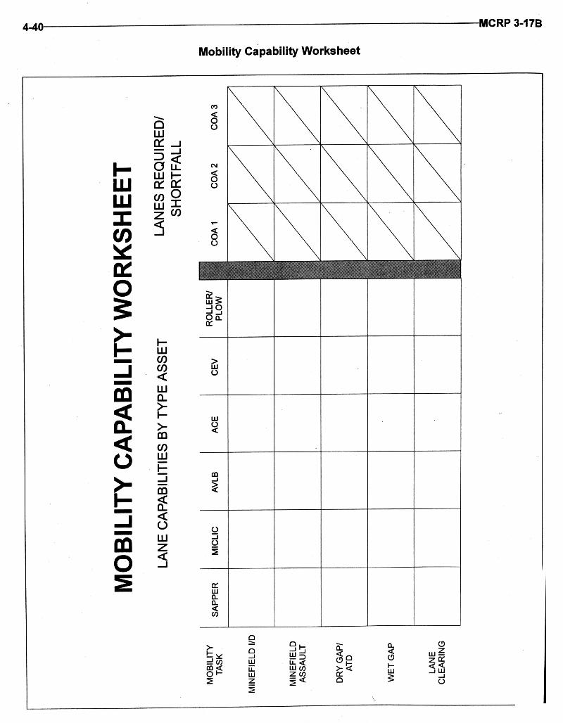


(This page intentionally left blank)
4-44 MCRP 3-17B

CLASSIFICATION BRIDGE ASSESSMENT
START PT: _____OF_____ END PT:
Engineer Forms and Reports 2-4
BRIDGE # BYPASS
LOCATION MIL GRID
MLCEXST/IMP
LGTH (M)/SPANS ()
BATTLEDAMAGE
SOLUTION TIMEREQUIRED
EXAMPLE: 1 IMPOSS AB 123456 50/70 45M/3 1 SPAN MGB 1.5 HOURS

BREACH COMPARISONIn Stride Deliberate Assault Covert
Enemy Situation Unclear or obstacle lightlydefended
Situation clear and/or obstacleheavily defended or complex
Enemy has protective obstacles;primary threat is small arms
Situation clear; tactical obstaclesbypassable; surprise critical tosuccess
Recon Quick; may be done during theattack
Extensive recon; detailed obsta-cle intel; verify enemy positionsand obstacles
Recon of protective obstaclesmay be limited to verifying pres-ence only
Extensive recon; detailed obsta-cle intel; obstacle compositioncritical
Planning Focus on allocating resources tosubordinates
Mass drives task org and syn-chronization drives planning
Task org focuses on assaultingplatoons
Mass drives task org; synch criti-cal; plan must achieve surprise
Synchronization SOSR synchronized at the subunit level
SOSR synchronized by thecommander
SOSR at two levels: Platoon: Point of penetra- tion TF: Isolate the objective area
SOSR synchronized by thecommander; obscure thrustealth secure and reduce/ sup-press only during assault
Reserve Plans Maintain mobility reserve; planfor transition to deliberatebreach
Small engineer reserve; be pre-pared to commit to breach orimprove lanes
No immediate reserve at as-saulting platoon level
Be prepared to deliberatebreach if detected; support forcefires, engineers resort to explo-sive reduction
Engineer TaskOrganization
Decentralized; redundant/ di-verse assets forward; mobilityreserve
Centralized; redundant/di- verseassets massed in breach forceechelon
Very decentralized; assets taskorganized down to maneuverplatoons/squads
Centralized; assets massed inbreach/security force
Rehearsals Focus on sub unit; emphasizecross training
Multi-echelon; train specifictasks and synchron- ization
Focus on platoon, squad, andfire team
Same as deliberate; must repli-cate limited visibility

Engineer Forms and Reports 2-6
VEHICLE CONCERTINAWIRE
M15MINE
M19MINE
M21MINE
M16MINE
MOPMSMINE
FLIPPERMINE
VOLCANOMINE
MICLICRELOAD
HMMWV, M9982,500 LB215 CU FT
2 51 34 27 55 15 11 1 *1
2 1/2 TON TRUCK5,000 LB443 CU FT
4 102 69 55 111 30 23 2 1
5 TON TRUCK10,000 LB488 CU FT
7 204 138 109 222 61 46 5 3
5 TON DUMP TRUCK10,000 LB135/291 CU FT ***
2/4 112/204 79/138 32/69 168/222 23/51 39/46 3/5 2/3
20 TON DUMP TRUCK40,000 LB754 CU FT
11 628 443 179 888 132 184 20 11
HEMITT TRUCK20,000 LB540 CU FT
8 408 277 128 444 94 92 10 7
12 TON S&P24,000 LB
13 489 333 208 533 148 110 12 9
40 TON LOWBOY80,000 LB1,760 CU FT
27 1,466 1,035 419 1,777 308 368 43 27
M54812,000 LB529 CU FT
8 244 166 125 266 74 55 6 4
#MINES/WT/LB
CUBECU FT
40/1,180
64 1/49
1.2 2/72
1.7 4/91
4.2 4/45
0.8 21/162
5.7 40/217
3.4 240/1,850
37.6 **2,656
64.8
CLASS IV AND V HAUL CAPABILITY
#for concertina= bundles; 1 bundle = 40 rolls *overloads vehicle **line charge and rocket ***without/with sideboards

ENGINEER ASSET SUMMARYUNIT CO/PLT MICLIC M9ACE D7DZR SEE CEV VOLCANO AVLB MGB RIBBON

Engineer Forms and Reports 2-8

START PT:_OF_END PT:


References and Related Publications
Joint Publications
Joint Pub 3-0 Doctrine for Joint Operations
Marine Corps Publications
Fleet Marine Force Manuals (FMFMs)
FMFM 3-1 Command and Staff ActionFMFM 13 MAGTF Engineer OperationsFMFM 13-7 MAGTF Breaching Operations
Marine Corps Reference Publications (MCRPs)
MCRP 4-25.5 Bulk Liquids Operations
Army Publications
U.S. Army Field Manuals (FMs)
FM 5-15 Field FortificationFM 5-34 Engineer Field DataFM 5-36 Route Reconnaissance and ClassificationFM 5-100 Engineer Combat OperationsFM 5-101 MobilityFM 5-102 CountermobilityFM 5-103 SurvivabilityFM 5-104 General EngineeringFM 5-250 Explosives and DemolitionsFM 6-20-40 Tactics, Techniques, and Procedures for Fire Support for Brigade Operations (Heavy)FM 6-20-50 Tactics, Techniques, and Procedures for Fire Support for Brigade Operations (Light)FM 10-52 Water Supply in Theaters of OperationFM 20-32 Mine/Countermine Operations
Engineer Forms and Reports B-1
APPENDIX B

Department of the Army Forms (DA Forms)
DA Form 1248 Road Reconnaissance ReportDA Form 1249 Bridge Reconnaissance ReportDA Form 1250 Tunnel Reconnaissance ReportDA Form 1251 Ford Reconnaissance ReportDA Form 1252 Ferry Reconnaissance ReportDA Form 1355 Minefield RecordDA Form 1711-R Engineer Reconnaissance ReportDA Form 2203-R Demolition Reconnaissance ReportDA Form 5032-R Field Artillery Delivered Minefield Planning Sheet
North Atlantic Treaty Organization (NATO) Publications
STANAG 2036 Land Minefield Laying, Marking, Recording and Reporting Procedures
The following list contains a brief description, the length, and current edition date of NATO StandardizationAgreements (STANAGs), Allied Technical Publications (ATPs), Allied Ordnance Publications (AOPs), andAllied Administrative Publications (AAPs) that are of interest to engineers but are not included because oftheir size or infrequent use.
NATO STANAGs
2010, Military Load Classification Markings, provides standardized system of marking the military loadclassification of bridges, rafts, and vehicles; 10 pages; July 1994.
2017, Orders to the Demolition Guard Commander and Demolition Firing Party Commander (Non Nuclear),provides standardized procedures to the Demolition Guard Commander and to the Demolition Firing PartyCommander in connection with the preparation, charging, and firing of non-nuclear demolitions in operationson land; 14 pages; July 1981.
2021, Military Computation of Bridge, Ferry, Raft, and Vehicle Classifications, provides instructions, charts,and graphs for calculating the load carrying capacity of bridges, ferries, and rafts and load effects of vehicles;40 pages; September 1990.
2096, Reporting Engineer Information in the Field, provides standardized minimum engineer reportingrequirements to be used by the NATO forces to ensure an adequate flow of engineer information duringoperations; 17 pages; January 1988.
2123, Obstacle Folder, provides standardized procedures to be used by the NATO nations in connection withthe preparation in peacetime of preplanned, preconstructed and/or field-type obstacle; 35 pages; November1984.
B-2 MCRP 3-17B

2136, Minimum Standards of Water Potability, provides criteria to standardize water potabiltiy betweenmilitary organizations. It also provides a list of water treatment equipment used by 14 NATO nations; 25pages; December 1985.
2321, The NATO Code of Colours for Identification of Ammunition (Except Ammunition of a Calibre Below20 mm, provides color coding criteria as indicated in the title, a listing of items to which the color coding doesnot apply, and color code identification charts; 10 pages; March 1993.
2394, Land Force Combat Engineer Doctrine, contains only the agreement to utilize the basic documentATP-52, Land Force Combat Engineer Doctrine; January 1993.
2395, Opposed Water Crossing Procedures, Standardizes procedures for conducting an opposed water in aforward combat area. It covers the following information: stages/phases, forces, critical functions, movementcontrol responsibilities, engineer tasks, responsibilities of the crossing unit, communications and combatservice support responsibilities, the crossing plan, terms and definitions, and charts showing the sequence ofcrossing events; 14 pages; September 1991.
2818, Characteristics of Demolition Accessories to Determine Their Operational Interchangeability,provides characteristics of demolitions materials used by various NATO members, as well as a generaldiscussion of demolition principles. It also provides instructions for conducting comparison tests to evaluatethe compatibility of foreign demolition materials; 188 pages; May 1979.
2885, Emergency Supply of Water in War, provides procedures to standardize the emergency supply of waterto NATO forces if the public water supply breaks down. It contains information pertaining to: definitions,requirements, quality and quantity, impurities, responsibilities, water sources, storage, distribution, andtreatment methods; 32 pages; November 1990.
2889, Marking of Hazardous Areas and Routes Through Them, provides instructions to standardizeprocedures to mark hazardous areas on land and those routes through or between them. It discussesrequirements, types of marking, definitions, and methods and procedures for marking various types of areas;15 pages; February 1990.
2933, Land Forces Explosives and Demolition Accessories Interchangeability Catalog in Wartime, containsonly the agreement to use the basic document AOP-19, Land Forces Explosives and Demolition AccessoriesInterchangeability Catalog in Wartime; September 1993.
2963, Coordination of Field Artillery Scatterable Mines, provides procedures to call for artillery-deliveredscatterable mine missions from the forces of other NATO nations by using standard calls, terms, procedures,and commands. It discusses employment, coordination, request procedures, reporting and planning data, andcharts; 24 pages; September 1992.
2989, Transfer of Barriers, outlines the procedures to be used by the NATO forces for the transfer of barriersbetween military forces of different nationalities. It contains the major considerations of barriers and detailedprocedures to successfully transfer the barrier; 40 pages; January 1985.
2990, Principles and Procedures for the Employment in Land Warfare of Scatterable Mines with a LimitedLaid Life, contains only the agreement to use basic document ATP-50, Principles and procedures for the
Engineer Forms and Reports B-3

Employment in Land Warfare of Scatterable Mines with a limited Laid Life, including change 2; September1995.
2991, NATO Combat Engineer Glossary, contains only the agreement to use the basic document AAP-19(B),NATO Combat Engineer Glossary; October 1993.
Allied Publications
Allied Technical Publications
ATP-50, Principles and Procedures for the Employment in Land Warfare of Scatterable Mines with aLimited Laid Life, provides standardized principles and procedures to be used by NATO forces whenemploying scatterable mines with a limited laid life in land warfare; 4 pages; September 1995.
ATP-52, Land Force Combat Engineer Doctrine, provides NATO combat engineer doctrine in the followingareas: the role of combat engineers, principles of employment, tasks in battle, defensive operations, delayingoperations, offensive operations, transitional phases, and special operations; 126 pages; February 1993.
Allied Ordnance Publication
AOP-19, Land Forces Explosives and Demolition Accessories Interchangeability Catalog in Wartime,provides a catalog of explosives and demolition items used by NATO forces, and shows which can beinterchanged and used by each nation during wartime. It is not intended for use in training or peacetimeoperations. It provides, where necessary, additional data, limitations, and/or clarifying information required foruse of such materials. The following information is provided for each item: NATO ammunitiondemand/reporting code, generic description, NATO stock number, national abbreviation and short code,quantity of issue, particular characteristics, and remarks; 55 pages; September 1993.
Allied Administrative Publication
AAP-19(B), NATO Combat Engineer Glossary, provides a glossary of terms and definitions of engineersignificance in both English and French languages; 48 pages; October 1993.
B-4 MCRP 3-17B

ANNEX C TO STANAG 2036 (Edition 4)SPECIAL INSTRUCTIONS FOR LAYING MINEFIELDS AND PREPARING
MINEFIELD RECORDS
1. When a minefield is changed, a new form will be submitted showing the entireminefield after the change. This does not apply if mines are subsequently dis-persed into an existing minefield or when lanes in an existing minefield areclosed, in which case the original record will be annotated (see paragraph 19.e.of the STANAG).
2. When “ measured-in-whole”, the minefield record must contain the followinginformation:
a. All landmarks and intermediate markers, if used. (A minimum of two land marks will be used.)
b. Bearings and distances:
(1) From landmark to its associated intermediate markers.
(2) From landmarks (or intermediate marker(s)) to nearest strip/row marker.
(3) From landmarks (or intermediate marker(s))to entrance of lanes (centerline).
(4) For each straight line section of lane(s) (center line).
(5) From end points of strip/row to end point of the following mine strip/row(in the direction of the enemy).
(6) For each straight line section of the mine strips/rows and of IOE baseline.
(7) From end points of forward strip/row to end points of IOE baseline.
(8) For each short mine strip/row associated with the IOE. The bearing shouldbe measured and recorded from the point of intersection of the short minestrip/row and the IOE baseline.
c. Locating number and types of stored mines or other means intended to beused for closing lanes.
d. Approximate location of perimeter fence, or line of warning signs when mine-fields are not fenced.
e. Number of mines in each strip or row (or short mine strip in IOE).
f. Total number of mines of each type.
g. Number of clusters in each short mine strip in IOE.
h. Location of mines with antilift devices or tripwire mines if applicable. (Clusternumbers to be entered in notes column.)
i. Period of effectiveness of mines with special fuzing systems.
Engineer Forms and Reports A-23
NATO Standardization Agreement (STANAG) 2036 Annex C

3. When “measured-in-part”, the minefield record should comprise as much of thefollowing information as possible:
a. Landmarks and intermediate markers, if required.
b. Corner points of mined terrain.
c. Bearings and distances from landmarks via intermediate markers to at leasttwo corner points.
d. Bearings and distances from corner point to corner point or end point of amine rov/strip to end point of an adjacent mine row/strip along the outline.
e. Number and types of mines.
f. Date/time of termination of minefield effectiveness when using mines equippedwith self-neutralizing fuzes.
g. Approximate location of fencing, or line of warning signs when minefields arenot fenced.
4. Nuisance minefields will normally be recorded as described in paragraph 3above. The extent of nuisance minefields around a prominent landmark will bedesignated by giving the radius in meters together with the grid reference of thelandmark. Elongated nuisance minefields will be designated by giving the gridreferences of the end points and their widths in meters. Information on numbersand types of mines, as well as on the time of effectiveness, is required.
5. The following symbols will be used when markers/points are shown on the mine-field diagram:
a. Landmark/Intermediate marker.
b. End point/corner point or Lane entrance/Lane exit.
c. Turning point.
A-24 MCRP 3-17B
NATO Standardization Agreement (STANAG) 2036 Annex C—Continued