mcrp 3-11 - globalsecurity.org · mcrp 3-11.4a helicopter insertion/extraction contents chapter...
TRANSCRIPT

MCRP 3-11.4A
Helicopter Insertion/Extraction
U.S. Marine Corps
PCN 000 000000 00
DEPARTMENT OF THE NAVY Headquarters United States Marine Corps
Washington, DC 20380-0001
Date
FOREWORD
Marine Corps Reference Publication (MCRP) 3-11.4A, Helicopter Insertion/Extraction, provides instruction for training Marines in the techniques, procedures, equipment and safety involved in conducting helicopter rope suspension operations. This publication establishes standards and serves as a guide for the realistic and safe training of Marines in helicopter rope suspension skills. It delineates responsibilities among aircraft maintenance activities, aircraft crew members and helicopter rope suspension training (HRST) personnel regarding the installation, manipulation, and maintenance of HRST equipment. HRST is the collective term for rappel, fast rope, Special Patrol Insertion/Extraction (SPIE), Jacob’s Ladder operations as these skills apply to insertion/extraction by helicopter and prerequisite training conducted from static towers. HRST gives units the ability to conduct helicopter insertions/extractions where helicopter landings are impractical. This reference publication applies to all commanders whose units conduct HRST operations and all Marines involved in those operations. This publication is not intended to teach the basics of rope training or the basics of rappelling as they apply to cliff assault. The intent is to outline techniques and procedures for rope suspension training and operations from helicopters. As with all Marine Corps doctrinal publications, this manual is authoritative in nature but requires judgment in application. This publication supersedes Fleet Marine Force Manual (FMFM) 7-40, Helicopter Insertion/Extraction, 11 May 1992. Reviewed and approved this date. BY DIRECTION OF THE COMMANDANT OF THE MARINE CORPS
E. J. HANLON Lieutenant General, U.S. Marine Corps
Commanding General Marine Corps Combat Development Command


MCRP 3-11.4A Helicopter Insertion/Extraction
CONTENTS
CHAPTER INTRODUCTION 1 HRST RESPONSIBILITIES AND SAFETY 2 HRST ROPES, EQUIPMENT, TERMINOLOGY, AND KNOTS 3 HRST TRAINING 4 RAPPELLING OPERATIONS 5 FAST ROPE OPERATIONS
6 SPECIAL PATROL INSERTION/EXTRACTION (SPIE) OPERATIONS
7 JACOB’S LADDER OPERATIONS
APPENDIX A HRST MISSION BRIEF TO HRST MEMBERS B HRST BRIEF TO AIRCREW C HRST COMMANDS D ROPE LOG E RAPPELL TOWER INSPECTION F GLOSSARY G REFERENCES AND RELATED PUBLICATION
1

MCRP 3-11.4A Helicopter Insertion/Extraction
CHAPTER l
HRST RESPONSIBILITIES AND SAFETY
PARAGRAPH PAGE
SECTION 1: RESPONSIBILITIES GENERAL 1200 5 UNIT COMMANDERS 1201 5 HRST MASTER 1202 5 HRST SAFETY INSERT OFFICER (SIO) 1203 7 HELICOPTER AIRCRAFT COMMANDER (HAC) 1204 8 HELICOPTER CREW CHIEF 1205 9 INDIVIDUAL ROPERS 1206 10 SECTION 2: SAFETY GENERAL 1300 12 CREW COORDINATION 1301 12 EMERGENCY PROCEDURES 1302 13 OPERATIONAL SAFETY 1303 16 FIGURES PAGE 1-1 ROTOR DOWNWASH 17 1-2 GUNNERS BELT 20 1-3 POSITION OF WEAPON 21 1-4 POSITION OF EQUIPMENT 21
2

MCRP 3-11.4A Helicopter Insertion/Extraction
1
CHAPTER l
HRST RESPONSIBILITIES AND SAFETY
PARAGRAPH PAGE SECTION 1: RESPONSIBILITIES GENERAL 1200 2 UNIT COMMANDERS 1201 2 HRST MASTER 1202 2 HRST SAFETY INSERT OFFICER (SIO) 1203 4 HELICOPTER AIRCRAFT COMMANDER (HAC) 1204 5 HELICOPTER CREW CHIEF 1205 6 SECTION 2: SAFETY GENERAL 1300 8 CREW COORDINATION 1301 8 EMERGENCY PROCEDURES 1302 9 OPERATIONAL SAFETY 1303 11 FIGURES PAGE 1-1 ROTOR DOWNWASH 13 1-2 GUNNERS BELT 16 1-3 POSITION OF WEAPON 17 1-4 POSITION OF EQUIPMENT 17

MCRP 3-11.4A Helicopter Insertion/Extraction
2
CHAPTER 1
HRST RESPONSIBILITIES AND SAFETY
SECTION 1: RESPONSIBILITIES
1200. GENERAL. The responsibilities associated with safe HRST evolutions are numerous. This section tasks and defines specific responsibilities associated with HRST operations. 1201. UNIT COMMANDERS. Each Commander's primary responsibility is to ensure that all HRST within their respective unit is accomplished in a safe manner and in accordance with this publication and Marine Corps Order 3500.21. Additional responsibilities include, but are not limited to the following:
a. Ensure that HRST within the unit is conducted and supervised by a certified and current HRST Master and Safety Insert Officer (SIO).
b. Ensure that all HRST certifications and currency dates are properly annotated in each Marine's SRB/OQR as appropriate, and Training Record.
c. Ensure that all personnel conducting rope suspension training from a helicopter have successfully completed static tower training within the previous 60 days. d. Ensure that all HRST equipment assigned on the unit's table of equipment is properly maintained, inspected and stowed after use, in accordance with chapter 2. e. Submit any recommended additions or changes to this manual. 1202. HRST MASTER. The HRST Master's primary responsibility is the conduct of the HRST. The HRST Master must be knowledgeable of the contents of this manual in its entirety and be knowledgeable of all current HRST policies and directives. If the situation warrants (ie. the HRST Master is an integral member of a Recon unit), the HRST Master may participate as a roper. In this situation the HRST Master will be the last man out. Specific responsibilities of the HRST Master include: a. The safety of all insertion personnel from the planning stage until they are safely inserted into the drop zone. For SPIE training, the HRST Master is responsible for the safety of SPIE personnel from the moment they "hook up" until the moment they are clear from the SPIE rope. b. Ensure that the HRST equipment in use is serviceable in accordance with Chapter 3. c. Descent Authority. It is the sole responsibility of the HRST Master to order the roper's descent/extraction. The HAC may abort or cancel a descent when conditions are considered unsafe.

MCRP 3-11.4A Helicopter Insertion/Extraction
3
d. Extraction Authority. Extraction of personnel during SPIE operations is a shared responsibility. The HRST Master shall inform the HAC when the ropers are connected and ready to lift. The crew Chief shall check for obstacles and clear the HAC for lift and transition to forward flight. e. Relief. The HRST Master, if determined to be incompetent, may be relieved by another HRST Master or SIO. The HRST Master relieving him will immediately assume his duties until the HRST is complete. If no HRST Master is present during relief, further HRST shall be canceled. f. Preflight. Preflight responsibilities of the HRST Master include: (1) Conduct a detailed briefing of all personnel to be inserted/extracted in accordance with Appendix A (HRST Mission Brief to HRST Members). (2) Conduct a joint face-to-face brief with the aircrew in accordance with appendix B (HRST Brief to Aircrew). During initial training it is desirable to have the aircraft shutdown during this brief. Requiring the aircraft to shutdown for this portion of the training should be specifically stated when the request for helicopter support is submitted, otherwise, shutting the aircraft down will be left to the discretion of the aircraft commander. Ensure that HRST Commands (appendix c) and emergency procedures are clearly understood by all participants. (3) Ensure proper attachment, installation, padding, and inspection of all ropes and devices associated with the HRST are in accordance with chapters 3 through 6. The preflight inspection will include condition of the aircraft's floor surface. Any fluid spills on the aircraft's floor surface will be brought to the aircrew's attention for correction. (4) Ensure that a rope cutting device (i.e. ax, hatchet, knife, machete) is available for use during rope entanglement or other similar emergency. g. In flight. In flight responsibilities of the HRST Master include: (1) Maintain a line of communication with the aircrew at all times either by ICS (inter communication system) or by hand and arm signals in the event of ICS failure. (2) Respond (challenge and reply) to all voice commands from the HAC. (3) Fully comply with all aircrewmen's instructions. (4) Deploy the rope or direct for it to be deployed only after the aircraft has been stabilized in a hover and the HAC commands, "DEPLOY THE ROPE." (5) Ensure the orderly movement of ropers from their "strapped in" position to the rope station.

MCRP 3-11.4A Helicopter Insertion/Extraction
4
(6) Make a final inspection of ropers as they approach the rope station checking for loose equipment or missing safety equipment.
(7) Monitor the ropers' descent until they are safely clear of the rope. Advise the aircrew of any problems encountered.
(8) Monitor the condition and security of the rope and anchor points, being watchful for signs of wear and slippage. (9) Ensure that ropes maintain proper contact with the ground. Advise aircrew when proper contact is not being maintained. (10) Retrieve or release the rope once all ropers are safely on the deck and clear of the deplaning station. (11) Cut the rope only in case of an emergency and only on the "CUT ROPE" command from the HAC. h. Post flight. Post flight responsibilities of the HRST Master include: (1) De-rig all HRST equipment and padding from the aircraft. (2) Conduct a post flight debrief with all HRST participants. (3) Inspect all HRST equipment for wear and properly stow all equipment in accordance with chapter 2. Make appropriate log book entries concerning rope utilization. 1203. HRST SAFETY INSERT OFFICER (SIO). The SIO's primary responsibility is to oversee and supervise all phases of the HRST training. The SIO will be a current HRST Master. The SIO has overall responsibility of the operation. He will be guided in his duties by this manual and all current HRST policies and directives. He will be present for every phase of training. Whenever possible, the SIO will be located in the drop zone and will monitor the actions inside the aircraft by means of radio communication. When it is not feasible for the SIO to be in the drop zone he will position himself in the aircraft. If the situation warrants it, the SIO may participate as a roper. In this situation the SOI will be the last man out. When the HRST Master is also a roper, the HRST Master will be the last man out and the SIO will be the second to the last man out. The SIO will ensure that all HRST is conducted in a safe manner. The SIO's supervisory responsibilities include, but are not limited to: a. Ensure that all HRST Master's briefs are conducted. b. Ensure that the HAC briefs the conduct of the flight and emergency procedures. c. Complete pre-operation and post-operation inspections of aircraft rigging and equipment.
MCRP 3-11.4A Helicopter Insertion/Extraction
5
d. Ensure that the aircrew has on hand all required aviation equipment and that it is properly used by HRST personnel (i.e. ICS headsets and gunners belts for the HRST Master).
e. Position himself in the aircraft or on the deck in order to monitor the conduct of the HRST and ensure that a safe environment is being maintained. f. Monitor the aircraft radio frequency being utilized and be prepared to issue warnings and instructions. g. "ABORT" the HRST training at anytime the training is not proceeding as briefed, the aircrew is having difficulty in maintaining a steady hover, or in the event of any other unforeseen circumstance that may impact on a safe evolution. 1204. HELICOPTER AIRCRAFT COMMANDER (HAC). The HAC's primary responsibility is the safe conduct of the flight. a. Preflight. Preflight responsibilities of the HAC include: (1) Detailed preflight planning to ensure that the ratio of power available to power required, the weather conditions, the ambient light conditions, and the drop zone conditions are conducive to safe HRST operations. (2) Ensure that the aircraft surfaces to be utilized for HRST are clean, dry, and free of oily substances. (3) Inspect HRST rigging to ensure that it is adequately padded and that it will not damage the aircraft or create a hazard. (4) Conduct a thorough joint face-to-face brief with the HRST Master and SIO. The brief shall include the following:
(a) Conduct of the flight.
(b) Hover altitude.
(c) Number of ropers.
(d) Communication procedures between aircrew, HRST Master, and SIO (including procedures should electronic communications fail).
(e) Responsibilities of the HAC, HRST Master, and crew chief.
(f) Responsibilities of all HRST personnel in the event of an aircraft emergency. b. In flight. In flight responsibilities of the HAC include:

MCRP 3-11.4A Helicopter Insertion/Extraction
6
(1) Conduct the flight as briefed.
(2) Authorize "DEPLOY THE ROPE" once established in a stable hover.
(3) "ABORT" the mission if aircraft or environmental factors prohibit a stable hover.
(4) Ensure that a line of communications is maintained between aircrew, HRST Master and SIO.
(5) Respond (challenge and reply) to all commands from the crew chief and HRST Master.
(6) Authorize unbuckling of seatbelts and movement to rope stations.
(7) Authorize "CUT ROPE" in the event of an aircraft emergency and no other options are available. The HAC has sole responsibility to order that a rope be cut. Cutting a rope is a "last ditch" effort to save lives. (8) Forward Flight. With the assistance of the crew chief and HRST Master, the HAC is responsible for transition of the aircraft to forward flight. c. Post flight. Post flight responsibilities of the HAC include participating in a thorough debrief of all HRST members. 1205. HELICOPTER CREW CHIEF. The crew chief's primary responsibly during HRST is to assist the pilot with terrain/obstacle clearance and with maintaining the aircraft over the target area by passing voice instructions to the pilot. During HRST operations the crew chief assumes certain responsibilities and duties in addition to his normal aircrew member duties. a. Preflight. Preflight responsibilities of the crew chief include:
(1) Ensure sufficient operable ICS headset devices and gunner's belts are available for the HRST Master and his assistants, as required.
(2) Ensure the aircraft surfaces to be utilized for HRST are clean, dry, and free of oily substances.
(3) Ensure loose equipment and rope ends do not create hazards or preclude movement inside the aircraft.
(4) Participate in the preflight HRST brief to aircrew and when possible, attend the HRST mission brief to HRST members. b. In flight. In flight responsibilities of the crew chief include:

MCRP 3-11.4A Helicopter Insertion/Extraction
7
(1) Assist the pilot in maintaining a steady hover by passing voice instructions concerning the helicopter's position over the target area. (2) Assist the HRST Master in passing voice instructions to the HAC in the event of ICS failure. NOTE: In the event of ICS failure HRST operations shall be terminated. HRST may continue only when operable ICS has been restored. (3) Ensure that all HRST Masters wear gunner's belts when operating in the vicinity of a rope station.
(4) Ensure all ropers remain strapped in until instructed to "UNBUCKLE" by the HRST Master. (5) Monitor the condition and security of ropes and anchor points, being watchful for signs of wear and slippage. (6) Ensure all ropes are clear of ropers and that all ropes are either retrieved, released, or clear of ground obstacles before passing clearance for forward flight. (7) Advise the pilot that the aircraft is clear for forward flight by passing "CLEAR FOR FORWARD FLIGHT" to the HAC. c. Post flight. Post flight responsibilities of the crew chief include participating in the post flight debrief of all HRST members and ensuring that HRST equipment has been properly removed from the aircraft.

MCRP 3-11.4A Helicopter Insertion/Extraction
8
CHAPTER 1
HRST RESPONSIBILITIES AND SAFETY
SECTION 2: SAFETY 1300. GENERAL. The number one priority is combat readiness; the development of HRST skills builds upon combat readiness. HRST is a high-risk evolution, one in which safety is of paramount concern. HRST can be conducted safely as long as the contents of this publication are adhered to and current directives are followed. Noncompliance with this reference, current directives and/or unauthorized modifications to HRST equipment or installation of equipment may result in injury to personnel and/or damage to aircraft and equipment. Safety awareness cannot be over emphasized during HRST. It is each individual's responsibility to ensure that the contents of this publication are understood and complied with so that a safe training environment is maintained. Every Marine involved in HRST has the authority to question an unsafe situation and to have any unsafe situation corrected prior to the continuation of training. In all cases, HRST will follow a "building block approach" to training. HRST will only be conducted by personnel qualified in accordance with the current version of Marine Corps order 3500.21. l30l. CREW COORDINATION. Maintaining good crew coordination is a very critical factor in conducting a safe HRST evolution. The following two areas are mandatory crew coordination requirements for HRST. a. Briefings. Face-to-face briefings will be conducted by all HRST participants. The HRST Master will give a detailed HRST Brief to HRST Members (appendix A). This brief will be conducted with aircrew present whenever possible. The HRST Brief to Aircrew (Appendix B) shall be conducted jointly between the HRST Master, the SIO, and the aircrew. The HAC will brief emergency procedures to all HRST participants. During the conduct of the briefings the HRST Master and HAC will ensure that the following areas are clearly understood by all: (1) Conduct of the flight. (2) Responsibilities of each HRST member. (3) Communications and commands between SIO, HRST Master, HAC, and crew chief. (4) Emergency procedures. b. Communications and HRST Commands (1) ICS. Operable ICS is mandatory for HRST. ICS headsets must be provided for all HRST Masters. Loud and clear inter-communications between the pilots, crew chief, and the HRST Master must be maintained at all times. In the event of ICS failure hand and arm signals will be utilized to cease HRST until the problem is corrected.

MCRP 3-11.4A Helicopter Insertion/Extraction
9
(2) Challenge and Reply. The method of "challenge and reply" is mandatory for all HRST commands between aircrew members and the HRST Master. Utilizing challenge and reply will assist in providing clarity to intercommunications and will provide assurance to all HRST members that commands have been passed and received.
(3) Operable radio communications must be maintained between the aircraft and the SIO located in the drop zone. During tactical operations the SIO may be aboard the aircraft. ICS will be provided for the SIO.
(4) Ropers must rely on hand and arm signals and verbal commands from the HRST Master for communications inside the helicopter prior to insertion. (5) A clear understanding of all HRST commands and hand and arm signals is mandatory by all HRST members and air crewmen (see appendix C). 1302. EMERGENCY PROCEDURES. The following emergencies could reasonably be encountered during HRST. Aircraft emergencies, adverse weather, or other unusual conditions may require modifications to these procedures. The nature and severity of the emergency will dictate the degree of compliance necessary; therefore, personnel must use sound judgment to determine the correct action to be taken. a. Aircraft Emergency. If the helicopter experiences engine failure or any other aircraft emergency during HRST, the ropers will descend as rapidly as possible and move from beneath the helicopter to the six o'clock position. The HAC shall attempt to land the helicopter by moving forward to the twelve o'clock position. In the event of an aircraft emergency the HRST Master shall: (1) "AB0RT" (cease rope operations) on the command of the HAC. (2) Ensure ropers already descending the rope are clear of the rope and possible helicopter impact area. (3) Direct ropers still inside the aircraft to stay clear of openings, retake seats, and "STRAP IN". All personnel shall then follow the directions of the crew chief. b. Unsafe Drift or Premature Lift Off. If the helicopter gains altitude so that the rope no longer touches the ground or if the helicopter drifts off target: (1) The HRST Master shall pre-brief Marines already descending to "LOCK IN" or "BRAKE" and await helicopter descent. For fast rope operations, this is best achieved by attempting to wrap one leg around the fast rope and placing the other foot on top of the rope as it passes over the top of the first foot. For rappelling operations, simply maintain a brake. (2) The HRST Master shall stop ropers from starting a descent (ABORT).
MCRP 3-11.4A Helicopter Insertion/Extraction
10
(3) Once back on target and/or altitude and on approval from the HAC, the HRST Master may continue safe operations. c. Lost Communications/ICS Failure. Communication between the HRST master, aircraft commander, crew chief and SIO is mandatory. In the event of ICS failure the following hand and arm signals apply (Appendix C): (1) The signal to "ABORT" (cease rope operations) is a slashing motion of the right hand across the throat. (2) The signal to reposition the aircraft is an open palm moved in the direction required. (3) The signal to "HOLD" is a clenched fist. This signal means stop aircraft's movement or to lock in or brake (if directed at a roper). (4) The signal for retaking seats is to point a finger toward the seats. (5) The signal to "STRAP IN" is to move both clinched fists together at the waist. NOTE: Hand and arm signals will be utilized to complete the descent of the roper on the rope at the time of the ICS failure. d. Hung Roper. A roper who has exited the aircraft and is unable to complete his descent to the ground poses a potentially dangerous situation. The HRST Master's first consideration will always be the safety of the roper. A roper can become "hung" for a variety of reasons (i.e. fouled rope, loose clothing, straps, equipment, misplaced hand). In the event of a hung roper the following steps will be taken: (1) The HRST Master will immediately notify the HAC. (2) If possible, the pilot will lower the roper to the ground. (3) If the pilot is unable to land and must search for a landing site, the HRST Master will tie a loop figure 8 on the safety line, he will then attach a steel locking carabiner. This carabiner will then be connected and lowered on the rappel ropes. The hung roper will disconnect the safety carabiner from the rappel ropes and reconnect the safety carabiner and safety line to his seat carabiner. The safety line will be secured to the inside of the aircraft at an anchor point opposite of the fouled rope's anchor points.(4) The HAC will be notified and the crew chief will assist.
(5) The helicopter, if possible will descend until the hung roper's feet are on the deck. If the hung roper is within ten feet of the aircraft the rope will be cut. However, if the roper is hung in excess of ten feet from the aircraft he will be assisted by the belay man and SIO to clear the rope.
(6) If the helicopter cannot descend a safety line will be rigged to establish a belay point.

MCRP 3-11.4A Helicopter Insertion/Extraction
11
This will be accomplished by rigging the safety line to the anchors opposite of the rappel station.
(7) To rig the belay the HRST Master will tie a loop fig 8 on one end of the safety line and attach a steel locking carabiner. The safety line and steel locking carabiner will be attached to the rappel ropes and lowered to the hung roper. The hung roper will disconnect the safety line/carabiner from the rappel ropes and reattach them to his rappel seat . The HRST Master will secure the other end of the safety line with a suitable anchor knot to the anchor points opposite of the rappel system leaving the last anchor point or the anchor closest to the ramp vacant. On this anchor point the Master will attach a steel locking carabiner, to this carabiner the safety line will be attached via a mutter hitch. The slack will be removed from the safety line and the brake applied. At this point the rappeler will be instructed to free himself from the rappel system.
(8) By releasing tension on the safety rope (belay), lower hung roper and rope to the ground. e. Fouled Rope. A rope may become fouled or entangled on ground obstacles during the course of HRST operations. In the event of a fouled rope execute the following procedures:
(1) Ensure all ropers are clear. (2) If possible, descend or reposition aircraft over target to decrease tension on the rope. (3) Release the rope. (4) If sufficient tension cannot be released in order to release the rope, the HAC may command, "CUT ROPE." The HRST Master must have a rope cutting device available during HRST operation. f. Accident Procedures. In the event of an accident the first priority is to injured personnel. (1) Medical personnel/equipment are required to be present for all HRST training evolutions. A backboard is mandatory medical equipment. (2) Transport injured personnel to the closest military hospital or civilian facility, if training away from a military installation. (3) If possible, radio ahead the nature of the Marine's injury and the ETA (estimated time of arrival) of the aircraft/emergency vehicle. (4) Notify all proper authorities and file appropriate reports and statements of witnesses. 1303. OPERATIONAL SAFETY. The following factors effect safe HRST operations. These measures are minimum safety requirements that must be complied with.
MCRP 3-11.4A Helicopter Insertion/Extraction
12
a. Environmental Factors. Environmental factors may affect the pilot's ability to safely position and maintain the position of the helicopter over the target area. Also, the effects of altitude, temperature, and humidity greatly effect aircraft performance. (1) Minimum Obstacle Clearance. A minimum of ten feet vertical clearance and fifteen feet horizontal clearance is mandatory while conducting a hover for HRST operations. (2) All care must be taken to select a drop/pickup zone that is relatively free of dust, snow, or other objects that could obscure the pilot's vision.
(3) If the pilot is unable to detect a visible horizon or acquire visual reference points due to weather conditions (i.e. fog, haze) or other factors, then HRST operations must be aborted.
(4) Pilots must complete a proper weight and balance calculation to determine if the environmental factors will permit safe HRST operations. b. Night Factors. Night operations further affect the pilot’s ability to maintain a steady position over the target area. It also challenges the HRST Master's ability to maintain control of ropers during the conduct of HRST.
(1) Night HRST operations may be conducted with or without Night Vision Goggles (NVG) as long as the pilot is able to maintain a steady position over the target area and all other qualifications and conditions for NVG operations are met.
(2) Chem Lights. The use of multicolored "chem lights" is mandatory for night fast rope to assist the HRST Master in determining rope and roper positions. By attaching one chem light to the running end of the fast rope and one chem light 10-20 feet from the running end of the rope, the HRST Master can determine when the rope is in contact with the ground and how much of the rope is on the ground. One chem light placed at the standing end (anchor point) of the rope in use gives ropers a reference for grabbing the rope. A small "fire fly" chem light on each roper gives the HRST Master a reference of each roper's position. Chem lights can also assist with hand and arm signals during night HRST operations. Chem lights are generally compatible with NVG operations where flashlights without the proper blue light lens are not. c. Aircraft Factors. Numerous phenomenon associated with helicopter operations will affect safe HRST.
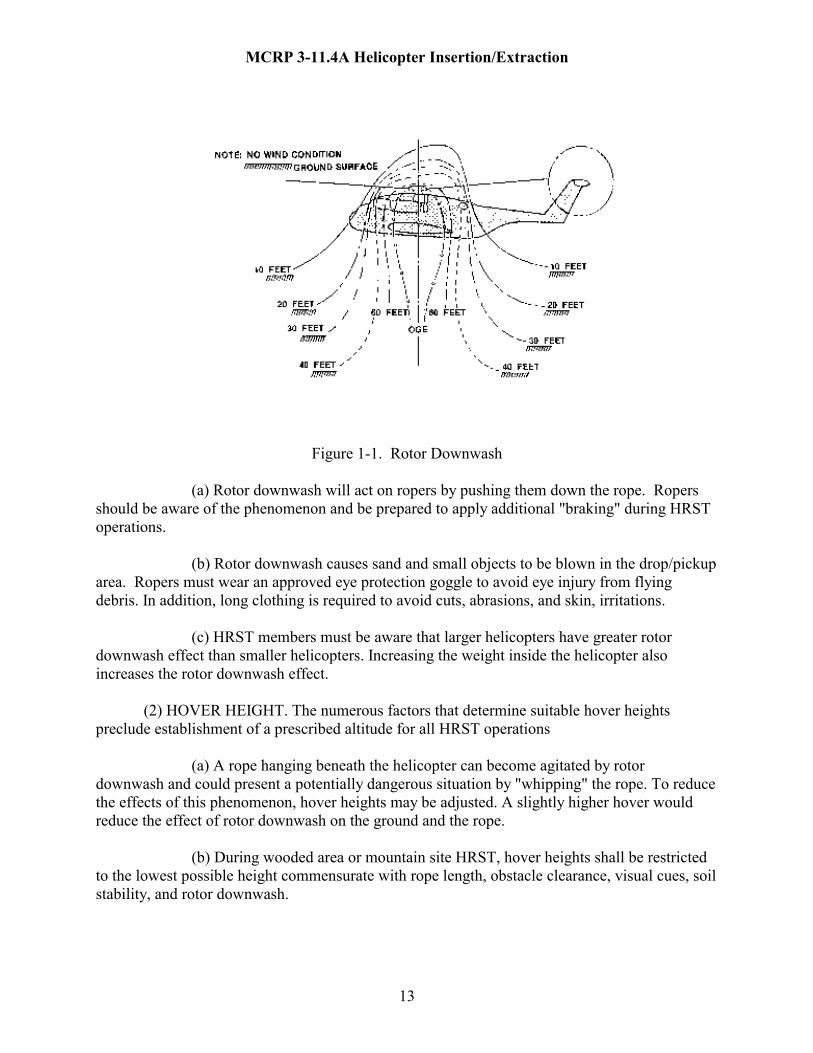
(1) Rotor Downwash. Due to rotor downwash effects (Figure 1-1), HRST members must be cautious of several factors:
MCRP 3-11.4A Helicopter Insertion/Extraction
13
Figure 1-1. Rotor Downwash (a) Rotor downwash will act on ropers by pushing them down the rope. Ropers
should be aware of the phenomenon and be prepared to apply additional "braking" during HRST operations.
(b) Rotor downwash causes sand and small objects to be blown in the drop/pickup area. Ropers must wear an approved eye protection goggle to avoid eye injury from flying debris. In addition, long clothing is required to avoid cuts, abrasions, and skin, irritations.
(c) HRST members must be aware that larger helicopters have greater rotor downwash effect than smaller helicopters. Increasing the weight inside the helicopter also increases the rotor downwash effect.
(2) HOVER HEIGHT. The numerous factors that determine suitable hover heights preclude establishment of a prescribed altitude for all HRST operations
(a) A rope hanging beneath the helicopter can become agitated by rotor downwash and could present a potentially dangerous situation by "whipping" the rope. To reduce the effects of this phenomenon, hover heights may be adjusted. A slightly higher hover would reduce the effect of rotor downwash on the ground and the rope. (b) During wooded area or mountain site HRST, hover heights shall be restricted to the lowest possible height commensurate with rope length, obstacle clearance, visual cues, soil stability, and rotor downwash.
MCRP 3-11.4A Helicopter Insertion/Extraction
14
(3) Static Discharge. Static electricity is generated by a helicopter and is discharged from the aircraft by contact with the ground.
(a) Dry Conditions: Ropes are nonconductive and do not allow static electricity to be discharged through them. Ropers may experience a small harmless shock upon reaching the ground due to the body's capacitance, but the shock will probably be masked by other sensations associated with HRST.
(b) Wet Conditions: Ropes may become conductive if wet or contaminated with fluids. Conductivity lessens, however, as the length of the rope increases.
(c) Personnel will not be in contact with the rope as it touches the ground due to the remote possibility that the rope may conduct static electricity.
(d) HRST operations will not commence until the rope has made contact with the ground. d. Inner Aircraft Safety. The following recommendations and warnings enhance the safety inside the aircraft: (1) Hand Holds. Whenever possible, hand holds should be improvised to assist roper's movement from their strapped in positions to the rope stations, especially near a rope station. Cargo straps, ropes, or webbing can be secured overhead to provide a secure hand hold during movement. (2) Loose Combat Gear. Combat Gear left adrift, loose padding, and rope ends left un-policed inside the aircraft pose a potential tripping hazard to ropers as they move to rope stations. This is especially true during night operations. (3) "Hell Hole" Operations. During HRST operations utilizing the aircraft's hell hole, all personnel inside the aircraft must be particularly cautious to avoid accidentally falling through the hell hole. Whenever possible the hatch to the hell hole should remain closed until required for use. (4) Rope Stations. A qualified HRST Master shall be located at each rope station to ensure positive control. e. Equipment and Clothing Safety. All HRST operations will include the following safety equipment and clothing measures: (1) Padding. The entire edge of the ramp, door, or hatch across which a rope is expected to lie shall be padded with appropriate material (i.e. two thickness of one half inch hair felt pads, carpet, or other suitable material) ensuring that all sharp edges are padded and not merely taped over.

MCRP 3-11.4A Helicopter Insertion/Extraction
15
(a) Any corners or edges of the ramp, door, or hatch against which ropes might rub shall be similarly padded.
(b) Where possible, the padding must extend from the edges of the opening at least 18 inches toward the anchor point and 18 inches back and around the bottom edges and away from the edge on the outside of the aircraft.
(c) All padding shall be adequately secured in place so that it will not be inadvertently misplaced. All surfaces must be clean and free of oily fluids so that tape will adhere.
(d) "Grunt Chute". To avoid snagging when going through the hell hole, the inside of the hell hole may be lined to form a "grunt chute." This can be accomplished by padding.
(2) Safety Ropes/Anchor Points. Whenever possible, HRST operations shall be conducted with a redundancy of safety "back-up" ropes and rope anchor points.
(a) Rope suspension configurations shall be utilized that ensure that the weight applied is evenly spread-loaded to numerous anchor points. If the load factor of an anchor point is known and exceeds the minimum required load factor, then an "in line" configuration may be utilized to attach ropes to anchor points. (b) All rope suspension configurations will incorporate secondary and, where possible, tertiary anchor points. (c) Attaching any object to the running end of the rappel rope is prohibited. The only exception to this safety precaution is attaching a chem light to the end of the rappel rope during night operations in accordance with paragraph 4101.e. (3) Safety clothing. The following safety clothing is a minimum requirement to ensure personnel safety: (a) Uniform. The utility uniform should be worn with sleeves rolled down and buttoned. The blouse should be tucked into the trousers in order to reduce the possibility of snagging on protruding objects or of becoming fouled in ropes. The belt buckle should be moved to the left hand side. The wearing of loose bulky clothing should be avoided.
(b) Cranial Protection. Units will wear appropriate head protection according to mission requirements.
(c) Eye Protection. Units will wear appropriate eye protection according to mission requirements.
(d) Gloves. A heavy leather outer glove and a lighter material liner are mandatory for rappelling and fast rope operations.

MCRP 3-11.4A Helicopter Insertion/Extraction
16
(e) Ear Protection. Earplugs or other sound suppressive devices are mandatory
for helicopter operations.
(f) Sling Rope. A 12-15 feet piece of rappelling rope utilized to fashion a Military Rappel seat or safety harness.
(g) Flotation and emergency escape breathing device. An LPP or other approved Personnel Flotation Device (PFD) and an approved emergency escape breathing device is mandatory for fast roping and rappelling operations over water.
(h) Gunner's Belt. A gunner's belt is mandatory for the HRST Master or any HRST member who is positioned at an aircraft opening or rope station. (Figure 1-2)
Figure 1-2. Gunner’s Belt
(i) Operational Equipment. Operational equipment, when required, will be worn
in a manner to reduce the possibility of snagging.
1 Weapons should be worn diagonally across the back with the muzzle pointed down and away from the brake hand while rappelling (Figure 1-3). The rifle will be attached by 550 cord, rifle sling, or similar material.

MCRP 3-11.4A Helicopter Insertion/Extraction
17
Figure 1-3. Position of Weapon 2 When combat gear is worn, the web belt may be buckled behind the roper to keep equipment clear during a fast rope descent. If buckled in the front, equipment should be removed from the right hand side during rappelling operations. 3 When the ALICE pack is worn, combat gear may be placed inside of the pack. If combat gear is to be worn, equipment should be removed from the right hand side of the web belt (Figure 1-4). Figure 1-4. Position of Equipment

CHAPTER 2
HRST ROPES, EQUIPMENT, TERMINOLOGY, AND KNOTS PARAGRAPH PAGE SECTION 1: ROPE AND EQUIPMENT NOMENCLATURE GENERAL 2100 20 GROUND EQUIPMENT 2101 20 AVIATION EQUIPMENT 2102 30 SECTION 2: ROPE AND EQUIPMENT MANAGEMENT GENERAL 2200 33 GROUND EQUIPMENT 2201 33 AVIATION EQUIPMENT 2202 37 SECTION 3: HRST TERMINOLOGY AND KNOTS GENERAL 2300 39 HSRT TERMINOLOGY 2301 39 HRST KNOTS 2302 40 FIGURES 2-1 STATIC KERNMANTLE ROPE 20 2-2 PLIMOORE FAST ROPE 21 2-3 SPIE ROPE 22 2-4 SPIE HARNESS 23 2-5 LIGHTWEIGHT SPIE HARNESS 23
18

2-6 CARGO SUSPENSION SLING 24 2-7 RAPPEL ROPE ATTACHMENT CABLE 25 2-8 STUBAI 85 CARABINER 25 2-9 RESCUE 8 DESCENDER 26 2-10 FAST ROPE INTERFACE KIT 27 2-11 FAST ROPE INTERFACE KIT INSTALLED 28 2-12 SCHLOMER FRAME 30 2-13 FAST ROPE GANTRY 31 2-14 FAST ROPE ANCHOR BAR 32 2-15 A-FRAME FAST ROPE ATTACHMENT BAR ASSEMBLY 32 2-16 END OF ROPE WHIPPING 33 2-17 MOUNTAIN COIL 35 2-18 BUTTERFLY COIL 35 2-19 FAST ROPE CRIMP 36 2-20 SQUARE KNOT 41 2-21 BOWLINE KNOT 42 2-22 CLOVE HITCH 42 2-23 FIGURE "8" LOOP 43 2-24 OVERHAND KNOT 43 2-25 MULTI-DIRECTIONAL PRUSIK 44 2-26 DIRECTIONAL FIGURE "8" LOOP 44 2-27 MILITARY RAPPEL SEAT 45 2-28 AROUND THE BODY BOWLINE 45
19

MCRP 3-11.4A Helicopter Insertion/Extraction
CHAPTER 2
HRST ROPES, EQUIPMENT, TERMINOLOGY, AND KNOTS
SECTION 1: ROPE AND EQUIPMENT NOMENCLATURE 2100. GENERAL. The equipment contained in this section is approved for HRST operations. Deviations or substitutions to HRST equipment must be approved through the appropriate chain of command to the Commandant of the Marine Corps, Deputy Commandant, Plans, Policies and Operations (CMC, DC PP&O). 2101. GROUND EQUIPMENT. The equipment listed below is provided and maintained by the ground unit conducting the HRST: a. STATIC KERNMANTLE ROPE (Figure 2-1).
(1) National stock number (NSN): General service (GS) Contract #GS07F14181
(2) Characteristics: A high strength inner core covered by an outer woven sheath.
(a) Diameter: 11mm (7/16")
(b) Tensile strength: 7500 pounds, 6500 for Blue Water Assault Line
(c) Length: commonly 150 feet, available up to 600' spool.
(d) Color: Olive drab/Black
(e) Static Kernmantle rope is graded as SERVICEABLE or UNSERVICEABLE.
(f) A rope log must be maintained with every use of all ropes recorded in it (see appendix D).
(g) All ropes have a shelf life of five years and a service life of two years.
Figure 2-1. Static Kernmantle Rope
20

MCRP 3-11.4A Helicopter Insertion/Extraction
b. PLIMOORE FAST ROPE (Figure 2-2).
(1) NSN: 50 ft. None assigned 60 ft. 4020-01-338-3307 90 ft. 4020-01-338-3308 120 ft. 4020-01-338-3309
(2) Characteristics: Military green, multiple strands, right hand lay, natural. Made of multifilament polyester over multifilament polypropylene. Rope has an end cap assembly with a 3 inch steel ring for aircraft anchoring. A 3/16 inch steel cable is attached to provide a safety "back-up" anchor point to the end cap assembly.
(a) Diameter: 1 3/4 inch
(b) Lengths: 50, 60, 90, 120 feet
(c) Tensile strengths: Fast rope 35,000 lbs Steel safety cable: 3,700 lbs
End cap assembly 9,000 lbs
(d) Inspection: If one strand is broken on the safety cable the fast rope is unserviceable. Check the end cap assembly for missing screws, and cracks.
(e) All fast ropes manufactured by the Columbia Rope Company after 1996 will have the Roman numeral “I” stamped on the head. Ropes manufactured by Columbia Rope Company after 1996 that do not have Roman numeral ‘I” must be recrimped and stamped prior to use.
Note: Columbia Rope Company also manufactures a Fast Rope with a woven attachment eye. This rope also contains "hook up points" for SPIE operations.
Figure 2-2. Plimoore Fast Rope
21
MCRP 3-11.4A Helicopter Insertion/Extraction
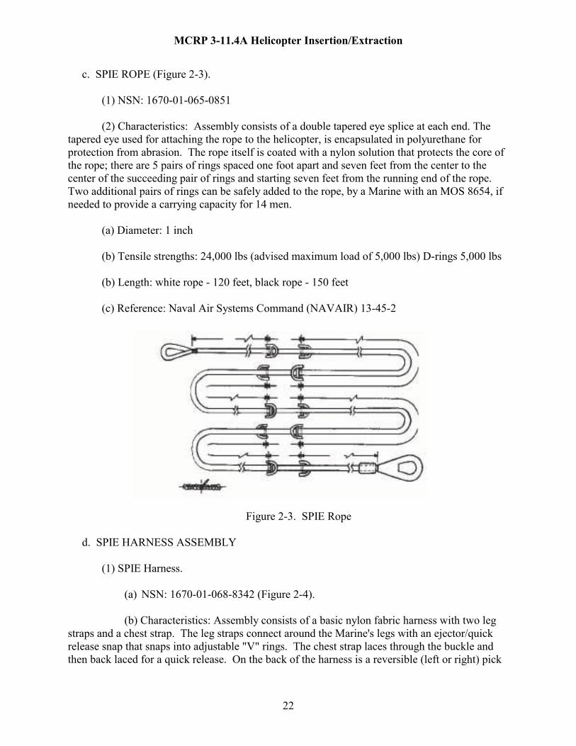
c. SPIE ROPE (Figure 2-3).
(1) NSN: 1670-01-065-0851
(2) Characteristics: Assembly consists of a double tapered eye splice at each end. The tapered eye used for attaching the rope to the helicopter, is encapsulated in polyurethane for protection from abrasion. The rope itself is coated with a nylon solution that protects the core of the rope; there are 5 pairs of rings spaced one foot apart and seven feet from the center to the center of the succeeding pair of rings and starting seven feet from the running end of the rope. Two additional pairs of rings can be safely added to the rope, by a Marine with an MOS 8654, if needed to provide a carrying capacity for 14 men.
(a) Diameter: 1 inch (b) Tensile strengths: 24,000 lbs (advised maximum load of 5,000 lbs) D-rings 5,000 lbs
(b) Length: white rope - 120 feet, black rope - 150 feet
(c) Reference: Naval Air Systems Command (NAVAIR) 13-45-2
Figure 2-3. SPIE Rope d. SPIE HARNESS ASSEMBLY
(1) SPIE Harness.
(a) NSN: 1670-01-068-8342 (Figure 2-4).
(b) Characteristics: Assembly consists of a basic nylon fabric harness with two leg straps and a chest strap. The leg straps connect around the Marine's legs with an ejector/quick release snap that snaps into adjustable "V" rings. The chest strap laces through the buckle and then back laced for a quick release. On the back of the harness is a reversible (left or right) pick
22

MCRP 3-11.4A Helicopter Insertion/Extraction
up strap into which an 85 Stubai carabiner or approved steel locking carabiner is inserted for attachment of the harness to the SPIE rope.
(2) Lightweight SPIE Harness.
(a) NSN: 8465-01-440-5883 (Figure 2-5).
(b) Characteristics: This harness is similar to the existing harness, but is made of lighter materials and eliminates unnecessary hardware, thus reducing weight and bulk.
Figure 2-4. SPIE Harness Figure 2-5 Lightweight SPIE Harness e. CARGO SUSPENSION SLINGS WITH TYPE IV CONNECTOR (Figure 2-6)
(1) NSN: Slings 1670-00-856-0266 Type IV Connector 1670-00-783-5988
(2) Characteristics: The type-26 multi-loop sling comes in multiple lengths. The 9' and 11', two loop, nylon slings are the only ones authorized for HRST for use in SPIE operations. The cargo suspension slings are used as anchor points for the SPIE line. The Type IV connector consists of the body with two steel prongs and a spring loaded top plate.
(3) Tensile strengths: Type-26 multi-loop sling 14,000 lbs Type IV Connector 40,000 lbs
(4) Inspection: Inspection of the cargo slings and Type IV connector is done before, during and after use. Inspect the sling for contamination from oil, grease, acid, or other foreign matter. Look for cuts, fraying, or burn marks on the webbing. If more than three stitches in a row are loose or broken, the sling is unserviceable. Inspect the Type IV connector for cracks, burrs, grooves, flaws and rust. The top plate should be checked to ensure that the spring is functioning properly and locks the retaining plate into place. Remove any rust with steel wool
23

MCRP 3-11.4A Helicopter Insertion/Extraction
and a coating of a light lubricant. Discard all Type IV connectors that have two holes in the bottom plate assembly. Cargo slings should be cleaned by scrubbing with a brush. Wet slings should be dried on a drying rack.
(5) The cargo strap has a service life of seven years and a shelf life of 15 years.
Figure 2-6. Cargo Suspension Sling with Type IV Connector f. RAPPEL ROPE ATTACHMENT CABLES (Figure 2-7).
(1) Characteristics: A 32 inch long steel cable. Each cable incorporates an eyelet on each end. The eyelets are used to attach the cable to the deck rings inside the helicopter. The eyelets are manufactured utilizing thimbles and swedges.
(2) Tensile strength: 2500 lbs when under a load for 2 minutes or less.
(3) Nomenclature: P/N NSN Thimbles AN100-C8 4030-00-262-1894 Cable, steel MIL-W-83420 4030-00-431-5540 Swedges 28-1 of 6 4010-00-222-4479
(4) Uses: As a connection point between the rappel rope and the attachment points in the UH-1N helicopter.
(5) Manufacture: Marine Aviation Logistics Squadron
24

MCRP 3-11.4A Helicopter Insertion/Extraction
Figure 2-7. Rappel Rope Attachment Cable g. STUBAI 85 CARABINER (Figure 2-8).
(1) Model number: STUBAI 85/434005
(2) Characteristics: A steel modified "D" shaped, locking carabiner with a locking nut. The Stubai 85 carabiner is used for all HRST systems.
(3) Tensile strength: STUBAI 5,500 lbs
(4) Inspection: Inspect the Stubai 85 carabiner for burrsand rust. Check that the locking gate springs close and the locking nut secures firmly.
Figure 2-8. Stubai 85 Carabiner
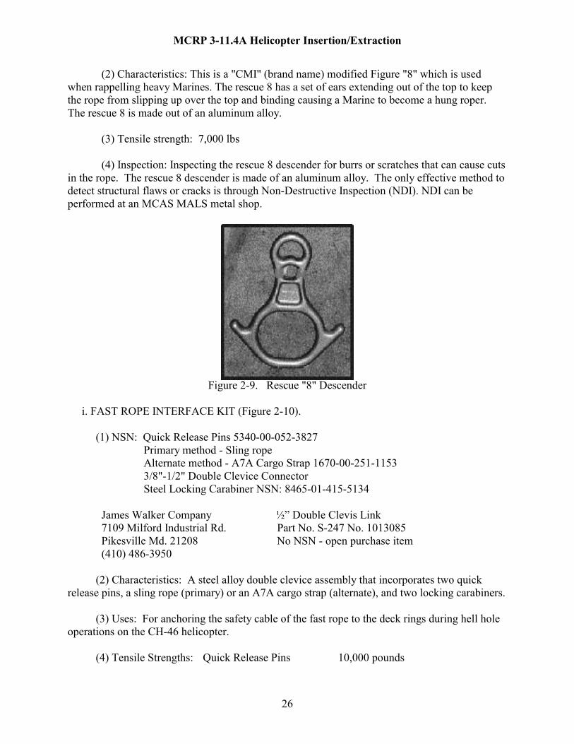
h. RESCUE "8" DESCENDER (Figure 2-9).
(1) NSN: N/A
25
MCRP 3-11.4A Helicopter Insertion/Extraction
(2) Characteristics: This is a "CMI" (brand name) modified Figure "8" which is used when rappelling heavy Marines. The rescue 8 has a set of ears extending out of the top to keep the rope from slipping up over the top and binding causing a Marine to become a hung roper. The rescue 8 is made out of an aluminum alloy.
(3) Tensile strength: 7,000 lbs
(4) Inspection: Inspecting the rescue 8 descender for burrs or scratches that can cause cuts in the rope. The rescue 8 descender is made of an aluminum alloy. The only effective method to detect structural flaws or cracks is through Non-Destructive Inspection (NDI). NDI can be performed at an MCAS MALS metal shop.
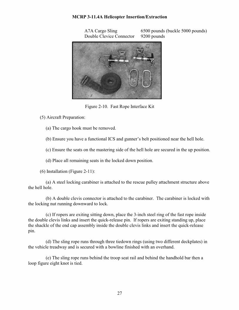
Figure 2-9. Rescue "8" Descender i. FAST ROPE INTERFACE KIT (Figure 2-10). (1) NSN: Quick Release Pins 5340-00-052-3827 Primary method - Sling rope Alternate method - A7A Cargo Strap 1670-00-251-1153 3/8"-1/2" Double Clevice Connector Steel Locking Carabiner NSN: 8465-01-415-5134 James Walker Company ½” Double Clevis Link 7109 Milford Industrial Rd. Part No. S-247 No. 1013085 Pikesville Md. 21208 No NSN - open purchase item (410) 486-3950 (2) Characteristics: A steel alloy double clevice assembly that incorporates two quick release pins, a sling rope (primary) or an A7A cargo strap (alternate), and two locking carabiners. (3) Uses: For anchoring the safety cable of the fast rope to the deck rings during hell hole operations on the CH-46 helicopter. (4) Tensile Strengths: Quick Release Pins 10,000 pounds
26
MCRP 3-11.4A Helicopter Insertion/Extraction
A7A Cargo Sling 6500 pounds (buckle 5000 pounds) Double Clevice Connector 9200 pounds
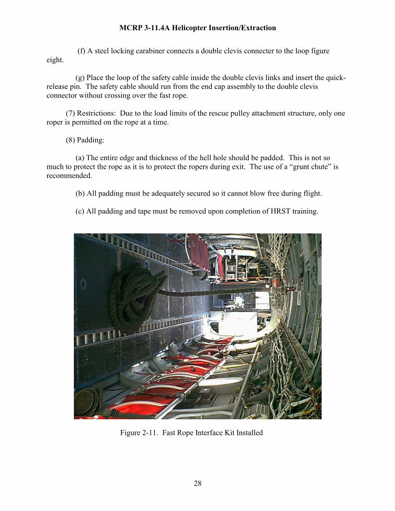
Figure 2-10. Fast Rope Interface Kit (5) Aircraft Preparation: (a) The cargo hook must be removed. (b) Ensure you have a functional ICS and gunner’s belt positioned near the hell hole. (c) Ensure the seats on the mastering side of the hell hole are secured in the up position. (d) Place all remaining seats in the locked down position. (6) Installation (Figure 2-11): (a) A steel locking carabiner is attached to the rescue pulley attachment structure above the hell hole. (b) A double clevis connector is attached to the carabiner. The carabiner is locked with the locking nut running downward to lock. (c) If ropers are exiting sitting down, place the 3-inch steel ring of the fast rope inside the double clevis links and insert the quick-release pin. If ropers are exiting standing up, place the shackle of the end cap assembly inside the double clevis links and insert the quick-release pin. (d) The sling rope runs through three tiedown rings (using two different deckplates) in the vehicle treadway and is secured with a bowline finished with an overhand. (e) The sling rope runs behind the troop seat rail and behind the handhold bar then a loop figure eight knot is tied.
27
MCRP 3-11.4A Helicopter Insertion/Extraction
(f) A steel locking carabiner connects a double clevis connecter to the loop figure eight. (g) Place the loop of the safety cable inside the double clevis links and insert the quick-release pin. The safety cable should run from the end cap assembly to the double clevis connector without crossing over the fast rope. (7) Restrictions: Due to the load limits of the rescue pulley attachment structure, only one roper is permitted on the rope at a time. (8) Padding: (a) The entire edge and thickness of the hell hole should be padded. This is not so much to protect the rope as it is to protect the ropers during exit. The use of a “grunt chute” is recommended. (b) All padding must be adequately secured so it cannot blow free during flight. (c) All padding and tape must be removed upon completion of HRST training.
Figure 2-11. Fast Rope Interface Kit Installed
28
MCRP 3-11.4A Helicopter Insertion/Extraction
j. LEATHER GLOVES (1) NSN: 8415-00-634-4660
(2) Characteristics: Heavy duty, leather, work gloves. Gloves are consumable, and come in several styles, and may be purchased at self- service. Welder’s gloves are recommended for fast rope operations. (3) Rappellers/Fast Ropers may use any other heavy leather gloves if approved by the HRST Master. However gauntlet gloves are not appropriate because the internal padding is positioned to protect the back of the hand and not the palm. k. SLING ROPE (1) Characteristics: A 12-15 foot long piece of rappel rope 11mm in diameter and whipped or burned on each end. (2) Uses: Used to construct military rappel seats and safety lines. l. TAPE (1) May be obtained through self-service. (2) Characteristics: Military green, multi-use, "riggers" or "duct tape”. (3) Uses: To protect ropes and lines at friction points on the helicopter, to secure fire hose or other padding, and many other uses. CAUTION: Oil residues may seriously reduce the adhesive properties of the tape leading to dislodging of the protective system. m. GOGGLES (1) NSN: 8465-01-004-2893 (2) Characteristics: Military, impact plastic with elastic head strap.
(3) Uses: To protect the eyes from sand and other flying debris.
(4) Units will wear appropriate eye protection according to mission requirements. n. ROPE STORAGE BAG (1) NSN: 1670-00-590-9909 (2) Characteristics: Standard military parachute D-bag.
29

MCRP 3-11.4A Helicopter Insertion/Extraction
(3) Uses: Fast rope and SPIE rope Storage.
o. COMMERCIAL RAPPEL HARNESS
(1) Catalog Number: 9113500
(2) Name: Bod Seat
(3) Company: Black Dimond (Note: Not mandatory)
(4) MWTC Harness as an alternate NOTE: Figure and specifications were not available at the time of this draft’s posting on the web page. 2102. AVIATION EQUIPMENT The equipment listed below is provided and maintained by the aviation unit supporting the HRST operation: a. SCHLOMER FRAME (Figure 2-12).
(1) Characteristics: A welded tubular steel frame. Anchor points incorporate three quick release pins capable of collapsing the frame and storing it out of the way when not in use.
(2) Uses: For attaching 1 or 2 fast ropes at the ramp rope station of the CH-46E.
(3) Manufacturer: Intermediate Maintenance Activity (IMA) of the Aviation Group
(4) Installation: The Schlomer frame is installed by the aircrew. (5) Maintenance cycle/ Non Destructive Inspection (NDI) of the Schlomer frame by IMA
is required every 365 days.
Figure 2-12. Schlomer Frame
30

MCRP 3-11.4A Helicopter Insertion/Extraction
b. FAST ROPE GANTRY (Figure 2-13).
(1) Boom Rescue Hoist NSN: 1680-00-120-0541 Base Plate Assembly P/N: 205-072-236-1
(2) Characteristics: A pedestal and boom assembly. Incorporates a base plate for mounting on the aircraft deck. Has a two position locking arm for stowing or positioning for use and a quick release pins for anchoring the fast rope and safety cable.
(3) Uses: For attaching the fast rope at the forward cabin rope station on either side of the UH-1N helicopter (port or starboard). When the two gantry booms are installed, a cargo ratchet strap running around the top of the pedestal will be utilized as a safety back up for all fast rope operations.
(4) Installation: The fast rope gantry is installed by the aircrew.
Figure 2-13. Fast Rope Gantry c. FAST ROPE ANCHOR BAR (Figure 2-14).
(1) Characteristics: An aluminum alloy rectangular bar and two attached quick release assemblies. The anchor bar secures to two permanently installed brackets mounted on each side of the cabin bulkhead.
(2) Uses: For attaching up to two fast ropes at the ramp rope station of the CH-53D helicopter.
(3) Manufacturer: Naval Aviation Depot, NAS Pensacola, FL
31

MCRP 3-11.4A Helicopter Insertion/Extraction
(4) Installation: The fast rope anchor bar is installed by the aircrew.
Figure 2-14. Fast Rope Anchor Bar d. A-FRAME FAST ROPE ATTACHMENT BAR ASSEMBLY (Figure 2-15).
(1) Characteristics: The A-Frame attachment bar assembly consists of a monel sleeve assembly and a peanut link.
(2) Uses: For attaching one fast rope for hell hole operations from the CH-53E.
(3) Manufacturer: Marine Aviation Logistics Squadron (MALS) of the Aviation Group.
(4) Installation: The A-Frame attachment bar assembly is installed by the aircrew.
Figure 2-15. A-Frame Fast Rope Attachment Bar Assembly
32

MCRP 3-11.4A Helicopter Insertion/Extraction
CHAPTER 2
HRST ROPES, EQUIPMENT, TERMINOLOGY, AND KNOTS
SECTION 2: ROPE AND EQUIPMENT MANAGEMENT
2200. GENERAL. The personal safety of all ropers is dependent upon the condition and serviceability of the HRST equipment in use. All caution must be taken to ensure that damaged and unserviceable equipment is not utilized. The management procedures outlined in this chapter are considered the minimum standards allowed. 2201. GROUND EQUIPMENT. The HRST equipment listed below is maintained by the ground unit: a. ROPE MANAGEMENT
(1) A new rope will be physically inspected for any signs of damage or defects. After passing inspection, both ends of the rappel line should be whipped and burnt (Figure 2-16). The free end of the fast rope should be whipped, but not burnt. The unit must store and maintain all HRST ropes in a clean, well-ventilated, dry area in accordance with current directives.
Figure 2-16. End of Rope Whipping
(2) All ropes will be checked before and after every use for wear, cuts, frays, burns, mildew, and rotten areas. (3) All ropes must be kept dry, unless getting wet is unavoidable with use. If the rope should become wet, dry it as soon as possible. Uncoil the rope and lay it in a well ventilated area. If possible suspend the rope off the deck on wooden pegs or a rack to reduce drying time. If any part of the rope comes in contact with any type of petroleum products (i.e. fuel, oil) the
33

MCRP 3-11.4A Helicopter Insertion/Extraction
rope is considered unserviceable as a lifeline and will be taken out of service. All of this will be maintained in a rope log.
(4) Protect nylon rope and webbing from direct sunlight as much as possible to avoid ultraviolet deterioration.
(5) All ropes used in HRST must be free of splices.
(6) Never keep a rappel rope knotted or stretched any longer than necessary.
(7) Never stand, walk, step or smoke around the rope. This can cause a weakening of the rope. If rope does become soiled, shake it clean or rinse it with fresh water and lay it out to dry before storage. Keep all ropes away from petroleum products.
(8) Any rope that is considered defective or unserviceable must be separated from useable rope and tagged with the nature of the defect, the cause, and the date of inspection and signed by an HRST Master.
(9) Rope grading for SPIE and Fast Ropes will emphasize a visual inspection for serviceability. Although fast ropes and SPIE ropes gradually change color, such changes do not indicate a decrease in strength unless the change is due to contact with strong chemicals. Changes in color caused by chemical contamination not be uniform throughout the length of the rope. Visual inspections for both Fast Ropes and SPIE ropes are as follows: SPIE –Check for excessive abrasion, fraying, or one complete strand broken. Inspect D-ring attachment points for corrosion and cracks. Fast Rope – Check for corrosion, cracks and security of the mounting hardware for the head cap assembly. One broken strand on safety cable will render the entire rope unserviceable. There must be a #1 stamped on the swedge crimp securing the safety cable on ropes manufactured prior to 1 Dec 1995. See Figure 2-18.
(10) Any HRST Master has the authority to deadline any rope that they determine to be unserviceable.
ROPE GRADING TABLE: Ropes are classified as Serviceable or Unserviceable
Grade Definition Appearance Used For I. A new rope but not older than Little or no external High rappelling two years or with no more than wear tower/helicopter 300 rappels on it. rappel II. A rope older than two years or Shows slight external Rappelling no with more than 300, but less than wear, furry on outer higher than 30 fee
34

MCRP 3-11.4A Helicopter Insertion/Extraction
600 rappels on it. yarns III. A rope with more than 600 N/A Water work/sling rappels on it. ropes b. All HRST ropes should be coiled when not in use and hung from a wooden peg or cylindrical object. At no time will ropes be hung on any type of metal or steel object because of possible rust. There are two types of coils for rappel ropes mountain coil and butterfly coil.
(1) Mountain Coil (Figure 2-17) least preferred because rope tends to tangle up during uncoiling. Figure 2-17. Mountain Coil
(2) Butterfly Coil (Figure 2-18) most preferred because it tangles less and can be tied across the back. Figure 2-18. Butterfly Coil
c. SPIE and Fast Ropes. When coiling the rope, avoid knots and entanglements and provide maximum ventilation to the rope surface. Place SPIE and fast ropes in parachute kit bags for protection when not in use.
35

MCRP 3-11.4A Helicopter Insertion/Extraction
*IMPORTANT NOTE: ALL FAST ROPES MANUFACTURED PRIOR TO DEC 95 MUST BE RECRIMPED AND MUST CONTAIN THE ROMAN NUMERAL “I” STAMPED INTO THE SWEDGE TO BE CONSIDERED SERVICEABLE. THE CRIMPING IS DONE ON THE SAFETY CABLE’S TOP SWEDGE HOLDING THE EYE SPICE. ANY ROPE WITHOUT THIS STAMP WILL NOT BE USED FOR HRST OPERATIONS UNTIL THE ROPE IS RECRIMPED. FOR ACCESS TO THE CRIMPING DEVICE, CONTACT MARFORLANT MMO.
Figure 2-19. Fast Rope Crimp d. HRST ropes and SPIE equipment stowage:
(1) Keep ropes and equipment at least four inches from walls when stored on shelves.
(2) Keep ropes and equipment at least 12 inches from the floor when stored in bins.
(3) Storage areas should be well ventilated and free from oil, acid, cleaning compounds and other contaminants.
(4) Do not stow ropes and equipment above or near hot water pipes, heating apparatus, or direct sun light. e. Inspect harness and suspension sling webbing for signs of contamination from oil, grease, acid, and rust. Inspect for signs of wear such as cuts, twists, fading, fusing, fraying, burns, abrasions, and loose or broken stitches. A damaged harness or suspension sling shall be removed from service and returned to supply for appropriate disposition. In addition, inspect all
36
MCRP 3-11.4A Helicopter Insertion/Extraction
hardware for corrosion, pitting, ease of operation, security of attachment, bends, dents, nicks, and sharp edges. Replacement of hardware which requires unstitching of webbing shall render the entire harness, except chest strap adapter, unserviceable. Replacement of "V-ring" shall be accomplished by cutting the section of the leg strap. If damaged, return the harness suspension sling to supply for appropriate disposition. f. The SPIE system shall be inspected by a qualified HRST Master at six month intervals and when serviceability is questioned. . Using units will comply with service life limitations contained in NAVAIR 13-45-2. This will be documented in the rope log book. g. Steel Locking Carabiner: The locking D-ring, steel carabiner is made of lightweight steel. The heating of the carabiner by the rappel line can cause fatigue of the carabiner making it less reliable after numerous rappels. It is difficult to record the number of rappels on use, with emphasis on the locking gate mechanism and hinge pin. If excessive play is found in the hinge mechanism, discard the carabiner through appropriate supply channels. The defective carabiner should be marked or cut in half to prevent its use. 2202. AVIATION EQUIPMENT. The HRST equipment listed below is placed in the custody of and maintained by the aviation element. a. Schlomer Frame. The Schlomer frame is manufactured at the Intermediate Maintenance Activity (IMA) of the aircraft group. It is fabricated from quality materials, serialized, and placed on a support equipment inspection cycle.
(1) The IMA will maintain the frame as an accountable piece of support equipment. A serial number will be etched and/or stamped on top of the frame above the quick release pins.
(2) The frame shall undergo a non-destructive inspection (NDI) at the completion of 500 descents or at the end of a six month inspection cycle, which ever occurs first. The frame shall be inspected for:
(a) Condition of all hardware (i.e. pins, cables) (b) Condition of all welds for signs of cracks or fatigue.
(c) Condition of steel tubing for signs of buckling, bending, rust, or deformation.
(d) Conduct a Magnetic Particle Inspection for cracks, fatigue, and stress at all joints, welds, and stress points.
(3) Repair and re-inspect any discrepancies or reject the bad frame.
(4) The Schlomer Frame’s history will be recorded on a Custody and Maintenance Record. This will be maintained by the aircraft squadron.
37

MCRP 3-11.4A Helicopter Insertion/Extraction
b. Fast Rope Gantry. The fast rope gantry and base plate assembly are modified from the UH-1 rescue hoist boom.
(1) Once modified for fast rope use, the gantry shall be marked "FOR FAST ROPE ONLY".
(2) The aircraft group shall maintain the gantry as an accountable piece of support equipment. The gantry's history will be recorded on a Custody and Maintenance Record.
(3) Unless suspected of being damaged, the gantry shall follow the original maintenance inspection cycle established for the rescue hoist boom and base plate assembly.
38

MCRP 3-11.4A Helicopter Insertion/Extraction
CHAPTER 2
HRST ROPES, EQUIPMENT, TERMINOLOGY, AND KNOTS
SECTION 3: HRST TERMINOLOGY AND KNOTS 2300. GENERAL. The HRST terminology and knots contained in this section are designed to provide a basic understanding for all HRST members. This section is not intended nor is it designed to teach the basics of rope skills. 2301. HRST TERMINOLOGY. The terms defined below are utilized in connection with HRST: a. Belay/Brake. In HRST, a method to control or stop the uncontrolled descent of a roper. b. Bight. A bend in the rope that does not cross itself. c. Fast Rope. A technique that inserts Marines into small areas from a helicopter. The ropers slide down the rope and are not attached to it. d. Figure "8" Assault Descender. An aluminum-alloy device which roughly resembles the numeral "8". A descender is used when rappelling with heavy loads. e. Line. An 11mm diameter rope used in rappelling f. Loop. A bend in the line/rope in which the line/rope crosses itself. g. Helicopter Rope Suspension Training (HRST) Master. A Marine trained and certified to instruct rappelling, fast rope and SPIE operations. h. Fast Rope Landing (FRL). A landing technique used to prevent injury during a rapid decent while fast roping, as described in paragraph 3202.f(10). i. Rope Station. The point on a static tower or helicopter where ropers are expected to execute their descent. j. Round Turn. Wrapping the rope around a specific object such as a post, rail, or pipe so that it has 360 degrees contact. The running end leaves the object in the same direction as the standing end. k. Running End. The free or working end of the rope. l. Sling Rope. An 11mm rappel line approximately 12-15 feet long, whipped and burned on both ends. It is used to construct the Rappel Seat and Safety Harness.
39

MCRP 3-11.4A Helicopter Insertion/Extraction
m. Carabiner. A "D" shaped steel ring with a gate on one of its sides. The gates are either locking or non-locking. It is also referred to as a snaplink or Stubai. n. SPIE. Special Patrol Insertion/Extraction is a method to insert and/or extract troops by helicopter from water or rough terrain conditions. o. Standing End. The end of the line or rope secured to an anchor point or the end that is static. p. Stick. A number of Marines entering or exiting the aircraft together. q. Webbing. This is essentially a flat rope made of nylon or polyester. Its most common usage is for slings and harnesses. The sizes used most often are 1" and 2" webbing. It is made in two forms; flat and tubular. r. Whipping. A wrapping or binding of light cord on the end of a line to prevent it from unraveling. s. Practice coil. An extended sling rope 15-20 feet long. t. Pigtails. The short length left at the end of a rope after tying a knot or coiling a rope. 2302. HRST KNOTS. All knots used by the roper fall into four categories: (1) end of the rope knots, (2) anchor knots, (3) middle of the rope knots, and (4) specialty knots. The matrix below describes the standards and requirements for completing the HRST Course. END ROPE I ANCHOR II MIDDLE OF SPECIAL KNOTS ROPE III IV Square Bowline Figure 8 (30 sec) Directional (45 sec) Knot (30 sec) with overhand for two knots (30 sec) Water Tape Clove Hitch Around body Bowline (30 sec) (30 sec) with figure 8 (45 sec) Bowline Around Four finger Prusik Object with Bowline (45 sec) (30 sec) Round turn and two Rappel Seat with Carabiner half hitches (30 sec) (60 sec) Note: ALL PIGTAILS WILL NOT EXCEED 4”– 6”
40

MCRP 3-11.4A Helicopter Insertion/Extraction
(a) Testing Standards (1) All knots will be mastered with a 100% for passing a knot test. (2) All written tests will be considered passing with a score of 80% per
Marine Corps order. (3) All knots will be done without a blindfold.
(b) Rigging Time Standards (1) All Tower rigging will be an 8 minute limit. (2) All Aircraft rigging will be an 8 minute limit. (3) Mastering will be considered a Go/No Go criteria.
(c) Retest Specifications
(1) Knots- Same day retest but the Marine will only have to retest the knot he failed and be graded by a different instructor.
(2) Written tests- Next day retest, although they will take a different test. (3) Rigging systems- Any three rigging failures acquired by the student
will constitute as a drop in the course. One retest will be permitted per system failure.
a. End of the Rope Knots.
(1) Square Knot. This knot is used to join two ropes of equal diameter together. It will be secured on each side by an overhand knot (Figure 2-20).
Figure 2-20. Square Knot b. Anchor Knots
(1) Bowline. Used to secure the end of the rope to an object/anchor point. The pigtail must be inside and secured with an overhand (Figure 2-21).
41

MCRP 3-11.4A Helicopter Insertion/Extraction
Figure 2-21. Bowline Knot
(2) Clove Hitch. Used to secure a rope to a round/cylindrical object (trees, poles, pipes, etc.). It is an equal tension knot (Figure 2-22). Figure 2-22. Clove Hitch c. Middle of the Rope Knots
42

MCRP 3-11.4A Helicopter Insertion/Extraction
(1) Figure "8" Loop. This knot forms a single bight and is used as an anchor in the middle or end of the rope. It retains 80% of its tensile strength. 8's are the preferred knots (Figure 2-23).
Figure 2-23. Figure "8" Loop d. Specialty Knots
(1) Overhand Knot. This knot is used to secure other knots when used as a secondary/safety knot for the primary knot (Figure 2-24).
Figure 2-24. Overhand Knot
(2) Multi Directional, End of the Line Prusik. This knot will move freely along a fixed
rope until tension is applied to it; it will then lock in place. It can be used as a safety/retrieval Line (Figure 2-25).
43

MCRP 3-11.4A Helicopter Insertion/Extraction
Figure 2-25. Multi Directional Prusik (3) Directional Figure "8" Loop. This forms a single, fixed loop that can be tied so that the loop faces either the standing end or the running end. It may be used as a primary and secondary anchor (Figure 2-26).
Figure 2-26. Directional Figure "8" Loop
(4) Military Rappel Seat. Fashioned from the sling rope, start by taking the center of the sling rope and placing it on the left hip so that the running ends of the rope wrap around the waist just below the hipbone. Next, bring both ends together in front of the body and tie an overhand knot in front (preferably two). Take the two running ends down between the legs and bring them up behind you. Bring the two running ends down through the legs up over the buttocks, and over the original waist wrap and the waist. Then bring the rope over itself forming a bight then, cinch this up tightly. Also, make sure the ropes run along the outside of the buttocks. Take the two running ends and make a square knot with two overhands on the left hip. Any loose rope from the square knot will be tucked into a pocket (Figure 2-27).
44

MCRP 3-11.4A Helicopter Insertion/Extraction
Figure 2-27. Military Rappel Seat
(5) Around The Body Bowline. This is used as a secondary anchor point for SPIE rigging and also as a safety line for HRST operations (Figure 2-28). Figure 2-28. Around the Body Bowline
45

MCRP 3-11.4A Helicopter Insertion/Extraction
CHAPTER 3
HRST TRAINING
PARAGRAPH PAGE SECTION 1: STATIC TOWER TRAINING GENERAL 3100 47 STATIC TOWER REQUIREMENTS 3101 47 CONDUCT OF TRAINING 3102 49 SECTION 2: HELICOPTER TRAINING GENERAL 3200 53 HELICOPTER TRAINING REQUIREMENTS 3201 53 FIGURES 3-1 STATIC TOWER TRAINING 47 3-2 THREE ANCHOR POINTS 48 3-3 THE "L" POSITION 50
46

MCRP 3-11.4A Helicopter Insertion/Extraction
CHAPTER 3
HRST TRAINING
SECTION 1: STATIC TOWER TRAINING 3100. GENERAL. The introduction to HRST shall be taught on a static tower. Utilizing the "building block approach" to training. Marines shall systematically progress to more demanding platforms including taller static towers and finally helicopters. The static tower in use may vary in size and height (30-90 feet). The concept of learning the basics of HRST techniques prior to helicopter operations does not vary (Figure 3-1). Figure 3-1. Static Tower Training 3101. STATIC TOWER REQUIREMENTS
a. Training Phases. The 30 foot tower is used for the Marine's introduction to rappelling and for refresher training. Each phase of rappel training should begin on a walled surface. These phases include rappel/fast rope without gear, rappel/fast rope with gear, and night rappel/fast rope training with and without gear. HRST from helicopters can also be taught by utilizing the helicopter skid mock-up that may be mounted on the tower. The figure "8" rappel may be taught when figure "8" assault descenders are available. b. Safety Personnel. The following personnel and equipment are required to be present during all static tower training.
47

MCRP 3-11.4A Helicopter Insertion/Extraction
(1) Two military rappel lines are required per rope station.
(2) One certified SIO.
(3) One HRST Master per rope station.
(4) One Corpsman with Unit 5, cervical collar, and backboard. The Corpsman will not participate as a roper during HRST training.
(5) One safety vehicle with driver. The driver will not participate as a roper during HRST training.
(6) One belay man per rope station. Ropers will alternate stations. c. Static Tower Preparation
(1) All rope stations will be rigged with three (3) anchor points (Figure 3-2) using the appropriate knots. All anchor points must be certified as being load tested to 5,000 pounds. Note: all towers are designed differently and require the use of different anchor knots. Take all slack out between knots to create equal tension on all three anchor points. A maximum of ten feet of rope will be on the deck during static tower rappelling to minimize the possibility of the rope being stepped on. Figure 3-2. Three Anchor Points
48

MCRP 3-11.4A Helicopter Insertion/Extraction
d. Static Tower Inspection. The HRST Master is in charge of the tower. He is responsible for visually and physically inspecting the tower using the standards provided in appendix E prior to conducting tower training. e. Safety Procedures
(1) The static tower will not be utilized during rain, thunderstorms, or excessively high winds. If ice is present or if the platform is slick from rain, the HRST operation will be delayed until conditions are safe.
(2) There will be only one roper on each ladder at any given time, he will not wear gloves or carry anything in his hands.
(3) The HRST Master or SIO will determine how many ropers per rope station is safe.
(4) HRST Masters and SIOs must be aware of ropers who appear to be experiencing uneasiness towards heights. Ropers will only be trained to their confidence level.
(5) HRST Master or SIO will re-inspect all individuals equipment for proper donning and serviceability prior to the roper ascending the tower and prior to descending the rope.
(6) The HRST Master will be secured to the tower with a safety line. The length of the safety line will not exceed the amount necessary to perform his duties.
(7) At no time will a roper descend the rope without proper gloves and a helmet.
(8) At no time shall any member step on a rope.
(9) No bounding will be permitted due to the stress that will be placed on the ropes and anchor points. 3102. CONDUCT OF TRAINING a. Safety Brief. Prior to commencement of any training, the HRST Master shall conduct a safety brief with personnel that will include:
(1) Static tower safety
(2) Static tower commands
(3) Proper roping techniques b. Demonstration. After explaining the procedures to all ropers, the HRST master will have an assistant demonstrate one complete cycle of the static tower so that all ropers can hear all of the proper commands and see the actions and proper techniques used on the static tower.
49

MCRP 3-11.4A Helicopter Insertion/Extraction
c. Climbing the Tower
(1) Before climbing the ladder, each roper will have his equipment checked by an HRST Master or SIO.
(2) The roper will kick any sand off his boots prior to climbing.
(3) When possible, the roper will grasp the outside of the ladder not the rungs, while climbing.
(4) Just prior to climbing the ladder, the roper will sound off with his name "__________ climbing" and then begin the climb up the ladder. Once at the top and clear of the ladder, the roper will sound off, "ladder clear.” The roper will then wait for the HRST Master to direct him to proceed to a rope station. At this time, the next roper in line may start to climb the ladder. d. Tower Procedures
(1) Once directed to a rope station, the HRST Master will ensure proper hook up for rappelling or proper grasping for fast rope operations.
(2) While maintaining his brake, the roper on command from the HRST Master will step to the edge and face the anchor point. At this time the roper will sound off last name "_________ ON RAPPEL". The belay man will respond with last name "________ ON BELAY.”
(3) On direction from the HRST Master, the roper will assume the "L" shape position (Figure 3-3). On the command "GO" from the HRST Master, the roper will then begin his descent. Figure 3-3. "L" Position
(4) The belay man will wrap the running end of the rope around his waist. If the roper loses control, the belay man will position the running end of the rope in his chest and run backwards to stop the roper from falling. At NO time will the belay man wear gloves and must keep his eyes on the roper at all times.
50

MCRP 3-11.4A Helicopter Insertion/Extraction
(5) Once the roper is on the ground, the belay man will grab the rope in front of the roper and hold it as the roper walks backwards. The roper’s hands will be placed above the carabiner to prevent from being hit in the face with the end of the rope.
(6) Once clear of the rope, the roper sounds off his name "_____________ OFF RAPPEL." At the same time, he places his hands on top of his head.
(7) Once the roper has cleared the rope, the belay man sounds off his name "___________ OFF BELAY". e. Helicopter Skid Rappel. The helicopter skid rappel prepares students to rappel from a UH-1N helicopter. The roper is hooked up while he sits on the platform just above the helicopter skid. After sounding off and on command, the roper steps out onto the skid, turns around, and assumes an "L" shape position (Figure 3-3). On command the roper will push out and descend. The HRST Master is responsible for the proper procedures and safety. f. Tower Fast Rope Procedures.
(1) Once directed to a rope station by the HRST Master, the roper will assume a seated or standing position. The HRST Master will ensure positive control of roper is maintained until the individual roper has engaged the fast rope. (2) The HRST Master will ensure proper safety equipment is donned by the individual ropers. He will then direct the roper to engage the fast rope with the voice command “Feet, Hands”(for a seated fast rope descent) or “hands for a standing fast rope execution.
(3) On command from the HRST master, the roper will approach the fast rope and grasp it with both hands and feet. “Never jump for a rope.”
(4) The HRST Master will tap the roper on the back of the head while giving the voice command “Go.”
(5) The individual roper will execute a 45 to 90 degree turn and descend the rope.
(6) While executing a fast rope, keep hands at face level. Adjust rate of descent by hand, knee, and foot pressure on the rope. (NOTE: The roper does not descend hand-over-hand; the rope slides through gloved hands).
(7) During descent the roper will be looking down at the ground and the ropers below them. (8) Do not wrap feet and legs around the rope. Let them hang with the rope passing between the arches of the feet. (9) If the hands start burning, DO NOT let go of the rope. Apply more hand, feet and knee pressure.
51

MCRP 3-11.4A Helicopter Insertion/Extraction
(10) Ropers will execute a fast rope landing. At approximately 3-5 feet from the ground, the roper will spread his legs roughly shoulder width apart, keeping his knees slightly bent to absorb the landing. If the landing is poorly executed and the roper falls to the ground, he will immediately let go of the rope and roll out of the landing area.
(11) A minimum of 10 to 20 feet of rope shall remain on the ground at all times to assist in anchoring the running end of the rope.
(12) The roper will execute descents at speeds commensurate with their experience and proficiency in fast rope operations. A “building block approach” will be used at all times.
(13) The HRST Master will ensure a minimum of ten feet of interval between personnel on the fast rope.
(14) During descent individual ropers may “ LOCK IN” to preclude landing on a fallen roper by standing on the fast rope. This is easily accomplished by sliding one foot on the top of the other with the rope placed between the feet. A “wringing” action with the hands on the rope will assist in a positive “LOCK IN”.
(15) During night fast rope operations, NVGs will not be worn by individual ropers due to limited depth perception and tunnel vision effect.
52

MCRP 3-11.4A Helicopter Insertion/Extraction
CHAPTER 3
HRST TRAINING
SECTION 3: HELICOPTER TRAINING 3200. GENERAL. Those personnel who have met the proficiency requirements of HRST from the static tower and have the recommendation of the HRST Master in charge of the static tower training phase, may progress forward to the helicopter rope suspension training phase. 3201. HELICOPTER TRAINING REQUIREMENTS a. Prerequisites. No roper shall be allowed to conduct HRST from a helicopter without having completed the following tasks with a qualified HRST master present:
(1) Tie a correct military rappel seat.
(2) Demonstrate a proper belay.
(3) Demonstrate proficiency on the static tower in both rappelling and/or fast rope operations.
(4) If conducting night HRST from a helicopter, all of the prerequisites listed above shall be conducted from a static tower at night with proper signals. b. Responsibilities. Specific responsibilities for HRST are contained in detail in Chapter 1. The following responsibilities are general in nature as they apply to helicopter operations. Prior to HRST operations from a helicopter, the HRST Master will provide the following instruction to HRST members:
(1) Hook up procedures inside the aircraft.
(2) Attachment of ropes and carabiner.
(3) Seating.
(4) Exit sequence and belays between individuals/teams/sticks.
(5) Procedures for retrieving/releasing ropes.
(6) HRST commands/signals.
(7) Emergency procedures.
c. Rigging. Rigging for specific aircraft is contained in chapters 4 through 7. The
53
MCRP 3-11.4A Helicopter Insertion/Extraction
following four guidelines are common to rigging any aircraft:
(1) During rigging, the aircraft must be double checked for slick areas and padding against sharp edges.
(2) Follow standards set forth for specific aircraft as detailed in chapter 4.
(3) Double lines will be utilized for all training.
(4) Always close and lock caribiner and secure the knots to the carabiner in the tie down rings.
54
MCRP 3-11.4A Helicopter Insertion/Extraction
CHAPTER 4
RAPPELLING OPERATIONS PARAGRAPH PAGE SECTION 1: HELICOPTER RAPPELLING PROCEDURES GENERAL 4100 56 RAPPEL METHODS 4101 56 SEQUENCE OF EVENTS 4102 59 SECTION 2: AIRCRAFT RIGGING GENERAL 4200 64 RIGGING THE UH-1N 4201 64 RIGGING THE CH-46E 4202 67 RIGGING THE CH-53 D/E 4203 69 FIGURES 4-1 HELICOPTER RAPPELLING 56 4-2 SEAT HIP RAPPEL 57 4-3 BELAY MEN 59 4-4 UH-1N CARGO DECK RING LAYOUT 65 4-5 UH-1N RAPPEL ANCHOR POINTS 66 4-6 CH-46E RAPPEL RAMP STATION ANCHOR POINTS 67 4-7 CH-46E HELL HOLE STATION ANCHOR POINTS 68
55

MCRP 3-11.4A Helicopter Insertion/Extraction
CHAPTER 4
RAPPELLING OPERATIONS
SECTION 1: HELICOPTER RAPPELLING PROCEDURES 4100. GENERAL. Rappelling is the technique used to lower oneself down a rope quickly. Rappelling from a hovering helicopter is a means of insertion when terrain, vegetation, or the tactical situation do not allow for landing. Rappelling also has applications in an urban environment. Rappelling offers an option to the commander when fast rope equipment is not available. With very few exceptions (heavy load 100-120 lb packs), the rappelling techniques and procedures outlined in this section apply to all types/models of helicopters (Figure 4-1).
Figure 4-1. Helicopter Rappelling. 4101. RAPPEL METHODS a. Mission Aircraft. Rappelling can be conducted from the following USMC aircraft:
(1) UH-1N.
(2) CH-46E.
(3) CH-53D/E
56
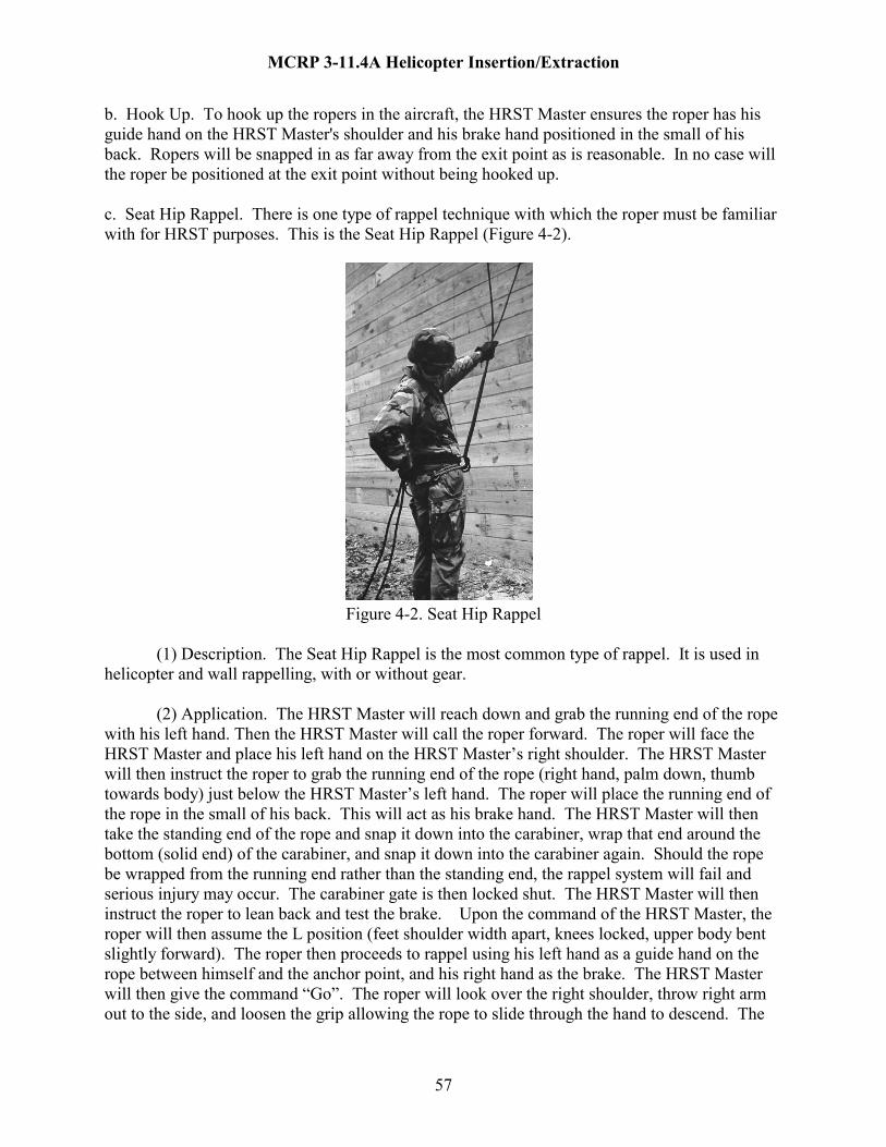
MCRP 3-11.4A Helicopter Insertion/Extraction
b. Hook Up. To hook up the ropers in the aircraft, the HRST Master ensures the roper has his guide hand on the HRST Master's shoulder and his brake hand positioned in the small of his back. Ropers will be snapped in as far away from the exit point as is reasonable. In no case will the roper be positioned at the exit point without being hooked up. c. Seat Hip Rappel. There is one type of rappel technique with which the roper must be familiar with for HRST purposes. This is the Seat Hip Rappel (Figure 4-2).
Figure 4-2. Seat Hip Rappel
(1) Description. The Seat Hip Rappel is the most common type of rappel. It is used in helicopter and wall rappelling, with or without gear.
(2) Application. The HRST Master will reach down and grab the running end of the rope with his left hand. Then the HRST Master will call the roper forward. The roper will face the HRST Master and place his left hand on the HRST Master’s right shoulder. The HRST Master will then instruct the roper to grab the running end of the rope (right hand, palm down, thumb towards body) just below the HRST Master’s left hand. The roper will place the running end of the rope in the small of his back. This will act as his brake hand. The HRST Master will then take the standing end of the rope and snap it down into the carabiner, wrap that end around the bottom (solid end) of the carabiner, and snap it down into the carabiner again. Should the rope be wrapped from the running end rather than the standing end, the rappel system will fail and serious injury may occur. The carabiner gate is then locked shut. The HRST Master will then instruct the roper to lean back and test the brake. Upon the command of the HRST Master, the roper will then assume the L position (feet shoulder width apart, knees locked, upper body bent slightly forward). The roper then proceeds to rappel using his left hand as a guide hand on the rope between himself and the anchor point, and his right hand as the brake. The HRST Master will then give the command “Go”. The roper will look over the right shoulder, throw right arm out to the side, and loosen the grip allowing the rope to slide through the hand to descend. The
57
MCRP 3-11.4A Helicopter Insertion/Extraction
roper must ensure that all loose clothing near the carabiner is tucked in tightly to prevent it from becoming entangled in the carabiner. A left-hand wrap for the left-handed rappel is not authorized. All ropers will brake with the right hand. d. Rope Deployment Methods. There are two examples of deployment methods:
(1) Circular Loop. Coil the rope in a round coil as it is being placed in the waterproof bag. Make sure to coil from running end first, finishing at the standing end. DO NOT tie any knots at end of the rope or secure the rope to the bag in any fashion.
(2) Rope Deployment Bag. The rope deployment bag is used to deploy the rope in an orderly manner The rope is back stacked into the bag in an "S" type manner starting with the running end and working to the standing end. DO NOT tie or secure the rope to the deployment bag in any way. e. Rope Weights
(1) Attaching a weighted object to the running end of any rope is prohibited. Objects attached to a rope could prevent a roper from freeing himself from the rope in the event of an emergency.
NOTE: A chem light will be added to the rappel line at night and removed by the first roper to help determine where the ground is.
(2) A sufficient length of rope in contact with the ground can act as a weight to assist in counteracting the effects of rotor downwash. A minimum of 20 feet of rope in contact with the ground is recommended. f. Belay Men. Personnel on the ground or belay men should hold ropes to keep them steady for ropers. When belaying out of helicopters, the belay man should position himself under the exit point so as not to inadvertently slow or stop the roper prematurely (Figure 4-3). g. Roper Responsibilities:
(1) Understand and comply with all aspects of HRST and emergency procedures. (2) Ensure all safety equipment is properly donned and inspected by a HRST Master. (3) Ensure seat belts are hooked-up prior to take off and unbuckling only on command by the HRST Master. (4) Maintain eye contact with the HRST Master at all times prior to beginning a descent. (5) Make deliberate movements toward the rope station while maintaining a hand hold in the aircraft at all times, and mounting the rope only on the HRST Master’s command.
58

MCRP 3-11.4A Helicopter Insertion/Extraction
(6) Grasp ropes firmly when directed by the HRST Master. (7) Control descent speeds and brake two thirds of the distance down to avoid injuring yourself. (8) Look down at the ground while descending. (9) Move rapidly away from the rope upon landing.
Figure 4-3. Belay Men 4102. SEQUENCE OF EVENTS a. CH-46E - Hell Hole Rappel: NOTE: (HRST Master’s ICS calls are in bold print) (1) Load on signal from the crew chief and inspect the installation of the rappel rope. (2) Don your gunner’s belt and perform an ICS check. “ICS check”. Once the pilot responds, acknowledge his response by letting him know how you hear him. “I have you loud and clear” or “I have you the same” or “I have you weak”. (3) Once all roper’s are seated and strapped in, notify the crew chief that you are all set to begin. “Ropers are ready”. The crew chief will then clear the pilot for lift.
59

MCRP 3-11.4A Helicopter Insertion/Extraction
(4) After take-off, the ropers shall remain strapped in, and the HRST Master shall remain oriented through periodic updates from the HAC. Once the HAC gives the “2-minutes” time warning, the HRST Master responds, “Roger, 2 minutes”. At this time the HRST Master will hold up two fingers and each roper will hold up two fingers on each gloved hand and repeat “2 minutes”. This gives the HRST Master a chance to verify that all roper’s have their helmets, eye protection, and gloves on and that they are awake and ready to go. (For hell hole operations, the crew chief will then assist the HRST Master by opening the hell hole door.) NOTE: AT NO TIME WILL THE HRST MASTER LEAVE AN OPEN ROPE STATION UNATTENDED. (5) The HAC will give the “1-minute” call, the HRST Master will respond. “Roger, 1 minute”. The HRST Master will then give the “1 minute” command to the ropers using hand and arm signals. Ropers should make final checks of all gear. (6) The HAC will give the command “Deploy rope”, the HRST Master will respond. “Roger, deploy rope”. Once the aircraft is in a stable hover and you can see the target directly below you, you may deploy the rope. (7) Once you have verified that the rope is unfouled, on the deck and on target, tell the HAC “Rope on the deck”. Give the following commands to the roper, “Unbuckle”, “Take Position” using hand and arm signals. These commands will be directed to one roper. All others will remain seated and strapped in until told to unbuckle and take position. (8) Ensure you physically control the roper to prevent him from losing his balance and falling out of the aircraft. Maintain this control until you send him out and the roper begins his descent down the rope. (9) Once you have connected a roper to the rope, tell the HAC, “Man on rope”. Verify belay man is set (unless self belay system being used). (10) Direct your roper to the exit point and have him assume the hanging or sitting position over the hell hole. Assist the roper to clear his gear. As he lowers himself through the hell hole, tell the HAC, “Man out”. Monitor the roper all the way to the deck. Once he reaches the deck, tell the HAC, “Man on deck”. When the ropers does a side straddle hop, tell the HAC, “Man off rope”. (11) Continue on with remaining ropers. Ensure after each roper is on the deck that the belay man is reset before you send out the next roper. (12) Once the last man is on the rope, tell the HAC, “Last man on rope” and when completed “Last man off rope”, “Rope being pulled to the # clock position”, which ever was briefed, or “Rope retrieved”, or “Rope jettisoned”.
60

MCRP 3-11.4A Helicopter Insertion/Extraction
HRST MASTER HAC ROPERS Load on command Sit down and buckle in Inspect rigging & Don gunner’s belt “ICS check” Acknowledge
ICS check
“I have you loud and clear” “Ropers are ready” “2 minutes” “Roger, 2 minutes” To ropers, “2 minutes”, & hand/arm signal Repeat “2 minutes” & hand/arm
signal Visually inspect helmets/goggles/gloves “1 minute” “Roger, 1 minute” To ropers, “1 minute”, & hand/arm signal Repeat “1 minute” & hand/arm
signal, make final checks of all gear
“Deploy rope” “Roger, deploy rope”, Deploy rope, inspect if unfouled
“Rope is on the deck” To roper, “Unbuckle”,” Take position” Get into position as directed Connect roper, “Man on rope” verify belay man set.
To roper “Go”, To HAC ”Man out” Roper descends “Man on deck”, ”Man off rope” Roper unhooks, does side
straddle hop, assumes belay after removing gloves.
Continue as the first roper was mastered. “Last man on rope”, ”Go”, ”Man out”, “Man on deck”, “Last man off rope”
“Rope is at the # clock position”/”Rope jettisoned”/Rope retrieved”
b. CH-46E/CH-53D/E – Ramp Rappel: NOTE: (HRST Master’s ICS calls are in bold print) (1) All steps are identical to those used in the hell hole rappel, up to “Unbuckle”. At the command of “Take position”, the roper will come to the HRST Master at the ramp hinge. You will then hook the roper into the system, physically controlling the roper to the edge of the ramp, and verify the belay man is set (unless a self belay system is being used). Direct the roper to assume the “L position” over the edge. You will continue giving the roper the “L” until you are ready to send him. At that point, give him the “Go” hand and arm signal. The roper will bound out away from the aircraft and start his rappel. Tell the HAC, “Man out”. Monitor the roper all
61

MCRP 3-11.4A Helicopter Insertion/Extraction
the way to the deck. Tell the HAC, “Man on deck”. When the roper does a side straddle hop, tell the HAC, “Man off rope”. (2) Continue on with remaining ropers. Ensure after each roper is on the deck that the belay man is reset before you send out the next roper. (3) Once the last man is on the rope, tell the HAC, “Last man on rope” and when completed “Last man off rope”, “Rope being pulled to the # clock position”, which ever was briefed, or “Rope retrieved”, or “Rope jettisoned”. HRST MASTER HAC ROPERS Load on command Sit down and buckle in Inspect rigging & Don gunner’s belt “ICS check” Acknowledge
ICS check
“I have you loud and clear” “Ropers are ready” “2 minutes” “Roger, 2 minutes” To ropers, “2 minutes”, & hand/arm signal Repeat “2 minutes” &
hand/arm signal Visually inspect helmets/goggles/gloves “1 minute” “Roger, 1 minute” To ropers, “1 minute”, & hand/arm signal Repeat “1 minute” & hand/arm
signal, make final checks of all gear
“Deploy rope” “Roger, deploy rope”, Deploy rope, inspect if unfouled
“Rope is on the deck” To roper, “Unbuckle”,” Take position” Get into position as directed Connect roper, “Man on rope” verify belay man set.
To roper “L”, “Go”, to HAC ”Man out” Roper descends “Man on deck”, ”Man off rope” Roper unhooks, does side
straddle hop, assumes belay after removing gloves.
Continue as the first roper was mastered. “Last man on rope”, “L”, ”Go”, ”Man out”, “Man on deck”, “Last man off rope”
“Rope is at the # clock position”/”Rope jettisoned”/Rope retrieved”
62
MCRP 3-11.4A Helicopter Insertion/Extraction
c. CH-46E – Crew Door Rappel: All steps are basically identical to those of the ramp except for the following: (1) You will block the opening of the door prior to hooking up the roper, and then hook the roper in. (2) You will need to physically control each roper out to the bottom step of the crew door or the edge of the aircraft (if it is removed). Note: The sequence of commands is the same as the ramp rappel. d. UH-1N – Skid Rappel: (1) All steps are basically identical to those of the ramp rappel except the HRST Master will be kneeling at the edge of the aircraft cabin and the ropers will be sitting in their pre-briefed position. (2) You will connect a safety line to the roper before he unbuckles. After the roper is connected to the rappel line, you will disconnect the safety line before putting the roper in the “L” position. HRST MASTER HAC ROPER Connect safety line to roper To roper, “Unbuckle”,” Take position” Get into position as directedConnect roper, “Man on rope” verify belay man set. Disconnect safety line from roper To roper “L”, “Go”, to HAC ”Man out” Roper descends Note: The sequence of commands is the same as the ramp rappel.
63

MCRP 3-11.4A Helicopter Insertion/Extraction
CHAPTER 4
RAPPELLING OPERATIONS
SECTION 2: AIRCRAFT RIGGING 4200. GENERAL. All USMC helicopters rig for rappel in the same basic manner. No aircraft modifications are necessary for rappel rigging. Two basic requirements are mandatory when rigging for rappel: (1) redundancy of attachment points and safety ropes, and, (2) adequate padding to ensure no damage to the ropes. The HRST Master has responsibility for properly rigging the aircraft. He will personally make a detailed inspection of all rappel rigging. Only the HAC will give permission to deploy rope. 4201. RIGGING THE UH-1N a. Primary method. The UH-1N Huey supports rope stations on the port and starboard side. The UH-1N rappel system incorporates a total of three anchor points for each rope station. Each UH-1N rope station incorporates two rappelling ropes and three steel locking carabiners in a three point, one-directional, fixed assembly. The assembly allows quick installation and removal while maintaining safety. Installation (Figure 4-4):
(1) Each rope station uses three-cargo tie down fittings located on the aircraft floor. Use only one tie down fitting per deck plate, the fittings must be in a straight line.
(2) Attach three steel locking carabiners to the three separate cargo tie down fittings.
(3) With the running end of the two-rappel lines departing the aircraft, attach each rappel line to the primary anchor point with a directional figure eight. (4) Attach each rappel line to the secondary anchor point with a directional figure eight. (5) Attach each rappel line to the tertiary anchor point with a double figure eight. (6) On each rappel line, there should be equal tension between the primary and secondary anchor points and the secondary and tertiary anchor points.
(7) Lock all carabiners.
(8) When sharp edges or metal burrs are present, pad the edge of the UH-1N cabin deck to prevent rappel line chaffing.
b. Alternate method. The UH-1N rappelling system shall consist of two steel cables of a fixed length (32 inches minimum) attached to cargo tie down rings by steel locking carabiners. The steel cables shall incorporate eyelets at each end. The rappelling ropes will be snapped to the
64

MCRP 3-11.4A Helicopter Insertion/Extraction
two loose ends of the steel cable assemblies. The standing ends of the rappel ropes will then be attached to two separate cargo tie down rings to act as safety anchor points. The steel cable, rappel rope attachment system allows for easy installation and removal with minimum work and time. Installation (Figure 4-5): (1) The following cargo tie down rings shall be utilized as anchor points for the steel cable system:
(a) Right side of aircraft fittings (facing the cockpit): These are for the left skid rappel point. 28 (STA 78.14, BL 22.50) 48 (STA 112.21, BL 19.00) (b) Left side of aircraft fittings (facing the cockpit): These are for the right skid rappel point. 27 (STA 78.14, BL 22.50) 47 (STA 112.21, BL 19.00)
Figure 4-4. UH1-N Cargo Deck Ring Layout
65

MCRP 3-11.4A Helicopter Insertion/Extraction
(2) The steel cables (two per side of aircraft) shall be attached to the cargo tie down rings by one locking carabiner. Secure the rappel ropes to the loose ends of each steel cable by tying a directional 8 knot approximately six feet from the standing end of the rappel ropes. This directional 8 knot is attached to the steel cable eyelet's utilizing one locking carabiner. To establish safety anchor points, tie a loop 8 knot at the standing end of each rappel rope. Attach these loop 8 knots to secondary fittings 38 (right side) or fitting 37 (left side) utilizing one locking carabiner (Figure 4-5). NOTE: The length of rope is adjustable depending on mission requirements.
(3) The edge of the UH-1N cabin floor shall be adequately padded and taped to prevent cable and rope chaffing. Figure 4-5. UH1-N Rappel Anchor Points
66
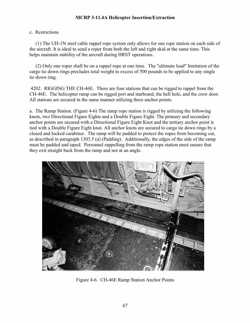
MCRP 3-11.4A Helicopter Insertion/Extraction
c. Restrictions (1) The UH-1N steel cable rappel rope system only allows for one rope station on each side of the aircraft. It is ideal to send a roper from both the left and right skid at the same time. This helps maintain stability of the aircraft during HRST operations. (2) Only one roper shall be on a rappel rope at one time. The "ultimate load" limitation of the cargo tie down rings precludes total weight in excess of 500 pounds to be applied to any single tie down ring. 4202. RIGGING THE CH-46E. There are four stations that can be rigged to rappel from the CH-46E. The helicopter ramp can be rigged port and starboard, the hell hole, and the crew door. All stations are secured in the same manner utilizing three anchor points. a. The Ramp Station. (Figure 4-6) The ramp rope station is rigged by utilizing the following knots, two Directional Figure Eights and a Double Figure Eight. The primary and secondary anchor points are secured with a Directional Figure Eight Knot and the tertiary anchor point is tied with a Double Figure Eight knot. All anchor knots are secured to cargo tie down rings by a closed and locked carabiner. The ramp will be padded to protect the ropes from becoming cut, as described in paragraph 1303.5 (a) (Padding). Additionally, the edges of the side of the ramp must be padded and taped. Personnel rappelling from the ramp rope station must ensure that they exit straight back from the ramp and not at an angle.
Figure 4-6. CH-46E Ramp Station Anchor Points
67
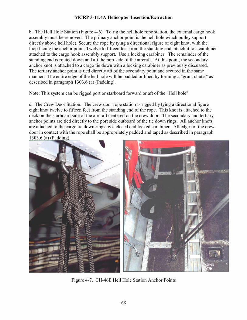
MCRP 3-11.4A Helicopter Insertion/Extraction
b. The Hell Hole Station (Figure 4-6). To rig the hell hole rope station, the external cargo hook assembly must be removed. The primary anchor point is the hell hole winch pulley support directly above hell hole). Secure the rope by tying a directional figure of eight knot, with the loop facing the anchor point. Twelve to fifteen feet from the standing end, attach it to a carabiner attached to the cargo hook assembly support. Use a locking carabiner. The remainder of the standing end is routed down and aft the port side of the aircraft. At this point, the secondary anchor knot is attached to a cargo tie down with a locking carabiner as previously discussed. The tertiary anchor point is tied directly aft of the secondary point and secured in the same manner. The entire edge of the hell hole will be padded or lined by forming a "grunt chute," as described in paragraph 1303.6 (a) (Padding). Note: This system can be rigged port or starboard forward or aft of the "Hell hole" c. The Crew Door Station. The crew door rope station is rigged by tying a directional figure eight knot twelve to fifteen feet from the standing end of the rope. This knot is attached to the deck on the starboard side of the aircraft centered on the crew door. The secondary and tertiary anchor points are tied directly to the port side outboard of the tie down rings. All anchor knots are attached to the cargo tie down rings by a closed and locked carabiner. All edges of the crew door in contact with the rope shall be appropriately padded and taped as described in paragraph 1303.6 (a) (Padding).
Figure 4-7. CH-46E Hell Hole Station Anchor Points
68

MCRP 3-11.4A Helicopter Insertion/Extraction
4203. RIGGING THE CH-53D/E. The ramp is rigged the same as the ramp of the CH-46E. The ramp will be padded to protect the rope from becoming cut as described in paragraph 1303.e (1) (Padding). Additionally, the edges of the side of the ramp must be padded and taped. Personnel rappelling from the ramp rope station must ensure that they exit straight back from the ramp and not at an angle. NOTE: The CH-53 helicopter is the least desired platform to rappel from due to the rotor wash.
69

MCRP 3-11.4A Helicopter Insertion/Extraction
CHAPTER 5
FAST ROPE OPERATIONS PARAGRAPH PAGE FAST ROPE PROCEDURES GENERAL 5100 72 OPERATIONAL CONSIDERATIONS 5101 72 AIRCRAFT RESTRICTIONS 5102 77 SEQUENCE OF EVENTS 5103 78 EMERGENCY PROCEDURES 5104 84 SECTION 2: AIRCRAFT RIGGING GENERAL 5200 82 RIGGING THE UH-1N 5201 82 RIGGING THE CH-46E 5202 84 RIGGING THE CH-53D/E 5203 87 FIGURES 5-1 FAST ROPING 72 5-2 FAST ROPE FAMILIARIZATION 73 5-3 LANDING WITH FAST ROPE ATTACHED 74 5-4 FAST ROPE TECHNIQUE 75 5-5 FAST ROPE SAFETY 76 5-6 DUAL GANTRY SYSTEM WITH CARGO RATCHET STRAP 77 5-7 FORWARD GANTRY POSITION 82 5-8 GANTRY FAST ROPE ATTACHMENT 84
70

MCRP 3-11.4A Helicopter Insertion/Extraction
5-9 SCHLOMER FRAME INSTALLED 85 5-10 SCHLOMER FRAME FAST ROPE ATTACHMENT 85 5-11 PRIMARY ANCHOR 86 5-12 SECONDARY ANCHOR 87 5-13 FAST ROPE ANCHOR BAR 87 5-14 QUICK RELEASE MECHANISM 87 5-15 A-FRAME FAST ROPE ATTACHMENT BAR 88 5-16 A-FRAME FAST ROPE ATTACHMENT BAR ATTACHED 88 5-17 CLEVES CONNECTOR WITH QUICK RELEASE PIN 89
71

MCRP 3-11.4A Helicopter Insertion/Extraction
CHAPTER 5
FAST ROPE OPERATIONS
SECTION 1: FAST ROPE PROCEDURES 5100. GENERAL. Fast roping is a technique utilized to rapidly introduce heliborne personnel into areas in which helicopters cannot land. Fast roping is a preferred method of insertion over rappelling due to its overall efficiency, effectiveness, and ease of installation. Fast roping does have a certain amount of risk, because the rope is attached to the roper only by hands and feet. With proper familiarization and training, Marines can quickly acquire the skill required to utilize fast ropes. Fast roping is a far less perishable skill than rappelling and requires less practice to remain proficient. The simplicity and speed of fast rope operations is its greatest attribute. Fast roping is dangerous with heavy loads (Figure 5-1).
Figure 5-1. Fast Roping 5101. OPERATIONAL CONSIDERATIONS a. Mission Aircraft. Fast roping can be conducted from the following USMC aircraft:
(1) UH-1N.
(2) CH-46E.
(3) CH-53D/E.
72

MCRP 3-11.4A Helicopter Insertion/Extraction
b. Familiarization. Thorough briefing is required for all users before fast rope operations are conducted. The brief should consist of, but not be restricted to, a review of all the equipment associated with fast rope, loading of personnel, helicopter approach, deplaning, descent, commands and signals, pre-flight, and in-flight safety procedures. For deplaning, it is essential that ropers receive the necessary training in fast rope technique before utilizing the fast rope on a tactical mission. When time and situation permit, it is encouraged to allow the unqualified ropers to watch a fast rope operation or take part in the equipment installation of the helicopter. This will build confidence in the equipment and fast rope techniques. All users new to fast rope will conduct slides for the first time without combat equipment until confidence and skill level warrant more difficult operations (Figure 5-2).
Figure 5-2. Fast Rope Familiarization c. Descent Authority. It is the sole responsibility of the HRST Master to order the descent of ropers. He is responsible for the precise placement of the fast rope on the target area. If safe conditions for descent are not met, the HRST Master shall cease fast rope operations. d. The crew chief will always position himself to observe the fast rope and will assist in directing the pilot in maintaining a stable hover over the target area. e. Rope Requirements.
73

MCRP 3-11.4A Helicopter Insertion/Extraction
(1) Rope deployment. Only the HAC can authorize the deployment of the rope. The
helicopter shall be in a stable hover prior to the "DEPLOY THE ROPE" command.
(2) Rope Retrieval:
(a) During non-tactical training evolutions, rope retrieval should be accomplished from a hover or after the helicopter has landed. This can be accomplished by one of two methods. The first is to manually release the rope(s) and air taxi clear to land. The second is to land from a hover with the rope(s) held laterally and clear of the rotors by the ropers on the ground (Figure 5-3).
Figure 5-3. Landing with Fast Rope Attached.
(b) Rope Release. When immediate retrieval is not required, the ropes can be manually
jettisoned from the hovering helicopter. f. Roper Responsibilities (1) Understand and comply with all aspects of HRST and emergency procedures. (2) Ensure all safety equipment is properly donned and inspected by a HRST Master (Figure 5-4).
(3) Ensure seat belts are hooked-up prior to take off and unbuckling only on command by the HRST Master.
(4) Maintain eye contact with the HRST Master at all times prior to beginning a descent. (5) Make deliberate movements toward the rope station while maintaining a hand hold in the aircraft at all times, and mounting the rope only on the HRST Master’s command.
74
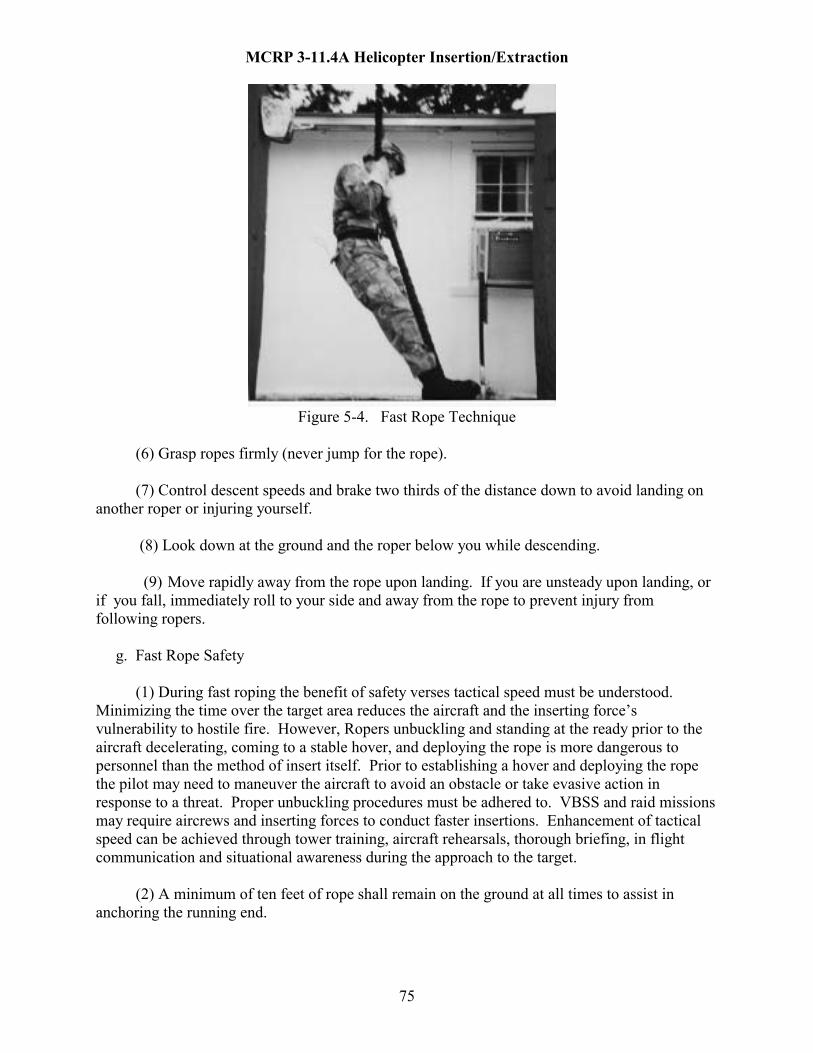
MCRP 3-11.4A Helicopter Insertion/Extraction
Figure 5-4. Fast Rope Technique (6) Grasp ropes firmly (never jump for the rope). (7) Control descent speeds and brake two thirds of the distance down to avoid landing on another roper or injuring yourself. (8) Look down at the ground and the roper below you while descending.
(9) Move rapidly away from the rope upon landing. If you are unsteady upon landing, or if you fall, immediately roll to your side and away from the rope to prevent injury from following ropers. g. Fast Rope Safety (1) During fast roping the benefit of safety verses tactical speed must be understood. Minimizing the time over the target area reduces the aircraft and the inserting force’s vulnerability to hostile fire. However, Ropers unbuckling and standing at the ready prior to the aircraft decelerating, coming to a stable hover, and deploying the rope is more dangerous to personnel than the method of insert itself. Prior to establishing a hover and deploying the rope the pilot may need to maneuver the aircraft to avoid an obstacle or take evasive action in response to a threat. Proper unbuckling procedures must be adhered to. VBSS and raid missions may require aircrews and inserting forces to conduct faster insertions. Enhancement of tactical speed can be achieved through tower training, aircraft rehearsals, thorough briefing, in flight communication and situational awareness during the approach to the target. (2) A minimum of ten feet of rope shall remain on the ground at all times to assist in anchoring the running end.
75

MCRP 3-11.4A Helicopter Insertion/Extraction
(3) Ropers will execute descents at speeds commensurate with their experience and proficiency in fast rope operations. (4) The HRST Master shall ensure a minimum of ten feet of interval between personnel on the fast rope (Figure 5-5).
Figure 5-5. Fast Rope Safety
(5) During descent, ropers must maintain visual contact with lower ropers and watch for obstructions. (6) Individual ropers will "LOCK IN" during emergencies by wrapping one leg one or two times around the rope and standing on the fast rope with the other foot. (7) During the actual descent, NVGs will not be used by ropers due to the limited depth perception and the tunnel vision effect.
(8) Upon reaching the ground, ropers should immediately run or roll out of the path of the next roper. (9) The first roper to the deck may remain at the base of the rope and assist in keeping the rope steady for other ropers. (10) Aircraft Drift. During the course of the descent, the aircraft may drift slightly causing the fast rope to hang at an angle vice vertical. If this occurs the HRST Master shall "HOLD" and have the crew chief direct the pilot over the target to restore a vertical rope position. (11) Each roper should be aware that as the proceeding roper departs the rope, a slight elastic reaction maybe detected in the rope.
76

MCRP 3-11.4A Helicopter Insertion/Extraction
(12) Altitude. The pilot shall hover at a minimum altitude to clear obstacles, but not so low that rotor downwash adversely affects the fast rope. Read Chapter 1, paragraph 1303 (Operational Safety). (13) All HRST members must be aware that as ropers depart the rope, the aircraft may have a tendency to climb slightly in altitude. (14) Anytime a fast rope is suspended from a helicopter, the HRST Master or crew chief must be prepared to quickly release the rope should it become entangled with an object outside the helicopter. AIRCRAFT RESTRICTIONS. The following restrictions are based on airframe, fast rope attach system, and rope limitations. It is mandatory that the restrictions outlined below be complied with in order to avoid injury to personnel and damage to aircraft. 5102. AIRCRAFT RESTRICTIONS a. UH-1N Restrictions (1) Only the gantry system configured with the original base plate assembly is authorized for attachment of the fast rope. (2) 600 Pound Limit. At no time shall the combined weight on the fast rope exceed 600 pounds. (3) When the two gantry system is used simultaneously it must have a cargo ratchet strap around the top of both the gantry posts as a back up safety (Figure 5-6).
77
MCRP 3-11.4A Helicopter Insertion/Extraction
Figure 5-6. Dual Gantry System With Cargo Ratchet Strap (4) Dual and single gantry systems are optional for all fast rope operations. Note that with the use of a single fueled auxiliary fuel cell, all fast roping must be conducted from the opposite side of the aircraft to ensure that the weight distribution does not exceed lateral limitations (i.e. one auxiliary fuel cell installed on left side with a dual or single gantry assembly mounted on the right side). (5) Although the gantry can be mounted at both forward and aft cabin stations, it is recommended that it be mounted at the forward stations port and starboard due to additional engineering restrictions placed on the aft station. (6) During fast rope operations, the UH-1N's angle of pitch and roll must not exceed plus or minus 10 degrees. b. CH-46E Restrictions (1) The Schlomer frame is capable of suspending two fast ropes simultaneously. However, due to the congested nature of the ramp area, utilizing two ropes at once is very difficult. Single rope operations from the Schlomer frame is recommended. Maximum capacity during single rope operations is two ropers on a rope.
(2) Fast rope operations utilizing the externally mounted rescue hoist and boom as a fast
rope attach point are prohibited. However, hell hole operations can be accomplished utilizing the fast rope interface kit. Maximum capacity during hell hole operations is one roper on the rope.
c. CH-53D/E Restrictions. (1) Due to the limitation of the quick release pin assembly associated with the CH-53 fast rope anchor bar, at no time shall the combined weight placed on the release assembly exceed 600 pounds.
(2) Fast rope operations utilizing the externally mounted rescue hoist and boom as a fast
rope attach point are prohibited. 5103. SEQUENCE OF EVENTS. a. CH-46E/CH-53D/E - Hell Hole/Ramp Fast Rope: NOTE: (HRST Master’s ICS calls are in bold print) (1) Load on signal from the crew chief and inspect the installation of the fast rope.
78

MCRP 3-11.4A Helicopter Insertion/Extraction
(2) Don your gunner’s belt and perform an ICS check. “ICS check”. Once the pilot responds, acknowledge his response by letting him know how you hear him. “I have you loud and clear” or “I have you the same” or “I have you weak”. (3) Once all roper’s are seated and strapped in, notify the crew chief that you are all set to begin. “Ropers are ready”. The crew chief will then clear the pilot for lift. (4) After take-off, the ropers shall remain strapped in, and the HRST Master shall remain oriented through periodic updates from the HAC. Once the HAC gives the “2-minutes” time warning, the HRST Master responds, “Roger, 2 minutes”. At this time the HRST Master will hold up two fingers and each roper will hold up two fingers on each gloved hand and repeat “2 minutes”. This gives the HRST Master a chance to verify that all roper’s have their helmets, eye protection, and gloves on and that they are awake and ready to go. (For hell hole operations, the crew chief will then assist the HRST Master by opening the hell hole door.) NOTE: AT NO TIME WILL THE HRST MASTER LEAVE AN OPEN ROPE STATION UNATTENDED. (5) The HAC will give the “1-minute” call, the HRST Master will respond. “Roger, 1 minute”. The HRST Master will then give the “1 minute” command to the ropers using hand and arm signals. Ropers should make final checks of all gear. (6) The HAC will give the command “Deploy rope”. Once the aircraft is in a stable hover and you can see the target directly below you, you may deploy the rope. (7) When the mission dictates and you have verified that the rope is unfouled, on the deck and on target, tell the HAC “Rope on the deck”. Give the following commands to the ropers, “Unbuckle”, “Take Position” using hand and arm signals. (8) Ensure you physically control the first roper to prevent him from losing his balance and falling out of the aircraft. Maintain this control until you tap him out and the roper begins his descent down the rope. (a) The HRST Master may be positioned on either side of the hell hole, beside the Schlomer frame or to the side of the CH-53D ramp. (b) Ensure the HRST Master and ropers know in advance what order they will be leaving the aircraft, to avoid confusion. Ropers can feed into the hell hole from either direction (forward or aft). (c) Subsequent ropers will continue to mount the rope. Physically control or feed each roper into the rope and tap each one out. Remember to keep a of 10 foot minimum interval between ropers.
79

MCRP 3-11.4A Helicopter Insertion/Extraction
(d) Once the last man is on the ground, inform the pilot “Last man on deck”. This will be followed by “Rope being pulled to # clock position” or “Rope is jettisoned” or “Rope is in”. Whichever is appropriate from the brief given. HRST MASTER HAC ROPERS Load on command Sit down and buckle in Inspect rigging & Don gunner’s belt “ICS check” Acknowledge
ICS check
“I have you loud and clear” “Ropers are ready” “2 minutes” “Roger, 2 minutes” To ropers, “2 minutes”, & hand/arm signal
Repeat “2 minutes” & hand/arm signal
Visually inspect helmets/goggles/gloves “1 minute” “Roger, 1 minute” To ropers, “1 minute”, & hand/arm signal
Repeat “1 minute” & hand/arm signal, make final checks of all gear
“Deploy rope” “Roger, deploy rope”, Deploy rope, inspect if unfouled
“Rope is on the deck” To ropers, “Unbuckle”,” Take position”
Get into position as directed
Tap out ropers “Last man on deck” “Rope is at the # clock position”/”Rope jettisoned”/Rope is in”
b. UH-1N Fast Rope: sequence of events is the same as the CH-46E/CH-53D/E. (1) All steps are identical to those in the CH-46E/CH-53D/E; except you will be straddling the gantry frame and your ropers will be sitting in the briefed positions. (2) Ensure you physically control the ropers and prevent them from falling out of the aircraft once their lap belt has been removed. Maintain this control until the roper begins his descent down the rope.
80

MCRP 3-11.4A Helicopter Insertion/Extraction
5104. EMERGENCY PROCEDURES a. Aircraft Emergency. If the helicopter experiences engine failure or any aircraft emergency during fast rope, the Marines on the rope will descend as rapidly as possible and move from beneath the helicopter to the six o'clock position.
(1) The HRST Master shall "ABORT" (cease fast rope operations).
(2) The HRST Master shall ensure ropers already descending remain clear of the rope and possible helicopter impact area.
(3) The HRST Master shall direct ropers inside the aircraft to remain clear of openings, take their seats and re-buckle seat belts.
(4) All personnel shall then follow the crew chief's directions.
(5) 'HOLD" -- Stand fast and await further instructions.
(6) "STRAP IN” -- The HRST Master or crew chief may direct ropers remaining in the aircraft to don seat belts/safety straps and prepare for an unplanned landing.
81

MCRP 3-11.4A Helicopter Insertion/Extraction
CHAPTER 5
FAST ROPE OPERATIONS
SECTION 2: AIRCRAFT RIGGING 5200. GENERAL. All USMC helicopters must utilize an approved system for attaching the fast rope. All attaching systems shall incorporate a fail-safe rope quick release device when ever possible. Due to the loads placed on attach points during fast rope operations, careful inspection of aircraft rigging is mandatory by the HRST Master and the HAC to preclude injury to ropers and damage to the aircraft. 5201. RIGGING THE UH-1N a. The simplistic design and light weight structural composition of the gantry and base plate assembly allow for easy installation and removal to include installation of safety belts on the cabin floor and safety straps on the overhead. The installation time varies from approximately ten to fifteen minutes per gantry depending upon the experience level of the crew member (s). b. Gantry operations from the forward positions require the forward wing doors be removed (Figure 5-7).
Figure 5-7. Forward Gantry Position
82
MCRP 3-11.4A Helicopter Insertion/Extraction
c. The UH-1N gantry assembly is a derivative of the standard Bell Helicopter Textron, Combat Search and Rescue Hoist (COMSARH) assembly mounted on a fixed boom, minus the control box, winch cable, and arm end pulley. The boom is attached to a vertical post, which can be secured to existing cabin floor and overhead mounting points. The base and top of the post assembly can be located at four fuselage positions. The structure has been engineered to withstand accelerated gravity (G) forces up to an established ultimate loading limit set well above the maximum applied loading limitations. d. The original gantry assembly designed by Bell Helicopter includes a base plate assembly that attaches to the post with an extended link arm. This base plate assembly must be secured to the cabin floor by two mounting studs (hard points) that share the fore and aft forces applied through the link arm. The base plate assembly requires both adapters to be repositioned and aligned to the appropriate mounting studs for gantry relocation. The top of the assembly must be locknut tightened by hand since excessive force may result in damage to the cabin overhead. These attach points must be double checked for security to ensure personnel safety. e. The gantry assembly is not interchangeable from the right to left mounting positions due to the attachment of the link arm assembly. Hence, there is a right and a left type gantry assembly and these should be properly marked and in place. There will be a safety cargo strap wrapped around and connecting the two together as a secondary anchor for both. f. On some assemblies, there are two tabs mounted in the top portion of the boom assembly that are used in conjunction with cable guides on previous hoist assemblies. These tabs serve no purpose for the gantry system and tend to snag the safety cable when the rope is jettisoned from the boom assembly while in a hover. This is a potential hazard to aircrew men and should be removed on all existing gantry assemblies. g. The gantry assembly can be locked in two positions; inboard for stowage and extended outboard for operational use. The post can be manually rotated by unpinning the link arm to allow for repositioning of the boom assembly. h. The boom has a quick disconnect pin designed for the attachment of the fast rope and safety cable (Figure 5-8). i. The fast rope is attached to the gantry through the bottom orifice of the gantry arm with a quick disconnect pin. The safety cable runs freely over the top of the arm and is secured with a second quick disconnect pin. WARNING: DO NOT ROUTE THE SAFETY CABLE THROUGH THE GANTRY ARM. THIS MAY HAMPER CUT ROPE PROCEDURES.
83

MCRP 3-11.4A Helicopter Insertion/Extraction
Figure 5-8. Gantry Fast Rope Attachment 5202. RIGGING THE CH-46E a. Schlomer frame. (1) The Schlomer frame is designed to fit on the outside of the conveyer roller guides on the deck of the cargo ramp. It attaches to the helicopter at two forward and two aft mount points (Figure 5-9). Each forward mount point consists of a bracket assembly which affixes to two floor tie down rings with 3/4" quick release pins. The aft mount points consist of two "piano- hinged" steel plated which slide into the same mount channels used for the vehicle loading extension panels. These panels must be removed in order to install the fast rope frame. The rope is attached to the frame at a "U" - section cross bar with a 3/4" quick release pin (Figure 5-10). The frame design enables the helicopter to fly with its ramp and hatch closed and the folded frame mounted and secured in place. When directed, the crew chief will raise the hatch and lower the ramp to the level position. With the aid of the HRST Master, the crew chief unfolds the frame and locks the cross bar into place.
84

MCRP 3-11.4A Helicopter Insertion/Extraction
Figure 5-9. Schlomer Frame Installed
Figure 5-10. Schlomer Frame Fast Rope Attachment (2) After unfolding the frame for deployment, two 3/8" steel pins must be inserted into holes to lock the cross bar into place. In daylight, this operation is quite simple and can be accomplished quickly. At night, this pin alignment/insertion can be difficult and may require more time to insert.
85

MCRP 3-11.4A Helicopter Insertion/Extraction
(3) While it is possible for one crew member to install the frame on the deck, the frame's weight and bulkiness are better manipulated with more people. (4) The ramp/hatch configuration, and unfolding and deployment sequence of the frame and rope can be accomplished by a single person. However, the deployment of the frame and fast rope is more efficiently accomplished by the crew chief and HRST Master working together. (5) Frame installation time averages between 5 and 8 minutes utilizing 3 or 4 maintenance personnel. Two people can easily install the frame in less than 10 minutes. b. Hell hole. (1) When rigging the CH-46E hell hole station for fast rope operations, the CH-46E Interface Kit is used. This system incorporates two steel double clevices, two quick release pins, two steel locking carabiners, and a cargo sling. (2) Attach one double clevice to the rescue pulley attachment point with a carabiner and lock the gate. (3) Connect the fast rope to the double clevice utilizing the quick release pin. This is the primary anchor (Figure 5-11).
Figure 5-11. Primary Anchor
(4) Attach the safety cable to the second double clevice utilizing a quick release pin. Pass the free end of the cargo sling through the cargo tie downs, up behind the lower rail, up over the upperrail. Pass the sling around the rail support and back down. Insert into slide bar and take out slack with slide bar adjuster. Attach the double clevice to the cargo sling loop with the carabiner and lock the gate. Tie a knot in the free end of the cargo sling to prevent slippage (Figure 5-12).
86

MCRP 3-11.4A Helicopter Insertion/Extraction
Figure 5-12. Secondary Anchor 5203. RIGGING THE CH-53D a. The CH-53D fast rope anchor bar secures to two permanently installed brackets mounted on each cabin bulkhead at fuselage station (F. S.) 631.5 just aft of the ramp. The anchor bar can be easily removed when not in use (Figure 5-13).
Figure 5-13. Fast Rope Anchor Bar b. Two release assemblies are mounted on the anchor bar fifteen inches from each end. Each is compromised of a quick release mechanism that provides an anchor point for the fast rope (Figure 5-14).
Figure 5-14. Quick Release Mechanism
87

MCRP 3-11.4A Helicopter Insertion/Extraction
c. The overhead ramp door must be removed prior to installation of the anchor bar. The total installation time is 40 minutes (25 minutes for the overhead ramp door and 15 minutes for the bar assembly and related support equipment). An experienced crewmember may take less time. A minimum of two crewmembers are required for both installation and removal of the overhead ramp door. d. Overhead hand holds should be installed. This can easily be accomplished utilizing cargo straps. e. The CH-53E A-Frame Fast Rope Attachment Bar is manufactured by the MALS and maintained by the squadron. The bar is installed by the aircrew in approximately 1/2 hour. The bar consists of: (1) 21" stainless steel round stock, 1" in diameter, and threaded on each end, (2) 6 1/2" mono sleeves, (1) 2 1/4" mono sleeves, (2) stainless steel peanut-link brackets, and (1) 1" Q/D pin) (Figure 5-15) When installed, the bar replaces the two bolts used to attach the A-frame. However, the A-frame may also be completely removed.
Figure 5-15. A-Frame Fast Rope Attachment Bar f. Prior to use, the HRST Master must inspect to see if the bar is properly installed. Ensure the nuts are present on each end of the bar and is secured in place. g. To attach the rope, secure the 3" ring of the fast rope to the 1" quick release pin of the A-frame fast rope attachment bar assembly (Figure 5-16). Attach a double clevis assembly to either hard point directly aft of the primary attachment point. Connect the safety cable of the fast rope to the quick release pin of the double clevis assembly (Figure 5-17).
Figure 5-16. A-Frame Fast Rope Attachment Bar Attached
88

MCRP 3-11.4A Helicopter Insertion/Extraction
Figure 5-17. Cleves Connector with Quick Release Pin h. To jettison the rope, remove the quick release pin on the safety cable first and then release the 1" quick release pin on the A-frame attachment bar.
89

MCRP 3-11.4A Helicopter Insertion/Extraction
CHAPTER 6
SPECIAL PATROL INSERTION/EXTRACTION (SPIE) OPERATIONS PARAGRAPH PAGE SECTION 1: SPIE PROCEDURES GENERAL 6100 92 OPERATIONAL CONSIDERATIONS 6101 92 SPIE FAMILIARIZATION 6102 96 TACTICAL LAND EXTRACTION 6103 98 WATER EXTRACTION 6104 99 ROPER’S RESPONSIBILITIES AND PROCEDURES 6105 99 SEQUENCE OF EVENTS 6106 101 SECTION 2: AIRCRAFT RIGGING GENERAL 6200 106 RIGGING THE UH-1N 6201 106 RIGGING THE CH-46E 6202 108 FIGURES 6-1 SPIE OPERATIONS 92 6-2 DONNING OF SPIE HARNESS 92 6-3 DONNING OF THE NEW LIGHT WEIGHT SPIE HARNESS 92 6-4 FRICTION ADAPTER 94 6-5 LEG STRAP 94 6-6 SAFETY LINE 95
90

MCRP 3-11.4A Helicopter Insertion/Extraction
6-7 SPIE EXTRACTION 97 6-8 PRIMARY INSTALLATION 106 6-9 ALTERNATE INSTALLATION 107 6-10 SLINGS SECURED BY CARABINERS 108 6-11 CH-46E SPIE ROPE INSTALLATION 108
91

MCRP 3-11.4A Helicopter Insertion/Extraction
CHAPTER 6
SPECIAL PATROL INSERTION/EXTRACTION (SPIE) OPERATIONS
SECTION 1: SPIE PROCEDURES 6100. GENERAL. The Special Patrol Insertion/Extraction (SPIE) system was developed as a means to rapidly insert and/or extract a reconnaissance patrol from an area that does not permit a helicopter to land (Figure 6-1). SPIE has application for rough terrain as well as water inserts/extracts. Generally, the SPIE rope is lowered into the pickup area from a hovering helicopter. Patrol personnel, each wearing a harness with an attached carabiner, hook up to a D-ring inserted in the SPIE rope. A second safety line is attached to a second D-ring located above the first. The helicopter lifts vertically from an extract zone until the rope and personnel are clear of obstructions, then proceeds in forward flight to a secure insert zone. The rope and personnel are treated as an external load and airspeeds, altitudes, and oscillations must be monitored.
Figure 6-1. SPIE Operations 6101. OPERATIONAL CONSIDERATIONS a. Mission Aircraft. SPIE can be conducted from the following USMC aircraft:
92
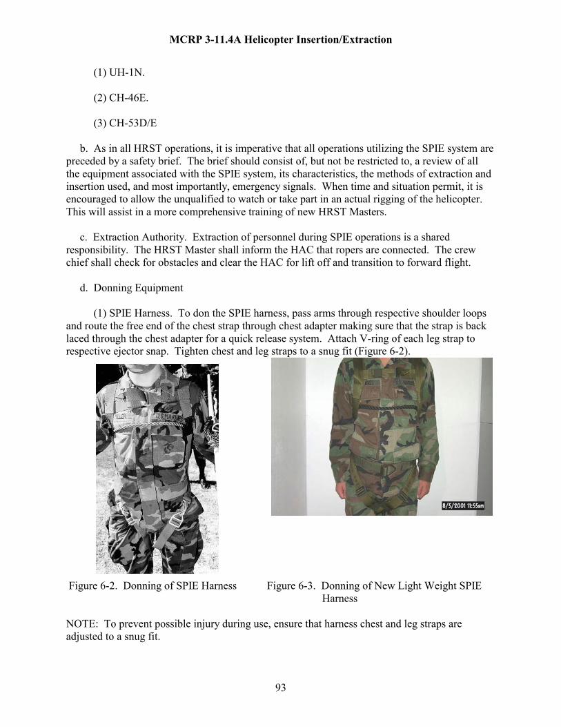
MCRP 3-11.4A Helicopter Insertion/Extraction
(1) UH-1N. (2) CH-46E. (3) CH-53D/E b. As in all HRST operations, it is imperative that all operations utilizing the SPIE system are preceded by a safety brief. The brief should consist of, but not be restricted to, a review of all the equipment associated with the SPIE system, its characteristics, the methods of extraction and insertion used, and most importantly, emergency signals. When time and situation permit, it is encouraged to allow the unqualified to watch or take part in an actual rigging of the helicopter. This will assist in a more comprehensive training of new HRST Masters. c. Extraction Authority. Extraction of personnel during SPIE operations is a shared responsibility. The HRST Master shall inform the HAC that ropers are connected. The crew chief shall check for obstacles and clear the HAC for lift off and transition to forward flight. d. Donning Equipment (1) SPIE Harness. To don the SPIE harness, pass arms through respective shoulder loops and route the free end of the chest strap through chest adapter making sure that the strap is back laced through the chest adapter for a quick release system. Attach V-ring of each leg strap to respective ejector snap. Tighten chest and leg straps to a snug fit (Figure 6-2).
Figure 6-2. Donning of SPIE Harness Figure 6-3. Donning of New Light Weight SPIE Harness NOTE: To prevent possible injury during use, ensure that harness chest and leg straps are adjusted to a snug fit.
93

MCRP 3-11.4A Helicopter Insertion/Extraction
(2) New Light Weight SPIE Harness (Figure 6-3). To don the SPIE harness, pass arms through the respective shoulder loops ensuring the chest adaptor is to the wearers left. Route the free end of the chest strap through the chest adaptor making sure the strap is back laced through the chest adaptor for a quick release system. In accordance with Figure 6-4 make sure the oversized portion of the leg strap friction adaptors are down against the body and route the led straps through the leg strap friction adaptors in accordance with Figure 6-5, tighten leg straps to fit and stow excess in the leg strap retainers. Figure 6-4. Friction Adapter Figure 6-5. Leg Strap
94

MCRP 3-11.4A Helicopter Insertion/Extraction
(3) Safety Line. A safety line for normal attachment of the carabiner on the D-ring consists of the 12 to 15 foot sling rope and an additional carabiner. The rope is secured around the roper's chest with the bowline knot. The roper then takes the running end of the sling rope and extends it to arms length. A double figure "8" loop is made and a carabiner is then connected to the upper or lower D-ring of the SPIE rope. Do not attach carabiner to the same D-ring as the harness. The backup attachment is intended for use in training exercises, and will be worn under the SPIE harness (Figure 6-6).
Figure 6-6. Safety Line e. SPIE Safety (1) During Extraction. The HRST Master will maintain a positive means of communication with the pilot at all times to ensure proper positioning of the aircraft for extraction. The HRST Master will hold the aircraft's ascent until the team leader gives an "ALL READY" (thumbs up) signal advising the HRST Master that all extraction personnel are safely attached. (2) During Flight. The HRST Master will watch the SPIE rope and attached personnel during flight to ensure proper altitude is maintained and that the rigging remains safely attached. (3) During Landing. The HRST Master must relay lowering instructions to the pilot to prevent contact with obstacles on the landing zone. In addition, he will ensure that all team members are completely clear of the rope before giving the signal for the pilot to takeoff. (4) Communications. Due to the distance between the ropers tethered on the SPIE rope, the HRST Master located inside the aircraft, and the noise associated with the helicopter, voice
95

MCRP 3-11.4A Helicopter Insertion/Extraction
communications are impossible. During the pre-flight Brief to HRST Members, hand-and-arm signals between ropers and the HRST Master must be covered in detail and clearly understood by all HRST members. (5) Airspeed. Airspeed shall not exceed 70 knots in warm weather operations or 50 knots during cold weather operations. (6) Altitude. A minimum altitude of 250 feet from the last man on the line to the highest obstacle on the deck must be maintained for SPIE operations during forward flight. The aircrew shall make use of the aircraft's Radar Altimeter for reference in maintaining a safe altitude for ropers. Make specific note of the Radar Altimeter's reading when last roper is lifted off of the ground. This reading is utilized to determine obstacle clearance and will assist in insert of ropers into next zone. The roper should not descend at a rate faster than 300 fpm. (7) Hell Hole. During CH-46E and CH-53D/E SPIE operations, the hell hole hatch will remain open. Care must be taken to avoid an accidental fall through while working around the hellhole. 6102. SPIE FAMILIARIZATION a. Static training (in a pool for wet SPIE) is not required for SPIE operations, however, all personnel should participate in familiarization training prior to conducting SPIE operations. Familiarization should consist of, but not be limited to; SPIE safety, procedures to don individual equipment, mounting procedures, in-flight procedures, emergency procedures and dismounting procedures. b. All individuals training in SPIE for the first time will conduct extracts without combat equipment. This will assist in building the roper's confidence level. c. Prior to mounting, assignments are made as to which position you will mount on the rope. Ropers may be positioned as singles, pairs or any combination, providing the bottom point on the rope is always filled. Load the line starting from the bottom positions to the top. d. Single Mounting: Place your safety line and main lift web over the shoulder closest to the rope, then approach the rope on the proper side from the running end of the rope. Attach the carabiner of your main lift web to the D-ring furthest from the aircraft and secure the gate. Attach your safety line carabiner to the D-ring on the opposite side of the rope, to the upper D-ring and secure the gate. Place the main lift web, safety rope and SPIE rope over the top of your inboard shoulder and give the “Thumbs Up” with your outboard hand signifying you are ready to lift (Figure 6-4). e. Pair Mounting: Each roper will place their safety line and main lift web over the shoulder closest to the rope. Each roper attaches his main lift web carabiner to the D-ring on his side of the rope, and his safety carabiner to his partner’s primary attachment D-ring. Ensure all carabiners art attached to a D-ring, not another carabiner. Once attached, secure the gates.
96

MCRP 3-11.4A Helicopter Insertion/Extraction
Partners will hold each other around the waist, ensuring all ropes and main lift webs pass over the top of the shoulder, and give the “Thumbs up” signifying they are ready to lift. (1) As the aircraft begins to ascend, begin walking toward the aircraft. The idea is to be located directly under the aircraft when all slack is removed from the rope. As you start to lift, let go of the SPIE rope but maintain “Thumbs up” throughout the initial ascent until everyone is airborne, and the aircraft transitions to forward flight. (2) Once suspended from the rope, keep your arms extended to reduce the spinning. Do not adjust your harness in any way. Should your helmet feel like it is coming loose, grasp it by the chinstrap to hold it in place. (3) Any roper may declare an emergency at any time. One relatively common emergency is when a roper finds himself entangled under the safety line or primary lift web during the initial lift. The roper, his SPIE partner or any other member may give the emergency signal. When one roper gives the signal, all ropers will give the signal until the situation is corrected. During daylight operations, daylight operations, both hands are placed on top of the helmet. During night operations, each roper should have a chem light or other visual signal. (4) Once on the ground, immediately begin walking in the direction stated during the ropers brief. Be cautious not to drag fallen ropers, or pull the rope so tight that it binds on the edge of the aircraft. Keep walking away from the aircraft until all ropers are on the ground. (5) During training, if the helicopter is going to land, do not disconnect your primary and secondary anchor devices until the helicopter is sitting on the deck to avoid getting your fingers injured in a carabiner. During tactical evolutions and the helicopter is not going to land, begin disconnecting your primary and secondary anchor devices only after your feet touch the ground.
Figure 6-4. SPIE Extraction
f. Dismounting Procedures. Upon reaching the ground, all ropers should immediately head in the direction of the aircraft's 3, 9, or 12 o'clock position. If the helicopter is making a
97

MCRP 3-11.4A Helicopter Insertion/Extraction
scheduled landing at this time, it will be up to the team to ensure that the rope is pulled taut to the 3, 9, or 12 o'clock position as the helicopter descends vertically to land. 6103. TACTICAL LAND EXTRACTION. The SPIE system should be used only in those cases where the patrol requires immediate extraction and/or is unable to move to a clear area suitable for helicopter landing (figure 6-4). a. The extraction helicopter proceeds to the area and radio/visual contact with the patrol is established. Once the patrol has indicated ready for pickup, and the tactical situation has stabilized, the helicopter moves to the pickup area by a route that affords maximum safety to the aircraft. Once above the team’s location, the HRST Master deploys the SPIE rope on order from the HAC. b. The team should use the same procedure devised in paragraph 6102 of this chapter for its hook up. Once the team is hooked up using both their primary (harness) hook up point and their secondary (safety line) hook up point, they should turn so they are facing the direction the rope is headed, and pass a "thumbs up" to the team leader. The main difference between this evolution and the familiarization phase is the carrying and securing of individual weapons. When all members are ready, the team leader signals a "thumbs up" (daytime) to the HRST Master. At night, a prearranged signal of lights will be used. Patrol members move forward (toward the helicopter) as the patrol is being lifted. c. During the extraction, the team radio operator should maintain his communications with the extraction helicopter in order to give a verbal backup to the "thumbs up" signal and also to relay any other information during the flight. The radio operator's position should be near or at the bottom hook up point to assist in giving accurate information concerning the extract, the clearing of obstacles, and the descent. d. Lift off by the extraction aircraft must be vertical until the SPIE rope has cleared all obstacles. Patrol members can fire their individual weapons using the hip position and with their barrel directed downward at a 45 degree angle and outward. Weapons and equipment should be properly line attached to prevent their loss during SPIE operations. e. Once the SPIE rope has cleared all obstacles, the extraction aircraft transitions to horizontal flight and departs the area by the safest route. Airspeed should be limited to 70 knots in warm weather or 50 knots in cold climate while team members are attached to the SPIE rope. f. When the extraction aircraft has reached a safe dismount area, a transition is made to a hover 250 feet above the highest obstacle from the last man. Once the aircraft is clear of all obstacles a vertical descent is commenced. The aircrew and HRST Master will provide continuous altitude and clearance information to the pilot. Vertical descent rate of the aircraft should be no greater than 300 fpm. Descent rates greater than 300 fpm increase the risk of injury to ropers. Caution: higher hovers at higher altitudes are more difficult due to lack of references. This can result in excessive descent rates.
98

MCRP 3-11.4A Helicopter Insertion/Extraction
g. As in the familiarization phase of training, when reaching the ground the team will immediately move out from under the man or men above them and move toward the designated 3, 9, or 12 o'clock position of the aircraft. All team members should rapidly unhook themselves and render assistance to others. Once this is accomplished they will either move away from the area and set up security or will assist in clearing the rope if the helicopter is going to land. 6104. WATER EXTRACTION. The SPIE system is also suitable for extraction of reconnaissance swimmers from the water. For this procedure, three inflatable life vests or flotation devices will be tied to SPIE rope to provide buoyancy for the rope while in the water. Tie one flotation device at each end of the attachment points and one flotation device at each end of the attachment point area, just above the middle two sets of D-rings. The reconnaissance swimmers to be extracted should wear the SPIE harness under their individual life vest. They may also wear swimming fins, mask, and snorkel (amphibious operations) to facilitate hooking up to the SPIE rope within the spray area beneath the hovering helicopter. a. After the extraction helicopter has attained a stable hover 50-70 meters away from the reconnaissance swimmer's location, the HRST Master will drop the SPIE line (flotation attached) on order from the pilot. The pilot will then drag the line to the swimmers. b. When the team members have completed hook up to the SPIE rope, the team leader will signal the HRST Master with a "thumbs up" to commence lift off. c. Lift off of the extraction aircraft must be vertical until all team members and the bottom end of the rope has cleared the water. During this initial lift off, it is important for the individuals to realize that they may be dragged through the water and be prepared to roll on their backs until they are clear of the water. d. Flight speed and altitude should be the same as overland. The dismounting procedure will also remain the same except when landing on a ship. From the moment team members step on the deck, all members must take their orders from the deck personnel in charge of the landing platform. e. It is important for the pilots to have visual reference points to ensure that the aircraft remains in vertical hover. By pointing the nose of the aircraft toward land, when possible, the pilots will have a reference point to assist in a vertical hover. Lack of a visual reference point will cause the aircraft to drift, making swimmer hook up with SPIE rope attachment rings very difficult and often hazardous. 6105. ROPER’S RESPONSIBILITIES AND PROCEDURES a. Training and safety equipment can only decrease, not eliminate, the inherent dangers of SPIE operations. Likewise, HRST Masters and SIOs can neither foresee nor prevent every mishap. Whether mounting, extracting, transiting, descending, or dismounting, or weathering an aircraft emergency, SPIE safety depends largely upon the technical expertise and prudent judgment of the individual SPIE roper. Ropers are responsible for the following:
99

MCRP 3-11.4A Helicopter Insertion/Extraction
(1) Understand and comply with all aspects of HRST and emergency procedures. (2) Ensure all safety equipment is properly donned and inspected by a HRST Master. (3) Properly don and inspect the safety line and SPIE harness, ensuring a snug fit. (4) As the uppermost roper, maintain eye contact with the HRST Master during extraction, flight, and descent. (5) Repeat all commands relayed by the top roper from the HRST Master. (6) Mount the rope only after it has contacted the ground. (7) Maintain eye contact with the ground while descending. (8) Move out from under higher ropers immediately upon contacting the ground. (9) Move to the 3-o’clock or 9-o’clock position once on the ground. (10) During training, if the helicopter is going to land, do not disconnect your primary and secondary anchor devices until the helicopter is sitting on the deck to avoid getting your fingers injured in a carabiner. During tactical evolutions and the helicopter is not going to land, begin disconnecting your primary and secondary anchor devices only after your feet touch the ground. (11) Remain prepared to disconnect any injured or unconscious ropers. (12) Move rapidly away from the SPIE rope upon dismounting. b. Individual Roper Procedures: Static training (in a pool for wet SPIE) is not required for SPIE operations, however, all personnel should participate in familiarization training prior to conducting SPIE operations. Familiarization should consist of, but not be limited to; SPIE safety, procedures to don individual equipment, mounting procedures, in-flight procedures, emergency procedures and dismounting procedures. Prior to mounting, assignments are made as to which position you will mount on the rope. Ropers may be positioned as singles, pairs or any combination, providing the bottom point on the rope is always filled. Load the line starting from the bottom positions to the top. (1) Single Mounting: Place your safety line and main lift web over the shoulder closest to the rope, then approach the rope on the proper side from the running end of the rope. Attach the carabiner of your main lift web to the D-ring furthest from the aircraft and secure the gate. Attach your safety line carabiner to the D-ring on the opposite side of the rope, to the upper D-ring and secure the gate. Place the main lift web, safety rope and SPIE rope over the top of your inboard shoulder and give the “Thumbs Up” with your outboard hand signifying you are ready to lift.
100

MCRP 3-11.4A Helicopter Insertion/Extraction
(2) Pair Mounting: Each roper will place their safety line and main lift web over the shoulder closest to the rope. Each roper attaches his main lift web carabiner to the D-ring on his side of the rope, and his safety carabiner to his partner’s primary attachment D-ring. Ensure all carabiners art attached to a D-ring, not another carabiner. Once attached, secure the gates. Partners will hold each other around the waist, ensuring all ropes and main lift webs pass over the top of the shoulder, and give the “Thumbs up” signifying they are ready to lift. (3) As the aircraft begins to ascend, begin walking toward the aircraft. The idea is to be located directly under the aircraft when all slack is removed from the rope. As you start to lift, let go of the SPIE rope but maintain “Thumbs up” throughout the initial ascent until everyone is airborne, and the aircraft transitions to forward flight. (4) Once suspended from the rope, keep your arms extended to reduce the spinning. Do not adjust your harness in any way. Should your helmet feel like it is coming loose, grasp it by the chinstrap to hold it in place. (5) Any roper may declare an emergency at any time. One relatively common emergency is when a roper finds himself entangled under the safety line or primary lift web during the initial lift. The roper, his SPIE partner or any other member may give the emergency signal. When one roper gives the signal, all ropers will give the signal until the situation is corrected. During daylight operations, daylight operations, both hands are placed on top of the helmet. During night operations, each roper should have a chem light or other visual signal. (6) Once on the ground, immediately begin walking in the direction stated during the ropers brief. Be cautious not to drag fallen ropers, or pull the rope so tight that it binds on the edge of the aircraft. Keep walking away from the aircraft until all ropers are on the ground. (7) During training, if the helicopter is going to land, do not disconnect your primary and secondary anchor devices until the helicopter is sitting on the deck to avoid getting your fingers injured in a carabiner. During tactical evolutions and the helicopter is not going to land, begin disconnecting your primary and secondary anchor devices only after your feet touch the ground. 6106. SEQUENCE OF EVENTS a. CH-46E - SPIE (Administrative): NOTE: (HRST Master’s ICS calls are in bold print) (1) Load on signal from the crew chief and inspect the installation of the SPIE rope. (2) Don your gunner’s belt and perform an ICS check. “ICS check”. Once the pilot responds, acknowledge his response by letting him know how you hear him. “I have you loud and clear” or “I have you the same” or “I have you weak”. (3) Once all roper’s are connected to the SPIE rope, notify the crew chief that you are all set to begin. “Ropers are ready”. The crew chief will then clear the pilot for lift.
101
MCRP 3-11.4A Helicopter Insertion/Extraction
(4) As the aircraft begins to lift, lay down on your stomach on the forward side of the hell hole with your feet towards the cockpit and monitor the ropers for anything out of the ordinary and the SIO for a “Hold” signal. Ensure the pilot lifts straight up correcting any drift immediately. (5) At approximately 85’ AGL, the top roper(s) will become airborne. Tell the HAC, “First man off the deck”. (6) At approximately 120’ AGL, the bottom roper(s) will become airborne. Again, notify the pilot by saying “Last man off the deck”. (7) The pilot will continue to ascend straight up, calling out his altitude. Once you hear an altitude of 250’ AGL or higher, you will then say, “Request forward flight”. At this time the crew chief will ensure that the aircraft and ropers are clear of all obstacles and clear the pilot for forward flight. (8) Throughout the flight, monitor the ropers for the emergency signal. If all is well, inform the pilot by simply saying, “Ropers look good”. If there is a problem on the rope, you need to let pilot know. This is done by simply saying in a firm but unexcited voice, “Sir, we have a problem on the rope. We need to put the ropers down immediately”. The pilot will then proceed to the nearest or pre-briefed landing zone. (9) As the aircraft comes over the zone, the crew chief will talk the pilot into a steady hover at a minimum altitude of 250’ AGL. Once stabilized, the pilot will begin descent. (10) The crew chief will advise the HAC of the lowest ropers distance above the ground. (11) When the bottom roper reaches the deck, tell the HAC “First man on deck”. (12) When the top roper reaches the deck, tell the HAC “Last man on deck”. (13) As each roper reaches the deck they should move in a pre-briefed direction (3 or 9 o’clock). Once the last man reaches the deck and you tell the HAC, you need to notify him which direction the ropers are moving. Tell the HAC, “Ropers moving to your # o’clock”. The crew chief will then take over and clear the pilot to land. NOTE: Ensure the pilot does not land on the SPIE rope, as this will damage the rope. Sequence of events: HRST MASTER HAC ROPERS Load on command Hooking up & being inspected by
SIO Inspect rigging & Don gunner’s belt
102

MCRP 3-11.4A Helicopter Insertion/Extraction
“ICS check” Acknowledge ICS check
“I have you loud and clear” Thumbs up “Ropers are ready” “First man off the deck” First roper off the deck “Last man off the deck Last roper off the deck “Request forward flight” “Ropers look good” “First man on deck” First roper on the deck “Last man on deck” Last roper on the deck “Rope moving to your # o’clock”
b. UH-1N - SPIE (Administrative): All steps for an administrative SPIE extract are identical as those for the CH-46E administrative SPIE Extract except for the following: (1) The HRST Master’s position is lying across the aircraft cabin with his head on the same side as the chopping block. (2) The ropers will pull the rope out to the 12 o’clock, once they have reached the deck. NOTE: Be aware of the wire cutter mounted on the aircraft below the pilots as this could damage the rope should it come in contact with it. c. CH-46E – SPIE (Tactical): NOTE: (HRST Master’s ICS calls are in bold print) (1) Load on signal from the crew chief and install/inspect the installation of the SPIE rope. (2) Don your gunner’s belt and perform an ICS check. “ICS check”. Once the pilot responds, acknowledge his response by letting him know how you hear him. “I have you loud and clear” or “I have you the same” or “I have you weak”. (3) Once you are ready, let the crew chief know by saying “HRST Master all set”. The crew chief will then clear the pilot for lift. (4) As you are flying to the extract zone, the pilot should give you time warnings as briefed, ensuring that he gives you the “1-minute” warning as a minimum. At the “1-minute” warning, respond by saying “Roger, 1-minute”. Take position on the forward side of the hell hole. (5) Once the aircraft is over the extract LZ, the HAC will command, “Clear to deploy rope”. Respond, “Roger, deploy rope”. Once you see the LZ directly below you, you may deploy the SPIE rope through the hell hole. Once the rope is deployed and is on the deck notify the pilot by saying “Rope is on the deck”. NOTE: Ensure the rope is deployed through the proper opening of the Type-26 cargo slings so as not to create a twist in the installation.
103
MCRP 3-11.4A Helicopter Insertion/Extraction
(6) The extract team will then begin to hook up. Tell the HAC “Ropers hooking up”. (7) Once all ropers are hooked up and you have been given a “thumbs up” by the team leader, notify the crew chief that you are ready by saying “Ropers are ready”. The crew chief will then clear the pilot for lift. (8) As the aircraft begins to lift, monitor the ropers for anything out of the ordinary and the team leader for the “hold’ signal. Ensure the pilot lifts straight up correcting any drift immediately. If the ropers are pulled into any trees the best course of action is to continue lift. If the ropers become hopelessly entangled, you may have to cut rope. If so, the HAC must command, “Cut rope, cut rope, cut rope”. Once the rope is clear, tell the HAC “Rope jettisoned”. If extracting off of an elevated platform (rooftop, oil platform, etc.) the aircraft must continue its ascent. If corrections must be made for drift, the aircraft will continue its ascent as it is making its drift corrections. Otherwise the ropers may fall over the edge causing serious injury and possible death. (9) Continue ascent. When the top roper becomes airborne, notify the pilot by saying “First man off the deck”. NOTE: All remaining steps are identical to those of the administrative SPIE extract. (10) At approximately 120’ AGL, the bottom roper(s) will become airborne. Again, notify the pilot by saying “Last man off the deck”. (11) The pilot will continue to ascend straight up, calling out his altitude. Once you hear an altitude of 250’ AGL or higher you will then say, “Request forward flight”. At this time the crew chief will ensure that the aircraft and ropers are clear of all obstacles and clear the pilot for forward flight. (12) Throughout the flight, monitor the ropers for the emergency signal. If all is well, inform the pilot by simply saying, “Ropers look good”. If there is a problem on the rope, you need to let pilot know. This is done by simply saying in a firm but unexcited voice, “Sir, we have a problem on the rope. We need to put the ropers down immediately”. The pilot will then proceed to the nearest or pre-briefed landing zone. (13) As the aircraft comes over the zone, the crew chief will talk the pilot into a steady hover at a minimum altitude of 250’ AGL. Once stabilized, the pilot will begin descent. (14) The crew chief will advise the HAC of the lowest ropers distance above the ground. (15) When the bottom roper reaches the deck, tell the HAC “First man on deck”. (16) When the top roper reaches the deck, tell the HAC “Last man on deck”.
104

MCRP 3-11.4A Helicopter Insertion/Extraction
(17) As each roper reaches the deck they should move in a pre-briefed direction (3 or 9 o’clock). Once the last man reaches the deck and you tell the HAC, you need to notify him which direction the ropers are moving. Tell the HAC, “Ropers moving to your # o’clock”. The crew chief will then take over and clear the pilot to land. NOTE: Ensure the pilot does not land on the SPIE rope, as this will damage the rope. Sequence of events: HRST MASTER HAC ROPERS Load on command Inspect rigging & Don gunner’s belt “ICS check” Acknowledge ICS check “I have you loud and clear” “HRST Master all set” “1-minute” “Roger, 1 minute” Take position “Clear to deploy rope” “Roger, deploy rope” “Rope is on the deck” “Ropers hooking up” Ropers hook up, thumbs up“Ropers are ready” “First man off the deck” First roper off the deck “Last man off the deck Last roper off the deck “Request forward flight” “Ropers look good” “First man on deck” First roper on the deck “Last man on deck” Last roper on the deck “Rope moving to your # o’clock” d. UH-1N - SPIE (Tactical): All steps for a tactical SPIE extract are identical as those for the CH-46E tactical SPIE Extract except for the following: (1) The HRST Master’s position is lying across the aircraft cabin with his head on the same side as the chopping block. (2) The ropers will pull the rope out to the 12 o’clock, once they have reached the deck. NOTE: Be aware of the wire cutter mounted on the aircraft below the pilots as this could damage the rope should it come in contact with it. (3) An end-of-the-line prussic must be attached to the SPIE rope just below the encapsulated eye and then anchored to an anchor point inside the aircraft. This is how you will retrieve the fast rope in the event the rope must be pulled back in the aircraft. (4) When the SPIE rope is deployed, it must be deployed between the skid and the fuselage.
105
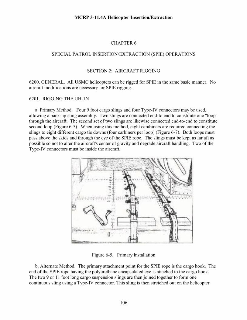
MCRP 3-11.4A Helicopter Insertion/Extraction
CHAPTER 6
SPECIAL PATROL INSERTION/EXTRACTION (SPIE) OPERATIONS
SECTION 2: AIRCRAFT RIGGING 6200. GENERAL. All USMC helicopters can be rigged for SPIE in the same basic manner. No aircraft modifications are necessary for SPIE rigging. 6201. RIGGING THE UH-1N a. Primary Method. Four 9 foot cargo slings and four Type-IV connectors may be used, allowing a back-up sling assembly. Two slings are connected end-to end to constitute one "loop" through the aircraft. The second set of two slings are likewise connected end-to-end to constitute second loop (Figure 6-5). When using this method, eight carabiners are required connecting the slings to eight different cargo tie downs (four carbiners per loop) (Figure 6-7). Both loops must pass above the skids and through the eye of the SPIE rope. The slings must be kept as far aft as possible so not to alter the aircraft's center of gravity and degrade aircraft handling. Two of the Type-IV connectors must be inside the aircraft.
Figure 6-5. Primary Installation b. Alternate Method. The primary attachment point for the SPIE rope is the cargo hook. The end of the SPIE rope having the polyurethane encapsulated eye is attached to the cargo hook. The two 9 or 11 foot long cargo suspension slings are then joined together to form one continuous sling using a Type-IV connector. This sling is then stretched out on the helicopter
106
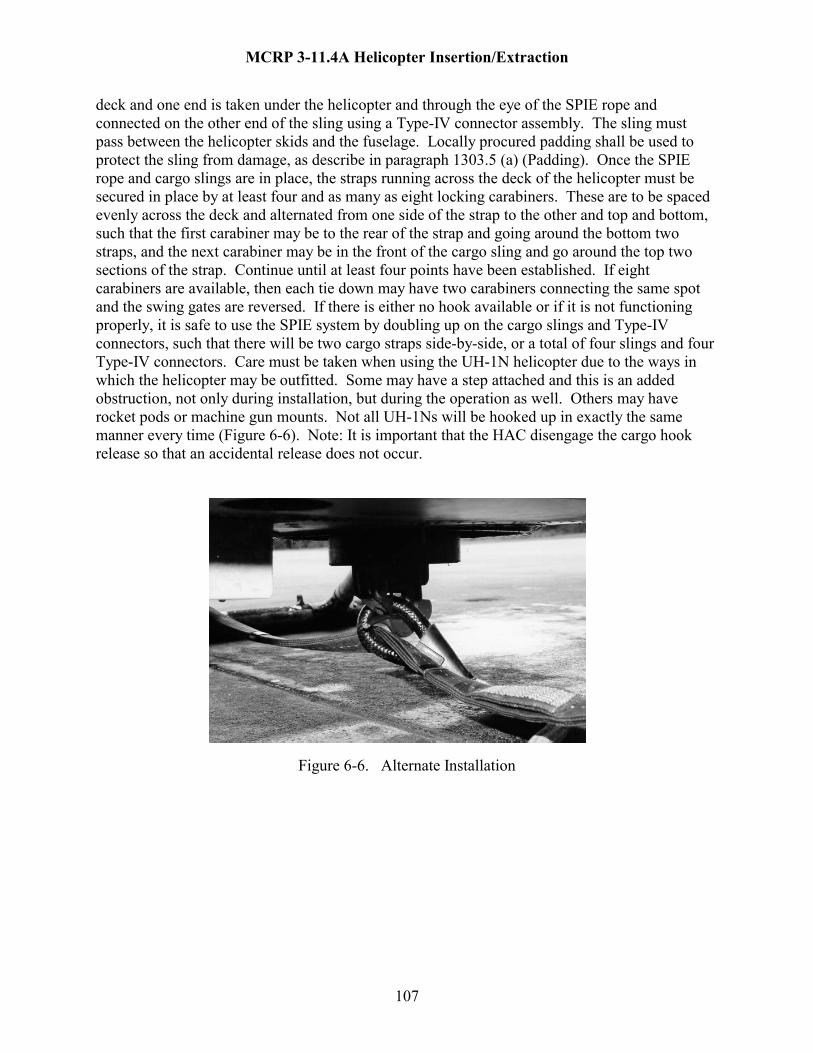
MCRP 3-11.4A Helicopter Insertion/Extraction
deck and one end is taken under the helicopter and through the eye of the SPIE rope and connected on the other end of the sling using a Type-IV connector assembly. The sling must pass between the helicopter skids and the fuselage. Locally procured padding shall be used to protect the sling from damage, as describe in paragraph 1303.5 (a) (Padding). Once the SPIE rope and cargo slings are in place, the straps running across the deck of the helicopter must be secured in place by at least four and as many as eight locking carabiners. These are to be spaced evenly across the deck and alternated from one side of the strap to the other and top and bottom, such that the first carabiner may be to the rear of the strap and going around the bottom two straps, and the next carabiner may be in the front of the cargo sling and go around the top two sections of the strap. Continue until at least four points have been established. If eight carabiners are available, then each tie down may have two carabiners connecting the same spot and the swing gates are reversed. If there is either no hook available or if it is not functioning properly, it is safe to use the SPIE system by doubling up on the cargo slings and Type-IV connectors, such that there will be two cargo straps side-by-side, or a total of four slings and four Type-IV connectors. Care must be taken when using the UH-1N helicopter due to the ways in which the helicopter may be outfitted. Some may have a step attached and this is an added obstruction, not only during installation, but during the operation as well. Others may have rocket pods or machine gun mounts. Not all UH-1Ns will be hooked up in exactly the same manner every time (Figure 6-6). Note: It is important that the HAC disengage the cargo hook release so that an accidental release does not occur.
Figure 6-6. Alternate Installation
107

MCRP 3-11.4A Helicopter Insertion/Extraction
Figure 6-7. Slings Secured By Carabiners 6202. RIGGING THE CH-46E. U-Shape Method of CH-46E Installation. The SPIE rope is attached utilizing two 9 or 11 foot cargo suspension slings and four Type-IV connectors. The cargo slings are passed through the encapsulated eye of the SPIE rope and attached to the outboard cargo tie down rings on the aircraft floor. The cargo slings will run forward and aft not laterally. Two tie-down rings are used for each cargo sling. Locally procured padding shall be used around the edge of the hellhole to protect the slings from damage, as described in paragraph 1303.6a (Padding). Not all of the tie-down rings are going to be in the exact same position on all helicopters. This will be one of the main considerations in deviating from the prescribed installation procedures. Installed properly, the cargo straps will hold the SPIE rope comfortably in the center of and slightly below the opening of the cargo hatch. Locking carabiners are attached close to all tie-down points and will ensure a backup in case of a faulty tie down ring. They also reduce the amount of movement in the cargo straps. A total of four locking carabiners will be used, one at each point with the gate facing up (Figure 6-8). Figure 6-8. CH-46E SPIE Rope Installation
108

CHAPTER 7
JACOB’S LADDER OPERATIONS
PARAGRAPH PAGE GENERAL 7100 110 OPERATIONAL CONSIDERATIONS 7101 110 SEQUENCE OF EVENTS 7102 111 AIRCRAFT RIGGING 7103 113 FIGURES 7-1 JACOB’S LADDER INSTALLATION 113
109
CHAPTER 7
JACOB’S LADDER OPERATIONS 7100. GENERAL. Jacob’s ladder like the SPIE system, was designed for use in emergency extractions where helicopters could not land. Unlike SPIE operations, employing Jacob’s ladder requires no special harness on the part of extracting personnel. Ladder operations are suitable for land, water, and waterborne extractions. In water extractions, swimmers mount the ladder directly from the water. In waterborne extractions, personnel mount the ladder from boats, barges, oil platforms, etc. 7101. OPERATIONAL CONSIDERATIONS a. Mission Aircraft. Jacob’s ladder is approved for use with the CH-46E only. b. Jacob’s ladder training will only be conducted by personnel and units whose operational requirement dictates extraction by this means. c. When employed over water, all users must utilize appropriate flotation equipment and be wet suit equipped during cold water operations. d. A thorough preflight brief must be conducted with all members involved in the training evolution. e. Night Operations
(1) No night time pickup may be conducted without previous daylight experience. This pertains to both aircrew and extract members.
(2) If night time training is conducted, the aircrew must be wearing NVDs with appropriate light conditions as directed by NVD policy. The aircrew must be night systems qualified to carry troops for the given light level condition ie. high light level or low light level.
(3) All aircraft equipment required for night flight must be fully functional.
(4) All lighting utilized in the extraction zone must be compatible with night vision goggle use. f. Jacob’s ladder training will be supervised by a certified HRST Master. As with all HRST operations, the HRST Master will require a communications helmet and a gunner's belt. g. Employment
(1) Over Land Extraction
110
(a) Maneuver to a stable 25 foot hover over the extraction site. (b) Maintain constant communications between HRST members. (c) The HAC will command, "DEPLOY THE LADDER," only when established in a stable hover. (d) Only 2 men at a time shall be on ladder. (e) When extraction is complete and the ladder is confirmed up and stowed, do not transition to forward flight until all passengers are seated, strapped in and crew chief has given the "CLEAR FOR FORWARD FLIGHT."
(2) Over Water Extraction. Same as overland when extracting a swimmer from water.
(3) Extraction from a maneuvering craft (a) Site craft and move into position astern. (b) Enter a 25 foot hover and slowly move over the craft until HRST Master signals ladder is in position. (c) Once the ladder is down and upon signal of the HRST Master, begin a slow 5 knot forward hover so as to provide taut ladder for the maneuvering craft. (d) Only 2 men at a time shall be on ladder. (e) Once all passengers are seated and strapped in and the HRST Master has retrieved the ladder, slowly transition up and forward after receiving, "CLEAR FOR FORWARD FLIGHT," from the crew chief. 7102. SEQUENCE OF EVENTS. Jacob’s ladder operations differ significantly from other rope suspension techniques. The following sequence of events will result in a safe extraction by Jacob’s ladder. a. Before Flight
(1) Inventory and inspect all Jacob’s ladder equipment.
(2) Connect and check operation of the ICS equipment to be utilized.
Check the location of the cutting device, it should be readily available.
(3) Conduct a joint brief for all personnel involved.
111
b. Extraction
(1) The crew chief, with the assistance of the HRST Master, will assist the pilot in positioning the helicopter over the extraction site of craft.
(2) "DEPLOY THE LADDER" - The HAC gives clearance to lower the ladder after the helicopter has established a stable hover.
(3) "LADDER OUT" - The HRST Master passes this advisory information to the HAC.
(4) The crew chief shall provide continuous information to the pilot in order to assist in maintaining the helicopter's position.
(5) The HRST Master watches for a "Thumbs Up" from the extraction team leader.
(6) If lifting from a boat, the HRST Master will advise the pilot to begin slow (5 knot) forward movement to present a taut ladder for the forward maneuvering craft.
(7) "CLIMBER #_____INSIDE" - The HRST Master provides the HAC with a count of extract personnel as they enter the aircraft.
(8) As climbers enter the aircraft, the crew chief directs them to seating.
(9) In the event a climber becomes entangled during the climb, the HAC shall be notified immediately.
(10) An entangled climber has the option of reattempting the climb or signaling the boat coxswain to move clear so that he may fall free into the water.
(11) If over land, a stable hover must be held to enable the member to climb back down the ladder or be pulled up. c. Emergency Procedures:
(1) Ladder Entanglement
(a) If a climber becomes entangled on the ladder, retain a stable hover until he frees himself or is pulled into aircraft. (b) If the ladder becomes entangled on an obstacle (without climber aboard) hold position until the ladder is disconnected from the aircraft. Should safety of flight dictate, "CUT LADDER", shall be commanded by the HAC only. NOTE: "CUT LADDER" must be thoroughly briefed prior to flight.
112

(c) If the ladder becomes entangled on an obstacle with climber aboard, hold position to allow a dismount or climb up. If safety of flight dictates, the HAC may order, "CUT LADDER". A cutaway must be signaled to the climber by the HRST Master prior to action.
(2) Emergency Decent. Climbers should move away from the aircraft's six o'clock position upon contact with the ground or water. 7103. AIRCRAFT RIGGING. Only the CH-46E is authorized to rig for Jacob’s ladder operations. a. Installation instructions that follow are applicable to double attachment of suspension slings for maximum safety. Locally procured padding (usually sections of fire hose) will be used to protect slings from damage, as described in paragraph 1303(f)(1) (Padding). b. The Jacob’s ladder is attached using six Stubai snaplinks. The nylon slings are attached at 2 inboard tie down rings located at station 408 and further attached on an inboard ring at station 390 as a safety back-up. The ladder will be transported rolled up until ready for employment (Figure 7-1). c. The above attachment may be made with the fast rope Scholomer frame attached in place. This allows additional hand hold positions for climbing onto the aircraft and a hand hold safety barrier for the HRST Master.
Figure 7-1. Jacob’s Ladder Installation
113

114

MCRP 3-11.4A Helicopter Insertion/Extraction
APPENDIX A
HRST MISSION BRIEF TO HRST MEMBERS 1. Hold muster and prepare a passenger manifest. 2. GENERAL OPERATIONS INFORMATION
a. HRST MASTER
b. SIO
c. Area of HRST Operation:
d. Type of HRST and method to be used:
e. Type of helicopter:
f. Total number of ropers to exit:
g. Location of rope station(s) in aircraft:
h. Location of safety vehicle:
i. Location of Corpsman: j. Other personnel:
3. HRST PREPARATION
a. Personnel (1) Corpsman: (2) Drivers: (3) Working party:
b. Formation time:
c. Type of transportation:
d. HRST time:
e. Number of sticks:
1
MCRP 3-11.4A Helicopter Insertion/Extraction
f. Number of operations
g. Exit sequence, by name:
h. Safety checks (HRST Master/Assistant HRST Master) 4. HRST TRAINING AREA
a. Location (map).
b. Aerial photograph.
c. Location and type of safety vehicle.
d. Obstacles on or near HRST training area.
e. Flight plan.
f. Exit point. 5. ACTIONS IN THE LOADING AREA
a. Muster.
b. Equipment and safety check.
c. Loading order and seating arrangement.
d. Review HRST commands hand and arm signals. 6. ACTIONS IN THE HELICOPTER
a. Fasten seatbelts, unbuckle on HRST Master's signals only.
b. Watch for HRST Master's signals.
c. HRST Master will direct hook up. (1) Hold brake hand out to grasp rappel line (rappel). (2) Put on brake while moving to exit point (rappel). (3) HRST Master will indicate when ropers have the correct amount of slack (rappel).
d. Assume "L" position.
2

MCRP 3-11.4A Helicopter Insertion/Extraction
e. "GO" on signal. 7. ACTION ON RAPPEL
a. Keep good body position.
b. Make positive brakes.
c. Make at least three brakes during descent. (rappel) 8. ACTION ON GROUND
a. Belayman will move to ropers front and grasp rope. (rappel)
b. Back up, not stepping on the rope, hold the rope to your rear and with your brake hand. Place your left hand above the snaplink to prevent the rope from snapping up into your face. (rappel)
c. Once clear, hold hands on top of your head and sound off with last name, "____________________ OFF RAPPEL".
d. Move to the assembly area. 9. ZONE CONTROL
a. Radio call sign.
b. Frequency and alternate frequency.
c. Visual signals and panels.
d. Radio check prior to operation.
e. Actions for radio failure. 10. MALFUNCTIONS
a. If the roper cannot complete rappel due to a "Hung Roper": (1) Put brake on, stabilize, and wave hand back and forth. (2) The HRST Master will have the pilot move to a place where he can lower roper to the ground. If roper cannot be lowered to the ground, the HRST Master will attempt to lower a safety line to the roper and establish a belay. Ropers will not be cut loose until reasonably close to the ground: (Less than ten feet).
3
MCRP 3-11.4A Helicopter Insertion/Extraction
b. If roper's hand slips off the rope: (1) The belayman will put tension on the rope and break his fall. (2) The belayman will slowly lower the roper to the ground. 11. DUTIES OF THE BELAY MAN
a. Watch the roper, if he gets out of control, or loses his grip on the rope immediately take action to slow or stop his rappel.
b. Maintain control of the running end of the rope by holding the running end around your body and be prepared to put a braking action on the rope.
c. Give the roper enough slack so that the belay man does not interfere with his brake.
d. Should the helicopter have to descend, maintain a taut rope while backing away from the helicopter.
e. Belay men shall wear goggles.
f. Gloves shall not be worn while belaying.
4

MCRP 3-11.4A Helicopter Insertion/Extraction
APPENDIX B
HRST BRIEF TO AIRCREW 1. PERSONNEL ROLL CALL
a. HRST Master.
b. Assistant HRST Master (s).
c. Safety Insert Officer (SIO).
d. HRST Personnel.
e. Helicopter Aircraft Commander (HAC).
f. Co-pilot.
g. Crew Chief. 2. OPERATIONAL DATA
a. TAR or FRAG Number.
b. Takeoff Time.
c. Insertion and Extraction Time.
d. Location of Insertion and Extraction.
e. Hover Altitude.
f. Number of Inserts and Extracts.
g. Number of Personnel per Insert and Extracts. 3. INSERTION AND EXTRACTION ZONE IDENTIFICATION
a. Characteristics of the zone.
b. Obstacles near the zone.
c. Altitude of the zone.
d. Location of corpsman.
1

MCRP 3-11.4A Helicopter Insertion/Extraction
e. Zone marking.
f. Control of ramp, doors and hatches. 4. ORGANIZATION
a. Organization for movement (2 or more aircraft).
b. Number of men in aircraft.
c. Location of SIO, HRST, Master and Assistant HRST Master(s).
d. Number of rope stations.
e. Length of rope.
f. Equipment needed (i.e. GUNNER'S BELT, ICS, CRANIALS, SAFETY STRAP...). 5. SEQUENCE OF EVENT AND RESPONSIBILITIES
a. Communication.
b. Grid coordinates.
c. HRST commands and hand and arm signals. 6. AIRCRAFT EMERGENCY PROCEDURES
a. Personnel inside the aircraft will remain seated and await instructions from the HRST Master or crew chief.
b. Personnel on the ground will move to a pre-designated position from the aircraft.
c. Personnel on ropes will attempt to lower themselves to the deck as quickly as possible.
d. Personnel on SPIE rope should attempt to cut the line over water if a safe landing cannot be accomplished.
e. "CUT ROPE" procedures. 7. If a roper is knotted on the rope (Hung Roper) the aircraft shall attempt to lower him to the ground.
2

MCRP 3-11.4A Helicopter Insertion/Extraction
APPENDIX C
HRST COMMANDS 1. HRST commands fall into two categories: mandatory and advisory. A thorough understanding of all HRST commands is essential. HRST commands are a vital link to good crew coordination and shall be discussed in detail during all preflight briefs. 2. CHALLENGE AND REPLY. Whenever possible the challenge and reply method of passing and receiving commands will be utilized. This will ensure that a command sent has been received. 3. MANDATORY COMMANDS ABORT - Any HRST member. Cease rope operation immediately. BRAKE - HRST Master to roper. Stop rappel and hold position on the rope until cleared to descent. CHECK EQUIPMENT - HRST Master to ropers. Check all personal equipment and that of nearest team member. Give a "thumbs up or down" reply. CLEAR FOR TAKEOFF - Crew chief to HAC. Ropers and personnel are clear of obstacles. CLEAR FOR FORWARD FLIGHT - Crew chief to HAC. Ropers and personnel are clear of obstacles. Transition to forward flight can be accomplished safely. CLEAR TO DESCEND - Crew chief to HAC. Ropers and personnel are clear of obstacles. A controlled vertical descent is recommended. CUT ROPE - HAC to HRST Master. A last ditch action to reduce injuries or save lives. This call can only be given by the HAC. DEPLOY THE ROPE - HAC to HRST. Established in a stable hover. Clear to lower rope to the deck. GO - HRST Master to roper. Begin descent. HOLD - Crew chief to pilot. Maintain a steady aircraft position. HRST Master to roper. Stop in position. Remain steady. HOOK UP - HRST Master to roper. Attach snaplink to rope. FIRST MAN OFF - HRST Master to HAC. During SPIE extract, signal pilot to note altitude.
1
MCRP 3-11.4A Helicopter Insertion/Extraction
LOCK IN - HRST Master to roper. During fast rope, hold position by locking legs and feet around rope. READY TO LIFT - HRST Master to HAC. During SPIE, received a "thumb up" form team leader cleared to begin vertical extract. RETRIEVE OR RELEASE THE ROPE - HAC to HRST Master. After assurance that ropers are clear of rope, directs that ropes be pulled into or released from aircraft. ROPE CLEAR - HRST Master to HAC. Ropes either pulled inside the aircraft or have been dropped to the deck, or have been staged by belay men. ROPERS ON THE DECK - HRST Master to HAC. During SPIE dismount, last roper has reached the ground and is unhooking. ROPE OUT - HRST Master to HAC. After clearance to deploy the rope, informs HAC that the rope is deployed. STRAP IN - Any HRST Member. Take seat and fasten seat belt or safety strap. TAKE POSITION - HRST Master to roper. Take final position prior to beginning descent. "L" position for rappel. Grasp the rope for fast rope. UNBUCKLE - HRST Master to roper. Take final position prior to beginning descent. "L" position for rappel. Grasp the rope for fast rope. 4. ADVISORY COMMANDS GET READY - HRST Master to ropers. Approximately 1 minute out; make final personal inspections of equipment. FIRST MAN OUT- HRST Master to HAC. Counts out ropers as they begin descent. SLIDE: LEFT, RIGHT, FORWARD, BACK, UP or DOWN - Crew chief to HAC. Directions for the aircraft to position over target area. THREE MINUTES and ONE MINUTE - HAC to HRST Master. Approximate time to target area. 25 FEET, 10 FEET and 5 FEET - HRST Master to HAC. During dismount, approximate distance of roper to the deck. 5. HAND AND ARM SIGNALS ABORT - Slashing motion of right hand across throat.
2

MCRP 3-11.4A Helicopter Insertion/Extraction
EMERGENCY - Right hand slapping motion on top of head. BRAKE, HOLD or LOCK-IN - Clenched fist. CLEAR ROPE or OFF BELAY - Both hands on top of head. EQUIPMENT NOT GOOD - "Thumbs down". Point to bad equipment. CUT ROPE - A "Hacking" motion of a hand on the other forearm. DEPLOY THE ROPE - Two hands "pushing away" motion. GO - Point down the rope. READY TO LIFT - "Thumbs up" followed by upward motion of right palm. RETRIEVE ROPE - "Pulling in" motion with both arms. STRAP IN - Point to seats and motion both fists together at belt buckle. SLIDE (DIRECTION) - Open palm motion into direction desired movement. TAKE POSITION - Point at rope station. UNBUCKLE - Motion both fists away from belt buckle. _____ MINUTE(S) - Point to watch then hold up the number of fingers.
3

MCRP 3-11.4A Helicopter Insertion/Extraction
1
APPENDIX D
ROPE LOG (Rappel)
Inspect rope for damage and excessive wear each time it is deployed and again after each use. Immediately retire all suspect ropes. Unit Rope ID: NSN: MFR. Lot No: Manufacturer: Date Purchased: Date in Service: Color: Length: Diameter: Type Rope: Date No. Type of Rope Grade Inspector Used Rappels Rappels and Comments Initials
Page ___ of ___

MCRP 3-11.4A Helicopter Insertion/Extraction
APPENDIX E
RAPPEL TOWER INSPECTION 1. Is the tower structurally sound? 2. Are all open areas (above 4’) guarded with guard rails? 3. Are all guard rails a minimum of 42” high and capable of withstanding a side force of 200 lbs? 4. Are toe boards installed in all areas where personnel could pass underneath? 5. Do all stairs/fixed ladders comply with OSHA standards? 6. Do all tower rope stations have three anchor points each? 7. Have all anchor points been load tested? 8. Are all anchor points in good condition and free of corrosion, sharp edges, burrs, etc? 9. Is the tower deck free of trip/slip hazards (water, protruding nails/bolts, splinters, etc)? 10. Is the rappel wall face and the fastrope area free of protrusions, broken or loose boards? 11. Does the tower deck and the stairway tread have a non-skid surface? 12. Is there padding on all edges that ropes and/or personnel cross? 13. Is the edge padding in good condition and securely fastened? 14. Are there any signs of insect infestation? 15. Is the landing area free of obstructions and hazards? 16. Do the landing areas consist of a cushioning material (recommend 24” non-compressed depth of wood chips or mulch)? 17. Has the landing area been loosened up prior to use and, if large number of students are rappelling, loosened up again during training? 18. Are all structural areas of the tower, that a rappeller might contact during rappel/fast rope operations, properly padded?
1
MCRP 3-11.4A Helicopter Insertion/Extraction
19. Are all structural padding in good condition and securely fastened? 20. Are all areas, that pose a trip hazard or head hazard, marked in yellow? 21. Is the tower platform and all rappel rope stations accessible without having to climb over any obstacles (i.e: guard rails, support cables, etc.)? General Recommendations: 1. Ensure that the rappel tower is placed on a regularly scheduled inspection/maintenance program. This is normally on a quarterly basis and covers such items as: inspection, repair (as required), replacement/repair of any padding used, replenishment of wood mulch, etc.. This may be done by command personnel, public works department, or private contract. 2. The tower should be inspected periodically by a qualified engineer (time intervals to be established by the engineer based on the type of structure, usage, climatic conditions, etc). A copy of the engineer’s certification should be kept on file. The certification should cover the load test rating of the existing rope anchor points.
2

MCRP 3-11.4A Helicopter Insertion/Extraction
Appendix F
Glossary
Acronyms and Abbreviations
ETA Estimated time of arrival HAC Helicopter aircraft commander HRST Helicopter rope suspension training ICS Inter communication system MALS Marine Aviation Logistics Squadron NAVAIR Naval Air Systems Command NVG Night vision goggles PFD Personal flotation device SIO Safety insert officer SPIE Special insertion extraction SRB/OQR Service record book/officer qualification record

MCRP 3-11.4A Helicopter Insertion/Extraction
Appendix G
References and Related Publications Naval Publications NAVAIR 13-45-2 NWP 3-22.5–CH-46E NWP 3-22.5-CH-53E NWP 3-22.5-UH-1N OPNAV 3710.7M Marine Corps Publications P5102.1 Ground Safety Reporting P3500.27 Operational Risk Management