mcp1630 sepic automotive led driver reference design
TRANSCRIPT

© 2011 Microchip Technology Inc. DS51955A
MCP1630SEPIC Automotive LED Driver
Reference Design

Note the following details of the code protection feature on Microchip devices:• Microchip products meet the specification contained in their particular Microchip Data Sheet.
• Microchip believes that its family of products is one of the most secure families of its kind on the market today, when used in the intended manner and under normal conditions.
• There are dishonest and possibly illegal methods used to breach the code protection feature. All of these methods, to our knowledge, require using the Microchip products in a manner outside the operating specifications contained in Microchip’s Data Sheets. Most likely, the person doing so is engaged in theft of intellectual property.
• Microchip is willing to work with the customer who is concerned about the integrity of their code.
• Neither Microchip nor any other semiconductor manufacturer can guarantee the security of their code. Code protection does not mean that we are guaranteeing the product as “unbreakable.”
Code protection is constantly evolving. We at Microchip are committed to continuously improving the code protection features of ourproducts. Attempts to break Microchip’s code protection feature may be a violation of the Digital Millennium Copyright Act. If such actsallow unauthorized access to your software or other copyrighted work, you may have a right to sue for relief under that Act.
Information contained in this publication regarding deviceapplications and the like is provided only for your convenienceand may be superseded by updates. It is your responsibility toensure that your application meets with your specifications.MICROCHIP MAKES NO REPRESENTATIONS ORWARRANTIES OF ANY KIND WHETHER EXPRESS ORIMPLIED, WRITTEN OR ORAL, STATUTORY OROTHERWISE, RELATED TO THE INFORMATION,INCLUDING BUT NOT LIMITED TO ITS CONDITION,QUALITY, PERFORMANCE, MERCHANTABILITY ORFITNESS FOR PURPOSE. Microchip disclaims all liabilityarising from this information and its use. Use of Microchipdevices in life support and/or safety applications is entirely atthe buyer’s risk, and the buyer agrees to defend, indemnify andhold harmless Microchip from any and all damages, claims,suits, or expenses resulting from such use. No licenses areconveyed, implicitly or otherwise, under any Microchipintellectual property rights.
DS51955A-page 2
Trademarks
The Microchip name and logo, the Microchip logo, dsPIC, KEELOQ, KEELOQ logo, MPLAB, PIC, PICmicro, PICSTART, PIC32 logo, rfPIC and UNI/O are registered trademarks of Microchip Technology Incorporated in the U.S.A. and other countries.
FilterLab, Hampshire, HI-TECH C, Linear Active Thermistor, MXDEV, MXLAB, SEEVAL and The Embedded Control Solutions Company are registered trademarks of Microchip Technology Incorporated in the U.S.A.
Analog-for-the-Digital Age, Application Maestro, chipKIT, chipKIT logo, CodeGuard, dsPICDEM, dsPICDEM.net, dsPICworks, dsSPEAK, ECAN, ECONOMONITOR, FanSense, HI-TIDE, In-Circuit Serial Programming, ICSP, Mindi, MiWi, MPASM, MPLAB Certified logo, MPLIB, MPLINK, mTouch, Omniscient Code Generation, PICC, PICC-18, PICDEM, PICDEM.net, PICkit, PICtail, REAL ICE, rfLAB, Select Mode, Total Endurance, TSHARC, UniWinDriver, WiperLock and ZENA are trademarks of Microchip Technology Incorporated in the U.S.A. and other countries.
SQTP is a service mark of Microchip Technology Incorporated in the U.S.A.
All other trademarks mentioned herein are property of their respective companies.
© 2011, Microchip Technology Incorporated, Printed in the U.S.A., All Rights Reserved.
Printed on recycled paper.
ISBN: 978-1-61341-606-8
© 2011 Microchip Technology Inc.
Microchip received ISO/TS-16949:2009 certification for its worldwide headquarters, design and wafer fabrication facilities in Chandler and Tempe, Arizona; Gresham, Oregon and design centers in California and India. The Company’s quality system processes and procedures are for its PIC® MCUs and dsPIC® DSCs, KEELOQ® code hopping devices, Serial EEPROMs, microperipherals, nonvolatile memory and analog products. In addition, Microchip’s quality system for the design and manufacture of development systems is ISO 9001:2000 certified.

MCP1630 SEPIC AUTOMOTIVE LEDDRIVER REFERENCE DESIGN
Table of Contents
Preface ........................................................................................................................... 5Introduction...............................................................................................................5Document Layout .....................................................................................................5Conventions Used in this Guide ...............................................................................6Recommended Reading...........................................................................................7The Microchip Web Site ...........................................................................................7Customer Support ....................................................................................................7Document Revision History.................................................................................... 8
Chapter 1. Product Overview1.1 Introduction ........................................................................................................91.2 Features ..........................................................................................................101.3 Device Summary .............................................................................................101.4 Technical Specifications ..................................................................................111.5 Functional Description .....................................................................................121.6 What the MCP1630 SEPIC Automotive LED Driver Reference Design Kit Includes ......................................................................................................... 12
Chapter 2. Installation and Operation2.1 Getting Started ................................................................................................132.2 Setup Procedure .............................................................................................132.3 Evaluating the Application ...............................................................................152.4 Firmware Description .......................................................................................152.5 Programming the PIC12F683 Microcontroller ............................................... 16
Appendix A. Schematic and LayoutsA.1 Introduction .....................................................................................................17A.2 Board – Schematic ..........................................................................................18A.3 Board – Top Copper and Pads .......................................................................19A.4 Board – Top Copper Pads and Silk .................................................................20A.5 Board – Top Silk and Pads .............................................................................21A.6 Board – Bottom Copper and Pads ................................................................ 22
Appendix B. Bill of Materials (BOM)Appendix C. Firmware Flowchart
C.1 MCP1630 SEPIC Automotive LED Driver Reference Design Firmware Flowchart ............................................................................................ 25
Appendix D. Test Points and WaveformsD.1 Test Points Description ...................................................................................27D.2 Waveforms Examples ................................................................................... 28
Worldwide Sales and Service .................................................................................... 34
© 2011 Microchip Technology Inc. DS51955A-page 3

MCP1630 Sepic Automotive LED Driver Reference Design
DS51955A-page 4 © 2011 Microchip Technology Inc.
MCP1630 SEPIC AUTOMOTIVE LEDDRIVER REFERENCE DESIGN
Preface
INTRODUCTIONThis chapter contains general information that will be useful to know before using the MCP1630 SEPIC Automotive LED Driver Reference Design User’s Guide. Items discussed in this chapter include:• Document Layout• Conventions Used in this Guide• Recommended Reading• The Microchip Web Site• Customer Support• Document Revision History
DOCUMENT LAYOUTThis document describes how to use the MCP1630 SEPIC Automotive LED Driver Reference Design User’s Guide as a development tool to emulate and debug firmware on a target board. The manual layout is as follows:• Chapter 1. “Product Overview” – Important information about the MCP1630
SEPIC Automotive LED Driver Reference Design. • Chapter 2. “Installation and Operation” – This chapter includes a detailed
description of each function of the demonstration board and instructions for how to begin using the board.
• Appendix A. “Schematic and Layouts” – Shows the schematic and layout diagrams for the MCP1630 SEPIC Automotive LED Driver Reference Design.
• Appendix B. “Bill of Materials (BOM)” – Lists the parts used to build the MCP1630 SEPIC Automotive LED Driver Reference Design.
• Appendix C. “Firmware Flowchart” – Shows the board flowchart.• Appendix D. “Test Points and Waveforms” – Describes the main test points
and waveforms for the MCP1630 SEPIC Automotive LED Driver Reference Design.
NOTICE TO CUSTOMERS
All documentation becomes dated, and this manual is no exception. Microchip tools and documentation are constantly evolving to meet customer needs, so some actual dialogs and/or tool descriptions may differ from those in this document. Please refer to our web site (www.microchip.com) to obtain the latest documentation available.
Documents are identified with a “DS” number. This number is located on the bottom of each page, in front of the page number. The numbering convention for the DS number is “DSXXXXXA”, where “XXXXX” is the document number and “A” is the revision level of the document.
For the most up-to-date information on development tools, see the MPLAB® IDE online help. Select the Help menu, and then Topics to open a list of available online help files.
© 2011 Microchip Technology Inc. DS51955A-page 5

MCP1630 Sepic Automotive LED Driver Reference Design
CONVENTIONS USED IN THIS GUIDEThis manual uses the following documentation conventions:
DOCUMENTATION CONVENTIONSDescription Represents Examples
Arial font:Italic characters Referenced books MPLAB® IDE User’s Guide
Emphasized text ...is the only compiler...Initial caps A window the Output window
A dialog the Settings dialogA menu selection select Enable Programmer
Quotes A field name in a window or dialog
“Save project before build”
Underlined, italic text with right angle bracket
A menu path File>Save
Bold characters A dialog button Click OKA tab Click the Power tab
N‘Rnnnn A number in verilog format, where N is the total number of digits, R is the radix and n is a digit.
4‘b0010, 2‘hF1
Text in angle brackets < > A key on the keyboard Press <Enter>, <F1>Courier New font:Plain Courier New Sample source code #define START
Filenames autoexec.bat
File paths c:\mcc18\hKeywords _asm, _endasm, staticCommand-line options -Opa+, -Opa-
Bit values 0, 1Constants 0xFF, ‘A’
Italic Courier New A variable argument file.o, where file can be any valid filename
Square brackets [ ] Optional arguments mcc18 [options] file [options]
Curly brackets and pipe character: |
Choice of mutually exclusive arguments; an OR selection
errorlevel 0|1
Ellipses... Replaces repeated text var_name [, var_name...]
Represents code supplied by user
void main (void) ...
DS51955A-page 6 © 2011 Microchip Technology Inc.

Preface
RECOMMENDED READINGThis user’s guide describes how to use the MCP1630 SEPIC Automotive LED Driver Reference Design User’s Guide. Other useful documents are listed below. The follow-ing Microchip documents are available and recommended as supplemental reference resources.• MCP1630/MCP1630V Data Sheet – “High-Speed, Microcontroller-Adaptable,
Pulse Width Modulator” (DS21896)• PIC12F683 Data Sheet – “8-Pin Flash-Based, 8-Bit CMOS Microcontrollers
with nanoWatt Technology” (DS41211)• MCP1790 Data Sheet – “70 mA, High Voltage Regulator” (DS22075)• MCP1415/16 Data Sheet – “Tiny 1.5A, High-Speed Power MOSFET Driver”
(DS22092)• AN1137 – “Using the MCP1631 Family to Develop Low-Cost
Battery Chargers” (DS01137)
THE MICROCHIP WEB SITEMicrochip provides online support via our web site at www.microchip.com. This web site is used as a means to make files and information easily available to customers. Accessible by using your favorite Internet browser, the web site contains the following information:• Product Support – Data sheets and errata, application notes and sample
programs, design resources, user’s guides and hardware support documents, latest software releases and archived software
• General Technical Support – Frequently Asked Questions (FAQs), technical support requests, online discussion groups, Microchip consultant program member listing
• Business of Microchip – Product selector and ordering guides, latest Microchip press releases, listing of seminars and events, listings of Microchip sales offices, distributors and factory representatives
CUSTOMER SUPPORTUsers of Microchip products can receive assistance through several channels:• Distributor or Representative• Local Sales Office• Field Application Engineer (FAE)• Technical SupportCustomers should contact their distributor, representative or field application engineer (FAE) for support. Local sales offices are also available to help customers. A listing of sales offices and locations is included in the back of this document.Technical support is available through the web site at: http://support.microchip.com
© 2011 Microchip Technology Inc. DS51955A-page 7

MCP1630 Sepic Automotive LED Driver Reference Design
DOCUMENT REVISION HISTORY
Revision A (September 2011)• Initial Release of this Document.
DS51955A-page 8 © 2011 Microchip Technology Inc.
MCP1630 SEPIC AUTOMOTIVE LEDDRIVER REFERENCE DESIGN
Chapter 1. Product Overview
1.1 INTRODUCTIONThe MCP1630 Sepic Automotive LED Driver Reference Design is a step-up/down, Switch mode, DC-DC converter used for powering LED applications. The demo board provides a 350 mA (700 mA, with hardware modification) constant current source. Other output currents can be obtained with minor modifications to the board components’ values.The MCP1630 Sepic Automotive LED Driver Reference Design sustains the high-voltage peaks that can be found in typical automotive applications. This board provides useful information about typical high-voltage applications that can be found in the automotive field. The MCP1630 Sepic Automotive LED Driver Reference Design utilizes Microchip’s MCP1630 high-speed, Pulse-Width Modulator (PWM) device. The 8-pin MCP1630 device contains all the analog components necessary for a peak current switch-mode control loop, including an error amplifier, a PWM comparator and a high-current driver output pin. The switching frequency and the maximum duty cycle for the MCP1630 are determined by an external clock source.An 8-pin PIC12F683 microcontroller is used to provide a 330 kHz switching clock for the MCP1630 device. In addition, the PIC12F683 firmware supervises the input and output voltage, and can optionally dim the LEDs when a button is attached.In this reference design, the MCP1630 device is used for Peak Current Mode Control in a SEPIC power train circuit. Because the duty cycle exceeds 50%, a ramp generator provides an additional reference signal to the MCP1630 for slope compensation.
Note: This application uses a Peak Current Mode Control. Use only the MCP1630 device option for this board.
© 2011 Microchip Technology Inc. DS51955A-page 9

MCP1630 Sepic Automotive LED Driver Reference Design
1.2 FEATURESThe MCP1630 Sepic Automotive LED Driver Reference Design has the following features:• Compact size with high output power• Can operate in Buck (step-down) or Boost (step-up) mode• Sustains voltage stresses typically found in automotive products:
42 VIN for 180 ms• High efficiency over the entire operating input and output voltage ranges:
85% typical• Maximum Output Current = 350 mA; this value can be modified with minor
changes in hardware • Maximum Output Power = 18W• Optional software dimming control for both methods: PWM or Current mode • Preprogrammed source code • The switching frequency, maximum duty cycle and the MCP1630 reference
voltage can be modified in firmware• Additional application functions can be implemented in firmware
1.3 DEVICE SUMMARYThe MCP1630 Sepic Automotive LED Driver Reference Design uses the following devices:• MCP1630 High-Speed Pulse-Width Modulator IC – When used in conjunction with
a microcontroller, the MCP1630 controls the power system duty cycle to provide output current and/or voltage regulation.
• PIC12F683 Microcontroller (8-bit MCU) – Used to generate the MCP1630’s reference voltage, the oscillator signal at 330 kHz, and to provide additional software functions.
• MCP1790 HV LDO Regulator – Used to supply the regulated voltage to the PIC12F683 and MCP1630. The MCP1790 is capable of delivering 70 mA and sustaining 42V surge voltage on input for 180 ms (30 seconds repetition rate).
• MCP1416 – Is a high-speed MOSFET driver, capable of providing 1.5A of peak current for driving the switching power transistor.
DS51955A-page 10 © 2011 Microchip Technology Inc.

Product Overview
1.4 TECHNICAL SPECIFICATIONS• Input Voltage = 9V to 16V (surge voltage of 42V for maximum 180 ms, 30 seconds
repetition rate)• Software Configurable Under Voltage Lock-Out Circuit (UVLO) and Over Voltage
Lock-Out Circuit (OVLO) (8V and 17V default thresholds)• Software Configurable Load Disconnect Protection • Typical Output Current = 350 mA• Maximum Output Current = 700 mA (with hardware modifications)• Typical Output Power = 18W (maximum 20W at TA = +25°C) • Fully Protected Against Short-Circuit and No-Load ConditionFigure 1-1 shows a simplified block diagram of the application.
FIGURE 1-1: MCP1630 Sepic Automotive LED Driver Reference Design Block Diagram.
GNDIN
+5V
+5V OUT
Ramp GeneratorSlope Compensation
Circuit
4 OSC
5 GND
1COMP
EA
PWM COMP
OUTPUTDRIVER
6
VEXT
3CS
2FB
8REF
7MCP1630
MCP1790
Compensation Network
1
2
6
3
4
7
5CLOCK
Aux.
Dimming
8 PIC12F683
VSS
VDD
GP5
GP1
GP4 VIN Sense
Reference
ISENSE
GP2
GP3
GP0
Voltage Filter
CurrentSenseResistor
LED String
SEPIC Power Train
+VIN
VIN SenseSurgeProtection
MCP1416MOSFET Driver
CS
© 2011 Microchip Technology Inc. DS51955A-page 11

MCP1630 Sepic Automotive LED Driver Reference Design
1.5 FUNCTIONAL DESCRIPTIONThe MCP1630 device provides all the analog functions necessary to implement a Peak Current Mode PWM DC-DC Converter. The power train is based on the Single-Ended Primary Inductor Converter (SEPIC) topology. This topology offers the buck-boost functionality and also has non-pulsating input current.The converter provides adjustable constant current at the output, necessary to drive high-power LED applications.The MCP1630 PWM controller requires an external clock for operation. This clock is provided by an external 8-bit microcontroller, PIC12F683. The PWM frequency and the maximum duty cycle are set by this clock.The output (load) current is sensed with a 0.5Ω shunt resistor (R17 and R18). The voltage across this shunt resistor is compared with the reference voltage by the MCP1630 device’s PWM controller. The reference voltage for the MCP1630 device is also provided by PIC12F683, at the VREF pin (Pin 8). R4, R3 and C2 form a low-pass filter that smooths the PWM signal produced by the PIC® microcontroller. The maximum output current is set by the R4 and R3 voltage dividers. The duty cycle of the PWM signal is adjusted in eight steps.The output current is calculated with Equation 1-1:
EQUATION 1-1:
Because the operating duty cycle is bigger than 50%, a slope compensation circuit is required to avoid subharmonic oscillations that occur in Peak Current mode controllers. A ramp generator is constructed with Q1 and the associated components. The ramp is then summed with the inductor current, measured across R9 and R10 resistors. A 100V VDS MOSFET transistor is also used in this application. The MCP1416 MOSFET driver drives the gate of this transistor. This is necessary because the high-voltage transistors usually have high gate charge and also require at least 7V for gate-to-source voltage.
1.6 WHAT THE MCP1630 SEPIC AUTOMOTIVE LED DRIVER REFERENCE DESIGN KIT INCLUDES
The MCP1630 Sepic Automotive LED Driver Reference Design includes:• MCP1630 Sepic Automotive LED Driver Reference Design (102-00323)• Important Information Sheet
IOUTVREF0.5------------=
Where:
VREFmaxR3
R3 R4+---------------------⎝ ⎠⎛ ⎞ 5V 178=× mV=
IOUTmax178mV
0.5----------------- 357mA==
Note: The MCP1416 MOSFET driver must be protected against input voltage surges. This protection is ensured by R6 and D1.
DS51955A-page 12 © 2011 Microchip Technology Inc.
MCP1630 SEPIC AUTOMOTIVE LEDDRIVER REFERENCE DESIGN
Chapter 2. Installation and Operation
2.1 GETTING STARTEDThe MCP1630 Sepic Automotive LED Driver Reference Design is fully assembled and tested. The board requires the use of an external input voltage source (9V to 16V) and an external LED load, provided by Microchip.
2.1.1 Additional Tools Required for Operation1. A DC power supply, a bench supply that can produce 12V, 2.5A, is recommended
to operate the board at the full rated power. 2. An oscilloscope and/or a multi-meter to observe the waveforms and measure the
electrical parameters (optional).
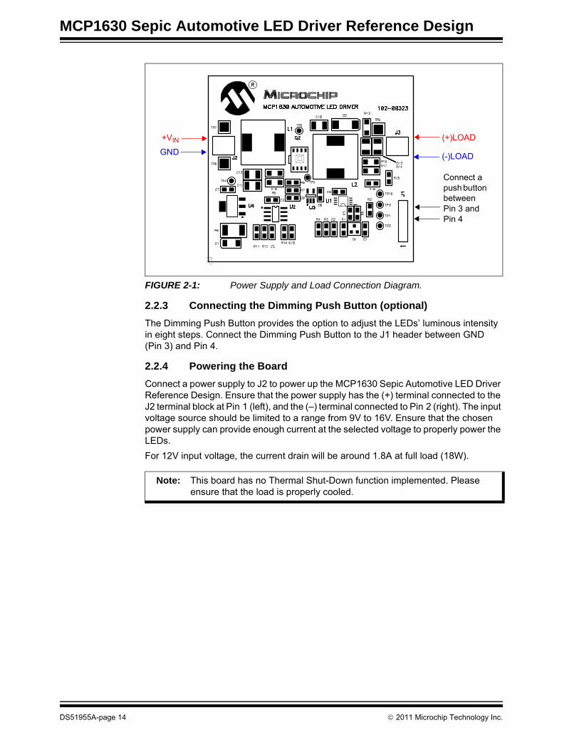
2.2 SETUP PROCEDURE To operate the MCP1630 Sepic Automotive LED Driver Reference Design, the following steps must be completed:1. Attach an LED load (or dummy load) to the Output Connector J3 (observe the
polarity).2. Attach the push button to the J1 header (between Pins 3 and 4 is optional).3. Connect a power supply to the Input Connector J2 (observe the polarity).Detailed instructions are provided below for each step.
2.2.1 Demo Board Output Current ConfigurationThe board is configured to deliver a maximum of 350 mA to the LEDs’ load. UVLO and OVLO thresholds are set to 8V and 17V, respectively. The maximum output voltage is set to be approximately 55V.
2.2.2 Connecting the Load
A string of up to sixteen white LEDs (1W each) can be powered by this board. The LED's string must be mounted on an appropriate heat sink to keep the maximum junction temperature at safe level (consult the LED data sheet for details). The maximum current delivered by the board to the LED's string is set to 350mA and the maximum output voltage is 55V. The LED's string can be replaced by a resistor of 150Ω and 20W dissipated power (dummy load). In this case, the power delivered to the load will be about 18W.Connect the LEDs’ string to the J3 connector. It is very important to use the correct polarity (see Figure 2-1).
WARNING
Please observe the polarity for all steps to avoid board damage.
© 2011 Microchip Technology Inc. DS51955A-page 13
MCP1630 Sepic Automotive LED Driver Reference Design
FIGURE 2-1: Power Supply and Load Connection Diagram.
2.2.3 Connecting the Dimming Push Button (optional)The Dimming Push Button provides the option to adjust the LEDs’ luminous intensity in eight steps. Connect the Dimming Push Button to the J1 header between GND (Pin 3) and Pin 4.
2.2.4 Powering the BoardConnect a power supply to J2 to power up the MCP1630 Sepic Automotive LED Driver Reference Design. Ensure that the power supply has the (+) terminal connected to the J2 terminal block at Pin 1 (left), and the (–) terminal connected to Pin 2 (right). The input voltage source should be limited to a range from 9V to 16V. Ensure that the chosen power supply can provide enough current at the selected voltage to properly power the LEDs.For 12V input voltage, the current drain will be around 1.8A at full load (18W).
+VIN
GND
(+)LOAD
(-)LOAD
Connect a push button between Pin 3 and Pin 4
Note: This board has no Thermal Shut-Down function implemented. Please ensure that the load is properly cooled.
DS51955A-page 14 © 2011 Microchip Technology Inc.
Installation and Operation
2.2.5 Using the Reference BoardWhen the board is powered up, it supplies the maximum output current (350mA). The user has the option to adjust this output current connecting an external push button (see Figure 2-1). The push button controls the output current in eight steps from 0 to 350mA.The board has Under Voltage Lock-Out and Over Voltage Lock-Out protections. The thresholds are set in firmware and are 8 VDC and 17 VDC, respectively.The board is protected for the No-Load condition. The typical threshold value is 55 VDC for the output voltage.
2.3 EVALUATING THE APPLICATIONThe best way to evaluate the MCP1630 Sepic Automotive LED Driver Reference Design is to dig into the circuit and measure the voltages and currents with a Digital Voltage Meter (DVM), and probe the board with an oscilloscope.Additional tools are necessary to evaluate some technical parameters of the board (temperature of power components, ability to withstand surge voltage pulse on input, EMI).Some typical voltage and waveforms are provided in Appendix D. “Test Points and Waveforms”. The firmware program of the PIC12F683 can also be edited to modify the operation of the application.
2.4 FIRMWARE DESCRIPTIONThe PIC12F683 is preprogrammed with firmware to operate the system, as described in the previous sections. The firmware flow diagram is shown in Appendix C. “Firmware Flowchart”. The program is simple and straightforward. The TRISIO register controls the direction of the GPIO pins, and is configured to set GP2 (oscillator pulses to the MCP1630) and GP5 (VREF voltage to MCP1630) as output ports. GP1 and GP4 are configured as analog inputs. These inputs are used to measure the input and output voltages. The Capture/Compare/PWM (CCP) block is used to generate the master clock for the MCP1630 device. This module is configured for PWM mode operation. The PWM period can be calculated by writing to the PR2 register. The PWM duty cycle is specified by writing to the CCPR1L register and to the CCP1CON<5:4> bits. A resolution, up to 10-bit, is available. The CCPR1L contains the eight MSbs, while the CCP1CON<5:4> contains the two LSbs. This 10-bit value is represented by the CCPR1L:CCP1CON<5:4> bits. The switching frequency is set to 330 kHz.The reference voltage for the MCP1630 device is produced by the software PWM. This allows the user to adjust the LED’s intensity in eight steps.The No-Load condition protection is provided by using the internal comparator. If the output voltage is too high, an interrupt occurs and the master clock for PWM operation is disabled.The internal ADC is used to monitor the input voltage. If the input voltage is too low or too high, the board will be in a “Power Off” condition.The Soft Start feature is also provided in this firmware. The duty cycle is gradually increased until it reaches the maximum value.
Note: It is not recommended to operate the board without a proper load connected to the output. The maximum power at the output must be limited to 19W at ambient temperature.
© 2011 Microchip Technology Inc. DS51955A-page 15

MCP1630 Sepic Automotive LED Driver Reference Design
2.5 PROGRAMMING THE PIC12F683 MICROCONTROLLERThe firmware package provides the source and .hex files for the LED driver.The board is factory programmed with the LED driver firmware. UVLO, OVLO thresholds and dimming steps can be modified. The source code is commented extensively and helps the user to define the board.This firmware was developed using MPLAB® Integrated Development Environment and HI-TECH C® for the PIC10/12/16 MCU Family (v9.7).Header J1 provides in-system circuit programming. Follow the next steps to program the board: 1. Connect the PICkit™ 3 to the USB port.2. Connect the PICkit 3 device to the board at J1 pin. Ensure the polarity is correctly
applied.3. Open the project00323.prj file with MPLAB Integrated Development
Environment. 4. Select Programmer from the menu bar, click Select Programmer and choose
PICkit 3 from the submenu list.5. Return to the Programmer menu and select Settings. From the Properties
window that appears, click the Power tab. Set the voltage to 5V and select the “Power target circuit from PICkit 3” check box. Press Apply.
6. On the warning message that appears click, OK.7. From the Programmer menu, choose Program. Check the Output window if the
programming was performed without errors.The board is now ready to operate.
DS51955A-page 16 © 2011 Microchip Technology Inc.

MCP1630 SEPIC AUTOMOTIVE LEDDRIVER REFERENCE DESIGN
Appendix A. Schematic and Layouts
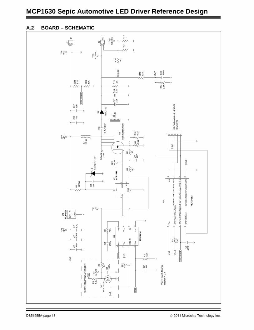
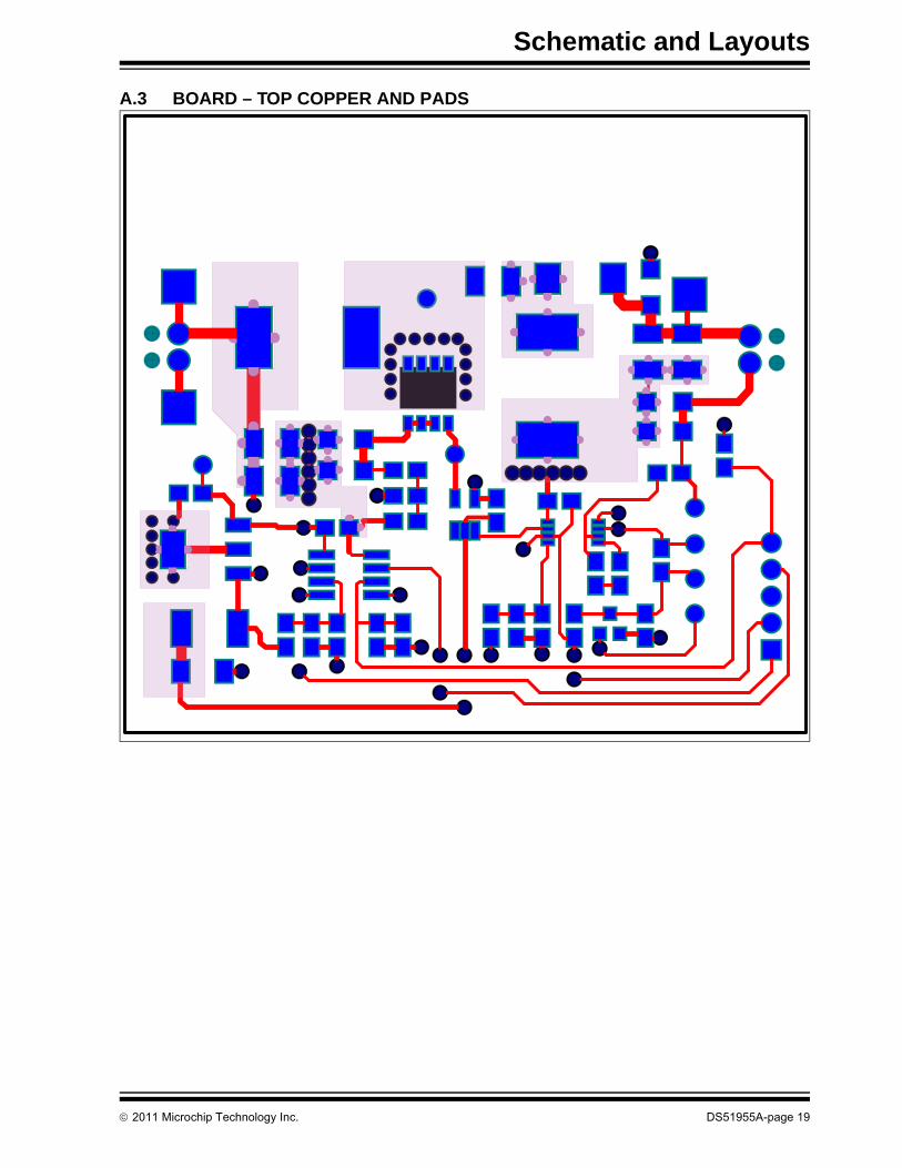
A.1 INTRODUCTIONThis appendix contains the following schematics and layouts for the MCP1630 Sepic Automotive LED Driver Reference Design User’s Guide:• Board – Schematic• Board – Top Copper and Pads• Board – Top Copper Pads and Silk• Board – Top Silk and Pads• Board – Bottom Copper and Pads
© 2011 Microchip Technology Inc. DS51955A-page 17
MCP1630 Sepic Automotive LED Driver Reference Design
A.2 BOARD – SCHEMATIC
TP4
+5V
U4
MCP1790
+5V
C3
100N
C6
100N
C7
4.7u
OU
TIN
GN
DR
6 68/1
W
TP7
VIN
+
L1 22uH
C11
10u
C12
10u
R11
91K
R12
10K
+VIN
_SE
NS
E
TP8
VIN
-J2
IN1 2
1 2
TP9
VO
UT+
J3
OU
T1 2
1 2
TP10
ISE
NS
E R18 1
R17 1
R16
10K
ISE
NS
E
R15
62K
OV
P
C15
470P
R14
3.3K
R13
15K
C14
2.2u
C13
2.2u
L2 22uH10
BQ
100
D2
C10
2.2u
/100
V
Q2
BS
C19
6N10
NS
G
R10
0.22
R9
0.22
C9 22P
R8
1K
R7
1K
TP5
DR
IVED
RA
INTP
6
MCP1416
U3
SM
AZ1
5-13
-FD
1C
81U
2
35
1
4VD
D
OU
T
NC
GN
D
IN
TP3
CS
SLO
PE
CO
MP
EN
SAT
ION
CK
T.
TP1
SLO
PE
R1
5.1K
Q1
ND
S70
02A
R2
2 K7
C1
1500
P
+5V
OS
C
TP2
OS
C+5
V
ISE
NS
E
R5
10K
C4
1500
P
U1
MCP1630
1 6 3 5
2 7 4 8
FB VIN
OS
C IN
VR
EF
Com
p
VE
XT
CS
GN
D
R3
100k
C2
1U
VR
EF
VR
EF
= lo
ut X
Rse
nse
Rse
nse
= 0.
5
+5V
C5
470P
R4
2M7
PIC12F683
U2
1 2 3 4
8 7 6 5
VR
EF
VD
D
GP
5/TI
CK
I/OS
C1/
CLK
IN
GP
4/A
N3/
OS
C2/
CLK
OU
T
GP
3/M
CLR
/VP
P
VS
S
GP
0/A
N0/
CIN
+/IC
SP
DAT
/ULP
WU
GP
1/A
N1/
CIN
-/VR
EF/
ICS
PC
LK
GP
2/A
N2/
T0C
KI/I
NT/
CO
UT/
CC
P1
+VIN
_SE
NS
E
OS
C
+5V
J1 1 2 3 4 5
PR
OG
RA
MM
ING
HE
AD
ER
DIM
MIN
G
DS51955A-page 18 © 2011 Microchip Technology Inc.
Schematic and Layouts
A.3 BOARD – TOP COPPER AND PADS
© 2011 Microchip Technology Inc. DS51955A-page 19

MCP1630 Sepic Automotive LED Driver Reference Design
A.4 BOARD – TOP COPPER PADS AND SILK
DS51955A-page 20 © 2011 Microchip Technology Inc.

Schematic and Layouts
A.5 BOARD – TOP SILK AND PADS
© 2011 Microchip Technology Inc. DS51955A-page 21

MCP1630 Sepic Automotive LED Driver Reference Design
A.6 BOARD – BOTTOM COPPER AND PADS
DS51955A-page 22 © 2011 Microchip Technology Inc.

MCP1630 SEPIC AUTOMOTIVE LEDDRIVER REFERENCE DESIGN
Appendix B. Bill of Materials (BOM)
TABLE B-1: BILL OF MATERIALS (BOM)Qty Reference Description Manufacturer Part Number
4 B1, B2, B3, B4 BUMPON HEMISPHERE .44X.20 CLEAR
3M SJ-5303 (CLEAR)
2 C1,C4 CAPACITOR 1500P 50V COG 5% SMD 0805
KEMET® C0805C152J5GACTU
1 C2 CAPACITOR 1U 16V X7R 10% SMD 0805
KEMET C0805C105K4RACTU
2 C3, C6 CAPACITOR 100N 100V X7R 10% SMD 0805
KEMET C0805C104K1RACTU
2 C5, C15 CAPACITOR 470P 50V COG 5% SMD 0805
KEMET C0805C471J5GACTU
1 C7 CAPACITOR 4.7U 10V X7R 10% SMD 0805
TAIYO YUDEN Co., Ltd. LMK212B7475KG-T
1 C8 CAPACITOR 1U 25V X7R 10% SMD 0805
KEMET C0805C105K3RACTU
1 C9 CAPACITOR 22P 50V COG 5% SMD 0805
KEMET C0805C220J5GACTU
3 C10, C13, C14 CAPACITOR 2.2U 100V X7R 10% SMD 1210
KEMET C1210C225K1R1C
2 C11, C12 CAPACITOR 10U 25V X7R 10% SMD 1210
KEMET C1210X106K3RACTU
1 D1 SMAZ15-13-F DIODE ZENNER 15V/1W SMD SMA
Diodes Incorporated® SMAZ15-13-F
1 D2 10BQ100 DIODE SCHOTTKY 100V 1A SMB
Vishay Intertechnology, Inc.
10BQ100TRPBF
1 J1 CONN HEADER 5POS .100 VERT TIN
Molex® Connector Corp. 22-03-2051
2 J2, J3 CONN TERM BLOCK 2.54MM 2POS Phoenix Contact 17256562 L1, L2 INDUCTOR POWER 22UH 6.0A
SMDWurth® Group 7443551221
1 PCB RoHS Compliant Bare PCB, MCP1630 SEPIC Automotive LED Driver Reference Design
— 104-00323
1 Q1 NDS7002A MOSFET N-CH 60V 280MA SOT-23
Fairchild Semiconductor®
NDS7002A
1 Q2 BSC196N10NS G MOSFET N-CH 100V 45A TDSON-8
Infineon Technologies AG
BSC196N10NS G
1 R1 RESISTOR 5.1K OHM 1/8W 1% SMD 0805
Vishay Intertechnology, Inc.
CRCW08055K10FKEA
1 R2 RESISTOR 2.7K OHM 1/8W 1% SMD 0805
Vishay Intertechnology, Inc.
CRCW08052K70FKEA
Note 1: The components listed in this Bill of Materials are representative of the PCB assembly. The released BOM used in manufacturing uses all RoHS-compliant components.
© 2011 Microchip Technology Inc. DS51955A-page 23

MCP1630 Sepic Automotive LED Driver Reference Design
1 R3 RESISTOR 100K OHM 1/8W 1% SMD 0805
Vishay Intertechnology, Inc.
CRCW0805100KFKEA
1 R4 RESISTOR 2.7M OHM 1/8W 1% SMD 0805
Vishay Intertechnology, Inc.
CRCW08052M70FKEA
3 R5, R12, R16 RESISTOR 10K OHM 1/8W 1% SMD 0805
Vishay Intertechnology, Inc.
CRCW080510K0FKEA
1 R6 RESISTOR 68 OHM 1W 5% SMD 2512
Vishay Intertechnology, Inc.
CRCW251268R0JNEG
2 R7, R8 RESISTOR 1K OHM 1/8W 1% SMD 0805
Vishay Intertechnology, Inc.
CRCW08051K00FKEA
2 R9, R10 RESISTOR 0.22 OHM 1/2W 1% SMD 1206
Vishay Intertechnology, Inc.
RCWE1206R220FKEA
1 R11 RESISTOR 91K OHM 1/8W 1% SMD 0805
Vishay Intertechnology, Inc.
CRCW080591K0FKEA
1 R13 RESISTOR 15K OHM 1/4W 1% SMD 1206
Vishay Intertechnology, Inc.
CRCW120615K0FKEA
1 R14 RESISTOR 3.3K OHM 1/8W 1% SMD 0805
Vishay Intertechnology, Inc.
CRCW08053K30FKEA
1 R15 RESISTOR 62K OHM 1/8W 1% SMD 0805
Vishay Intertechnology, Inc.
CRCW120615K0FKEA
2 R17, R18 RESISTOR 1 OHM 1/4W 1% SMD 1206
Vishay Intertechnology, Inc.
CRCW12061R00FKEA
3 TP7, TP8, TP9 TEST POINT PC COMPACT SMT Keystone® Electronics Corp.
5016
1 U1 MCP1630 HIGH-SPEED uC ADAPTABLE PWM CONTROLLER MSOP10
Microchip Technology Inc.
MCP1630-E/MS
1 U2 PIC12F683 8BIT FLASH MICROCONTROLLER SOIC8
Microchip Technology Inc.
PIC12F683-E/SN
1 U3 MCP1416 TINY 1.5A POWER MOSFET DRIVER SOT23-5
Microchip Technology Inc.
MCP1416T-E/OT
1 U4 MCP1790 70MA HIGH-VOLTAGE REGULATOR SOT-223
Microchip Technology Inc.
MCP1790-5002E/DB
TABLE B-1: BILL OF MATERIALS (BOM) (CONTINUED)Qty Reference Description Manufacturer Part Number
Note 1: The components listed in this Bill of Materials are representative of the PCB assembly. The released BOM used in manufacturing uses all RoHS-compliant components.
DS51955A-page 24 © 2011 Microchip Technology Inc.

MCP1630 SEPIC AUTOMOTIVE LEDDRIVER REFERENCE DESIGN
Appendix C. Firmware Flowchart
C.1 MCP1630 SEPIC AUTOMOTIVE LED DRIVER REFERENCE DESIGN FIRMWARE FLOWCHART
Start
GPIO SetupGP5 -> Vref OUTGP2 -> CLK OUTGP4 -> Vin SENSEGP1 -> OVP Input
ADC Setup
Analog Comparator Setup
PWM Setup
Vref DC = 0
Enable Interrupts
PWM = OFFSoft_Start = 1
?
Soft_Start = 1?
Soft_Start()
Soft_Start = 0
No Yes
Read Vin
Vin > Vin_minVin < Vin_max
?
FAULT = 1PWM = OFF FAULT = 1
?FAULT = 0Soft_Start()
Read Push-ButtonVref DC ++
Vref DC = 8?
Vref DC = 0
No
No
No
Yes
Yes
Yes
No
Interrupt
Comparator Tripped?
PWM = OFFFAULT = 1CMIF = 0
Timer Interrupt?
RETI
Yes
No
Generate Vref Signal PWM
TOIF = 0
No
Yes
© 2011 Microchip Technology Inc. DS51955A-page 25

MCP1630 Sepic Automotive LED Driver Reference Design
NOTES:
DS51955A-page 26 © 2011 Microchip Technology Inc.

MCP1630 SEPIC AUTOMOTIVE LEDDRIVER REFERENCE DESIGN
Appendix D. Test Points and Waveforms
D.1 TEST POINTS DESCRIPTION
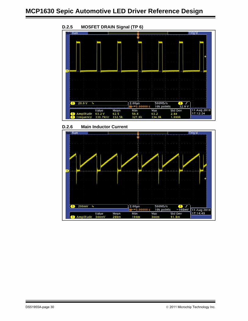
TABLE D-1: TEST POINTSTestpoint Name Description
TP1 RAMP Artificial ramp for Slope CompensationTP2 CLK Master clock for PWM controllerTP3 CS Current sense pin for PWM controllerTP4 +5V Microcontroller and PWM controller supply voltageTP5 DRIVE Gate drive of Power MOSFETTP6 DRAIN Drain terminal of the Power MOSFETTP7 +VIN Input VoltageTP8 GND Board ground. All measurements are referred to this test point.TP9 VOUT Output Voltage
TP10 ISENSE Main current sense test point. The output current is estimated by dividing the voltage from this test pint with 0.5.
© 2011 Microchip Technology Inc. DS51955A-page 27

MCP1630 Sepic Automotive LED Driver Reference Design
D.2 WAVEFORMS EXAMPLES
D.2.1 Clock Signal (TP 2)
D.2.2 Drive Signal (TP 5)
DS51955A-page 28 © 2011 Microchip Technology Inc.
Test Points and Waveforms
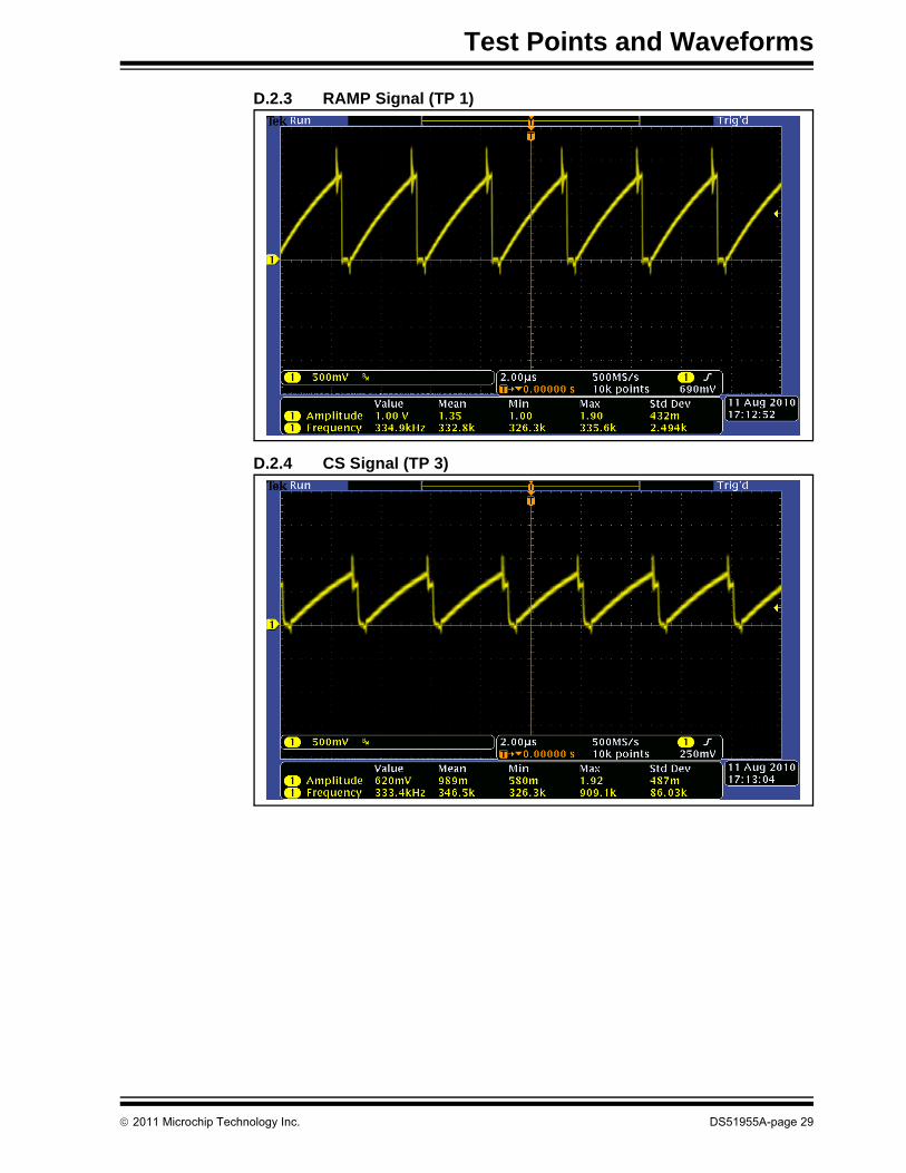
D.2.3 RAMP Signal (TP 1)
D.2.4 CS Signal (TP 3)
© 2011 Microchip Technology Inc. DS51955A-page 29
MCP1630 Sepic Automotive LED Driver Reference Design
D.2.5 MOSFET DRAIN Signal (TP 6)
D.2.6 Main Inductor Current
DS51955A-page 30 © 2011 Microchip Technology Inc.

Test Points and Waveforms
D.2.7 Typical Output Ripple/Noise of the SEPIC Converter
D.2.8 Typical Step Response (Zero to Full Load)
© 2011 Microchip Technology Inc. DS51955A-page 31

MCP1630 Sepic Automotive LED Driver Reference Design
D.2.9 Typical Efficiency vs Output Voltage
Efficiency vs. Output Voltage
72.074.076.078.080.082.084.086.0
0 10 20 30 40 50 60Output Voltage (V)
Effic
ienc
y %
eff
DS51955A-page 32 © 2011 Microchip Technology Inc.

© 2011 Microchip Technology Inc. DS51955A-page 33
NOTES:

DS51955A-page 34 © 2011 Microchip Technology Inc.
AMERICASCorporate Office2355 West Chandler Blvd.Chandler, AZ 85224-6199Tel: 480-792-7200 Fax: 480-792-7277Technical Support: http://www.microchip.com/supportWeb Address: www.microchip.comAtlantaDuluth, GA Tel: 678-957-9614 Fax: 678-957-1455BostonWestborough, MA Tel: 774-760-0087 Fax: 774-760-0088ChicagoItasca, IL Tel: 630-285-0071 Fax: 630-285-0075ClevelandIndependence, OH Tel: 216-447-0464 Fax: 216-447-0643DallasAddison, TX Tel: 972-818-7423 Fax: 972-818-2924DetroitFarmington Hills, MI Tel: 248-538-2250Fax: 248-538-2260IndianapolisNoblesville, IN Tel: 317-773-8323Fax: 317-773-5453Los AngelesMission Viejo, CA Tel: 949-462-9523 Fax: 949-462-9608Santa ClaraSanta Clara, CA Tel: 408-961-6444Fax: 408-961-6445TorontoMississauga, Ontario, CanadaTel: 905-673-0699 Fax: 905-673-6509
ASIA/PACIFICAsia Pacific OfficeSuites 3707-14, 37th FloorTower 6, The GatewayHarbour City, KowloonHong KongTel: 852-2401-1200Fax: 852-2401-3431Australia - SydneyTel: 61-2-9868-6733Fax: 61-2-9868-6755China - BeijingTel: 86-10-8569-7000 Fax: 86-10-8528-2104China - ChengduTel: 86-28-8665-5511Fax: 86-28-8665-7889China - ChongqingTel: 86-23-8980-9588Fax: 86-23-8980-9500China - HangzhouTel: 86-571-2819-3187 Fax: 86-571-2819-3189China - Hong Kong SARTel: 852-2401-1200 Fax: 852-2401-3431China - NanjingTel: 86-25-8473-2460Fax: 86-25-8473-2470China - QingdaoTel: 86-532-8502-7355Fax: 86-532-8502-7205China - ShanghaiTel: 86-21-5407-5533 Fax: 86-21-5407-5066China - ShenyangTel: 86-24-2334-2829Fax: 86-24-2334-2393China - ShenzhenTel: 86-755-8203-2660 Fax: 86-755-8203-1760China - WuhanTel: 86-27-5980-5300Fax: 86-27-5980-5118China - XianTel: 86-29-8833-7252Fax: 86-29-8833-7256China - XiamenTel: 86-592-2388138 Fax: 86-592-2388130China - ZhuhaiTel: 86-756-3210040 Fax: 86-756-3210049
ASIA/PACIFICIndia - BangaloreTel: 91-80-3090-4444 Fax: 91-80-3090-4123India - New DelhiTel: 91-11-4160-8631Fax: 91-11-4160-8632India - PuneTel: 91-20-2566-1512Fax: 91-20-2566-1513Japan - YokohamaTel: 81-45-471- 6166 Fax: 81-45-471-6122Korea - DaeguTel: 82-53-744-4301Fax: 82-53-744-4302Korea - SeoulTel: 82-2-554-7200Fax: 82-2-558-5932 or 82-2-558-5934Malaysia - Kuala LumpurTel: 60-3-6201-9857Fax: 60-3-6201-9859Malaysia - PenangTel: 60-4-227-8870Fax: 60-4-227-4068Philippines - ManilaTel: 63-2-634-9065Fax: 63-2-634-9069SingaporeTel: 65-6334-8870Fax: 65-6334-8850Taiwan - Hsin ChuTel: 886-3-5778-366Fax: 886-3-5770-955Taiwan - KaohsiungTel: 886-7-536-4818Fax: 886-7-330-9305Taiwan - TaipeiTel: 886-2-2500-6610 Fax: 886-2-2508-0102Thailand - BangkokTel: 66-2-694-1351Fax: 66-2-694-1350
EUROPEAustria - WelsTel: 43-7242-2244-39Fax: 43-7242-2244-393Denmark - CopenhagenTel: 45-4450-2828 Fax: 45-4485-2829France - ParisTel: 33-1-69-53-63-20 Fax: 33-1-69-30-90-79Germany - MunichTel: 49-89-627-144-0 Fax: 49-89-627-144-44Italy - Milan Tel: 39-0331-742611 Fax: 39-0331-466781Netherlands - DrunenTel: 31-416-690399 Fax: 31-416-690340Spain - MadridTel: 34-91-708-08-90Fax: 34-91-708-08-91UK - WokinghamTel: 44-118-921-5869Fax: 44-118-921-5820
Worldwide Sales and Service
08/02/11