mcna certification report (cdrl a047) - nasa certification report (cdrl a047) ... other types of...
TRANSCRIPT

Certification Report D794-10185-1RevNEW.doc-6/13/2005 1:57:00 PM
MCNA Certification Report
(CDRL A047)
DOCUMENT NUMBER: RELEASE/REVISION: RELEASE/REVISION DATE:
D794-10185-1 Rev NEW 6/10/2005
CONTENT OWNER:
Phantom Works- ANCO (9S-7S-73CN)
All future revisions to this document must be approved by the content owner before release.
Export Compliance NoticeThis document has been reviewed and approved for release to ALL by Export Compliance. Log ID: PW-05-038 Review Date: 06/13/2005Additional questions should be addressed to your designated Boeing Export Compliance Administrator.
Ruth Garcia 206-655-4503
Rev NEW D794-10185-1 ii
Document Information Document Type
Contract Deliverable Original Release Date
June10th, 2005 Contract Number (if required)
XX Preparing Organization (if different from owning organization)
XX Hardware and Software Used
IBM PC Microsoft Word Location of Software Files (optional)
EVS Boeing Web URL (optional)
https://atmevs.web.boeing.com/atm/evs/default.asp Notes and Limitations (optional)
Signatures for original release
AUTHOR: Al Sipe
Sign and type: First Name MI Last Name Org. Number
Date
APPROVAL: John W. Moore
Sign and type: First Name MI Last Name Org. Number
Date
DOCUMENT RELEASE:
Org. Number
Date
Copyright © 2000 The Boeing Company
Rev NEW D794-10185-1 iii
Table of Contents
1 INTRODUCTION ...............................................................................................................1 1.1 Purpose ...................................................................................................................1 1.2 Scope ......................................................................................................................1 1.3 Document Organization .........................................................................................1 1.4 Honeywell Effort ....................................................................................................2
2 Baseline Certification/Approval Process .............................................................................3 2.1 Communication System Approval .........................................................................3
2.1.1 Safety Services ..............................................................................................4 2.1.2 ACARS..........................................................................................................6 2.1.3 Inmarsat Aero H SATCOM ..........................................................................6 2.1.4 The DO-270 process......................................................................................7
2.2 Avionics Approval and Certification .....................................................................7 2.3 Aircraft Approval and Certification .......................................................................9 2.4 Software Certification Issues................................................................................12 2.5 Summary of RTCA DO-296 ................................................................................13
3 Visionary Approval/Certification Process .........................................................................15 3.1 System Approval ..................................................................................................15 3.2 Avionics Approval and Certification ...................................................................16 3.3 Aircraft Approval and Certification .....................................................................16 3.4 Software Approval and Certification ...................................................................16
4 Challenges for Approval/Certification...............................................................................18 4.1 Challenges for System Approval..........................................................................18
4.1.1 FAA Process for System Approval .............................................................18 4.1.2 MASPS Technique-specific Documentation...............................................18 4.1.3 Aeronautical CNS/ATM Spectrum Issues .................................................19 4.1.4 Reliance on Commercial Software..............................................................20 4.1.5 Treatment of Commercial Quality of Service Provisions ...........................20 4.1.6 System/Service Provider Participation........................................................20 4.1.7 High Layer Integrity Issues .........................................................................21
4.2 Challenges for Avionics Approval .......................................................................21 4.2.1 MOPS Technique-specific Appendices.......................................................21 4.2.2 Reliance on Commercial Software..............................................................21
4.3 Challenges Aircraft Approval ..............................................................................22 4.3.1 Well-defined and Meaningful RCP Standards ............................................22 4.3.2 Cabin/Cockpit Isolation Issues....................................................................22
5 CONCLUSIONS & RECOMMENDATIONS..................................................................23 5.1 System Approval ..................................................................................................23

Rev NEW D794-10185-1 iv
5.2 Avionics Approval and Certification ...................................................................23 5.3 Aircraft Approval and Certification .....................................................................24
6 ACRONYMS.....................................................................................................................25
7 References..........................................................................................................................27
Rev NEW D794-10185-1 v
List of Figures Figure 1 TSO Preparation Process ..................................................................................8 Figure 2 Location FAA Aircraft Certification Offices .................................................12 Figure 3 Summary of ITU Spectrum Allocation Process .............................................19

Rev NEW D794-10185-1 vi
List of Tables Table 1 Summary of Aircraft/Engine/Propeller Approval Types [8] ...........................10
Rev NEW D794-10185-1 1
1.1 Purpose
The goal of the MCNA effort is to develop an integrated systems-of-systems approach and technology development roadmap that will provide guidance for ongoing and planned NASA Glenn Research Center (GRC) and FAA research activities including Advanced CNS Architectures and System Technologies (ACAST) and Transforming the NAS (TNAS). Certification is constantly cited as one of the key aspects avionics development, and, therefore is a key aspect of MCNA as well. To promote further insight into the certification process and other aspects of avionics development that are critical in the reduction of avionics costs, this report describes the avionics and systems certification processes
1.2 Scope
The scope of this report includes discussions of the following items
1. Aspects of the proposed MCNA architecture that will affect avionics certification considerations.
2. Avionics technologies (such as software defined radio) that will have significant positive or negative impacts on the certification process or that will significantly reduce the overall cost of avionics ownership.
3. Certification or approval of communications systems for use in conveying safety-related information between ground and airborne users and, potentially, among airborne users operating in ad-hoc networks.
In this report, the term "certification" is used in the broadest possible sense; it includes the full
range of approval activities, including functional approval of the avionics, issuing of an operating certificate for aircraft, and acceptance/approval of the communication system for MCNA-appropriate communications. This last issue is a thorny one, as there are specific requirements that have historically been applied to or associated with the provision of aeronautical safety related communications. As the study has progressed, it has become obvious that this "service certification" factor is equally important to those "avionics certification" factors listed above. Therefore, this report includes a discussion of service approval, in addition to avionics-specific issues. Furthermore, our consideration of certification includes the development of industry standards or other documentation upon which the FAA approvals and certification activities can be based.
1.3 Document Organization
This document is organized into five sections. Section 2 discusses the current process for approving and certifying elements of an aeronautical communications network. Section 3 presents a visionary end state for a future certification process. Section 4 identifies and discusses
1 INTRODUCTION
Rev NEW D794-10185-1 2
barriers to achieving the visionary end state. Section 5 provides an overall summary, lists conclusions, and suggestions for future MCNA-related work
1.4 Honeywell Effort
Items 1 and 2 listed in Section 1.2 are required by the Honeywell's MCNA Statement of Work. Item 3, which encompasses a significant portion of this document, is included based on issues developed during performance of the MCNA Certification task.
Rev NEW D794-10185-1 3
This section discusses the current (as of mid 2005) processes for "certification" and approval of communication systems, avionics, and aircraft. As noted in the introduction, this report uses the term "certification" in the broadest possible context, including all approvals, certificates, and other types of formal documents that allow an aeronautical communication system and its associated avionics to provide communication services to appropriately equipped aircraft.
Before discussing the individual system, avionics, and aircraft processes, it is useful to note that the certification process is driven by the intended function of the information carried over the system. In the case where the communications is not considered either essential or critical to aircraft operation, the criteria are quite simple: 1) does the entity perform its intended function, and, 2) does it interfere with other systems on the aircraft? If the answer to the first question is "Yes" and to the second question is "No", then operating approvals are relatively straightforward. In any other combination of answers, operating approval will be denied. If, however, communications – or, more precisely, the communication services being offered – are essential or critical to the aircraft operation, then the processes in all cases are more complex. The complexity builds upon the two fundamental questions, which must be answered in all cases.
The implication for MCNA is this. If the services offered are useful to the pilots, but are neither essential nor critical to aircraft operation, existing standards for certification and approval are easily met. It may be the case for MCNA and SWIM that the same data used for essential or critical services may also be used for other SWIM services. In this case, it is generally true that the critical nature of the data is a function of its integrity and its timeliness. It is possible that applications that do not require either of these properties may be approved under the less restrictive non-essential guidelines.
2.1 Communication System Approval
There is currently (mid 2005) no standard process for approval of a new communications system for any level of service beyond non-essential. Information and data that might form the inputs to such a process for "route", i.e., "safety", services, are contained in RTCA DO-270 Minimum Aviation System Performance Standards for Aeronautical Mobile Satellite (Route) Services (AMS(R)S) [1], but there is as yet no FAA process for accepting such data or "approving" such a service. There are, however, two examples of quasi-commercial systems that have been approved for use in aeronautical safety communications: the Aircraft Addressing and Reporting System (ACARS) and the Inmarsat Aero H/I/H+ family of satellite communication services. The following sub-paragraphs first discuss the two categories of safety services, including examples of messages from each category, then summarize ACARS and Aero H services and their approval process, and finally summarize the process described in DO-270.
In contrast to system approval, the processes for approving and certifying avionics and aircraft for all types of communication, navigation, and surveillance systems are well known.
2 Baseline Certification/Approval Process
Rev NEW D794-10185-1 4
2.1.1 Safety Services The certification process (in the broad sense) differs for safety and non-safety services, so it is
useful to define what is meant. A comprehensive, albeit somewhat dated, set of definitions is given in RTCA DO-215A [2]. In DO-215A, safety services are subdivided into Air Traffic Services (ATS) and Aeronautical Operational Control (AOC) services
2.1.1.1 Air Traffic Services (ATS)
Air Traffic Services (ATS) include Air Traffic Control (ATC), the Flight Information Service (FIS) and the Alerting Service. Within the U.S.A., the long-term plan is that ATC services will use the FAA Host Computer at the ARTCCs and eventually the Advanced Automation System (AAS) with its Area Control Computer Complex (ACCC) and its Automated En-Route Air Traffic Control (AERA) software as well as Tower Control Computer Complexes (TCCC).
DO-215A provides the following list of Air Traffic Control applications anticipated to be supported by data links:
1. Assignment/confirmation of assigned altitude
2. Automated airspace alert
3. Clearance delivery
4. Designated traffic report
5. En-route metering advisory
6. In-flight filing of flight plan and flight plan amendments
7. Minimum safe altitude
8. Predeparture clearance delivery
9. Transfer of communications
10. Frequency change
11. Aircraft estimated trajectory
12. Aircraft estimated trajectory (FMC/AERA exchange)
13. Arrival identification and state
14. Tactical maneuver (FMC/AERA exchange)
15. TCAS/AERO interface message
16. Trial plan probe
Rev NEW D794-10185-1 5
17. Visual flight rules flight plan activation/following
18. Local landing clearance
19. Sequence to land
20. Situation alerts
a. ATC contact alert
b. Automatic, ground initiated hazardous weather
c. Emergency landing vectors
d. In-flight emergency; safety
e. Military interception procedures
f. Out of conformance check
g. TCAS sensitivity
h. VFR terminal area (including ARSA) access
i. Hijack indication
j. In-flight emergency; medical
2.1.1.2 Aeronautical Operational Control
Like ATS, Aeronautical Operational Control (AOC) is a safety service defined in ICAO Annex 6, Part I, which gives the right and duty to exercise authority over the initiation, continuation, diversion or termination of a flight in the interest of the safety of aircraft, and the regularity and efficiency of flight functions may directly accommodate dispatch and flight operations department functions, or may interface with other departments such as Engineering, Maintenance and Scheduling, in exercising or coordinating related functions. DO-215A provides the following list of AOC functions:
1. Exceptional situation handling (aircraft/flight emergencies, hijack, etc.)
2. Flight planning
3. Weather information
4. Airports/airways operational information (NOTAMS), etc.
5. Movement control (flight departure, arrival, delay and diversion)
6. Cockpit crew flight times/scheduling

Rev NEW D794-10185-1 6
7. Aircraft engine monitoring
8. In-flight maintenance problem reporting and solving
9. Fuel consumption and requirements
10. Aircraft scheduling (for particular flights)
11. Schedule modifications (changes or cancellation of flights), etc.
These AOC functions operate via air-ground voice and data communications either through the cockpit crew or directly with airborne sensors or systems; e.g., Flight Management Systems (FMS), Digital Flight Data Acquisition Units (DFDAU). Functions served would include FMS Operational Data Base update on flight plans, load and balance, weather, pre-departure clearances, etc.; and DFDAU recording of and reporting on engine health monitoring, fuel flow/status requirements, etc.
2.1.2 ACARS ACARS was developed in the mid-1970s as a low-bandwidth digital communication overlay
on conventional double-sideband amplitude modulated (DSB-AM) voice channels for the purpose of providing "out-off-on-in"1 aircraft status in near real time. When initially approved ACARS was intended only for communicating non-essential data that was informative to the airline and aircrew, but not essential for safe operation of the aircraft. Over the intervening decades use of the system has expanded to High Frequency Data Link (HFDL) and SATCOM data channels. The use of legacy ACARS with more modern, high bandwidth data links (e.g. ACARS-over-AVLC or AOA) has dramatically increased, and now includes a number of AOC and ATS services, despite the fact that ACARS was initially approved only for non-safety applications. This lead to FAA concerns, which, in turn, lead to the formation of RTCA SC-201. A summary of the key findings of SC-201 is contained in Section 2.5 below.
2.1.3 Inmarsat Aero H SATCOM Inmarsat Aero H SATCOM has also been approved for AOC and some ATS services,
specifically as part of the Future Air Navigation System (FANS) program in Pacific Ocean airspace. For the Aero H service, guidance on the use of data and voice services were developed in the RTCA community [2, 3], as were the Minimum Operational Performance Standards (MOPS) for the avionics [4]. ICAO Standards and Recommended Practices (SARPs) were developed by the Aeronautical Mobile Communications Panel, approved by the Air Navigation Commission, and published as part of Annex 10 to the International Convention on Civil Aviation [5, Volume III Part I Digital Communication Systems].
The Inmarsat example illustrates the regulatory document portion of what might become a standard process. First, the community develops Minimum Aviation System Performance
1 Out of the gate, off of the runway, on the runway, into the gate.

Rev NEW D794-10185-1 7
Standards for the system as a whole (DO-215A and DO-222 fit the bill for Inmarsat). Then MOPS for the avionics are developed. ICAO documentation preparation usually occurs in parallel with this process.2
Comparison of Aero H with ACARS illustrates a difference between a service that shares resources with commercial service (Aero H) and a service (ACARS) that is dedicated to aeronautical use. Mechanisms to assure priority, precedence and, if necessary, preemption of system resources for the safety-related (AOC and ATS and related voice traffic) are built into the standards for Aero H. ACARS, AOA, and VDL Mode 2 are services dedicated to aeronautical service, and do not have inherent priority mechanisms at the media access or link layers of the protocol stack.
2.1.4 The DO-270 process RTCA Special Committee 165 recognized a need for a generic process that could be
customized for variety of specific commercial satellite communication alternatives, possibly including advanced Inmarsat services. DO-270 [1] captures requirements in a generic form. Rather than dictate specific requirements for any new service, DO-270 instead provides a series of templates for what information a system/service provider must provide. In addition, DO-270 provides specific rules for how various analyses documenting the communication performance of any proposed system must be conducted. The purpose of these rules and pro forma declarations is to assure a common baseline set of descriptions of the service and system characteristics.
DO-270 is deliberately vague regarding which organization receives, reviews and approves the system-specific data. Therefore, although the documentation requirements are well established, the process from the completion of the data through the approval of the system or service for safety applications is not defined. Because the process is not defined the time duration can not be estimated.
Strictly speaking, DO-270 refers only to next generation satellite systems, although the process could be logically extended to air-to-ground communications in general.
2.2 Avionics Approval and Certification
The functional requirements of the avionics are generally specified in a Minimum Operational Performance Standard (MOPS). The RTCA MOPS document development processes is illustrated in Figure 1.3 Once the Special Committee has been established, the document
2 In an ideal systems engineering environment, SARPs would be created and approved before MASPS, which, in
turn, would be completed before MOPS, as SARPs define requirements that all ICAO countries should abide by. RTCA documents are specific to US and should be a subset or extension of ICAO requirements. ICAO documents also tend to take an end-to-end systems/services view which is usually lacking in RTCA MOPS documents. However, as a practical matter, development of SARPs, MASPS and MOPS tends to occur in parallel. In the past, this has lead to some inefficiencies, as the early versions of the documents are not always consistent.
3 Figure 1 illustrates the MOPS process, as this is the process that affects the TSO. As noted in the previous

Rev NEW D794-10185-1 8
development, preparation, review, and approval process can take 24 to 36 months. The MOPS development process can be as short as 15 months, but such an accelerated schedule requires an extraordinary amount of FAA involvement in the document preparation.
When complete, the MOPS can then be referenced in an FAA Advisory Circular (AC). While it is possible to skip the MOPS process and proceed directly to the Advisory Circular, this approach results in an AC that must contain the functional requirements and the method of verification within the AC itself. This requires at least as much effort as the MOPS process, and results in a complicated AC that faces a tougher review process within the FAA. The result of the AC is a Technical Standard Order (TSO).
PMC approves
SC
SC writesMOPS
SC approves
MOPS
PMCapproves
MOPS
FAADevelops
TSO
PublicReview
TSOpublished
15 months < t < 36 monthsTypical 24 months
22 months < t < 96 monthsTypical 36 months
AC (FAA) Advisory CircularFAA Federal Aviation AdministrationMOP Minimum Operational Performance StandardsPMC Program Management Committee of RTCASC Special CommitteeWG Working Group
Figure 1 TSO Preparation Process
Some believe that a TSO is required before equipment can be installed on an aircraft. While it is true that a TSO simplifies the manufacturing, marketing of avionics, and the approval of the installation by means of a Supplemental Type Certificate (STC), and granting of operational authorization, a TSO is not a requirement. Avionics can be, and frequently are, approved for installation and use in both safety and non-safety applications on the basis of a Parts Manufacturer Approval (PMA). In fact, thousands of SATCOM installations, including those used for FANS 1A installations, have been completed and approved by means of a PMA without the benefit of the recently published TSO-C132 [6].
In parallel with the development of DO-270 [1], SC-165 also completed a generic MOPS for next generation satellite systems. This MOPS was published as DO-262[7]. Like the DO-270 MASPS, it is generic in nature, and discusses what data must be presented and how the analysis must be performed. Like the MASPS, it requires preparation of a technique-specific appendix. Like the MASPS, the destination and process for approval of this appendix is intentionally vague. Finally, like the MASPS, the DO-262 document could be used as a template for other "next generation" non-SATCOM air-to-ground links.
footnote, SARPs, MASPS and MOPS development often occurs in parallel.
Rev NEW D794-10185-1 9
2.3 Aircraft Approval and Certification
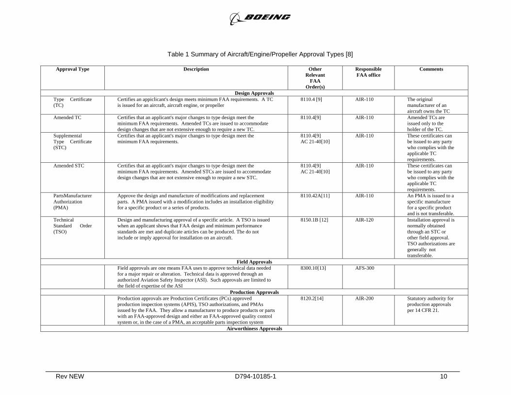
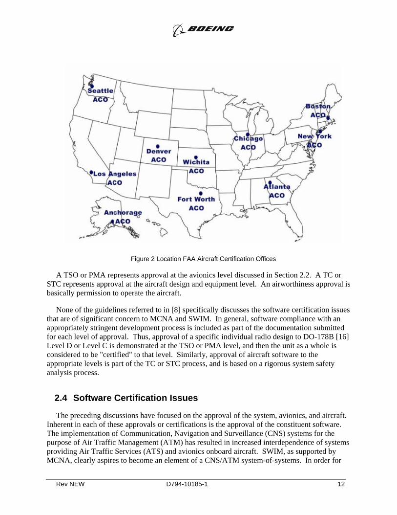
The approval of an individual aircraft or set of aircraft for operation in obtained by means of a Type Certificate (TC) or Supplemental Type Certificate (STC) obtained from the regional FAA Aircraft Certification Office (ACO) (see Figure 2). The various types of approval and certification are described in FAA Order 8100.5A [8]. Table 1 summarizes the various types of FAA approval and certification described in [8], along with references to the other FAA orders and cognizant FAA organizations responsible for the various approvals.
Rev NEW D794-10185-1 10
Table 1 Summary of Aircraft/Engine/Propeller Approval Types [8]
Approval Type Description Other Relevant
FAA Order(s)
Responsible FAA office
Comments
Design Approvals Type Certificate (TC)
Certifies an appiclicant's design meets minimum FAA requirements. A TC is issued for an aircraft, aircraft engine, or propeller
8110.4 [9] AIR-110 The original manufacturer of an aircraft owns the TC
Amended TC Certifies that an applicant's major changes to type design meet the minimum FAA requirements. Amended TCs are issued to accommodate design changes that are not extensive enough to require a new TC.
8110.4[9] AIR-110 Amended TCs are issued only to the holder of the TC.
Supplemental Type Certificate (STC)
Certifies that an applicant's major changes to type design meet the minimum FAA requirements.
8110.4[9] AC 21-40[10]
AIR-110 These certificates can be issued to any party who complies with the applicable TC requirements.
Amended STC Certifies that an applicant's major changes to type design meet the minimum FAA requirements. Amended STCs are issued to accommodate design changes that are not extensive enough to require a new STC.
8110.4[9] AC 21-40[10]
AIR-110 These certificates can be issued to any party who complies with the applicable TC requirements.
PartsManufacturer Authorization (PMA)
Approve the design and manufacture of modifications and replacement parts. A PMA issued with a modification includes an installation eligibility for a specific product or a series of products.
8110.42A[11] AIR-110 An PMA is issued to a specific manufacture for a specific product and is not transferable.
Technical Standard Order (TSO)
Design and manufacturing approval of a specific article. A TSO is issued when an applicant shows that FAA design and minimum performance standards are met and duplicate articles can be produced. The do not include or imply approval for installation on an aircraft.
8150.1B [12] AIR-120 Installation approval is normally obtained through an STC or other field approval. TSO authorizations are generally not transferable.
Field Approvals Field approvals are one means FAA uses to approve technical data needed
for a major repair or alteration. Technical data is approved through an authorized Aviation Safety Inspector (ASI). Such approvals are limited to the field of expertise of the ASI
8300.10[13] AFS-300
Production Approvals Production approvals are Production Certificates (PCs) approved
production inspection systems (APIS), TSO authorizations, and PMAs issued by the FAA. They allow a manufacturer to produce products or parts with an FAA-approved design and either an FAA-approved quality control system or, in the case of a PMA, an acceptable parts inspection system
8120.2[14] AIR-200 Statutory authority for production approvals per 14 CFR 21.
Airworthiness Approvals

Rev NEW D794-10185-1 11
Approval Type Description Other Relevant
FAA Order(s)
Responsible FAA office
Comments
Standard Certificate
An approval of an individual aircraft (Airworthiness Certificate), or an engine, propeller, TSO article or approved parts (Authorized Release Certificates). A standard certificate is issued when the aircraft is in condition for safe operation and conforms to an FAA-approved type of design
8120.2[14] 8130.21[15]
AIR-200
Special Certificate An approval of an individual aircraft (Airworthiness Certificate), or an engine, propeller, TSO article or approved parts (Authorized Release Certificates). A special certificate is issued when the aircraft does not meet the requirements for a standard airworthiness certificate, but is in condition for safe operation.
8120.2[14] 8130.21[15]
AIR-200
Rev NEW D794-10185-1 12
Figure 2 Location FAA Aircraft Certification Offices
A TSO or PMA represents approval at the avionics level discussed in Section 2.2. A TC or STC represents approval at the aircraft design and equipment level. An airworthiness approval is basically permission to operate the aircraft.
None of the guidelines referred to in [8] specifically discusses the software certification issues that are of significant concern to MCNA and SWIM. In general, software compliance with an appropriately stringent development process is included as part of the documentation submitted for each level of approval. Thus, approval of a specific individual radio design to DO-178B [16] Level D or Level C is demonstrated at the TSO or PMA level, and then the unit as a whole is considered to be "certified" to that level. Similarly, approval of aircraft software to the appropriate levels is part of the TC or STC process, and is based on a rigorous system safety analysis process.
2.4 Software Certification Issues
The preceding discussions have focused on the approval of the system, avionics, and aircraft. Inherent in each of these approvals or certifications is the approval of the constituent software. The implementation of Communication, Navigation and Surveillance (CNS) systems for the purpose of Air Traffic Management (ATM) has resulted in increased interdependence of systems providing Air Traffic Services (ATS) and avionics onboard aircraft. SWIM, as supported by MCNA, clearly aspires to become an element of a CNS/ATM system-of-systems. In order for
Rev NEW D794-10185-1 13
these systems, most of which are software-intensive, to perform their intended function while providing an acceptable level of safety, there is a need to define consistent means of providing integrity assurance for the software in these systems. Closely related guidelines for the development of software used in avionics and CNS/ATM systems are contained in RTCA DO-178B [16] and RTCA DO-278 [17], respectively.
RTCA DO-178B [16] provides guidelines for the production of software for airborne systems and equipment that performs its intended function with a level of confidence in safety that complies with airworthiness requirements. The guidelines are in the form of objectives for the software life cycle processes, descriptions of the activities and design considerations for achieving those objectives, and descriptions of the events that indicate that the objectives have been satisfied. DO-178B specifically does not address the operational aspects of the resulting software. In particular, the certification aspects of user-modifiable data are beyond the scope of DO-178B. [16, Section 1.2] RTCA DO-248B [18] contains additional interpretive material regarding the application of DO-178B.4 The additional DO-248B material is based on the experience of equipment and airframe manufacturers with the DO-178B process.
RTCA DO-278 [17] provides guidelines for the assurance of software contained in non-airborne CNS/ATM systems. The document is intended as an interpretive guide for the application of DO-178B to non-airborne CNS/ATM systems. The DO-278 guidance applies to software contained in CNS/ATM systems used in ground- or space-based applications shown by a system safety assessment process to affect the safety of aircraft occupants or airframe in its operational environment. The assurance of software resident within the aircraft boundaries, including CNS/ATM-related equipment, falls in the scope of DO-178B.
In current practice, the certification or approval of software is an integral element of the avionics and aircraft approval processes just discussed. That is, there is no software approval process independent of the TSO/PMA or TC/STC processes. In current practice, only limited approval ground- or space-based software is required, although the availability of DO-278 is changing this practice.
RTCA SC-205 is currently (mid 2005) in the process of modifying DO-178B to account for several issues raised by modern software engineering processes, including increased reuse of software (including commercial software), and increased use of model based testing.
2.5 Summary of RTCA DO-296
As noted earlier, in Section 2.1.2, ACARS was initially approved for use on the basis of non-interference with other CNS systems and "no-hazard" implications of the data carried on the ACARS data link. Over the years, however, it has become common practice to transmit an increasing amount of true AOC data and even some ATS data over the ACARS link. The ultimate applications of this data raised questions about the "no-hazard" assumption on which the ACARS approval was based. To address these concerns, FAA requested RTCA to form a
4 For the remainder of this document, all references to DO-178B should be considered to include an implicit
reference to the interpretive material of DO-248B, as well.

Rev NEW D794-10185-1 14
committee which became SC-201 to look into the issues involved with communicating information whose delay, loss, misdirection, or corruption could affect aircraft safety. Recommendations from SC-201 are documented in RTCA DO-296, [19]. The guidance in DO-296 therefore provides useful background on what processes and procedures might reasonably be expected of similar datalink services, such as those to be offered by MCNA.
DO-296 explicitly limits its consideration to messages whose delay, loss, misdirection, or corruption could lead to a hazard category major hazard or lower. The document identifies two means of addressing the issue of AOC messages whose failure or malfunction could contribute to a major hazard: design assurance and risk reduction strategies. Complying with the design assurance means developing the datalink software to DO-178B, Level C or higher. If this is done, DO-296 does not require further mitigation of major hazards. Unfortunately, the level of effort (and therefore expense) necessary for verification of Level C design assurance is significantly above that available for normal, commercial off-the-shelf software (Level E). DO-296 also permits architectural and procedural risk reduction strategies. Architectural strategies are design decisions made to mitigate a specified hazard. Examples include use of error detection, such as a cyclic redundancy check or checksum, and alphanumeric callout, where the information is transmitted in both binary and alphanumeric form and compared in the avionics. Procedural strategies include independent verification by the flight crew and transmission of multiple copies of the messages.
As noted earlier, ACARS is a dedicated aeronautical service. As such, the complicated issues of priority, precedence and preemption are not discussed in DO-296. This is in stark contrast to the emphasis in the Aero H standards [4, 5]. Although not explicitly stated in DO-296, the likely conclusion is that for dedicated aeronautical communications links, priority can be handled at the network layer or higher. Total overall mean transfer delay is then a Required Communications Performance (RCP) matter that might limit the ultimate application of the data link messages.
DO-296 is a new document, and it is not yet extensively referenced in FAA advisory circulars. It is likely to form the basis for future approval of a wide range of datalink applications, including SWIM-enabled applications transmitted over MCNA.
Rev NEW D794-10185-1 15
3.1 System Approval
As noted in Section 2.1, there is no formalized process comparable to the TSO/PMA or TC/STC process for the approval of systems in general.5 The most appropriate model for system approval may be the TC/STC process. If the FAA were to adopt a System/Service Type Certificate (SSTC or S2TC) or a Supplemental System/Service Type Certificate (SSSTC or S3TC) process that was analogous to the TC/STC process, then we might expect that the avionics and aircraft approval processes could potentially remain essentially unchanged.
Therefore, for the purpose of this report, the visionary system/service approval process is analogous to the TC/STC process described in Section 2.3. A system/service provider will submit information nominally equivalent to the scope, detail and presentation required by DO-270, regardless of whether the system is satellite- or terrestrial-based. When FAA has completed an appropriate due diligence review of the system design and implementation, the system will be issued a System/Service Type Certificate (S2TC). This certificate will indicate that the system has been approved for CNS functionality as described in the submitted documentation. The S2TC will be held by the system/service provider. In the case of satellite systems, the holder would be the satellite system operator. In the case of terrestrial systems, the holder would be owner/operator of the terrestrial infrastructure6.
Changes to the system design of any system for which an S2TC had been granted would be determined by the magnitude and complexity of the changes. Minor changes, i.e., those that did not significantly affect the key delay, integrity, availability or continuity parameters or significantly alter the system elements, including interfaces, described in the S2TC document, could be approved under a method acceptable to the FAA Administrator. Major changes, i.e., all changes not considered minor in nature, would require submission and approval of significant documentation regarding the change. This documentation, although limited to the scope of the change, could comparable in detail to that submitted with the original S2TC application. Approval of the major change would result in a Supplemental System/Service Technical Certificate (S3TC). The FAA would then be responsible for distributing information about the scope and effect of such changes using normal FAA channels. Portions of the following description are modified from [20].
5 This may be because the system design and thus, the system approval, virtually all existing aeronautical
communication, navigation and surveillance (CNS) systems has been done by the FAA or equivalent body. Thus, fielding of the system is itself an acceptance that the system design is sufficient for its intended purpose. Notable exceptions to this are ACARS and Aero H SATCOM, as noted earlier in this document. Both of these are commercial systems.
6 Note that an S2TC process has not been necessary in the past, as the FAA itself has been responsible for both the system design and the ground station operation of communications (e.g., DSB-AM), navigation (e.g., ILS, MLS), and surveillance (e.g. SSR, Mode S) ground infrastructure.
3 Visionary Approval/Certification Process
Rev NEW D794-10185-1 16
3.2 Avionics Approval and Certification
Under the visionary system approval process just discussed, avionics certification would be performed using the existing process. It is not certain that the development of a TSO would be cost- or time-effective in the visionary process. Given the multi-year timeframe for TSO development and approval,7 avionics manufacturers may choose to proceed along a PMA-based process for obvious time-to-market reasons. As noted in Table 1, both TSO and PMA approaches are perfectly acceptable for TC/STC. Under the assumption that the S2TC/S3TC system approval process would be analogous to the current TC/STC process, it is reasonable to assume that either TSO or PMA would also be acceptable for the visionary system.
If a TSO were desired, however, the visionary avionics approval process could create the equivalent of a MOPS for an S2TC or S3TC system by creating a technique-specific appendix along the guidelines of DO-262 [7]. This information could then form the basis for a TSO.
3.3 Aircraft Approval and Certification
In the visionary process, the TC/STC process would not change. The S2TC/S3TC-approved system and TSO/PMA-approved avionics would become normal elements of the process, as with any other systems and avionics. The system safety analyses would then be based on the TSO/PMA performance of the avionics and the S2TC/S3TC performance of the system. Once again, good systems engineering practice would dictate that an S2TC/S3TC be obtained before the documentation supporting a TSO/PMA was developed, and that a TSO/PMA would precede final aircraft approval certification. This strict sequence is not followed in current practice and, while desirable, does not seem to be a prerequisite for a workable future solution.
3.4 Software Approval and Certification
In the visionary software approval process, elements of SWIM/MCNA that are built upon mature commercial software can be granted certification credit based on demonstrated performance levels. In current practice, this is frequently not an option with aeronautical software, as "demonstrated performance" is seldom sufficient for the very high integrity required for DO-178 Level C software and above. It is conceivable, however, that elements of SWIM/MCNA will be built on commercial telecommunications software with potentially tens or even hundreds of millions of effective operating hours in equivalent environments.8 One barrier to such an approach is the detailed record-keeping necessary to assure that faults detected during extended operational use are tracked and closed. This record-keeping may be beyond the scope of that currently provided in the commercial telecommunications industry, thus, it may be very difficult to receive credit for demonstrated performance.
7 The FAA has produced a MOPS-based TSO in as short a period as 9 months (TSO C154A for UAT
equipment) after MOPS (DO-282) approval. The FAA has also produced a MOPS-based TSO (TSO C132 for AMSS Aeronautical Earth Stations) nearly 8 years after MOPS (DO-210C) approval.
8 Consider a network server based on commercial practice. 10,000 servers running constantly for one year accumulate 87.6 million run hours per year.
Rev NEW D794-10185-1 17
The visionary software approval process might also include significant credit for protocols that support application-to-application error detection and correction. In this vision, integrity would be managed by the application, thereby removing lower levels of the protocol stack from the most stringent safety considerations. Given the network-centric architecture planned for SWIM/MCNA, it is possible that the availability and continuity of service issues raised by extremely high integrity could be solved by different routing from the source to the aircraft and back.
Thirdly, the visionary process could include credit for model-based testing.
These and other process-related issues are expected to be address to a greater or lesser extent by SC-205.
Rev NEW D794-10185-1 18
The differences between the baseline process described in Section 2 and the visionary process described in Section 3 create a series of challenges for approval/certification of the MCNA and/or SWIM systems. This section discusses these challenges. The section is organized in the same manner as the earlier sections.
4.1 Challenges for System Approval
4.1.1 FAA Process for System Approval The largest single challenge to system approval is the lack of a standardized FAA process for
allowing or certifying communications systems. As noted in Section 3.1, it seems that a process analogous to the current TC/STC process could be developed, but there is currently (mid 2005) no effort toward the development or approval of such a process. Recent conversations with members of FAA AIR, indicate that specific organization is not positioned to accept or act on such submissions. Therefore, validating this approach, that is, obtaining FAA concurrence with both the process and the documentation, will be the major challenge for system approval.
4.1.2 MASPS Technique-specific Documentation One step in the approval process, analogous to the creation of MOPS for the avionics
approval process, would be the creation of technique-specific documentation. This documentation would correspond in many ways to that described in some detail in DO-270 [1]. The documentation would, in essence, become a formalized description of the communications performance that could be expected of the communication system. There are two challenges associated with the preparation of this documentation.
First, DO-270 applies only to "next generation", i.e., beyond Inmarsat Aero H global beam services, and not to other line-of-sight, beyond line-of-sight, mesh-networked, or ground-to-ground services that might be proposed. We believe that the intent and much of the methodology of DO-270 is directly applicable to such problems with little or no modification. Validating this approach, that is, obtaining FAA concurrence with it, will be one of the challenges.
Second, it is not clear which FAA organization would accept or approve such documentation, and there are significant organizational questions within the agency as to what Branch or Directorate would be appropriate. For example, FAA certification (AIR) has typically involved only the certification of the aircraft (see Table 1) and its associated elements. Thus, the organization with the most experience administering the certification process may lack the domain expertise to adequately review and approve system implementations.
4 Challenges for Approval/Certification
Rev NEW D794-10185-1 19
4.1.3 Aeronautical CNS/ATM Spectrum Issues Assuming that DO-270 provides a reasonable model for the documentation required for
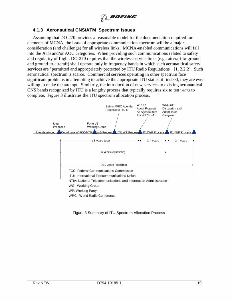
elements of MCNA, the issue of appropriate communication spectrum will be a major consideration (and challenge) for all wireless links. MCNA-enabled communications will fall into the ATS and/or AOC categories. When providing such communications related to safety and regularity of flight, DO-270 requires that the wireless service links (e.g., aircraft-to-ground and ground-to-aircraft) shall operate only in frequency bands in which such aeronautical safety-services are "permitted and appropriately protected by ITU Radio Regulations". [1, 2.2.2]. Such aeronautical spectrum is scarce. Commercial services operating in other spectrum face significant problems in attempting to achieve the appropriate ITU status, if, indeed, they are even willing to make the attempt. Similarly, the introduction of new services to existing aeronautical CNS bands recognized by ITU is a lengthy process that typically requires six to ten years to complete. Figure 3 illustrates the ITU spectrum allocation process.
Idea developed ITU WP ProcessWG Process
Idea Proposed
Coordinate w/ FCC-NTIA
Form USWorking Group
Submit WRC AgendaProposal to ITU-R
ITU WP Process
WRC-nAdopt ProposalAs Agenda Item For WRC-n+1
WRC-n+1Discussion andAdoption orCarryover
ITU WP Process
3-4 years 3-4 years1-5 years (est)
6 years (optimistic)
>10 years (possible)
FCC: Federal Communications CommissionITU: International Telecommunications UnionNTIA: National Telecommunications and Information AdministrationWG: Working GroupWP: Working PartyWRC: World Radio Conference
Figure 3 Summary of ITU Spectrum Allocation Process
Rev NEW D794-10185-1 20
There is, however, some ambiguity about the entire ITU/AMS(R)S spectrum process. While the current SATCOM user links (1525-1559 MHz space-to-aircraft, 1626.5-1660.5 MHz aircraft-to-space) enjoy ITU footnote protection with the appropriate priority-precedence and pre-emption characteristics9, the corresponding feeder links (6425.0-6234.0 MHz earth-to-space, 3600.0-3629.0 MHz space-to-earth) have no such designation.10 This suggests that some combination of higher and lower level QoS provisions may be sufficient, provided that sufficient bandwidth is available.
4.1.4 Reliance on Commercial Software It is very difficult to believe that system, ground, satellite (if any), and avionics software for
links supporting MCNA would be developed from scratch to meet the most stringent (Level C?) communication requirement of DO-178B/DO-278. Any cost effective implementation would be forced to rely on a substantial amount of commercial telecommunications software.
4.1.5 Treatment of Commercial Quality of Service Provisions Another DO-270 requirement that can be expected to apply to all CNS/ATM services and
communications architectures is the requirement that "[e]ach element shall conform with applicable International and National Radio Regulations and aviation regulations governing the precedence and protection of aeronautical mobile safety communications."[1, 2.2.4] More detailed requirements specifying the levels of priority and need for precedence and, if necessary, preemption, are specified in subsequent sections.
The challenge for MCNA in this regard is the mapping of commercial Quality of Service (QoS) guarantees to the aeronautical communications market in a manner that can convince the responsible FAA organization (as yet unidentified, see 4.1.1 above) that the necessary level of safety can be maintained.
4.1.6 System/Service Provider Participation A system-approval process based on DO-270 can not be implemented without the detailed
support of the system/service provider. 11 In the cases of ARINC and Inmarsat, this is not likely to be a problem, as both organizations have previously demonstrated their willingness to support such efforts. Other commercial carriers, however, may not be as supportive.
9 Indeed, the requirements in DO-270 are based on those established by the SARPs and MOPS for the INmarsat
Aero H-related services. 10 Similarly, FAATSAT uses contracted satellite services to aid in the interconnection of the FAA terrestrial
network with remote sites. In this case, the FAATSAT links are considered part of the terrestrial network, with both ends controlled by FAA design. Therefore, FAATSAT is not a good model for MCNA, which is primarily concerned with ground-to-air and air-to-ground communications.
11 A sample evaluation of the DO-270 process for one potential system is contained in Appendix I to this Attachment.
Rev NEW D794-10185-1 21
4.1.7 High Layer Integrity Issues One of the key requirements on any MCNA sub-network will be the very high integrity
required for aeronautical safety services. The high integrity requirements are linked to the aircraft safety assessment process carried out as part of the operational approval. As suggested earlier, it may be possible that application-layer error detection and correction might be a useful approach. If done properly, such an approach might also lessen the software approval/certification demands. Most of today's aeronautical links, however, place the burden of the integrity requirement12 on the physical link itself (OSI Layer 3 and below) and not on the application. The challenge, therefore, is to develop and validate the rational for high layer integrity in a manner that can be defended during the (as yet undefined) system approval process.
The primary challenge of this approach is that it appears to be different from what the FAA is used to on other links and, therefore, may encounter some resistance. On the other hand, there is some precedent for this approach, namely the application layer error detection mechanisms specified in ARINC 622 [21] and ICAO ATN [22] documentation. DO-296 [19] supports such higher layer error detection and correction as part of its architectural risk mitigation strategy.13
4.2 Challenges for Avionics Approval
4.2.1 MOPS Technique-specific Appendices One step in the approval process is the creation of technique-specific documentation. This
documentation would correspond in many ways to that described in some detail in DO-262 [7]. The documentation would, in essence, become a formalized description of the communications performance that could be expected of the communication system.
The challenge associated with the acceptance of such documentation is that DO-262 applies only to "next generation" , i.e., beyond Inmarsat Aero H global beam, satellite services, and not to other line-of-sight, beyond line-of-sight, mesh-networked, or ground-to-ground services that might be proposed. We believe that the intent and much of the methodology of DO-262 is directly applicable to such problems with little or no modification. Within the FAA, it is likely that the AIR organization would have responsibility for the approval of such documentation.
4.2.2 Reliance on Commercial Software Reliance on any commercial communications service for the Air-to-Ground link will mean
reliance on the software that implements the functionality of that link. All modern systems are largely, if not totally, based on software for implementation the OSI or TCP/IP protocol stacks. The challenge here is the proper assessment of system safety implications, and the success (or lack of success) that individual commercial service providers may have in mapping their internal
12 Integrity is defined as the probability of providing error-free information to the pilot or aircraft systems. 13 Error checking at higher protocol layer stacks may have an adverse effect on mean transfer delay, and,
therefore, may adversely affect the communications performance achieved by specific networks, i.e., the ACP. This could then become a limitation in delay critical applications.
Rev NEW D794-10185-1 22
software development process and artifacts to the formalized methodology of DO-178B14. At the current time, there are no good publicly available benchmarks for how to accomplish this task, how much credit may be given, or what limitations in communications functionality might result. In current practice, "commercial" software is always considered as DO-178B "Level E", and is not available for safety applications. As noted earlier, even AOC communications are considered part of safety services, so it is natural to assume that any MCNA implementation will have to obtain some higher level approval, possibly as high as "Level C".
4.3 Challenges Aircraft Approval
4.3.1 Well-defined and Meaningful RCP Standards It seems that the MCNA vision aligns well with the forward-looking work underway in
RTCA Special Committee 189. Other RTCA committees and FAA Advisory Circulars have developed criteria and actual certification procedures that approve aircraft to operate with various levels of Required Navigation Performance (RNP) capability. As yet, however, there are no instances of developing, approving and applying aircraft-wide Required Communication Performance (RCP) standards to the actual operational approval of an aircraft. Therefore, this is a significant challenge for ultimate MCNA certification and approval.
4.3.2 Cabin/Cockpit Isolation Issues There are currently divergent views regarding the degree and implementation of isolation
between cabin and cockpit data communication systems. Airbus supports complete isolation of the systems. Boeing appears to support complete integration of the systems. Both approaches have advantages and disadvantages from an aircraft approval standpoint. Any final certification plan will face the challenge of being sufficiently flexible to address both approaches.
14 The reference here is only to DO-178B, as DO-278 applies to ground infrastructure.
Rev NEW D794-10185-1 23
5.1 System Approval
Conclusion 1: There is currently no FAA acknowledged process in place by which a commercial system can be approved for the transmission of safety services, including both ATS and AOC services. Current commercial systems used for these purposes have been approved and/or developed in an ad hoc manner appropriate to the needs of the community at the times of their development. There is, however, a model for the information required and the methodology by which that information could be developed. This model is contained in DO-270 [1]. A strawman consideration of DO-270 to Inmarsat Swift Broadband (SBB) services is contained in Appendix I to this report.
Recommendation 1: A cooperative effort between FAA and interested parties should be undertaken to develop and approve an agreed-upon process for the submission and review of relevant data and the approval of commercial services for AOC and ATS applications. One possible means might be the development of System/Service Type Certification or System/Service Supplemental Type Certification.
Recommendation 2: In parallel with the development of the recommended process, a separate cooperative effort between FAA or NASA and a selected system/service provider should be undertaken to complete and validate the required documentation. Joint funding of such an effort, possibly by CRDA or other such vehicle, could provide the economic incentive for active service provider participation. Conducting such an effort in parallel with the development of the FAA approval process would provide the opportunity for real-time feedback and process improvement.
Conclusion 2: There is no widely acknowledged paradigm for the use of commercial terrestrial telecommunications infrastructure for safety information, even though this use occurs every day. The software certification issues related to DO-278 are not well documented: in fact, it is not certain that DO-278 has been applied to such use. This suggests that there may be mechanisms by which the terrestrial telecommunication infrastructure model could be extended to include the air-ground links.
Recommendation 3: An effort should be made to assess how the use of terrestrial telecommunications infrastructure differs from the use of wireless telecommunications infrastructure. This assessment should consider how similarities can be exploited to simplify the approval process. This task could be implemented by either, or both, of the groups established in accordance with the two previous recommendations.
5.2 Avionics Approval and Certification
Conclusion 3: There is currently no FAA acknowledged process in place by which avionics suitable for use with a commercial system can be approved for the transmission of safety
5 CONCLUSIONS & RECOMMENDATIONS
Rev NEW D794-10185-1 24
services, including both ATS and AOC services. There is a model for the information required and the methodology by which that information could be developed. This model is contained in DO-262 [7]. It is uncertain which organization within FAA would receive or approve such documentation as a basis for a TSO- or PMA-based approval.
Recommendation 4: A cooperative effort between FAA and interested parties should be undertaken to develop and approve an agreed-upon process for the submission and review of relevant data and the approval of avionics supporting commercial services for AOC and ATS applications. DO-262 should be used as a baseline for this effort. Because of the overlapping of the system and avionics approval processes, it is possible that this effort can be combined with that of Recommendation 1, above.
Recommendation 5: Additional investigation into methods to encourage the use of commercial software in communications avionics should be undertaken. It is possible that the current SC-205 activities will encompass this issue. RTCA should be encouraged to review the SC-205 Terms of Reference and incorporate changes to accomplish this objective as appropriate.
Recommendation 6: NASA or FAA should consider funding an effort to develop a TCP/IP stack that is DO-178B certified to Level C or higher and made generally available to spur the development of lower cost IP- compliant avionics. Such a product would eliminate the need for each avionics manufacturer to develop a separate certified IP stack and recoup those development costs over a small set of avionics. The effort should concentrate on a concise set of TCP/IP requirements based on avionics-specific tailoring of accepted standard, such as IPV6, a widely supportable, well-documented and traceable design, well-documented and traceable code in a widely supported language, such as C++, and a standard test suite. The effort would not encompass final instantiation-specific certification issues, which would be left to the equipment manufacturer.
5.3 Aircraft Approval and Certification
Conclusion 4: Once the significant questions raised regarding system and avionics certification are resolved, the current aircraft certification process appears to be sufficient to support the approval for individual services. However, the current process may not be sufficient for anticipated future RCP applications.
Recommendation 7: A cooperative effort between FAA and interested parties, possibly including the efforts of RTCA Special Committees, should be undertaken to develop details of how RCP could be applied on an aircraft-by-aircraft basis, with the goal of simplifying or reducing aircraft equipage. The role of software defined radios should be considered within this context.

Rev NEW D794-10185-1 25
AAS Advanced Automation System
ACAST Advanced CNS Architectures and Systems Technologies
AC (FAA) Advisory Circular
ACCC Area Control Computer Complex
ACO Aircraft Certification Office
AERA Automated En-Route Air Traffic Control
AIR (FAA) Aircraft Certification Branch
AOC Aeronautical Operational Control, equivalently Airline or Aircraft Operational Control
ARSA
ATC Air Traffic Control
ATM Air Traffic Management
ATS Air Traffic Services
CAA Civil Aviation Authority (or Administration, or Agency)
CNS (Aeronautical) Communication, Navigation and Surveillance
DFDAU Digital Flight Data Acquisition Units
FAA Federal Aviation Administration
FIS Flight Information Service
FMC Flight Management Computer
FMS Flight Management Systems
GRC (NASA) Glenn Research Center
ICAO International Civil Aviation Organization
6 ACRONYMS
Rev NEW D794-10185-1 26
ITU International Telecommunications Union
MASPS Minimum Aviation System Performance Standards
MCNA Mobile Communications Network Architecture
MOPS Minimum Operational Performance Standards
NAS National Airspace System
NOTAM Notice to Airmen
PMA Parts Manufacturer Approval
RTCA RTCA, Inc.; formerly Radio Technical Commission on Aeronautics
SARPs (ICAO) Standards and Recommended Practices
SATCOM Satellite Communication. When used without additional qualifiers, SATCOM is usually intended to mean communications using Inmarsat satellites.
SSSTC or S3TC
System/Service Supplemental Type Certificate
SSTC or S2TC
System/Service Type Certificate
STC Supplemental Type Certificate
TC Type Certificate
TCAS Threat Alert/Collision Avoidance System
TCCC Tower Control Computer Complexes
TSO Technical Standard Order
TNAS Transforming the NAS
VFR Visual Flight Rules
.
Rev NEW D794-10185-1 27
[1] "Minimum Aviation System Performance Standards for Aeronautical Mobile Satellite (Route) Services (AMS(R)S)," RTCA, Inc., Washington, D.C., DO-270, 2001.
[2] "Guidance on Aeronautical Mobile Satellite Service (AMSS) End-to-End System Performance," RTCA, Inc., Washington, DC, 1995.
[3] "Guidelines on AMS(R)S Near-Term Voice Implementation and Utilization," RTCA, Inc, Washington, D.C., DO-222, April 29, 1994.
[4] "Minimum Operational Performance Standards for Aeronautical Mobile Satellite Services (AMSS)," RTCA, Inc., Washington, D.C., DO-210D, including Change 1 and Change 2, 2001.
[5] "Annex 10 to the Convention International Civil Aviation," International Civil Aviation Organization, Montreal, 1996.
[6] "Assessment of Radio Frequency Interference Relevant to the GNSS L5/E5A Frequency Band," RTCA, Inc, Washington, D.C., DO-292, July 29, 2004.
[7] "Minimum Operational Performance Standards for Avionics Supporting Next Generation Satellite Systems (NGSS)," RTCA, Inc., 2000.
[8] "Aircraft Certification Service Mission, Responsibilities, Relationships and Programs," Department of Transportation, Federal Aviation Administration, Washington, D.C., Order 8100.5A, September 30, 2003.
[9] "Type Certification," Department of Transportation, Federal Aviation Administration, Washington, DC, Order 8110.4B, April 24, 2000.
[10] "Application Guide for Obtaining a Supplemental Type Certificate," Department of Transportation, Federal Aviation Administration, Washington, DC, Advisory Circular AC 21-40, May 6, 1998.
[11] “Parts Manufacturer Approval Process," Department of Transportation, Federal Aviation Administration, Washington, DC, Order 8110.42A, March 31, 1999.
[12] "Technical Standard Order Program," Department of Transportation, Federal Aviation Administration, Washington, DC, Order 8150.1B, May 12, 2002.
[13] "Airworthiness Inspection Handbook," Flight Standards Service, http://www.faa.gov/avr/afs/faa/8300/, Order 8300.10, February 24, 2004.
[14] "Production Approval and Certificate Management Procedures," Department of Transportation, Federal Aviation Administration, Washington, DC, Order 8210.2D, August 17, 2004.
[15] "Airworthiness Certification of Aircraft and Related Products," Department of Transportation, Federal Aviation Administration, Washington, DC, Order 8130.2F, November 5, 2004.
[16] "Software Considerations in Airborne Systems and Equipment Certification," RTCA, Inc., Washington, D.C., DO-178B, 1992.
[17] "Guidelines for Communication, Navigation, Surveillance and Air Traffic Management (CNS/ATM) Systems Software Integrity Assurance," RTCA, Inc., Washington, DC, DO-278, March 5, 2002.
7 References
Rev NEW D794-10185-1 28
[18] "Final Report for Clarification of DO-178B "Software Considerations in Airborne Systems and Equipment Certification"," RTCA, Inc., Washington, DC, DO-248B, October 12, 2001.
[19] [19] "Safety Requirements Standard for Aeronautical Operational Control (AOC) Datalink Messages," RTCA, Inc., Washington, D.C., DO-296, October 19, 2004.
[20] [20] "FAA STC Process," ASTech Engineering, Inc, www.astech-engineering.com/systems/avionics/aircraft/faastcprocess1.html, April 6, 2005.
[21] [21] "ATS Data Link Applications Over ACARS Air-Ground Network," ARINC, Inc., Annapolis, MD, ARINC Specification 622-4, October, 2001.
[22] [22] "Manual of Technical Provisions for the Aeronautical Telecommunications Network (ATN), Standards and Recommended Practices," International Civil Aviation Organization, Montreal, QC, Canada, ICAO DOC 9705, Edition 3, 2001.
Rev NEW D794-10185-1 29
A Preliminary Assessment of Swift Broadband (SBB) as a Next Generation Satellite System
Prepared By: E. F. Charles LaBerge, Honeywell CST CoE, Columbia, MD
Date: March 22, 2005
Revision: First Draft
Document Number: CSTCOE-EFCL-0221A
Release Notes and Disclaimer: This document contains the opinions of technical experts at the Honeywell Communications
and Surveillance Center of Excellence. It has not been approved or authorized by Inmarsat PLLC or any of its subsidiaries as representing Inmarsat plans for Swift Broadband services.
This document has been prepared in compliance with existing non-disclosure agreements between Honeywell and Inmarsat, and contains only Swift Broadband information that is readily
available in the public domain.
APPENDIX A
Rev NEW D794-10185-1 30
TABLE OF CONTENTS
1 Introduction........................................................................................................................31 1.1 Document Organization and Scope ......................................................................31 1.2 Caveats regarding Inmarsat ..................................................................................32 1.3 Conclusions ..........................................................................................................32 1.4 Open Issues...........................................................................................................32
2 SUBNETWORK PERFORMANCE REQUIREMENTS .................................................34 2.1 General Requirements ..........................................................................................34 2.2 Specific Requirements..........................................................................................35
2.2.1 Standard Operating Conditions ...................................................................35 2.2.2 Spectrum Requirements ..............................................................................36 2.2.3 Coverage Volume........................................................................................40 2.2.4 Priority, Precedence and Preemption ..........................................................40 2.2.5 Subnetwork Installed Communications Performance (ICP) .......................42 2.2.6 Service Monitoring......................................................................................52 2.2.7 Subnetwork Interoperability........................................................................53
3 SUBSYSTEM REQUIREMENTS ....................................................................................57 3.1 Performance Partitioning Methodologies.............................................................58
3.1.1 RF Performance...........................................................................................58 3.1.2 Transfer Delay Partitioning Methodology ..................................................59 3.1.3 Integrity Methodology.................................................................................60 3.1.4 Availability Methodology ...........................................................................61 3.1.5 Continuity Methodology .............................................................................64
3.2 AES Subsystem Requirements .............................................................................66 3.3 Satellite Network Infrastructure (SNI) Requirements ..........................................67
3.3.1 SNI Performance Requirements ..................................................................67 3.3.2 SNI Functional Requirements .....................................................................70
Rev NEW D794-10185-1 31
8 Introduction In 1999-2001, RTCA and ICAO began to explore the development of "generic" standards for SARPs15, MASPS16, and MOPS17. ICAO developed, approved through the Air Navigation Commission, and circulated under State Letter a generic "Chapter 12" SARPs document for inclusion in the volume of ICAO Annex 10 dedicated to aeronautical telecommunications. The chapter was not including in Annex 10 due to several dissenting opinions from member states. These dissenting opinions, however, had nothing to do with the technical content, organization or validity of the generic SARPs approach. In fact, recent actions by ICAO Aeronautical Communications Panel, Working Group M, have begun to retroactively apply the principles of the draft Chapter 12 SARPs to existing Chapter 4 SATCOM SARPs, in effect adopting Chapter 12 as the proper approach.
Similarly, RTCA published MOPS as RTCA DO-262 [1] and MASPS as RTCA DO-270 [2] following a generic service approach. Compliance with the MASPS for the service and the MOPS for the avionics equipment then becomes a process of documentation and analysis that establish the technique-specific standards for the system and avionics, respectively. As of early 2005, no system or avionics equipment has been approved for use under the terms of either DO-270 or DO-262. It is clear, however, that a number of state-of-the-art and near-state-of-the-art systems are candidates for such approval, and that one or more of these systems may be a subnetwork of the MCNA.
8.1 Document Organization and Scope This document starts from the text of DO-270, the generic MASPS, and does several things. First, each of the individual requirements of the MASPS is uniquely identified and categorized. The categories including the following:
F: system functional performance
P: quantitative system performance criteria
D: documentation required to meet the requirements of the MASPS
C: computational assumptions or rules necessary to assure consistency of presentation of the information required in the documentation
R: regulatory requirements regarding standards established by regulatory bodies outside of the normal aeronautical certification/approval process.
Each requirement is then viewed from the perspective of the Swift Broadband (SBB) service proposed by Inmarsat. Items that can clearly be stated and described are discussed. Items that affect only the requisite documentation are noted. Because development of SBB is still underway, there are a number of items in the MASPS that
15 SARPs: Standards and Recommended Practices, ICAO system-level specs. 16 MASPS: Minimum Aviation Performance Standards, RTCA system-level specs 17 MOPS: Minimum Operational Performance Standards, RTCA equipment (avionics) level specs.

Rev NEW D794-10185-1 32
can be satisfied only by the release of information contained in documentation that currently remains as Inmarsat proprietary. These items are noted.
The document organization in Section 2 and Section 3 exactly matches DO-270. DO-270 Section 1 is replaced by a case-study appropriate introduction. DO-270 Section 4, which deals with verification, is deleted, since it presents details about the documentation to be provided.
Comments on the status of each requirement are provided immediately following that requirement. All comments are delineated by means of indentation, a "SBB Case Study:" prefix, and italicized text.
8.2 Caveats regarding Inmarsat Inmarsat has not participated or been requested to participate in the presentation of this document. This document in no way represents any intent of Inmarsat to either seek or not seek NGSS approval for SBB. This document is solely intended as a case study of what information might be required, what might be available, and what might require additional development or computation.
8.3 Conclusions The conclusion of this case study is that much, perhaps more than half, of the information required for a SBB submission under DO-270 is available. Much of that, however, is not releasable at this time, as Inmarsat has not made full public release of aeronautical SBB information. Many of the difficult hurdles may be addressed by similarity to DO-210D (Aero H) systems. There are, however, coverage and availability issues that will require a substantial amount of new analysis. The remainder of the information required by DO-270, as well as all collating and formatting in the standard pro forma tables required of DO-270, would require additional development and computational effort. Although this effort is likely to be substantial, it is, we believe, far less than the comparable effort to develop and completely new MASPS and shepherd it through the RTCA process.
8.4 Open Issues A number of open issues result from this case study, including the following:
• The FAA really doesn’t know how DO-270 would be used. At this time, no service provider has come forward to request approval under the process, and it isn't certain exactly who would provide such approval or exactly what the DO-270-to-approval process would be. There currently aren't any MASPS-based "system TSO" documents that would provide a template for these activities.
• The role of RTCA is uncertain. This is actually strongly related to the previous point. In the past, RTCA Special Committees have been the clearing house and technical review for all system and avionics issues. In the process, the RTCA "DO" documents become the focus for the actual TSO. As noted above, no system-level TSO process exists. Furthermore, DO-270 specifically anticipates the development of system-specific technical detail for a number of systems. Questions related to who develops, documents, and reviews this information are unresolved, and, to a large extent, unasked.
Rev NEW D794-10185-1 33
• Certification issues – Software and Hardware levels – still need to be established and resolved. SBB is a commercial service. The current predecessor hardware and software for Swift 64 (S64) is all commercial off-the-shelf, corresponding to DO-178B Level E. At this time, neither S64 or the terrestrial version of SBB carry aeronautical safety information, so this is not a concern. Portions of the predecessor Aero H equipment and software are Level D (more controlled than commercial practice), and there is pressure from FAA and various CAAs to increase this to Level C. The software-intensive nature of SBB may make such increased qualification cost-prohibitive.
• Recognizing the problem raised in the previous bullet, the question becomes "How can we avoid the penalty of approving the entire software to anything higher than Level E?" There is some experience with multi-level software within Honeywell. Issues regarding such software need to be discussed and agreed upon within the SWIM/MCNA community. Such agreements need to specifically include agreement by the various certification elements within the FAA.
• DO-270, like all predecessor RTCA and ICAO documents, requires that a service have Priority, Precedence, and Preemption (PPP) for safety messages. These requirements were based on the original very low rate Inmarsat aeronautical services, as well as requirements for mean and 95% transfer delay. Given the wider bandwidth and correspondingly faster response times, the new technology begs the question "What do the requirements on PPP mean in a broadband system?" Are bandwidth and QoS provisions sufficient to eliminate the need for specific PPP requirements? Stated differently, "Can they be replaced by QoS guarantees, albeit at a very high level?"
• After reviewing DO-270, it isn't clear that the document is really based on a full implementation of a true packet system. Although much has been spoken or written about the ATN as a packet network of the future, and although DO-270 speaks in terms of packet latency and transfer delay, there are elements of DO-270 that appear to seek assurances that can only be provided by circuit-switched data paths. Is the FAA really ready for the statistical uncertainties inherent in any packet network?
• The computations involving SBB availability will be very intricate. This is especially true given the combination differing coverages (area spot beam, regional spot beam, global beam) and differing connection alternatives (connection-based versus connectionless) for various services.
• The preliminary work done in this case study is based on the Core Europe Traffic model [3, 4]. We probably want to probe FAA/Eurocontrol for any updates to this Core Europe Model, as well as any extensions to oceanic regions.
• The DO-270 process requires full participation by the service and network provider(s), Completion of this process will require full and open participation by the Inmarsat experts, as well as agreement by Inmarsat to release certain SBB data that is now deemed proprietary. Given the competitive nature of the mobile satellite services marketplace, Inmarsat will have to be convinced of the business case supporting such release.
Rev NEW D794-10185-1 34
9 SUBNETWORK PERFORMANCE REQUIREMENTS
Each AMSS system qualifying for AMS(R)S shall (1D) address each requirement of this document in its system-specific normative attachment to this document.
SBB Case Study: Documentation
For requirements that contain pro-forma formats for characterizing performance data, those formats shall (2D) be followed.
SBB Case Study: Documentation
If a given AMS(R)S provider desires to offer more than one level of AMS(R)S service (for example, services offered in global beams versus services offered in spot beams) the required information shall (3D) be included for each AMS(R)S service level offered.
SBB Case Study: SBB potentially Narrow spot, Regional Spot, Global beams with drastically different data rates.
The performance declared in accordance with this MASPS shall (4D) be the minimum performance for the specific service.
SBB Case Study: Documentation
Notes: 1. The term AMS(R)S service level should not be confused with the required priority levels identified in Section 2.2.4. It is required that each AMS(R)S service, however defined, support at least the three priority levels specified in Section 2.2.4.
2. It is strongly recommended that each system organize its attachment to follow the structure of this MASPS.
9.1 General Requirements The AMS(R)S subnetwork shall (5F) meet all pertinent airworthiness, human factors and operational requirements including alerts, controls and frequency management considerations.
SBB Case Study: Same as current Chapter 4/210D equipment. This requirement is flowed down to the MOPS (DO-262)
Requirements relating to carriage of AMS(R)S equipment on aircraft and implementation of ground infrastructure supporting AMS(R)S shall (6R) be in accordance with national requirements, regional agreements or international agreements, including the level of system capability, as appropriate for Air Traffic Service operations and Aeronautical Operational Control.

Rev NEW D794-10185-1 35
SBB Case Study: TBD by regulatory (CAA/FAA) authorities, no requirement at this time
9.2 Specific Requirements Each system desiring approval for AMS(R)S operations shall (7D) declare its performance characteristics in a system-specific attachment, using the pro forma of Table 2-1.
9.2.1 Standard Operating Conditions
At the AMS(R)S system level, the standard operating conditions shall (8F) be as established by the traffic model defined in accordance with Section 2.2.5.1.1.
SBB Case Study: This is a functional requirement that, in turn is specified by the traffic model. See SBB comment to 9C).
The minimum acceptable traffic model, established on a "per aircraft basis", shall (9C) be as defined in Appendix E.
SBB Case Study: The traffic models developed for the MACONDO study [4] are far more detailed and explict than those defined in DO-270, appendix E. Honeywell has made additional extensions of this model, and has provided these extensions to NASA Glenn [5].
It would be reasonable to use MACONDO model without surveillance applications (i.e. ADS-B and TIS-B) as the traffic model. Using the Extended MACONDO models described in [5], and assuming (worst case) that oceanic load was equivalent to the core continental load, we see a downlink requirement of about 850 bps/ac and an uplink load of 188 bps/ac. For 300 aircraft [6-10] in the North Atlantic, this translates into 255 kbps down and 56.4 kbps up, suggesting that a single SBB channel could handle all of the ATS traffic. Although a good model for AOC traffic does not exist, these values are 60% and 15% of the advertised maximum SBB bandwidth. Therefore, it appears that two or three 200 kHz SBB channels should be able to handle all ATS and all AOC traffic, at least in an oceanic region.
The aircraft density is much greater, of course, in continental airspace. Again using the MACONDO traffic model, we have 696 aircraft in the European upper altitude airspace and 435 in the periphery airspace (some of the periphery are an overlap with the oceanic, but this is not clearly delineated in MACONDO. Assuming that TMAs are covered by cheaper line of sight links (a big assumption, given the limited bandwidth), we could have 1131 aircraft. The extended MACONDO model then predicts a downlink ATC load (not including ADS-B) of 960 kbps (over all core Europe) and an uplink ATC load (not including TIS-B) of 213 kbps. Thus, loading over a large, dense, continental airspace could easily require multiple channels (3? 4?) based on acceptable performance. AOC – that is, most SWIM applications, only ADD to this load, albeit with reduced latency and transfer delay requirements.
The actual numbers of channels for oceanic or continental airspace would depend on an Erlang [Opnet Peak-to-Mean Statistical Multiplexing terms].

Rev NEW D794-10185-1 36
loading analysis for given quality of service. Given the safety (ATS-AOC) applications, an ARQ/HARQ protocol is appropriate, suggesting that the delay analysis in [11, 12] might also be applied. Completing such analyses is outside the scope of GCNSS Phase II.
9.2.2 Spectrum Requirements
When providing AMS(R)S communications, the service links (i.e.; aircraft-to-satellite and satellite-to-aircraft links) shall (10R] operate only in frequency bands in which AMS(R)S is permitted and appropriately protected by ITU Radio Regulations.
SBB Case Study: SBB operates in bands with ITU AMS(R)S designation.]
Each element of the AMS(R)S Subsystem (including AESs, NCCF, GESs, and the constellation) shall (11R] conform with applicable International Radio Regulations and National radio regulations (e.g., in the United States, the FCC Rules and the NTIA Manual) of each state in the declared service volume.
SBB Case Study: Inmarsat services meet this requirement.]
Each AMS(R)S system shall (12D) provide the following information in its normative system-specific attachment:
1) Operating frequency range(s), including frequency range(s) used for AMS(R)S, in which AMSS operations are permitted by the system;
2) Operating frequency range(s) in which AMS(R)S operations are made possible by system or element design; and
3) Details regarding any special aspects of the system or element designs that are intended to cater to special requirements of AMS(R)S.
SBB Case Study: Documentation
9.2.2.1 Emission Designators
Each AMSS system providing AMS(R)S shall (13D) state the emission designator(s) for the various transmissions that support AMSS and AMS(R)S.
SBB Case Study: Documentation

Rev NEW D794-10185-1 37
Table 2-1. Pro Forma for Swift Broadband System Characteristic Declaration
Symbol Characteristic Paragraph Ref.
Declared Value
no symbol
Compliancy – ICAO Chapter 4 or NGSS
1.2.1 NGSS
no symbol
AMS(R)S transmit frequency band (user)
2.2.2 1631.5-1660.5
no symbol
AMS(R)S receive frequency band (user) 2.2.2 1530-1559
no symbol
GES-Satellite Uplink Frequency Band B.2 Same as ICAO Chapter 4
no symbol
GES-Satellite Downlink Frequency Band
B.2 Same as ICAO Chapter 4
no symbol
Satellite-Satellite Link Frequency Band 2.2 n/a
no symbol
NCCF Satellite Uplink Frequency Band 2.2 Same as ICAO Chapter 4
no symbol
Satellite-NCCF Downlink Frequency Band
2.2 Same as ICAO Chapter 4
no symbol
Susceptibility 2.2.2.2.2 <tbd>
Ω Coverage volume 2.2.3 Long -180, 180, Lat 72N – 72S
ω1 volume 1 2.2.3 n/a
2ω volume 2 2.2.3 n/a
3 4, ,...ω ω ω volume 3, volume 4 ,... , volume n, 2.2.3 n/a
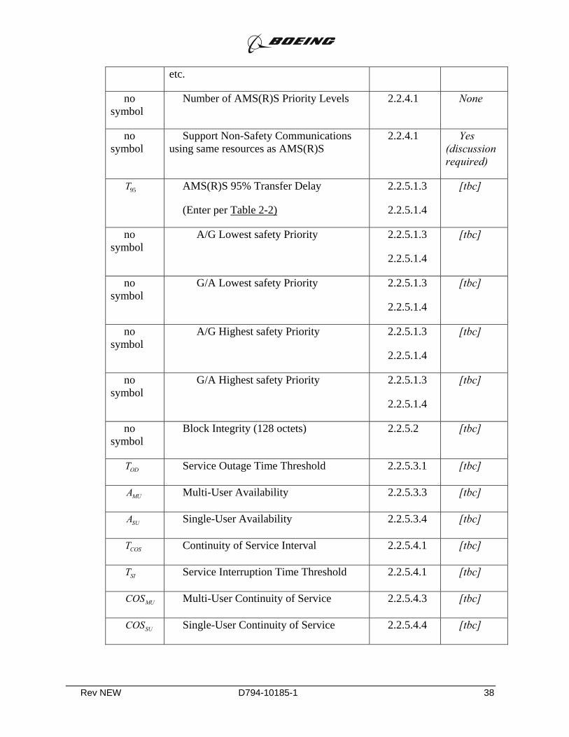
Rev NEW D794-10185-1 38
etc.
no symbol
Number of AMS(R)S Priority Levels 2.2.4.1 None
no symbol
Support Non-Safety Communications using same resources as AMS(R)S
2.2.4.1 Yes (discussion required)
95T AMS(R)S 95% Transfer Delay
(Enter per Table 2-2)
2.2.5.1.3
2.2.5.1.4
[tbc]
no symbol
A/G Lowest safety Priority 2.2.5.1.3
2.2.5.1.4
[tbc]
no symbol
G/A Lowest safety Priority 2.2.5.1.3
2.2.5.1.4
[tbc]
no symbol
A/G Highest safety Priority 2.2.5.1.3
2.2.5.1.4
[tbc]
no symbol
G/A Highest safety Priority 2.2.5.1.3
2.2.5.1.4
[tbc]
no symbol
Block Integrity (128 octets) 2.2.5.2 [tbc]
ODT Service Outage Time Threshold 2.2.5.3.1 [tbc]
MUA Multi-User Availability 2.2.5.3.3 [tbc]
SUA Single-User Availability 2.2.5.3.4 [tbc]
COST Continuity of Service Interval 2.2.5.4.1 [tbc]
SIT Service Interruption Time Threshold 2.2.5.4.1 [tbc]
MUCOS Multi-User Continuity of Service 2.2.5.4.3 [tbc]
SUCOS Single-User Continuity of Service 2.2.5.4.4 [tbc]
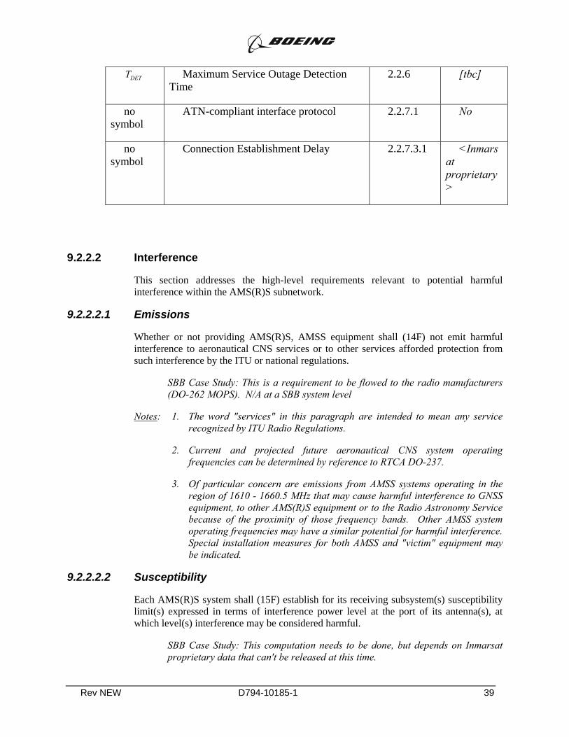
Rev NEW D794-10185-1 39
DETT Maximum Service Outage Detection Time
2.2.6 [tbc]
no symbol
ATN-compliant interface protocol 2.2.7.1 No
no symbol
Connection Establishment Delay 2.2.7.3.1 <Inmarsat proprietary>
9.2.2.2 Interference
This section addresses the high-level requirements relevant to potential harmful interference within the AMS(R)S subnetwork.
9.2.2.2.1 Emissions
Whether or not providing AMS(R)S, AMSS equipment shall (14F) not emit harmful interference to aeronautical CNS services or to other services afforded protection from such interference by the ITU or national regulations.
SBB Case Study: This is a requirement to be flowed to the radio manufacturers (DO-262 MOPS). N/A at a SBB system level
Notes: 1. The word "services" in this paragraph are intended to mean any service recognized by ITU Radio Regulations.
2. Current and projected future aeronautical CNS system operating frequencies can be determined by reference to RTCA DO-237.
3. Of particular concern are emissions from AMSS systems operating in the region of 1610 - 1660.5 MHz that may cause harmful interference to GNSS equipment, to other AMS(R)S equipment or to the Radio Astronomy Service because of the proximity of those frequency bands. Other AMSS system operating frequencies may have a similar potential for harmful interference. Special installation measures for both AMSS and "victim" equipment may be indicated.
9.2.2.2.2 Susceptibility
Each AMS(R)S system shall (15F) establish for its receiving subsystem(s) susceptibility limit(s) expressed in terms of interference power level at the port of its antenna(s), at which level(s) interference may be considered harmful.
SBB Case Study: This computation needs to be done, but depends on Inmarsat proprietary data that can't be released at this time.

Rev NEW D794-10185-1 40
The level(s) shall (16D) be stated and justified in the system's normative attachment, and shall (17] be consistent with the RF link budget analysis required by Section 3.1.1.
SBB Case Study: This computation needs to be done, but depends on Inmarsat proprietary data that can't be released at this time.
Note: The susceptibility limit is derived from the ratio ∆T/T, where ∆T is the incremental equivalent noise temperature of the total external interference power and T is the equivalent noise temperature of the receiver system, including the effects of any interference generated within the satellite system itself. Both noise temperatures are expressed in Kelvins. This is equivalent to the recommendations of RTCA DO-215A and ITU M.1234.
9.2.3 Coverage Volume
The coverage volume(s) of any satellite constellation is defined as that volume of airspace delineated by an area of the Earth's surface and an altitude above the Earth's surface, within which the ICP and service requirements of this document are satisfied.
Each AMS(R)S system shall (18D) declare in its associated normative attachment the boundaries of such coverage volume(s).
SBB Case Study: For the purpose of the GCNSS exercise, we'll assume the Aero H coverage volume. This may not be completely depending on the number of SBB-capable satellites Inmarsat launches.
Notes: 1. It is expected that the coverage of satellite subnetworks will have little dependence on the altitude of user aircraft.
2. It is recognized that satellite constellations providing AMS(R)S may have differing coverage characteristics; e.g., a geosynchronous Earth orbit constellation could be characterized by fixed "global" and/or spot beams, and a low or medium Earth orbit constellation could be characterized by a multiplicity of dynamic spot beams over the Earth's surface. Coverage afforded by an AMS(R)S System, or portion thereof, may also be delineated by technical, regulatory and/or service agreement reasons.
9.2.4 Priority, Precedence and Preemption
Each element of the AMS(R)S Subsystem (including AESs, GESs and the constellation) shall (19R] conform with applicable International and National Radio Regulations and aviation regulations governing the precedence and protection of aeronautical mobile safety communications.
SBB Case Study: QoS, including priority, precedence, and preemption may not be supported by the raw SBB connection, but could be implemented in aeronautical gateways at both ends. The "access to the channel" problem could be overcome if there is sufficient aero demand to assure "aero-only" RF channels. This may or may not be in Inmarsat plans.

Rev NEW D794-10185-1 41
Each AMS(R)S system shall (20D) address each requirement of this section in its system-specific normative attachment to this document with a complete description of the mechanisms enabling the system to meet the requirements.
SBB Case Study: This is a documentation requirement.
9.2.4.1 Priority Levels
The AMS(R)S system, and its elements as appropriate, shall (21P) support not fewer than three AMS(R)S priority levels at the subnetwork interfaces.
SBB Case Study: SBB doesn't provide these directly, but they could be easily provided by the avionics/terrestrial AMSS gateway functions.
There is a techno-philosophical question that applies to SBB and all other broadband systems. The basic ICAO/ITU/RTCA requirements on latency, etc., make some assumptions about channel bandwidth that may not be accurate for broadband channel. If, for example, we could show that in an ARQ/HARQ system 99% of all packets are delivered within three transmissions retrys, and that the expected delay for 3 retries is small with respect to the permissible transfer delay, then why would PPP be required at all? This is an issue that I would expect Inmarsat and CBB to bring up when the time comes. AMS(R)S purists will hate the idea, but I really don't see anything wrong with it. Note that the mean transfer delay problem in noise channels with feedback errors is discussed in the research literature[11-13]
[At least different priority levels ATM-like CBR-VBR-ABR(?) talk of deploying more 3G type PP mechanisms Circuit/priority levels.May have hooks to provide].
If the system accepts non-safety blocks for transmission, at least one (lowest) priority level shall (22F) be added for non-safety traffic.
SBB Case Study: SBB doesn't provide these directly, but they could be easily provided by the avionics/terrestrial AMS(R)S gateway functions
If the system accepts blocks for transmission that contain either no priority indicator or a null priority indication, each such block shall (23F) be marked upon entry with a non-safety priority level and shall (24F) be treated as such in subsequent processing within the system.
SBB Case Study: SBB doesn't provide these directly, but they could be easily provided by the avionics/terrestrial AMS(R)S gateway functions
The AMS(R)S system shall (25F) forward a block priority indicator to the succeeding subsystem or end-user terminal.
Note: For the purpose of this document the three AMS(R)S priorities are designated as Distress/Urgency (highest safety priority), Flight Safety, and Other Safety (lowest safety priority). Non-safety traffic is designated as Non-Safety.
SBB Case Study: SBB doesn't provide these directly, but they could be easily provided by the avionics/terrestrial AMS(R)S gateway functions
Rev NEW D794-10185-1 42
9.2.4.2 Precedence
Each AES and GES shall (26F) ensure that higher priority blocks are not delayed by the transmission and/or reception of lower priority messages.
SBB Case Study: SBB doesn't provide these directly, but they could be easily provided by the avionics/terrestrial AMS(R)S gateway functions
9.2.4.3 Preemption
Lower priority messages shall (27F) be preempted, if necessary, to allow higher priority blocks to be transmitted and received.
Notes: 1. For example, if a lower priority block is occupying limited AMSS resources when a higher priority block is received, then transmission of the lower priority block should be interrupted, if necessary and feasible, to permit transmission of the higher priority block.
2. The priority assigned to a voice or data block will be determined by the initiating user or his terminal equipment.
SBB Case Study: SBB doesn't provide these directly, but they could be easily provided by the avionics/terrestrial AMS(R)S gateway functions
9.2.5 Subnetwork Installed Communications Performance (ICP)
The four ICP parameters defined in Section 1 are Delay, Integrity, Availability, and Continuity. These parameters are specified for the AMS(R)S subnetwork between the reference Points B and C of Figure 2-1 for packet-mode operation. The data presented to Point B and Point C for transport by the AMS(R)S subnetwork is defined in terms of blocks. Blocks have the characteristics of length, specified in octets, and priority level.
9.2.5.1 Transfer Delay
Transfer Delay is a measure of the time required for an information element to be transferred in one direction between the reference Points B and C of Figure 2-1, on a first-bit-in to last-bit-out basis.
The Transfer Delay of a given block of data across an air/ground communications subnetwork depends on:
1) The length, type and priority of that block and all other blocks that constitute the instantaneous user traffic loading of the subnetwork -- the Traffic Model.
2) The subnetwork's throughput characteristics which are basically determined by its architecture, protocols, and the characteristics of its RF and Physical layer channel(s) -- the Subnetwork Model.
Rev NEW D794-10185-1 43
Notes: 1. A number of the factors determining these characteristics are interdependent and can be different for the two directions of traffic flow (to-aircraft and from-aircraft).
2. It is assumed that an air/ground subnetwork's transfer delay characteristics will be established via high-fidelity simulations and/or analyses because full-scale measurements across the subnetwork under the various conditions are impracticable. The transfer delay verification procedures of Section 4 utilize certain subnetwork measurements intended to validate the simulations and/or analysis.
9.2.5.1.1 Traffic Model
The Traffic Model description shall (28C) include:
1) a declaration of the of the "nominal worst case" utilization (user traffic loading) of the AMS(R)S system and its individual AMS(R)S channel types;
2) consideration of each factor listed below; and
3) any additional factors having significant influence on transfer delay, which shall be identified and discussed.
The Traffic Model used for generating traffic for the subnetwork Transfer Delay characterization shall take into account the following factors:
a) discrete block inter-arrival rates
b) distribution of block lengths
c) distribution of block priority levels
d) the number and variety of mobile terminals active in the subnetwork
SBB Case Study: The MACONDO model consider parameters as follows: arrival rates are statistica, block lengths are statistical, priority levels are assumed equal to highest priority, thereby upper bounding the delay statistics for safety service; the number of terminals is explicity stated (PIAC).
If a subnetwork also supports non-safety communications (i.e., APC and/or AAC), the Traffic Model shall (29C) include the expected proportions of such traffic.
SBB Case Study: The MACONDO model does not include non-safety communications.
Appendix E provides the minimum acceptable Traffic Model, taking into account Items (a), (b) and (c) above. Minimum acceptable data for Item (d) is not specified as this factor will be highly dependent on a number of operational variables and on the specific service(s) described by the network operator. It is expected that the values of these factors will be adjusted during simulations/analyses to establish appropriate channel loading.

Rev NEW D794-10185-1 44
Notes: 1. The minimum model of Appendix E is applicable to certain long-range, beyond-line-of-sight aeronautical air/ground communications environments (e.g., oceanic, remote areas) and is likely to be an inadequate representation of traffic in other types of airspace for which operational approval is desired.
2. It is recommended that the response to this requirement also provide information regarding the sensitivity of transfer delay performance to each factor.
9.2.5.1.2 Subnetwork Model
The Subnetwork Model shall (30C) take account of all aspects of the subnetwork's architecture, internal protocols, management and control overhead, and the characteristics of the RF and Physical layer channel(s) that influence the transfer delay characteristics of the subnetwork.
Note: The Subnetwork Model will include the effects of internal traffic across the RF path
SBB Case Study: We don't yet have a subnetwork model of SBB. Elements of a model exist, but remain Inmarsat proprietary and are not available for public release at this time.
The characteristics of the RF paths and equipment's Physical Layers shall (31C) be consistent with the requirements of other sections of this document; and in particular, the nominal channel error rate determined by the analysis required by Section 3.1.1.
SBB Case Study: We don't yet have a subnetwork model of SBB. Elements, specificall detailed link budgets, of a model exist, but remain Inmarsat proprietary and are not available for public release at this time.
9.2.5.1.3 Transfer Delay Performance
For the purpose of computing transfer delay statistics, the mean transfer delay is the arithmetic average of the transfer delay of all blocks delivered by the system. The 95th percentile transfer delay is the 95th percentile of the delivery time for all blocks submitted to the system.
Note: These definitions are subtly different. Undelivered blocks, if any, can be viewed as an infinite delay. Undelivered blocks are not included in the computation of mean transfer delay. Undelivered blocks are included in the computation of 95th percentile transfer delay.
9.2.5.1.3.1 Chapter 4 SARPs-Compliant Systems
An AMS(R)S subnetwork conforming to Chapter 4 SARPs shall (32P) provide transfer
AMS(R)S Priority Level
⎯⎯⎯⎯⎯⎯⎯
Direction
⎯⎯⎯⎯⎯
Mean
⎯⎯⎯
95th Percentile
⎯⎯⎯⎯⎯⎯
Rev NEW D794-10185-1 45
delays not greater than the following for a standard 128-octet block:
SBB Case Study: This is a Chapter 4 requirement (Aero H), and does not apply to SBB
9.2.5.1.3.2 Next Generation Satellite Systems
When providing AMS(R)S services, a NGSS shall (33P) provide transfer delays not greater than the following for a standard 128-octet block:
SBB Case Study: The raw material to compute this parameter exists, but remains proprietary to Inmarsat. Transfer delay is expected to easily satisfy these requirements for all QoS values, thus raising the question about the need for PPP.
9.2.5.1.4 Transfer Delay Characterization
Each AMS(R)S subnetwork shall (34D) define in its associated normative attachment the transfer delay characteristics of its system for the three required safety priorities; i.e., Distress/Urgency, Flight Safety, and Other Safety.
SBB Case Study: The raw material to compute this parameter exists, but remains proprietary to Inmarsat. Transfer delay is expected to easily satisfy these requirements for all QoS values, thus raising the question about the need for PPP.
The characteristics for each priority shall (35D) be declared using the pro-forma of Table 2-2.
SBB Case Study: Documentation
The pro-forma tables shall (36D) be repeated for the to-aircraft and from-aircraft directions.
SBB Case Study: Documentation
The transfer delay characteristics shall (37C) be determined under the "nominal worst case" loading characteristics defined by the Traffic Model.
SBB Case Study: The raw material to compute this parameter exists, but remains proprietary to Inmarsat. Transfer delay is expected to easily satisfy these
AMS(R)S Priority Level
⎯⎯⎯⎯⎯⎯
Direction
⎯⎯⎯⎯⎯
Mean
⎯⎯⎯
95th Percentile
⎯⎯⎯⎯⎯⎯

Rev NEW D794-10185-1 46
requirements for all QoS values, thus raising the question about the need for PPP.
The system-specific attachment shall (38D) contain sufficient analysis, measurement, or Subnetwork Model simulation results to support the values declared in the pro-forma tables.
SBB Case Study: The raw material to compute this parameter exists, but remains proprietary to Inmarsat. Transfer delay is expected to easily satisfy these requirements for all QoS values, thus raising the question about the need for PPP.
Table 2-2. Pro-forma Table for Transfer Delay Characteristics
Priority Level
(e.g., Distress/Urgency, Flight Safety, Other Safety)
Block Length Latency
Mean
95th Percentile
(~ 10 octets) ___ s ___ s
___ s
(~ 40 octets) ___ s ___ s
___ s
128 octets ___ s ___ s
___ s
(~ 400 octets) ___ s ___ s
___ s
(~1000 octets)
___ s ___ s
___ s
Notes: 1. The latency of the AMS(R)S System is defined under conditions of no user traffic loading other than the test block itself; however, normal system management traffic and protocol overhead traffic are expected to be present, due to management entities internal to the subnetwork. Thus, latency is the minimum delay that can be expected within the system, and accounts for the relatively fixed delay components such as propagation delay, component transmission speeds, and latent buffering.
2. The mean and 95th percentile values include the common latency value.
Rev NEW D794-10185-1 47
3. The term "transit delay" is defined by ISO 8348 as average transfer delay, and thus is equivalent to mean transfer delay as used herein.
4. Values for block lengths stipulated in pro-forma Table 2-1 set off by parentheses and the symbol "~" may vary from the so-indicated values by as much as ±50%, dependent on internal system-specific constraints.
5. Appendix F provides guidance on the nature of transfer delays in a packet-mode network, and on methods for combining or allocating transfer delay data among serial network elements.
6. The requirement of Section 2.2.5.1.4 should not be interpreted as requiring different transfer delay values for each safety priority, provided that they meet the requirements of Section 2.2.5.1.3.
9.2.5.2 Integrity
Integrity is defined as the probability that there are no undetected, AMS(R)S subnetwork-induced, errors in an information block transferred across the AMS(R)S sub-network, where errors include both undetected addressing errors and undetected errors in the information payload. Subnetwork integrity is independent of the data network environment in which the AMS(R)S subnetwork is used.
Each AMS(R)S subnetwork [x1D)shall describe in its associate normative attachment its error-control mechanisms, and support that description with an integrity analysis using the techniques described in Appendix D.
SBB Case Study: Details of SBB error control are still considered Inmarsat proprietary. Additional error control mechanisms may be required in the AMS(R)S gateway functions.
All supporting analyses shall (x2C) use the same fundamental parametric values, (e.g., minimum received signal-to-noise-plus-interference ratio) used or supported by other analyses required by this document.
SBB Case Study: This is a computation requirement, detailing how the computations are to be performed. Details of SBB error control and SBB link budgets are still considered Inmarsat proprietary. Additional error control mechanisms may be required in the AMS(R)S gateway functions.
The analysis shall (x2D) specifically address the integrity effects of any regeneration of the data block that occurs in elements within the subnetwork.
SBB Case Study: Details of SBB error control are still considered Inmarsat proprietary. Additional error control mechanisms may be required in the AMS(R)S gateway functions.
For Chapter 4 SARPs-compliant systems, the Integrity of a block with a length of 128 octets transmitted in the ground-to-air direction shall (x3P) be not less than 1-10-6.
SBB Case Study: SBB is not a Chapter 4-compliant system, therefore this requirement does not apply].
Rev NEW D794-10185-1 48
The Integrity of a block with a length of 128 octets transmitted in the air-to-ground direction shall (x4P) be not less than 1-10-4.
SBB Case Study: SBB is not a Chapter 4-compliant system, therefore this requirement does not apply].
For Next Generation Satellite Systems, the Integrity of a block with a length of 128 octets shall (x5P) be not less than 1-10-6 in either direction.
SBB Case Study: Details of SBB error control are still considered Inmarsat proprietary. Additional error control mechanisms may be required in the AMS(R)S gateway functions.
Notes: 1. This definition of Integrity is equivalent to the value (1 - Residual Block Error Rate).
2. The amount of end-user data contained in each case may be quite different, due to differing protocols that operate outside the air/ground subsystem, which may necessitate normalization of AMS(R)S Integrity for combination with that of other subnetworks .
9.2.5.3 Service Availability Criteria
This subsection contains service availability requirements for an AMS(R)S subnetwork. Each AMS(R)S subnetwork shall (39D) declare the actual values of the service availability parameters required by this subsection, and shall (39aD)describe in its associated normative attachment the rationale and analyses supporting its declared availability factors. Acceptable methodologies for supporting analyses are contained in normative Appendix C.
SBB Case Study: Although most of the details of the SBB constellation are still proprietary, I'm going to take a stab at a sample computation, but it will take me a few days to get to.
A service interruption is defined as an event that begins whenever a data block that is presented to either Point B or Point C experiences a transfer delay in excess of the 95th percentile transfer delay. A service interruption ends when a subsequent block presented at the same point experiences a delay less than or equal to the 95th percentile transfer delay.
Notes: 1. It is expected that the service availability factors for the overall subnetwork will be appropriately aggregated from the individual availability requirements of Section 3.
2. Service interruptions will be relatively common and will generally have no significant impact on system performance. The computation of the system availability and continuity of service will depend on service interruptions whose durations exceed system-specific thresholds, as defined in Section 2.2.5.3.1 and Section 2.2.5.4.1.
Rev NEW D794-10185-1 49
3. Service interruptions include the effects of subnetwork-induced resets and releases, as discussed in paragraph 4.7.2.3.2 of the Chapter 4 SARPs.
9.2.5.3.1 Service Outages
For the purposes of this standard, a Service Outage is defined as an event, consisting of a service interruption (see Section 2.2.5.3) with a duration that exceeds the system-specific value ODT , where ODT must be less than or equal to 10 times the shorter 95th percentile transfer delay for a 128-octet block at Distress/Urgency priority.
Note: Two values for 95th percentile transfer delay are required by Section 2.2.5.1.3, one for each direction of data transmission. The shorter of these values is used to calculate the value ODT .
The effects of ionospheric scintillation shall (40C) be included in the system link budgets prepared according to Appendix B or the availability analysis performed in accordance with Appendix C. It is permissible for the system-specific material to allocate the overall ionospheric effects between link margin and availability.
SBB Case Study: SBB link budgets are still considered Inmarsat proprietary. ]
From an operational perspective, there are two classes of Service Outage:
a) Multi-User Service Outage, defined as a Service Outage simultaneously affecting multiple aircraft within a defined service volume; and
b) Single-User Service Outage, defined as a Service Outage affecting any single user aircraft within a defined service volume.
Notes: 1. Operational approval of specific aircraft for AMS(R)S operations will require consideration of AES failure rates and AES or multiple-AES configurations carried onboard. For the purposes of these MASPS, the AES equipage is unknown. The methodology and assumptions of Section 3 are, therefore, based on the use of a perfect, failure-free AES.
2. An example of Single User Outage is the probabilistic occurrence of localized interference that significantly exceeds the susceptibility levels of the AES (see Section 2.2.2.2.2).
9.2.5.3.2 Availability Ratio
Availability Ratio at a point in the coverage volume is defined as the ratio of actual operating time to observation time, and can be calculated as
Operating Time Total Outage TimeAvailability Ratio
Operating Time−
=

Rev NEW D794-10185-1 50
For the AMS(R)S System the observation time shall (41C) be real clock and calendar time; i.e., 24 hours per day, 7 days per week, 365 days per year.
9.2.5.3.3 Multi-User Availability
When observed over a one-year interval of operation (8,760 hours), the availability due to Multi-User Service Outages, as defined in Section 2.2.5.3.1, shall (42P) be at least 0.993.
Outages due to preventive maintenance of satellites or ground infrastructure shall (43C) be included in the computation of multi-user availability.
9.2.5.3.4 Single-User Availability
When observed over a one-year interval of operation (8,760 hours), the availability due to Single-User Service Outages, as defined in Section 2.2.5.3.1, shall (44P) be at least 0.95.
SBB Case Study: Although most of the details of the SBB constellation are still proprietary, I'm going to take a stab at a sample computation, but it will take me a few days to get to.
The Single-User Availability shall (45C) be computed by averaging over all user aircraft within the declared coverage volume.
SBB Case Study: Although most of the details of the SBB constellation are still proprietary, I'm going to take a stab at a sample computation, but it will take me a few days to get to.
Note: The Multi-User availability requirement of 2.2.5.3.3 is significantly more stringent than the Single-User availability requirement of 2.2.5.3.4. This comes about under the assumption that the impact of a single-aircraft whose communications are unavailable can be mitigated by communicating with one or more of that aircraft's nearest neighbors.
9.2.5.4 Continuity of Service Criteria
This subsection contains continuity of service requirements for an AMS(R)S subnetwork.
Note 1: Continuity of service is frequently thought about as merely a "short term availability". As discussed in Appendix C, this view is flawed and does not always give the correct interpretation.
Each AMS(R)S subnetwork shall (46D) declare the actual values of the continuity of service parameters required by this subsection, and shall (47D) describe in its associated normative attachment the rationale and analyses supporting its declared continuity of service factors. Acceptable methodologies for supporting analyses are contained in normative Appendix C.
Rev NEW D794-10185-1 51
SBB Case Study: Documentation
Note 2: It is expected that the service availability factors for the overall subnetwork will be appropriately aggregated from the individual availability requirements of Section 3.
9.2.5.4.1 Continuity of Service Event
For the purposes of this standard, a Continuity of Service Event is defined as a service interruption (see Section 2.2.5.3) with a duration that exceeds the system-specific parameter SIT . SIT shall (48C) be less than or equal to 10% of the continuity of service interval, COST , for 128-octet block at Distress/Urgency priority.
From an operational perspective, there are two classes of Service Interruption:
a) Multi-User Service Interruption, defined as a Service Interruption simultaneously affecting multiple aircraft within a defined service volume; and,
b) Single-User Service Interruption, defined as a Service Interruption affecting any individual user aircraft within a defined service volume.
9.2.5.4.2 Continuity of Service
Once an aircraft has committed to perform a certain operation based on the availability of the necessary communications, there must be a high probability that the communications service will continue throughout the operation without experiencing a Continuity of Service event. This short-term probability, valid over a stated time period, is called the continuity of service.
9.2.5.4.3 Multi-User Continuity of Service
When observed over a 15 minute continuity interval and averaged over all AMS(R)S-capable GES locations, the Continuity of Service resulting from Continuity of Service events affecting multiple users, shall (49P) be at least 0.999. The effects of user-connectivity networking among GES locations may be included in the Continuity of Service computation only if the networking occurs within subnetwork; i.e., between Point C and Point B.
SBB Case Study: Although most of the details of the SBB constellation are still proprietary, I'm going to take a stab at a sample computation, but it will take me a few days to get to.
9.2.5.4.4 Single-User Continuity of Service
When observed over a 15-minute continuity interval and averaged over positions in the declared coverage volume, the Continuity of Service resulting from Continuity of Service Events affecting single users shall (50P) be at least 0.995.

Rev NEW D794-10185-1 52
SBB Case Study: Although most of the details of the SBB constellation are still proprietary, I'm going to take a stab at a sample computation, but it will take me a few days to get to.
9.2.6 Service Monitoring
AMS(R)S service providers shall (51F) maintain an outage monitoring, reporting and logging system.
SBB Case Study: Inmarsat has not yet released details concerning their service monitoring, but, as a commercial service, it is likely that one exists with the necessary detail.]
AMS(R)S service providers shall (52D) describe the methods for monitoring all service volumes that carry AMS(R)S traffic in the system-specific attachment.
SBB Case Study: Documentation
The service provider shall (53D) declare the time necessary to detect service outages in the system-specific attachment.
SBB Case Study: Documentation
Detected outages shall (54F) be reported to the affected CAA(s) within 15 minutes of detection.
SBB Case Study: Inmarsat has not yet released details concerning their service monitoring, but, as a commercial service, it is likely that one exists with the necessary detail.]
Predictable outages, such as those dependent on constellation orbital parameters or scheduled maintenance events, shall (55F) be reported to the affected CAA(s) in advance.
SBB Case Study: Inmarsat has not yet released details concerning their service monitoring, but, as a commercial service, it is likely that one exists with the necessary detail.]
The outage report shall (56F) be accompanied by an estimated time to service restoration.
SBB Case Study: Inmarsat has not yet released details concerning their service monitoring, but, as a commercial service, it is likely that one exists with the necessary detail.]
The AMS(R)S service provider should develop a mechanism to sample subnetwork transfer delay during normal operations. Transfer delay data should be analyzed to determine the mean and 95th percentile values achieved by the system. The achieved performance should be monitored monthly using an observation time of one month, and the results should be available for CAA inspection.
Rev NEW D794-10185-1 53
SBB Case Study: The ability of SBB to support this requirement is unknown and unknowable without direct Inmarsat involvement in the process. It may be easy to implement or very difficult, we just don't know.
The AMS(R)S service provider should use the observed duration of outages and the methodology of Appendix C to compute the system availability. The computation should be performed monthly using an observation time of one year, and the results should be available for CAA inspection.
Notes: 1. While it would be desirable to monitor integrity, the communications burden necessary to ensure the block error rates required by Section 2.2.5.2 would consume a significant portion of the available resources. Consequently, this MASPS does not establish an integrity monitoring requirement.
2. Under some circumstances, information on near-real-time conditions, and possibly near-term projections, for one or more of the coverage or ICP parameters, may be available from the service provider and possibly disseminated by NOTAM.
9.2.7 Subnetwork Interoperability
Interoperability requirements assure the intended and expected functioning of the AMS(R)S subnetwork in the context of an end-to-end communications system.
9.2.7.1 Subnetwork Communications Protocols
An AMS(R)S subnetwork shall (57F) support at least one communications protocol necessary to operate as a constituent subnetwork of the ATN. Either the ground equipment or the aircraft equipment, or both, may support multiple protocols, whether or not these protocols are recognized by the ATN.
SBB Case Study: This shouldn't be a problem
Safety communications shall (58F) not be compromised by the presence of multiple protocols.
SBB Case Study: This shouldn't be a problem. How compliance is demonstrated, however, may be an issue.
Each AMS(R)S subnetwork shall (59D) address each requirement of this subsection in detail sufficient to demonstrate compliance with this paragraph.
SBB Case Study: The analysis to show that this isn't a problem depends on Inmarsat proprietary data
These discussion shall (60D) be contained in the system-specific attachment.
SBB Case Study: Documentation
An AMS(R)S subnetwork operating in the ATN environment with an ISO 8208 interface shall (61D) meet the requirements of Appendix B of RTCA DO-262.
Rev NEW D794-10185-1 54
SBB Case Study: This is a MOPS requirement on the equipment.
Note: These requirements may be satisfied by references to other publicly available documentation.
9.2.7.2 Transparency to User Data
The AMS(R)S subnetwork shall (62F) be completely transparent to user data, delivering user data to its output interface that is identical to the user data presented to its input interface.
SBB Case Study: This shouldn't be a problem
Verification of this requirement shall (63V] take into account the low level of errors allowed by the integrity requirements of Section 2.2.5.2.
SBB Case Study: This shouldn't be a problem
9.2.7.3 Interactions with External Elements
9.2.7.3.1 Connection Establishment Delay
An AMS(R)S subnetwork shall (64D) explicitly state in its associated normative attachment whether a connection-oriented or connectionless protocol interface is provided.
SBB Case Study: Documentation. SBB is likely to support both types of interfaces, at least on a logical level
If a connection-oriented protocol is used, the 95th percentile Connection Establishment Delay shall (65P) be not greater than 50 seconds.
SBB Case Study: Given the much larger bandwidth and higher data rates, SBB should easily satisfy this requirement.
9.2.7.3.2 Connectivity Events
The AES and GES shall (66F) notify their respective external management entities (e.g., ATN Router) of the establishment of connectivity with the AMS(R)S subnetwork through a Join Event indication, and the loss of connectivity with the AMS(R)S subnetwork through a Leave Event indication.
SBB Case Study: This may be a function provided by the Gateway element.
A connectivity event shall (67P) be generated within 30 seconds, at the 95th percentile, following the discovery of a change in the subnetwork's connectivity status.
SBB Case Study: This may be a function provided by the Gateway element.

Rev NEW D794-10185-1 55
9.2.7.3.3 System Control Interactions
In its system-specific attachment, each AMS(R)S subnetwork shall (68D) identify and characterize all signaling and system control interactions with any external element of an end-to-end communications system.
SBB Case Study: Documentation
If external mobility management is necessary, details of the necessary external control interactions shall (69D) be included.
SBB Case Study: Documentation
Notes: 1. Such interactions include, but are not limited to, selection of channel, service, and service provider. It is possible that such interactions are conveyed by the communications protocol(s), details of which are disclosed in response to Section 2.2.7.1.
2. This information may have influence on the extent to which external connectivity-management techniques (e.g., Interdomain Routing Protocol) may be necessary

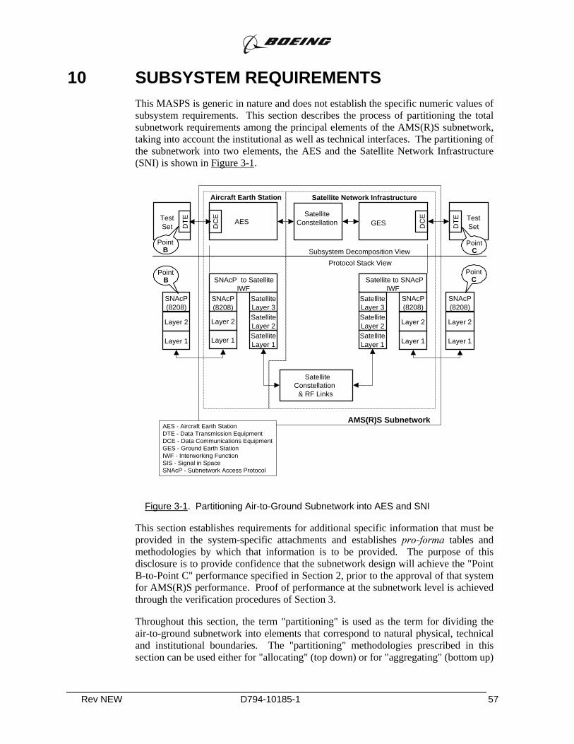
Rev NEW D794-10185-1 57
10 SUBSYSTEM REQUIREMENTS This MASPS is generic in nature and does not establish the specific numeric values of subsystem requirements. This section describes the process of partitioning the total subnetwork requirements among the principal elements of the AMS(R)S subnetwork, taking into account the institutional as well as technical interfaces. The partitioning of the subnetwork into two elements, the AES and the Satellite Network Infrastructure (SNI) is shown in Figure 3-1.
Figure 3-1. Partitioning Air-to-Ground Subnetwork into AES and SNI
This section establishes requirements for additional specific information that must be provided in the system-specific attachments and establishes pro-forma tables and methodologies by which that information is to be provided. The purpose of this disclosure is to provide confidence that the subnetwork design will achieve the "Point B-to-Point C" performance specified in Section 2, prior to the approval of that system for AMS(R)S performance. Proof of performance at the subnetwork level is achieved through the verification procedures of Section 3.
Throughout this section, the term "partitioning" is used as the term for dividing the air-to-ground subnetwork into elements that correspond to natural physical, technical and institutional boundaries. The "partitioning" methodologies prescribed in this section can be used either for "allocating" (top down) or for "aggregating" (bottom up)
Layer 1
Layer 2
SNAcP(8208)
SatelliteLayer 1
SatelliteLayer 2
SatelliteLayer 3
SNAcP to SatelliteIWF
Layer 1
Layer 2
SNAcP(8208)
SatelliteLayer 1
SatelliteLayer 2
SatelliteLayer 3
Satellite to SNAcPIWF
Layer 1
Layer 2
SNAcP(8208)
Layer 1
Layer 2
SNAcP(8208)
Satellite Constellation
& RF Links
AMS(R)S Subnetwork
AESD
CE Satellite
Constellation
Satellite Network Infrastructure
AES - Aircraft Earth StationDTE - Data Transmission EquipmentDCE - Data Communications EquipmentGES - Ground Earth StationIWF - Interworking FunctionSIS - Signal in SpaceSNAcP - Subnetwork Access Protocol
Test Set
DTE GES DC
E Test SetD
TE
Protocol Stack ViewSubsystem Decomposition View
Aircraft Earth Station
PointB
PointB
PointC
PointC
Rev NEW D794-10185-1 58
values of the performance parameters. To avoid unnecessary constraints on subnetwork design, this MASPS does not establish a priori allocations.
Notes: 1. For example, when this MASPS is used as a design guideline in the initial development of an AMS(R)S system, it is anticipated that systems engineers may use the processes called out in this section to assist in balancing performance factors among the individual system elements to achieve optimum subnetwork performance. On the other hand, when an existing MSS system is seeking to qualify for AMS(R)S or AMSS designation by means of this MASPS, this section provides the processes necessary to aggregate the verified performance of individual subsystems and arrive at the comparable AMS(R)S performance for the air-to-ground communications subnetwork as a whole.
2. The partitioning assumes that failures of the AES and SNI components are independent.
10.1 Performance Partitioning Methodologies This section describes methodologies for computing the following aspects of AMS(R)S data link performance: excess link margin, delay, integrity, availability and continuity. The results of these computations shall (70D) be provided in the pro-forma system-specific attachments.
SBB Case Study: Documentation
Some systems may use nonbearing RF links such as control links that can impact AMS(R)S data link performance. For such systems, the following shall (71D) also be provided in the system-specific attachment for each performance-impacting non-bearing link:
a) an excess link margin analysis for the non-bearing link
b) a description of the mechanisms by which the non-bearing link impacts data link performance; and
c) either a technical justification for why the impact of the non-bearing link on the data link performance is insignificant during normal, degraded, and outage stages or a description of the methods used to include the non-data link effects in the performance computations for` the data link performance.
10.1.1 RF Performance
The fundamental determinant of the performance of radio communications systems is the Radio Frequency (RF) link. For any RF link, the achieved signal-to-noise ratio (SNR) determines the quality of the received signal. For radio systems using digital transmission techniques the signal quality is normally expressed in terms of bit error rate (BER), which is related to SNR by well-known formulations. At the external

Rev NEW D794-10185-1 59
interfaces of the air/ground subnetwork, the fundamental BER metric may be used to compute a Residual Block Error Rate. The BER or residual block error rate achieved on a communications link, working in conjunction with the processing design features of the system, directly affects the Installed Communications Performance (ICP) parameters. The performance margin designed into a link⎯ that is, the difference between the actual SNR achieved under nominal conditions and the minimum required SNR⎯ directly affects the probability that the link provides the desired BER or RPER performance. This probability, which is referred to as α in Appendix B, is a consideration in determining the overall system performance.
Each satellite communications system that desires to qualify for the provision of AMS(R)S data shall (72D) provide a detailed analysis to demonstrate that the system design supports performance commensurate with system level requirements of Section 2 and the corresponding Section 2 of the associated system-specific attachment.
SBB Case Study: The raw material for this analysis exists as part of Inmarsat proprietary information
This analysis shall (73D) be presented in the normative part Section 3 of the system-specific attachment document, by means of a set of detailed "link budgets" using the pro-forma analysis methodology described in Appendix B.
SBB Case Study: Documentation
The analysis shall (74D) demonstrate an "excess" system margin, as defined in Appendix B, that is non-negative.
SBB Case Study: The raw material for this analysis exists as part of Inmarsat proprietary information
10.1.2 Transfer Delay Partitioning Methodology
Partitioning of all components of delay performance shall (75C) include the effects of internal subnetwork protocols, if any, used to ensure the integrity of the data blocks crossing the subnetwork interfaces with external subnetworks.
SBB Case Study: The raw material for this analysis exists as part of Inmarsat proprietary information
The effects of higher level protocols implemented by Higher Level Entities external to the subnetwork shall (76C) not be included in the transfer delay calculations.
SBB Case Study: This is a computation requirement tellling us how to perform the analysis
The effects of retransmission to resolve errors in the received data shall (77C) be included in the transfer delay computations.
SBB Case Study: See earlier comments regarding the Gateway and ARQ/HARQ protocols. The raw material for this analysis exists as part of Inmarsat proprietary information. The techniques are discussed in [11-13].

Rev NEW D794-10185-1 60
10.1.2.1 Latency Transfer Delay Component
The latency Transfer Delay component, LATt , shall (78C) be partitioned among the various component subsystems within the AMS(R)S system by means of a simple sum:
( ) ( ) ( )LAT SUBNETWORK LAT AES LAT SISt t t= +
SBB Case Study: This is a computation requirement tellling us how to perform the analysis
10.1.2.2 Mean Transfer Delay
The mean Transfer Delay shall (79C) be partitioned among the constituent elements of the AMS(R)S by means of a simple summation:
( )AMS(R)S components
delay from point B to point C
=d
d k
t E
t
=
∑
SBB Case Study: This is a computation requirement telling us how to perform
the analysis
10.1.2.3 95th Percentile Transfer Delay
Partitioning of the 95th percentile Transfer Delay should be based on convolution of the Transfer Delay distributions for all elements of the link. If the detailed Transfer Delay distribution for any element of the link is not available, partitioning of the 95th percentile Transfer Delay shall (80C) be performed using the methodology detailed in Appendix F. As an alternative to the process of Appendix F, the 95th percentile delay may be partitioned on a simple summation basis. System providers are cautioned that use of this alternate methodology provides an upper bound on the 95th percentile delay and may result in overly severe subsystem requirements.
SBB Case Study: This is a computation requirement telling us how to perform the analysis.
Note: Partitioning of the 95th-percentile transfer delay is a complicated mathematical exercise which requires either a priori knowledge of the distributions of the various elements of the transfer delay or use of simplifying assumptions.
10.1.3 Integrity Methodology
Each AMS(R)S system shall (81D) provide a detailed analysis to demonstrate that the system design supports integrity performance commensurate with system level requirements of Section 2 and its associated system-specific attachment.

Rev NEW D794-10185-1 61
SBB Case Study: Documentation. Some of the integrity performance may have to be assumed by the aeronautical gateway(s).
This analysis shall (82D) be presented in the normative part of a system-specific attachment document, by means of a detailed "fault-tree" using the pro-forma analysis methodology described in Appendix D.
SBB Case Study: This is a computation requirement telling us how to perform the analysis.
All integrity computations shall (83C) be based on a standard block length of 128 octets input at Point B or Point C.
SBB Case Study: This is a computation requirement telling us how to perform the analysis. For SBB, this is a relatively small packet (1 Kbit)
10.1.4 Availability Methodology
Each AMS(R)S system shall (84D) provide a detailed analysis to demonstrate that the system design supports Signal-in-Space availability performance commensurate with system level requirements of Section 2 and its associated system-specific attachment.
SBB Case Study: The raw material for this computation is still Inmarsat proprietary. A sample computation might be possible as part of the final certification report effort.
This analysis shall (85D) be presented in the normative part of a system-specific attachment document, by means of a detailed "fault-tree" using the pro-forma analysis methodology described in Appendix C.
SBB Case Study: This is a computation telling us how to perform the analysis].
10.1.4.1 Methodology for Computing Multi-User Availability
Multi-user Availability shall (86C) be computed based solely on SNI effects, assuming that an operational AES is present for each aircraft and that there exist no single-user interference effects that exceed the ∆T/T allowances in the link budgets.
SBB Case Study: This is a computational requirement telling us how to do the computation. The raw material for this computation is still Inmarsat proprietary.
The pro-forma analysis of the multi-user availability shall (87C) use the following assumptions:
SBB Case Study: This is a computational requirement telling us how to do the computation.

Rev NEW D794-10185-1 62
a) An observation time of one year (8760 operating hours);
b) AMS(R)S users dispersed uniformly throughout the declared service area;
c) Operation with a nominal AES meeting the requirements of the applicable MOPS and operating throughout the observation interval without failure;
d) For the purposes of computing Multi-User Availability, it shall be assumed that a block intended for transmission to one or more aircraft is always present at the terrestrial interface (Point C) of the AMS(R)S subsystem;
e) The Point C interface between the terrestrial subsystem and the AMS(R)S subnetwork shall be assumed to be fixed for the entire observation time; and
f) The external networks interfacing at Point B and Point C are always in a "ready-to-receive" state.
The effects of inter-networking between GES locations shall (88C) not be included in the analysis unless such networking occurs within the boundary of Point C and is performed automatically by the AMS(R)S subnetwork without external user intervention.
SBB Case Study: This is a computational requirement telling us how to do the computation.
Notes: 1. It is possible that operating authorities may require an analysis of multi-user availability based on a subset of the total declared service area. For example, operating authority might be granted based on multi-user availability computed over a specific FIR, or a sector within an FIR. In such cases, it may be appropriate to assume a distribution of user aircraft that is not uniform throughout the area of interest.
2. The term "inter-networking" is used in its most generic sense, and may include both manual and automatic switchover after a catastrophic failure and notification of any such failures to the appropriate higher authority.
10.1.4.2 Methodology for Computing Single User Availability
Single User Availability shall (89C) be computed as the product of the Single-User SNI effects and the availability of the AES function on-board a user aircraft, as determined by the actual intended installation.
SBB Case Study: This is a computational requirement telling us how to do the computation. Availability information regarding the AES function may have to be based on legacy Aero H equipment, as SBB equipment does not exist.
Single User SNI effects shall (90C) include:
Rev NEW D794-10185-1 63
SBB Case Study: This is a computational requirement telling us how to do the computation.
1) multi-user availability, and
2) single-user interference effects that exceed the ∆T/T allowances in the link budgets.
Interference effects shall (91C) include those resulting from pairwise operation in airspace shared with other AMS(R)S equipment of different technologies on a one-to-many basis.
SBB Case Study: This computation may require details about the receivers, or, may impose details on the receivers. It all depends on whether the MOPS follows DO-210D performance, or whether a new MOPS is anticipated.
The pro-forma analysis of the Single-User availability shall (92C) use the following assumptions:
SBB Case Study: This is a computational requirement telling us how to do the computation.
a) an observation time of one year (8760 operating hours) shall be used;
b) The airborne antenna subsystem is considered part of the AES;
c) All supporting avionics and aircraft systems, for example CMU's and power systems, shall be assumed to operate without failure;
d) AMS(R)S users dispersed uniformly throughout the declared service area; and
e) The AMS(R)S user operates in a mixed environment of uniformly distributed interference sources consistent with that environment.
For the purpose of initial submission in the system-specific attachment, the availability of the AES function on-board a user aircraft shall (93C) be assumed to be unity.
SBB Case Study: This is a computational requirement telling us how to do the computation.
Note: The effects of dual dissimilar equipage (i.e., redundant equipment for use with other dissimilar safety communications systems) or redundant equipage for use with the specific technology under discussion are not included in the computation of Single-User Availability for a specific AMS(R)S system because appropriate credit for such equipage will be included in the final determination of the Installed Communications Performance for the specific aircraft installation.

Rev NEW D794-10185-1 64
10.1.5 Continuity Methodology
Each AMS(R)S system shall (95D) provide a detailed analysis to demonstrate that the system design supports Continuity of Service performance commensurate with system level requirements of Section 2 and its associated system-specific attachment.
SBB Case Study: Documentation. The details necessary to perform this analysis are still Inmarsat proprietary.
This analysis shall (96D) be presented by means of a detailed "fault-tree" using the pro-forma analysis methodology described in Appendix C.
SBB Case Study: This is a computational requirement telling us how to do the computation.
10.1.5.1 Methodology for Computing Multi-User Continuity of Service
Multi-user Continuity of Service shall (97C) be computed based solely on SNI effects, assuming that an operational AES is present and that there exist no single-user interference effects that exceed the ∆T/T allowances in the link budgets.
SBB Case Study: This is a computational requirement telling us how to do the computation. Continuity information regarding the AES function may have to be based on legacy Aero H equipment, as SBB equipment does not exist.
The pro-forma analysis of the multi-user Continuity of Service shall (98C) use the following assumptions:
SBB Case Study: This is a computational requirement telling us how to do the computation.
1) AMS(R)S users dispersed uniformly throughout the declared service area.
2) Operation with a nominal AES meeting the requirements of the applicable MOPS and operating throughout the observation interval without failure.
3) For the purposes of computing Multi-User Continuity, it shall be assumed that a block intended for transmission to one or more aircraft is always present at the terrestrial interface (Point C) of the AMS(R)S subsystem.
4) The Point C interface between the terrestrial subsystem and the AMS(R)S subnetwork shall be assumed to be fixed for the entire observation time.
5) The effects of inter-networking between GES locations shall not be included in the analysis unless such networking occurs within the boundary of Point C and is performed automatically by the AMS(R)S subnetwork without external user intervention.
Note: It is possible that operating authorities may require an analysis of multi-user Continuity based on a sub-set of the total declared service area. For example, operating authority might be granted based on multi-user
Rev NEW D794-10185-1 65
availability computed over a specific FIR, or a sector within an FIR. In such cases, it may be appropriate to assume a distribution of user aircraft that is not uniform throughout the area of interest.
10.1.5.2 Methodology for Computing Single User Continuity of Service
Single User Continuity of Service shall (99C) be computed as the product of the Single-User SNI effects and the Continuity of the AES function on-board a user aircraft, as determined by the actual intended installation.
SBB Case Study: This is a computational requirement telling us how to do the computation.
Single User SNI effects shall (100C) include both the multi-user Continuity of Service calculated per Section 3.1.5.1 and the single-user intersystem interference effects that exceed the ∆T/T allowances detailed in Section 3.3.1.2.2.
SBB Case Study: This is a computational requirement telling us how to do the computation. Continuity information regarding the AES function may have to be based on legacy Aero H equipment, as SBB equipment does not exist.
The interference analysis shall (101C) be conducted using scenarios similar to the example provided in Appendix G. In that example, the affected single user operates with the AES equipment described by the system-specific attachment in an airspace environment consisting of multiple aircraft, all of which are operating with the predominant different AMSS system.
SBB Case Study: This is a computational requirement telling us how to do the computation.
The interference analysis shall (102C) include the worst case of these scenarios.
SBB Case Study: This is a documentation requirement telling which of the scenarios to submit.
Notes: 1. The single-user interference effects may result from simultaneous operation of the AMS(R)S equipment described in the system-specific material in airspace shared with other AMS(R)S equipment of different technologies.
2. It is assumed that any intrasystem interference effects do not contribute to single-user service interruptions because of the control that a system operator can exercise over channel assignments to proximate AESs within its own system, in accordance with Section 3.1.2.1.
3. There is no requirement to perform an analysis that includes simultaneous interference from multiple different technologies.
The pro-forma analysis of the Single-User Continuity shall (103C) use the following assumptions:
1) The airborne antenna subsystem is considered part of the AES,
Rev NEW D794-10185-1 66
2) All supporting avionics and aircraft systems, for example CMU's and power systems, shall be assumed to operate without failure,.
3) AMS(R)S users dispersed uniformly throughout the declared service area, and
4) The AMS(R)S user operates in a mixed environment of uniformly distributed interference sources consistent with that environment.
For the purpose of initial submission in the system-specific attachment, the Continuity of the AES function on-board a user aircraft shall (yyC) be assumed to be unity.
SBB Case Study: This is a computational requirement telling us how to do the computation.
Note: The effects of dual dissimilar equipage (i.e., redundant equipment for use with other dissimilar safety communications systems) or redundant equipage for use with the specific technology under discussion are not included in the computation of Single-User Continuity for a specific AMS(R)S system because appropriate credit for such equipage will be included in the final determination of the Installed Communications Performance for the specific aircraft installation.
10.2 AES Subsystem Requirements The AES shall (104F) comply with the requirements of RTCA DO-210D or RTCA DO-262, as appropriate.
SBB Case Study: This is the link between MASPS and MOPS. It anticipates that new MOPS, per DO-262 will be developed for SBB equipment. As of March 2005, RTCA has no plans to develop the technical appendices for either MOPS DO-270 or MASPS DO-262.
The system-specific attachment shall (105C) utilize the minimum performance specified in the applicable MOPS when performing the analyses described in Section 3.1, except in those cases clearly identified as being associated with enhanced performance feature(s) that are also specifically delineated in its MOPS.
SBB Case Study: This is a computational requirement telling us how to do the computation.
Notes : 1. The effects of AES contributions to transfer delay are assumed to be negligible compared to the overall sub-network transfer delay.
2. These requirements differ from top-down systems engineering practice by assuming the existence of lower level MOPS documents prior to completion of this MASPS. While acknowledging this inconsistency, the prior publication of RTCA DO-210D and RTCA DO-262 make this an appropriate practice in this particular case.
Rev NEW D794-10185-1 67
10.3 Satellite Network Infrastructure (SNI) Requirements
10.3.1 SNI Performance Requirements
10.3.1.1 RF Link Performance Requirements
SNI RF Link Performance shall (106D) be partitioned based on the Link Budget analysis required by Section 3.1.1.
SBB Case Study: This is a documentation/systems engineering requirement. The raw material to comply with this requirement exists, but is still Inmarsat proprietary].
10.3.1.2 Mitigation of Harmful Interference
10.3.1.2.1 Intrasystem Interference
Intrasystem interference refers to interference to an AMS(R)S due to any other use of the system; for example, in a satellite communication system that provides both AMS(R)S and non-safety communication services, or a system that provides AMS(R)S and in-band signaling using the same RF spectrum.
Each AMS(R)S system shall (107D) provide in its system- specific attachment a description of how the system design controls intrasystem interference to ensure that the overall system performance requirements are satisfied.
SBB Case Study: This is a documentation/systems engineering requirement. The raw material to comply with this requirement exists, but is still Inmarsat proprietary].
Notes: 1. This can be accomplished by demonstrating that the achieved link 0 0/( )C N I+ (carrier-to-noise-plus-interference-spectral-density ratio) is
not below the required 0/C N times the defined margin in each specific case. Refer to Appendix B for a detailed methodology.
2. Examples of intrasystem interference include co-channel and adjacent channel interference, intermodulation and noise. Because there are disparate satellite communication system designs, there is no single specification for intrasystem interference.
10.3.1.2.2 Intersystem Interference
Intersystem interference refers to interference to an AMS(R)S service from any other system, whether it is providing AMS(R)S services or otherwise.
The system-specific attachment shall (108D) describe how the required performance is maintained for the declared level of susceptibility to interference.
SBB Case Study: This is a requirement to be flowed to the MOPS and the MOPS technical appendices. Some of the raw material to comply with this
Rev NEW D794-10185-1 68
requirement exists, but is still Inmarsat proprietary. Other raw material will depend on the equipment manufacturers.
The system-specific attachment shall (109D) provide a description of how the system provides adequate performance in the presence of an aggregate interference level from all external sources equal to 25% of the total noise power in the received RF channel, and the single-entry interference level of 6% of the total noise power in the received RF channel.18
SBB Case Study: This is a documentation/systems engineering requirement. The raw material to comply with this requirement exists, but is still Inmarsat proprietary. Recent FCC rulings (FCC 05-30) may affect both the quantitative and qualitative elements of this requirement.
Notes: 1. The effects of increased interference levels can usually be mitigated by power control. An increase in interference from an external system will increase the power required on a per-channel basis to meet the C/N0 requirement for the RF link. There is a likely economic impact associated with this strategy of interference management.
2. For example, if the system noise power plus intrasystem interference is 151 10 W−× , the system must tolerate additional aggregate external
interference of at least 15 1525% (1 10 W) = 0.25 10 W− −× × × . The total noise power plus intrasystem interference power plus intersystem interference power is thus 151.25 10 W−× .
10.3.1.3 Network Coordination and Control Function
The Network Coordination and Control Function (NCCF) performs administrative and technical management functions for a satellite communication system. Only those functions essential to the provision of AMS(R)S need be identified.
Notes: 1. As used in this MASPS, coordination includes the processes of intersystem coordination as described in ITU and National Radio Regulations. Coordination activities include those additional intrasystem and intersystem processes that are necessary to support system management functions related to long-term institutional arrangements.
2. Intersystem coordination is required among the several possible satellite communication systems throughout the world that may support or have impact on AMS(R)S services.
3. This Section does not require that the Network Control functions be allocated to specific subsystems (e.g., a Network Coordination Center or GESs) in any particular way.
18 This requirement is in accordance with ITU Recommendation M.1234.

Rev NEW D794-10185-1 69
10.3.1.3.1 Intrasystem Coordination
The system-specific attachment shall (110D) provide a description of the intrasystem coordination functions, such as:
SBB Case Study: Documentation. This information is still Inmarsat proprietary.
1) Access control for mobile earth stations (MESs), including AESs, and GESs; with means to deny access for MESs that cause failure of the satellite communication system to meet the requirements of this MASPS in any way;
2) Monitoring and verification of correct operation of system components (e.g., equipment, terminals, earth stations, satellites) and provision of mechanisms for disabling aberrant system components, including MESs;
3) Management of information supplied to MESs to assist in their acquisition of satellite communication system resources (e.g., satellite orbital positions, operational frequencies and/or time slots, geolocation parameters);
4) Management of frequency assignments;
5) Management of identities and service requests;
6) Control of mechanisms governing assignment and use of system resources supporting priority and preemption;
7) Infrastructure and procedures for control of acceptance, subsequent maintenance, and verification of system components.
10.3.1.3.2 Intersystem Coordination: Same Frequency Band, Same Protocols
Note: Intersystem coordination involves the real-time and longer-term functions requiring the exchange of information among individual satellite communication systems providing AMS(R)S services.
The system-specific attachment shall (111D) provide a description of the intersystem coordination functions, such as:
SBB Case Study: Documentation. This information is still Inmarsat proprietary.
1) Maintenance of data for MES and GES coordination tables (the elements within the satellite communication system responsible for coordination shall maintain appropriate tables of system information);
2) "Seamless" and user-transparent handoff of AESs from one satellite to the next;
3) Communication of MES availability and status with other subsystems;
4) Accommodation of user selection of the satellite operator or service provider of the user’s choice;
Rev NEW D794-10185-1 70
5) Cooperative procedures for mitigating harmful interference and the provision of backup satellite resources;
6) Management of connectivity with contiguous subsystems and the protocol structures involved.
10.3.1.3.3 Intersystem Coordination: Different Frequency Bands
The system-specific attachment shall (112D) provide a description for the cooperative procedures for mitigating harmful interference from other external systems.
SBB Case Study: Documentation. This information will be dependent on the content of the MOPS, as well on satellite and ground segment details. These details exist, but remain Inmarsat proprietary.
10.3.1.3.4 Intersystem Coordination: Same Frequency Band, Different Protocols
The system-specific attachment shall (113D) provide a description for the cooperative procedures for mitigating harmful interference from external systems that operate in same frequency band(s), but with different protocols and/or multiple access methods.
SBB Case Study: SBB will undergo the same spectrum coordination process currently used for Aero H and other legacy systems.
10.3.2 SNI Functional Requirements
The GES shall (114D) provide packet-mode interfaces with the terrestrial subsystem shown in Figure 1-2.
SBB Case Study: SBB is primarily a packet service, and complies with this requirement.
GES terrestrial packet-mode interfaces shall (115F) comply with an internationally recognized standard interface. An example of such an international standard is ISO-8208, but other standards are permissible.
SBB Case Study: SBB is primarily a packet service, and complies with this requirement.
The system-specific attachment shall (116D) provide a full description of the interfaces.
SBB Case Study: Documentation.
REFERENCES:
[1] "Minimum Operational Performance Standards for Avionics Supporting Next Generation Satellite Systems (NGSS)," RTCA, Inc., 2000.
[2] "Minimum Aviation System Performance Standards for Aeronautical Mobile Satellite (Route) Services (AMS(R)S)," RTCA, Inc., Washington, D.C., DO-270, 2001.
[3] "High-Density 2015 European Traffic Distributions for Simulation, ver 1.2," EUROCONTROL ADS Programme, Brussels, BE, March 23, 2000.
[4] "Operating Concept of the Mobile Aviation Communication Infrastructure Supporting ATM beyond 2015, WP2 - Operating Concept for the future mobile communication infrastructure," Eurocontrol, Brussels, D2 v1a, 5 July, 2002.
[5] E. F. C. LaBerge, "Explanation of MACONDO Traffic Load Extensions," Honeywell CST CoE, Columbia, MD, CSTCOE-EFCL-210C, 29 Sept, 2004.
[6] E. F. C. LaBerge, "Analysis if DO-210D AES Emissions with Volumetric Model on North Atlantic Routes," RTCA, Inc, Washington, DC, SC165/WG1-WP/439, February 12, 2000.
[7] E. F. C. LaBerge, "Volumetric Interference Analysis," RTCA Special Committee 165, Working Group 1, SC165/WG1-WP438B, Feb. 15, 2000.
[8] E. F. C. LaBerge, "Update of North Atlantic Volumetric Model," RTCA Special Committee 165, Working Group 3, SC165/WG3-WP/623, March, 2000.
[9] E. F. C. LaBerge, "Update of North Atlantic Volumetric Model with Proposed Revision to Inmarsat HSN Values," RTCA, Inc, Washington, DC, SC165/WG1-WP/448, February 15, 2000.
[10] E. F. C. LaBerge, "A Volumetric Model for Assessing Interference Between SATCOM-equipped Aircraft in the Same Airspace," RTCA Special Committee 165, Working Group 3, SC165/WG3-WP/678, March, 2001.
[11] S. Wicker, Error Control Systems for Digital Communication and Storage. Upper Saddle River, NJ: Prentice Hall, 1994.
[12] E. F. C. LaBerge, On Turbo-Coded Hybrid ARQ Techniques Constrained by Time-Division Multiplex Signal Formats, PhD Dissertation, University of Maryland, Baltimore County, Baltimore, MD, 2003.
[13] E. F. C. LaBerge and J. M. Morris, "Expressions for the Mean Transfer Delay of Generalized M-Stage Hybrid ARQ Protocols", IEEE Transactions on Communications, vol. 52, no. 6, pp. <tbd>, June, 2004.