m67001.ar.005158 mcb camp lejeune 5090€¦ · m67001.ar.005158 mcb camp lejeune 5090.3a final...
TRANSCRIPT

M67001.AR.005158MCB CAMP LEJEUNE
5090.3a
FINAL SAMPLING AND ANALYSIS PLAN FOR HISTORIC METALS EVALUATIONOPERABLE UNITS 1 AND 2 (OU1) (OU2) MCB CAMP LEJEUNE NC
8/3/2012CH2M HILL

SAMPLING AND ANALYSIS PLAN – HISTORICAL METALS EVALUATION OPERABLE UNITS 1 AND 2 REVISION NUMBER 0 JUNE 2012 PAGE 2 OF 100
This page intentionally left blank.

SAMPLING AND ANALYSIS PLAN – HISTORICAL METALS EVALUATION OPERABLE UNITS 1 AND 2 REVISION NUMBER 0 JUNE 2012 PAGE 4 OF 100
This page intentionally left blank.

SAMPLING AND ANALYSIS PLAN – HISTORICAL METALS EVALUATION OPERABLE UNITS 1 AND 2 REVISION NUMBER 0
JUNE 2012 PAGE 5 OF 100
Executive Summary
This document presents the Uniform Federal Policy (UFP) Sampling and Analysis Plan (SAP) to conduct additional investigation activities in support of a historical metals evaluation in groundwater at Operable Unit (OU) 1 (Site 78) and OU 2 (Sites 6 and 82), Marine Corps Base Camp Lejeune (MCB CamLej), North Carolina.
CH2M HILL prepared this document under the United States (U.S.) Department of the Navy (Navy), Naval Facilities Engineering Command (NAVFAC) Mid-Atlantic Division, Comprehensive Long-Term Environmental Action - Navy (CLEAN) 8012 Contract N62470-11-D-8012, Contract Task Order (CTO) WE21, in accordance with the Navy’s UFP-SAP policy guidance to ensure that environmental data collected are scientifically sound, of known and documented quality, and suitable for intended uses. The Master Project Plans for Marine Corps Base Camp Lejeune (CH2M HILL, 2008) and the Site Management Plan, Fiscal Year 2012, Marine Corps Base Camp Lejeune, Jacksonville, North Carolina (CH2M HILL, 2011c) provide additional information and background on MCB CamLej.
The purpose of this investigation is to address recommendations from the Five-Year Comprehensive Environmental Response, Compensation, and Liability Act of 1980 (CERCLA) Review (Five-Year Review) completed in August 2010 (CH2M HILL, 2010). Current remedies at MCB CamLej were evaluated to determine whether the remedies remain protective of human health and the environment, as outlined in the Record of Decision (ROD) or Action Memorandum. One of the recommendations in the Five-Year Review included reassessing metals as contaminants of concern (COCs) in groundwater at OU 1 and OU 2. Select metals are currently listed as COCs in the RODs but are not included in the long-term monitoring (LTM) program at the two OUs for the following reasons:
• OU 1 – remedial goals at the time were not exceeded in 4 rounds of sampling (1997)
• OU 2 – there was no historical evidence of metal disposal and remedial goals were consistent with or below natural background concentrations
From the time the RODs were signed, regulatory standards for metals have become more conservative, post-ROD investigations have revealed new information about potential metals contamination at OU 2 (including metals not listed as COCs in the ROD), and an expanded Basewide background study of metals in groundwater has been completed. Consequently, the Five-Year Review recommended the following activities at OU 1 and OU 2:
• Collect groundwater samples from wells in the LTM program that provide spatial and vertical distribution throughout the OUs for total metals analysis.
• Compare to current remedial goals and updated background concentrations to evaluate whether any detected concentrations exceeding remedial goals are site-related or attributable to background.
• If there are no exceedances of remedial goals or metals that exceed remedial goals are not considered site-related, prepare an Explanation of Significant Differences (ESD) to remove metals as COCs.
• If metals that exceed remedial goals are considered site-related, evaluate risks, add metals COCs to LTM Program, evaluate LUCs, and prepare an ESD.
SAP Outline This UFP-SAP consists of 37 worksheets specific to the scope of work for the historical metals evaluation at OU1 and OU2. All tables are embedded within the worksheets. All figures are included at the end of the document. The project-specific Health and Safety Plan (HASP) is included as Attachment 1. Field standard operation procedures (SOPs) are included in Attachment 2. Data management guidelines are included in Attachment 3, and laboratory

SAMPLING AND ANALYSIS PLAN – HISTORICAL METALS EVALUATION OPERABLE UNITS 1 AND 2 REVISION NUMBER 0 JUNE 2012 PAGE 6 OF 100
Department of Defense (DoD) Environmental Laboratory Accreditation Program (ELAP) letters are included in Attachment 4. Upon approval of this Draft SAP, the sampling activities will be scheduled and executed.

SAMPLING AND ANALYSIS PLAN – HISTORICAL METALS EVALUATION OPERABLE UNITS 1 AND 2 REVISION NUMBER 0
JUNE 2012 PAGE 7 OF 100
SAP Worksheets
SAP Worksheet #1—Title and Approval Page................................................................................................................ 1
SAP Worksheet #2—SAP Identifying Information ....................................................................................................... 13
SAP Worksheet #3—Distribution List .......................................................................................................................... 15
SAP Worksheet #4—Project Personnel Sign-Off Sheet ............................................................................................... 17
SAP Worksheet #5—Project Organizational Chart ...................................................................................................... 19
SAP Worksheet #6—Communication Pathways .......................................................................................................... 21
SAP Worksheet #7—Personnel Responsibilities Table ................................................................................................ 23
SAP Worksheet #8—Special Personnel Training Requirements Table ........................................................................ 25
SAP Worksheet #9-1—Project Scoping Session Participation Sheet ........................................................................... 27
SAP Worksheet #9-2—Project Scoping Session Participation Sheet ........................................................................... 28
SAP Worksheet #10—Problem Definition ................................................................................................................... 29
SAP Worksheet #11—Project Quality Objectives/Systematic Planning Process Statements ..................................... 35
SAP Worksheet #12-1—Measurement Performance Criteria Table—Field QC Samples ............................................ 39
SAP Worksheet #12-2—Measurement Performance Criteria Table—Field QC Samples ............................................ 40
SAP Worksheet #13—Secondary Data Criteria and Limitations Table ........................................................................ 41
SAP Worksheet #14—Summary of Project Tasks ........................................................................................................ 43
SAP Worksheet #15-1—Reference Limits and Evaluation Table ................................................................................. 47
SAP Worksheet #15-2—Reference Limits and Evaluation Table ................................................................................. 48
SAP Worksheet #16—Project Schedule / Timeline Table ............................................................................................ 49
SAP Worksheet #17—Sampling Design and Rationale ................................................................................................ 51
SAP Worksheet #18—Sampling Locations and Methods/SOP Requirements Table ................................................... 53
SAP Worksheet #18—Sampling Locations and Methods/SOP Requirements Table (continued) ............................... 56
SAP Worksheet #19—Analytical SOP Requirements Table ......................................................................................... 59
SAP Worksheet #20—Field Quality Control Sample Summary Table .......................................................................... 61
SAP Worksheet #21—Project Sampling SOP References Table .................................................................................. 63
SAP Worksheet #22—Field Equipment Calibration, Maintenance, Testing, and Inspection Table ............................ 65
SAP Worksheet #23—Analytical SOP References Table .............................................................................................. 67
SAP Worksheet #24—Analytical Instrument Calibration Table ................................................................................... 69
SAP Worksheet #25—Analytical Instrument and Equipment Maintenance, Testing, and Inspection Table .............. 71

SAMPLING AND ANALYSIS PLAN – HISTORICAL METALS EVALUATION OPERABLE UNITS 1 AND 2 REVISION NUMBER 0 JUNE 2012 PAGE 8 OF 100
SAP Worksheet #26—Sample Handling System .......................................................................................................... 73
SAP Worksheet #27—Sample Custody Requirements ................................................................................................ 75
SAP Worksheet #28-1—Laboratory QC Samples Table ............................................................................................... 77
SAP Worksheet #28-2—Laboratory QC Samples Table ............................................................................................... 78
SAP Worksheet #29—Project Documents and Records Table .................................................................................... 79
SAP Worksheet #30—Analytical Services Table .......................................................................................................... 81
SAP Worksheet #31—Planned Project Assessments Table ......................................................................................... 83
SAP Worksheet #32—Assessment Findings and Corrective Action Responses .......................................................... 85
SAP Worksheet #32-1—Corrective Action Form ......................................................................................................... 87
SAP Worksheet #32-2—Field Performance Audit Checklist ........................................................................................ 89
SAP Worksheet #33—QA Management Reports Table ............................................................................................... 91
SAP Worksheets #34-36—Data Verification and Validation (Steps I and IIa/IIb) Process Table ................................. 93
SAP Worksheet #37—Usability Assessment ................................................................................................................ 97
Attachments
1 Site Health and Safety Plan 2 Standard Operating Procedures—CH2M HILL 3 Data Management Guidelines 4 DoD ELAP Accreditation Letter – Analytical Laboratories 5 Response to Comments Letter
Figures
10-1 Operable Unit Location Map 10-2 OU 1 Map 10-3 OU 2 Map

SAMPLING AND ANALYSIS PLAN – HISTORICAL METALS EVALUATION OPERABLE UNITS 1 AND 2 REVISION NUMBER 0
JUNE 2012 PAGE 9 OF 100
Acronyms and Abbreviations
°C degree Celsius µg/L microgram per liter %R percent recovery
AM Activity Manager amsl above mean sea level amu atomic mass unit AQM Activity Quality Manager
Baker Baker Environmental, Inc. BBLPS behavior based loss prevention system bgs below ground surface
CA Corrective Action CAS Chemical Abstract Service CCV continuing calibration verification CERCLA Comprehensive Environmental Response, Compensation, and Liability Act of 1980 CLEAN Comprehensive Long-Term Environmental Action - Navy COC contaminant of concern COPC contaminant of potential concern CS Confirmation Study CTO Contract Task Order CVAA cold vapor atomic absorption
DL detection limit DoD Department of Defense DQI Data Quality Indicator DRMO Defense Reutilization and Marketing Office
ELAP Environmental Laboratory Accreditation Program EMD Environmental Management Division EPA United States Environmental Protection Agency ESD Explanation of Significant Differences
FTL Field Team Leader FY Fiscal Year
H&S Health and Safety HASP Health and Safety Plan HHRA Human Health Risk Assessment HHRS Human Health Risk Screening HPFF Hadnot Point Fuel Farm HPIA Hadnot Point Industrial Area
ICAL initial calibration ICP inductively coupled plasma ICS interference check solution ICV initial calibration verification ID identification IDW investigation-derived waste IRA Interim Remedial Action

SAMPLING AND ANALYSIS PLAN – HISTORICAL METALS EVALUATION OPERABLE UNITS 1 AND 2 REVISION NUMBER 0 JUNE 2012 PAGE 10 OF 100
ISTD internal standard
LCS laboratory control sample LF/WV low flow/well volume LOD limit of detection LOQ limit of quantitation LTM long-term monitoring LUC land use control
MCB CamLej Marine Corps Base Camp Lejeune MCL maximum contaminant level ml milliliter MPPEH material potentially presenting an explosive hazard MR Munitions Response MS matrix spike; mass spectrometer MSD matrix spike duplicate
NA not applicable NAVFAC Naval Facilities Engineering Command Navy Department of the Navy NC no criteria NCDENR North Carolina Department of Environment and Natural Resources NCGWQS North Carolina Groundwater Quality Standards NTR Navy Technical Representative
OHM OHM Remediation Services Corporation ORP oxidation-reduction potential OU Operable Unit
PAL project action limit PCB polychlorinated biphenyl PDM Project Data Manager PE Professional Engineer PG Professional Geologist PID photoionization detector PM Project Manager POC point of contact PQL Project Quantitation Limit PQO project quality objective PS post spike
QA quality assurance QAM Quality Assurance Manager QAMS Quality Assurance Management Staff QAO Quality Assurance Officer QAPP Quality Assurance Project Plan QC quality control QSM Quality Systems Manual
RI Remedial Investigation RIP Remedy in Place RL reporting limit ROD Record of Decision RPD relative percent difference

SAMPLING AND ANALYSIS PLAN – HISTORICAL METALS EVALUATION OPERABLE UNITS 1 AND 2 REVISION NUMBER 0
JUNE 2012 PAGE 11 OF 100
RPM Remedial Project Manager RSD relative standard deviation RSL Regional Screening Level
SAP Sampling and Analysis Plan SOP standard operating procedure SSC site safety coordinator STC Senior Technical Consultant SVOC semi-volatile organic compound
TAL target analyte list TBD to be determined
U.S. United States UFP Uniform Federal Policy USMC United States Marine Corps UST underground storage tank UV ultraviolet UXO unexploded ordnance
VIS visual spectroscopy VOC volatile organic compound
WQP water quality parameter

SAMPLING AND ANALYSIS PLAN – HISTORICAL METALS EVALUATION OPERABLE UNITS 1 AND 2 REVISION NUMBER 0 JUNE 2012 PAGE 12 OF 100
This page intentionally left blank.

SAMPLING AND ANALYSIS PLAN – HISTORICAL METALS EVALUATION OPERABLE UNITS 1 AND 2 REVISION NUMBER 0
JUNE 2012 PAGE 13 OF 100
SAP Worksheet #2—SAP Identifying Information
Site Name/Number: Site 78, Site 6, Site 82
Operable Unit (OU): 1 and 2
Contractor Name: CH2M HILL
Contract Number: N62470-11-D-8012
Contract Title: Comprehensive Long-Term Environmental Action - Navy (CLEAN) 8012
Work Assignment Number (optional):
1. This Sampling and Analysis Plan (SAP) was prepared in accordance with the requirements of:
Guidance for Quality Assurance Project Plans (QAPPs) (EPA, 2002)
Quality Assurance (QA)/G-5, Quality Assurance Management Staff (QAMS) (EPA, 2002)
Intergovernmental Data Quality Task Force Uniform Federal Policy for Quality Assurance Plans (UFP-QAPP) (EPA, 2005)
Guidance on Systematic Planning Using the Data Quality Objectives Process (EPA, 2006)
2. Identify regulatory program: Comprehensive Environmental Response, Compensation, and Liability Act of 1980 (CERCLA)
3. This SAP is a Project-Specific SAP
4. List dates of scoping sessions that were held:
Scoping Session Date
Partnering Meeting August 17, 2010
Partnering Meeting August 16, 2011

SAMPLING AND ANALYSIS PLAN – HISTORICAL METALS EVALUATION OPERABLE UNITS 1 AND 2 REVISION NUMBER 0 JUNE 2012 PAGE 14 OF 100
SAP Worksheet #2—SAP Identifying Information (continued)
5. List dates and titles of any SAP documents written for previous site work that are relevant to the current investigation.
Title Date
Long-term Monitoring Sampling and Analysis Plan, Sites 3, 6 and 82, 35, 36, 73, 78, and 93, Marine Corps Base Camp Lejeune, Jacksonville, North Carolina
November 2009
Long-term Monitoring Sampling and Analysis Plan, Sites 3, 6 and 82, 35, 36, 73, 78, and 93, Marine Corps Base Camp Lejeune, Jacksonville, North Carolina
November 2010
6. List organizational partners (stakeholders) and connection with lead organization:
− North Carolina Department of Environment and Natural Resources (NCDENR) (regulatory stakeholder)
− United States (U.S.) Environmental Protection Agency (EPA) Region 4 (regulatory stakeholder)
− Naval Facilities Engineering Command (NAVFAC) Mid-Atlantic (lead organization)
− Marine Corps Base Camp Lejeune (MCB CamLej)
7. Lead organization:
U.S. Department of the Navy (Navy) – Lead Agency
8. If any required SAP elements or required information are not applicable (NA) to the project or are provided elsewhere, then note the omitted SAP elements and provide an explanation for their exclusion below:
Crosswalk table is excluded because all required information is provided in this SAP.

SAMPLING AND ANALYSIS PLAN – HISTORICAL METALS EVALUATION OPERABLE UNITS 1 AND 2 REVISION NUMBER 0
JUNE 2012 PAGE 15 OF 100
SAP Worksheet #3—Distribution List
Name of SAP Recipients Title/Role Organization Telephone Number E-mail Address or Mailing Address
Dave Cleland Navy Technical Representative (NTR) NAVFAC Mid-Atlantic (757) 322-4851 [email protected]
Charity Rychak Environmental Engineer MCB CamLej- Environmental Management Division (EMD) (910) 451-9385 [email protected]
Gena Townsend Remedial Project Manager (RPM) EPA Region 4 (404) 562-8538 [email protected]
Randy McElveen RPM NCDENR (919) 707-8341 [email protected]
Matt Louth Activity Manager (AM)
CH2M HILL
(757) 671-6240 [email protected]
Chris Bozzini Activity Quality Manager (AQM) (704) 544-5163 [email protected]
Tegwyn Williams Senior Technical Consultant (STC) (704) 543-3297 [email protected]
Kristin Rogers Project Manager (PM) (919) 760-1789
Brett Doerr
Navy CLEAN Program UFP-SAP Reviewer (757) 671-6219
Carl Woods
Health and Safety (H&S) Manager (513) 889-5771
Anita Dodson
Navy CLEAN Program Chemist (757)671-6218 [email protected]
To Be Determined (TBD) Field Team Leader (FTL) TBD TBD
Bianca Kleist Project Chemist (704) 543-3274 [email protected]
Troy Horn Project Data Manager (PDM) (757) 671-6288 [email protected]
Ronnie Wambles Laboratory/PM ENCO (407) 826-5314 [email protected]
Lori Mangrum Laboratory Quality Assurance Officer (QAO) ENCO (407) 826-5314 [email protected]
Laura Maschhoff Data Validator DataQual Environmental Services (314) 330-1327 [email protected]

SAMPLING AND ANALYSIS PLAN – HISTORICAL METALS EVALUATION OPERABLE UNITS 1 AND 2 REVISION NUMBER 0 JUNE 2012 PAGE 16 OF 100
This page intentionally left blank.

SAMPLING AND ANALYSIS PLAN – HISTORICAL METALS EVALUATION OPERABLE UNITS 1 AND 2 REVISION NUMBER 0
JUNE 2012 PAGE 17 OF 100
SAP Worksheet #4—Project Personnel Sign-Off Sheet
Name Organization/Title/Role Telephone Number Signature/ email
receipt Section Reviewed Date SAP Read
Dave Cleland NAVFAC-Mid Atlantic/ NTR (757) 322-4851
Charity Rychak MCB CamLej/ EMD/Environmental Engineer (910) 451-9385
Gena Townsend EPA Region 4/ RPM (404) 562-8538
Randy McElveen NCDENR/ RPM (919) 707-8341
Matt Louth CH2M HILL/ AM (757) 671-6240
Brett Doerr CH2M HILL/Navy CLEAN Program UFP-SAP Reviewer (757) 671-6219
Kristin Rogers CH2M HILL/ PM (919) 760-1789
Chris Bozzini CH2M HILL/ AQM (704) 543-5163
Tegwyn Williams CH2M HILL/ STC (704) 543-3297
Carl Woods CH2M HILL/ H&S Manager (513) 889-5771
Anita Dodson CH2M HILL/Navy CLEAN Program Chemist (757)671-6218
Bianca Kleist CH2M HILL/Project Chemist (704) 543-3274
TBD CH2M HILL/ /FTL
Troy Horn CH2M HILL/ PDM (757) 671-6288
Ronnie Wambles ENCO/Lab PM (407) 826-5314
Lori Mangrum Laboratory QAO (407) 826-5314
Laura Maschhoff DataQual/ Data Validator (314) 330-1327
Note:
Final documentation of the completed signature page will be maintained by CH2M HILL in the Charlotte, North Carolina, office.

SAMPLING AND ANALYSIS PLAN – HISTORICAL METALS EVALUATION OPERABLE UNITS 1 AND 2 REVISION NUMBER 0 JUNE 2012 PAGE 18 OF 100
This page intentionally left blank.

SAMPLING AND ANALYSIS PLAN – HISTORICAL METALS EVALUATION OPERABLE UNITS 1 AND 2 REVISION NUMBER 0
JUNE 2012 PAGE 19 OF 100
SAP Worksheet #5—Project Organizational Chart
PM Kristin Rogers – CH2M HILL
(919-760-1789)
Lead Organization Dave Cleland - NAVFAC Mid- Atlantic (757-
322-4851) Lead Organization Chemist/QAO
Jan Nielson - NAVFAC LANT (757- 322- 8339)
AM Matt Louth - CH2M HILL
(757- 671- 6240)
Navy CLEAN Program Chemist Anita Dodson – CH2M HILL
(757- 671- 6218)
Project Chemist Bianca Kleist – CH2M HILL
(704-543-3274)
AQM Chris Bozzini – CH2M HILL
(704- 554-5163)
Laboratory Ronnie Wambles - ENCO-Orlando
(407-826-5314) Data Validation
Laura Maschhoff – DataQual Environmental Services
(314-330-1327)
FTL Onsite H&S Officer
TBD– CH2M HILL ()
PDM Troy Horn – CH2M HILL
(757-671-6288)
H&S Manager Carl Woods – CH2M HILL
(513- 889- 5771)
NAVFAC Customer Charity Rychak - MCB CamLej
(910- 451- 9385)
Regulator and Stakeholder Agencies
Gena Townsend - EPA Region 4 (404- 562– 8538)
Randy McElveen - NCDENR (919-707-8341)
STC Tegwyn Williams – CH2M HILL
(704-534-3297)

SAMPLING AND ANALYSIS PLAN – HISTORICAL METALS EVALUATION OPERABLE UNITS 1 AND 2 REVISION NUMBER 0 JUNE 2012 PAGE 20 OF 100
This page intentionally left blank.

SAMPLING AND ANALYSIS PLAN – HISTORICAL METALS EVALUATION OPERABLE UNITS 1 AND 2 REVISION NUMBER 0
JUNE 2012 PAGE 21 OF 100
SAP Worksheet #6—Communication Pathways
Communication Drivers Responsible Affiliation Name
Phone Number and/or e-mail Procedure, Pathway, etc.
Communication with Navy (lead agency)
Navy NTR/RPM Dave Cleland [email protected] Primary point of contact (POC) for Navy; can delegate communication to other internal or external POCs. RPM will notify EPA and NCDENR via email or telephone call within 24 hours if field changes affecting the scope occur. Navy will have 10 days for work plan review. All sampling data will be presented and discussed during partnering meetings.
Communication with EPA Region 4
EPA Region 4 RPM Gena Townsend [email protected] Primary POC for EPA; can delegate communication to other internal or external POCs. Upon notification of field changes, EPA will have 24 hours to approve or comment on the field changes. All data results will be presented and discussed during partnering meetings.
Communication with NCDENR
NCDENR RPM Randy McElveen [email protected] Primary POC for NCDENR; can delegate communication to other internal or external POCs. Upon notification of field changes, NCDENR will have 24 hours to approve or comment on the field changes.
Communication regarding overall project status and implementation and primary POC with Navy RPM, EPA, and NCDENR
CH2M HILL AM Matt Louth [email protected] Oversees project and will be informed of project status by the PM. If field changes occur, AM will work with the Navy RPM to communicate field changes to the team via email within 24 hours. All data results will be communicated to the project team during the first partnering meeting following data receipt.
Technical communications for project implementation, and data interpretation
CH2M HILL STC Tegwyn Williams [email protected] POC regarding quality questions/issues encountered in the field, input on data interpretation, as needed. STC will have 24 hours to respond to technical field questions as necessary. Additionally, STC will review the data as necessary prior to partnering team discussion and reporting review.
Communications regarding project management and implementation
PM Kristin Rogers [email protected] POC for field sampling team. All information and materials about the project will be forwarded to the Navy, AM, and STC as necessary. Responsible for field team members’ and subcontractors adherence to work plan.
Coordinate activities between PM and field team / subcontractors. Work plan changes in field. QAPP field changes/ field progress reports
FTL TBD TBD Will provide documentation of field activities and work plan or QAPP deviations (made only with approval of the AM and/or QAO in field logbooks; will provide daily progress updates to PM. All field team and reporting activities will be forwarded to PM for further dissemination if necessary.

SAMPLING AND ANALYSIS PLAN – HISTORICAL METALS EVALUATION OPERABLE UNITS 1 AND 2 REVISION NUMBER 0 JUNE 2012 PAGE 22 OF 100
SAP Worksheet #6—Communication Pathways (continued)
Communication Drivers
Responsible Affiliation Name Phone Number and/or e-mail Procedure, Pathway, etc.
H&S Onsite H&S Officer TBD TBD Responsible for field team members’ adherence to the site safety requirements described in the Health and Safety Plan (HASP). Will report H&S incidents and near losses to PM.
Data tracking from field collection to database upload
PDM Troy Horn [email protected] Tracking data from sample collection through database upload.
Reporting lab data quality issues Laboratory QAO
(ENCO)
Lori Mangrum [email protected]
All QA/quality control (QC) issues with project field samples will be reported within 2 days to the project chemist by the laboratory.
Reporting data validation issues
DataQual Environmental Services
Laura Maschhoff
[email protected] All data validation issues regarding resubmissions from the laboratory will copy the CH2M HILL PDM on communications. The data validation report will be due to CH2M HILL within 14 calendar days of data receipt.
Field and analytical Corrective Actions (CAs)
Project Chemist Bianca Kleist [email protected] Any CAs for field and analytical issues will be determined by the FTL and/or the Project Chemist and reported to the PM within 4 hours.
Release of Analytical Data
Navy CLEAN Program Chemist/Project Chemist
Anita Dodson [email protected] No analytical data can be released until validation of the data is completed and has been approved by the Project Chemist. The project chemist will review analytical results within 7 days of receipt for release to the project team. The project chemist will immediately notify the PM, Navy RPM, and Navy QAO of any data quality issues that might cause the project quality objectives (PQOs) to not be obtained. The PM and RPM shall also be notified is there are significant delays by the laboratory that would cause significant project delivery issues.
Field CAs PM Kristin Rogers [email protected] Field and analytical issues requiring CA will be determined by the PM; the PM will ensure QAPP requirements are met by the field staff.

SAMPLING AND ANALYSIS PLAN – HISTORICAL METALS EVALUATION OPERABLE UNITS 1 AND 2 REVISION NUMBER 0
JUNE 2012 PAGE 23 OF 100
SAP Worksheet #7—Personnel Responsibilities Table
Name Title/Role Organizational Affiliation Responsibilities
Dave Cleland, Professional Geologist (PG)
NTR NAVFAC Mid-Atlantic Oversees project
Charity Rychak Environmental Engineer MCB CamLej/EMD Oversees project
Matt Louth, PG AM CH2M HILL Oversees project activities
Kristin Rogers, Professional Engineer (PE)
PM CH2M HILL Manages project and coordinates project tasks and project staff
Brett Doerr Navy CLEAN Program UFP-SAP Reviewer
CH2M HILL Navy CLEAN Program UFP-SAP Reviewer
Chris Bozzini, PE AQM CH2M HILL Manages activity quality
Tegwyn Williams, PG STC CH2M HILL Provides technical oversight and review of technical work products and approaches
Carl Woods H&S Manager CH2M HILL Prepares HASP; manages H&S for all field activities
TBD FTL CH2M HILL Manages project tasks in the field
Anita Dodson Navy CLEAN Program Chemist CH2M HILL Program-level review of UFP-SAP and Program Chemist
Bianca Kleist Project Chemist CH2M HILL Project chemist, coordinates with laboratory and data validator
Troy Horn PDM CH2M HILL Data Management: manages sample tracking, communicates with laboratory and data validator
Ronnie Wambles Laboratory Subcontractor PM ENCO-Orlando Manages samples tracking and maintains good communication with Project Chemist and PDM
Lori Mangrum Laboratory QAO ENCO Responsible for audits, CAs, checks of QA performance within the laboratory.
Laura Maschhoff Data Validator Subcontractor DataQual Validate data received from laboratory prior to use
1 Resumes are maintained by the individuals’ organizations and are available upon request; upon execution of the project, staff members may be removed (if unnecessary to project execution), and other staff members may be added or substituted, as necessary and available.

SAMPLING AND ANALYSIS PLAN – HISTORICAL METALS EVALUATION OPERABLE UNITS 1 AND 2 REVISION NUMBER 0 JUNE 2012 PAGE 24 OF 100
This page intentionally left blank.

SAMPLING AND ANALYSIS PLAN – HISTORICAL METALS EVALUATION OPERABLE UNITS 1 AND 2 REVISION NUMBER 0
JUNE 2012 PAGE 25 OF 100
SAP Worksheet #8—Special Personnel Training Requirements Table
Project Function
Specialized Training By Title or
Description of Course
Training Provider Training Date
Personnel / Groups
Receiving Training
Personnel Titles / Organizational
Affiliation
Location of Training
Records / Certificates
UXO Safety (OU 2 only)
3-R training (UXO awareness training)
Registered training CH2M HILL online
Annually All Field Staff FTL, field team members/ CH2M HILL
CH2M HILL HSE
a - Training records for field personnel are available on the CH2M HILL Virtual Office

SAMPLING AND ANALYSIS PLAN – HISTORICAL METALS EVALUATION OPERABLE UNITS 1 AND 2 REVISION NUMBER 0 JUNE 2012 PAGE 26 OF 100
This page intentionally left blank.

SAMPLING AND ANALYSIS PLAN – HISTORICAL METALS EVALUATION OPERABLE UNITS 1 AND 2 REVISION NUMBER 0
JUNE 2012 PAGE 27 OF 100
SAP Worksheet #9-1—Project Scoping Session Participation Sheet
Project Name: Historical Metals Evaluation at OUs 1 and 2
Projected Date(s) of Sampling: April 2012
PM (Contract Task Order [CTO]-WE21): Kristin Rogers
Site Name: Sites 6,78, and 82
Site Location: MCB CamLej, Jacksonville, North Carolina
Date of Session: August 17, 2010
Scoping Session Purpose: Review Five-Year Review report and recommendations.
Name Title/Project Role Affiliation Phone # E-mail Address
Dave Cleland RPM NAVFAC Mid-Atlantic (757) 322-4851 [email protected]
Bob Lowder RPM EMD MCB CamLej (910) 451-9607 [email protected]
Gena Townsend RPM EPA Region 4 (404) 562-8538 [email protected]
Randy McElveen RPM NCDENR (919) 707-8341 [email protected]
Matt Louth AM CH2M HILL (757) 671-6240 [email protected]
Chris Bozzini AQM CH2M HILL (704) 544-5163 [email protected]
Comments: Key findings and recommendations from the Five-Year Review covering the period from March 24, 2005 to March 24, 2010 were discussed. Recommendations included updating the remedial goals to reflect current regulatory standards (the more conservative between the North Carolina groundwater quality standard [NCGWQS] and federal maximum contaminant level [MCL] or, when the NCGWQS or MCL does not exist, the EPA risk-based tap water regional screening level [RSL]), and updating the contaminants of concern (COC) at several OUs (including OU 1 and OU 2).
Action Items: None
Consensus Decisions: None

SAMPLING AND ANALYSIS PLAN – HISTORICAL METALS EVALUATION OPERABLE UNITS 1 AND 2 REVISION NUMBER 0 JUNE 2012 PAGE 28 OF 100
SAP Worksheet #9-2—Project Scoping Session Participation Sheet
Project Name: Historical Metals Evaluation at OUs 1 and 2
Projected Date(s) of Sampling: April 2012
PM (CTO-WE21): Kristin Rogers
Site Name: Sites 6,78, and 82
Site Location: MCB CamLej, Jacksonville, North Carolina
Date of Session: August 17, 2011
Scoping Session Purpose: Review background and Five-Year Review recommendations, present COCs and historical groundwater metals data for OU 1 and OU 2, discuss path forward and sampling plan, and consensus for UFP-SAP.
Name Title/Project Role Affiliation Phone # E-mail Address
Dave Cleland RPM NAVFAC Mid-Atlantic (757) 322-4851 [email protected]
Charity Rychak RPM EMD MCB CamLej (910) 451-9385 [email protected]
Gena Townsend RPM EPA Region 4 (404) 562-8538 [email protected]
Randy McElveen RPM NCDENR (919) 707-8341 [email protected]
Matt Louth AM CH2M HILL (757) 671-6240 [email protected]
Chris Bozzini Quality Assurance Manager (QAM) CH2M HILL (704) 544-5163 [email protected]
Comments:
Action Items: None
Consensus Decisions: For the UFP-SAP, the Team agreed to the investigation strategy for the OU 1 and OU 2 metals investigation that includes the following:
• Collect and analyze up to 83 groundwater samples for metals and analyze a portion of the groundwater samples for hexavalent chromium
• Compare analytical data to the most recent Base background data. If the metals concentrations in groundwater are determined to be site-related, an evaluation of potential risks will be conducted

SAMPLING AND ANALYSIS PLAN – HISTORICAL METALS EVALUATION OPERABLE UNITS 1 AND 2 REVISION NUMBER 0
JUNE 2012 PAGE 29 OF 100
SAP Worksheet #10—Problem Definition
In 2010 the U.S. Navy and MCB CamLej completed a Five-Year CERCLA Review (Five-Year Review) to evaluate the current remedies at MCB CamLej and determine whether the remedies remain protective of human health and the environment, as outlined in the Record of Decision (ROD) or Action Memorandum (CH2M HILL, 2010). One of the recommendations outlined in the Five-Year Review included reassessing metals as contaminants of concern (COCs) in groundwater at OU 1 and OU 2. Select metals are currently listed as COCs in the RODs but are not included in the long-term monitoring (LTM) program at the two OUs. This worksheet provides background information, physical descriptions, and pertinent investigations regarding metals contamination in groundwater at each OU to support the scope of work defined in this SAP.
OU 1 OU 1, which is composed of Sites 21, 24, and 78, covers approximately 700 acres of industrial land in the Hadnot Point Industrial Area (HPIA) of MCB CamLej, as shown on Figure 10-1.
• Site 21 – Transformer Storage Lot 140 covers approximately 10 acres in the northern portion of the HPIA. From 1950 to 1951, a pit located in the northern portion of Site 21 was used as a drainage receptor for oil from transformers. Surface discharge of transformer oils was also reported. The quantity of oil disposal is unknown. The pit reportedly measured 25 to 30 feet long by 6 feet wide and 8 feet deep. In 1958, a pest control shop was moved from Building 712 to Building 1105, located in the southern portion of Site 21. From 1958 to 1977, Building 1105 was used for pesticide mixing and as a cleaning area for pesticide application equipment. Overland discharge of wastewater generated during cleaning operations was documented. The estimated quantity of wastewater discharged was approximately 350 gallons per week in 1977 (WAR, 1983).
• Site 24 – Industrial Area Fly Ash Dump encompasses approximately 100 acres in the southeastern portion of the HPIA. Site 24 was used for the disposal of fly ash, cinders, solvents, used paint stripping compounds, scrap metal, sewage sludge, and water treatment sludge from the late 1940s to 1980s. Construction debris was reportedly disposed at the site in the 1960s. From 1972 to 1979, fly ash cinders and used cleaning solvents were dumped on the ground surface. An estimated 31,500 tons of fly ash was disposed at the site, and an estimated 45,000 gallons of stripping compounds was disposed over a 7-year period.
• Site 78 – The HPIA covers 590 acres and consists of maintenance shops, warehouses, painting shops, printing shops, auto body shops, and other small industrial facilities. Site 78 also encompasses the Hadnot Point Fuel Farm (HPFF) and several other petroleum-contaminated sites being remediated within the Underground Storage Tank (UST) Program. Due to the industrial nature of the site, many spills and leaks have occurred over the years. Most of these spills and leaks have consisted of petroleum-related products and solvents from USTs and drums.
Physical Characteristics
The majority of OU 1 is paved or developed (including roadways, parking lots, loading dock areas, storage lots, and buildings); however, there are many small lawn areas associated with individual buildings within the site and located along roadways (Figure 10-2). Recreational ball fields and a parade ground are located in the southwest corner of the site, adjacent to Holcomb Boulevard. Additionally, the south eastern portion of Site 24 is wooded. The OU slopes gently to the southeast and south, with elevations ranging from 25 to 15 feet above mean sea level (amsl). Natural drainage has been altered by the introduction of drainage ditches, storm sewers, buildings, and extensive paving. Surface runoff not intercepted by manmade structures drains into Cogdels Creek in the southern portion of the site and into Beaver Dam Creek in the northern portion of the site.

SAMPLING AND ANALYSIS PLAN – HISTORICAL METALS EVALUATION OPERABLE UNITS 1 AND 2 REVISION NUMBER 0 JUNE 2012 PAGE 30 OF 100
SAP Worksheet #10—Problem Definition (continued)
Shallow soils within OU 1 are generally characterized by fine-grained sand with clay and silt lenses (undifferentiated formation) at depths extending from ground surface to 25 feet below ground surface (bgs). Beneath the undifferentiated formation lies the River Bend formation, extending from 25 to 150 feet bgs, and characterized by silty, medium-to-coarse grained sand with shell fragments and cemented sands. The River Bend formation is underlain by the Castle Hayne formation and is characterized by poorly to well indurated shelly limestones. Shallow groundwater (surficial aquifer) generally flows to the south-southwest toward Codgels Creek, while deeper groundwater (Castle Hayne aquifer) discharges to the New River.
Previous Investigations Pertinent to Metals Contamination in Groundwater
OU 1 has been under investigation since 1983. A summary of all previous investigations for each Site within OU 1 is provided in the Fiscal Year (FY) 2012 Site Management Plan (CH2M HILL, 2011c) and the Five-Year Review (CH2M HILL, 2010). A summary of previous investigations and decisions pertinent to metals contamination in groundwater is provided as follows:
Investigation/Decision Date Reference Conclusions
Remedial Investigation (RI)
1993 Baker, 1993a Soil and groundwater was sampled for volatile organic compounds (VOCs), semi-volatile organic compounds (SVOCs), pesticides, polychlorinated biphenyls (PCBs), and metals analysis. The analytical results indicated that groundwater in the Surficial and Castle Hayne aquifers had been impacted by VOCs (trichloroethylene, 1,2-dichloroethene, benzene, toluene, ethybenzene, and xylenes), SVOCs (naphthalene and 2-methylnaphthalene), and metals (antimony, arsenic, beryllium, chromium, lead, manganese, mercury, nickel, and iron).
ROD 1994 Baker, 1994e Identified land use controls (LUCs) and continuation of the groundwater treatment system installed as part of the Interim Remedial Action (IRA) as the selected remedy for Site 78. Select VOCs, pesticides, and metals were identified as COCs.
LTM 1995 Baker, 1995 LTM begins in July 1995 –Groundwater was sampled for VOCs, SVOCs, and total metals analysis
Notice of Non-Significant Change
1997 USMC, 1997 Notice of Non-Significant Change identified ROD changes including removal of heptachlor epoxide, metals, total suspended solids, total dissolved solids, and oil and grease from the LTM program. LTM for metals was discontinued in December 1997 at Site 24 based on 4 quarters with no exceedances of remedial goals.
During the 2010 Five-Year Review, remedial goals at OU 1 were revisited and updated to reflect current regulatory standards. Remedial goals were defined as the more conservative between the NCGWQS and the Federal MCL, or, in the absence of a regulatory standard, a risk-based concentration (such as the EPA RSL for Tapwater). Historical metals concentrations were compared to the updated remedial goals to identify whether any constituents would exceed the more conservative values. Four metals exceeded the updated remedial goals, as summarized in Table 10-1.

SAMPLING AND ANALYSIS PLAN – HISTORICAL METALS EVALUATION OPERABLE UNITS 1 AND 2 REVISION NUMBER 0
JUNE 2012 PAGE 31 OF 100
SAP Worksheet #10—Problem Definition (continued)
TABLE 10-1 OU 1 Historical and Current Remedial Goals and Maximum LTM Detections
Metals
Remedial Goal (1994) (µg/L)
Updated Remedial Goal
(µg/L)
Source of Updated Remedial Goal
Maximum Detection During LTM
(µg/L) Arsenic 50 10 NCGWQS/MCL 30.1 Barium 1,000 700 NCGWQS 220 Beryllium 4 4 MCL 3.1 Chromium 50 10 NCGWQS 80 Manganese 50 50 NCGWQS 1,330 Vanadium 110 7.8 Adjusted RSL-Tapwater 66 Shading indicates exceedance of current remedial goal
OU 2 OU 2, which is composed of Sites 6, 9, and 82, covers approximately 210 acres between Holcomb Boulevard and Piney Green Road on the Mainside of the Base, as shown on Figure 10-1.
• Site 6 – Lots 201 and 203 cover an area of approximately 177 acres, including a wooded area between the storage lots, and a ravine. From the 1940s to the late 1980s, Site 6 was used for disposal and storage of wastes and supplies, including pesticides, transformers containing PCBs, solvents, electrolytes, and waste oils. Currently, Lot 201 is used to store military equipment, vehicles, hydraulic oils, and other “non-hazardous” supplies. The majority of Lot 203 remains an open field; 21 acres are being used by the Defense Reutilization and Marketing Office (DRMO) for scrap metal and equipment staging operations.
• Site 9 – Fire Fighting Training Pit at Piney Green Road encompasses 2.6 acres. From the early 1960s to 1981, training exercises were conducted in an 800-square-foot, unlined fire training pit located in the southern area of the site. In 1981 the pit was lined with asphalt, and an oil-water separator was installed next to the pit; in 2002 the pit was lined with concrete. Flammable liquids including solvents, used oil, and contaminated fuels were used as accelerants during the training exercises. In addition, approximately 30,000 to 40,000 gallons of JP-4 and JP-5 fuels were located near the training area but are no longer present. The site is still currently used as a fire training facility with a concrete-lined pit.
• Site 82 – Piney Green VOC Area encompasses approximately 30 acres and is predominantly covered by woodlands. Before the late 1980s, much of the site was reportedly used for storage, disposal, and handling of hazardous waste and materials. Site 82 was identified during the Confirmation Study (CS) at Site 6 in 1986, when Site 82 was randomly littered with debris including spent ammunition casings, and empty or rusted drums. Some of the drums were marked as “lubrication oil” and “anti-freeze.”
In 2008, during vegetation clearing activities to support investigations at Site 6, a burial pit containing material potentially presenting an explosive hazard (MPPEH) was discovered. As a result, a portion of Site 6 and 82 was placed under the munitions response (MR) program as unexploded ordnance (UXO) Site 22. Investigations at UXO-22 are ongoing.
Physical Characteristics
The majority of OU 2 is flat, unpaved storage lots, woods, and open fields with increased relief towards Wallace and Bear Head Creeks (Figure 10-3). Evidence of localized trenching and mounding is visible just north of Lot 203 and west of Piney Green Road. Stormwater runoff in the southern portion of Site 6 flows toward Bear Head Creek, which lies within the southern portion of the site. Stormwater runoff in the northern portion of Site 82 flows toward Wallace Creek. A large ravine bisects Site 82 and the northern portion of Site 6, with an approximate length of 1,250 feet, and contains an unnamed tributary that discharges to Wallace Creek. This intermittent tributary receives surface runoff and groundwater discharge from the surficial aquifer.

SAMPLING AND ANALYSIS PLAN – HISTORICAL METALS EVALUATION OPERABLE UNITS 1 AND 2 REVISION NUMBER 0 JUNE 2012 PAGE 32 OF 100
SAP Worksheet #10—Problem Definition (continued)
Generally, groundwater flow in both the surficial aquifer and Castle Hayne aquifer has been to the northwest toward Wallace Creek. On the north side of Wallace Creek, groundwater flow in the Castle Hayne aquifer has been to the southeast toward the creek. Locally, the surficial and Castle Hayne aquifers are in direct hydraulic communication. Geology within OU 2 is characterized by intermittent layers of very fine sands, silty sands, and clayey sands at depths from ground surface to 25 feet bgs at Site 6 and 0 to 45 feet bgs at Site 82. At OU 2, the undifferentiated formation is underlain by the River Bend formation which is characterized by silty, medium-to-coarse grained sand with shell fragments and cemented sands. The River Bend formation is underlain by the Castle Hayne formation, and is characterized by fine-grained silty sands with varying amounts of shell fragments and beds of fully lithified shelly limestone approximately 10 to 20 feet thick.
Previous Investigations Pertinent to Metals Contamination in Groundwater
OU 2 has been under investigation since 1983. A summary of previous investigations for each site within OU 2 is provided in the FY 2012 Site Management Plan (CH2M HILL, 2011c) and the Five-Year Review (CH2M HILL, 2010). A summary of previous investigations pertinent to metals contamination in groundwater is provided as follows:
Investigation Phase Date Reference Conclusions RI 1992-
1993 Baker, 1993a Organic compounds (primarily PCBs, pesticides, VOCs, and SVOCs) and
inorganic compounds (primarily barium, cadmium, chromium, lead, manganese, and zinc) were detected in soil and groundwater at concentrations exceeding comparison criteria, including NCGWQS.
ROD 1993 Baker, 1993d The selected remedy for groundwater at OU 2 was intensive groundwater extraction and treatment. Select VOCs, pesticides, and metals were identified as COCs.
LTM 1997 Baker, 1997 Recommended removal of metals from LTM because of the lack of historical evidence of metal disposal and cleanup levels were consistent with natural background concentrations.
Time-critical Removal Action
1993-1997
OHM, 1997 Drums containing pesticides and solvents, metallic debris, communication wire, and shell casings were removed from trenches at Site 6 and 82.
Environmental Condition of Property Investigation
2010 Rhea, 2010 A geophysical survey, test pit investigation, and soil and groundwater sampling for VOCs, SVOCs, PCBs, pesticides and metals was completed in Lot 203. The geophysical survey revealed several anomalies representative of buried debris throughout the area; metallic debris, MPPEH, batteries, and unknown red wax-like substances (containing antimony and cobalt), and blue crumbly material (containing copper, manganese, and dieldrin) were uncovered in test pits. Iron and cadmium were detected in groundwater at concentrations above comparison criteria.
Chlorobenzene Investigation (Site 6)
2009 - 2011
CH2M HILL, 2011d
In 2009, a geophysical survey in the open area between Lot 201 and 203 revealed anomalies representing buried metallic debris. A test pit investigation completed in 2011 revealed buried drums containing chlorobenzene, dry cell batteries, communications wire, and empty metal containers. Soil samples in test pits were collected for VOCs, SVOCs, pesticides, and metals. Antimony, chromium, cobalt, lead, and manganese exceeded soil screening levels and were sampled for during the follow up groundwater investigation. Antimony, cobalt, and manganese exceeded their respective NCGWQS.

SAMPLING AND ANALYSIS PLAN – HISTORICAL METALS EVALUATION OPERABLE UNITS 1 AND 2 REVISION NUMBER 0
JUNE 2012 PAGE 33 OF 100
SAP Worksheet #10—Problem Definition (continued)
During the 2010 Five-Year Review, historical metals and pesticides concentrations were compared to the updated remedial goals to identify whether any constituents would exceed the more conservative values. Three metals exceeded the Remedial Goals as summarized in Table 10-2. Additionally, post-ROD investigation analytical results have exceeded NCGWQS for metals that were not previously identified in the ROD including antimony, cadmium, and cobalt, suggesting that metals impacts may be more widespread than previously understood.
Table 10-2 OU 2 Historical and Current Remedial Goals and Maximum LTM Detections
Metals
Remedial Goal (1994)
Current Remedial Goal Source of Current
Remedial Goals
Maximum Detection During LTM
(µg/L) (µg/L) (µg/L) Arsenic 50 10 NCGWQS/MCL 6.2 Barium 1,000 700 NCGWQS 122
Beryllium 4 4 MCL 0.78 Chromium 50 10 NCGWQS 18.6
Lead 15 15 NCGWQS/MCL 11.4 Manganese 50 50 NCGWQS 1,010
Mercury 1.1 1 NCGWQS ND Vanadium 110 7.8 Adjusted RSL-Tapwater 23.9
Shading indicates exceedance of current remedial goal
Problem Statement From the time the RODs were signed, regulatory standards for metals have become more conservative, post-ROD investigations have revealed new information about potential metals contamination at OU 2 (including metals not listed as COCs in the ROD), and an expanded Basewide background study of metals in groundwater has been completed. Consequently, the Five-Year Review recommended the following actions at OU 1 and OU 2:
• Collect groundwater samples from wells in the LTM program for total metals analysis (refer to Figure 10-2 and 10-3 for well locations).
• Compare to current remedial goals and updated background concentrations to evaluate whether any detected concentrations exceeding remedial goals are site-related or attributable to background.
• If there are no exceedances of remedial goals or metals that exceed remedial goals are not considered site-related, prepare an Explanation of Significant Differences (ESD) to remove metals as COCs.
• If metals that exceed remedial goals are considered site-related, evaluate risks, add metals COCs to LTM Program, evaluate LUCs, and prepare an ESD.
Risk Evaluation
The COCs listed in the RODs for each OU were identified during the RI/FS phase using human health risk assessment methods. Since that time, human health risk screening and assessment methods have changed (screening levels, dermal assessment method, exposure point concentration calculation method, and toxicity values have been updated). In addition, the analyte list has been expanded to include TAL metals, rather than specific metals listed in the RODs, potentially expanding the list of metal COCs. In order to determine if metals are risk-based COCs and/or to refine the list of COCs, a HHRS will be completed using updated risk screening methods, and taking site-wide distribution of metals concentrations and projected future land use into account.
Since chromium was identified as a COC and the current NCGWQS for chromium is based on the more toxic form (hexavalent chromium), selected groundwater samples from each OU will be analyzed for hexavalent chromium to provide data on the form of chromium present at each OU and support the risk evaluation, if necessary.

SAMPLING AND ANALYSIS PLAN – HISTORICAL METALS EVALUATION OPERABLE UNITS 1 AND 2 REVISION NUMBER 0 JUNE 2012 PAGE 34 OF 100
SAP Worksheet #10—Problem Definition (continued)
Environmental Questions The questions and problems to be addressed by this investigation include:
1. Do the concentrations of metals in groundwater exceed MCB CamLej background concentrations at OU 1 and/or OU 2? This question will be answered by collecting groundwater samples for metals analysis from monitoring wells in the LTM Programs at OU 1 and OU 2 and comparing the results to MCB CamLej background concentrations (Baker, 2002b; CH2M HILL, 2011e).
2. Do the concentrations of metals that exceed MCB CamLej background concentrations in groundwater exceed remedial goals? This question will be answered by comparing the concentrations of metals that exceeded background concentrations with the current remedial goals.
3. Do the concentrations of site-related metals exceeding remedial goals present potential unacceptable human health risks? If analytical results exceed background concentrations and existing remedial goals, results will be used to complete a Human Health Risk Screening (HHRS) to determine whether or not the concentrations of constituents detected in groundwater indicate potential unacceptable risks and require inclusion as COCs in the LTM Programs at OU 1 and/or OU 2.

SAMPLING AND ANALYSIS PLAN – HISTORICAL METALS EVALUATION OPERABLE UNITS 1 AND 2 REVISION NUMBER 0
JUNE 2012 PAGE 35 OF 100
SAP Worksheet #11—Project Quality Objectives/Systematic Planning Process Statements
This section presents the PQOs for the groundwater sampling at OU 1 and OU 2.
Who will use the data? The data will be used by the MCB CamLej Partnering Team to evaluate the protectiveness of the Remedies in Place (RIPs) at OU 1 and OU 2. If data exceeds background concentrations and remedial goals, it will be used to complete a HHRS to determine if any inorganic constituents will need to be included as COCs in groundwater at OU 1 and/or OU 2.
What are the project action limits? The project action limits (PALs) are based on established criteria as agreed to by the Partnering Team.
• Background Considerations: the updated 2011 MCB CamLej background concentrations (CH2M HILL, 2011e) will be used to assist with discerning whether metals concentrations are attributable to naturally-occurring conditions in the environment or from anthropogenic sources unrelated to site-specific activities.
• Remedial Goals: The PALs for these chemicals are the NCGWQS or MCLs provided in Worksheet #15. • Human Health: the PALs for the HHRS are the current EPA tap water RSLs provided in Worksheet #15.
What types of data are needed and how will the data be used? • Worksheet #15 defines the matrixes and analytes for this project. Analytical results will be compared to: Base
background concentrations (CH2M HILL, 2011e), NCGWQS, MCLs, and EPA tapwater RSLs.
• The data will be used to accomplish the following objectives:
o Determine whether metals associated with site-related activities are present in groundwater at concentrations exceeding remedial goals
o Determine if a potential exists for unacceptable human health risks based on concentrations of detected constituents
o Determine particular metals constituents that should be included in the LTM as COCs. • Non-detected analytes with detection limits exceeding comparison criteria will not be identified as
contaminants of potential concern (COPCs) in the HHRS, but will be considered in evaluating the potential for underestimating the total risk.
• Water quality parameters (WQPs), including field testing for pH, conductivity, oxidation-reduction potential (ORP), dissolved oxygen, temperature, and turbidity will be collected during the purging of the monitoring wells. These data will be used for field QC to ensure that groundwater samples are representative of the water-bearing formation.
• Field activities will be recorded in a field notebook to document adherence to the approved work plan. The CH2M HILL Preparing Field Log Books standard operating procedure (SOP) in Attachment 2 describes the necessary documentation required for log book completion.
How “good” do the data need to be in order to support the environmental decision? • The data need to be of sufficient quality for determining the concentration of constituents in media collected
such that the project objectives can be achieved. Laboratory analytical data for VOCs will be distributed to a third-party validator for data quality evaluation. Data validation procedures and requirements for each analytical group are detailed in Worksheets #34-36.
• In order to collect groundwater samples that are representative of the water-bearing formations being monitored, samples will be collected in accordance with the Collection of Groundwater Samples SOPs (Attachment 2).

SAMPLING AND ANALYSIS PLAN – HISTORICAL METALS EVALUATION OPERABLE UNITS 1 AND 2 REVISION NUMBER 0 JUNE 2012 PAGE 36 OF 100
SAP Worksheet #11—Project Quality Objectives/Systematic Planning Process Statements (continued)
• During the groundwater investigation, QA/QC samples will be collected along with the various media samples as a check on sampling and analytical protocol. Worksheet #20 describes the quantities and appropriate analyses to be conducted during sampling activities outlined in this SAP.
How much data should be collected? The number of samples is provided as follows and sample locations are presented on Figures 10-2 and 10-3. The wells selected provide representative horizontal and vertical coverage of groundwater at the OUs. Sampling rationale is provided in Worksheet #17.
A total of 83 groundwater monitoring and recovery wells will be sampled. Samples are proposed by site as follows:
Site Analysis Number of Samples
OU 1: Site 78 Target Analyte List (TAL) Metals 45
Hexavalent Chromium 3
OU 2: Site 6 TAL Metals 14
Hexavalent Chromium 1
OU 2: Site 82 TAL Metals 21
Hexavalent Chromium 2
Where, when, and how should the data be collected/generated? • See Worksheets #14, # 16, #17, #18, and #19.
• Figures 10-2 and 10-3 show the location of monitoring and recovery wells that will be sampled.
• The proposed investigation will be conducted in April of 2012.
• The environmental samples will be collected in accordance with the SOPs presented in Worksheet #21. Groundwater sampling will be collected using low-flow purging methods to the maximum extent possible.
Who will collect and generate the data? How will the data be reported? • CH2M HILL personnel will collect environmental samples, as outlined in Worksheets #17 and #18.
• Laboratory analytical services will be provided by ENCO-Orlando under subcontract to CH2M HILL.
• Once generated, analytical data will be submitted to DataQual Environmental Services for validation against analytical methodology requirements and measurement performance criteria presented in this SAP.
• CH2M HILL will receive validated data and upload the data into a centralized electronic database used for Navy projects by the project team(s).
• Data will be reported in a summary technical memorandum, which will be submitted to the Navy and MCB CamLej as a draft for review before distribution to NCDENR and EPA for review and approval.
How will the data be archived? Data will be archived according to the Navy CLEAN program/contract requirements. Data will be uploaded into the Naval Installation Restoration Information Solution database developed and maintained by CH2M HILL and used for Navy projects. At the end of the project, paper copies of archived laboratory data and validation reports will be returned to the Navy.

SAMPLING AND ANALYSIS PLAN – HISTORICAL METALS EVALUATION OPERABLE UNITS 1 AND 2 REVISION NUMBER 0
JUNE 2012 PAGE 37 OF 100
SAP Worksheet #11—Project Quality Objectives/Systematic Planning Process Statements (continued)
PQOs listed in the form of if/then qualitative and quantitative statements. The following decision analysis process presents the PQOs for the environmental data collected from the site. The general objective of the decision analysis process is to evaluate whether the data collected meets the PQOs or if further investigations or actions are warranted.
• If metals are detected in groundwater, then concentrations will be compared to the Remedial Goals (NCGWQS or MCL, and adjusted tapwater RSL) and Background.
• If metals concentrations do not exceed background concentrations, the presence of metals is not likely a result of historical releases at the OU and metals will not be included as COCs in the ESD.
• If metals concentrations exceed background concentrations and one additional comparison criteria, the presence of metals may be a result of historical releases as the OU and a HHRS will be conducted to identify potential risks.
• If no potential unacceptable risks are identified, then no further action regarding metals at the OU is warranted and metals will be removed as COCs in the ESD.
• If potential unacceptable risks are identified, further risk assessment may be necessary to identify COCs to be included in the ESD.

SAMPLING AND ANALYSIS PLAN – HISTORICAL METALS EVALUATION OPERABLE UNITS 1 AND 2 REVISION NUMBER 0 JUNE 2012 PAGE 38 OF 100
This page intentionally left blank.

SAMPLING AND ANALYSIS PLAN – HISTORICAL METALS EVALUATION OPERABLE UNITS 1 AND 2 REVISION NUMBER 0
JUNE 2012 PAGE 39 OF 100
SAP Worksheet #12-1—Measurement Performance Criteria Table—Field QC Samples
Matrix: Groundwater
Analytical Group: Total Metals (including Mercury)
Concentration Level: Low
QC Sample Analytical Group Frequency Data Quality Indicators (DQIs) Measurement Performance
Criteria
QC Sample Assesses Error for Sampling (S), Analytical
(A), or both (S&A)
Field Duplicate Total Metals (including Mercury)
One per 10 field samples Precision Relative percent difference (RPD) ≤ 20% S & A
Equipment Rinseate Blank One per day Bias / Contamination Same as Method Blank; refer to Worksheet #28-1 S & A
Temperature Blank One per cooler Accuracy / Representativeness 2-6 degrees Celsius (°C) S

SAMPLING AND ANALYSIS PLAN – HISTORICAL METALS EVALUATION OPERABLE UNITS 1 AND 2 REVISION NUMBER 0 JUNE 2012 PAGE 40 OF 100
SAP Worksheet #12-2—Measurement Performance Criteria Table—Field QC Samples
Matrix: Groundwater
Analytical Group: Hexavalent Chromium
Concentration Level: Low
QC Sample Analytical Group Frequency DQIs Measurement
Performance Criteria
QC Sample Assesses Error for Sampling (S), Analytical
(A), or both (S&A)
Field Duplicate
Total Metals (including Mercury)
One per 10 field samples Precision RPD ≤ 20% S & A
Equipment Rinseate Blank One per day Bias / Contamination Same as Method Blank; refer to 28-2 S & A
Temperature Blank One per cooler Accuracy / Representativeness 2-6 degrees °C S

SAMPLING AND ANALYSIS PLAN – HISTORICAL METALS EVALUATION OPERABLE UNITS 1 AND 2 REVISION NUMBER 0
JUNE 2012 PAGE 41 OF 100
SAP Worksheet #13—Secondary Data Criteria and Limitations Table
Secondary Data Data Source Data Generator(s) How The Data Will Be Used Limitations on Data Use
Base background groundwater concentrations
Baker, 2002b – Base Background Groundwater Study, Marine Corps Base Camp Lejeune, Jacksonville, North Carolina.
Baker Data will be used to compare site-specific concentrations of metals to background concentrations
Sampling events do not capture potential seasonal variance; data does not include SVOCs or pesticides.
Base background groundwater concentrations
CH2M HILL, 2011e – Draft Expanded Groundwater Background Study Report, Marine Corps Base Camp Lejeune, Jacksonville, North Carolina.
CH2M HILL Data will be used to compare site-specific concentrations of metals to background concentrations
Small data set including 10 monitoring wells in the surficial aquifer and 5 monitoring wells in the upper Castle Hayne aquifer
Sample Locations
CH2M HILL, 2011b – Final Long-Term Monitoring Report Fiscal Year 2010, Marine Corps Base Camp Lejeune, Jacksonville, North Carolina.
CH2M HILL Monitoring well and sample location selection NA

SAMPLING AND ANALYSIS PLAN – HISTORICAL METALS EVALUATION OPERABLE UNITS 1 AND 2 REVISION NUMBER 0 JUNE 2012 PAGE 42 OF 100
This page intentionally left blank.

SAMPLING AND ANALYSIS PLAN – HISTORICAL METALS EVALUATION OPERABLE UNITS 1 AND 2 REVISION NUMBER 0
JUNE 2012 PAGE 43 OF 100
SAP Worksheet #14—Summary of Project Tasks
Pre-mobilization Tasks • Procure subcontractor(s). • Schedule field and support staff. • Procure or rent all equipment and bottleware. • Ensure that all SOPs and the HASP are in place for field tasks.
Field Tasks The field investigation will accomplish the project objectives through the following activities, which will be conducted in accordance with CH2M HILL SOPs (Attachment 2) and the Master Project Plans (CH2M HILL, 2008).
Mobilization The mobilization period will include identifying, briefing, and mobilizing personnel, as well as securing and deploying equipment. Mobilization activities include general activities and a kickoff and site safety meeting
General Activities • Identify and procure, package, ship, and inventory project equipment, hand tools, and supplies. • Coordinate with local agencies, including the United States Marine Corps (USMC), police, and fire department,
as appropriate. • Finalize operating schedules. • Test and inspect equipment. • Conduct site-specific training on the HASP and hazards. • Verify that all forms and project documentation are in order and project team members understand their
responsibilities regarding project reporting requirements.
Kickoff/Safety Meeting During mobilization, a kickoff and site safety meeting will be conducted. This meeting will include a review of this SAP and review and acknowledgment of the HASP by all site personnel. Additional meetings will occur as needed, as new personnel, visitors, and/or subcontractors arrive at the site.
Environmental Sampling • Groundwater sample collection
− Before well purging begins, static groundwater elevations will be measured in all monitoring wells using a water level indicator or oil and water interface probe, as appropriate. The depth from the top of casing to fluid level will be recorded to the nearest 0.01 foot. The indicator will be decontaminated after use in each well.
− Groundwater samples will be collected using a peristaltic or submersible pump following the low-flow purging and sampling procedures contained in the Groundwater Sampling SOP (Attachment 2). The flow rate will be selected as the highest rate within the range of 0.3 liter per minute to 0.5 liter per minute without drawing the water level down by more than 0.3 feet. The samples will be analyzed for the analytical groups listed in Worksheet #20. Initially, each well will be purged by placing the sample tubing or pump intake in the middle of the well screen and pumping until WQPs stabilize. The WQPs, including specific conductance, pH, turbidity, temperature, dissolved oxygen, and ORP, will be measured and recorded (approximately every 5 minutes) during the purging phase using a multi parameter water quality meter, calibrated on a daily basis and as subsequently warranted. Sampling will begin when WQPs have stabilized or three well volumes have been purged. Depth to water, WQPs, and total well depth measurements will be recorded in the field logbook.

SAMPLING AND ANALYSIS PLAN – HISTORICAL METALS EVALUATION OPERABLE UNITS 1 AND 2 REVISION NUMBER 0 JUNE 2012 PAGE 44 OF 100
SAP Worksheet #14—Summary of Project Tasks (Continued)
• Groundwater sample collection (continued)
− Field parameters are considered stable when measurements meet the following criteria:
• pH: within 0.1 pH units • Specific conductance: within 3 percent • Turbidity: <10 NTU or within 10 percent • Temperature: constant
− Sample containers and specifications are listed in Worksheet #19. Groundwater sampling SOPs are provided in Attachment 2.
Decontamination and Investigation-derived Waste Handling • Refer to the Decontamination Procedures SOP (Attachment 2) for specific implementation guidelines and
details.
• All non-disposable sampling equipment will be decontaminated before use and immediately after each use in accordance with applicable SOPs provided in Attachment 2.
• Wastes generated during the investigation of potentially contaminated sites are classified as investigation-derived waste (IDW) and will be managed to protect human health and the environment, as well as to meet legal requirements. IDW will be managed in accordance with the Waste Management Plan (CH2M HILL, 2011a). All liquid IDW will be disposed of in the Lot 203 waste water treatment plant. Tubing, gloves, paper towels, and other similar materials will be placed in opaque, black garbage bags and placed into on-Base trash receptacles.
Demobilization • Full demobilization will occur when the project is completed and appropriate QA/QC checks have been
performed. Personnel no longer needed during the course of field operations may be demobilized before the final project completion date. The following will occur before demobilization:
• Chain-of-custody records will be reviewed to ensure that all samples were collected as planned and submitted for appropriate analyses.
• The site will be restored to an appropriate level (for example, deep ruts will be repaired) and the restoration will be verified by the CH2M HILL FTL.
• All equipment will be inspected, packaged, and shipped to the appropriate location.
Analyses and Testing Tasks The analytical laboratories will process and prepare samples for analyses and will analyze all samples for various groups of parameters in accordance with this UFP-SAP. Quality Control Tasks • Implement SOPs for field and laboratory activities being performed.
• QC samples are described on Worksheet #20.
Secondary Data Secondary data (Worksheet #13) provided by CH2M HILL will be incorporated into subsequent reports, as needed.

SAMPLING AND ANALYSIS PLAN – HISTORICAL METALS EVALUATION OPERABLE UNITS 1 AND 2 REVISION NUMBER 0
JUNE 2012 PAGE 45 OF 100
SAP Worksheet #14—Summary of Project Tasks (continued)
Data Validation, Review, and Management Tasks • Procedures for recording data, including guidelines for recording and correcting data:
− See the Navy CLEAN Data Management Plan in the Data Management Guidelines in Attachment 3 of this UFP-SAP.
• Computerized and manual procedures for data generation to final use and storage and QC checks for error detection to ensure data integrity:
− See the Navy CLEAN Data Management Plan in Data Management Guidelines in Attachment 3 of this UFP-SAP.
• Guidance on data management steps such as data recording, data transformation, data reduction, data transfer and transmittal, data analysis, and data review
− See the Navy CLEAN Data Management Plan in Data Management Guidelines in Attachment 3 of this UFP-SAP.
• Procedures for data tracking, storage, archiving, retrieval, and security for both electronic and hardcopy data:
− See the Navy CLEAN Data Management Plan for more information (Attachment 3)
− The PDM, Troy Horn, is responsible for data tracking and storage.
− CH2M HILL will coordinate archiving and retrieval of data.
• Perform data validation via a third-party subcontractor (DataQual) in accordance with Worksheets #34-36.
Documentation and Reporting Work and data will be documented in the Summary Technical Memorandum.
Assessment/Audit Tasks See Worksheets #31 and #32.

SAMPLING AND ANALYSIS PLAN – HISTORICAL METALS EVALUATION OPERABLE UNITS 1 AND 2 REVISION NUMBER 0 JUNE 2012 PAGE 46 OF 100
This page intentionally left blank.

SAMPLING AND ANALYSIS PLAN – HISTORICAL METALS EVALUATION OPERABLE UNITS 1 AND 2 REVISION NUMBER 0
JUNE 2012 PAGE 47 OF 100
SAP Worksheet #15-1—Reference Limits and Evaluation Table
Matrix: Groundwater
Analytical Group: TAL Metals
Analyte
Chemical Abstract Service (CAS)
Number PAL1
(µg/L) PAL Reference
Project Quantitation Limit (PQL)
Goal2 (µg/L)
Laboratory-specific Limit of
Quantitation (LOQ) (µg/L)
Limit of Detection (LOD) (µg/L)
Detection Limit (DL)
(µg/L) Aluminum 7429-90-5 3700 RSL Tap for Groundwater 1850 100 25.0 6.80 Antimony 7440-36-0 1.5 RSL Tap for Groundwater 0.75 2.00 0.420 0.110 Arsenic 7440-38-2 0.045 RSL Tap for Groundwater 0.0225 20.0 10.0 0.610 Barium 7440-39-3 700 NCGWQS 350 100 6.00 2.00 Beryllium 7440-41-7 4 MCL 2 1.00 0.370 0.0940 Cadmium 7440-43-9 1.8 RSL Tap for Groundwater 0.9 8.00 4.00 0.110 Calcium 7440-70-2 NC NA 300 600 300 36.0 Chromium 7440-47-3 0.043 RSL Tap for Groundwater 0.0215 6.00 3.00 0.450 Cobalt 7440-48-4 1.1 RSL Tap for Groundwater 0.55 10.0 0.840 0.210 Copper 7440-50-8 150 RSL Tap for Groundwater 75 10.0 0.880 0.220 Iron 7439-89-6 300 NCGWQS 150 50.0 15.0 3.80 Lead 7439-92-1 15 RSL Tap for Groundwater, NCGWQS, MCL 7.5 5.00 0.600 0.160 Magnesium 7439-95-4 NC NA 0.600 1000 120 30.0 Manganese 7439-96-5 50 NCGWQS 25 10.0 0.800 0.320 Mercury 7439-97-6 1 NCGWQS 0.5 0.200 0.0690 0.0230 Nickel 7440-02-0 73 RSL Tap for Groundwater 36.5 10.0 0.900 0.320 Potassium 9/7/7440 NC NA 0.900 1000 500 48.0 Selenium 7782-49-2 18 RSL Tap for Groundwater 9 10.0 2.00 0.650 Silver 7440-22-4 18 RSL Tap for Groundwater 9 1.00 0.120 0.0290 Sodium 7440-23-5 NC NA 0.120 1000 120 32.0 Thallium 7440-28-0 0.037 RSL Tap for Groundwater 0.0185 1.00 0.160 0.0580 Vanadium 7440-62-2 18 RSL Tap for Groundwater 9 10.0 0.680 0.200 Zinc 7440-66-6 1000 NCGWQS 500 50.0 6.00 1.60 1 PALs were developed to be protective of human health and the environment. See Worksheet #11 for a discussion of the PALs.
2 PQL Goals were determined on a case by case basis and in most cases are at least 2 times less than the PAL. The RSL Tap for Groundwater values were adjusted from the EPA RSLs Table (May 2011) NCGWQS values are from the North Carolina 2L Standards (January 2010) NC - No Criteria
Shading represents instances where the PQL Goal is lower than the LOD. Non-detects will not be treated as exceedances though they will be reported at a value greater than the PQL Goal.

SAMPLING AND ANALYSIS PLAN – HISTORICAL METALS EVALUATION OPERABLE UNITS 1 AND 2 REVISION NUMBER 0 JUNE 2012 PAGE 48 OF 100
SAP Worksheet #15-2—Reference Limits and Evaluation Table
Matrix: Groundwater
Analytical Group: Hexavalent Chromium
Analyte CAS Number
PAL1
(µg/L) PAL Reference
PQL Goal2
(µg/L)
Laboratory-specific
LOQ (µg/L) LOD (µg/L) DL (µg/L)
Hexavalent Chromium 18540-29-9 0.043 RSL Tap for Groundwater 0.0215 30 15 5.4 1 PALs were developed to be protective of human health and the environment. See Worksheet #11 for a discussion of the PALs. 2 PQL Goals were determined on a case by case basis and in most cases are at least 2 times less than the PAL.
The RSL Tap for Groundwater values were adjusted from the EPA RSLs Table (May 2011)

SAMPLING AND ANALYSIS PLAN – HISTORICAL METALS EVALUATION OPERABLE UNITS 1 AND 2 REVISION NUMBER 0
JUNE 2012 PAGE 49 OF 100
SAP Worksheet #16—Project Schedule / Timeline Table
Activities Organization
Dates (MM/DD/YY)
Deliverable Deliverable Due Date
Anticipated Date(s) of Initiation
Anticipated Date of Completion
Work Plan preparation CH2M HILL 11/7/11 1/30/12 Draft UFP-SAP 1/30/12
Work Plan reviewed by Navy Navy 2/16/12 3/16/12 Comments 3/16/12
Work Plan – address Navy comments CH2M HILL 3/16/12 3/21/12 Draft UFP-SAP 3/21/12
Work plan review and approval by regulatory agencies
NCDENR, EPA Region 4 3/21/12 4/11/12 Draft UFP-SAP 4/11/12
Final acceptance Navy, NCDENR, EPA Region 4 4/17/12 4/17/12 Final UFP-SAP 4/17/12
Field sampling activities CH2M HILL 4/22/12 4/29/12 Environ. Samples 4/29/12
Laboratory analyses and data validation CH2M HILL 4/29/12 7/11/12 Analytical and Data
Validation Reports 7/11/12
Data management and report preparation CH2M HILL 7/26/12 9/19/12
Draft Metals Evaluation Tech Memo
9/19/12
Tech Memo reviewed by Navy Navy 9/20/12 10/3/12 Comments on the
Tech Memo 10/3/12
Tech Memo – Address comments CH2M HILL 10/4/12 10/10/12 Response to
Comments 10/10/12
Tech Memo review and approval by regulatory agencies
NCDENR, EPA Region 4 10/11/12 11/7/12 Comments on the
Tech Memo 11/7/12
Incorporate comments and finalize Tech Memo CH2M HILL 11/8/12 11/14/12
Final Metals Evaluation Tech Memo
11/15/12

SAMPLING AND ANALYSIS PLAN – HISTORICAL METALS EVALUATION OPERABLE UNITS 1 AND 2 REVISION NUMBER 0 JUNE 2012 PAGE 50 OF 100
This page intentionally left blank.

SAMPLING AND ANALYSIS PLAN – HISTORICAL METALS EVALUATION OPERABLE UNITS 1 AND 2 REVISION NUMBER 0
JUNE 2012 PAGE 51 OF 100
SAP Worksheet #17—Sampling Design and Rationale
General Approach The sampling approach was designed to assess the concentration and distribution of metals in groundwater by sampling existing wells in OU 1 and OU 2.
Sample Matrixes Groundwater is the sample matrix.
Analytical Groups The target analytical group will be TAL metals and hexavalent chromium, as listed in Worksheet #15 for the following reasons:
• Remedial goals for metals have changed since 1997, many have become more conservative.
• Historical metals data were reviewed and indicated exceedances of regulatory criteria at OU 1 for arsenic, chromium, manganese, and vanadium and at OU 2 for chromium, manganese, and vanadium. Additional metals may be present at both sites that would be identified as COCs under the updated remedial goals.
• An expanded background study is currently being conducted to provide more representative, seasonal metals data for comparison.
• Post-ROD investigations have been conducted at OU 2 that have provided evidence that additional metals not listed as COCs in the ROD are present at concentrations exceeding NCGWQS.
• Since chromium is listed as a COC and the updated remedial goal is based on the more toxic form, hexavalent chromium, total and speciated (hexavalent and chromium III) will be analyzed for in select samples to determine which form is prevalent in groundwater at the OUs.
Site Sample Numbers and Locations For OUs 1 and 2, the sampling approach, rationale for the matrixes to be sampled, number of samples per matrix, analytical groups, and the relevant concentration action levels are discussed in Worksheets #10, #11, #14, and #15. A sample location figure is provided in Worksheet #10 (Figures 10-2 and 10-3). Site sampling locations were selected to provide adequate spatial and depth distribution throughout the OUs to characterize metals throughout the OU.
Sampling Frequency and Seasonal Considerations The field team will collect one set of environmental samples from OUs 1 and 2. Statistical results from the expanded groundwater background study (CH2M HILL, 2011e) indicated that seasonal variability was not significant so one sampling event is considered sufficient for the purpose of this investigation. Sampling is scheduled to occur during April of 2012.

SAMPLING AND ANALYSIS PLAN – HISTORICAL METALS EVALUATION OPERABLE UNITS 1 AND 2 REVISION NUMBER 0 JUNE 2012 PAGE 52 OF 100
SAP Worksheet #17—Sampling Design and Rationale (continued)
OU 1: Site 78
Matrix Depth of Samples Analysis Method Number of Samples Rationale Sampling Strategy
Groundwater Middle of well screen TAL Metals Method 6010B,
6020B, or 7470A 45 Evaluate the nature and extent of metal COC impacts to groundwater.
See Figure 10-2 for proposed sampling locations.
Hexavalent Chromium Method 7196A 3
OU 2: Sites 6 and 82
Matrix Depth of Samples Analysis Method Number of Samples Rationale Sampling Strategy
Site 6
Groundwater Middle of well screen TAL Metals Method 6010B,
6020B, or 7470A 14 Evaluate the nature and extent of metal COC impacts to groundwater.
See Figure 10-3 for proposed sampling locations.
Hexavalent Chromium Method 7196A 1
Site 82
Groundwater Middle of well screen TAL Metals Method 6010B,
6020B, or 7470A 21 Evaluate the nature and extent of metal COC impacts to groundwater.
See Figure 10-3 for proposed sampling locations.
Hexavalent Chromium Method 7196A 2

SAMPLING AND ANALYSIS PLAN – HISTORICAL METALS EVALUATION OPERABLE UNITS 1 AND 2 REVISION NUMBER 0
JUNE 2012 PAGE 53 OF 100
SAP Worksheet #18—Sampling Locations and Methods/SOP Requirements Table
OU 1 – Site 78
Site Section Matrix Station ID Sample ID Sampling SOP
Reference2 Sample Method
Number of Samples (identify field duplicates)
Analytical Group
TAL Metals Hex Chrom Site 78 North Groundwater IR78-GW22 IR78-GW22-12A
Worksheet #21
LF/WV 1 X Site 78 North Groundwater IR78-GW24-1 IR78-GW24-1-12A LF/WV 1 X Site 78 North Groundwater IR78-GW24-2 IR78-GW24-2-12A LF/WV 1 X Site 78 North Groundwater IR78-GW41 IR78-GW41-12A LF/WV 2 (Duplicate) X Site 78 North Groundwater IR78-GW44 IR78-GW44-12A LF/WV 1 X X
Site 78 North Groundwater IR78-GW46 IR78-GW46-12A LF/WV 1 X Site 78 North Groundwater IR78-GW47 IR78-GW47-12A LF/WV 1 X Site 78 North Groundwater IR78-GW84IW IR78-GW84IW-12A LF/WV 1 X Site 78 North Groundwater IR78-GW85 IR78-GW85-12A LF/WV 1 X Site 78 North Groundwater IR78-GW85IW IR78-GW85IW-12A LF/WV 2 (Duplicate) X Site 78 North Groundwater IR78-MW01VI IR78-MW01VI-12A LF/WV 1 X Site 78 North Groundwater IR78-MW81IW IR78-MW81IW-12A LF/WV 1 X Site 78 North Groundwater IR78-MW82IW IR78-MW82IW-12A LF/WV 1 X Site 78 North Groundwater IR78-MW83IW IR78-MW83IW-12A LF/WV 1 X Site 78 North Groundwater IR78-RW10 IR78-RW10-12A LF/WV 1 X Site 78 North Groundwater IR78-RW11 IR78-RW11-12A LF/WV 1 X Site 78 North Groundwater IR78-RW12 IR78-RW12-12A LF/WV 1 X Site 78 South Groundwater IR78-GW04-1 IR78-GW04-1-12A LF/WV 2 (Duplicate) X Site 78 South Groundwater IR78-GW04-2 IR78-GW04-2-12A LF/WV 1 X Site 78 South Groundwater IR78-GW09DW IR78-GW09DW-12A LF/WV 1 X Site 78 South Groundwater IR78-GW10 IR78-GW10-12A LF/WV 1 X Site 78 South Groundwater IR78-GW11 IR78-GW11-12A LF/WV 1 X Site 78 South Groundwater IR78-GW42 IR78-GW42-12A LF/WV 1 X Site 78 South Groundwater IR78-GW49 IR78-GW49-12A LF/WV 3 (MS/MSD) X Site 78 South Groundwater IR78-GW50 IR78-GW50-12A LF/WV 1 X Site 78 South Groundwater IR78-GW52R IR78-GW52R-12A LF/WV 1 X X
Site 78 South Groundwater IR78-GW53 IR78-GW53-12A LF/WV 1 X Site 78 South Groundwater IR78-GW54 IR78-GW54-12A LF/WV 1 X

SAMPLING AND ANALYSIS PLAN – HISTORICAL METALS EVALUATION OPERABLE UNITS 1 AND 2 REVISION NUMBER 0 JUNE 2012 PAGE 54 OF 100
SAP Worksheet #18—Sampling Locations and Methods/SOP Requirements Table (continued)
Site Section Matrix Station ID Sample ID Sampling SOP
Reference2 Sample Method
Number of Samples (identify field duplicates)
Analytical Group
TAL Metals Hex Chrom Site 78 South Groundwater IR78-GW59 IR78-GW59-12A
Worksheet #21
LF/WV 1 X Site 78 South Groundwater IR78-GW60 IR78-GW60-12A LF/WV 1 X Site 78 South Groundwater IR78-GW61 IR78-GW61-12A LF/WV 1 X Site 78 South Groundwater IR78-GW62 IR78-GW62-12A LF/WV 1 X Site 78 South Groundwater IR78-GW63 IR78-GW63-12A LF/WV 1 X Site 78 South Groundwater IR78-GW64 IR78-GW64-12A LF/WV 1 X Site 78 South Groundwater IR78-GW65 IR78-GW65-12A LF/WV 1 X X
Site 78 South Groundwater IR78-GW73 IR78-GW73-12A LF/WV 3 (MS/MSD) X Site 78 South Groundwater IR78-GW74 IR78-GW74-12A LF/WV 1 X Site 78 South Groundwater IR78-GW86DW IR78-GW86DW-12A LF/WV 1 X Site 78 South Groundwater IR78-RW05 IR78-RW05-12A LF/WV 1 X Site 78 South Groundwater IR78-RW06 IR78-RW06-12A LF/WV 1 X Site 78 South Groundwater IR78-RW07 IR78-RW07-12A LF/WV 1 X Site 78 South Groundwater IR78-RW08 IR78-RW08-12A LF/WV 1 X Site 78 South Groundwater IR78-RW09R IR78-RW09R-12A LF/WV 2 (Duplicate) X Site 78 South Groundwater IR78-RW14 IR78-RW14-12A LF/WV 1 X Site 78 South Groundwater IR78-RW15 IR78-RW15-12A LF/WV 1 X QC
Site-78
DI Site78-QC IR78-EB##-MMDDYY NA X Site-78 DI Site78-QC IR78-FBMMDDYY NA X LF/WV - Low flow/well volume
QA/QC are dependent on the total number of samples collected and therefore will be adjusted as the number of sampling locations is adjusted. QA/QC sample IDs include additional identifiers; D = Duplicate; EB = Equipment Blank; FB = Field Blank.
1 For EB and FB samples, the actual number of equipment and field blanks to be collected will be based upon the number of days it takes to perform sampling. Refer to Worksheet #12 for field QC sampling frequency. 2 QA/QC samples consisting of Duplicates and MS/MSD are identified with sample locations for nomenclature purposes only. The actual number and location of these samples may vary between sampling events. Duplicate collection frequency is designated in Worksheet #12, MS/MSD collection frequency is designated in Worksheet #28.

SAMPLING AND ANALYSIS PLAN – HISTORICAL METALS EVALUATION OPERABLE UNITS 1 AND 2 REVISION NUMBER 0
JUNE 2012 PAGE 55 OF 100
SAP Worksheet #18—Sampling Locations and Methods/SOP Requirements Table (continued)
OU 1 – Site 6
Site Matrix Station ID Sample ID Sampling SOP
Reference Sample Method
Number of Samples (identify field duplicates)
Analytical Group
TAL Metals Hex
Chrom Site-06 Groundwater IR06-GW03 IR06-GW03-12A
Worksheet #21
LF/WV 1 X Site-06 Groundwater IR06-MW03 IR06-MW03-12A LF/WV 1 X Site-06 Groundwater IR06-MW03D IR06-MW03D-12A LF/WV 1 X Site-06 Groundwater IR06-GW15D IR06-GW15D-12A LF/WV 2 (Duplicate) X
Site-06 Groundwater IR06-GW16 IR06-GW16-12A LF/WV 1 X Site-06 Groundwater IR06-GW16IW IR06-GW16IW-12A LF/WV 1 X Site-06 Groundwater IR06-GW23 IR06-GW23-12A LF/WV 1 X
Site-06 Groundwater IR06-GW31 IR06-GW31-12A LF/WV 1 X Site-06 Groundwater IR06-MW31DW IR06-GW31DW-12B LF/WV 1 X
Site-06 Groundwater IR06-GW38D IR06-GW38D-12A LF/WV 3 (MS/MSD) X X Site-06 Groundwater IR06-MW54DW IR06-GW54DW-12B LF/WV 2 (Duplicate) X
Site-06 Groundwater IR06-MW56 IR06-GW56-12B LF/WV 1 X Site-06 Groundwater IR06-MW56IW IR06-GW56IW-12B LF/WV 1 X Site-06 Groundwater IR06-MW63IW IR06-GW63IW-12B LF/WV 1 X QC
Site-06 DI Site06-QC IR06-EBMMDDYY NA X Site-06 DI Site06-QC IR06-FBMMDDYY NA X LF/WV - Low flow/well volume
QA/QC are dependent on the total number of samples collected and therefore will be adjusted as the number of sampling locations is adjusted. QA/QC sample IDs include additional identifiers; D = Duplicate; EB = Equipment Blank; FB = Field Blank. 1 For EB and FB samples, the actual number of equipment and field blanks to be collected will be based upon the number of days it takes to perform sampling. Refer to Worksheet #12 for field QC sampling frequency. 2 QA/QC samples consisting of Duplicates and MS/MSD are identified with sample locations for nomenclature purposes only. The actual number and location of these samples may vary between sampling events. Duplicate collection frequency is designated in Worksheet #12, MS/MSD collection frequency is designated in Worksheet #28.

SAMPLING AND ANALYSIS PLAN – HISTORICAL METALS EVALUATION OPERABLE UNITS 1 AND 2 REVISION NUMBER 0 JUNE 2012 PAGE 56 OF 100
SAP Worksheet #18—Sampling Locations and Methods/SOP Requirements Table (continued)
OU 2 – Site 82
Site Matrix Station Identification (ID) Sample ID Sampling SOP
Reference Sample Method
Number of Samples (identify field
duplicates)
Analytical Group
TAL Metals
Hex Chrom
Site-82 Groundwater IR06-GW01 IR06-GW01-12A Worksheet #21 LF/WV 1 X X
Site-82 Groundwater IR06-GW01DA IR06-GW01DA-12A
LF/WV 2 (Duplicate) X
Site-82 Groundwater IR06-GW01DB IR06-GW01DB-12A
LF/WV 1 X
Site-82 Groundwater IR06-GW27DA IR06-GW27DA-12A
LF/WV 1 X X
Site-82 Groundwater IR06-GW28 IR06-GW28-12A
LF/WV 1 X
Site-82 Groundwater IR06-GW32 IR06-GW32-12A
LF/WV 1 X
Site-82 Groundwater IR06-GW33 IR06-GW33-12A
LF/WV 1 X
Site-82 Groundwater IR06-GW40DW IR06-GW40DW-12A
LF/WV 1 X
Site-82 Groundwater IR06-GW43DW IR06-GW43DW-12A
LF/WV 1 X
Site-82 Groundwater IR06-GW42 IR06-GW42-12A
LF/WV 1 X
Site-82 Groundwater IR06-82MW02 IR06-82MW02-12A
LF/WV 1 X
Site-82 Groundwater IR06-SRW01 IR06-SRW01-12A
LF/WV 1 X
Site-82 Groundwater IR06-SRW02 IR06-SRW02-12A
LF/WV 2 (Duplicate) X
Site-82 Groundwater IR06-SRW03 IR06-SRW03-12A
LF/WV 1 X
Site-82 Groundwater IR06-SRW04 IR06-SRW04-12A
LF/WV 1 X
Site-82 Groundwater IR06-SRW05 IR06-SRW05-12A
LF/WV 1 X
Site-82 Groundwater IR06-SRW06 IR06-SRW06-12A LF/WV 3 (MS/MSD) X
Site-82 Groundwater IR06-DRW01 IR06-DRW01-12A LF/WV 1 X
Site-82 Groundwater IR06-DRW02 IR06-DRW02-12A LF/WV 1 X

SAMPLING AND ANALYSIS PLAN – HISTORICAL METALS EVALUATION OPERABLE UNITS 1 AND 2 REVISION NUMBER 0
JUNE 2012 PAGE 57 OF 100
SAP Worksheet #18—Sampling Locations and Methods/SOP Requirements Table (continued)
Site Matrix Station ID Sample ID Sampling SOP
Reference Sample Method
Number of Samples (identify field duplicates)
Analytical Group
TAL Metals Hex Chrom
Site-82 Groundwater IR06-DRW03 IR06-DRW03-12A
LF/WV 1 X
Site-82 Groundwater IR06-DRW04 IR06-DRW04-12A
LF/WV 1 X
QC
Site-82 DI Site 82-QC IR86-EB##-MMDDYY NA
X
Site-82 DI Site 82-QC IR06-FBMMDDYY NA
X
LF/WV - Low flow/well volume MS/MSD – matrix spike/matrix spike duplicate
QA/QC are dependent on the total number of samples collected and therefore will be adjusted as the number of sampling locations is adjusted. QA/QC sample IDs include additional identifiers; D = Duplicate; EB = Equipment Blank; FB = Field Blank. 1 For EB and FB samples, the actual number of equipment and field blanks to be collected will be based upon the number of days it takes to perform sampling. Refer to Worksheet #12 for field QC sampling frequency. 2 QA/QC samples consisting of Duplicates and MS/MSD are identified with sample locations for nomenclature purposes only. The actual number and location of these samples may vary between sampling events. Duplicate collection frequency is designated in Worksheet #12, and MS/MSD collection frequency is designated in Worksheet #28.

SAMPLING AND ANALYSIS PLAN – HISTORICAL METALS EVALUATION OPERABLE UNITS 1 AND 2 REVISION NUMBER 0 JUNE 2012 PAGE 58 OF 100
This page intentionally left blank.
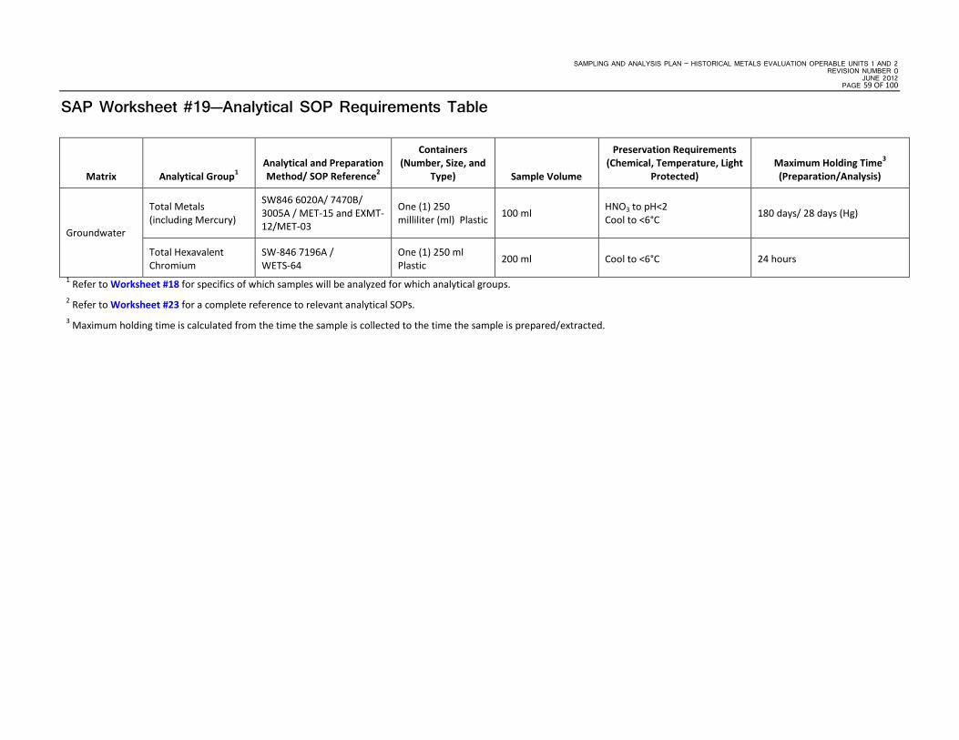
SAMPLING AND ANALYSIS PLAN – HISTORICAL METALS EVALUATION OPERABLE UNITS 1 AND 2 REVISION NUMBER 0
JUNE 2012 PAGE 59 OF 100
SAP Worksheet #19—Analytical SOP Requirements Table
Matrix Analytical Group1 Analytical and Preparation Method/ SOP Reference2
Containers (Number, Size, and
Type) Sample Volume
Preservation Requirements
(Chemical, Temperature, Light Protected)
Maximum Holding Time3 (Preparation/Analysis)
Groundwater
Total Metals (including Mercury)
SW846 6020A/ 7470B/ 3005A / MET-15 and EXMT-12/MET-03
One (1) 250 milliliter (ml) Plastic 100 ml HNO3 to pH<2
Cool to <6°C 180 days/ 28 days (Hg)
Total Hexavalent Chromium
SW-846 7196A / WETS-64
One (1) 250 ml Plastic 200 ml Cool to <6°C 24 hours
1 Refer to Worksheet #18 for specifics of which samples will be analyzed for which analytical groups. 2 Refer to Worksheet #23 for a complete reference to relevant analytical SOPs. 3 Maximum holding time is calculated from the time the sample is collected to the time the sample is prepared/extracted.

SAMPLING AND ANALYSIS PLAN – HISTORICAL METALS EVALUATION OPERABLE UNITS 1 AND 2 REVISION NUMBER 0 JUNE 2012 PAGE 60 OF 100
This page intentionally left blank.

SAMPLING AND ANALYSIS PLAN – HISTORICAL METALS EVALUATION OPERABLE UNITS 1 AND 2 REVISION NUMBER 0
JUNE 2012 PAGE 61 OF 100
SAP Worksheet #20—Field Quality Control Sample Summary Table
Matrix Analytical Group
No. of Sampling Locations
No. of Field Duplicates
No. of MS/MSDs
No. of Equip.
Blanks1
Total No. of Samples
to Lab
Groundwater TAL Metals 80 8 4/4 3 99
Hexavalent Chromium 6 1 1/1 3 12 1The number of equipment blanks is based on a fundamental assumption of the number of sampling days each site will require.

SAMPLING AND ANALYSIS PLAN – HISTORICAL METALS EVALUATION OPERABLE UNITS 1 AND 2 REVISION NUMBER 0 JUNE 2012 PAGE 62 OF 100
This page intentionally left blank.

SAMPLING AND ANALYSIS PLAN – HISTORICAL METALS EVALUATION OPERABLE UNITS 1 AND 2 REVISION NUMBER 0
JUNE 2012 PAGE 63 OF 100
SAP Worksheet #21—Project Sampling SOP References Table
Reference Number Title, Revision Number, and/or Date Originating Organization Equipment Type Modified for
Project Work? Comments
SOP-001 Completing Log Books, rev. 5/2011
CH2M HILL
Log book indelible pen
No
SOP-002
Field Measurement of pH, Specific Conductance, Turbidity, Dissolved Oxygen, ORP, and Temperature Using a multi parameter water quality meter with Flow through Cell, rev. 10/2011
Water quality meter with flow-though cell
SOP-003 Low-Flow Groundwater Sampling from Monitoring Wells, rev. 10/2011
Peristaltic pump or submersible pump, plastic tubing
SOP-004 Decontamination of Personnel and Equipment, rev. 05/2011 Reusable sampling equipment
SOP-005 Disposal of Waste Solids and Fluids, rev. 05/2011 55-gallon drum with on-Base staging
SOP-006 Equipment Blank and Field Blank Preparation, rev. 05/2011
Lab-provided blank liquid and sample bottles
SOP-007 Packaging and Shipping Procedures for Low-Concentration Samples, rev. 05/2010 Lab-supplied coolers
SOP-008 Chain-of-Custody, rev. 05/2011 Chain-of-Custody Form
SOP-009 Photoionization Detector (PID), rev. 05/2011 PID
SOP-010 Water-Level Measurements, rev. 05/2011 Electronic water-level meter

SAMPLING AND ANALYSIS PLAN – HISTORICAL METALS EVALUATION OPERABLE UNITS 1 AND 2 REVISION NUMBER 0 JUNE 2012 PAGE 64 OF 100
This page intentionally left blank.

SAMPLING AND ANALYSIS PLAN – HISTORICAL METALS EVALUATION OPERABLE UNITS 1 AND 2 REVISION NUMBER 0
JUNE 2012 PAGE 65 OF 100
SAP Worksheet #22—Field Equipment Calibration, Maintenance, Testing, and Inspection Table
Field Equipment Activity1 Frequency Acceptance Criteria CA Responsible Person SOP Reference2 Comments
Peristaltic Pump/ Submersible Pump/ Bladder pump
Maintenance As Needed, Regularly
Specific per model/instruction manual
Rental and/or manufacturer support for pump malfunctions
FTL SOP-003
Multi-RAE/ Mini-RAE PID Calibrate sensor Daily, As Needed Parameter specific per model/ instruction Manual
Manufacturer technical support for calibration errors
FTL SOP-009
Water quality meter Calibrate probes Daily, As Needed Parameter specific per model/instruction manual
Manufacturer technical support for calibration errors
FTL SOP-002
1 Activities may include calibration, testing, and maintenance. 2 See Worksheet #21.

SAMPLING AND ANALYSIS PLAN – HISTORICAL METALS EVALUATION OPERABLE UNITS 1 AND 2 REVISION NUMBER 0 JUNE 2012 PAGE 66 OF 100
This page intentionally left blank.

SAMPLING AND ANALYSIS PLAN – HISTORICAL METALS EVALUATION OPERABLE UNITS 1 AND 2 REVISION NUMBER 0
JUNE 2012 PAGE 67 OF 100
SAP Worksheet #23—Analytical SOP References Table
Lab SOP Number Title, Revision Date and/or Number
Last Reviewed
Definitive or Screening
Data Matrix and
Analytical Group Instrument
Organization Performing
Analysis
Variance to QSM
Modified for Project
Work (Y/N)
LOGINS-03
Receiving Samples (Rev. 10, Effective 1/23/2010) 4/20/2011 NA NA NA ENCO - Orlando N N
EXMT-12 Acid Digestion of Aqueous Samples for Analysis by Inductively Coupled Plasma (ICP) and ICP- Mass Spectrometer (MS) (Rev. 5, 02/17/2012)
2/16/2012 NA Aqueous/ Metals Prep
NA ENCO - Orlando N N
MET-15 Metals Analysis using ICP-MS (Rev. 5, 02/14/11) NA Definitive Aqueous/Metals ICP/MS ENCO - Orlando Y - ENCO does not perform Methods
of Standard Addition
(MSA)
N
MET-03 Mercury in Waters by Digestion/Cold Vapor Atomic Absorption (CVAA) (Rev. 5, Effective 02/20/2012)
2/16/2012 Definitive Aqueous/Mercury CVAA ENCO-Orlando Y - ENCO does not perform
MSA
N
WETS-64 Hexavalent Chromium (Rev. 8, Effective 01/23/2010)
04/21/2011 Definitive Aqueous Hexavalent Chromium
Ultraviolet (UV) Visual
Spectroscopy (VIS)
ENCO - Orlando Y - ENCO does not perform
MSA
N
ADMIN-14 Waste Disposal and Characterization (Rev. 5, 12/1/2009)
9/16/2012 NA NA NA ENCO - Orlando N N

SAMPLING AND ANALYSIS PLAN – HISTORICAL METALS EVALUATION OPERABLE UNITS 1 AND 2 REVISION NUMBER 0 JUNE 2012 PAGE 68 OF 100
This page intentionally left blank.

SAMPLING AND ANALYSIS PLAN – HISTORICAL METALS EVALUATION OPERABLE UNITS 1 AND 2 REVISION NUMBER 0
JUNE 2012 PAGE 69 OF 100
SAP Worksheet #24—Analytical Instrument Calibration Table
Instrument Calibration Procedure Frequency of Calibration Acceptance Criteria CA Person Responsible for CA SOP Reference
ICP-MS (SW846 6020A)
Tuning Prior to initial calibration (ICAL).
Mass calibration ≤ 0.1 atomic mass unit (amu) from the true value; Resolution < 0.9 amu full width at 10% peak height; For stability, relative standard deviation (RSD) ≤ 5% for at least four replicate analyses.
Retune instrument then reanalyze tuning solutions.
Analyst MET-15
ICAL for all analytes (minimum 2 point calibration)
Daily ICAL prior to sample analysis. More than one calibration standard is used, percent recovery (%R) ≥ 0.995. Correct problem, then repeat ICAL.
Second source calibration verification
Once after each ICAL, prior to beginning a sample run.
Value of second source for all analytes within ± 10% of true value.
Verify second source standard. Rerun second source verification. If that fails, correct problem and repeat ICAL.
Continuing calibration verification (CCV)
After every 10 field samples and at the end of the analysis sequence. All analytes within ± 10% of true value.
Correct problem, rerun calibration verification. If that fails, then repeat ICAL. Reanalyze all samples since the last successful calibration verification.
Calibration blank Before beginning a sample run, after every 10 samples, and at end of the analysis sequence.
No analytes detected > LOD. Correct problem. Re-prep and reanalyze calibration blank. All samples following the last acceptable calibration blank must be reanalyzed.
Interference check solutions (ICS-A and ICS-AB)
At the beginning of an analytical run and every 12 hours.
ICS-A: Absolute value of concentration for all non-spiked analytes < LOD (unless they are a verified trace impurity from one of the spiked analytes); ICS-AB: Within ± 20% of true value.
Terminate analysis, locate and correct problem, reanalyze ICS, reanalyze all samples.
UV-VIS (SW-846 7196A)
ICAL - minimum three standards and a calibration blank
Daily ICAL prior to sample analysis. %R ≥ 0.995 Correct problem and repeat ICAL. Flagging criteria are not appropriate.
Analyst WETS-64
Second Source Calibration Verification (ICV) Before beginning a sample run. Value of second source within ± 10% of true value.
Correct problem and verify second source standard. Rerun ICV, if that fails, correct problem and repeat calibration. Flagging criteria are not appropriate.
Continuing Calibration Verification (CCV)
After every 15 field samples and at the end of the analysis sequence. Value of CCV within of ± 10% the true value.
Correct problem then repeat CCV and reanalyze all samples since last successful calibration verification. If reanalysis cannot be preformed, data must be qualified and explained in the case narrative. Apply Q-flag to all results for the specific analyte(s) in all samples since the last acceptable calibration verification.
SAMPLING AND ANALYSIS PLAN – HISTORICAL METALS EVALUATION OPERABLE UNITS 1 AND 2 REVISION NUMBER 0 JUNE 2012 PAGE 70 OF 100
This page intentionally left blank.

SAMPLING AND ANALYSIS PLAN – HISTORICAL METALS EVALUATION OPERABLE UNITS 1 AND 2 REVISION NUMBER 0
JUNE 2012 PAGE 71 OF 100
SAP Worksheet #25—Analytical Instrument and Equipment Maintenance, Testing, and Inspection Table
Instrument/ Equipment Maintenance Activity
Testing Activity Inspection Activity Frequency
Acceptance Criteria
Corrective Action
Responsible Person
SOP Reference
ICP-MS (SW846 6020A)
Clean, inspect, change cones. Monitor ISTD counts for variation
Instrument performance and sensitivity.
As needed. Monitor ISTD counts for variation.
Re-calibrate.
Analyst
MET-15 Clean, inspect, change spray chamber ,injector, torch.
Monitor ISTD counts for variation
Instrument performance and sensitivity.
As needed. Monitor ISTD counts for variation.
Re-calibrate.
Replace pump windings. Monitor ISTD counts for variation
Instrument performance and sensitivity.
As needed. Monitor ISTD counts for variation.
Replace windings, re-calibrate and re-analyze.
CVAA (SW846 7196A)
Replace disposables, flush lines.
Sensitivity check
Instrument performance and sensitivity.
Daily or as needed.
CCV pass criteria. Recalibrate.
MET-16 Clean lens. Sensitivity check
Instrument performance and sensitivity.
Daily or as needed.
Method Blank pass criteria. Recalibrate.
Replace pump tubing. Flow Rate Check
Instrument performance and sensitivity.
As needed. Monitor flow rate for variation.
Replace windings, recalibrate and re-analyze.

SAMPLING AND ANALYSIS PLAN – HISTORICAL METALS EVALUATION OPERABLE UNITS 1 AND 2 REVISION NUMBER 0 JUNE 2012 PAGE 72 OF 100
This page intentionally left blank.

SAMPLING AND ANALYSIS PLAN – HISTORICAL METALS EVALUATION OPERABLE UNITS 1 AND 2 REVISION NUMBER 0
JUNE 2012 PAGE 73 OF 100
SAP Worksheet #26—Sample Handling System
SAMPLE COLLECTION, PACKAGING, AND SHIPMENT
Sample Collection (Personnel/Organization): Field Team/CH2M HILL
Sample Packaging (Personnel/Organization): FTL/CH2M HILL
Coordination of Shipment (Personnel/Organization): FTL/CH2M HILL
Type of Shipment/Carrier: Overnight Carrier/ FedEx
SAMPLE RECEIPT AND ANALYSIS
Sample Receipt (Personnel/Organization): Sample Custody Personnel / ENCO
Sample Custody and Storage (Personnel/Organization): Sample Custody Personnel / ENCO
Sample Preparation (Personnel/Organization): Sample Preparation Personnel / ENCO
Sample Determinative Analysis (Personnel/Organization): Analysts / ENCO
SAMPLE ARCHIVING
Field Sample Storage (No. of days from sample collection): 45 days
Sample Extract/Digestate Storage (No. of days from extraction/digestion): 45 days
Biological Sample Storage (No. of days from sample collection): NA
SAMPLE DISPOSAL
Personnel/Organization: Sample Disposal Personnel / ENCO
Number of Days from Analysis: 30 days from issuance of report

SAMPLING AND ANALYSIS PLAN – HISTORICAL METALS EVALUATION OPERABLE UNITS 1 AND 2 REVISION NUMBER 0 JUNE 2012 PAGE 74 OF 100
This page intentionally left blank.

SAMPLING AND ANALYSIS PLAN – HISTORICAL METALS EVALUATION OPERABLE UNITS 1 AND 2 REVISION NUMBER 0
JUNE 2012 PAGE 75 OF 100
SAP Worksheet #27—Sample Custody Requirements
Sample Labeling Procedures Sample labels will include, at a minimum, client name, site, sample ID, date/time collected, preservative, analysis group or method, and sampler’s initials. Each sample will be designated by an alphanumeric code that will identify the facility, site, station ID, matrix sampled, and/or date and depth sampled. QA/QC samples will have a unique sample designation. Nomenclature for samples and field QA/QC is specified in Worksheet #18. The field logbook will identify the sample ID with the location, depth, date/time collected, and the parameters requested.
Field Sample Custody Procedures (Sample Collection, Packaging, Shipment, and Delivery to Laboratory) Field samples will be collected by the field team members under the supervision of the FTL. As samples are collected, they will immediately be placed in the appropriate containers and labeled, as previously outlined. The labels will be filled out in the field by the field crew at the time of sample collection and checked before being placed into the cooler, at which time the sample will be logged in on the chain-of-custody form and field logbook. The integrity of the sample labels will be maintained through the practice of placing sample containers in watertight, resealable plastic bags.
Sample containers will be cushioned with packaging material and placed into coolers containing enough ice to keep the samples below 6 °C until they are received by the laboratory. The chain-of-custody form will also be placed into the cooler. Coolers will be shipped to the laboratory via FedEx, with the airbill number indicated on the chain-of-custody form (to relinquish custody). The FTL is responsible for the care and custody of samples until they are shipped or otherwise delivered to the laboratory custodian, as described in Section 4.3 of the Master Project Plans (CH2M HILL, 2008). Upon delivery, the laboratory will log in each cooler and report the status of the samples as discussed in the following sections.
Chain-of-custody Procedures Chain-of-custody forms will include, at a minimum, laboratory contact information, client contact information, sample information, and relinquished by/received by information. Sample information will include sample ID, date/time collected, number and type of containers, preservative information, analysis method, and comments. The chain-of-custody form will also have the sampler’s name and signature. The chain-of-custody will link location of the sample from the field logbook to the laboratory receipt of the sample. The laboratory will use the sample information to populate the laboratory information management system database for each sample.
Laboratory Sample Custody Procedures (Receipt of Samples, Archiving, Disposal) The laboratory receiving samples will comply with all sample custody requirements outlined in the laboratory SOPs referenced in Worksheet #23.
All samples from will be shipped to ENCO-Orlando.

SAMPLING AND ANALYSIS PLAN – HISTORICAL METALS EVALUATION OPERABLE UNITS 1 AND 2 REVISION NUMBER 0 JUNE 2012 PAGE 76 OF 100
SAP Worksheet #27—Sample Custody Requirements Table (continued)
Sample Integrity A sample tracking system will be followed to ensure sample authenticity and data defensibility. The Project Chemist will notify the laboratory of upcoming field sampling activities and the subsequent transfer of samples to the laboratory. The PDM will ensure that samples arrive to the lab in the appropriate timeframe and that the condition of samples upon receipt is satisfactory. If samples are not delivered to the lab in the acceptable timeframe or condition, the PM will be notified and the decision will be made whether to recollect samples.
The PDM is responsible for checking the chain-of-custody forms against the field logbook and field project instructions to verify the sample ID, times, analyses, and methods are correct on the forms. Any discrepancies will be resolved with the field team and relayed to the lab. These actions will be documented by both the lab and the PDM. The lab is responsible for providing the PDM with sample login sheets the day of sample receipt in order for the PDM to verify that the lab has accounted for all samples shipped and has correctly logged the samples into its software system.

SAMPLING AND ANALYSIS PLAN – HISTORICAL METALS EVALUATION OPERABLE UNITS 1 AND 2 REVISION NUMBER 0
JUNE 2012 PAGE 77 OF 100
SAP Worksheet #28-1—Laboratory QC Samples Table
Matrix: Groundwater
Analytical Group: TAL Metals (excluding Mercury)
Analytical Method/SOP Reference: SW846 6020A / MET-15
QC Sample: Frequency/Number Method/SOP QC Acceptance
Limits Corrective Action Person(s) Responsible for
Corrective Action Data Quality Indicator (DQI) Measurement Performance Criteria
Method Blank
One per preparatory batch.
No target analytes > 1/2 LOQ. Correct problem; then repeat. If the method blank still fails; redigest and analyze all affected samples.
Analyst
Bias/Contamination No target analytes > 1/2 LOQ.
LCS % Recovery = 80% - 120%
LCS is re-analyzed. If still fails, samples, along with QC, are re-prepped and re-analyzed. Client will be contacted for guidance about whether to re-prep samples. In the absence of client specific requirements, flag the data.
Precision and Accuracy/Bias % Recovery = 80% - 120%
MS Same as LCS. Perform a dilution test and/or post spike to evaluate matrix effects. Precision and Accuracy/Bias Same as LCS.
MSD Same as LCS and RPD ≤ 20%. Perform a dilution test and/or post spike to evaluate matrix effects. Precision and Accuracy/Bias Same as LCS and RPD ≤ 20%.
Dilution Test Recovery within ±10% of true value. Perform post spike. Precision and Accuracy/Bias Recovery within ±10% of true value.
Post Spike (PS) When dilution test fails or analyte concentration for all samples < 50x LOD.
Recovery within ±25% of true value.
If dilution test recovers outside of QC acceptance limits but post spike meets QC acceptance criteria , matrix effects are not confirmed, reprep and reanalyze sample.
Precision and Accuracy/Bias Recovery within ±25% of true value.
Internal Standard (IS) Spiked in every sample. IS intensity within 30-120% of intensity of IS in ICAL.
Re-analyze sample at 5X dilution with the addition of appropriate amounts of IS Precision and Accuracy IS intensity within 30-120% of
intensity of IS in ICAL.
Analytical Group: Mercury
Analytical Method/SOP Reference: SW846 7470B/ MET-03
QC Sample: Frequency/Number Method/SOP QC Acceptance
Limits Corrective Action Person(s) Responsible for Corrective
Action Data Quality Indicator (DQI Measurement Performance Criteria
Method Blank
One per preparatory batch.
No target analytes > 1/2 LOQ. Correct problem; then repeat. If the method blank still fails; redigest and analyze all affected samples.
Analyst
Bias/Contamination No target analytes > 1/2 LOQ.
LCS %R = 80% - 120%
LCS is re-analyzed. If still fails, samples, along with QC, are re-prepped and re-analyzed. Client will be contacted for guidance about whether to re-prep samples. In the absence of client specific requirements, flag the data.
Precision and Accuracy/Bias %R = 80% - 120%
MS In the absence of client specific requirements, flag the data. Precision and Accuracy/Bias
MSD %R = 80% - 120% and RPD ≤ 20%. In the absence of client specific requirements, flag the data. Precision and Accuracy/Bias %R = 80% - 120% and RPD ≤ 20%.

SAMPLING AND ANALYSIS PLAN – HISTORICAL METALS EVALUATION OPERABLE UNITS 1 AND 2 REVISION NUMBER 0 JUNE 2012 PAGE 78 OF 100
SAP Worksheet #28-2—Laboratory QC Samples Table
Matrix: Groundwater
Analytical Group: Hexavalent Chromium
Analytical Method/SOP Reference: SW846 7196A / WETS-64
QC Sample: Frequency/Number Method/SOP QC Acceptance
Limits CA Person(s) Responsible for CA DQI Measurement Performance Criteria
Reference Blank (Reagent Water) Before beginning standards or sample analysis NA NA
Analyst
NA NA
Method Blank One per preparatory batch.
No analytes detected > 1/2 reporting limit (RL) and > 1/10 the amount measured in any sample or 1/10 the regulatory limit (whichever is greater). Blank result must not otherwise affect sample results.
Correct problem, then see criteria in Box D-1 of Department of Defense (DoD) Quality Systems Manual (QSM) v. 4.1. If required, reprep and reanalyze method blank and all samples processed with the contaminated blank. If reanalysis cannot be performed, data must be qualified and explained in the case narrative. Apply B-flag to all results for the specific analytes(s) in all samples in the associated preparatory batch.
Accuracy/Bias, Contamination
No analytes detected > 1/2 RL and > 1/10 the amount measured in any sample or 1/10 the regulatory limit (whichever is greater). Blank result must not otherwise affect sample results.
LCS One per preparatory batch %R = 85% - 115% Correct problem, then reprep and reanalyze the LCS and all samples in the associated batch for the failed analyte in all samples in the associated preparatory batch, if sufficient sample material is available.
Accuracy/Bias %R = 85% - 115%
MS Once for every sample matrix analyzed. %R = 85% - 115%
If check indicates interference, dilute and reanalyze sample; persistent interference indicates the need to use alternative method or analytical conditions, or to use method of standard additions. Flagging criteria are not appropriate.
Accuracy/Bias %R = 85% - 115%
MSD One per preparatory batch per matrix.
%R = 85% - 115% and % RPD < 30%
Examine the project-specific DQOs. Contact the client as to additional measure to be taken. Flagging criteria are not appropriate. Accuracy/Bias %R = 85% - 115% and % RPD < 30%

SAMPLING AND ANALYSIS PLAN – HISTORICAL METALS EVALUATION OPERABLE UNITS 1 AND 2 REVISION NUMBER 0
JUNE 2012 PAGE 79 OF 100
SAP Worksheet #29—Project Documents and Records Table
Sample Collection Documents and Records
Onsite Analysis Documents and Records
Offsite Analysis Documents and Records
Data Assessment Documents and Records Other
• Field Notebooks
• Chain-of-Custody Records
• Airbills
• Custody Seals
• CA Forms
• Electronic Data Deliverables
• ID of QC Samples
• Meteorological Data from Field (Logging daily weather)
• Sampling locations and sampling plan
• Sampling notes
• No onsite analysis will take place
• Sample Receipt, Chain-of-Custody, and Tracking Records
• Standard Traceability Logs
• Equipment Calibration Logs
• Sample Prep Logs
• Run Logs
• Equipment Maintenance, Testing, and Inspection Logs
• CA Forms
• Reported Field Sample Results
• Reported Result for Standards, QC Checks, and QC Samples
• Instrument printouts (raw data) for Field Samples, Standards, QC Checks, and QC Samples
• Data Package Completeness Checklists
• Sample disposal records
• Extraction/Clean-up Records
• Raw Data (stored on disk)
• Fixed Laboratory Audit Checklists
• Data Validation Reports
• CA Forms
• Laboratory QA Plan
• Method DL Study Information
• NA
Notes: Sample collection documents and records will be scanned and saved on the network server. Field parameters will be loaded into the database using the Field Data Entry Tool. Offsite analysis documents and records will be archived after a period of 6 months. Hardcopy deliverables from the data validator, as well as other data assessment documents and records, will be archived. All archived documents will be archived with Iron Mountain, Inc., headquartered at 745 Atlantic Avenue, Boston, Massachusetts, 02111.

SAMPLING AND ANALYSIS PLAN – HISTORICAL METALS EVALUATION OPERABLE UNITS 1 AND 2 REVISION NUMBER 0 JUNE 2012 PAGE 80 OF 100
This page intentionally left blank.

SAMPLING AND ANALYSIS PLAN – HISTORICAL METALS EVALUATION OPERABLE UNITS 1 AND 2 REVISION NUMBER 0
JUNE 2012 PAGE 81 OF 100
SAP Worksheet #30—Analytical Services Table
Matrix Analytical Group Sample
Locations/ID Number
Analytical Method Data Package Turnaround Time Laboratory / Organization
Backup Laboratory / Organization
Groundwater
TAL Metals Refer to Worksheets #18 and #20
SW846 6020/7470A
28 calendar days
ENCO-Orlando 10775 Central Port Drive
Orlando, FL 32824 Ronnie Wambles (407) 826-5314
TBD
Hexavalent Chromium SW846 7196A

SAMPLING AND ANALYSIS PLAN – HISTORICAL METALS EVALUATION OPERABLE UNITS 1 AND 2 REVISION NUMBER 0 JUNE 2012 PAGE 82 OF 100
This page intentionally left blank.

SAMPLING AND ANALYSIS PLAN – HISTORICAL METALS EVALUATION OPERABLE UNITS 1 AND 2 REVISION NUMBER 0
JUNE 2012 PAGE 83 OF 100
SAP Worksheet #31—Planned Project Assessments Table
Assessment Type Frequency
Internal or
External
Organization Performing Assessment
Person(s) Responsible for Performing
Assessment
Person(s) Responsible for Responding to Assessment
Findings
Person(s) Responsible for Identifying and
Implementing CA
Person(s) Responsible for Monitoring Effectiveness
of CA
Field Performance Audit
One during sampling activities Internal CH2M HILL
Kristin Rogers
PM
CH2M HILL
FTL
CH2M HILL
Kristin Rogers
PM
CH2M HILL
Kristin Rogers
PM
CH2M HILL
Offsite Laboratory Technical Systems Audit
Laboratory must have current DoD Environmental Laboratory Accreditation Program (ELAP) evaluation letter which will identify the period of performance. The laboratory must be re-evaluated prior to expiration of the period of performance.
External Third-Party Accrediting Body
TBD, Third-Party Accrediting Body
Lori Mangram
QAO
ENCO-Orlando
Lori Mangram
QAO
ENCO-Orlando
Anita Dodson, Program Chemist, CH2M HILL
Safe Behavior Observation
One during sampling activities Internal CH2M HILL
Site Safety Coordinator
CH2M HILL
Field Team Member observed
CH2M HILL
Carl Woods
H&S Manager
CH2M HILL
Site Safety Coordinator
CH2M HILL

SAMPLING AND ANALYSIS PLAN – HISTORICAL METALS EVALUATION OPERABLE UNITS 1 AND 2 REVISION NUMBER 0 JUNE 2012 PAGE 84 OF 100
This page intentionally left blank.

SAMPLING AND ANALYSIS PLAN – HISTORICAL METALS EVALUATION OPERABLE UNITS 1 AND 2 REVISION NUMBER 0
JUNE 2012 PAGE 85 OF 100
SAP Worksheet #32—Assessment Findings and Corrective Action Responses
Assessment Type Nature of Deficiencies
Documentation Individual(s) Notified
of Findings Timeframe of Notification
Nature of CA Response Documentation
Individual(s) Receiving Response
Timeframe for Response
Field Performance Audit Checklist and Written Audit Report
FTL
CH2M HILL Within 1 day of audit
Verbal and Memorandum
FTL
CH2M HILL Within 1 day of receipt of CA Form
Laboratory Performance and Systems Audits Written Audit Report
Lori Mangram
QAO
ENCO-Orlando
Within 2 months of audit Memorandum DoD ELAP Auditor
Within 2 months of receipt of initial notification.
Safe Behavior Observation Safe Behavior Observation Form
Carl Woods
H&S Manager
CH2M HILL
Within 1 week of safe behavior observation.
Memorandum Field Team Member
CH2M HILL Immediately

SAMPLING AND ANALYSIS PLAN – HISTORICAL METALS EVALUATION OPERABLE UNITS 1 AND 2 REVISION NUMBER 0 JUNE 2012 PAGE 86 OF 100
This page intentionally left blank.
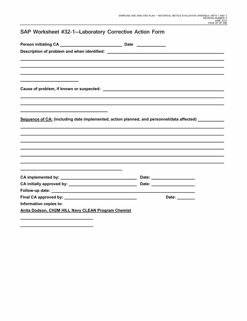
SAMPLING AND ANALYSIS PLAN – HISTORICAL METALS EVALUATION OPERABLE UNITS 1 AND 2 REVISION NUMBER 0
JUNE 2012 PAGE 87 OF 100
SAP Worksheet #32-1—Laboratory Corrective Action Form
Person initiating CA Date
Description of problem and when identified:
Cause of problem, if known or suspected:
Sequence of CA: (including date implemented, action planned, and personnel/data affected)
CA implemented by: Date: CA initially approved by: Date: Follow-up date: Final CA approved by: Date: Information copies to: Anita Dodson, CH2M HILL Navy CLEAN Program Chemist

SAMPLING AND ANALYSIS PLAN – HISTORICAL METALS EVALUATION OPERABLE UNITS 1 AND 2 REVISION NUMBER 0 JUNE 2012 PAGE 88 OF 100
This page intentionally left blank.

SAMPLING AND ANALYSIS PLAN – HISTORICAL METALS EVALUATION OPERABLE UNITS 1 AND 2 REVISION NUMBER 0
JUNE 2012 PAGE 89 OF 100
SAP Worksheet #32-2—Field Performance Audit Checklist
Project Responsibilities
Project No.: Date:
Project Location: Signature:
Team Members:
Yes No 1) Is the approved work plan being followed?
Comments
Yes No 2) Was a briefing held for project participants?
Comments
Yes No 3) Were additional instructions given to project participants?
Comments
Sample Collection
Yes No 1) Is there a written list of sampling locations and descriptions?
Comments
Yes No 2) Are samples collected as stated in the Master SOPs?
Comments
Yes No 3) Are samples collected in the type of containers specified in the work plan?
Comments
Yes No 4) Are samples preserved as specified in the work plan?
Comments
Yes No 5) Are the number, frequency, and type of samples collected as specified in the work plan?
Comments

SAMPLING AND ANALYSIS PLAN – HISTORICAL METALS EVALUATION OPERABLE UNITS 1 AND 2 REVISION NUMBER 0 JUNE 2012 PAGE 90 OF 100
SAP Worksheet #32-2—Field Performance Audit Checklist (continued)
Yes No 6) Are QA checks performed as specified in the work plan?
Comments
Yes No 7) Are photographs taken and documented?
Comments
Document Control
Yes No 1) Have any accountable documents been lost?
Comments
Yes No 2) Have any accountable documents been voided?
Comments
Yes No 3) Have any accountable documents been disposed of?
Comments
Yes No 4) Are the samples identified with sample tags?
Comments
Yes No 5) Are blank and duplicate samples properly identified?
Comments
Yes No 6) Are samples listed on a chain-of-custody record?
Comments
Yes No 7) Is chain-of-custody documented and maintained?
Comments

SAMPLING AND ANALYSIS PLAN – HISTORICAL METALS EVALUATION OPERABLE UNITS 1 AND 2 REVISION NUMBER 0
JUNE 2012 PAGE 91 OF 100
SAP Worksheet #33—QA Management Reports Table
Type of Report Frequency Projected Delivery Date(s) Person(s) Responsible for Report Preparation Report Recipient(s)
Field Audit Report One during sampling activities Submitted with Final Report
Kristin Rogers
PM
CH2M HILL
Included in project files.

SAMPLING AND ANALYSIS PLAN – HISTORICAL METALS EVALUATION OPERABLE UNITS 1 AND 2 REVISION NUMBER 0 JUNE 2012 PAGE 92 OF 100
This page intentionally left blank.
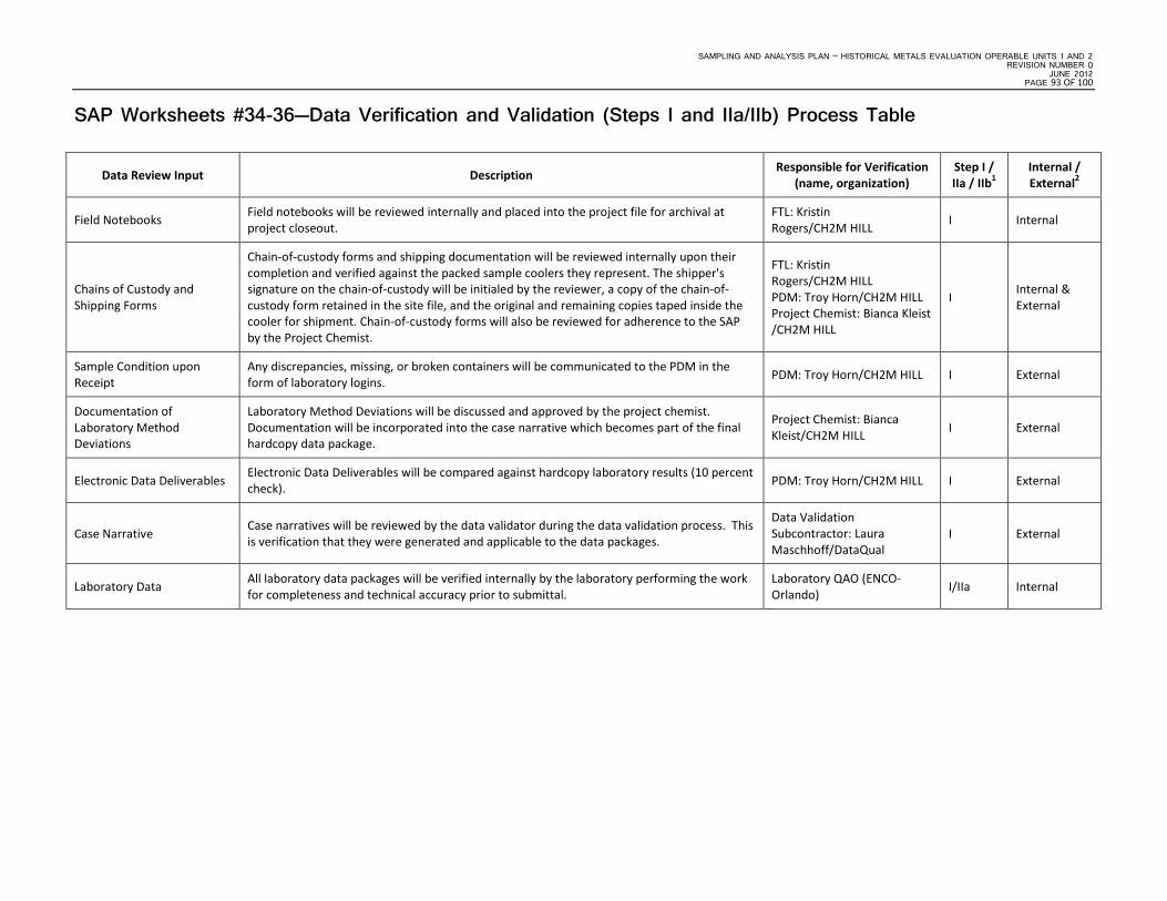
SAMPLING AND ANALYSIS PLAN – HISTORICAL METALS EVALUATION OPERABLE UNITS 1 AND 2 REVISION NUMBER 0
JUNE 2012 PAGE 93 OF 100
SAP Worksheets #34-36—Data Verification and Validation (Steps I and IIa/IIb) Process Table
Data Review Input Description Responsible for Verification (name, organization)
Step I / IIa / IIb1
Internal / External2
Field Notebooks Field notebooks will be reviewed internally and placed into the project file for archival at project closeout.
FTL: Kristin Rogers/CH2M HILL I Internal
Chains of Custody and Shipping Forms
Chain-of-custody forms and shipping documentation will be reviewed internally upon their completion and verified against the packed sample coolers they represent. The shipper's signature on the chain-of-custody will be initialed by the reviewer, a copy of the chain-of-custody form retained in the site file, and the original and remaining copies taped inside the cooler for shipment. Chain-of-custody forms will also be reviewed for adherence to the SAP by the Project Chemist.
FTL: Kristin Rogers/CH2M HILL PDM: Troy Horn/CH2M HILL Project Chemist: Bianca Kleist /CH2M HILL
I Internal & External
Sample Condition upon Receipt
Any discrepancies, missing, or broken containers will be communicated to the PDM in the form of laboratory logins. PDM: Troy Horn/CH2M HILL I External
Documentation of Laboratory Method Deviations
Laboratory Method Deviations will be discussed and approved by the project chemist. Documentation will be incorporated into the case narrative which becomes part of the final hardcopy data package.
Project Chemist: Bianca Kleist/CH2M HILL I External
Electronic Data Deliverables Electronic Data Deliverables will be compared against hardcopy laboratory results (10 percent check). PDM: Troy Horn/CH2M HILL I External
Case Narrative Case narratives will be reviewed by the data validator during the data validation process. This is verification that they were generated and applicable to the data packages.
Data Validation Subcontractor: Laura Maschhoff/DataQual
I External
Laboratory Data All laboratory data packages will be verified internally by the laboratory performing the work for completeness and technical accuracy prior to submittal.
Laboratory QAO (ENCO-Orlando) I/IIa Internal

SAMPLING AND ANALYSIS PLAN – HISTORICAL METALS EVALUATION OPERABLE UNITS 1 AND 2 REVISION NUMBER 0 JUNE 2012 PAGE 94 OF 100
SAP Worksheets #34-36—Data Verification and Validation (Steps I and IIa/IIb) Process Table (continued)
Data Review Input Description Responsible for
Verification (name, organization)
Step I / IIa / IIb1 Internal / External2
Laboratory Data The data will be verified for completeness by the PDM. PDM: Troy Horn/CH2M HILL I External
Audit Reports
Upon report completion, a copy of all audit reports will be placed in the site file. If CAs are required, a copy of the documented CA taken will be attached to the appropriate audit report in the QA site file. Periodically, and at the completion of site work, site file audit reports and CA forms will be reviewed internally to ensure that all appropriate CAs have been taken and that CA reports are attached. If CAs have not been taken, the site manager will be notified to ensure action is taken.
PM: Kristin Rogers/CH2M HILL Project Chemist: Bianca Kleist /CH2M HILL
I Internal
CA Reports CA reports will be reviewed by the Project Chemist or PM and placed into the project file for archival at project closeout.
PM: Kristin Rogers/CH2M HILL Project Chemist: Bianca Kleist / CH2M HILL
I External
Laboratory Methods Ensure the laboratory analyzed samples using the correct methods. Project Chemist: Bianca Kleist / CH2M HILL
IIa External
Target Compound List and TAL Ensure the laboratory reported all analytes from each analysis group. Project Chemist: Bianca Kleist / CH2M HILL
I/IIa External
RLs Ensure the laboratory met the PQLs. If PQLs were not met, the reason will be identified and documented.
Project Chemist: Bianca Kleist / CH2M HILL
IIb External
Field SOPs Ensure that all field SOPs were followed. FTL: Kristin Rogers/CH2M HILL IIa Internal

SAMPLING AND ANALYSIS PLAN – HISTORICAL METALS EVALUATION OPERABLE UNITS 1 AND 2 REVISION NUMBER 0
JUNE 2012 PAGE 95 OF 100
SAP Worksheets #34-36—Data Verification and Validation (Steps I and IIa/IIb) Process Table (continued)
Data Review Input Description Responsible for Verification (name, organization)
Step I / IIa / IIb1
Internal / External2
Laboratory SOPs Ensure that approved analytical laboratory SOPs were followed. Respective Laboratory QAOs IIa Internal
Raw Data 10 percent review of raw data to confirm laboratory calculations. Data Validation Subcontractor: Laura Maschhoff/DataQual IIa External
Onsite Screening All non-analytical field data will be reviewed against SAP requirements for completeness and accuracy based on the field calibration records. FTL: Kristin Rogers/CH2M HILL IIb Internal
Documentation of Method QC Results Establish that all required QC samples were run. Data Validation Subcontractor: Laura
Maschhoff/DataQual IIa External
Documentation of Field QC Sample Results Establish that all required QC samples were run. Project Chemist: Bianca Kleist
/CH2M HILL IIb Internal
DoD ELAP Evaluation Ensure that each laboratory is DoD ELAP Certified for the analyses they are to perform. Ensure evaluation timeframe does not expire.
Project Chemist: Bianca Kleist /CH2M HILL IIb External
Groundwater: TAL Metals and Hexavalent Chromium
Analytical methods and laboratory SOPs as presented in this SAP will be used to evaluate compliance against QA/QC criteria. Should adherence to QA/QC criteria yield deficiencies, data may be qualified. The data qualifiers used are those presented in National Functional Guidelines for Organic Data Review (EPA, October 1999). National Functional Guidelines will not be used for data validation; however, the specific qualifiers listed therein may be applied to data should non-conformances against the QA/QC criteria as presented in this SAP be identified.
Data Validation Subcontractor: Laura Maschhoff/DataQual IIa External
1 Verification (Step I) is a completeness check that is performed before the data review process continues in order to determine whether the required information (complete data package) is available for further review. Validation (Step IIa) is a review that the data generated is in compliance with analytical methods, procedures, and contracts. Validation (Step IIb) is a comparison of generated data against measurement performance criteria in the SAP (both sampling and analytical). 2 Internal or external is in relation to the data generator.

SAMPLING AND ANALYSIS PLAN – HISTORICAL METALS EVALUATION OPERABLE UNITS 1 AND 2 REVISION NUMBER 0 JUNE 2012 PAGE 96 OF 100
This page intentionally left blank.

SAMPLING AND ANALYSIS PLAN – HISTORICAL METALS EVALUATION OPERABLE UNITS 1 AND 2 REVISION NUMBER 0
JUNE 2012 PAGE 97 OF 100
SAP Worksheet #37—Usability Assessment
Summarize the usability assessment process and all procedures, including interim steps and any statistics, equations, and computer algorithms that will be used:
Non-detected site contaminants will be evaluated to ensure that project required LODs (Worksheet #15) were achieved. If LODs were achieved and the verification and validation steps yielded acceptable data, then the data are considered usable.
The third-party data validator is the only party that may apply qualifiers to the data. Minor QC exceedances will result in “estimated” data, represented by J, NJ, and UJ qualifiers. Major QC exceedances will result in “rejected” data, represented by R-qualifiers. The effect on availability and usability of rejected results will be evaluated.
For statistical comparisons, non-detect values will be represented by a concentration equal to one-half the sample LOD. For duplicate sample results, the most conservative value will be used for project decisions.
Analytical data will be checked to ensure the values and any qualifiers are appropriately transferred to the electronic database. These checks include comparison of hardcopy data and qualifiers to the electronic data deliverable. Once the data have been uploaded into the electronic database, another check will be performed to ensure all results were loaded accurately.
Field and laboratory precision will be compared as the RPD between the two results. If the Measurement Performance Criteria defined in Worksheet#12 are exceeded, the data will be J-qualified.
Deviations from this UFP-SAP will be reviewed to assess whether CA is warranted and to assess impacts to achievement of project objectives.
Describe the evaluative procedures used to assess overall measurement error associated with the project.
To assess whether a sufficient quantity of acceptable data are available for decision-making, the data will be reconciled with measurement performance criteria following validation and review of DQIs.
If significant biases are detected with laboratory QA/QC samples, they will be evaluated to assess their impact on decision-making. Low biases will be described in greater detail because they represent a possible inability to detect compounds that may be present at the site.
If significant deviations are noted between lab and field precision, the cause will be further evaluated to assess their impact on decision-making.
Describe the documentation that will be generated during the usability assessment and how usability assessment results will be presented so that they identify trends, relationships (correlations), and anomalies:
Data tables will be produced to reflect detected and non-detected site COCs and geochemical parameters. Data qualifiers will be reflected in the tables and discussed in the data quality evaluation.
Figures will be produced to reflect areas of investigation, including environmental sampling locations and results.
If needed, a technical memorandum will be produced that will identify any data usability limitations and make recommendations for CA.
Identify the personnel responsible for performing the usability assessment.
The CH2M HILL team, including the PM and Project Chemist, will review the data and compile a presentation for the MCB CamLej Partnering Team. The MCB CamLej Partnering Team as a whole will assess the usability of the data.

SAMPLING AND ANALYSIS PLAN – HISTORICAL METALS EVALUATION OPERABLE UNITS 1 AND 2 REVISION NUMBER 0 JUNE 2012 PAGE 98 OF 100
This page intentionally left blank.

SAMPLING AND ANALYSIS PLAN – HISTORICAL METALS EVALUATION OPERABLE UNITS 1 AND 2 REVISION NUMBER 0
JUNE 2012 PAGE 99 OF 100
References
Baker Environmental, Inc. (Baker). 1993. Final Record of Decision, Operable Unit No. 2, Sites 6, 9, and 82, Marine Corps Base CamLej, North Carolina. September.
Baker. 1994. Final Record of Decision, Operable Unit No. 1, Sites 21, 24, and IR78, Marine Corps Base Camp Lejeune, North Carolina. September.
Baker. 1995. Explanation of Significant Difference, Operable Unit No. 1. Marine Corps Base Camp Lejeune. North Carolina. October.
Baker. 2002a. Land Use Control Implementation Plans. Marine Corps Base Camp Lejeune, North Carolina. July.
Baker. 2002b. Base Background Groundwater Study, Marine Corps Base Camp Lejeune, North Carolina. August.
CH2M HILL. 2008. Master Project Plans, Marine Corps Base Camp Lejeune, North Carolina. June.
CH2M HILL. 2010. Final Five-Year Review, Marine Corps Base Camp Lejeune, Jacksonville, North Carolina. August.
CH2M HILL. 2011a. Waste Management Plan, Marine Corps Base Camp Lejeune, Jacksonville, North Carolina. February.
CH2M HILL. 2011b. Final Long-term Monitoring Report Fiscal Year 2010, Marine Corps Base Camp Lejeune, Jacksonville, North Carolina. June.
CH2M HILL. 2011c. Site Management Plan Fiscal Year 2012, Marine Corps Base Camp Lejeune, Jacksonville, North Carolina. October.
CH2M HILL. 2011d. Site 6 Supplemental Investigation – Interim Results Technical Memorandum, Marine Corps Base Camp Lejeune, Jacksonville, North Carolina. October.
CH2M HILL. 2011e. Draft Expanded Groundwater Background Study Report, Marine Corps Base Camp Lejeune, Jacksonville, North Carolina. December.
OHM. 1997. Contractor’s Closeout Report for Sites 6 and 82 Source Removal, Marine Corps Base Camp Lejeune, Jacksonville, North Carolina.
Rhea Engineers & Consultants, Inc (Rhea). 2010. Final Phase II Lot 203 ECP for Property Real Estate, DRMO Area, Marine Corps Base Camp Lejeune, North Carolina. March.
United States Environmental Protection Agency (EPA). 2002. Guidance for QAPPs, USEPA QA/G-5, Quality Assurance Management Section (QAMS). EPA QA/G-5. October.
EPA. 2005. Intergovernmental Data Quality Task Force Uniform Federal Policy for Quality Assurance Plans (UFP-QAPP). March.
EPA. 2006. Guidance on Systematic Planning Using the Data Quality Objectives Process. USEPA Office of Environmental Information, EPA/240/B-06/001. February.
United States Marine Corps (USMC). 1997. Notice of Non-Significant Changes: OU 1 (Sites 24 and 78) and OU 5 (Site 2). July.

SAMPLING AND ANALYSIS PLAN – HISTORICAL METALS EVALUATION OPERABLE UNITS 1 AND 2 REVISION NUMBER 0 JUNE 2012 PAGE 100 OF 100
This page intentionally left blank.

Figures

Site 78
Site 24
Site 82
Site 6
Site 21
Site 9
OU 1
OU 2
HO
LCO
MB
BO
ULEVA
RD
PIN
EY
GR
EE
N R
OA
D
HOLCOMB BOULEVARD
Figure 10-1Regional Location Map
Sampling and Analysis PlanHistorical Metals Evaluation Operable Units 1 and 2
MCB CamLejNorth Carolina
´0 3,000 6,0001,500
Feet
1 inch = 3,000 feet
\\NORTHEND\PROJ\USNAVFACENGCOM\CAMPLEJEUNE\MAPFILES\OU1_OU2\METALS_SAMPLING_WP\FIGURE_10_1_OU1_OU2_REGIONAL_LOC_MAP.MXD CELEFTHE 1/16/2012 10:05:01 AM
LegendHighwaysSite BoundariesOperable UnitsInstallation Boundary
OU1 and OU2
Atlantic Ocean
NewRiver
US H
WY
17ST ATE HWY 24
NewRiver

!<
!<
!<
!<!<!<!<
!<
!<
!<
!<
!<!<!<
!<
!<
!<
!<
!<
!<
!<
!<
!<!<
!<
!<
!<
!<
!<
!<
!<
!<!<!<
!<
!<
!<
!<!<
!<!<
!<!<
!<
!<
!<!<
!<
!<
!<
!<
!<
!<
!<!<
!<!<
!<!<
!<
!<
!<
!<!<
!<!<
!<!<
!<
!<
!<
!<!<
!<
!<
!<
!<
!<
!<
!<
!<
!<
!<
!<!<!<!<
!<!<!<!<!<
!<!<
!<
!<!<
!<!<
!<
!<
!< !<
!<
!<
!?
!?
!?
!?
!?
!<
!?
!?
!?
!?
!?
!<!<!<
!<
!<
IR78-MWVI01
IR78-GW17-4
IR78-GW86DW
IR78-GW84IW
IR78-GW85IWIR78-GW85
IR78-RW15
IR78-RW14
IR78-RW11
IR78-RW10
IR78-RW08
IR78-RW07
IR78-RW06
IR78-RW05
IR78-GW78IR78-GW77
IR78-GW76
IR78-GW72IR78-GW71
IR78-GW70
IR78-GW68
IR78-GW67
IR78-GW66
IR78-GW65
IR78-GW64
IR78-GW63
IR78-GW62
IR78-GW61
IR78-GW59
IR78-GW58
IR78-GW57
IR78-GW56
IR78-GW55
IR78-GW53
IR78-GW51
IR78-GW50
IR78-GW49
IR78-GW48
IR78-GW47 IR78-GW46
IR78-GW45
IR78-GW41
IR78-GW40
IR78-GW39
IR78-GW38
IR78-GW37
IR78-GW36 IR78-GW35
IR78-GW34
IR78-GW33
IR78-GW29
IR78-GW26
IR78-GW25
IR78-GW23
IR78-GW22
IR78-GW21
IR78-GW20
IR78-GW19
IR78-GW18
IR78-GW16
IR78-GW15
IR78-GW14
IR78-GW13
IR78-GW12
IR78-GW11
IR78-GW10
IR78-GW08IR78-GW07
IR78-GW06
IR78-GW05
IR78-GW03
IR78-GW02
IR78-RW09R
IR78-GW32-3IR78-GW32-2
IR78-GW31-3IR78-GW31-2
IR78-GW22-2
IR78-GW17-3IR78-GW17-2
IR78-GW17-1
IR78-GW04-1IR78-GW04-2IR78-GW04-3
IR78-GW09-1
IR78-GW09-2IR78-GW09-3
IR78-GW24-1IR78-GW24-2IR78-GW24-3
IR78-GW30-2IR78-GW30-3
IR78-GW75-1IR78-GW75-2
IR78-GW52R
IR78-RW12
IR78-GW01
IR78-GW42
IR78-GW43
IR78-GW44
IR78-GW54
IR78-GW60
IR78-GW69
IR78-GW73
IR78-GW74
IR78-RW09
IR78-GW45R
IR78-GW80IW
IR78-GW83IW
IR78-GW82IW
IR78-GW81IW
IR78-GW79IW
IR78-GW81DW
IR78-GW80DW
IR78-GW52
IR78-GW58R
IR78-GW51R
84
1231
575
906
916
914
905
904
907915
1854
1230
1011
1118
1402
1117
1116
1201
1012
1101
1108
1211
1301
12121316
1317
89
1502
751
1445
509
1220
508
62
1860
1401
1770
FC115
903
1501
1601
1202
1005
1500
66
1775
15
1200
65
1041
59
60
63
901
1829
S962
909
1880
1323
407
510
514
503
524
511
1522
898
507
1780
87
1470
1140
401
895
1340
14
500
1747
HP513
HP504
HP512
1771
1450
16
913
897
1042
908
1336
1464
1465
HP505HP508
HP507
HP510HP560
1841
HP514
HP509
1403
HP503
1828
1810
1827
1855
1817
HP88
564
1120
1235
1119
50
1006
1038
1232
1308
1404
1015
HP1017
HP405
S1854A
1239
519
HP415 1804
1808
HP576
1710
1826
1819
1023
1332
64
1461
1462
1851
1057
400
TP464
501
516
STP466
858
1613
1463
FC132
1612
1880A
FC130
977
FC131
1765
1611
433
1306
FC127
FC128
1312
S1854C
S1854B
531
532
1407
1895
1406
512
1408
518
1206
403
1707
896
1409
1106
529
1107
13091413
1203
1503
1405
1204
1410
1205
1310
1311
1237
1104
445
535
FC129
FC134
1515
1014
1460
1610
1003
TP448
HP550
1775F
1775E
1775B
1775A
826
1450B1450A
1315
1775D
1775C
1829A
1829B
1450C
39 1829C
TP457
1307
PT3
1400
1037
976A
1701
TP440
1750
1238
HP51
PT30
1742
1111
1052
425
S90
HP1016
PT4
1459
S15A
FC138
1688
HP89A
16A
HP500
1005A1005C
FC140FC141
STP467
FC139
PT3C
PT5
1070
1018
TP454
TP456
1856
518A
1010
1450G
SPT2
S561
1068
1767
1450F
1141
HP89
1450E
1742A
1450D
SPT1
SPT32
1112
S892
HP502
S955
HP515
HP511
CONT76
CONT195
CONT196
CONT200
CONT194
CONT191
S1806
1019
CONT113
927
PT71
TP468
1054
SPT67
S1772
S1447
TP428
853
S1773
STP435
S1853
507A
S1746
1896
407A
S1836
NEW7637
TP429
S1401B
STP443
911
TP465
1231D
1728
1341
SPT18
S739
1884
S1231C
919
CONT81
967
S580
1893
TP445
1776
TP453
1231A
1425
SFC116
S58D
16B
1044
S1837
1883
642A
1231B
STP442
63A
S1855A
1451
S1841C
S1311A
S770A
FC148
1225
PT3A
S58C
444A
PT3B
MFCUATM
SPT27
S1056
SPT31
S1071
S1841D
S1808AS1808C
LOUIS ROAD
MICHAEL ROAD
GUM STREET
WEST ROAD
N STR
EET
McHUGH BOULEVARD
BIRCH STREET
CENTER ROAD
CEDAR STREET
O STR
EET
PINEY GREEN ROADM
STR
EET
PARACHUTE TOWER ROAD
RailRoad
Road
DUNCAN S
TREET
FRANKLIN STREET
ELM STREET
CAR WASH ROAD
L STREET
DOGWOOD STREET
MO
LLY PITCHER
Cone Way
HOLCOMB BOULE
VARD
HICKORY STREET
ASH STREET
ISMT ROAD
BST LOOP ROAD
BIRCH STREET
ASH STREET
O STREET
BIRCH STREET
DUNCAN STREET
DOGWOOD STREET
BIRCH STREET
BIRCH STREET
Figure 10-2OU1 Map
Sampling and Analysis PlanMCB CamLej
North Carolina
LegendMonitoring Wells!< Surficial Aquifer !< Surficial Aquifer (Not in LTM program)!< Middle Castle Hayne Aquifer !< Middle Castle Hayne Aquifer (Not in LTM program)
Recovery Wells!? Surficial Aquifer- Recovery Well
Surface Water CenterlineOperable UnitsSite 78 Boundary
Land Use Control BoundariesAquifer Use Control BoundaryIntrusive Activities Control Boundary (Groundwater)
V:\USNAVFACENGCOM\CAMPLEJEUNE\MAPFILES\OU1_OU2\METALS_SAMPLING_WP\FIGURE_10_2_SITE_78_OU1_MAP_LOCATION_MAP.MXD CELEFTHE 1/17/2012 11:34:10 AM
´0 700 1,400350
Feet
1 inch = 700 feet

!<
!<
!?
!?
!? !?
!<!<!<!<
!<!<
!<
!<
!<
!<
!<!<!<
!<!<
!<
!< !<
!<
!<
!<
!<
!<
!<
!<
!<
!<!<
!<!<
!<
!<
!<!<
!<
!<
!<
!<
!<!<!<
!<
!<
!<
!<
!<
!<
!<
!A
!<
!<!<!<
!<!<
!<!<
!<!A
!A
!A
!A
!A
!?
!?!?!?!?
!?
!<
!<
!<
!<
!<
!<
!<
!<
!<
!<
!<
!<
!<
IR06-82MW02
IR06-DRW02
IR06-GW01DA
IR06-GW01DB
IR06-GW02IR06-GW02DW
IR06-GW03
IR06-GW05
IR06-GW06
IR06-GW07DWIR06-GW07S IR06-GW08
IR06-GW09IR06-GW10
IR06-GW11
IR06-GW13
IR06-GW15D
IR06-GW18
IR06-GW19
IR06-GW21IR06-GW23
IR06-GW25
IR06-GW26
IR06-GW27DA
IR06-GW27DW
IR06-GW30
IR06-GW33 IR06-GW34
IR06-GW35D
IR06-GW36D
IR06-GW37D
IR06-GW38D
IR06-GW40DWAIR06-GW41
IR06-GW42
IR06-GW43DWIR06-MW03
IR06-MW03D
IR06-MW31IW
IR06-MW53R
IR06-MW56
IR06-MW57
IR06-MW58IWIR06-MW61IW
IR06-MW62IW
IR06-MW63IW
IR06-SRW01
IR06-SRW02IR06-SRW03
IR06-SRW05IR06-SRW06
IR06-GW39D
IR06-GW32
IR06-GW07D
IR06-GW16IW
IR06-GW27D
IR06-GW28D
IR06-GW30DW
IR06-MW57DW
IR06-MW62DW
IR06-MW63DWIR06-MW59DW
IR06-MW54DW
IR06-MW31DW
IR06-SRW04
IR06-MW60IW
IR06-MW59IW
IR06-MW58
IR06-MW57IWIR06-MW56IW
IR06-MW55
IR06-MW54IW
IR06-MW54
IR06-MW28DW
IR06-GW47
IR06-GW46
IR06-GW44
IR06-GW40DW
IR06-GW31
IR06-GW28S
IR06-GW28DW
IR06-GW16
IR06-GW12
IR06-GW04
IR06-GW01DIR06-GW01
IR06-DRW04
IR06-DRW03
IR06-DRW01IR06-82MW03
PARACHUTE TOWER ROAD
OLD BEAR CREEK ROAD
SNEA
DS FER
RY
RO
AD BST LOOP ROAD
PIN
EY G
REE
N R
OA
D
NORTH WALLACE CREEK ROAD
INC
IDE
NTA
L LOO
P RO
AD
HO
L CO
MB
BO
UL E
V AR
D
SPT67
S871
STP467
TP453
800
TP457
601
TP448
1072
PT3
PT33
803
1069
TP440
810
SPT32
679
807
TP445
STP443
TP468
804
823
982
811
TP464
TP465
1002
TP460
1081
490
PT71STP466
795
984
626
CONT76 TP454
S983
CONT12
PT3BPT3A
STP464DSTP464G
STP464B
978
CONT113
PT3C
´0 600 1,200300
Feet
1 inch = 600 feet
Figure 10-3OU2 Map
Sampling and Analysis PlanHistorical Metals Evaluation Operable Units 1 and 2
MCB CamLejNorth Carolina
V:\USNAVFACENGCOM\CAMPLEJEUNE\MAPFILES\OU1_OU2\METALS_SAMPLING_WP\FIGURE_10_3_SITE_6_OU2_MAP_LOCATION_MAP.MXD CELEFTHE 2/15/2012 11:03:29 AM
Legend
Monitoring Wells
!< Surficial Aquifer
!< Surficial Aquifer - Not Sampled
!A Upper Castle Hayne Aquifer - Not Sampled
!< Middle Castle Hayne Aquifer
!< Middle Castle Hayne Aquifer - Not Sampled
Recovery Wells!? Surficial Aquifer Recovery Well
!? Upper Castle Hayne Aquifer Recovery Well
!? Middle Castle Hayne Aquifer Recovery Well
Surface Water Centerline
Lot 201 and 203
Operable Units
Site 6 Boundary
UXO-22 Boundary
Land Use Control BoundariesAquifer Use Control Boundary
Intrusive Activities Control Boundary (Groundwater)
Intrusive Activities Control Boundary (Soil)
Non-Industrial Use Control Boundary
W A L L A C E C R E E K
Lot 201
Lot 203
B E A R H E A DC R E E K

Attachment 1 Site Health and Safety Plan

H e a l t h an d S a f e t y P lan
Sampling and Analysis Plan Operable Unit 1 and 2 Metals
Sampling
Prepared for
Department of the Navy
Naval Facilities Engineering Command Mid-Atlantic
January 2012

II
Contents
1.0 INTRODUCTION ..................................................................................................................................................... 1-1
1.1 CH2M HILL POLICY AND COMMITMENT ................................................................................................................ 1-2 1.1.1 Safe Work Policy ............................................................................................................................................... 1-2 1.1.2 Health and Safety Commitment ......................................................................................................................... 1-2 1.1.3 Project-Specific Health, Safety, and the Environment Goals ............................................................................ 1-2
2.0 APPLICABILITY ..................................................................................................................................................... 2-1
3.0 GENERAL PROJECT INFORMATION ............................................................................................................... 3-1
3.1 PROJECT INFORMATION AND BACKGROUND ............................................................................................................ 3-1 3.2 SITE BACKGROUND AND SETTING ............................................................................................................................ 3-1
OU 1, Site 78 ................................................................................................................................................................... 3-1 OU 2, Sites 6 and 82 ........................................................................................................................................................ 3-1
3.3 DESCRIPTION OF TASKS ........................................................................................................................................... 3-2 3.3.1 HAZWOPER-Regulated Tasks ........................................................................................................................... 3-2 3.3.2 Non-HAZWOPER-Regulated Tasks ................................................................................................................... 3-2
4.0 PROJECT ORGANIZATION AND RESPONSIBILITIES .................................................................................. 4-1
4.1 CLIENT ..................................................................................................................................................................... 4-1 4.2 CH2M HILL ............................................................................................................................................................ 4-1
4.2.1 Project Manager ................................................................................................................................................ 4-1 4.2.2 CH2M HILL Responsible Health and Safety Manager ..................................................................................... 4-2 4.2.3 CH2M HILL Project Environmental Manager .................................................................................................. 4-2 4.2.4 CH2M HILL Safety Coordinator ....................................................................................................................... 4-2
4.3 EMPLOYEE RESPONSIBILITIES .................................................................................................................................. 4-4 4.3.1 Employee Authority ........................................................................................................................................... 4-5
4.4 CLIENT CONTRACTORS ............................................................................................................................................ 4-5
5.0 STANDARDS OF CONDUCT ................................................................................................................................. 5-1
5.1 STANDARDS OF CONDUCT VIOLATIONS ................................................................................................................... 5-1 5.2 DISCIPLINARY ACTIONS ........................................................................................................................................... 5-1 5.3 SUBCONTRACTOR SAFETY PERFORMANCE .............................................................................................................. 5-1
5.3.1 Observed Hazard Form ..................................................................................................................................... 5-2 5.3.2 Stop Work Order ................................................................................................................................................ 5-2
5.4 INCENTIVE PROGRAM .............................................................................................................................................. 5-2 5.5 REPORTING UNSAFE CONDITIONS/PRACTICES .......................................................................................................... 5-3
6.0 SAFETY PLANNING AND CHANGE MANAGEMENT .................................................................................... 6-1
6.1 DAILY SAFETY MEETINGS AND PRE-TASK SAFETY PLANS ....................................................................................... 6-1 6.2 CHANGE MANAGEMENT .......................................................................................................................................... 6-1 6.3 AGENCY INSPECTION GUIDANCE ............................................................................................................................. 6-1
7.0 PROJECT HAZARD ANALYSIS ........................................................................................................................... 7-3
7.1 ACTIVITY HAZARD ANALYSIS .................................................................................................................................. 7-3 7.2 SUBCONTRACTOR ACTIVITY HAZARD ANALYSIS ..................................................................................................... 7-3
8.0 GENERAL HAZARDS AND CONTROLS ............................................................................................................ 8-1
8.1 BLOODBORNE PATHOGENS ...................................................................................................................................... 8-1 8.2 CHEMICAL STORAGE ................................................................................................................................................ 8-1
8.2.1 Storage of Flammable/Combustible Liquids ..................................................................................................... 8-1 8.2.2 Indoor Storage of Flammable/Combustible Liquids ......................................................................................... 8-2

III
8.2.3 Outside Storage of Flammable/Combustible Liquids ........................................................................................ 8-2 8.2.4 Storage of Hazardous Waste ............................................................................................................................. 8-2 8.2.5 Storage of Chemical Injection Chemicals/Materials ......................................................................................... 8-2
8.3 DRIVING SAFETY...................................................................................................................................................... 8-3 8.4 ELECTRICAL SAFETY ................................................................................................................................................ 8-3 8.5 FIELD VEHICLES....................................................................................................................................................... 8-4 8.6 FIRE PREVENTION .................................................................................................................................................... 8-5
8.6.1 Fire Extinguishers and General Fire Prevention Practices .............................................................................. 8-5 8.6.2 Dispensing of Flammable/Combustible Liquids ................................................................................................ 8-5
8.7 GENERAL PRACTICES AND HOUSEKEEPING .............................................................................................................. 8-5 8.8 HAZARD COMMUNICATION ...................................................................................................................................... 8-7 8.9 KNIFE USE ............................................................................................................................................................... 8-7 8.10 LIGHTING ................................................................................................................................................................. 8-7 8.11 MANUAL LIFTING ..................................................................................................................................................... 8-8 8.12 PERSONAL HYGIENE ................................................................................................................................................ 8-8 8.13 SHIPPING AND TRANSPORTATION OF HAZARDOUS MATERIALS ................................................................................ 8-8 8.14 SUBSTANCE ABUSE .................................................................................................................................................. 8-9
9.0 PROJECT-SPECIFIC HAZARD CONTROLS ..................................................................................................... 9-1
9.1 BENZENE ................................................................................................................................................................. 9-1 9.2 DRUM AND PORTABLE TANK HANDLING ................................................................................................................. 9-1 9.3 GROUNDWATER SAMPLING/WATER LEVEL MEASUREMENTS .................................................................................. 9-2 9.4 HAND AND POWER TOOLS ....................................................................................................................................... 9-3 9.5 TRAFFIC CONTROL ................................................................................................................................................... 9-4 9.6 UTILITIES (OVERHEAD) ............................................................................................................................................ 9-5 9.7 VINYL CHLORIDE ..................................................................................................................................................... 9-6 9.8 WORKING AROUND MATERIAL HANDLING EQUIPMENT ........................................................................................... 9-6 9.9 WORKING ALONE .................................................................................................................................................... 9-7
10.0 PHYSICAL HAZARDS AND CONTROLS ......................................................................................................... 10-1
10.1 NOISE..................................................................................................................................................................... 10-1 10.2 ULTRAVIOLET RADIATION (SUN EXPOSURE) .......................................................................................................... 10-1 10.3 TEMPERATURE EXTREMES ..................................................................................................................................... 10-2
10.3.1 Heat ................................................................................................................................................................. 10-3 10.3.2 Cold ................................................................................................................................................................. 10-4
10.4 RADIOLOGICAL HAZARDS ...................................................................................................................................... 10-9
11.0 BIOLOGICAL HAZARDS AND CONTROLS .................................................................................................... 11-1
11.1 BEES AND OTHER STINGING INSECTS ..................................................................................................................... 11-1 11.2 FERAL DOGS .......................................................................................................................................................... 11-1 11.3 MOSQUITO BITES ................................................................................................................................................... 11-1 11.4 POISON IVY, POISON OAK, AND POISON SUMAC .................................................................................................... 11-2 11.5 SNAKES .................................................................................................................................................................. 11-4 11.6 SPIDERS - BROWN RECLUSE AND WIDOW .............................................................................................................. 11-5 11.7 TICKS ..................................................................................................................................................................... 11-6
12.0 CONTAMINANTS OF CONCERN ...................................................................................................................... 12-1
13.0 SITE MONITORING ............................................................................................................................................. 13-1
13.1 DIRECT READING MONITORING SPECIFICATIONS ................................................................................................... 13-1 13.2 CALIBRATION SPECIFICATIONS ............................................................................................................................... 13-2 13.3 INTEGRATED PERSONAL AIR SAMPLING ................................................................................................................. 13-2
14.0 PERSONAL PROTECTIVE EQUIPMENT ......................................................................................................... 14-1
14.1 REQUIRED PERSONAL PROTECTIVE EQUIPMENT .................................................................................................... 14-1 14.2 RESPIRATORY PROTECTION ................................................................................................................................... 14-3
15.0 WORKER TRAINING AND QUALIFICATION ................................................................................................ 15-1
15.1 CH2M HILL WORKER TRAINING .......................................................................................................................... 15-1

IV
15.1.1 Hazardous Waste Operations Training ........................................................................................................... 15-1 15.1.2 First Aid/Cardiopulmonary Resuscitation ....................................................................................................... 15-2 15.1.3 Safety Coordinator Training ........................................................................................................................... 15-2 15.1.4 Site-Specific Training ...................................................................................................................................... 15-2 15.1.5 Project-Specific Training Requirements .......................................................................................................... 15-2
16.0 MEDICAL SURVEILLANCE AND QUALIFICATION .................................................................................... 16-1
16.1 HAZARDOUS WASTE OPERATIONS AND EMERGENCY RESPONSE ........................................................................... 16-1 16.2 JOB OR SITE-SPECIFIC MEDICAL SURVEILLANCE ................................................................................................... 16-1 16.3 RESPIRATOR USER QUALIFICATION ........................................................................................................................ 16-1 16.4 HEARING CONSERVATION ...................................................................................................................................... 16-1
17.0 SITE-CONTROL PLAN ......................................................................................................................................... 17-1
17.1 SITE-CONTROL PROCEDURES ................................................................................................................................. 17-1 17.2 REMEDIATION WORK AREA ZONES ....................................................................................................................... 17-1
17.2.1 Support Zone ................................................................................................................................................... 17-1 17.2.2 Contamination Reduction Zone ....................................................................................................................... 17-1 17.2.3 Exclusion Zone ................................................................................................................................................ 17-2 17.2.4 Other Controlled Areas ................................................................................................................................... 17-2
18.0 DECONTAMINATION .......................................................................................................................................... 18-1
18.1 CONTAMINATION PREVENTION .............................................................................................................................. 18-1 18.2 PERSONNEL AND EQUIPMENT DECONTAMINATION ................................................................................................ 18-1 18.3 DECONTAMINATION DURING MEDICAL EMERGENCIES .......................................................................................... 18-2 18.4 WASTE COLLECTION AND DISPOSAL ...................................................................................................................... 18-2 18.5 DIAGRAM OF PERSONNEL-DECONTAMINATION LINE ............................................................................................. 18-2
19.0 EMERGENCY RESPONSE PLAN ....................................................................................................................... 19-1
19.1 PRE-EMERGENCY PLANNING ................................................................................................................................. 19-1 19.2 EMERGENCY EQUIPMENT AND SUPPLIES ................................................................................................................ 19-1 19.3 INCIDENT RESPONSE .............................................................................................................................................. 19-2 19.4 EMERGENCY MEDICAL TREATMENT ...................................................................................................................... 19-2 19.5 EVACUATION ......................................................................................................................................................... 19-2 19.6 EVACUATION SIGNALS ........................................................................................................................................... 19-3 19.7 INCLEMENT WEATHER ........................................................................................................................................... 19-3
20.0 SPILL CONTAINMENT PROCEDURES............................................................................................................ 20-1
21.0 INSPECTIONS ........................................................................................................................................................ 21-1
21.1 PROJECT ACTIVITY SELF-ASSESSMENT CHECKLISTS ............................................................................................. 21-1 21.2 SAFE BEHAVIOR OBSERVATIONS ........................................................................................................................... 21-1
22.0 INCIDENT NOTIFICATION, REPORTING, AND INVESTIGATION .......................................................... 22-1
22.1 GENERAL INFORMATION ........................................................................................................................................ 22-1 22.2 SECTION DEFINITIONS ............................................................................................................................................ 22-1 22.3 REPORTING REQUIREMENTS .................................................................................................................................. 22-2 22.4 HITS SYSTEM AND INCIDENT REPORT FORM ........................................................................................................ 22-2 22.5 INJURY MANAGEMENT/RETURN-TO-WORK (FOR US/PUERTO RICO BASED CH2M HILL STAFF ONLY) ............... 22-2
22.5.1 Background ..................................................................................................................................................... 22-2 22.5.2 The Injury Management/Return-to-Work Notification Process:...................................................................... 22-3
22.6 SERIOUS INCIDENT REPORTING REQUIREMENTS .................................................................................................... 22-3 22.6.1 Serious Incident Determination ....................................................................................................................... 22-3 22.6.2 Serious Incident Reporting .............................................................................................................................. 22-4
22.7 INCIDENT ROOT CAUSE ANALYSIS ......................................................................................................................... 22-6 22.7.1 Corrective Actions ........................................................................................................................................... 22-7
23.0 RECORDS AND REPORTS .................................................................................................................................. 23-1

V
ATTACHMENTS
Attachment 1 Employee Signoff Form – Health and Safety Plan Attachment 2 Chemical Inventory/Register Form Attachment 3 Chemical-Specific Training Form Attachment 4 Project Activity Self-Assessment Checklists/Forms/Permits Attachment 5 Key Target Zero Program Elements Attachment 6 Fact Sheets Attachment 7 Observed Hazard Form Attachment 8 Stop Work Order Form Attachment 9 Agency Inspection Target Zero Bulletin Attachment 10 Completed CH2M HILL AHAs Attachment 11 Material Safety Data Sheets

VI
Approval
This site-specific Health and Safety Plan (HSP) has been written for use by CH2M HILL only. CH2M HILL claims no responsibility for its use by others unless that use has been specified and defined in project or contract documents. The plan is written for the specific site conditions and identified scope(s) of work and must be amended if those conditions or scope(s) of work change.
By approving this HSP, the Responsible Health and Safety Manager (RHSM) certifies that the personal protective equipment has been selected based on the project-specific hazard assessment.
Original Plan RHSM Approval: Carl Woods Date: May 10, 2011
Field Operations Manager Approval: Date:
Revisions Revisions Made By:K. Rogers/RDU Date:January 17, 2012
Description of Revisions to Plan: Updated PM information to Kristin Rogers, removed all sites except Sites 6, 78, and 82. Removed all activities that are not applicable (utility locating, drilling, boating, working over water).
Updated plan to capture latest corporate initiatives.
Revisions Approved By: Carl Woods Date: 1/18/12

1-1
1.0 Introduction

1-2
1.1 CH2M HILL Policy and Commitment 1.1.1 Safe Work Policy It is the policy of CH2M HILL to perform work in the safest manner possible. Safety must never be compromised. To fulfill the requirements of this policy, an organized and effective safety program must be carried out at each location where work is performed.
CH2M HILL believes that all injuries are preventable, and we are dedicated to the goal of a safe work environment. To achieve this goal, every employee on the project must assume responsibility for safety.
Every employee is empowered to:
• Conduct their work in a safe manner;
• Stop work immediately to correct any unsafe condition that is encountered; and
• Take corrective actions so that work may proceed in a safe manner.
Safety, occupational health, and environmental protection will not be sacrificed for production. These elements are integrated into quality control, cost reduction, and job performance, and are crucial to our success.
1.1.2 Health and Safety Commitment CH2M HILL has embraced a philosophy for health and safety excellence. The primary driving force behind this commitment to health and safety is simple: employees are CH2M HILL’s most significant asset and CH2M HILL management values their safety, health, and welfare. Also, top management believes that all injuries are preventable. CH2M HILL’s safety culture empowers employees at all levels to accept ownership for safety and take whatever actions are necessary to eliminate injury. Our company is committed to world-class performance in health and safety and also understands that world-class performance in health and safety is a critical element in overall business success.
CH2M HILL is committed to the prevention of personal injuries, occupational illnesses, and damage to equipment and property in all of its operations; to the protection of the general public whenever it comes in contact with the Company’s work; and to the prevention of pollution and environmental degradation.
Company management, field supervisors, and employees plan safety into each work task in order to prevent occupational injuries and illnesses. The ultimate success of CH2M HILL’s safety program depends on the full cooperation and participation of each employee.
CH2M HILL management extends its full commitment to health and safety excellence.
1.1.3 Project-Specific Health, Safety, and the Environment Goals All management and employees are to strive to meet the project-specific Health, Safety, and the Environment (HSE) goals outlined below. The team will be successful only if everyone makes a concerted effort to accomplish these goals. The goals allow the project to stay focused on optimizing the health and safety of all project personnel and, therefore, making the project a great success.
The Project has established eleven specific goals and objectives:
• Create an injury-free environment;
• Have zero injuries or incidents;
• Provide management leadership for HSE by communicating performance expectations, reviewing and tracking performance, and leading by example;
1-3
• Ensure effective implementation of the HSP through education, delegation, and team work;
• Ensure 100 percent participation in HSE compliance;
• Continuously improve our safety performance;
• Maintain free and open lines of communication;
• Make a personal commitment to safety as a value;
• Focus safety improvements on high-risk groups;
• Continue strong employee involvement initiatives; and
• Achieve health and safety excellence.

2-1
2.0 Applicability This HSP applies to:
• All CH2M HILL staff, including subcontractors and tiered subcontractors of CH2M HILL working on the site; and
• All visitors to the construction site in the custody of CH2M HILL (including visitors from the Client, the Government, the public, and other staff of any CH2M HILL company).
This HSP does not apply to the third-party contractors, their workers, their subcontractors, their visitors, or any other persons not under the direct control or custody of CH2M HILL.
This HSP defines the procedures and requirements for the health and safety of CH2M HILL staff and visitors when they are physically on the work site. The work site includes the project area (as defined by the contract documents) and the project offices, trailers, and facilities thereon.
This HSP will be kept onsite during field activities and will be reviewed as necessary. The HSP will be amended or revised as project activities or conditions change or when supplemental information becomes available. The HSP adopts, by reference, the Enterprise-wide Core Standards and Standard Operating Procedures (SOPs), as appropriate. In addition, the HSP may adopt procedures from the project Work Plan and any governing regulations. If there is a contradiction between this HSP and any governing regulation, the more stringent and protective requirement shall apply.
All CH2M HILL staff and subcontractors must sign the employee sign-off form included in this document as Attachment 1 to acknowledge review of this document. Copies of the signature page will be maintained onsite by the Safety Coordinator (SC).

3-1
3.0 General Project Information 3.1 Project Information and Background PROJECT NO: 424568
CLIENT: Department of the Navy Atlantic Division Naval Facilities Engineering Command
PROJECT/SITE NAME: Long-Term Monitoring Program SITE ADDRESS: Marine Corps Base Camp Lejeune, North Carolina
CH2M HILL PROJECT MANAGER: Kristin Rogers
CH2M HILL OFFICE: RDU
DATE HEALTH AND SAFETY PLAN PREPARED/REVISED: January, 2012
DATE(S) OF SITE WORK: April 9, 2012 - April 27, 2012
3.2 Site Background and Setting In 2010, the Department of the Navy (Navy), and Marine Corps Base Camp Lejeune (MCB CamLej) completed a Five-Year Review to evaluate the current remedies at MCB CamLej and determine whether the remedies remain protective of human health and the environment as outlined in the Record of Decision (ROD) or Action Memorandum. The protectiveness of the remedies was evaluated through review of reports, site visits and inspections, and community involvement. In addition, the Five-Year Review Report identifies any issues that may be preventing a particular remedy from functioning as designed or as appropriate, and that could endanger the protection of human health and the environment. One of the recommendations outlined in the MCB CamLej 2010 Five-Year Review included reassessing metals as potential contaminants of concern (COCs) in groundwater at OU 1 (Site 78) and OU 2 (Sites 6 and 82). Metals were removed from the long-term monitoring program at the two OUs; however, cleanup levels have changed and become more conservative. Historical metals data were reviewed and indicated screening criteria exceedances at OU 1 for arsenic, chromium, manganese, and vanadium and at OU 2 for chromium, manganese, and vanadium.
OU 1, Site 78 OU 1 (HPIA) is located approximately one mile east of the New River and two miles south of State Route 24. Site 78 is bordered by Holcomb Boulevard to the west, Sneads Ferry Road to the north, Louis Street to the east, and the Main Service Road to the south. Site 78 covers approximately 590 acres comprised of maintenance shops, warehouses, painting shops, printing shops, auto body shops, and other small industrial facilities. The site is relatively flat and the majority of the site area is paved (e.g., roadways, parking lots, loading dock areas, and storage lots); however, there are many small lawn areas associated with individual buildings within the site and along lengthy stretches of roadways. Recreational ball fields and a parade ground are located in the southwest corner of the site. The HPIA, constructed in the late 1930s, was the first developed area at MCB Camp Lejeune. Due to the industrial nature of the Site, spills and leaks have occurred over the operational period of the site.
OU 2, Sites 6 and 82 OU 2 is located approximately two miles east of the New River and two miles south of State Route 24. OU 2 is a predominantly flat area with sharp a drop-off in elevation near the banks of Wallace Creek, at the northern end of Site 82 and near Bear Head Creek, in the wooded area south of Lot 201. Site 6 is bounded by Site 82 to the north, by Piney Green Road to the east, by Site 9 to the south, and by Holcomb Boulevard to the west. Site 82 is bordered by Wallace Creek to the north, by Piney Green Road to the east, by Holcomb Boulevard to the west, and by Site 6 to the south.

3-2
Site 6 covers an area of approximately 177 acres that incorporates Storage Lots 201 and 203, a wooded area between the storage lots, and a ravine. Historically, Site 6 was used for disposal and storage of wastes and supplies, including pesticides, transformers containing polychlorinated biphenyls (PCBs), solvents, electrolytes, and waste oils. Currently, Lot 201 is used to store military equipment, vehicles, hydraulic oils, and other “non-hazardous” supplies. Lot 203 is no longer an active storage area.
Site 82, the Piney Green Road Volatile Organic Compound (VOC) site, encompasses approximately 30 acres and is predominantly covered by woodlands. This site was identified as a result of the 1986 site assessment at Site 6 and from the 1992 Site Inspection. The site is randomly littered with debris including spent ammunition casings, and empty or rusted drums. Some of the drums were marked as “lubrication oil” and “anti-freeze”.
See Site Map for work area.
3.3 Description of Tasks All CH2M HILL and Subcontractor employees engaging in hazardous waste operations (HAZWOPER) or emergency response shall receive appropriate training as required by 29 CFR 1910.120 and 29 CFR 1926.65 (or if required by Subcontract). Personnel who have not met these training requirements shall not be allowed to engage in hazardous waste operations or emergency response activities. See the following tasks that fall under HAZWOPER requirements. 3.3.1 HAZWOPER-Regulated Tasks
• Groundwater sampling
3.3.2 Non-HAZWOPER-Regulated Tasks Under specific circumstances, the training and medical monitoring requirements of federal or state Hazwoper regulations are not applicable. The following tasks do not involve exposure to safety or health hazards associated with the hazardous waste operations. Hazwoper training or medical requirements do not apply for the tasks listed below.
TASKS CONTROLS • Non-Intrusive Surveying • Brief on hazards, limits of
access, and emergency procedures.
• Post areas of contamination as appropriate.
• Perform air sampling/monitoring as specified in this HSP.

3-3
Site Map

4-1
4.0 Project Organization and Responsibilities 4.1 Client Navy Technical Representative (NTR): Mr. Dave Cleland. NAVFAC Mid-Atlantic, Code: OPCEV NC/Caribbean IPT,EV Business Line 6506 Hampton Blvd Norfolk, VA 23508 Base Environmental Management Division (EMD): Ms. Charity Rychak EMD/EQB Building 12, Post Lane (Room 243) Camp Lejeune, NC 28542 Phone: 910-451-9386
4.2 CH2M HILL 4.2.1 Project Manager PM Name: Kristin Rogers CH2M HILL Office: RDU Telephone Number: (919) 760-1789 Cellular Number: (765) 409-4278
The project manager (PM) is responsible for providing adequate resources (budget and staff) for project-specific implementation of the HSE management process. The PM has overall management responsibility for the tasks listed below. The PM may explicitly delegate specific tasks to other staff, as described in sections that follow, but retains ultimate responsibility for completion of the following in accordance with this document:
• Incorporate standard terms and conditions, and contract-specific HSE roles and responsibilities in contract and subcontract agreements (including flow-down requirements to lower-tier subcontractors).
• Select safe and competent subcontractors by:
− Choosing potential subcontractors based on technical ability and HSE performance; − Implementing the subcontractor prequalification process; − Ensuring that acceptable certificates of insurance, including CH2M HILL as named
additional insured, are secured as a condition of subcontract award; and − Ensuring HSE submittals, subcontract agreements, and appropriate site-specific safety
procedures are in place and accepted prior field mobilization. • Ensure copies of training and medical monitoring records, and site-specific safety procedures are
being maintained in the project file accessible to site personnel.
• Provide oversight of subcontractor HSE practices per the site-specific safety plans and procedures.
• Manage the site and interfacing with 3rd parties in a manner consistent with the contract and subcontract agreements and the applicable standard of reasonable care.
• Ensure that the overall, job-specific, HSE goals are fully and continuously implemented.

4-2
• Support and implement use of stop-work orders when subcontractor safety performance is not adequate.
4.2.2 CH2M HILL Responsible Health and Safety Manager RHSM Name: Carl Woods CH2M HILL Office: CIN Telephone Number: (513) 889-5771 Cellular Number: (513) 319-5771
The RHSM is responsible for the following:
• Review and evaluate subcontractor HSE performance using the pre-qualification process;
• Approve HSP and its revisions as well as Activity Hazard Analyses (AHA);
• Review and evaluate subcontractor site-specific safety procedures for adequacy prior to start of subcontractor’s field operations;
• Support the oversight (or SC’s direct oversight) of subcontractor and tiered subcontractor HSE practices;
• Permit upgrades and downgrades in respiratory protection after reviewing analytical data;
• Conduct audits as determined by project schedule and coordination with PM; and
• Participate in incident investigations, lessons learned, loss and near loss reporting.
4.2.3 CH2M HILL Project Environmental Manager EM Name: Hope Wilson CH2M HILL Office: ATL Telephone Number: (678) 530-4226 Cellular Number: (678) 530-5411
The Project EM is responsible for the following:
• Provide environmental program support in areas such as training, auditing, planning, permit tracking, and subcontractor oversight as needed or as specified in the project environmental plan;
• Review and evaluate qualifications for subcontractors with a history of environmental non-compliance and for waste transportation and disposal subcontractors;
• Evaluate any spills, releases, or environmental permit incidents for appropriate follow-up actions, notifications, and recordkeeping requirements; and
• Provide environmental compliance and environmental management expertise and advice to the project team as needed during the course of the project.
4.2.4 CH2M HILL Safety Coordinator SC Name: Kristin Rogers CH2M HILL Office: RDU Telephone Number: 919-760-1789 Cellular Number: 765-409-4278

4-3
The SC is responsible for verifying that the project is conducted in a safe manner including the following specific obligations:
• Verify this HSP is current and amended when project activities or conditions change;
• Verify CH2M HILL site personnel and subcontractor personnel read the HSP and sign the Employee Sign-Off Form, prior to commencing field activities;
• Verify CH2M HILL site personnel have completed any required specialty training (for example, fall protection, confined space entry, among others) and medical surveillance as identified in this HSP;
• Verify that project files available to site personnel include copies of executed subcontracts and subcontractor certificates of insurance (including CH2M HILL as named additional insured), bond, contractor’s license, training and medical monitoring records, and accepted site-specific safety procedures prior to start of subcontractor’s field operations;
• Act as the project “Hazard Communication Coordinator” and perform the responsibilities outlined in the HSP;
• Act as the project “Emergency Response Coordinator” and perform the responsibilities outlined in the HSP;
• Post the Occupational Safety and Health Administration (OSHA) job-site poster; the poster is required at sites where project field offices, trailers, or equipment-storage boxes are established;
• Hold and/or verify that safety meetings are conducted and documented in the project file initially and as needed throughout the course of the project (as tasks or hazards change);
• Verify that project health and safety forms and permits are being used as outlined this HSP;
• Perform oversight and assessments of subcontractor HSE practices per the site-specific safety plan and verify that project activity self-assessment checklists are being used as outlined this HSP;
• Coordinate with the RHSM regarding CH2M HILL and subcontractor operational performance, and 3rd party interfaces;
• Verify appropriate personal protective equipment (PPE) use, availability, and training;
• Ensure that the overall, job-specific, HSE goals are fully and continuously implemented;
• Conduct accident investigations including root cause analysis;
• Calibrate and conduct air monitoring in accordance with the HSP; maintain all air monitoring records in project file;
• Maintain HSE records and documentation;
• Facilitate OSHA or other government agency inspections including accompanying inspector and providing all necessary documentation and follow-up;
• Deliver field HSE training as needed based on project-specific hazards and activities;
• Contact the RHSM and PM in the event of an incident;
• When an apparent imminent danger exists, immediately remove all affected CH2M HILL employees and subcontractors, notify subcontractor safety representative, stop affected work until adequate corrective measures are implemented, and notify the PM and RHSM as appropriate; and
• Document all oral health and safety-related communications in project field logbook, daily reports, or other records.

4-4
4.3 CH2M HILL Subcontractors (Reference CH2M HILL SOP HSE-215, Contracts and Subcontracts)
Subcontractor: N/A Subcontractor Contact Name: Telephone:
Subcontractor: Subcontractor Contact Name: Telephone:
Subcontractors must comply with the following activities, and are responsible to:
• Comply with all local, state, and federal safety standards;
• Comply with project and owner safety requirements;
• Actively participate in the project safety program and either hold or attend and participate in all required safety meetings;
• Provide a qualified safety representative to interface with CH2M HILL;
• Maintain safety equipment and PPE for their employees;
• Maintain and replace safety protection systems damaged or removed by the subcontractor’s operations;
• Notify the SC of any accident, injury, or incident (including spills or releases) immediately and submit reports to CH2M HILL within 24 hours;
• Install contractually required general conditions for safety (for example, handrail, fencing, fall protection systems, floor opening covers);
• Conduct and document weekly safety inspections of project-specific tasks and associated work areas;
• Conduct site-specific and job-specific training for all subcontractor employees, including review of the CH2M HILL HSP, subcontractor HSPs, and subcontractor AHAs and sign appropriate sign-off forms; and
• Determine and implement necessary controls and corrective actions to correct unsafe conditions.
The subcontractors listed above may be required to submit their own site-specific HSP and other plans such as lead or asbestos abatement compliance plans. Subcontractors are responsible for the health and safety procedures specific to their work, and are required to submit their plans to CH2M HILL for review and acceptance before the start of field work.
Subcontractors are also required to prepare AHAs before beginning each activity posing hazards to their personnel. The AHA shall identify the principle steps of the activity, potential health and safety hazards for each step and recommended control measures for each identified hazard. In addition, a listing of the equipment to be used to perform the activity, inspection requirements, and training requirements for the safe operation of the equipment listed must be identified.

4-5
4.4 Employee Responsibilities All personnel are assigned responsibility for safe and healthy operations. This concept is the foundation for involving all employees in identifying hazards and providing solutions. For any operation, individuals have full authority to stop work and initiate immediate corrective action or control. In addition, each worker has a right and responsibility to report unsafe conditions or practices. This right represents a significant facet of worker empowerment and program ownership. Through shared values and a belief that all accidents are preventable, our employees accept personal responsibility for working safely.
Each employee is responsible for the following performance objectives:
• Perform work in a safe manner and produce quality results;
• Perform work in accordance with company policies, and report injuries, illnesses, and unsafe conditions;
• Complete work without injury, illness, or property damage;
• Report all incidents immediately to supervisor, and file proper forms with a human resources representative;
• Report all hazardous conditions and/or hazardous activities immediately to supervisor for corrective action; and
• Complete an HSE orientation prior to being authorized to enter the project work areas.
4.4.1 Employee Authority Each employee on the project has the obligation and authority to shut down any perceived unsafe work and during employee orientation, each employee will be informed of their authority to do so.
4.5 Client Contractors (Reference CH2M HILL SOP HSE-215, Contracts, Subcontracts and HSE Management Practices)
Contractor: N/A Contact Name: Telephone: Contractor Task(s):
This HSP does not cover contractors that are contracted directly to the client or the owner. CH2M HILL is not responsible for the health and safety or means and methods of the contractor’s work, and we must never assume such responsibility through our actions (such as advising on health and safety issues). In addition to these instructions, CH2M HILL team members should review contractor safety plans so that we remain aware of appropriate precautions that apply to us. Self-assessment checklists are to be used by the SC and CH2M HILL team members to review the contractor’s performance only as it pertains to evaluating CH2M HILL exposure and safety. The RHSM is the only person who is authorized to comment on or approve contractor safety procedures.
Health and safety-related communications with contractors should be conducted as follows:
• Request the contractor to brief CH2M HILL team members on the precautions related to the contractor’s work;
• When an apparent contractor non-compliance or unsafe condition or practice poses a risk to CH2M HILL team members:
− Notify the contractor safety representative;

4-6
− Request that the contractor determine and implement corrective actions; − If necessary, stop affected CH2M HILL work until contractor corrects the condition or
practice; and − Notify the client, PM, and RHSM as appropriate.
If apparent contractor non-compliance or unsafe conditions or practices are observed, inform the contractor safety representative (CH2M HILL’s obligation is limited strictly to informing the contractor of the observation; the contractor is solely responsible for determining and implementing necessary controls and corrective actions).
If an apparent imminent danger is observed, immediately warn the contractor employee(s) in danger and notify the contractor safety representative (CH2M HILL’s obligation is limited strictly to immediately warning the affected individual(s) and informing the contractor of the observation; the contractor is solely responsible for determining and implementing necessary controls and corrective actions).
All verbal health and safety-related communications will be documented in project field logbook, daily reports, or other records.

5-1
5.0 Standards of Conduct All individuals associated with this project must work injury-free and drug-free and must comply with the following standards of conduct, the HSP, and the safety requirements of CH2M HILL. Commonly accepted standards of conduct help maintain good relationships between people. They promote responsibility and self-development. Misunderstandings, frictions, and disciplinary action can be avoided by refraining from thoughtless or wrongful acts.
5.1 Standards of Conduct Violations All individuals associated with this project are expected to behave in a professional manner. Violations of the standards of conduct would include, but not be limited to:
• Failure to perform work;
• Inefficient performance, incompetence, or neglect of work;
• Willful refusal to perform work as directed (insubordination);
• Negligence in observing safety regulations, poor housekeeping, or failure to report on-the-job injuries or unsafe conditions;
• Unexcused or excessive absence or tardiness;
• Unwillingness or inability to work in harmony with others;
• Discourtesy, irritation, friction, or other conduct that creates disharmony;
• Harassment or discrimination against another individual;
• Failure to be prepared for work by wearing the appropriate construction clothing or bringing the necessary tools; or
• Violation of any other commonly accepted reasonable rule of responsible personal conduct.
5.2 Disciplinary Actions The Environmental Services (ES) business group employees, employees working on ES business group projects, and subcontractor employees are subject to disciplinary action for not following HSE rules and requirements. Potential disciplinary action is equally applicable to all employees including management and supervision. Disciplinary action may include denial of access to the worksite, warnings, reprimands, and other actions up to and including termination depending on the specific circumstances.
5.3 Subcontractor Safety Performance CH2M HILL should continuously endeavor to observe subcontractors’ safety performance and adherence to their plans and AHAs. This endeavor should be reasonable, and include observing for hazards or unsafe practices that are both readily observable and occur in common work areas. CH2M HILL is not responsible for exhaustive observation for hazards and unsafe practices. CH2M HILL oversight does not relieve subcontractors of their responsibility for effective implementation and compliance with the established plan(s).

5-2
5.3.1 Observed Hazard Form When apparent non-compliance or unsafe conditions or practices are observed, notify the subcontractor’s supervisor or safety representative verbally, and document using the Observed Hazard Form, included as an attachment to this HSP, and require corrective action.
If necessary, stop subcontractor’s work using the Stop Work Order Form until corrective actions is implemented for observed serious hazards or conditions. Update the Observed Hazard Form to document corrective actions have been taken. The subcontractor is responsible for determining and implementing necessary controls and corrective actions.
5.3.2 Stop Work Order CH2M HILL has the authority, as specified in the contract, and the responsibility to stop work in the event any CH2M HILL employee observes unsafe conditions or failure of the subcontractor to adhere to its safe-work practices, or observes a condition or practice that may result in a release or violation of an environmental requirement. This authority and action does not in any way relieve the subcontractor of its responsibilities for the means and methods of the work or, therefore, of any corrective actions. Failure to comply with safe work practices can be the basis for restriction or removal of the subcontractor staff from the job site, termination of the subcontract, restriction from future work, or all three.
When an apparent imminent danger is observed, immediately stop work and alert all affected individuals. Remove all affected CH2M HILL employees and subcontractor staff from the danger, notify the subcontractor’s supervisor or safety representative, and do not allow work to resume until adequate corrective measures are implemented. Notify the PM, Contract Administrator (KA) and RHSM.
When repeated non-compliance or unsafe conditions are observed, notify the subcontractor’s supervisor or safety representative and stop affected work by completing and delivering the Stop Work Order Form (attached to this HSP) until adequate corrective measures are implemented. Consult the KA to determine what the contract dictates for actions to pursue in event of subcontractor non-compliance including work stoppage, back charges, progress payments, removal of subcontractor manager, monetary penalties, or termination of subcontractor for cause.
5.4 Incentive Program Each project is encouraged to implement a safety incentive program that rewards workers for exhibiting exemplary safety behaviors. Actions that qualify are those that go above and beyond what is expected. Actions that will be rewarded include spotting and correcting a hazard, bringing a hazard to the attention of your foreman, telling your foreman about an incident, coming up with a safer way to get the work done, or stopping a crew member from doing something unsafe. The program will operate throughout the project, covering all workers. The incentive program will be communicated to all employees during the project employee orientation and project safety meetings.

5-3
5.5 Reporting Unsafe Conditions/Practices Responsibility for effective health and safety management extends to all levels of the project and requires good communication between employees, supervisors, and management. Accident prevention requires a pro-active policy on near misses, close calls, unsafe conditions, and unsafe practices. All personnel must report any situation, practice, or condition which might jeopardize the safety of our projects. All unsafe conditions or unsafe practices will be corrected immediately. CH2M HILL has zero tolerance of unsafe conditions or unsafe practices.
No employee or supervisor will be disciplined for reporting unsafe conditions or practices. Individuals involved in reporting the unsafe conditions or practices will remain anonymous.
The following reporting procedures will be followed by all project employees:
• Upon detection of any unsafe condition or practice, the responsible employee will attempt to safely correct the condition;
• The unsafe condition or practice will be brought to the attention of the worker’s direct supervisor, unless the unsafe condition or practice involves the employee’s direct supervisor. If so, the SC needs to be notified at once by the responsible employee;
• Either the responsible employee or responsible employee’s direct supervisor is responsible for immediately reporting the unsafe condition or practice to the SC;
• The SC will act promptly to correct the unsafe condition or practice; and
• Details of the incident or situation will be recorded by the SC in the field logbook or use the Observed Hazard Form if subcontractor was involved.

6-1
6.0 Safety Planning and Change Management 6.1 Daily Safety Meetings and Pre-Task Safety Plans Daily safety meetings are to be held with all project personnel in attendance to review the hazards posed and required HSE procedures and AHAs that apply for each day’s project activities. The Pre-Task Safety Plans (PTSPs) serve the same purpose as these general assembly safety meetings, but the PTSPs are held between the crew supervisor and their work crews to focus on those hazards posed to individual work crews.
At the start of each day’s activities, the crew supervisor completes the PTSP, provided as an attachment to this HSP, with input from the work crew, during their daily safety meeting. The day’s tasks, personnel, tools and equipment that will be used to perform these tasks are listed, along with the hazards posed and required HSE procedures, as identified in the HSP and AHA. The use of PTSPs promotes worker participation in the hazard recognition and control process while reinforcing the task-specific hazard and required HSE procedures with the crew each day.
6.2 Change Management This HSP addresses all known activities and associated hazards. As work progresses, if significant changes are identified which could affect health and safety at the site, coordinate with the RHSM to determine whether a HSP update is necessary.
The following are examples of changes that may require a revision to the plan:
• Change in CH2M HILL staff;
• New subcontractor to perform work;
• New chemicals brought to site for use;
• Change in scope or addition of new tasks;
• Change in contaminants of concern (COCs) or change in concentrations of COCs; and
• New hazards or hazards not previously identified that are not addressed in this HSP.
6.3 Agency Inspection Guidance (Reference CH2M HILL SOP HSE-201, Agency Inspections and Communications)
Agency inspections (e.g., OSHA, EPA, other regulatory agencies) are on the rise. CH2M HILL implements safety and environmental programs in order to ensure safety to workers, the public, and the environment. This plan addresses things like labeling containers, completing the hazard communication training using the attachments to this HSP, listing training requirements and PPE requirements, and addressing project-specific hazards. Field personnel need to contact the RHSM to update this plan if hazards are encountered that are not addressed.
Following is some pertinent information regarding OSHA inspections in 2011:
• The number of OSHA inspectors increased by 130;
• A goal has been set to conduct 44,000 workplace inspections which is up from 36,000;
• The definition for “Repeat Violations” will encompass the past 5 years versus 3 years;
• OSHA directors can only reduce fines by a maximum of 30%;
• Some fines will be increased between $3,000 and $4,000 per violation;

6-2
• Proposed legislature - Serious fines raised from $7,000 to $12,000; and
• Proposed legislature - Willful fines from $70,000 to $250,000.
SOP HSE-201 addresses agency inspections in detail, and the attached Target Zero Bulletin on Agency Inspections provides a good summary of the inspection process and what to do if an agency such as OSHA or EPA shows up at the site. It is critical immediate notification or the RHSM if an inspector arrives (and EM if it is environmental-related); they can help facilitate and make additional notifications. Please either post the Target Zero Bulletin at your field trailer or keep it with your Health and Safety Plan/Environmental Plan; make it a topic at a safety meeting and keep it readily available in the event of an inspection.

7-3
7.0 Project Hazard Analysis A health and safety risk analysis (Table 1) has been performed for each task. In the order listed below, the RHSM considers the various methods for mitigating the hazards. Employees are trained on this hierarchy of controls during their hazardous waste training and reminded of them throughout the execution of projects:
• Elimination of the hazards (use remote sampling methodology to avoid going into a confined space);
• Substitution (reduce exposure to vapors by using of a geoprobe instead of test pitting);
• Engineering controls (ventilate a confined space to improve air quality);
• Warnings (establish exclusion zones to keep untrained people away from hazardous waste work);
• Administrative controls (implement a work-rest schedule to reduce chance of heat stress); or
• Use of PPE (use of respirators when action levels are exceeded).
The hazard controls and safe work practices are summarized in the following sections of this HSP:
• General hazards and controls;
• Project-specific hazards and controls;
• Physical hazards and controls;
• Biological hazards and controls; and
• Contaminants of concern.
7.1 Activity Hazard Analysis An AHA must be developed for each CH2M HILL job activity. The AHA shall define the work tasks required to perform each activity, along with potential HSE hazards and recommended control measures for each hazard. In addition, a listing of the equipment to be used to perform the activity, inspection requirements to be performed and training requirements for the safe operation of the equipment listed must be identified. Workers are briefed on the AHA before performing the work and their input is solicited prior, during, and after the performance of work to further identify the hazards posed and control measures required. The AHA shall identify the work tasks required to perform each activity, along with potential HSE hazards and recommended control measures for each hazard.
The following hazard controls and applicable CH2M HILL core standards and SOPs should be used as a basis for preparing AHAs.
AHAs prepared for CH2M HILL activities are included as an attachment to this HSP.
7.2 Subcontractor Activity Hazard Analysis CH2M HILL subcontractors are required to provide AHAs specific to their scope of work on the project for acceptance by CH2M HILL. Each subcontractor shall submit AHAs for their field activities, as defined in their scope of work, along with their project-specific safety plan and procedures. Additions or changes in field activities, equipment, tools, or material used to perform work or hazards not addressed in existing AHAs requires either a new AHA to be prepared or an existing AHA to be revised.

7-4
Table 1 – General Activity Hazard Analysis
Potential Hazards
Project Activities
Mobilization/ Demobilization, (Including Site Preparation
Manual Land Clearing) Groundwater Well
Monitoring/Sampling, IDW Handling & Management Adverse Weather X X X Biological X X X Buried Utilities Brush cutters X Chemical Hazard-Dermal/Inhalation X X Drilling Electrical Safety X Fire Prevention X X X Hand & Power Tools X X X Haul Truck Operations X Heat Stress and Cold Stress X X X Heavy Equipment X Housekeeping X X X Manual Lifting X X X Mechanical Guarding Hazards Material Handling Hazards X X Noise X X X Pinch/Struck by Pressure Washing/Equip Decon. X Pressurized Lines/Equipment X Slips/Trips/Falls X X X Suspended Loads Vehicle Traffic X X X Visible Lighting X X X

8-1
8.0 General Hazards and Controls This section provides safe work practices and control measures used to reduce or eliminate potential hazards. It is a summarized list of requirements. Always consult the appropriate CH2M HILL SOP to ensure all requirements are implemented.
8.1 Bloodborne Pathogens (Reference CH2M HILL SOP HSE-202, Bloodborne Pathogens)
Exposure to bloodborne pathogens may occur when rendering first aid or cardiopulmonary resuscitation (CPR), or when coming into contact with landfill waste or waste streams containing potentially infectious material (PIM).
Employees trained in first-aid/CPR or those exposed to PIM must complete CH2M HILL’s 1-hour bloodborne pathogens computer-based training module annually. When performing first-aid/CPR the following shall apply:
• Observe universal precautions to prevent contact with blood or other PIMs. Where differentiation between body fluid types is difficult or impossible, consider all body fluids to be potentially infectious materials;
• Always wash your hands and face with soap and running water after contacting PIMs. If washing facilities are unavailable, use an antiseptic cleanser with clean paper towels or moist towelettes; and
• If necessary, decontaminate all potentially contaminated equipment and surfaces with chlorine bleach as soon as possible. Use one part chlorine bleach (5.25 percent sodium hypochlorite solution) diluted with 10 parts water for decontaminating equipment or surfaces after initially removing blood or other PIMs. Remove contaminated PPE as soon as possible before leaving a work area.
CH2M HILL will provide exposed employees with a confidential medical examination should an exposure to PIM occur. This examination includes the following procedures:
• Documenting the exposure;
• Testing the exposed employee's and the source individual's blood (with consent); and
• Administering post-exposure prophylaxis.
8.2 Chemical Storage The following are general guidelines for storing chemicals and other hazardous materials:
• Keep acids away from bases;
• Keep oxidizers (nitric acid, nitrates, peroxides, chlorates) and organics away from inorganic reducing agents (metals);
• Keep flammables and corrosives in appropriate storage cabinets;
• Do not store paper or other combustibles near flammables;
• Use secondary containment and lipped shelving that is secured; and
• Have a fire suppression system available.
8.2.1 Storage of Flammable/Combustible Liquids • Only approved containers and portable tanks shall be used for storage and handling of flammable
and combustible liquids.

8-2
• Approved safety cans shall be used for the handling and use of flammable liquids in quantities of 5 gallons (22.7 liters) or less. Do not use plastic gas cans.
• For quantities of 1 gallon (4.5 liters) or less, the original container may be used for storage and use of flammable liquids.
• Flammable or combustible liquids shall not be stored in areas used for stairways or normally used for the passage of people.
8.2.2 Indoor Storage of Flammable/Combustible Liquids • No more than 25 gallons (113.7 liters) of flammable or combustible liquids shall be stored in a room
outside of an approved storage cabinet.
• Quantities of flammable and combustible liquids in excess of 25 gallons (113.7 liters) shall be stored in an acceptable or approved cabinet.
• Cabinets shall be conspicuously lettered: "FLAMMABLE: KEEP FIRE AWAY."
• Not more than 60 gallons (272.8 liters) of flammable or 120 gallons (545.5 liters) of combustible liquids shall be stored in any one storage cabinet. Not more than three such cabinets may be located in a single storage area.
8.2.3 Outside Storage of Flammable/Combustible Liquids • Storage of containers (not more than 60 gallons [272.8 liters] each) shall not exceed 1,100 gallons
(5000 liters) in any one area. No area shall be within 20 feet (6.1 meters) of any building.
• Storage areas shall be graded to divert spills away from buildings and surrounded by an earthen dike.
• Storage areas may not be located near a storm drain. Overflow and spills must be diverted away from storm drains or surface waters.
• Storage areas shall be free from weeds, debris, and other combustible materials.
• Outdoor portable tanks shall be provided with emergency vent devices and shall not be closer than 20 feet (6.1 meters) to any building.
• Signs indicating no smoking shall be posted around the storage area.
8.2.4 Storage of Hazardous Waste • All facilities storing ignitable and combustible liquids and hazardous wastes must be designed,
constructed, maintained, and operated to minimize the possibility of a fire, explosion, or any release of hazardous constituents.
• Flammable wastes should be stored more than 50 feet from the property line.
8.2.5 Storage of Chemical Injection Chemicals/Materials When chemical injection remediation technologies are being used at a site, the following storage guidelines must be followed:
• Some injection chemicals, such as strong oxidizers, may have stringent storage requirements per local or National Fire Codes. Verify that appropriate storage provisions are in place prior to starting work.
NOTE: Counties and cities may have requirements specific to storing these chemicals. Also, storage and use of certain chemicals such as potassium permanganate and hydrogen peroxide may be subject to the new Chemical Facility Anti-Terrorism Standards of the Department of Homeland Security – the applicability depends on the chemical, quantity/concentration, and type of facility.

8-3
Please contact the project Environmental Manager to determine whether chemicals are subject to these standards.
• Injection chemicals must be stored in a designated, secured area with spill prevention capabilities. Review MSDS or other information to determine potential incompatible materials. Incompatible materials shall not be stored together. Ensure all containers are labeled.
8.3 Driving Safety Follow the guidelines below when operating a vehicle:
• Refrain from using a cellular phone while driving. Pull off the road, put the vehicle in park and turn on flashers before talking on a cellular phone;
• Never operate a personal digital assistant (PDA), or other device with e-mail, internet, or text messaging function while driving a vehicle;
• Obey speed limits; be aware of blind spots or other hazards associated with low visibility. Practice defensive driving techniques, such as leaving plenty of room between your vehicle and the one ahead of you;
• Do no drive while drowsy. Drowsiness can occur at any time, but is most likely after 18 hours or more without sleep;
• Maintain focus on driving. Eating, drinking, smoking, adjusting controls can divert attention from the road. Take the time to park and perform these tasks when parked rather than while driving; and
• Ensure vehicle drivers are familiar with the safe operation of vehicles of the type and size to be operated. Large vehicles such as full size vans and pick-ups have different vision challenges and handling characteristics than smaller vehicles.
8.4 Electrical Safety (Reference CH2M HILL SOP HSE-206, Electrical Safety)
Below are the hazard controls and safe work practices to follow when using electrical tools, extension cords, and/or other electrical-powered equipment or when exposed to electrical hazards. Ensure the requirements of the referenced SOP are followed:
• Only qualified personnel are permitted to work on unprotected energized electrical systems;
• Only authorized personnel are permitted to enter high-voltage areas;
• CH2M HILL employees who might from time to time work in an environment influenced by the presence of electrical energy must complete Awareness Level Electrical Safety Training located on the CH2M HILL Virtual Office;
• Do not tamper with electrical wiring and equipment unless qualified to do so. All electrical wiring and equipment must be considered energized until lockout/tagout procedures are implemented;
• Inspect electrical equipment, power tools, and extension cords for damage prior to use. Do not use defective electrical equipment, remove from service;
• CH2M HILL has selected Ground Fault Circuit Interrupters (GFCIs) as the standard method for protecting employees from the hazards associated with electric shock;
− GFCIs shall be used on all 120-volt, single phase 15 and 20-amphere receptacle outlets which are not part of the permanent wiring of the building or structure.

8-4
• An assured equipment grounding conductor program may be required under the following scenarios:
− GFCIs can not be utilized; − Client requires such a program to be implemented; or − Business group decides to implement program in addition to GFCI protection.
• Extension cords must be equipped with third-wire grounding. Cords passing through work areas must be covered, elevated or protected from damage. Cords should not be routed through doorways unless protected from pinching. Cords should not be fastened with staples, hung from nails, or suspended with wire;
• Electrical power tools and equipment must be effectively grounded or double-insulated and Underwriters Laboratory (UL) approved;
• Operate and maintain electric power tools and equipment according to manufacturers' instructions;
• Maintain safe clearance distances between overhead power lines and any electrical conducting material unless the power lines have been de-energized and grounded, or where insulating barriers have been installed to prevent physical contact. Maintain at least 10 feet (3 meters) from overhead power lines for voltages of 50 kV or less, and 10 feet (3 meters) plus 0.4 inches (1.0 cm) for every 1 kV over 50 kV;
• Temporary lights shall not be suspended by their electric cord unless designed for suspension. Lights shall be protected from accidental contact or breakage; and
• Protect all electrical equipment, tools, switches, and outlets from environmental elements.
8.5 Field Vehicles • Field vehicles may be personal vehicles, rental vehicles, fleet vehicles, or project vehicles.
• Maintain a first aid kit, bloodborne pathogen kit, and fire extinguisher in the field vehicle at all times.
• Utilize a rotary beacon on vehicle if working adjacent to active roadway.
• Familiarize yourself with rental vehicle features prior to operating the vehicle:
− Vision Fields and Blind Spots − Vehicle Size − Mirror adjustments − Seat adjustments − Cruise control features, if offered − Pre-program radio stations and Global Positioning System (GPS), if equipped
• Always wear seatbelt while operating vehicle.
• Adjust headrest to proper position.
• Tie down loose items if utilizing a van or pick-up truck.
• Close car doors slowly and carefully. Fingers can get pinched in doors.
• Park vehicle in a location where it can be accessed easily in the event of an emergency. If not possible, carry a phone.
• Have a designated place for storing the field vehicle keys when not in use.

8-5
• Ensure back-up alarms are functioning, if equipped. Before backing a vehicle, take a walk around the vehicle to identify obstructions or hazards. Use a spotter when necessary to back into or out of an area.
• See the Vehicle Accident Guidance attached to this HSP, if a vehicle incident is experienced in a rental or fleet vehicle.
8.6 Fire Prevention (Reference CH2M HILL SOP HSE-403, Hazardous Material Handling)
Follow the fire prevention and control procedures listed below.
8.6.1 Fire Extinguishers and General Fire Prevention Practices • Fire extinguishers shall be provided so that the travel distance from any work area to the nearest
extinguisher is less than 100 feet (30.5 meters). When 5 gallons (19 liters) or more of a flammable or combustible liquid is being used, an extinguisher must be within 50 feet (15.2 meters). Extinguishers must:
− be maintained in a fully charged and operable condition; − be visually inspected each month; and − undergo a maintenance check each year.
• The area in front of extinguishers must be kept clear.
• Post “Exit” signs over exiting doors, and post “Fire Extinguisher” signs over extinguisher locations.
• Combustible materials stored outside should be at least 10 feet (3 meters) from any building.
• Solvent waste and oily rags must be kept in a fire resistant, covered container until removed from the site.
• Keep areas neat. Housekeeping is important.
8.6.2 Dispensing of Flammable/Combustible Liquids • Areas in which flammable or combustible liquids are dispensed in quantities greater than 5 gallons
(22.7 liters) (shall be separated from other operations by at least 25 feet (7.6 meters).
• Drainage away from storm drains or surface waters or other means of containment shall be provided to control spills.
• Adequate natural or mechanical ventilation shall be provided to maintain the concentration of flammable vapor at or below 10 percent of the lower flammable limit.
• Dispensing of flammable liquids from one container to another shall be done only when containers are electrically interconnected (bonded).
• Dispensing flammable or combustible liquids by means of air pressure on the container or portable tanks is prohibited.
• Dispensing devices and nozzles for flammable liquids shall be of an approved type.
8.7 General Practices and Housekeeping The following are general requirements applicable to all portions of the work:
• Site work should be performed during daylight hours whenever possible;

8-6
• Good housekeeping must be maintained at all times in all project work areas;
• Common paths of travel should be established and kept free from the accumulation of materials;
• Keep access to aisles, exits, ladders, stairways, scaffolding, and emergency equipment free from obstructions;
• Provide slip-resistant surfaces, ropes, or other devices to be used;
• Specific areas should be designated for the proper storage of materials;
• Tools, equipment, materials, and supplies shall be stored in an orderly manner;
• As work progresses, scrap and unessential materials must be neatly stored or removed from the work area;
• Containers should be provided for collecting trash and other debris and shall be removed at regular intervals;
• All spills shall be quickly cleaned up; oil and grease shall be cleaned from walking and working surfaces;
• Review the safety requirements of each job you are assigned to with your supervisor. You are not expected to perform a job that may result in injury or illness to yourself or to others;
• Familiarize yourself with, understand, and follow jobsite emergency procedures;
• Do not fight or horseplay while conducting the firm’s business;
• Do not use or possess firearms or other weapons while conducting the firm’s business;
• Report unsafe conditions or unsafe acts to your supervisor immediately;
• Report emergencies, occupational illnesses, injuries, vehicle accidents, and near misses immediately;
• Do not remove or make ineffective safeguards or safety devices attached to any piece of equipment;
• Report unsafe equipment, defective or frayed electrical cords, and unguarded machinery to your supervisor;
• Shut down and lock out machinery and equipment before cleaning, adjustment, or repair. Do not lubricate or repair moving parts of machinery while the parts are in motion;
• Do not run in the workplace;
• When ascending or descending stairways, use the handrail and take one step at a time;
• Do not apply compressed air to any person or clothing;
• Do not wear steel taps or shoes with metal exposed to the sole at any CH2M HILL project location;
• Do not wear finger rings, loose clothing, wristwatches, and other loose accessories when within arm’s reach of moving machinery;
• Remove waste and debris from the workplace and dispose of in accordance with federal, state, and local regulations;
• Note the correct way to lift heavy objects (secure footing, firm grip, straight back, lift with legs), and get help if needed. Use mechanical lifting devices whenever possible; and
• Check the work area to determine what problems or hazards may exist.

8-7
8.8 Hazard Communication (Reference CH2M HILL SOPs HSE-107, Hazard Communication and HSE-403, Hazardous Material Handling)
The hazard communication coordinator is to perform the following:
• Complete an inventory of chemicals brought on site by CH2M HILL using the chemical inventory form included as an attachment to this HSP;
• Confirm that an inventory of chemicals brought on site by CH2M HILL subcontractors is available;
• Request or confirm locations of material safety data sheets (MSDSs) from the client, contractors, and subcontractors for chemicals to which CH2M HILL employees potentially are exposed;
• Before or as the chemicals arrive on site, obtain an MSDS for each hazardous chemical and include on the chemical inventory sheet (attached to this HSP) and add the MSDS to the MSDS attachment section of this HSP;
• Label chemical containers with the identity of the chemical and with hazard warnings, and store properly;
• Give employees required chemical-specific HAZCOM training using the chemical-specific training form included as an attachment to this HSP; and
• Store all materials properly, giving consideration to compatibility, quantity limits, secondary containment, fire prevention, and environmental conditions.
8.9 Knife Use Open-bladed knives (for example, box cutters, utility knives, pocket knives, machetes, and multi-purpose tools with fixed blades such as a Leatherman™) are prohibited at worksites except where the following three conditions are met:
• The open-bladed knife is determined to be the best tool for the job;
• An approved Activity Hazard Analysis (AHA) or written procedure is in place that covers the necessary safety precautions (work practices, PPE, and training); and
• Knife users have been trained and follow the AHA.
8.10 Lighting Lighting shall be evaluated when conducting work inside buildings, confined spaces, or other areas/instances where supplemental light may be needed (e.g., work before sunrise or after sunset). A light meter can be used to evaluate the adequacy of lighting. The following are common requirements for lighting and the conditions/type of work being performed:
• While work is in progress outside construction areas shall have at least 33 lux (lx);
• Construction work conducted inside buildings should be provided with at least 55 lux light;
• The means of egress shall be illuminated with emergency and non-emergency lighting to provide a minimum 11 lx measured at the floor. Egress illumination shall be arranged so that the failure of any single lighting unit, including the burning out of an electric bulb will not leave any area in total darkness.

8-8
8.11 Manual Lifting (Reference CH2M HILL SOP HSE-112, Manual Lifting)
Back injuries are the leading cause of disabling work and most back injuries are the result of improper lifting techniques or overexertion. Use the following to mitigate the hazards associated with lifting:
• When possible, the task should be modified to minimize manual lifting hazards;
• Lifting of loads weighing more than 40 pounds (18 kilograms) shall be evaluated by the SC using the Lifting Evaluation Form contained in SOP HSE-112;
• Using mechanical lifting devices is the preferred means of lifting heavy objects such as forklifts; cranes, hoists, and rigging; hand trucks; and trolleys;
• Personnel shall seek assistance when performing manual lifting tasks that appear beyond their physical capabilities;
• In general, the following steps must be practiced when planning and performing manual lifts: Assess the situation before you lift; ensure good lifting and body positioning practices; ensure good carrying and setting down practices; and
• All CH2M HILL workers must have training in proper manual lifting training either through the New Employee Orientation or through Manual Lifting module located on the VO.
8.12 Personal Hygiene Good hygiene is essential for personal health and to reduce the potential of cross-contamination when working on a hazardous waste site. Implement the following:
• Keep hands away from nose, mouth, and eyes during work;
• Keep areas of broken skin (chapped, burned, etc.) covered; and
• Wash hands with soap and water prior to eating, smoking, or applying cosmetics.
8.13 Shipping and Transportation of Hazardous Materials (Reference CH2M HILL SOP HSE-417, Hazardous Materials Transportation)
The U.S. Department of Transportation (DOT) has specific regulations governing shipping of hazardous materials (also called dangerous goods). Chemicals brought to the site might be defined as hazardous materials by the U.S DOT. Hazardous wastes that may be shipped offsite are also defined as hazardous materials by U.S. DOT. Other wastes may also be U.S. DOT hazardous materials. To confirm whether a material or a waste is a U.S. DOT hazardous material, check with the ESBG Waste Coordinator (Lisa Schwan/ATL), the project EM, or the CH2M HILL Dangerous Goods Shipping Coordinators (John Blasco/BAO or Rob Strehlow/MKW).
All staff who affect shipment of hazardous materials, including receiving hazardous materials, preparing profiles or manifests, packaging hazardous wastes, labeling, or transporting hazardous materials by road, are called HazMat employees (note CH2M HILL cannot transport hazardous wastes by public road). HazMat employees must receive CH2M HILL online training in shipping dangerous goods. CH2M HILL’s online Dangerous Goods Shipping course can be found on the CH2M HILL HSSE website.
All hazardous materials that are shipped (e.g., via Federal Express) or are transported by road must be properly identified, labeled, packed, and documented by trained staff. If the material is a product that is being shipped (e.g., calibration gas), use the HazMat ShipRight tool on the CH2M HILL virtual office

8-9
(under Company Resources – Online Shipping). Contact the Dangerous Goods Shipping coordinators, the ESBG Waste Coordinator or the project EM for additional information.
49 CFR 172 requires that all hazmat employees be aware of potential transportation security concerns. Hazardous materials security is addressed in CH2M HILL’s Hazardous Materials SOP (HSE-403). The following points are provided as an overview of security measures to increase awareness of this important matter:
• It is essential that each employee understand the security risks involved with transporting hazardous materials;
• All transporters of hazardous materials must be prequalified by a Contracts Administrator who evaluate the carrier’s safety rating, security measures, and employee screening procedures;
• When shipping hazardous materials, check driver credentials and ask about shipping details;
• When receiving a hazardous materials shipment, inspect packages for signs of tampering or damage to the contents. Verify the drivers and company information on the form with the driver; and
• If there is suspicious or unusual behavior (e.g., driver without credentials, evasive answers) or any discrepancies identified, do not offer or accept the shipment, and immediately notify the project manager or the RHSM.
Employees responsible for shipping hazard materials must also review the CH2M HILL Transportation Security Plan (HSE-417 Appendix A).
8.14 Substance Abuse (Reference CH2M HILL SOP HSE-105, Drug-Free Workplace )
Employees who work under the influence of controlled substances, drugs, or alcohol may prove to be dangerous or otherwise harmful to themselves, other employees, clients, the company, the company’s assets and interests, or the public. CH2M HILL does not tolerate illegal drug use, or any use of drugs, controlled substances, or alcohol that impairs an employee’s work performance or behavior.
Prohibitions onsite include:
• Use or possession of intoxicating beverages while performing CH2M HILL work;
• Abuse of prescription or nonprescription drugs;
• Use or possession of illegal drugs or drugs obtained illegally;
• Sale, purchase, or transfer of legal, illegal or illegally obtained drugs; and
• Arrival at work under the influence of legal or illegal drugs or alcohol.
Drug and/or alcohol testing is applicable under CH2M HILL Constructors, Inc. and munitions response projects performed in the United States. In addition, employees may be required to submit to drug and/or alcohol testing as required by clients. When required, this testing is performed in accordance with SOP HSE-105, Drug-Free Workplace. Employees who are enrolled in drug or alcohol testing are required to complete annual training located on the CH2M HILL Virtual Office (VO).

9-1
9.0 Project-Specific Hazard Controls This section provides safe work practices and control measures used to reduce or eliminate potential hazards. These practices and controls are to be implemented by the party in control of either the work or the particular hazard. Each person onsite is required to abide by the hazard controls. Always consult the appropriate CH2M HILL SOP to ensure all requirements are implemented. CH2M HILL employees and subcontractors must remain aware of the hazards affecting them regardless of who is responsible for controlling the hazards. CH2M HILL employees and subcontractors who do not understand any of these provisions should contact the RHSM for clarification.
9.1 Benzene (Reference CH2M HILL SOP HSE-503, Benzene)
Benzene is considered a “Confirmed Human Carcinogen.” CH2M HILL is required to control employee workplace exposure to benzene when personal exposures is at or above 0.5 parts per million (ppm) as an 8-hour time-weighted average (TWA) or above 5.0 ppm short term exposure limit (STEL), by implementing a program that meets the requirements of the OSHA Benzene standard, 29 CFR 1910.1028. The elements of the CH2M HILL benzene program include the following:
• Exposure monitoring;
• Methods of control, including personal protective equipment (PPE) and respirators;
• Medical surveillance;
• Training on hazards of benzene and control measures (includes project-specific training and the computer-based training on CH2M HILL’s Virtual Office, Benzene); and
• Record keeping requirements.
If air monitoring indicates there is potential exposure at the action level concentrations above, notify the RHSM to ensure the above have been adequately addressed. Other exposure control measures include:
• Do not enter regulated work areas unless training, medical monitoring, and PPE requirements established by the competent person have been met;
• Do not eat, drink, smoke, chew tobacco or gum, or apply cosmetics in regulated areas;
• Respiratory protection and other exposure controls selection shall be based on the most recent exposure monitoring results obtained from the competent person; and
• Review the fact sheet included as an attachment to this HSP.
9.2 Drum and Portable Tank Handling Below are the hazard controls and safe work practices to follow when overseeing the movement of drums or when handling drums:
• Ensure that personnel are trained in proper lifting and moving techniques to prevent back injuries;
• Ensure drum or tank bungs and lids are secured and are labeled prior to moving;
• Ensure that drums and tanks remain covered except when removing or adding material or waste. Covers and/or lids will be properly secured at the end of each workday;
• Provide equipment to keep the operator removed from the drums to lessen the likelihood of injury. Such equipment might include: a drum grappler attached to a hydraulic excavator; a small front-end loader, which can be either loaded manually or equipped with a bucket sling; a rough terrain
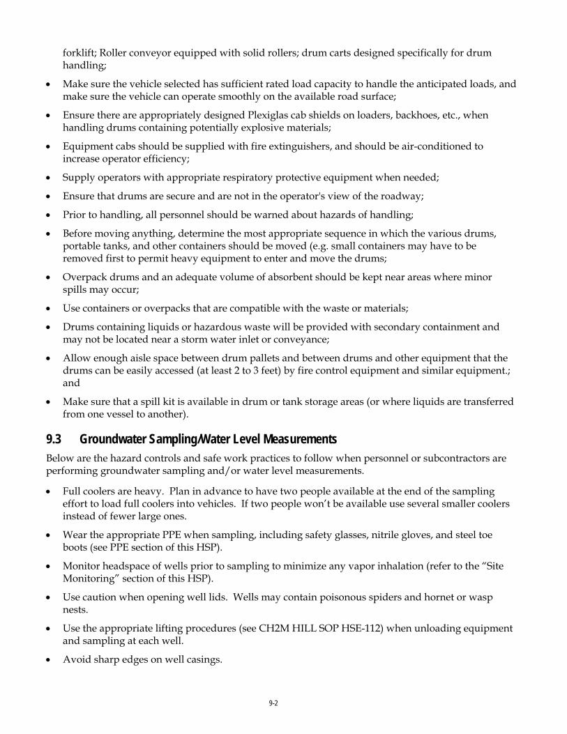
9-2
forklift; Roller conveyor equipped with solid rollers; drum carts designed specifically for drum handling;
• Make sure the vehicle selected has sufficient rated load capacity to handle the anticipated loads, and make sure the vehicle can operate smoothly on the available road surface;
• Ensure there are appropriately designed Plexiglas cab shields on loaders, backhoes, etc., when handling drums containing potentially explosive materials;
• Equipment cabs should be supplied with fire extinguishers, and should be air-conditioned to increase operator efficiency;
• Supply operators with appropriate respiratory protective equipment when needed;
• Ensure that drums are secure and are not in the operator's view of the roadway;
• Prior to handling, all personnel should be warned about hazards of handling;
• Before moving anything, determine the most appropriate sequence in which the various drums, portable tanks, and other containers should be moved (e.g. small containers may have to be removed first to permit heavy equipment to enter and move the drums;
• Overpack drums and an adequate volume of absorbent should be kept near areas where minor spills may occur;
• Use containers or overpacks that are compatible with the waste or materials;
• Drums containing liquids or hazardous waste will be provided with secondary containment and may not be located near a storm water inlet or conveyance;
• Allow enough aisle space between drum pallets and between drums and other equipment that the drums can be easily accessed (at least 2 to 3 feet) by fire control equipment and similar equipment.; and
• Make sure that a spill kit is available in drum or tank storage areas (or where liquids are transferred from one vessel to another).
9.3 Groundwater Sampling/Water Level Measurements Below are the hazard controls and safe work practices to follow when personnel or subcontractors are performing groundwater sampling and/or water level measurements.
• Full coolers are heavy. Plan in advance to have two people available at the end of the sampling effort to load full coolers into vehicles. If two people won’t be available use several smaller coolers instead of fewer large ones.
• Wear the appropriate PPE when sampling, including safety glasses, nitrile gloves, and steel toe boots (see PPE section of this HSP).
• Monitor headspace of wells prior to sampling to minimize any vapor inhalation (refer to the “Site Monitoring” section of this HSP).
• Use caution when opening well lids. Wells may contain poisonous spiders and hornet or wasp nests.
• Use the appropriate lifting procedures (see CH2M HILL SOP HSE-112) when unloading equipment and sampling at each well.
• Avoid sharp edges on well casings.

9-3
• If dermal contact occurs with groundwater or the acid used in sample preservation, immediately wash all affected skin thoroughly with soap and water.
• Avoid eating and drinking on site and during sampling.
• Use ear plugs during sampling if sampling involves a generator.
• Containerize all purge water and transport to the appropriate storage area.
• Use two people to transport full coolers/containers whenever possible. If two people are not available use a dolly to move coolers. If the coolers weigh more than 40 pounds Attachment 1 of the HSE-112, Manual Lifting, shall be completed by the SC. If the coolers weigh more than 50 pounds they should never be lifted by one person.
9.4 Hand and Power Tools (Reference CH2M HILL, SOP HSE-210, Hand and Power Tools)
Below are the hazard controls and safe work practices to follow when personnel or subcontractors are using hand and power tools. Ensure the requirements in the referenced SOP are followed:
• Tools shall be inspected prior to use and damaged tools will be tagged and removed from service;
• Hand tools will be used for their intended use and operated in accordance with manufacturer’s instructions and design limitations;
• Maintain all hand and power tools in a safe condition;
• Use PPE (such as gloves, safety glasses, earplugs, and face shields) when exposed to a hazard from a tool;
• Do not carry or lower a power tool by its cord or hose;
• Portable power tools will be plugged into GFCI protected outlets;
• Portable power tools will be Underwriters Laboratories (UL) listed and have a three-wire grounded plug or be double insulated;
• Disconnect tools from energy sources when they are not in use, before servicing and cleaning them, and when changing accessories (such as blades, bits, and cutters);
• Safety guards on tools must remain installed while the tool is in use and must be promptly replaced after repair or maintenance has been performed;
• Store tools properly in a place where they will not be damaged or come in contact with hazardous materials;
• If a cordless tool is connected to its recharge unit, both pieces of equipment must conform strictly with electrical standards and manufacturer’s specifications;
• Tools used in an explosive environment must be rated for work in that environment (that is, intrinsically safe, spark-proof, etc.); and
• Working with manual and pistol-grip hand tools may involve highly repetitive movement, extended elevation, constrained postures, and/or awkward positioning of body members (for example, hand, wrist, arm, shoulder, neck, etc.). Consider alternative tool designs, improved posture, the selection of appropriate materials, changing work organization, and sequencing to prevent muscular, skeletal, repetitive motion, and cumulative trauma stressors.

9-4
Machine Guarding
• Ensure that all machine guards are in place to prevent contact with drive lines, belts, chains, pinch points or any other sources of mechanical injury.
• Unplugging jammed equipment will only be performed when equipment has been shut down, all sources of energy have been isolated and equipment has been locked/tagged and tested.
• Maintenance and repair of equipment that results in the removal of guards or would otherwise put anyone at risk requires lockout of that equipment prior to work.
9.5 Traffic Control (Reference CH2M HILL SOP HSE-216, Traffic Control)
The following precautions must be taken when working around traffic, and in or near an area where traffic controls have been established by a sub contractor. Ensure the requirements in the referenced SOP are followed.
• Exercise caution when exiting traveled way or parking along street – avoid sudden stops, use flashers, etc.
• Park in a manner that will allow for safe exit from vehicle, and where practicable, park vehicle so that it can serve as a barrier.
• All staff working adjacent to traveled way or within work area must wear reflective/high-visibility safety vests.
• Eye protection should be worn to protect from flying debris.
• Remain aware of factors that influence traffic related hazards and required controls – sun glare, rain, wind, flash flooding, limited sight-distance, hills, curves, guardrails, width of shoulder (i.e., breakdown lane), etc.
• Always remain aware of an escape route (e.g., behind an established barrier, parked vehicle, guardrail, etc).
• Always pay attention to moving traffic – never assume drivers are looking out for you.
• Work as far from traveled way as possible to avoid creating confusion for drivers.
• When workers must face away from traffic, a “buddy system” should be used, where one worker is looking towards traffic.
• When working on highway projects, obtain a copy of the contractor’s traffic control plan.
• Work area should be protected by a physical barrier – such as a K-rail or Jersey barrier.
• Review traffic control devices to ensure that they are adequate to protect your work area. Traffic control devices should: 1) convey a clear meaning, 2) command respect of road users, and 3) give adequate time for proper traffic response. The adequacy of these devices are dependent on limited sight distance, proximity to ramps or intersections, restrictive width, duration of job, and traffic volume, speed, and proximity.
• Either a barrier or shadow vehicle should be positioned a considerable distance ahead of the work area. The vehicle should be equipped with a flashing arrow sign and truck-mounted crash cushion (TMCC). All vehicles within 40 feet (12.2 meters) of traffic should have an orange flashing hazard light atop the vehicle.

9-5
• Except on highways, flaggers should be used when 1) two-way traffic is reduced to using one common lane, 2) driver visibility is impaired or limited, 3) project vehicles enter or exit traffic in an unexpected manner, or 4) the use of a flagger enhances established traffic warning systems.
• Lookouts should be used when physical barriers are not available or practical. The lookout continually watches approaching traffic for signs of erratic driver behavior and warns workers.
• Vehicles should be parked at least 40 feet (12.2 meters) away from the work zone and traffic. Minimize the amount of time that you will have your back to oncoming traffic.
• Traffic control training module on the VO shall be completed when CH2M HILL workers who work in and around roadways and who exposed to public vehicular traffic.
9.6 Utilities (overhead)
Proximity to Power Lines No work is to be conducted within 50 feet (15.2 meters) of overhead power lines without first contacting the utility company to determine the voltage of the system. No aspect of any piece of equipment is to be operated within 50 feet (15.2 meters) of overhead power lines without first making this determination.
Operations adjacent to overhead power lines are PROHIBITED unless one of the following conditions is satisfied:
• Power has been shut off, positive means (such as lockout) have been taken to prevent the lines from being energized, lines have been tested to confirm the outage, and the utility company has provided a signed certification of the outage.
• The minimum clearance from energized overhead lines is as shown in the table below, or the equipment will be repositioned and blocked to ensure that no part, including cables, can come within the minimum clearances shown in the table.
MINIMUM DISTANCES FROM POWERLINES
Powerlines Nominal System Kv Minimum Required Distance, Feet (Meters)
0-50 10 (3.0) 50-200 15 (4.6) 201-350 20 (6.1) 351-500 25 (7.6) 501-750 35 (10.7) 751-1000 45 (13.7)
Over 1000 Established by utility owner/operator or by a professional engineer in electrical
power transmission/distribution (These distances have been determined to eliminate the potential for arcing based on the line voltage.)
• The power line(s) has been isolated through the use of insulating blankets which have been properly placed by the utility. If insulating blankets are used, the utility will determine the minimum safe operating distance; get this determination in writing with the utility representative's signature.
• All inquiries regarding electric utilities must be made in writing and a written confirmation of the outage/isolation must be received by the PM prior to the start of work.

9-6
9.7 Vinyl Chloride (Reference CH2M HILL, SOP HSE-512, Vinyl Chloride)
Vinyl Chloride is considered a “Confirmed Human Carcinogen.” Vinyl Chloride has a mild, sweet, chloroform-like odor.
CH2M HILL is required to control employee workplace exposure to vinyl chloride when personal exposures are at or above 1.0 ppm as an 8-hour time-weighted average (TWA) or above 5.0 ppm short term exposure limit (STEL), by implementing a program that meets the requirements of the Occupational Safety and Health Administration (OSHA) Vinyl Chloride standard, 29 CFR 1910.1017. The elements of the CH2M HILL vinyl chloride program include the following:
• Exposure monitoring
• Methods of control, including personal protective equipment (PPE) and respirators
• Medical surveillance
• Training on hazards of vinyl chloride and control measures (includes project-specific training and the computer-based training on CH2M HILL’s Virtual Office, Vinyl Chloride)
• Record keeping requirements
If air monitoring indicates there is potential exposure at the action level concentrations above, notify the RHSM to ensure the above have been adequately addressed. Other exposure control measures include:
• Do not enter regulated work areas unless training, medical monitoring, and PPE requirements established by the competent person have been met.
• Do not eat, drink, smoke, chew tobacco or gum, or apply cosmetics in regulated areas.
• Respiratory protection and other exposure controls selection shall be based on the most recent exposure monitoring results obtained from the competent person.
• Review the fact sheet included as an attachment to this HSP.
9.8 Working Around Material Handling Equipment When CH2M HILL personnel are exposed to material handling equipment, the following safe work practices/hazard controls shall be implemented:
• Never approach operating equipment from the rear. Always make positive contact with the operator, and confirm that the operator has stopped the motion of the equipment.
• Never approach the side of operating equipment; remain outside of the swing and turning radius.
• Maintain distance from pinch points of operating equipment.
• Never turn your back on any operating equipment.
• Never climb onto operating equipment or operate contractor/subcontractor equipment.
• Never ride contractor/subcontractor equipment unless it is designed to accommodate passengers and equipped with firmly attached passenger seat.
• Never work or walk under a suspended load.
• Never use equipment as a personnel lift; do not ride excavator buckets or crane hooks.
• Always stay alert and maintain a safe distance from operating equipment, especially equipment on cross slopes and unstable terrain.
9-7
• Wear a high visibility safety vest or high visibility clothing
9.9 Working Alone Personnel can only be tasked to work alone by the Project Manager who shall assess potential hazards and appropriate control measures, with assistance from the Responsible Health and Safety Manager (RHSM).
“Lone workers” with an accountability system in place is permitted, depending on the hazards presented during the execution of the task. Reference the “Lone Worker Protocol” included as an attachment to this HSP.
Only limited operations task are permitted to be performed alone. Activities that are not permitted to be performed by a lone worker include the following:
• Working at heights (e.g., on ladders, lifts, scaffolding);
• Energy isolation (e.g., lockout/tagout);
• Any entry into a confined space; and
• Work involving electricity or other hazardous equipment (e.g., chainsaws);
• Work over or near water; and
• Working in an area where there is an increased potential for violence.
An AHA shall be developed that shall include:
• Type or nature of work to be conducted by the lone worker;
• Location of the work
• Length of time the worker will be working alone; and
• Any characteristics of the individual working alone which may increase the risk to the worker (e.g., medical conditions).
The employee working alone shall at all times be equipped with a working voice communication device such as a cellular phone, satellite phone, personal alarms, or two-way radio to check-in to their project contact (s) at pre-determined times. For some work, a satellite-based communication system may be appropriate (i.e., a “SPOT” device).
Satellite-Based Communication System for Lone Worker Accountability
Call-In System for Lone Worker Accountability The employee working alone shall at all times be equipped with a working voice communication device such as a cellular phone, satellite phone, personal alarms, or two-way radio to check-in to their project contact (s) at pre-determined times.
Each time before going into the field, the “Call in contact Form” attached to this HSP shall be completed by the lone worker and given to the call-in office worker contact prior to going into the field.
During field work, a copy of “The Lone Worker Call-In Contact Form” should be maintained by both the “Office Contact Worker” and the field-worker (“Lone Worker”). Lone Worker and Office Contact Worker must both have cell phones and each others’ phone number, plus one other alternate phone number.

9-8
Lone worker shall call the office contact worker when he/she has arrived on-site, before exiting his/her vehicle. On this phone call, a time shall be arranged for a “check-in” call to be made by the field worker, based on duration of task. On each “check-in” call a time should be arranged for the next “check-in” call. Document these times on the form.
Lone Worker shall carry his or her cell-phone throughout the field event and put the ringer on its loudest setting as wind or other noise can muffle the sound. If, for any reason the cell-phone becomes inoperable, the field-worker shall immediately stop work, leave the site and find an alternative method of contacting the Office Contact Worker to verify their safety and to inform them of the issue.
Work shall not proceed in the field until the Lone Worker has a working device that provides communication with the Office Contact Worker.
Upon completion of work activities, Lone Worker should pack up all materials and prepare to leave site. Then, before starting the engine of the vehicle to leave site, the Lone Worker should contact the office-worker and inform him or her that work is complete and that he or she is leaving the site. A final call shall be made by the lone work to the office worker to confirm he/she has reached their destination.
If at any time, the Office Contact Worker does not receive a “check-in” call at the scheduled time he/she should attempt to contact Lone Worker. If no contact is made then the Office Contact Worker should contact the facility contact person to check on the Lone Worker.
If no contact is made with the Lone Worker, then the Office Contact Worker shall contact the PM and/or RHSM to let them know they are going to inform emergency services inform that there is a possible emergency and instruct them to go to the field location and assist the Lone Worker. The Office Contact Worker will provide to emergency services the Lone Worker’s name, their last known location, vehicle description and their contact information.
Call in contact Form shall be completed by lone worker and given to call in contact prior to going into the field. Refer to the “Lone Worker Protocol” attached to this HSP.

10-1
10.0 Physical Hazards and Controls Physical hazards include exposure to temperature extremes, sun, noise, and radiation. If you encounter a physical hazard that has not been identified in this plan, contact the RHSM so that a revision to this plan can be made.
10.1 Noise (Reference CH2M HILL SOP HSE-108, Hearing Conservation)
CH2M HILL is required to control employee exposure to occupational noise levels of 85 decibels, A-weighted, (dBA) and above by implementing a hearing conservation program that meets the requirements of the OSHA Occupational Noise Exposure standard, 29 CFR 1910.95. A noise assessment may be conducted by the RHSM or designee based on potential to emit noise above 85 dBA and also considering the frequency and duration of the task.
• Areas or equipment emitting noise at or above 90dBA shall be evaluated to determine feasible engineering controls. When engineering controls are not feasible, administrative controls can be developed and appropriate hearing protection will be provided.
• Areas or equipment emitting noise levels at or above 85 dBA, hearing protection must be worn.
• Employees exposed to 85 dBA or a noise dose of 50% must participate in the Hearing Conservation program including initial and annual (as required) audiograms.
• The RHSM will evaluate appropriate controls measures and work practices for employees who have experienced a standard threshold shift (STS) in their hearing.
• Employees who are exposed at or above the action level of 85 dBA are required to complete the online Noise Training Module located on CH2M HILL’s virtual office.
• Hearing protection will be maintained in a clean and reliable condition, inspected prior to use and after any occurrence to identify any deterioration or damage, and damaged or deteriorated hearing protection repaired or discarded.
• In work areas where actual or potential high noise levels are present at any time, hearing protection must be worn by employees working or walking through the area.
• Areas where tasks requiring hearing protection are taking place may become hearing protection required areas as long as that specific task is taking place.
• High noise areas requiring hearing protection should be posted or employees must be informed of the requirements in an equivalent manner and a copy of the OSHA standard 29 CFR 1910.95 shall be posted in the workplace.
10.2 Ultraviolet Radiation (sun exposure) Health effects regarding ultraviolet (UV) radiation are confined to the skin and eyes. Overexposure can result in many skin conditions, including erythema (redness or sunburn), photoallergy (skin rash), phototoxicity (extreme sunburn acquired during short exposures to UV radiation while on certain medications), premature skin aging, and numerous types of skin cancer. Implement the following controls to avoid sunburn.
Limit Exposure Time
• Rotate staff so the same personnel are not exposed all of the time.

10-2
• Limit exposure time when UV radiation is at peak levels (approximately 2 hours before and after the sun is at its highest point in the sky).
• Avoid exposure to the sun, or take extra precautions when the UV index rating is high.
Provide Shade
• Take lunch and breaks in shaded areas.
• Create shade or shelter through the use of umbrellas, tents, and canopies.
• Fabrics such as canvas, sailcloth, awning material and synthetic shade cloth create good UV radiation protection.
• Check the UV protection of the materials before buying them. Seek protection levels of 95 percent or greater, and check the protection levels for different colors.
Clothing
• Reduce UV radiation damage by wearing proper clothing; for example, long sleeved shirts with collars, and long pants. The fabric should be closely woven and should not let light through.
• Head protection should be worn to protect the face, ears, and neck. Wide-brimmed hats with a neck flap or “Foreign Legion” style caps offer added protection.
• Wear UV-protective sunglasses or safety glasses. These should fit closely to the face. Wrap-around style glasses provide the best protection.
Sunscreen
• Apply sunscreen generously to all exposed skin surfaces at least 20 minutes before exposure, allowing time for it to adhere to the skin.
• Re-apply sunscreen at least every 2 hours, and more frequently when sweating or performing activities where sunscreen may be wiped off.
• Choose a sunscreen with a high sun protection factor (SPF). Most dermatologists advocate SPF 30 or higher for significant sun exposure.
• Waterproof sunscreens should be selected for use in or near water, and by those who perspire sufficiently to wash off non-waterproof products.
• Check for expiration dates, because most sunscreens are only good for about 3 years. Store in a cool place out of the sun.
• No sunscreen provides 100 percent protection against UV radiation. Other precautions must be taken to avoid overexposure.
10.3 Temperature Extremes (Reference CH2M HILL SOP HSE-211, Heat and Cold Stress)
Each employee is responsible for the following:
• Recognizing the symptoms of heat or cold stress;
• Taking appropriate precautionary measures to minimize their risk of exposure to temperature extremes (see following sections); and
• Communicating any concerns regarding heat and cold stress to their supervisor or SC.

10-3
10.3.1 Heat Heat-related illnesses are caused by more than just temperature and humidity factors.
Physical fitness influences a person's ability to perform work under heat loads. At a given level of work, the more fit a person is, the less the physiological strain, the lower the heart rate, the lower the body temperature (indicates less retrained body heat—a rise in internal temperature precipitates heat injury), and the more efficient the sweating mechanism.
Acclimatization is the degree to which a worker's body has physiologically adjusted or acclimatized to working under hot conditions. Acclimatization affects their ability to do work. Acclimatized individuals sweat sooner and more profusely than un-acclimatized individuals. Acclimatization occurs gradually over 1 to 2 weeks of continuous exposure, but it can be lost in as little as 3 days in a cooler environment.
Dehydration reduces body water volume. This reduces the body’s sweating capacity and directly affects its ability to dissipate excess heat.
The ability of a body to dissipate heat depends on the ratio of its surface area to its mass (surface area/weight). Heat dissipation is a function of surface area, while heat production depends on body mass. Therefore, overweight individuals (those with a low ratio) are more susceptible to heat-related illnesses because they produce more heat per unit of surface area than if they were thinner. Monitor these persons carefully if heat stress is likely.
When wearing impermeable clothing, the weight of an individual is not as important in determining the ability to dissipate excess heat because the primary heat dissipation mechanism, evaporation of sweat, is ineffective.
SYMPTOMS AND TREATMENT OF HEAT STRESS
Heat Syncope Heat Rash Heat Cramps Heat Exhaustion Heat Stroke
Signs and Symptoms
Sluggishness or fainting while standing erect or immobile in heat.
Profuse tiny raised red blister-like vesicles on affected areas, along with prickling sensations during heat exposure.
Painful spasms in muscles used during work (arms, legs, or abdomen); onset during or after work hours.
Fatigue, nausea, headache, giddiness; skin clammy and moist; complexion pale, muddy, or flushed; may faint on standing; rapid thready pulse and low blood pressure; oral temperature normal or low
Red, hot, dry skin; dizziness; confusion; rapid breathing and pulse; high oral temperature.
Treatment Remove to cooler area. Rest lying down. Increase fluid intake. Recovery usually is prompt and complete.
Use mild drying lotions and powders, and keep skin clean for drying skin and preventing infection.
Remove to cooler area. Rest lying down. Increase fluid intake.
Remove to cooler area. Rest lying down, with head in low position. Administer fluids by mouth. Seek medical attention.
Cool rapidly by soaking in cool–but not cold–water. Call ambulance, and get medical attention immediately!
Precautions
• Drink 16 ounces of water before beginning work. Disposable cups and water maintained at 50oFahrenheit (10 degrees Celsius [C]) to 60oFahrenheit (F) (15.6 degrees C) should be available. Under severe conditions, drink 1 to 2 cups every 20 minutes, for a total of 1 to 2 gallons (7.5 liters) per day. Do not use alcohol in place of water or other nonalcoholic fluids. Decrease your intake of coffee and caffeinated soft drinks during working hours.
• Acclimate yourself by slowly increasing workloads (do not begin with extremely demanding activities).

10-4
• Use cooling devices, such as cooling vests, to aid natural body ventilation. These devices add weight, so their use should be balanced against efficiency.
• Use mobile showers or hose-down facilities to reduce body temperature and cool protective clothing.
• Conduct field activities in the early morning or evening and rotate shifts of workers, if possible.
• Avoid direct sun whenever possible, which can decrease physical efficiency and increase the probability of heat stress. Take regular breaks in a cool, shaded area. Use a wide-brim hat or an umbrella when working under direct sun for extended periods.
• Provide adequate shade to protect personnel against radiant heat (sun, flames, hot metal).
• Maintain good hygiene standards by frequently changing clothing and showering.
• Observe one another for signs of heat stress. PREVENTION and communication is key.
Thermal Stress Monitoring
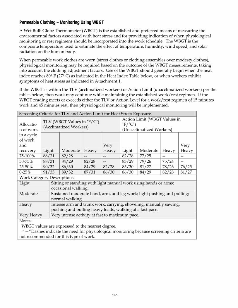
10-5
Permeable Clothing – Monitoring Using WBGT A Wet Bulb Globe Thermometer (WBGT) is the established and preferred means of measuring the environmental factors associated with heat stress and for providing indication of when physiological monitoring or rest regimens should be incorporated into the work schedule. The WBGT is the composite temperature used to estimate the effect of temperature, humidity, wind speed, and solar radiation on the human body.
When permeable work clothes are worn (street clothes or clothing ensembles over modesty clothes), physiological monitoring may be required based on the outcome of the WBGT measurements, taking into account the clothing adjustment factors. Use of the WBGT should generally begin when the heat index reaches 80° F (27° C) as indicated in the Heat Index Table below, or when workers exhibit symptoms of heat stress as indicated in Attachment 1.
If the WBGT is within the TLV (acclimatized workers) or Action Limit (unacclimatized workers) per the tables below, then work may continue while maintaining the established work/rest regimen. If the WBGT reading meets or exceeds either the TLV or Action Level for a work/rest regimen of 15 minutes work and 45 minutes rest, then physiological monitoring will be implemented.
Screening Criteria for TLV and Action Limit for Heat Stress Exposure Allocation of work in a cycle of work and recovery
TLV (WBGT Values in ˚F/C˚) (Acclimatized Workers)
Action Limit (WBGT Values in ˚F/˚C˚) (Unacclimatized Workers)
Light Moderate Heavy Very Heavy Light Moderate Heavy
Very Heavy
75-100% 88/31 82/28 -- -- 82/28 77/25 -- -- 50-75% 88/31 84/29 82/28 -- 83/29 79/26 75/24 -- 25-50% 90/32 86/30 84/29 82/28 85/30 81/27 78/26 76/25 0-25% 91/33 89/32 87/31 86/30 86/30 84/29 82/28 81/27 Work Category Descriptions: Light Sitting or standing with light manual work using hands or arms;
occasional walking. Moderate Sustained moderate hand, arm, and leg work; light pushing and pulling;
normal walking. Heavy Intense arm and trunk work, carrying, shoveling, manually sawing,
pushing and pulling heavy loads, walking at a fast pace. Very Heavy Very intense activity at fast to maximum pace. Notes: WBGT values are expressed to the nearest degree. “—“Dashes indicate the need for physiological monitoring because screening criteria are not recommended for this type of work.

10-6
Clothing Adjustment Factors for Some Clothing Ensembles* Clothing Type Addition to WBGT ˚F/˚C˚ Work Clothes (sleeved shirt and pants) 0/0 Cloth (woven material) coveralls 0/0 Double-layer woven clothing 5.4/3 Polypropylene coveralls 0.9/0.5 Limited Use Vapor barrier coveralls 19.8/11 * These values must not be used for completely encapsulating (impermeable) coveralls/suits. Coveralls assume that only modesty clothing is worn beneath.
Thermal Stress Monitoring – Permeable or Impermeable Clothing When permeable work clothes are worn (street clothes or clothing ensembles over street clothes), regularly observe workers for signs and symptoms of heat stress and implement physiological monitoring as indicated below. This should start when the heat index reaches 80° F (27° C) [see Heat Index Table below], or sooner if workers exhibit symptoms of heat stress indicated in the table above. These heat index values were devised for shady, light wind conditions; exposure to full sunshine can increase the values by up to 15°F (8°C). Also, strong winds, particularly with very hot, dry air, can be extremely hazardous.
When wearing impermeable clothing (e.g., clothing doesn’t allow for air or water vapor movement such as Tyvek), physiological monitoring as described below shall be conducted when the ambient temperature reaches 70° F (21° C) or at a lower temperature when workers begin to exhibit signs and symptoms of heat stress.
Heat Index Possible Heat Disorders Minimum Frequency of Physiological Monitoring
80°F - 90°F (27°C - 32°C)
Fatigue possible with prolonged exposure and/or physical activity
Observe Workers for signs of heat stress and implement physiological monitoring if warranted.
90°F - 105°F (32°C - 41°C)
Sunstroke, heat cramps, or heat exhaustion possible with prolonged exposure and/or physical activity
Every 2 hours, or sooner, if signs of heat stress are observed.
105°F - 130°F (41°C - 54°C)
Sunstroke, heat cramps, or heat exhaustion likely, and heat stroke possible with prolonged exposure and/or physical activity.
Every 60 minutes or sooner if signs of heat stress are observed.
130°F or Higher (54°C or Higher)
Heat/Sunstroke highly likely with continued exposure.
Every 30 minutes or sooner if signs of heat stress are observed.
Source: National Weather Service
Physiological Monitoring and Associated Actions The following physiological monitoring protocol below, using either radial pulse or aural temperature, will occur when the heat index is 80 degrees F or greater (or when personnel exhibit signs of heat stress), the following will be performed:
• The sustained heart rate during the work cycle should remain below 180 beats per minute (bpm) minus the individual’s age (e.g. 180 – 35 year old person = 145 bpm). The sustained heart rate can be estimated by measuring the heart rate at the radial pulse for 30 seconds as quickly as possible prior to starting the rest period.

10-7
• The heart rate after one minute rest period should not exceed 120 beats per minute (bpm).
• If the heart rate is higher than 120 bpm, the next work period should be shortened by 33 percent, while the length of the rest period stays the same.
• If the pulse rate still exceeds 120 bpm at the beginning of the next rest period, the following work cycle should be further shortened by 33 percent.
• Continue this procedure until the rate is maintained below 120 bpm.
• Alternately, the body temperature can be measured, either oral or aural (ear), before the workers have something to drink.
• If the oral or aural temperature exceeds 99.6° F (37.6 ° F) at the beginning of the rest period, the following work cycle should be shortened by 33 percent.
• Continue this procedure until the oral or aural (ear) temperature is maintained below 99.6 ° F (37.6° C). While an accurate indication of heat stress, oral temperature is difficult to measure in the field, however, a digital aural (aural) thermometer is easy to obtain and inexpensive to purchase.
• Use the form attached to this HSP to track workers’ measurements and actions taken.
Procedures for when Heat Illness Symptoms are Experienced
• Always contact the RHSM when any heat illness related symptom is experienced so that controls can be evaluated and modified, if needed.
• In the case of cramps, reduce activity, increase fluid intake, move to shade until recovered.
• In the case of all other heat-related symptoms (fainting, heat rash, heat exhaustion), and if the worker is a CH2M HILL worker, contact the occupational physician at 1-866-893-2514 and immediate supervisor.
• In the case of heat stroke symptoms, call 911, have a designee give location and directions to ambulance service if needed, follow precautions under the emergency medical treatment of this HSP.
• Follow the Incident Notification, Reporting, and Investigation section of this HSP.
10.3.2 Cold
General Low ambient temperatures increase the heat lost from the body to the environment by radiation and convection. In cases where the worker is standing on frozen ground, the heat loss is also due to conduction.
Wet skin and clothing, whether because of water or perspiration, may conduct heat away from the body through evaporative heat loss and conduction. Thus, the body cools suddenly when chemical protective clothing is removed if the clothing underneath is perspiration soaked.
Movement of air across the skin reduces the insulating layer of still air just at the skin’s surface. Reducing this insulating layer of air increases heat loss by convection.
Non-insulating materials in contact or near-contact with the skin, such as boots constructed with a metal toe or shank, conduct heat rapidly away from the body.

10-8
Certain common drugs, such as alcohol, caffeine, or nicotine, may exacerbate the effects of cold, especially on the extremities. These chemicals reduce the blood flow to peripheral parts of the body, which are already high-risk areas because of their large surface area to volume ratios. These substances may also aggravate an already hypothermic condition.
Precautions
• Be aware of the symptoms of cold-related disorders, and wear proper, layered clothing for the anticipated fieldwork. Appropriate rain gear is a must in wet weather.
• Consider monitoring the work conditions and adjusting the work schedule using guidelines developed by the U.S. Army (wind-chill index) and the National Safety Council (NSC).
• Wind-Chill Index (below) is used to estimate the combined effect of wind and low air temperatures on exposed skin. The wind-chill index does not take into account the body part that is exposed, the level of activity, or the amount or type of clothing worn. For those reasons, it should only be used as a guideline to warn workers when they are in a situation that can cause cold-related illnesses.
• Persons who experience initial signs of immersion foot, frostbite, and/or hypothermia should report it immediately to their supervisor/PM to avoid progression of cold-related illness.
• Observe one another for initial signs of cold-related disorders.
• Obtain and review weather forecast – be aware of predicted weather systems along with sudden drops in temperature, increase in winds, and precipitation.
SYMPTOMS AND TREATMENT OF COLD STRESS
Immersion (Trench) Foot
Frostbite Hypothermia
Signs and Symptoms
Feet discolored and painful; infection and swelling present.
Blanched, white, waxy skin, but tissue resilient; tissue cold and pale.
Shivering, apathy, sleepiness; rapid drop in body temperature; glassy stare; slow pulse; slow respiration.
Treatment Seek medical treatment immediately.
Remove victim to a warm place. Re-warm area quickly in warm–but not hot–water. Have victim drink warm fluids, but not coffee or alcohol. Do not break blisters. Elevate the injured area, and get medical attention.
Remove victim to a warm place. Have victim drink warm fluids, but not coffee or alcohol. Get medical attention.

10-9
10.4 Radiological Hazards Refer to CH2M HILL’s Core Standard, Radiological Control and Radiological Controls Manual for additional requirements.
Hazards Controls
None Known None Required

11-1
11.0 Biological Hazards and Controls Biological hazards are everywhere and change with the region and season. If you encounter a biological hazard that has not been identified in this plan, contact the RHSM so that a revision to this plan can be made. Whether it is contact with a poisonous plant, a poisonous snake, or a bug bite, do not take bites or stings lightly. If there is a chance of an allergic reaction or infection, or to seek medical advice on how to properly care for the injury, contact the occupational nurse at 1-866-893-2514.
11.1 Bees and Other Stinging Insects Bees and other stinging insects may be encountered almost anywhere and may present a serious hazard, particularly to people who are allergic. Watch for and avoid nests. Keep exposed skin to a minimum. Carry a kit if you have had allergic reactions in the past, and inform your supervisor and/or a buddy. If you are stung, contact the occupational nurse at 1-866-893-2514. If a stinger is present, remove it carefully with tweezers. Wash and disinfect the wound, cover it, and apply ice. Watch for an allergic reaction if you have never been stung before. Call 911 if the reaction is severe.
11.2 Feral Dogs Avoid all dogs – both leashed and stray. Do not disturb a dog while it is sleeping, eating, or caring for puppies. If a dog approaches to sniff you, stay still. An aggressive dog has a tight mouth, flattened ears and a direct stare. If you are threatened by a dog, remain calm, do not scream and avoid eye contact. If you say anything, speak calmly and firmly. Do not turn and run, try to stay still until the dog leaves, or back away slowly until the dog is out of sight or you have reached safety (e.g. vehicle). If attacked, retreat to vehicle or attempt to place something between you and the dog. If you fall or are knocked to the ground, curl into a ball with your hands over your head and neck and protect your face. If bitten, contact the occupational nurse at 1-866-893-2514. Report the incident to the local authorities.
11.3 Hazards during Hunting Seasons Various times of the year can be particularly hazardous for personnel working in the field. The danger is highest for our teams doing cross-country surveys of pipelines and transmission lines, but everyone doing field work should be aware of the hunting seasons that are active where you are working.
Big game hunting can be very dangerous, but also be aware of water fowl seasons and hunting seasons for less common game in your area. Work in wetlands can bring us in close proximity to these types of hunters.
If possible consider postponing field surveys so they do not coincide with hunting seasons but if you must be in the field be as visible as possible at all times.
This site gives all the different hunting seasons by state:
www.huntinfo.org/ Implement the following if hunting may be a hazard:
• Do not wear kaki, brown or tan clothing, wear high visibility colors including hats and vests;
• Avoid wearing white or light colored scarves, gloves , handkerchiefs (a woman wearing white mittens hanging laundry was shot and killed as bad hunter shot at flash of white);
• When carrying white plans, field data sheets etc keep them in binder or backpack;
• Wear your safety vest at all times including standing by car/truck;
• Wear a safety hat/cap or put florescent markers on hard hats;

11-2
• Be alert particularly in early mornings and at end of day when most hunters are present;
• Avoid being in field altogether at dawn or dusk - start a little later in the morning and make sure you get out of the field earlier;
• Stop at local hardware or convenience market and pick up hunter safety gloves, caps, rolls of tape etc. All the stores carry them and they are cheap visual protection.
• Make your presence known, such as slamming car doors, honk horn, talk loudly when getting out to a field site; and
• Stop and survey your surroundings. Many hunters are up in tree stands.
11.4 Mosquito Bites Due to the recent detection of the West Nile Virus in the southwestern United States it is recommended that preventative measures be taken to reduce the probability of being bitten by mosquitoes whenever possible. Mosquitoes are believed to be the primary source for exposure to the West Nile Virus as well as several other types of encephalitis. The following guidelines should be followed to reduce the risk of these concerns for working in areas where mosquitoes are prevalent:
• Stay indoors at dawn, dusk, and in the early evening;
• Wear long-sleeved shirts and long pants whenever you are outdoors;
• Spray clothing with repellents containing permethrin or N,N-diethyl-meta-toluamide (DEET) since mosquitoes may bite through thin clothing;
• Apply insect repellent sparingly to exposed skin. An effective repellent will contain 35% DEET. Repellents may irritate the eyes and mouth, so avoid applying repellent to the hands; and
• Whenever you use an insecticide or insect repellent, be sure to read and follow the manufacturer's DIRECTIONS FOR USE, as printed on the product.
Vitamin B and "ultrasonic" devices are NOT effective in preventing mosquito bites.
Symptoms of Exposure to the West Nile Virus Most infections are mild, and symptoms include fever, headache, and body aches, occasionally with skin rash and swollen lymph glands. More severe infection may be marked by headache, high fever, neck stiffness, stupor, disorientation, coma, tremors, convulsions, muscle weakness, paralysis, and, rarely, death.
The West Nile Virus incubation period is from 3 to 15 days.
Contact the project RHSM with questions, and immediately report any suspicious symptoms to your supervisor, PM, and contact the occupational nurse at 1-866-893-2514.
11.5 Poison Ivy, Poison Oak, and Poison Sumac Poison ivy, poison oak, and poison sumac typically are found in brush or wooded areas. They are more commonly found in moist areas or along the edges of wooded areas. Shrubs are usually 12 to 30 inches high, or can also be a tree-climbing vine, with triple leaflets and short, smooth hair underneath. Plants are red and dark green in spring and summer, with yellowing leaves anytime especially in dry areas. Leaves may achieve bright reds in fall, but plants lose its (yellowed, then brown) leaves in winter, leaving toxic stems. All parts of the plant remain toxic throughout the seasons. These plants contain urushiol a colorless or pale yellow oil that oozes from any cut or crushed part of the plant, including the roots, stems and leaves and causes allergic skin reactions when contacted. The oil is active year round.

11-3
Become familiar with the identity of these plants (see below). Wear protective clothing that covers exposed skin and clothes. Avoid contact with plants and the outside of protective clothing. If skin contacts a plant, wash the area with soap and water immediately. If the reaction is severe or worsens, seek medical attention.
Poison Ivy Poison Sumac Poison Oak
Contamination with poison ivy, sumac or oak can happen through several pathways, including:
• Direct skin contact with any part of the plant (even roots once above ground foliage has been removed).
• Contact with clothing that has been contaminated with the oil.
• Contact from removing shoes that have been contaminated (shoes are coated with urishol oil).
• Sitting in a vehicle that has become contaminated.
• Contact with any objects or tools that have become contaminated.
• Inhalation of particles generated by weed whacking, chipping, vegetation clearing.
If you must work on a site with poison ivy, sumac or oak the following precautions are necessary:
• Do not drive vehicles onto the site where it will come into contact with poison ivy, sumac or oak. Vehicles which need to work in the area, such as drill rigs or heavy equipment must be washed as soon as possible after leaving the site.
• All tools used in the poison ivy, sumac or oak area, including those used to cut back poison oak, surveying instruments used in the area, air monitoring equipment or other test apparatus must be decontaminated before they are placed back into the site vehicle. If on-site decontamination is not possible, use plastic to wrap any tools or equipment until they can be decontaminated.
• Personal protective equipment, including Tyvek coveralls, gloves, and boot covers must be worn. PPE must be placed into plastic bags and sealed if they are not disposed immediately into a trash receptacle.
• As soon as possible following the work, shower to remove any potential contamination. Any body part with suspected or actual exposure should be washed with Zanfel, Tecnu or other product designed for removing urushiol. If you do not have Zanfel or Tecnu wash with cold water. Do not take a bath, as the oils can form and invisible film on top of the water and contaminate your entire body upon exiting the bath.
• Tecnu may also be used to decontaminate equipment.
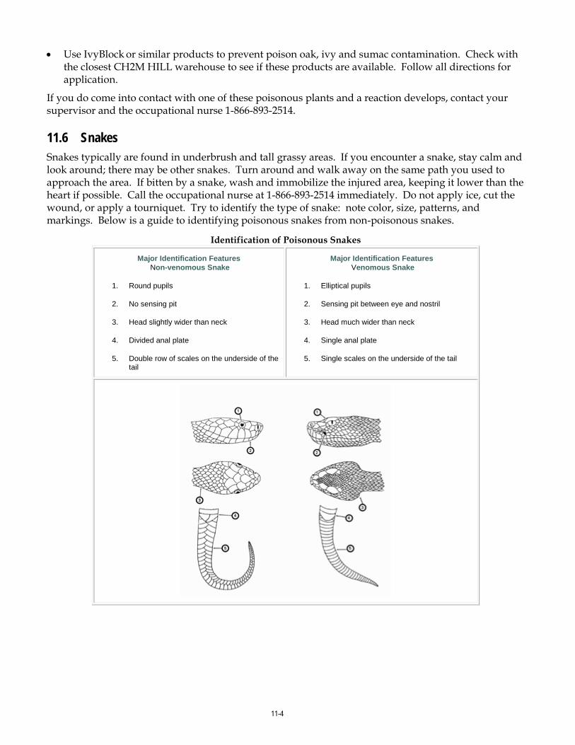
11-4
• Use IvyBlock or similar products to prevent poison oak, ivy and sumac contamination. Check with the closest CH2M HILL warehouse to see if these products are available. Follow all directions for application.
If you do come into contact with one of these poisonous plants and a reaction develops, contact your supervisor and the occupational nurse 1-866-893-2514.
11.6 Snakes Snakes typically are found in underbrush and tall grassy areas. If you encounter a snake, stay calm and look around; there may be other snakes. Turn around and walk away on the same path you used to approach the area. If bitten by a snake, wash and immobilize the injured area, keeping it lower than the heart if possible. Call the occupational nurse at 1-866-893-2514 immediately. Do not apply ice, cut the wound, or apply a tourniquet. Try to identify the type of snake: note color, size, patterns, and markings. Below is a guide to identifying poisonous snakes from non-poisonous snakes.
Identification of Poisonous Snakes
Major Identification Features Non-venomous Snake
1. Round pupils
2. No sensing pit
3. Head slightly wider than neck
4. Divided anal plate
5. Double row of scales on the underside of the tail
Major Identification Features Venomous Snake
1. Elliptical pupils
2. Sensing pit between eye and nostril
3. Head much wider than neck
4. Single anal plate
5. Single scales on the underside of the tail
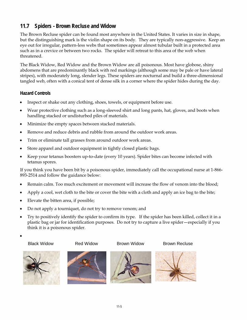
11-5
11.7 Spiders - Brown Recluse and Widow The Brown Recluse spider can be found most anywhere in the United States. It varies in size in shape, but the distinguishing mark is the violin shape on its body. They are typically non-aggressive. Keep an eye out for irregular, pattern-less webs that sometimes appear almost tubular built in a protected area such as in a crevice or between two rocks. The spider will retreat to this area of the web when threatened.
The Black Widow, Red Widow and the Brown Widow are all poisonous. Most have globose, shiny abdomens that are predominantly black with red markings (although some may be pale or have lateral stripes), with moderately long, slender legs. These spiders are nocturnal and build a three-dimensional tangled web, often with a conical tent of dense silk in a corner where the spider hides during the day.
Hazard Controls
• Inspect or shake out any clothing, shoes, towels, or equipment before use.
• Wear protective clothing such as a long-sleeved shirt and long pants, hat, gloves, and boots when handling stacked or undisturbed piles of materials.
• Minimize the empty spaces between stacked materials.
• Remove and reduce debris and rubble from around the outdoor work areas.
• Trim or eliminate tall grasses from around outdoor work areas.
• Store apparel and outdoor equipment in tightly closed plastic bags.
• Keep your tetanus boosters up-to-date (every 10 years). Spider bites can become infected with tetanus spores.
If you think you have been bit by a poisonous spider, immediately call the occupational nurse at 1-866-893-2514 and follow the guidance below:
• Remain calm. Too much excitement or movement will increase the flow of venom into the blood;
• Apply a cool, wet cloth to the bite or cover the bite with a cloth and apply an ice bag to the bite;
• Elevate the bitten area, if possible;
• Do not apply a tourniquet, do not try to remove venom; and
• Try to positively identify the spider to confirm its type. If the spider has been killed, collect it in a plastic bag or jar for identification purposes. Do not try to capture a live spider—especially if you think it is a poisonous spider.
•
Black Widow Red Widow Brown Widow Brown Recluse

11-6
11.8 Ticks Every year employees are exposed to tick bites at work and at home putting them at risk of illness. Ticks typically are in wooded areas, bushes, tall grass, and brush. Ticks are black, black and red, or brown and can be up to one-quarter inch (6.4 mm) in size.
In some geographic areas exposure is not easily avoided. Wear tightly woven light-colored clothing with long sleeves and pant legs tucked into boots; spray only outside of clothing with permethrin or permanone and spray skin with only DEET; and check yourself frequently for ticks.
Where site conditions (vegetation above knee height, tick endemic area) or when tasks (having to sit or kneel in vegetation) diminish the effectiveness of the other controls mentioned above, bug-out suits (check with your local or regional warehouse) or Tyvek shall be used. Bug-out suits are more breathable than Tyvek.
Take precautions to avoid exposure by including pre-planning measures for biological hazards prior to starting field work. Avoid habitats where possible, reduce the abundance through habitat disruption or application of acracide. If these controls aren’t feasible, contact your local or regional warehouse for preventative equipment such as repellants, protective clothing and tick removal kits. Use the buddy system and perform tick inspections prior to entering the field vehicle. If ticks were not planned to be encountered and are observed, do not continue field work until these controls can be implemented.

11-7
See Tick Fact Sheet attached to this HSP for further precautions and controls to implement when ticks are present. If bitten by a tick, follow the removal procedures found in the tick fact sheet, and call the occupational nurse at 1-866-893-2514.
Be aware of the symptoms of Lyme disease or Rocky Mountain spotted fever (RMSF). Lyme disease is a rash that might appear that looks like a bullseye with a small welt in the center. RMSF is a rash of red spots under the skin 3 to 10 days after the tick bite. In both RMSF and Lyme disease, chills, fever, headache, fatigue, stiff neck, and bone pain may develop. If symptoms appear, again contact the occupational nurse at 1-866-893-2514.
Be sure to complete an Incident Report (either use the Hours and Incident Tracking System [HITS] system on the VO) if you do come in contact with a tick.

12-1
12.0 Contaminants of Concern The table below summarizes the potential contaminants of concern (COC) and their occupational exposure limit and signs and symptoms of exposure. The table also includes the maximum concentration of each COC and the associated location and media that was sampled (groundwater, soil boring, surface soil). These concentrations were used to determine engineering and administrative controls described in the “Project-Specific Hazard Controls” section of this HSP, as well as PPE and site monitoring requirements.
Contaminants of Concern Contaminant Location and Maximuma
Concentration (ppm) Exposure Limitb
IDLHc
Symptoms and Effects of Exposure
PIPd
(eV) Benzene GW: 2,700 at Site 78 0.5 ppm 500
Ca Eye, nose, skin, and respiratory irritation; headache; nausea; dermatitis; fatigue; giddiness; staggered gait; bone marrow depression 9.24
1,2-Dichloroethene (total)
GW: 7,900 Site 78
200 ppm 3,000 CNS depression, skin irritation; liver, kidney, and lung damage 11.06
Ethyl Benzene GW: 1,700 at Site 78 100 ppm 800 Eye, skin, and mucous membrane irritation; headache; dermatitis; narcotic; coma
8.76
1,1,2,2-Tetrachloroethane (PCA)
GW: 17,000 at Site 6 1 ppm 100 Ca
Nausea, vomiting, abdominal pain, finger tremors, jaundice, hepatitis, liver tenderness, monocytosis, kidney damage, dermatitis
11.10
Trichloroethylene (TCE) GW: 9,000 at Site 6 10 ppm 1,000 Ca
Headache, vertigo, visual disturbance, eye and skin irritation, fatigue, giddiness, tremors, sleepiness, nausea, vomiting, dermatitis, cardiac arrhythmia, paresthesia, liver injury
9.45
Toluene GW: 11,000 at Site 78 20 ppm 500
Eye and nose irritation, fatigue, weakness, confusion, dizziness, headache, dilated pupils, excessive tearing, nervousness, muscle fatigue, paresthesia, dermatitis, liver and kidney damage
8.82
Xylenes GW: 6,000 at Site 78 100 ppm 900 Irritated eyes, skin, nose, and throat; dizziness; excitement; drowsiness; incoherence; staggering gait; corneal vacuolization; anorexia; nausea; vomiting; abdominal pain; dermatitis
8.56
Vinyl Chloride GW: 650 at Site 78 1 ppm NL Ca
Weakness, abdominal pain, gastrointestinal bleeding, enlarged liver, pallor or cyanosis of extremities
9.99
Footnotes: a Specify sample-designation and media: SB (Soil Boring), A (Air), D (Drums), GW (Groundwater), L (Lagoon), TK (Tank), SS (Surface Soil), SL (Sludge), SW (Surface Water). b Appropriate value of permissible exposure limit (PEL), recommended exposure limit (REL), or threshold limit valute (TLV) listed. c IDLH = immediately dangerous to life and health (units are the same as specified “Exposure Limit” units for that contaminant); NL = No limit found in reference materials; CA = Potential occupational carcinogen. d PIP = photoionization potential; NA = Not applicable; UK = Unknown. eV = electron volt mg/kg = milligram per kilogram mg/m3 = milligrams per cubic meter ug/m3 = micrograms per cubic meter
Potential Routes of Exposure Dermal: Contact with contaminated media. This route of exposure is minimized through use of engineering controls, administrative controls and proper use of PPE.
Dermal: Contact with contaminated media. This route of exposure is minimized through use of engineering controls, administrative controls and proper use of PPE.
Dermal: Contact with contaminated media. This route of exposure is minimized through use of engineering controls, administrative controls and proper use of PPE.

13-1
13.0 Site Monitoring (Reference CH2M HILL SOP HSE-207, Exposure Monitoring for Airborne Chemical Hazards)
When performing site monitoring, record all the information, such as in a field logbook. Note date and time, describe monitoring location (for example, in breathing zone, at source and site location), and what the reading is. If any action levels are reached, note it in the field logbook and note the action taken.
Exposure records (air sampling) must be preserved for the duration of employment plus thirty years. Ensure that copies of the field log book are maintained in the project file.
Copies of all project exposure records (e.g., copies of field logbook pages where air monitoring readings are recorded and associated calibration) shall be sent to the regional SPA for retention and maintained in the project files.
13.1 Direct Reading Monitoring Specifications Instrument Tasks Action
Levelsa Action to be Taken when
Action Level reached Frequency b Calibration
Toxic Gas Monitor: MultiRAE Plus with 11.6eV lamp (VOCs, O2, LEL, CO,, H2S)
Groundwater Sampling
< 1 ppm 1 to 10 ppm > 10 ppm
Level D Level C – Collect reading with colorimetric indicator tube for Benzene and Vinyl Chloride Evacuate work area and contact HSM
Initially and periodically during task
Daily
Detector Tube: Benzene specific 0.5/c (0.5 to 10 ppm range) with pre-tube, or equivalent
When PID readings are sustained above 1 ppm
<0.5 ppm 0.5-1 ppm >1 ppm
Level D Level C Evacuate work area and contact HSM
Initially and periodically when PID/FIB >1 ppm
Not applicable
Colormetric Tube: Vinyl chloride specific (0.5 to 30 ppm range) with pre-tube, or equivalent
When PID readings are sustained above 1 ppm
<0.5 ppm 0.5 ppm
Level D Evacuate work area and contact HSM
Initially and periodically when PID/FID >1 ppm
Not applicable
a Action levels apply to sustained breathing-zone measurements above background. b The exact frequency of monitoring depends on field conditions and is to be determined by the SC; generally, every 5 to 15 minutes if acceptable; more frequently may be appropriate. Monitoring results shall be recorded. Documentation should include instrument and calibration information, time, measurement results, personnel monitored, and place/location where measurement is taken (e.g., “Breathing Zone/MW-3”, “at surface/SB-2”, etc.). c If the measured percent of O2 is less than 10, an accurate LEL reading will not be obtained. Percent LEL and percent O2 action levels apply only to ambient working atmospheres, and not to confined-space entry. More-stringent percent LEL and O2 action levels are required for confined-space entry (refer to Section 2). dNoise monitoring and audiometric testing also required.

13-2
13.2 Calibration Specifications (Refer to the respective manufacturer’s instructions for proper instrument-maintenance procedures)
Instrument Gas Span Reading Method PID: OVM, 10.6 or 11.7 eV bulb 100 ppm
isobutylene RF = 1.0 100 ppm 1.5 lpm reg T-
tubing
Calibrate air monitoring equipment daily (or prior to use) in accordance with the instrument’s instructions. Document the calibration in the field logbook (or equivalent) and include the following information:
• Instrument name
• Serial Number
• Owner of instrument (for example, CH2M HILL, HAZCO)
• Calibration gas (including type and lot number)
• Type of regulator (for example, 1.5 lpm)
• Type of tubing (for example, direct or T-tubing)
• Ambient weather condition (for example, temperature and wind direction)
• Calibration/instrument readings
• Operator’s name and signature
• Date and time
13.3 Integrated Personal Air Sampling Sampling, in addition to real-time monitoring, may be required by other OSHA regulations where there may be exposure to certain contaminants. Air sampling typically is required when site contaminants include lead, cadmium, arsenic, asbestos, and certain volatile organic compounds. Contact the RHSM immediately if these contaminants are encountered.
Method Description
N/A
Personal Breathing Zone and Area Samples Personal breathing zone and area sampling results must be sent immediately to the RHSM.
Employees potentially exposed to the substances for which air sampling is being performed shall be given the opportunity to observe the exposure measurements, and records shall be made available to all affected employees upon request or when they are required to be provided by a specific regulation. Employees may also receive a copy of their exposure records from the Medical Surveillance Program Administrator (MSPA).

14-1
14.0 Personal Protective Equipment (Reference CH2M HILL- SOP HSE-117, Personal Protective Equipment)
14.1 Required Personal Protective Equipment PPE must be worn by employees when actual or potential hazards exist and engineering controls or administrative practices cannot adequately control those hazards.
A PPE assessment has been conducted by the RHSM based on project tasks (see PPE specifications below). Verification and certification of assigned PPE by task is completed by the RHSM that approved this plan. Below are items that need to be followed when using any form of PPE:
• Employees must be trained to properly wear and maintain the PPE;
• Employees must be trained in the limitations of the PPE;
• In work areas where actual or potential hazards are present at any time, PPE must be worn by employees working or walking through the area;
• Areas requiring PPE should be posted or employees must be informed of the requirements in an equivalent manner;
• PPE must be inspected prior to use and after any occurrence to identify any deterioration or damage;
• PPE must be maintained in a clean and reliable condition;
• Damaged PPE shall not be used and must either be repaired or discarded; and
• PPE shall not be modified, tampered with, or repaired beyond routine maintenance.
The table below outlines PPE to be used according to task based on project-specific hazard assessment. If a task other than the tasks described in this table needs to be performed, contact the RHSM so this table can be updated.

14-2
Project-Specific Personal Protective Equipment Requirementsa
Task Level Body Head Respirator b
-General site entry -Groundwater Sampling -Investigation-derived waste (drum) sampling and disposal
Modified D
Work clothes or cotton coveralls; safety toed leather work boots and nitrile gloves. Or Work Clothes or Coveralls. SC to determine body protection based on potential contact with site contaminants. If outer layer of personal clothing cannot be kept clean, then outer cotton coveralls or uncoated Tyvek coveralls shall be worn. (Polycoated Tyvek when there is potential to contact contaminated groundwater or free liquids from drums.)
Hardhat c Safety glasses with side shields Ear protection d
None required
Work near vehicular traffic ways or earth moving equipment.
All Appropriate level of ANSI/ISEA 107-2010 high-visibility safety vests.
Work near vehicular traffic ways or earth moving equipment.
Equipment decontamination if using pressure washer
Modified D with splash protection
Coveralls: Polycoated Tyvek Boots: 16-inch-high steel-toed rubber boots Gloves: Inner surgical-style nitrile & outer chemical-resistant nitrile gloves.
Hardhat c Splash shield c over safety glasses with side shields or splash goggles Ear protection d
None required.
Task Requireing Upgrade
C
Coveralls: Polycoated Tyvek Boots: Safety -toe, chemical-resistant boots OR Safety -toe, leather work boots with outer rubber boot covers Gloves: Inner surgical-style nitrile & outer chemical-resistant nitrile gloves.
Hardhat c Splash shield c Ear protection d
Spectacle inserts
APR, full face, MSA Ultratwin or equivalent; GME-H cartridges or equivalente.
Reasons for Upgrading or Downgrading Level of Protection (with approval of the RHSM)
Upgradef Downgrade • Request from individual performing tasks. • Change in work tasks that will increase contact or potential contact
with hazardous materials. • Occurrence or likely occurrence of gas or vapor emission. • Known or suspected presence of dermal hazards. • Instrument action levels in the “Site Monitoring” section exceeded.
• New information indicating that situation is less hazardous than originally thought.
• Change in site conditions that decrease the hazard.
• Change in work task that will reduce contact with hazardous materials.
a Modifications are as indicated. CH2M HILL will provide PPE only to CH2M HILL employees. b No facial hair that would interfere with respirator fit is permitted. c Hardhat and splash-shield areas are to be determined by the SC. d Ear protection should be worn when conversations cannot be held at distances of 3 feet (1 meter) or less without shouting. e See cartridge change-out schedule. f Performing a task that requires an upgrade to a higher level of protection (e.g., Level D to Level C) is permitted only when the PPE requirements have been approved by the RHSM, and an SC qualified at that level is present.

14-3
14.2 Respiratory Protection (Reference CH2M HILL SOP HSE-121, Respiratory Protection)
Implement the following when using respiratory protection:
• Respirator users must have completed appropriate respirator training within the past 12 months. Level C training is required for air-purifying respirators (APR) use and Level B training is required for supplied-air respirators (SAR) and self-contained breathing apparatus (SCBA) use. Specific training is required for the use of powered air-purifying respirators (PAPR);
• Respirator users must complete the respirator medical monitoring protocol and been approved for the specific type of respirator to be used;
• Tight-fitting facepiece respirator (negative or positive pressure) users must have passed an appropriate fit test within past 12 months;
• Respirator use shall be limited to those activities identified in this plan. If site conditions change that alters the effectiveness of the specified respiratory protection, the RHSM shall be notified to amend the written plan;
• Tight-fitting facepiece respirator users shall be clean-shaven and shall perform a user seal check before each use;
• Canisters/cartridges shall be replaced according to the change-out schedule specified in this plan. Respirator users shall notify the SC or RHSM of any detection of vapor or gas breakthrough. The SC shall report any breakthrough events to the RHSM for schedule upgrade;
• Respirators in regular use shall be inspected before each use and during cleaning;
• Respirators in regular use shall be cleaned and disinfected as often as necessary to ensure they are maintained in a clean and sanitary condition;
• Respirators shall be properly stored to protect against contamination and deformation;
• Field repair of respirators shall be limited to routine maintenance. Defective respirators shall be removed from service;
• When breathing air is supplied by cylinder or compressor, the SC or RHSM shall verify the air meets Grade D air specifications; and
• The SC or designee shall complete the Self-Assessment Checklist – Respiratory Protection included in as attachment to this plan to verify compliance with CH2M HILL’s respiratory protection program.
Respirator Change-Out Schedule
Contaminant Change-Out Schedule
Benzene End-of-service life or end of shift (whichever occurs first)
VOCs End-of-service life or end of shift (whichever occurs first)
Vinyl Chloride End-of-service life or end of shift (whichever occurs first)

15-1
15.0 Worker Training and Qualification 15.1 CH2M HILL Worker Training (Reference CH2M HILL SOP HSE-110, Training)
15.1.1 Hazardous Waste Operations Training All employees engaging in hazardous waste operations or emergency response shall receive appropriate training as required by 29 CFR 1910.120 and 29 CFR 1926.65. At a minimum, the training shall have consisted of instruction in the topics outlined in 29 CFR 1910.120 and 29 CFR 1926.65. Personnel who have not met these training requirements shall not be allowed to engage in hazardous waste operations or emergency response activities.
15.1.1.1 Initial Training General site workers engaged in hazardous waste operations shall, at the time of job assignment, have received a minimum of 40 hours of initial health and safety training for hazardous waste site operations, unless otherwise noted in the above-referenced standards.
Employees who may be exposed to health hazards or hazardous substances at treatment, storage, and disposal (TSD) operations shall receive a minimum of 24 hours of initial training to enable the employee to perform their assigned duties and functions in a safe and healthful manner.
Employees engaged in emergency response operations shall be trained to the level of required competence in accordance with 29 CFR 1910.120.
15.1.1.2 Three-Day Actual Field Experience General site workers for hazardous waste operations shall have received three days of actual experience (on-the-job training) under the direct supervision of a trained, qualified supervisor and shall be documented. If the field experience has not already been received and documented at a similar site, this supervised experience shall be accomplished and documented at the beginning of the assignment of the project.
15.1.1.3 Refresher Training General site workers and TSD workers shall receive 8-hours of refresher training annually (within the previous 12-month period) to maintain qualifications for fieldwork. Employees engaged in emergency response operations shall receive annual refresher training of sufficient content and duration to maintain their competencies or shall demonstrate competency in those areas at least annually.
15.1.1.4 Eight-Hour Supervisory Training On site management or supervisors who will be directly responsible for, or supervise employees engaged in hazardous waste site operations, will have received at least 8 hours of additional specialized training on managing such operations. Employees designated as Safety Coordinator – Hazardous Waste are considered 8-hour HAZWOPER Site Safety Supervisor trained.

15-2
15.1.2 First Aid/Cardiopulmonary Resuscitation First aid and CPR training consistent with the requirements of a nationally recognized organization such as the American Red Cross Association or National Safety Council shall be administered by a certified trainer. A minimum of two personnel per active field operation will have first aid and CPR training. Bloodborne pathogen training located on CH2M HILL’s Virtual Office is also required for those designated as first aid/CPR trained.
15.1.3 Safety Coordinator Training SCs are trained to implement the HSE program on CH2M HILL field projects. A qualified SC is required to be identified in the site-specific HSP for CH2M HILL field projects. SCs must also meet the requirements of the worker category appropriate to the type of field project (construction or hazardous waste). In addition, the SCs shall have completed additional safety training required by the specific work activity on the project that qualifies them to implement the HSE program (for example, fall protection, excavation).
15.1.4 Site-Specific Training Prior to commencement of field activities, all field personnel assigned to the project will have completed site-specific training that will address the contents of applicable HSPs, including the activities, procedures, monitoring, and equipment used in the site operations. Site-specific training will also include site and facility layout, potential hazards, risks associated with identified emergency response actions, and available emergency services. This training allows field workers to clarify anything they do not understand and to reinforce their responsibilities regarding safety and work operations for their particular activity.
15.1.5 Project-Specific Training Requirements Project-specific training for this project includes:
• HSPs/AHAs • H&S Training in accordance with appropriate worker category as spelled out in
Training SOP - HSE 110

16-1
16.0 Medical Surveillance and Qualification (Reference CH2M HILL SOP HSE-113, Medical Surveillance
All site workers participating in hazardous waste operations or emergency response (HAZWOPER) will maintain an adequate medical surveillance program in accordance with 29 CFR 1910.120 or 29 CFR 1926.65 and other applicable OSHA standards. Documentation of employee medical qualification (e.g., physician’s written opinion) will be maintained in the project files and made available for inspection.
16.1 Hazardous Waste Operations and Emergency Response CH2M HILL personnel expected to participate in on site HAZWOPER tasks are required to have a current medical qualification for performing this work. Medical qualification shall consist of a qualified physician’s written opinion regarding fitness for duty at a hazardous waste site, including any recommended limitations on the employee’s assigned work. The physician’s written opinion shall state whether the employee has any detected medical conditions that would place the employee at increased risk of material impairment of the employee’s health from work in hazardous waste operations or emergency response, or from respirator use.
16.2 Job or Site-Specific Medical Surveillance Due to the nature of hazards for a particular job or work site, specialized medical surveillance may be necessary. This surveillance could include biological monitoring for specific compounds, or specialized medical examinations.
Site-specific medical surveillance includes:
• N/A
16.3 Respirator User Qualification Personnel required to wear respirators must have a current medical qualification to wear respirators. Medical qualification shall consist of a qualified physician’s written opinion regarding the employee’s ability to safely wear a respirator in accordance with 29 CFR 1910.134.
16.4 Hearing Conservation Personnel working in hazardous waste operations or operations that fall under 29 CFR 1910.95 and exposed to noise levels in excess of the 85dBA time-weighted average shall be included in a hearing conservation program that includes annual audiometric testing.

17-1
17.0 Site-Control Plan 17.1 Site-Control Procedures (Reference CH2M HILL SOP HSE-218, Hazardous Waste Operations)
Site control is established to prevent the spread of contamination throughout the site and to ensure that only authorized individuals are permitted into potentially hazardous areas.
The SC will implement site control procedures including the following bulleted items.
• Establish support, contamination reduction, and exclusion zones. Delineate with flags or cones as appropriate. Support zone should be upwind of the site. Use access control at entry and exit from each work zone.
• Establish onsite communication consisting of the following:
− Line-of-sight and hand signals; − Air horn; and − Two-way radio or cellular telephone if available.
• Establish offsite communication.
• Establish and maintain the “buddy system.”
17.2 Remediation Work Area Zones (Reference CH2M HILL SOP HSE-218 Hazardous Waste Operations)
A three-zone approach will be used to control areas where site contaminants exist. Access will be allowed only after verification of appropriate training and medical qualification. The three-zone approach shall include an EZ, Contamination Reduction Zone (CRZ) and a Support Zone (SZ). The three-zone approach is not required for construction work performed outside contaminated areas where control of site contamination is not a concern.
Specific work control zones shall be established as necessary during task planning. Site work zones should be modified in the field as necessary, based on such factors as equipment used, air monitoring results, environmental conditions, or alteration of work plans. The following guidelines shall be used for establishing and revising these preliminary zone designations.
17.2.1 Support Zone The SZ is an uncontaminated area (trailers, offices, field vehicles, etc.) that will serve as the field support area for most operations. The SZ provides field team communications and staging for emergency response. Appropriate sanitary facilities and safety and emergency response equipment will be located in this zone. Potentially contaminated personnel/materials are not allowed in this zone. The only exception will be appropriately packaged and decontaminated materials, or personnel with medical emergencies that cannot be decontaminated.
17.2.2 Contamination Reduction Zone The CRZ is established between the EZ and the SZ, upwind of the contaminated area where possible. The CRZ provides an area for decontamination of personnel, portable handheld equipment and tools, and heavy equipment. In addition, the CRZ serves as access for heavy equipment and emergency support services.

17-2
17.2.3 Exclusion Zone The EZ is where activities take place that may involve exposure to site contaminants and/or hazardous materials or conditions. This zone shall be demarcated to prevent unauthorized entry. More than one EZ may be established if there are different levels of protection to be employed or different hazards that exist in the same work area. The EZ shall be large enough to allow adequate space for the activity to be completed, including field personnel and equipment, as well as necessary emergency equipment.
The EZ shall be demarcated with some form of physical barrier or signage. The physical barrier or signage shall be placed so that they are visible to personnel approaching or working in the area. Barriers and boundary markers shall be removed when no longer needed.
17.2.4 Other Controlled Areas Other work areas may need to be controlled due to the presence of an uncontrolled hazard, to warn workers of requirements, or to prevent unauthorized entry. Examples include general construction work areas, open excavations, high noise areas, vehicle access areas, and similar activities or limited access locations. These areas shall be clearly demarcated with physical barriers (fencing, cones, reinforced caution tape or rope) as necessary and posted with appropriate signage.

18-1
18.0 Decontamination (Reference CH2M HILL SOP HSE-218, Hazardous Waste Operations)
Decontamination areas will be established for work in potentially contaminated areas to prevent the spread of contamination. Decontamination areas should be located upwind of the exclusion zone where possible and should consider any adjacent or nearby projects and personnel. The SC must establish and monitor the decontamination procedures and their effectiveness. Decontamination procedures found to be ineffective will be modified by the SC. The SC must ensure that procedures are established for disposing of materials generated on the site.
No eating, drinking, or smoking is permitted in contaminated areas and in exclusion or decontamination zones. The SC should establish areas for eating, drinking, and smoking.
18.1 Contamination Prevention Preventing or avoiding contamination of personnel, tools, and equipment will be considered in planning work activities at all field locations. Good contamination prevention and avoidance practices will assist in preventing worker exposure and result in a more efficient decontamination process. Procedures for contamination prevention and avoidance include the following:
• Do not walk through areas of obvious or known contamination;
• Do not directly handle or touch contaminated materials;
• Make sure there are no cuts or tears in PPE;
• Fasten all closures in suits and cover them with duct tape, if appropriate;
• Take particular care to protect any skin injuries;
• Stay upwind of airborne contamination, where possible;
• Do not eat or drink in contaminated work areas;
• Do not carry food, beverages, tobacco, or flame-producing equipment into contaminated work areas;
• Minimize the number of personnel and amount of equipment in contaminated areas to that necessary for accomplishing the work;
• Choose tools and equipment with nonporous exterior surfaces that can be easily cleaned and decontaminated;
• Cover monitoring and sampling equipment with clear plastic, leaving openings for the sampling ports, as necessary; and
• Minimize the amount of tools and equipment necessary in contaminated areas.
18.2 Personnel and Equipment Decontamination Personnel exiting an EZ must ensure that they are not spreading potential contamination into clean areas or increasing their potential for ingesting or inhaling potential contaminants. Personal decontamination may range from removing outer gloves as exiting the EZ, to proceeding through an outer layer doffing station including a boot and glove wash and rinse, washing equipment, etc. Equipment that has come into contact with contaminated media must also be cleaned/decontaminated when it is brought out of the EZ.

18-2
18.3 Decontamination During Medical Emergencies Standard personnel decontamination practices will be followed whenever possible. For emergency life saving first aid and/or medical treatment, normal decontamination procedures may need to be abbreviated or omitted. In this situation, site personnel shall accompany contaminated victims to advise emergency response personnel on potential contamination present and proper decontamination procedures.
Outer garments may be removed if they do not cause delays, interfere with treatment, or aggravate the problem. Protective clothing can be cut away. If the outer garments cannot be safely removed, a plastic barrier between the individual and clean surfaces should be used to help prevent contaminating the inside of ambulances or medical personnel. Outer garments can then be removed at the medical facility.
18.4 Waste Collection and Disposal All contaminated material generated through the personnel and equipment decontamination processes (e.g., contaminated disposable items, gross debris, liquids, sludges) will be properly containerized and labeled, stored at a secure location, and disposed in accordance with the project plans.
18.5 Diagram of Personnel-Decontamination Line The following figure illustrates a conceptual establishment of work zones, including the decontamination line. Work zones are to be modified by the SC to accommodate task-specific requirements.

18-3
Work Area - Set up appropriately based on wind direction
Wind Direction
EXCLUSION ZONE Caution signs installed, and area marked with reinforced caution tape, construction fence, or other similar materials.
SUPPORT ZONE Vehicle parking, location of health and safety equipment, supplies, and emergency equipment.
CONTAMINATION REDUCTION ZONE
Site entrance, site exit, and area for personnel and equipment decontamination. (See figure below for CRZ layout.)
Contaminated Work Area
Work Area
Work Area
Dirty Side Clean Sid
Typical Contamination Reduction Zone
Table for decon’d
equipment)
Wind
Seating to Don
Site Entrance
Table for Clean PPE and supplies
Equipment Drop and Pickup Table (i.e., for
equipment that temporarily remains in
the CRZ).
Outer PPE Wash and Rinse (if muddy), or place in used PPE disposal
drum).
Solid Disposal Drum (used PPE)
“HOT LINE” (separates clean from “dirty” sides)
CLEAN SIDE
Site Egress
Seating for PPE Removal
CONTAMINATED SIDE
Cones, caution tape, or equivalent to clearly identify the
“line.”
Liquid Disposal Drum (decon
water)
Table for Hand/Face Wash Station
Clean trash
Emergency Equipment (fire extinguisher, first aid
kit)

19-1
19.0 Emergency Response Plan (Reference CH2M HILL SOP HSE-106, Emergency Planning)
19.1 Pre-Emergency Planning The Emergency Response Coordinator (ERC), typically the SC or designee, performs the applicable pre-emergency planning tasks before starting field activities and coordinates emergency response with CH2M HILL onsite parties, the facility, and local emergency-service providers as appropriate. Pre-Emergency Planning activities performed by the ERC include:
• Review the facility emergency and contingency plans where applicable;
• Determine what onsite communication equipment is available (two-way radio, air horn);
• Determine what offsite communication equipment is needed (nearest telephone, cell phone);
• Confirm and post the “Emergency Contacts” page and route to the hospital located in this section in project trailer(s) and keep a copy in field vehicles along with evacuation routes and assembly areas. Communicate the information to onsite personnel and keep it updated;
• Field Trailers: Post “Exit” signs above exit doors, and post “Fire Extinguisher” signs above locations of extinguishers. Keep areas near exits and extinguishers clear;
• Review changed site conditions, onsite operations, and personnel availability in relation to emergency response procedures;
• Where appropriate and acceptable to the client, inform emergency room and ambulance and emergency response teams of anticipated types of site emergencies;
• Inventory and check site emergency equipment, supplies, and potable water;
• Communicate emergency procedures for personnel injury, exposures, fires, explosions, and releases;
• Rehearse the emergency response plan before site activities begin. This may include a “tabletop” exercise or an actual drill depending on the nature and complexity of the project. Drills should take place periodically but no less than once a year;
• Brief new workers on the emergency response plan; and
• The ERC will evaluate emergency response actions and initiate appropriate follow-up actions.
19.2 Emergency Equipment and Supplies The ERC shall ensure the following emergency equipment is on the site. Verify and update the locations of this equipment as needed. The equipment will be inspected in accordance with manufacturer’s recommendations. The inspection shall be documented in a field logbook or similar means to be kept in the project files.
Emergency Equipment and Supplies Location 20 (or two 10) class A,B,C fire extinguisher Support Zone/Project Vehicle First aid kit Support Zone/Project Vehicle Eye Wash Support Zone/Project Vehicle Potable water Support Zone/Project Vehicle Bloodborne-pathogen kit Support Zone/Project Vehicle Additional equipment (specify): Cell Phone On SSC/Support Zone/Project Vehicle

19-2
19.3 Incident Response In fires, explosions, or chemical releases, actions to be taken include the following:
• Notify appropriate response personnel;
• Shut down CH2M HILL operations and evacuate the immediate work area;
• Account for personnel at the designated assembly area(s);
• Assess the need for site evacuation, and evacuate the site as warranted;
• Implement HSE-111, Incident Notification, Reporting and Investigation; and
• Notify and submit reports to clients as required in contract.
Small fires or spills posing minimal safety or health hazards may be controlled with onsite spill kits or fire extinguishers without evacuating the site. When in doubt evacuate. Follow the incident reporting procedures in the “Incident Notification, Reporting, and Investigation” section of this HSP.
19.4 Emergency Medical Treatment Emergency medical treatment is needed when there is a life-threatening injury (such as severe bleeding, loss of consciousness, breathing or heart has stopped). When in doubt if an injury is life-threatening or not, treat it as needing emergency medical treatment.
• Notify 911 or other appropriate emergency response authorities as listed in the “Emergency Contacts” page located in this section.
• The ERC will assume charge during a medical emergency until the ambulance arrives or until the injured person is admitted to the emergency room.
• Prevent further injury, perform decontamination (if applicable) where feasible; lifesaving and first aid or medical treatment takes priority.
• Initiate first aid and CPR where feasible.
• Notify supervisor and if the injured person is a CH2M HILL employee, the supervisor will call the occupational nurse at 1-866-893-2514 and make other notifications as required by HSE SOP-111, Incident Notification, Reporting and Investigation.
• Make certain that the injured person is accompanied to the emergency room.
• Follow the Serious Incident Reporting process in HSE SOP-111, Incident Notification, Reporting and Investigation, and complete incident report using the HITS system on the VO or if not feasible, use the hard copy forms provided as an attachment to this HSP.
• Notify and submit reports to client as required in contract.
19.5 Evacuation • Evacuation routes, assembly areas, and severe weather shelters (and alternative routes and
assembly areas) are to be specified on the site map.
• Evacuation route(s) and assembly area(s) will be designated by the ERC or designee before work begins.
• Personnel will assemble at the assembly area(s) upon hearing the emergency signal for evacuation.
• The ERC and a “buddy” will remain on the site after the site has been evacuated (if safe) to assist local responders and advise them of the nature and location of the incident.

19-3
• The ERC will account for all personnel in the onsite assembly area.
• A designated person will account for personnel at alternate assembly area(s).
• The ERC will follow the incident reporting procedures in the “Incident Notification, Reporting and Investigation” section of this HSP.
19.6 Evacuation Signals Signal Meaning Grasping throat with hand Emergency-help me. Thumbs up OK; understood. Grasping buddy’s wrist Leave area now. Continuous sounding of horn Emergency; leave site now.
19.7 Inclement Weather Sudden inclement weather can rapidly encroach upon field personnel. Preparedness and caution are the best defenses. Field crew members performing work outdoors should carry clothing appropriate for inclement weather. Personnel are to take heed of the weather forecast for the day and pay attention for signs of changing weather that indicate an impending storm. Signs include towering thunderheads, darkening skies, or a sudden increase in wind. If stormy weather ensues, field personnel should discontinue work and seek shelter until the storm has passed.
Protective measures during a lightning storm include seeking shelter; avoiding projecting above the surrounding landscape (don't stand on a hilltop--seek low areas); staying away from open water, metal equipment, railroad tracks, wire fences, and metal pipes; and positioning people several yards apart. Some other general precautions include:
• Know where to go and how long it will take to get there. If possible, take refuge in a large building or vehicle. Do not go into a shed in an open area;
• The inclination to see trees as enormous umbrellas is the most frequent and most deadly mistake. Do not go under a large tree that is standing alone. Likewise, avoid poles, antennae, and towers;
• If the area is wide open, go to a valley or ravine, but be aware of flash flooding;
• If you are caught in a level open area during an electrical storm and you feel your hair stand on end, drop to your knees, bend forward and put your hands on your knees or crouch. The idea is to make yourself less vulnerable by being as low to the ground as possible and taking up as little ground space as possible. Lying down is dangerous, since the wet earth can conduct electricity. Do not touch the ground with your hands; and
• Do not use telephones during electrical storms, except in the case of emergency.
Remember that lightning may strike several miles from the parent cloud, so work should be stopped and restarted accordingly. The lightning safety recommendation is 30-30: Seek refuge when thunder sounds within 30 seconds after a lightning flash; and do not resume activity until 30 minutes after the last thunder clap.
High winds can cause unsafe conditions, and activities should be halted until wind dies down. High winds can also knock over trees, so walking through forested areas during high-wind situations should be avoided. If winds increase, seek shelter or evacuate the area. Proper body protection should be worn in case the winds hit suddenly, because body temperature can decrease rapidly.

19-4
Emergency Contacts
24-hour CH2M HILL Injury Reporting– 1-866-893-2514 24-hour CH2M HILL Serious Incident Reporting Contact – 720-286-4911
Medical Emergency – 911 Facility Medical Response #: Local Ambulance #:
CH2M HILL- Medical Consultant WorkCare Dr. Peter Greaney M.D. 300 S. Harbor Blvd, Suite 600 Anaheim , CA 92805 800-455-6155/866-893-2514 714-978-7488
Fire/Spill Emergency – 911 Facility Fire Response #: Local Fire Dept #:
CH2M HILL Director – Health, Safety, Security & Environment Andy Strickland/DEN (720) 480-0685 (cell) or (720) 286-2393 (office)
Security & Police – 911 Facility Security #: Local Police #:
CH2M HILL Responsible Health and Safety Manager (RHSM) Name: Carl Woods Phone: 513-319-5771
Utilities Emergency Phone Numbers Water: Gas: Electric:
CH2M HILL Human Resources Department Phone: Employee Connect toll-free number 1-877-586-4411 (U.S. and Canada)
Project Manager Name: Kristin Rogers Phone: 919-760-1789
CH2M HILL Worker’s Compensation: Contact Business Group HR dept. to have form completed or contact Jennifer Rindahl after hours: (720)891-5382
Safety Coordinator (SC) Name: Phone:
Media Inquiries Corporate Strategic Communications Name: John Corsi Phone: (720) 286-2087
CH2M HILL Project Environmental Manager Name: Erin Must-Twamley Phone: 559-943-7468
Automobile Accidents Rental: Jennifer Rindahl/DEN: 720-286-2449 CH2M HILL owned vehicle: Linda George/DEN: 720-286-2057
Federal Express Dangerous Goods Shipping Phone: 800/238-5355
CHEMTEL (hazardous material spills) Phone: 800/255-3924
Facility Alarms: TBD
Evacuation Assembly Area(s): TBD
Facility/Site Evacuation Route(s): TBD

19-5
Directions to Local Hospital
Local Hospital: Onslow County Memorial Hospital 910-557-2345 317 Western Boulevard Jacksonville, NC
Base Naval Hospital 910-451-4840 Brewster Boulevard
Two hospitals will be available, depending on the severity of injury.
For non-life threatening injuries, the Onslow County Memorial Hospital should be used. From Sites 6, 78, and 82, access Holcolmb Blvd and turn right. (From sites 6 and 82, turn right onto Piney Green Road and then right onto Old Sneads Ferry Road to get to Holcolmb Blvd.) Travel North on Holcolmb Blvd and exit the base going West of NC 24. Turn right onto Western Blvd, Onslow County Memorial Hospital will be on the Left (Across from the Jacksonville Mall) at 317 Western Blvd. Phone (910) 557-2345.
In cases of severe emergencies with a chance for loss of life or limb, transport personnel to the Base Naval Hospital. Travel north on Holcomb to traffic light immediately before base exit, Brewster Blvd. Turn left and Naval Hospital is on the right. (Total distance varies from each site).

20-1
20.0 Spill Containment Procedures CH2M HILL and subcontractor personnel working at the project site shall be knowledgeable of the potential health, safety and environmental concerns associated with petroleum and other substances that could potentially be released at the project site.
The following is a list of criteria that must be addressed in CH2M HILL’s or the subcontractor’s plans in the event of a spill or release. In the event of a large quantity spill notify emergency services. Personnel discovering a spill shall (only if safe to do so):
• Stop or contain the spill immediately (if possible) or note source. Shut off the source (e.g., pump, treatment system) if possible. If unsafe conditions exist, then leave the area, call emergency services, inform nearby personnel, notify the site supervisors, and initiate incident reporting process. The SC shall be notified immediately;
• Extinguish sources of ignition (flames, sparks, hot surfaces, cigarettes);
• Clear personnel from the spill location and barricade the area;
• Use available spill control equipment in an effort to ensure that fires, explosions, and releases do not occur, recur, or spread;
• Use sorbent materials to control the spill at the source;
• Construct a temporary containment dike of sorbent materials, cinder blocks, bricks or other suitable materials to help contain the spill;
• Attempt to identify the character, exact source, amount, and extent of the released materials. Identification of the spilled material should be made as soon as possible so that the appropriate cleanup procedure can be identified;
• Assess possible hazards to human health or the environment as a result of the release, fire or explosion; and
• Follow incident notification, reporting, and investigation section of this plan.

21-1
21.0 Inspections 21.1 Project Activity Self-Assessment Checklists In addition to the hazard controls specified in this document, Project Activity Self-Assessment Checklists are contained as an attachment to this HSP. The Project-Activity Self–Assessment Checklists are based upon minimum regulatory compliance and some site-specific requirements may be more stringent. The objective of the self-assessment process is to identify gaps in project safety performance, and prompt for corrective actions in addressing these gaps. The self-assessment checklists, including documented corrective actions, shall be made part of the permanent project records and maintained by the SC.
The self-assessment checklists will also be used by the SC in evaluating the subcontractors and any client contractors’ compliance on site.
The self-assessment checklists for the following tasks and exposures are required when the task or exposure is initiated and weekly thereafter while the task or exposure is taking place. The checklists shall be completed by the SC or other CH2M HILL representative and maintained in project files.
• Traffic Control
• Hazardous Materials Handling
• Biological Prevention Measures
21.2 Safe Behavior Observations Safe Behavior Observations (SBOs) are a tool to be used by supervisors to provide positive reinforcement for work practices performed correctly, while also identifying and eliminating deviations from safe work procedures that could result in a loss.
The SC or designee shall perform at least one SBO each week for any field work performed by subcontractors or when there are at least two CH2M HILL personnel performing field work.
The SC or designee shall complete the SBO form (attached to this HSP) for the task/operation being
For Federal projects, SBOs may be submitted electronically by e-mailing them to the address, “CH2M HILL ES FED Safe Behavior Observations” ” when connected to the network or at [email protected].

22-1
22.0 Incident Notification, Reporting, and Investigation (Reference CH2M HILL SOP HSE-111, Incident Notification, Reporting and Investigation)
22.1 General Information This section applies to the following:
• All injuries involving employees, third parties, or members of the public;
• Damage to property or equipment;
• Interruptions to work or public service (hitting a utility);
• Incidents which attract negative media coverage;
• Near misses;
• Spills, leaks, or regulatory violations; and
• Motor vehicle accidents.
Documentation, including incident reports, investigation, analysis and corrective measure taken, shall be kept by the SC and maintained onsite for the duration of the project.
22.2 Section Definitions Incident: An incident is an event that causes or could have caused undesired consequences. An incident may be caused by natural forces, employees, subcontractors, or third parties in any location associated with CH2M HILL operations, including offices, warehouses, project sites, private property, or public spaces. Incidents include:
• Injury or illness to a CH2M HILL employee or subcontractor employee, or member of the public;
• Property damage;
• Spill or release;
• Environmental requirement or permit violation;
• A “near-miss”; or
• Other (e.g., fire, explosion, bomb threat, workplace violence, threats)Accident: an incident involving actual loss through injury, damage to assets, or environmental harm.
Near Miss: A near-miss occurs when an intervening factor prevented an injury or illness, property damage, spill or release, permit violation or other event from occurring. Examples of near-miss situations include: a hard hat or other personal protective equipment (PPE) prevented an injury; secondary containment or emergency shutoff prevented a spill; or an alert co-worker prevented an incident.
Serious Incident:
A Serious Incident must be immediately reported to senior management includes:
• Work related death, or life threatening injury or illness of a CH2M HILL employee; • subcontractor, or member of the public; • Kidnap/missing person; • Acts or threats of terrorism;

22-2
• Event that involves a fire, explosion, or property damage that requires a site evacuation or is estimated to result in greater than $ 500,000 in damage; or
• Spill or release of hazardous materials or substances that involves a significant threat of imminent harm to site workers, neighboring facilities, the community or the environment.
22.3 Reporting Requirements All employees and subcontractors’ employees shall immediately report any incident (including “near misses,” as defined in the section above) in which they are involved or witness to their supervisor.
The CH2M HILL or Subcontractor supervisor, upon receiving an incident report, shall inform his immediate superior and the CH2M HILL SC.
The SC shall immediately report the following information to the RHSM and PM by phone and e-mail:
• Project Name and Site Manager;
• Date and time of incident;
• Description of incident;
• Extent of known injuries or damage;
• Level of medical attention; and
• Preliminary root cause/corrective actions
The RHSM shall immediately inform the EM (or available alternate) of spills, potential environmental permit compliance, or any environmental situation that could result in a notice of violation from an agency.
The CH2M HILL team shall comply with all applicable statutory incident reporting requirements such as those to OSHA, the police, or state or Federal environmental agency.
22.4 HITS System and Incident Report Form CH2M HILL maintains a HITS entry and/or Incident Report Form (IRF) for all work-related injuries and illnesses sustained by its employees in accordance with recordkeeping and insurance requirements. A HITS entry and/or IRF will also be maintained for other incidents (property damage, fire or explosion, spill, release, potential violation, and near misses) as part of our loss prevention and risk reduction initiative.
The SC shall complete an entry into the Hours and Incident Tracking System (HITS) database system located on CH2M HILL’s Virtual Office (or if VO not available, use the hard copy Incident Report Form and Root Cause Analysis Form and forward it to the RHSM) within 24 hours and finalize those forms within 3 calendar days.
22.5 Injury Management/Return-to-Work (for US/Puerto Rico based CH2M HILL Staff Only) (Reference CH2M HILL, SOP HSSE-124, Injury Management/Return-to-Work)
22.5.1 Background The Injury Management Program has been established to provide orderly, effective and timely medical treatment and return-to-work transition for an employee who sustains a work-related injury or illness. It also provides guidance and assistance with obtaining appropriate treatment to aid recovery, keep supervisors informed of employee status, and to quickly report and investigate work-related injury/illnesses to prevent recurrence.

22-3
To implement the Injury Management/Return-to-Work Program successfully, supervisors and/or SC should:
• Ensure employees are informed of the Injury Management/Return-to-Work Program;
• Become familiar with the Notification Process (detailed below); and
• Post the Injury Management/Return-to-Work Notification Poster.
22.5.2 The Injury Management/Return-to-Work Notification Process: • Employee informs their supervisor.
• Employee calls the Injury Management Program toll free number 1-866-893-2514 immediately and speaks with the Occupational Injury Nurse. This number is operable 24 hours per day, 7 days a week.
• Supervisor ensures employee immediately calls the Injury Management Program number. Supervisor makes the call with the injured worker or for the injured worker, if needed.
• Nurse assists employee with obtaining appropriate medical treatment, as necessary schedules clinic visit for employee (calls ahead, and assists with any necessary follow up treatment). The supervisor or SC accompanies the employee if a clinic visit is necessary to ensure that employees receive appropriate and timely care.
• Supervisor or SC completes the HITS entry or Incident Report Form immediately (within 24 hours) and forwards it to the Project Manager and RHSM.
• Nurse notifies appropriate CH2M HILL staff by e-mail (supervisor, Health & Safety, Human Resources, Workers’ Compensation).
• Nurse communicates and coordinates with and for employee on treatment through recovery.
• Supervisor ensures suitable duties are identified and available for injured or ill workers who are determined to be medically fit to return to work on transitional duty (temporary and progressive).
• Supervisor ensures medical limitations prescribed (if any) by physician are followed until the worker is released to full duty.
22.6 Serious Incident Reporting Requirements (Reference CH2M HILL SOP HSE-111, Incident Reporting, Notification and Investigation)
The serious incident reporting requirements ensures timely notification and allows for positive control over flow of information so that the incident is handled effectively, efficiently, and in conjunction with appropriate corporate entities. This standard notification process integrates Health, Safety, Security and Environment and Firm Wide Security Operations requirements for the consistent reporting of and managing of serious events throughout our operations.
22.6.1 Serious Incident Determination The following are general criteria for determining whether an incident on CH2M HILL owned or managed facilities or program sites is considered serious and must be immediately reported up to Group President level through the reporting/notification process:
• Work related death, or life threatening injury or illness of a CH2M HILL employee, subcontractor, or member of the public;
• Kidnap or missing person;
• Acts or threats of terrorism;

22-4
• Event that involves a fire, explosion, or property damage that requires a site evacuation or is estimated to result in greater than $ 500,000 in damage; or
• Spill or release of hazardous materials or substances that involves a significant threat of imminent harm to site workers, neighboring facilities, the community or the environment.
22.6.2 Serious Incident Reporting If an incident meets the “Serious Incident” criteria, the Project Manager is to immediately contact the Crisis Manager at 720-286-4911, then follow the standard incident reporting procedure.
For all serious incidents this standard reporting process is implemented immediately so as to ultimately achieve notification to the Business Group President within 2 hours of incident onset or discovery, and notification to appropriate corporate Crisis Management Support Team.

22-5
ESBG US Operations Incident Reporting Flow Diagram
Incident: • Injury or illness • Hazardous substance exposure • Damage to property • Fire or explosion • Spill, release, potential violation,
or permit exceedance • A “near-miss”
Incident Ensure that Emergency Responders have
been notified as necessary
Serious Incident:
• Work related death, or life threatening injury or illness of a CH2M HILL employee, subcontractor, or member of the public
• Kidnap/missing person • Acts or threats of terrorism • Event that involves a fire, explosion, or
property damage that requires a site evacuation or is estimated to result in greater than $ 500,000 US in damage.
• Spill or release of hazardous materials or substances that involves a significant threat of imminent harm to site workers, neighboring facilities, the community or the environment.
If incident is an injury to US or Puerto Rico based CH2M HILL personnel contact the Occupational Health Nurse at 866/893-2514. Outside the US, the supervisor must notify the HR
CRISIS MANAGER: If the incident meets the “Serious Incident”
criteria, contact the Crisis Manager (720.286.4911)
Sector Director Provide decision-making assistance or direction for incident
resolution.
The Ops Leader is responsible for completing the Incident Report Form (IRF) in HITS when there is an injury to a CH2M HILL employee. The PM, CM or SC is responsible for completing the IRF for all other incidents. The IRF/HITS must be completed within 24 hours of the incident and does not replace the required immediate PM and RHSM
Post-emergency incident communications regarding serious incidents at a CH2M HILL office or project (regardless of the party involved) shall be considered sensitive in nature and must be controlled in a confidential manner.
Third Party – Incidents outside of our contractual obligations do not need to be communicated, unless they are serious and/or may affect CH2M HILL. The RHSM will determine the level of communication necessary for third party incidents.
HSSE Director Provide decision-making assistance or direction for incident
resolution.
Responsible HSM (RHSM) Immediately notify the Sector OR Client Program HSE Manager,
immediately notify the Responsible Environmental Manager (EM) for spills, NOVs, and permit issues, and direct the incident
investigation.
Client Program HSE Manager Notify Sector HSM, and coordinate communication and incident
investigations.
Immediate notification to the Sector HSM is not required for some minor incidents. Follow the program or sector protocol.
Sector HSE Manager Coordinate communication, direct significant incident
investigations, notify Sector EM for spills, NOVs, & permit
Sector or Program PD/Ops Manager Notify Client Program Manager OR Sector Director, provide
guidance and follow the incident through to resolution.
Client Program Manager Notify Sector Director; provide decision-making assistance
or direction for incident resolution.
Keep unnecessary communication of serious incidents to a minimum
ES US Operations Director/ Executive Leadership Team Provide decision-making assistance, direction for incident resolution, and make higher level notifications as necessary
Project Manager Provide notification to the Sector OR Program Project Delivery (PD) or Operations (Ops) Manager or designee. Notification is
based on program or sector specific criteria.
Immediate notification to the PD/Ops Manager is not required for some minor incidents Follow the program or sector protocol
Employee or Subcontractor Provide immediate notification.
Supervisor – Construction Manager - Safety Coordinator Provide immediate notification by phone and email to PM and RHSM. In addition, for spills, NOVs, and permit issues you
may also call the EM.
Direct Reporting Responsibility Informational Reporting

22-6
22.7 Incident Root Cause Analysis The accident analysis is essential if all causes of the incident are to be identified for the correct remedial actions to be taken to prevent the same and similar type of incident from recurring. Root Cause Analysis (RCA) shall be completed for all recordable injuries, property damage incidents in excess of $5000.00 (US), environmental permit violations, spills and releases which are required to be reported to regulatory agencies, and any other incident, including near misses where they RHSM or PM determines an RCA is appropriate. The RHSM/REM is responsible for ensuring it is completed and results entered in the incident report form in HITS. RCA’s must be completed using a Team that includes, at least the RHSM or designee, the involved party(ies), a responsible operations representative (e.g. PM, construction manager, crew supervisor, etc.) and an independent management representative not associated with the incident.
The Root Cause Analysis Form must be completed for all Loss Incidents and Near Loss Incidents. This form must be submitted to the investigation team for review.
For minor losses or near losses, the information may be gathered by the supervisor or other personnel immediately following the loss. Based on the complexity of the situation, this information may be all that is necessary to enable the investigation team to analyze the loss, determine the root cause, and develop recommendations. More complex situations may require the investigation team to revisit the loss site or re-interview key witnesses to obtain answers to questions that may arise during the investigation process.
Photographs or videotapes of the scene and damaged equipment should be taken from all sides and from various distances. This point is especially important when the investigation team will not be able to review the loss scene.
The investigation team must follow the Root Cause Analysis Flow Chart (see Attachment 4 of the SOP) to assist in identifying the root cause(s) of a loss. Any loss may have one or more root causes and contributing factors. The root cause is the primary or immediate cause of the incident, while a contributing factor is a condition or event that contributes to the incident happening, but is not the primary cause of the incident. Root causes and contributing factors that relate to the person involved in the loss, his or her peers, or the supervisor should be referred to as “personal factors.” Causes that pertain to the system within which the loss or injury occurred should be referred to as “job factors.”
Personal factors include:
• Lack of skill or knowledge;
• Correct way takes more time and/or requires more effort;
• Short-cutting standard procedures is positively reinforced or tolerated; or
• Person thinks there is no personal benefit to always doing the job according to standards.
Job Factors include:
• Lack of or inadequate operational procedures or work standards;
• Inadequate communication of expectations regarding procedures or standards; or
• Inadequate tools or equipment.
The root cause(s) could be any one or a combination of these seven possibilities or some other uncontrollable factor. In the vast majority of losses, the root cause is very much related to one or more of these seven factors. Uncontrollable factors should be used rarely and only after a thorough review eliminates all seven other factors.
22-7
22.7.1 Corrective Actions Include all corrective actions taken or those that should be taken to prevent recurrence of the incident. Include the specific actions to be taken, the employer and personnel responsible for implementing the actions, and a timeframe for completion. Be sure the corrective actions address the causes.
Once the investigation report has been completed, the PM shall hold a review meeting to discuss the incident and provide recommendations. The responsible supervisors shall be assigned to carry out the recommendations, and shall inform the SC upon successful implementation of all recommended actions.
• Evaluation and follow-up of the IRF will be completed by the type of incident by the RHSM, EM, or FWSO.
• Incident investigations must be initiated and completed as soon as possible but no later than 72 hours after the incident.

23-1
23.0 Records and Reports An organized project filing system is essential for good documentation and recordkeeping. There are many benefits to an organized filing system:
• Other CH2M HILL employees can easily and quickly find documents;
• Records are readily available for review;
• Records may be needed during OSHA investigations, audits, or other legal matters;
• Records may be needed on short notice in case of an accident, illness or other emergency; and
• Systematic recordkeeping aids in overall project organization.
The project filing system shall be established at the beginning of the project and maintained throughout all phases of construction and archived in accordance with CH2M HILL’s Records Retention Policy. The information contained in the filing system shall be updated regularly and/or as specified in this document. The PM and SC are responsible for collecting documentation, including subcontractor documentation, and maintaining a complete and organized filing system.
Below are examples of records that must be maintained as the project progresses:
• Exposure records includes air monitoring data (including calibration records), MSDSs, exposure modeling results;
• Physical hazard exposure records include noise, ionizing radiation, non-ionizing radiation, vibration, and lasers exposure assessments and measurements;
• Respiratory fit test records;
• Training records;
• Incident reports, investigations and associated back-up information such as agency notifications, calculations, and corrective actions taken;
• Federal or state agency inspection records;
• Other Records:
− Ergonomic evaluations; − HSE audits and assessments; − Project-specific HSE plans; − Confined space entry permits; − Equipment inspections; − Equipment maintenance; − Emergency equipment inspection records; − SBOs; − Self-assessment checklists
• The RHSM shall coordinate with the PM or designee to ensure that final project-specific HSE records described in this section, including negative exposure determinations, are maintained with the project files in accordance with the CH2M HILL records retention schedule, or forwarded to the Medical Surveillance Program Administrator, as appropriate. Records retention requirements are detailed in the Recordkeeping and Access to Records SOP, HSE-119.

CH2M HILL Health and Safety Plan Attachment 1
Health and Safety Plan Employee Sign-off Form

EMPLOYEE SIGNOFF FORM Health and Safety Plan
The CH2M HILL project employees and subcontractors listed below have been provided with a copy of this HSP, have read and understood it, and agree to abide by its provisions.
Project Name: Project Number:
EMPLOYEE NAME (Please print) EMPLOYEE SIGNATURE COMPANY DATE

CH2M HILL Health and Safety Plan Attachment 2
Chemical Inventory/Register Form

CHEMICAL INVENTORY/REGISTER FORM
Refer to SOP HSE-107, Attachment 1, for instructions on completing this form.
Location:
HCC:
Office Warehouse Laboratory Project:
Project No.:
Regulated Product Location Container labeled (if yes)
MSDS available (if yes)
MSDS for the listed products will be maintained at:

CH2M HILL Health and Safety Plan Attachment 3
Chemical-Specific Training Form
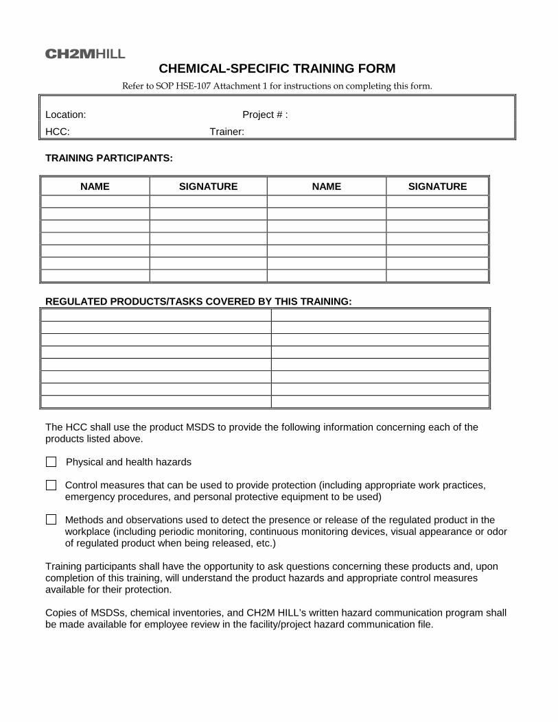
CHEMICAL-SPECIFIC TRAINING FORM
Refer to SOP HSE-107 Attachment 1 for instructions on completing this form. Location: Project # :
HCC: Trainer: TRAINING PARTICIPANTS:
NAME SIGNATURE NAME SIGNATURE REGULATED PRODUCTS/TASKS COVERED BY THIS TRAINING: The HCC shall use the product MSDS to provide the following information concerning each of the products listed above.
Physical and health hazards
Control measures that can be used to provide protection (including appropriate work practices, emergency procedures, and personal protective equipment to be used)
Methods and observations used to detect the presence or release of the regulated product in the
workplace (including periodic monitoring, continuous monitoring devices, visual appearance or odor of regulated product when being released, etc.)
Training participants shall have the opportunity to ask questions concerning these products and, upon completion of this training, will understand the product hazards and appropriate control measures available for their protection. Copies of MSDSs, chemical inventories, and CH2M HILL’s written hazard communication program shall be made available for employee review in the facility/project hazard communication file.

CH2M HILL Health and Safety Plan Attachment 4
Project Activity Self-Assessment Checklists/Permits/Forms Biological Prevention Measures Hazardous Materials Handling Traffic Control

CH2M HILL Health and Safety Plan Attachment 5
Key Target Zero Program Elements Activity Hazard Analysis Pre-Task Safety Plans
Safe Behavior Observation Incident Report and Investigation
(use electronic form when possible) HITS
Lessons Learned Template

Contract Task Order WE-21 MCB CamLej- OU1 and OU2 ACTIVITY HAZARD ANALYSIS – Groundwater Sampling
Task Breakdown Potential Hazards Critical Safety Practices Personal Protective
Clothing and Equipment Groundwater Sampling
Slips, Trips, Falls • Be aware of poor footing, potential slipping/tripping hazards in the work area, such as wet/steep slopes, stumps/roots, unprotected holes, ditches, rip rap, utilities, ground protrusions. Observe and avoid areas of unprotected holes, ramps and ground penetrations or protrusions (stumps, roots, holes curbs, utility structures etc). Use sturdy hard toe work boots with sufficient ankle support.
• Institute and maintain good housekeeping practices.
Standard Level D PPE * * Work clothes, reflective vests/ high visibility clothing, hard hat,
safety glasses and sturdy hard toed work boots, hand and
hearing protection, as dictated by task.
Manual Lifting • CH2M HILL or subcontract personnel must notify supervisors or safety representatives of preexisting medical conditions that may be aggravated or re-injured by lifting activities.
• When lifting objects, lift using knees not back. For repetitive lifting tasks, the use of lifting braces/supports may be considered. If heavy equipment isn’t available to have someone assist with the lift— especially for heavy (> 50lbs.) or awkward loads. Use heavy equipment to transfer heavy or awkward loads wherever possible.
• Plan storage and staging to minimize lifting or carrying distances. Make sure the path of travel is clear prior to the lift.
• Avoid carrying heavy objects above shoulder level.
Standard Level D PPE
Noise • Personnel exposed to loud working environments shall wear hearing protection.
Standard Level D PPE
High Ambient Temperature
• Provide fluids to prevent worker dehydration. • Monitor for heat stress in accordance with HSP (maintain use of buddy system). • Institute a proper work-break regiment to avoid heat stress symptoms and
overexertion.
Standard Level D PPE (light colored clothing)

Contract Task Order WE-21 MCB CamLej- OU1 and OU2 ACTIVITY HAZARD ANALYSIS – Groundwater Sampling
Task Breakdown Potential Hazards Critical Safety Practices Personal Protective
Clothing and Equipment Groundwater Sampling (continued)
Struck/pinched • Wear reflective warning vests or high visibility clothing. • Isolate equipment swing areas from workers, fixed objects or other equipment. • Make/maintain eye contact with operators before approaching equipment. Do
not approach equipment from rear or from blind spot of operator. • Understand and review hand signals. Designate one person to provide hand
signals to equipment operators. • Ensure equipment has operable back-up alarms. • Avoid positioning between fixed objects and operating equipment. • No one shall walk under or in front of suspended loads. Only tagged, load rated
and inspected rigging shall be used to lift loads. Become familiar with vertical, basket and choker load ratings of rigging.
Standard Level D PPE
Biological • Observe ground surfaces especially in wet or grassy areas, tree trunks, and rock piles for evidence and presence of snakes (poisonous).
• Observe ground surfaces or surrounding vegetation or structures for presence fire ants, spiders, bee/wasp hives etc.
• Observe areas for presence of stinging insects. Notify supervisors of known allergies to stinging insects and location of antidotes.
• Use insect repellant. Tape pant legs to boots. Frequently check body and clothing for ticks, chiggers, spiders.
• Avoid exposure to blood borne pathogens
Standard Level D PPE
Electric Hazards • If/when electrical extension cords are required to complete work, extension cords must be:
- Equipped with third-wire grounding. - Covered, elevated, or protected from damage when passing through work
areas. - Protected from pinching if routed through doorways.
- Not fastened with staples, hung from nails, or suspended with wire. - Extension cords and electrical power tools, must have ground fault circuit interrupters
(GFCIs) installed. - Rated to handle the voltage/amperage of equipment.
Standard Level D PPE
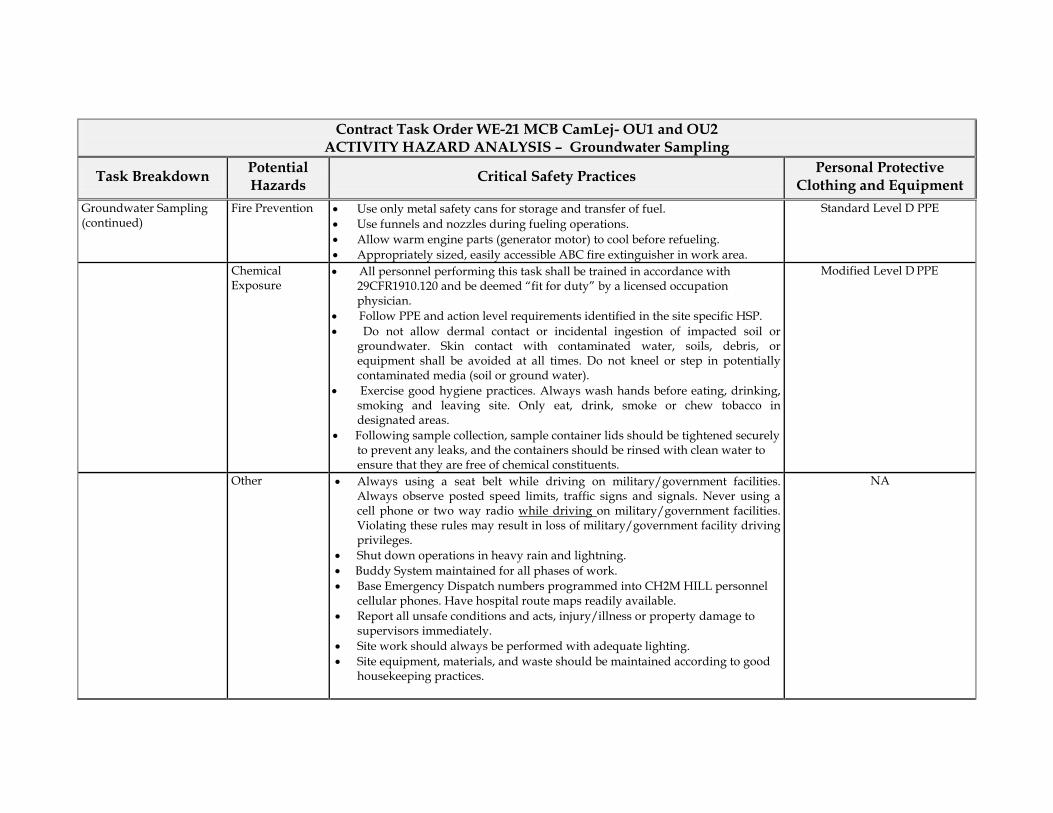
Contract Task Order WE-21 MCB CamLej- OU1 and OU2 ACTIVITY HAZARD ANALYSIS – Groundwater Sampling
Task Breakdown Potential Hazards Critical Safety Practices Personal Protective
Clothing and Equipment Groundwater Sampling (continued)
Fire Prevention • Use only metal safety cans for storage and transfer of fuel. • Use funnels and nozzles during fueling operations. • Allow warm engine parts (generator motor) to cool before refueling. • Appropriately sized, easily accessible ABC fire extinguisher in work area.
Standard Level D PPE
Chemical Exposure
• All personnel performing this task shall be trained in accordance with 29CFR1910.120 and be deemed “fit for duty” by a licensed occupation physician.
• Follow PPE and action level requirements identified in the site specific HSP. • Do not allow dermal contact or incidental ingestion of impacted soil or
groundwater. Skin contact with contaminated water, soils, debris, or equipment shall be avoided at all times. Do not kneel or step in potentially contaminated media (soil or ground water).
• Exercise good hygiene practices. Always wash hands before eating, drinking, smoking and leaving site. Only eat, drink, smoke or chew tobacco in designated areas.
• Following sample collection, sample container lids should be tightened securely to prevent any leaks, and the containers should be rinsed with clean water to ensure that they are free of chemical constituents.
Modified Level D PPE
Other • Always using a seat belt while driving on military/government facilities. Always observe posted speed limits, traffic signs and signals. Never using a cell phone or two way radio while driving
• Shut down operations in heavy rain and lightning.
on military/government facilities. Violating these rules may result in loss of military/government facility driving privileges.
• Buddy System maintained for all phases of work. • Base Emergency Dispatch numbers programmed into CH2M HILL personnel
cellular phones. Have hospital route maps readily available. • Report all unsafe conditions and acts, injury/illness or property damage to
supervisors immediately. • Site work should always be performed with adequate lighting. • Site equipment, materials, and waste should be maintained according to good
housekeeping practices.
NA
ACTIVITY HAZARD ANALYSIS
PRINT NAME
SIGNATURE
Supervisor Name: Date/Time: Safety Officer Name: Date/Time: Employee Name(s): Date/Time: Date/Time: Date/Time: Date/Time: Date/Time: Date/Time: Date/Time: Date/Time: Date/Time:

Pre-Task Safety Plan (PTSP) and Safety Meeting Sign-in Sheet
Project:___________________________ Location: _______________ Date:________________
Supervisor: ________________________________ Job Activity:_______________________________________ _____________________________________________________________________________________________ Attendees: Print Name Sign Name __________________________________________________________________________________________________________________________________________________________________________________________________________________________________________________________________________________________________________________________________________________________________________________________________________________________________________________________________________________________________________________________________________________________________________________________________________________________________________________________________________________ List Tasks and verify that applicable AHAs have been reviewed:
__________________________________________________________________________________________________________________________________________________________________________________________________________________________________________________________________________________________
Tools/Equipment Required for Tasks (ladders, scaffolds, fall protection, cranes/rigging, heavy equipment, power tools):
__________________________________________________________________________________________________________________________________________________________________________________________________________________________________________________________________________________________
Potential H&S Hazards, including chemical, physical, safety, biological and environmental (check all that apply):
__ Chemical burns/contact __ Trench, excavations, cave-ins __ Ergonomics
__ Pressurized lines/equipment __ Overexertion __ Chemical splash
__ Thermal burns __ Pinch points __ Poisonous plants/insects
__ Electrical __ Cuts/abrasions __ Eye hazards/flying projectile
__ Weather conditions __ Spills __ Inhalation hazard
__ Heights/fall > 6 feet __ Overhead Electrical hazards __ Heat/cold stress
__ Noise __ Elevated loads __ Water/drowning hazard
__ Explosion/fire __ Slips, trip and falls __ Heavy equipment
__ Radiation __ Manual lifting __ Aerial lifts/platforms
__ Confined space entry __ Welding/cutting __ Demolition
__Underground Utilities __ Security __ Poor communications Other Potential Hazards (Describe):
_________________________________________________________________________________________________________________________________________________________________________________________________________________________________________________________________________________________

Hazard Control Measures (Check All That Apply): PPE __ Thermal/lined __ Eye __ Dermal/hand __ Hearing __ Respiratory __ Reflective vests __ Flotation device __ Hard Hat
Protective Systems __ Sloping __ Shoring __ Trench box __ Barricades __ Competent person __ Locate buried utilities __ Daily inspections __ Entry Permits/notification
Fire Protection __ Fire extinguishers __ Fire watch __ Non-spark tools __ Grounding/bonding __ Intrinsically safe equipment
Electrical __ Lockout/tagout __ Grounded __ Panels covered __ GFCI/extension cords __ Power tools/cord inspected __ Overhead line clearance __ Underground utils ID’d
Fall Protection __ Harness/lanyards __ Adequate anchorage __ Guardrail system __ Covered opening __ Fixed barricades __ Warning system
Air Monitoring __ PID/FID __ Detector tubes __ Radiation __ Personnel sampling __ LEL/O2 __ No visible dust __ Other
Proper Equipment __ Aerial lift/ladders/scaffolds __ Forklift/heavy equipment __ Backup alarms __ Hand/power tools __ Crane with current inspection __ Proper rigging __ Operator qualified
Welding & Cutting __ Cylinders secured/capped __ Cylinders separated/upright __ Flash-back arrestors __ No cylinders in CSE __ Flame retardant clothing __ Appropriate goggles
Confined Space Entry __ Isolation __ Air monitoring __ Trained personnel __ Permit completed __ Rescue
Medical/ER __ First-aid kit __ Eye wash __ FA-CPR trained personnel __ Route to hospital
Heat/Cold Stress __ Work/rest regime __ Rest area __ Liquids available __ Monitoring __ Training
Vehicle/Traffic __ Traffic control __ Barricades __ Flags __ Signs
Permits __ Hot work __ Confined space __ Lockout/tagout __ Excavation __ Demolition __ Energized work
Demolition __ Pre-demolition survey __ Structure condition __ Isolate area/utilities __ Competent person __ Hazmat present
Inspections: __ Ladders/aerial lifts __ Lanyards/harness __ Scaffolds __ Heavy equipment __ Drill rigs/geoprobe rigs __ Cranes and rigging __ Utilities marked
Training: __ Hazwaste (current) __ Construction __ Competent person __ Task-specific __ FA/CPR __ Confined Space __ Hazcom
Underground Utilities __Dig alert called __3rd Party locater __As-builts reviewed __Interview site staff __Client review __soft locate necessary?
Incident Communications __Work stops until cleared by
TM/CM __Immediate calls to TM/CM __Client notification __24 hour notification setup __Clear communications
AHA’ s __reviewed and approved by HSM __on site and current __applicable for this day’s work __Communication and incident processes included?
Field Notes (including observations from prior day, etc.): ___________________________________________________________________________________________ ______________________________________________________________________________________________________________________________________________________________________________________
Name (Print): _________________________________ Signature:_________________________________ Date:__________________

Safe Behavior Observation Form
Federal or Commercial Sector (check one) Construction or Consulting (check one)
Project Number: Client/Program:
Project Name: Observer: Date: Position/Title of worker observed:
Background Information/ comments:
Task/Observation Observed:
Identify and reinforce safe work practices/behaviors Identify and improve on at-risk practices/acts Identify and improve on practices, conditions, controls, and compliance that eliminate or reduce hazards Proactive PM support facilitates eliminating/reducing hazards (do you have what you need?) Positive, corrective, cooperative, collaborative feedback/recommendations
Actions & Behaviors Safe At-
Risk Observations/Comments
Current & accurate Pre-Task Planning/Briefing (Project safety plan, STAC, AHA, PTSP, tailgate briefing, etc., as needed)
Positive Observations/Safe Work Practices:
Properly trained/qualified/experienced
Tools/equipment available and adequate
Proper use of tools Questionable Activity/Unsafe Condition Observed:
Barricades/work zone control
Housekeeping
Communication
Work Approach/Habits
Attitude
Focus/attentiveness Observer’s Corrective Actions/Comments:
Pace
Uncomfortable/unsafe position
Inconvenient/unsafe location
Position/Line of fire
Apparel (hair, loose clothing, jewelry)
Repetitive motion Observed Worker’s Corrective Actions/Comments:
Other… For ES Federal Sector projects please email completed forms to: CH2M HILL ES FED Safe Behavior Observation For ES Commercial Sector projects please email completed forms to: CH2M HILL ES COM Safe Behavior Observation For CNR ES staff please email completed forms to: [email protected]

HITS – INCIDENT REPORT HARDCOPY (INITIAL ENTRY)
HITS Incident Report Hardcopy (Phase 1 – Initial Entry) Phase 1 – Initial Entry Type of Incident
Injury/Illness (May select more than one)
Property Damage Spill/Release Environment/Permit
Near Miss Other
Preparer’s Name: _____________________________________________ Preparer’s Phone Number: _______________________________ General Information Section
Date of Incident: _________________ Time of Incident: _____________ AM / PM What Business Group is accountable for this incident: _____________________________________________________________________ What Business Group SubGroup is accountable for this incident: ____________________________________________________________ What CH2M HILL Company is accountable for this incident: _________________________________________________________________ Where did the Incident occur? United States, Geographic Region: __________________________________ Canada, Province/Territory: ________________________________________ International, County: _____________________________________________
Company Premises, CH2M HILL Office (use 3 letter office code if available): _______________________________________________ Location of Incident?
Project, Project name: __________________________________________________________________________________________ In Transit Traveling from: _______________________________________________________________________________________________ Traveling to: __________________________________________________________________________________________________ At Home Other, Specify: ________________________________________________________________________________________________ Describe the incident: ________________________________________________________________________________________________ ____________________________________________________________________________________________________________________ ____________________________________________________________________________________________________________________ Describe how this event could have been prevented: _______________________________________________________________________ ____________________________________________________________________________________________________________________ Provide Witness Information: Name: ______________________________________________________ Phone: _______________________________ Name: ______________________________________________________ Phone: _______________________________ Name: _____________________________________________________ Phone: _______________________________ Personnel Notified of Incident (Provide name, date and time): CH2M HILL Personnel: ____________________________________________________________________________________________ Client Personnel: _________________________________________________________________________________________________ Additional Comments: ____________________________________________________________________________________________________________________ ____________________________________________________________________________________________________________________ Injury/Ilness Section Who was injured?
[Complete only if Injury/Illness Incident type selected]
CH2M HILL Employee or CH2M HILL Temp Employee Subcontractor to CH2M HILL (Non-LLC Joint Venture Project) LLC Joint Venture Partner Employee LLC Joint Venture Project Subcontractor/Contractor Other Name of Injured: __________________________________________________ Job Title: _________________________________________ Employer Name: ________________________________________________ Supervisor of Employee: _______________________________
Business Group of Injured Employee: ______________________________________________________________________________ Complete for CH2M HILL Employee Injuries
Has the employee called the Injury Management Administrator (1-800-756-1130)? Yes No Not Sure
Has the injured employee’s supervisor been notified of this incident? Yes No Not Sure

HITS – INCIDENT REPORT HARDCOPY (INTITIAL ENTRY)
Has the project safety coordinator been notified of this incident? Complete for Non-CH2M HILL Employee Injuries
Yes No Not Sure Project Safety Coordinator: _______________________________________________________________________________________
Body Part Affected: ___________________________________________________________________________________________________ Injury/Illness (Result): _________________________________________________________________________________________________ Describe treatment provided (if medication provided, identify whether over-the-counter or prescription): ___________________________ ____________________________________________________________________________________________________________________ Describe any work restriction prescribed (include dates and number of days): _________________________________________________ ____________________________________________________________________________________________________________________ Physician/Health Care Provider Information
Name: ________________________________________________________________________ Phone: _______________________ Was treatment provided away from the worksite?
No Yes
Facility Name: _______________________________________________________________________________________________ Address: ___________________________________________________________________________________________________ City: ____________________________________________________________________ Phone Number: ____________________ Was injured treated in an emergency room?
No Yes Was injured hospitalized overnight as an in-patient?
No Yes
General Information Environmental SectionWho had control of the area during the incident?
[Complete only if Environment/Permit or Spill/Release Incident type selected]
CH2M HILL, Company: _________________________________________________________________________________________ Subcontractor, Company: _______________________________________________________________________________________ Joint Venture Partner/Contractor/Subcontractor, Company: _____________________________________________________________ Other, Company: ______________________________________________________________________________________________ Relationship to CH2M HILL: _____________________________________________________________________________________ Property Damage Section Property Damaged: ____________________________________________________________________________________________________
[Complete only if Property Damage Incident type selected]
Property Owner: _______________________________________________________________________________________________________ Damage Description: ___________________________________________________________________________________________________ Estimated US Dollar Amount: ____________________________________________________________________________________________
Spill or Release Section Substance: ___________________________________________________________________________________________________________
[Complete only if Spill/Release Incident type selected]
Estimated Quantity: ____________________________________________________________________________________________________ Did the spill/release move off the property?: _________________________________________________________________________________ Spill/Release From: ____________________________________________________________________________________________________ Spill/Release To: _____________________________________________________________________________________________________ Environment/Permit Section Describe Environmental or Permit Issue: ___________________________________________________________________________________
[Complete only if Environment/Permit Incident type selected]
Permit Type: _________________________________________________________________________________________________________ Permitted Level or Criteria (e.g., discharge limit): _____________________________________________________________________________ Permit Name and Number (e.g., NPDES No. ST1234): ________________________________________________________________________ Substance and Estimated Quantity: _______________________________________________________________________________________ Duration of Permit Exceedence: __________________________________________________________________________________________

Lessons Learned [Date] ESBG LL-11-xx
Subject [Insert Descriptive Name of Lessons Learned]
CH2M HILL Project? [Yes or No]
Situation [Describe incident or situation that occurred in general terms. Try to be brief and avoid unnecessary details such as names of people or projects, business groups, divisions, dates, location, etc.]
Lessons Learned
(Recommendations and Comments)
• Bullet out any lessons learned, recommendations or other important “take away” information that would benefit others. Tie the recommendations to the incident or event, and avoid including information that is not directly tied to the event.
Submitted By [Name/Office Location/Phone]
Additional Information Contact
[Name/Office Location/Phone]
Keywords/Categories [Insert any keywords or incident categories that would aid in a search for this lessons learned]
Send completed Lessons Learned to the ESBG HSSE Director for posting and distribution. Please include a recommended distribution list.
CH2M HILL Health and Safety Plan Attachment 6
Fact Sheets Tick Fact Sheet
Vehicle Accident Guidance Working Alone

2012 LONG TERM MONITORING PROGRAM HSP_1 18 2012.CLW.DOC
Tick-Borne Pathogens — A Fact Sheet Most of us have heard of Lyme disease or Rocky Mountain Spotted Fever (RMSF), but there are actually six notifiable tick-borne pathogens that present a significant field hazard. In some areas, these account for more than half of our serious field incidents. The following procedures should be applied during any field activity—even in places that are predominantly paved with bordering vegetation.
Hazard Recognition An important step in controlling tick related hazards is understanding how to identify ticks, their habitats, their geographical locations, and signs and symptoms of tick-borne illnesses.
Tick Identification There are five varieties of hard-bodied ticks that have been associated with tick-borne pathogens. These include: • Deer (Black Legged) Tick (eastern and pacific varieties)
• Lone Star Tick
• Dog Tick
• Rocky Mountain Wood Tick These varieties and their geographical locations are illustrated on the following page.
Tick Habitat In eastern states, ticks are associated with deciduous forest and habitat containing leaf litter. Leaf litter provides a moist cover from wind, snow, and other elements. In the north-central states, is generally found in heavily wooded areas often surrounded by broad tracts of land cleared for agriculture. On the Pacific Coast, the bacteria are transmitted to humans by the western black-legged (deer) tick and habitats are more diverse. For this region, ticks have been found in habitats with forest, north coastal scrub, high brush, and open grasslands. Coastal tick populations thrive in areas of high rainfall, but ticks are also found at inland locations.
Illnesses and Signs & Symptoms There are six notifiable tick-borne pathogens that cause human illness in the United States. These pathogens may be transmitted during a tick bite—normally hours after attachment. The illnesses, presented in approximate order of most common to least, include: • Lyme (bacteria)
• RMSF (bacteria)
• Ehrlichiosis (bacteria)
• STARI (Southern Tick-Associated Rash Illness) (bacteria)
• Tularemia (Rabbit Fever) (bacteria)
• Babesia (protozoan parasite) Symptoms will vary based on the illness, and may develop in infected individuals typically between 3 and 30 days after transmission. Some infected individuals will not become ill or may develop only mild symptoms. These illnesses present with some or all of the following signs & symptoms: fever, headache, muscle aches, stiff neck, joint aches, nausea, vomiting, abdominal pain, diarrhea, malaise, weakness, small solid, ring-like, or spotted rashes. The bite site may be red, swollen, or develop ulceration or lesions. For Lyme disease, the bite area will sometimes resemble a target pattern. A variety of long-term symptoms may result if the illness is left untreated, including debilitating effects and death.

2012 LONG TERM MONITORING PROGRAM HSP_1 18 2012.CLW.DOC
Lone Star Tick
Distribution of Lone Star Tick (Green)
Deer Tick
From Left: adult female, adult male, nymph, and larvae Deer Tick (cm scale)
Distribution of Deer Tick (dark green)
Distribution of Pacific Deer Tick (dark green)
Dog Tick
Rocky Mountain Wood Tick

Hazard Control The methods for controlling exposure to ticks include, in order of most- to least-preferred: • Avoiding tick habitats and ceasing operations in heavily infested areas
• Reducing tick abundance through habitat disruption or application of acracide
• Personal protection through use of repellants and protective clothing
• Frequent tick inspections and proper hygiene Vaccinations are not available and preventative antibiotic treatment after a bite is generally not recommended.
Avoidance and Reduction of Ticks To the extent practical, tick habitats should be avoided. In areas with significant tick infestation, consider stopping work and withdrawing from area until adequate tick population control can be achieved. Stopping and withdrawing should be considered as seriously as entering an area without proper energy control or with elevated airborne contaminants—tick-borne pathogens present risk of serious illness! In areas where significant population density or infestation exists, tick reduction should be considered. Tick reduction can be achieved by disrupting tick habitats and/or direct population reduction through the use of tick-toxic pesticides (Damminix, Dursban, Sevin, etc.). Habitat disruption may include only simple vegetative maintenance such as removing leaf litter and trimming grass and brush. Tick populations can be reduced by between 72 and 100 percent when leaf litter alone is removed. In more heavily infested areas, habitat disruption may include grubbing, tree trimming or removal, and pesticide application (Damminix, Dursban, Sevin, etc.). This approach is practical in smaller, localized areas or perimeter areas that require occasional access. Habitat controls are to be implemented with appropriate health and safety controls, in compliance with applicable environmental requirements, and may be best left to the property owner or tenant or to a licensed pesticide vendor. Caution should be exercised when using chemical repellents or pesticides in or around areas where environmental or industrial media samples will be collected for analysis.
Personal Protection After other prevention and controls are implemented, personal protection is still necessary to control exposure to ticks. Personal protection must include all of the following steps: • So that ticks may be easily seen, wear light-colored clothing. Full-body New Tyvek (paper-like
disposable coveralls) may also be used
• To prevent ticks from getting underneath clothing tuck pant legs into socks or tape to boots
• Wear long-sleeved shirts, a hat, and high boots
• Apply DEET repellent to exposed skin or clothing per product label
• Apply permethrin repellent to the outside of boots and clothing before wearing, per product label
• Frequently check for ticks and remove from clothing
• At the end of the day, search your entire body for ticks (particularly groin, armpits, neck, and head) and shower

• To prevent pathogen transmission through mucous membranes or broken/cut skin, wash or disinfect hands and/or wear surgical-style nitrile gloves any time ticks are handled
Pregnant individuals and individuals using prescription medications should consult with their physician and/or pharmacists before using chemical repellents. Because human health effects may not be fully known, use of chemical repellents should be kept to a minimum frequency and quantity. Always follow manufacturers’ use instructions and precautions. Wash hands after handling, applying, or removing protective gear and clothing. Avoid situations such as hand-to-face contact, eating, drinking, and smoking when applying or using repellents. Remove and wash clothes per repellent product label. Chemical repellents should not be used on infants and children. Vaccinations are generally not available for tick-borne pathogens. Although production of the LYMErix™ Lyme disease vaccination has been ceased, vaccination may still be considered under specific circumstances and with concurrence from the consulting physician.
Tick Check A tick check should be performed after field survey before entering the field vehicle (you do not want to infest your field vehicle with ticks). Have your field partner check your back; the backs of your legs, arms, and neck; and your hairline. Shake off clothing as thorough as possible before entering the vehicle. Once the field day is complete, repeat this procedure and perform a thorough self check. If a tick has embedded itself into the skin, remove the tick as described below.
Tick Removal 1. Use the tick removal kit obtained through the CH2M HILL Milwaukee warehouse, or a fine-tipped tweezers or shield your fingers with a tissue, paper towel, or nitrile gloves. Error! Objects cannot be created from editing field codes. 2. Grasp the tick as close to the skin surface as possible and pull upward with steady, even pressure. Do not twist or jerk the tick; this may cause the mouthparts to break off and remain in the skin. If this happens, remove mouthparts with tweezers. Consult your healthcare provider if infection occurs.
3. Avoid squeezing, crushing or puncturing the body of the tick because its fluids (saliva, hemolymph, gut contents) may contain infectious organisms. Releasing these organisms to the outside of the tick’s body or into the bite area may increase the chance of infectious organism transmission. 4. Do not handle the tick with bare hands because infectious agents may enter through mucous membranes or breaks in the skin. This precaution is particularly directed to individuals who remove ticks from domestic animals with unprotected fingers. Children, elderly persons, and immunocompromised persons may be at greater risk of infection and should avoid this procedure. 5. After removing the tick, thoroughly disinfect the bite site and wash your hands with soap and water. 6. Should you wish to save the tick for identification, place it in a plastic bag, with the date of the tick bite, and place in your freezer. It may be used at a later date to assist a physician with making an accurate diagnosis (if you become ill).

Note: Folklore remedies such as petroleum jelly or hot matches do little to encourage a tick to detach from skin. In fact, they may make matters worse by irritating the tick and stimulating it to release additional saliva, increasing the chances of transmitting the pathogen. These methods of tick removal should be avoided. In addition, a number of tick removal devices have been marketed, but none are better than a plain set of fine tipped tweezers.
First-Aid and Medical Treatment
Tick bites should always be treated with first-aid. Clean and wash hands and disinfect the bite site after removing embedded tick. Individuals previously infected with Lyme disease does not confer immunity—re-infection from future tick bites can occur even after a person has contracted a tick-borne disease. The employee should contact the Injury Management/Return To Work provider (IMRTW), WorkCare using the toll-free number 866-893-2514 to report the tick bite. WorkCare will follow-up with each CH2M Hill employee who reports a tick bite and is at risk of developing Lyme disease by monitoring for symptoms up to 45 days, and will refer the employee to a medical provider for evaluation and treatment as necessary.

Vehicle Accident Guidance—ESBG Remember that if you a renting a non-CH2M HILL owned vehicle (short-term rental) in the U.S., you should carry the insurance card from the state where your driver’s license is issued.
If you operate a fleet vehicle, carry the insurance card where the vehicle is registered.
Please see link below to print out an insurance card (for CH2M HILL employees only). The page shows state-specific restrictions and the definitions of hired, owned, etc., vehicles.
https://communities.int.ch2m.com/legal/insurance/Shared%20Documents/AutoID_Cards.aspx?PageView=Shared
1. If you are injured, call 911 for emergency medical treatment or 1-866-893-2514 to contact the CH2M HILL Occupational Nurse/Physician for minor injuries. If you feel you have not been injured, contact the RHSM for guidance on whether calling the CH2M HILL Occupation Nurse/Physician is applicable.
For ALL Vehicles if you are in an accident:
2. Call the Police--For any vehicle accident/damage, it is recommended that the local police (or site security/emergency services if working on a client site that provides such services) be called to determine if a report needs to be filed. In some instances, a report may not be required (during accident alerts, or in public parking lots). Document that the authorities were called and follow up with any guidance they give you. State requirements vary. If a report is filed, obtain a copy.
3. Notify Supervisor, (and PM/RHSM if working on a project site)
4. Complete a HITS report on the VO.
Definition: These are vehicles rented for greater than 90 days or rentals that are leased (either through ARI [Automotive Rental, Inc.] or leases from other companies [older fleet vehicles]).
Additional Steps for FLEET VEHICLES:
Report the accident to the following:
1. Fill out and Auto Loss Notice on the Virtual Office (click “Company Resources,” then “Corporate Groups,” then “Insurance”). See screen shot below.

2. Contact Zurich (1-877-246-3478 or 1-800-987-3373).
3. Contact Linda George/DEN at 720-286-2057.
Note: If you are an ES employee that happens to use an OMI vehicle on a project and get into an accident, you must also contact Michelle Garlington/DEN (720-286-4273).
1. Fill out and Auto Loss Notice on the Virtual Office (click “Company Resources,” then “Corporate Groups,” then “Insurance”). See screen shot above.
Additional Steps for RENTALS:
2. Call 1-800-VISA-911 (only if the car has been rented for less than 31 days—they provide some additional physical damage coverage in this time period).
3. Call Zurich (1-877-246-3478 or 1-800-987-3373).
4. Call the rental company (Budget, National, Enterprise, etc.).
5. Call Jennifer Rindahl/DEN at 720-286-2449.
For Personally Owned Vehicles (POVs):
CH2M HILL does not provide auto insurance for POVs, it is responsibility of the owner. If you are in a vehicle accident conducting company business, contact the police as above, supervisor, and 911 or CH2M HILL’s occupational nurse/physician as stated above. Complete a HITS report. Refer to the Employee Handbook/Policies, assistance for meeting personal insurance deductibles (up to $500) is available with proof of insurance and deductible.
If using your POV for extended project use, notify the PM to make sure a rental car is not needed. Check your insurance policy for guidance on using the POV for business use.
Additional Resources:
Click on form, it will be submitted electronically.

Business Auto Insurance Manual https://www.int.ch2m.com/webuploads/newsgenerator/travel/news/business_auto_manual[1].pdf Claims Resource Manual https://www.int.ch2m.com/intrnl/voffice/corp/insurance/InsHome.asp

WORKING ALONE PROTOCOL CALL – IN CONTACT FORM
Date of site work:_______________ Expected start time:______________ Name of CH2M HILL employee in the field:_____________________________________ Name of CH2M HILL employee responsible to receive contact: Client Emergency Contact (if any): CH2M HILL employee’s contact numbers:
Radio #__________________________ Cell Phone #______________________
Address and Location of work:________________________________________________ Directions/Map: Planned Activity:____________________________________________________________ Specified Frequency and time for call in:________________________________________
Time Verified Location
If lone worker fails to call in at specified frequency/time:
1) Call worker’s radio and cell to determine if an emergency exists. 2) If no reply, immediately call Client security/emergency service if there is one at
the site. 3) If there is no client security call Emergency Services (911). Inform the dispatcher
there is a lone worker that cannot be contacted and there may be an emergency on site. Provide the lone worker’s name, their last known location, and your contact information.
4) After Emergency Services have been contacted, call the other emergency contacts, Project Manager, and Responsible Health and Safety Manager.

Lone work is acceptable with appropriate accountability system in place.
No
Is work outside of normal business hours or daylight hours?
Are there hazards in location or area? (e.g. steep terrain, homeless people, bad neighborhood, weather conditions)
Is high to moderate risk involved in the work?
Is staff inexperienced and/or uncomfortable working alone?
No No
Yes Yes Yes Yes
No
Will employee become fatigued during work activity?
Lone worker mitigation plan required as approved by PM and RHSM (see examples below): - Man-down sensors with automatic notification
- Tight check-in schedule with PM/SC/EMS
No
Yes
Will work be completed in
remote locations?
Yes
Are other Staff on site aware of presence of lone worker and able to maintain communication between staff??
Will field work be completed by lone CH2M HILL worker?
Yes
No
Not a lone worker and no further action required
No
Yes
No
Lone Worker Protocol
CH2M HILL HEALTH AND SAFETY PLAN Attachment 7
Observed Hazard Form

OBSERVED HAZARD FORM
Date reported:_________________ Time reported:___________________
Contractor/s performing unsafe act or creating unsafe condition: 1. _________________________________________________________________________ 2. _________________________________________________________________________ 3. _________________________________________________________________________
Unsafe Act or Condition: __________________________________________________________________________________________________________________________________________________________________________________________________________________________________________________________________________________________________________________________________________________________________________________________________________________________________________________________________________________________________________________________________________________________________________________________________________________________________________________________________________________________________ Location of Unsafe Act or Condition:
Corrective Actions Taken: Date: ___________ ________________________________________________________________________________________________________________________________________________________________________________________________________________________________________________________________________________________________________________________________________
Project Safety Committee Evaluation: Date: ___________ ____________________________________________________________________________________________________________________________________________________________________________________________________________________________________________________________________________________________________________
Name/Company of Observer (optional):
Name of CH2M HILL Representative: ___________________________________________________________________________

CH2M HILL HEALTH AND SAFETY PLAN Attachment 8
Stop Work Order Form

Stop Work Order REPORT PREPARED BY:
Name: Title: Signature: Date:
ISSUE OF NONPERFORMANCE:
Description: Date of Nonperformance: ________________
SUBCONTRACTOR SIGNATURE OF NOTIFICATION:
Name: Title: Signature: Date:
* Corrective action is to be taken immediately. Note below the action taken, sign and return to CCI.* Work may not resume until authorization is granted by CH2M HILL Constructors, Inc. Representative, SUBCONTRACTOR’S CORRECTIVE ACTION
Description: Date of Nonperformance: ________________
SUBCONTRACTOR SIGNATURE OF CORRECTION
Name: Title: Signature: Date:

CH2M HILL HEALTH AND SAFETY PLAN Attachment 9
Agency Inspection Target Zero Bulletin

Environmental Services Business Group
TARGET ZERO Bulletin Subject: HSSE Agency Inspections (OSHA, EPA, DOT, State Health Department)
Do you know what YOU would do if an agency inspector arrived at your site unannounced?
Recently, a State Occupational Safety and Health Administration (OSHA) inspector made an unannounced visit to one of our Federal project sites. OSHA, U.S. Environmental Protection Agency (EPA), and authorized state or local agencies have authority to inspect any facility that is subject to health, safety, and environmental legislation. Inspections may be announced or unannounced. This particular inspector indicated that the project was targeted for an inspection because the work was funded by the American Recovery and Reinvestment Act (ARRA). Enterprise Standard Operating Procedure (SOP) HSE-201, Agency Inspections and Communications, describes the responsibilities, procedures, and requirements associated with inspections conducted by external regulatory agencies, as well as the methods for communicating information to key individuals. This Target Zero Bulletin is a brief summary of what to do in the event of an agency inspection at your site. Refer to the SOP for more specific guidance.
• If the inspection is an Notification of Inspections
announced
• If an
regulatory agency inspection, the Project Manager (PM) should notify the Responsible Health and Safety Manager (RHSM) and Responsible Environmental Manager (REM) well in advance of the inspection.
unannounced
• The ERC must immediately notify the RHSM/REM, as appropriate, of unannounced inspections, or designate someone to call the RHSM/REM. The RHSM/REMs can provide guidance to the field staff and PM.
agency inspector visits one of our projects, Field personnel must immediately notify the project Emergency Response Coordinator (ERC). Typically the ERC is the Safety Coordinator (SC).
• Upon arrival, the ERC must request the inspector to provide official credentials. Record the inspector’s name and office phone number or obtain the inspector’s business card.
Inspector Credential Verification
• The inspector shall sign the visitors log and be given a site-specific health, safety, and environmental protection briefing.
• The inspector shall meet any site access requirements associated with security clearances, specialized training, and medical monitoring. The CH2M HILL representative shall verify that the inspector possesses these requirements; access will only be granted to those areas where appropriate access requirements are met. Some inspectors have the authority to gain access to any work area at any time, such as an inspector with a search warrant. In these cases, we can stop work operations as necessary to protect the safety of the inspector(s).
• The CH2M HILL Project Manager, ERC, RHSM, or REM, and the inspector shall determine attendees for the opening conference. The RHSM (for OSHA and other worker health and safety inspections) or REM (for environmental inspections) shall join the opening conference via conference call.
Opening Conference
• The inspector shall inform CH2M HILL of the purpose of the inspection and provide a copy of the complaint, if applicable.
• The inspector shall outline the scope of the inspection, including employee interviews conducted in private, physical inspection of the workplace and records, possible referrals, discrimination complaints, and the closing conference(s).
• An OSHA inspector may request to review the project OSHA Injury/Illness log, better known as the OSHA 300 Log. Contact your RHSM for assistance in obtaining the OSHA 300 Log.
Requests for OSHA Logs

• Field projects with a continuous duration of one year or longer are considered to be separate establishments and are required to maintain an OSHA 300 log specific to the project. The project OSHA 300 log should be maintained onsite and kept current.
• Recordable injuries and illnesses sustained on field projects less than one year in duration are maintained on the CH2M HILL office log where the injured employee is based.
• The scope of the inspection shall be limited to that indicated by the inspector in the opening conference. The inspector shall be escorted to relevant areas only. The ERC or other designated by the RHSM or REM must accompany the inspector during the inspection.
The Inspection
• Ensure that the inspection is limited to the scope that the inspector disclosed during the opening conference. The ERC should always take notes which identify: areas inspected, machinery or equipment and materials examined, employees or other persons interviewed, and photographs taken by the inspector.
• The inspector will observe safety, health, and environmental conditions and practices and document the inspection process. The inspector may also take photos and instrument readings, examine records, collect air samples, measure noise levels, survey existing engineering controls, and monitor employee exposure to toxic vapors, gases, and dusts.
• CH2M HILL should gather duplicate information (photographs, readings, samples) in the same manner and condition as the inspector. If the equipment needed to take duplicate samples is not onsite, ask the inspector if the sampling can wait until the equipment is available. If samples are taken, request a description of the tests that the agency intends to perform on the samples and request results as soon as they are available.
• Employees may be questioned during the inspection tour. The employee can refuse to speak to an inspector, can speak to the inspector with a company representative (including management) present, or can speak to the inspector privately. It is CH2M HILL policy that employees who wish to speak to the inspector are not discriminated against, intimidated, or otherwise mistreated for exercising their rights during compliance inspections.
• Copies of documents should not be provided to the inspector without the approval of the RHSM or REM or Legal Insurance Department (LID). DO NOT voluntarily release documents. Respond only to inspection team requests.
• During the course of the inspection, the inspector may point out violations. For each violation, the CH2M HILL representative should ask the inspector to discuss possible corrective action. Where possible, violations detected by the inspector should be corrected immediately and noted by the inspector as corrected.
• For those items which cannot be corrected immediately, an action plan shall be formulated for timely correction. In any instance, employees exposed to hazards shall be removed from the area.
After the inspection, a closing conference is normally held as follows: Closing Conference
• The CH2M HILL PM, ERC, RHSM or REM shall be involved via conference call in the closing conference, at a minimum;
• The inspector shall describe the apparent violations found during the inspection and other pertinent issues as deemed necessary by the inspector. CH2M HILL shall be advised of their rights to participate in any subsequent conferences, meetings or discussions. Any unusual circumstances noted during the closing conference shall be documented by the ERC;
• The inspector shall discuss violations observed during the inspection and indicate for which violations a citation and a proposed penalty may be issued or recommended;
• The ERC shall request receipts for all samples and approved documents photocopied by the inspector, request a photocopy of the inspector’s photograph log, and request a copy of the final inspection report; and
• Any documentation from an agency inspection must be transmitted immediately to the RHSM or REM, and LID.
Unannounced regulatory agency inspections may happen at any time on our projects -
Get your RHSM/REM and PM involved immediately if an Inspector arrives.
CH2M HILL HEALTH AND SAFETY PLAN Attachment 10
Completed CH2M HILL AHAs

CH2M HILL HEALTH AND SAFETY PLAN Attachment 11
Material Safety Data Sheets &
Hazard Fact Sheets

Attachment 2 Standard Operating Procedures – CH2MHILL

Field Books QC and Reviewed 05/2011 1
Preparing Field Log Books STANDARD OPERATING PROCEDURE
I. Purpose This SOP provides general guidelines for entering field data into log books during site investigation and remediation activities.
II. Scope This is a general description of data requirements and format for field log books. Log books are needed to properly document all field activities in support of data evaluation and possible legal activities.
III. Equipment and Materials • Log book
• Indelible pen
IV. Procedures and Guidelines Properly completed field log books are a requirement for much of the work we perform under the Navy CLEAN contract. Log books are legal documents and, as such, must be prepared following specific procedures and must contain required information to ensure their integrity and legitimacy. This SOP describes the basic requirements for field log book entries.
A. PROCEDURES FOR COMPLETING FIELD LOG BOOKS
1. Field notes commonly are kept in bound, hard-cover logbooks used by surveyors and produced, for example, by Peninsular Publishing Company and Sesco, Inc. Pages should be water-resistant and notes should be taken only with water-proof, non-erasable permanent ink, such as that provided in Sanford Sharpie permanent markers.
2. On the inside cover of the log book the following information should be included:
• Company name and address
• Log-holders name if log book was assigned specifically to that person
• Activity or location

Field Books QC and Reviewed 05/2011 2
• Project name
• Project manager’s name
• Phone numbers of the company, supervisors, emergency response, etc.
3. All lines of all pages should be used to prevent later additions of text, which could later be questioned. Any line not used should be marked through with a line and initialed and dated. Any pages not used should be marked through with a line, the author’s initials, the date, and the note “Intentionally Left Blank.”
4. If errors are made in the log book, cross a single line through the error and enter the correct information. All corrections shall be initialed and dated by the personnel performing the correction. If possible, all corrections should be made by the individual who made the error.
5. Daily entries will be made chronologically.
6. Information will be recorded directly in the field log book during the work activity. Information will not be written on a separate sheet and then later transcribed into the log book.
7. Each page of the log book will have the date of the work and the note takers initials.
8. The final page of each day’s notes will include the note-takers signature as well as the date.
9. Only information relevant to the subject project will be added to the log book.
10. The field notes will be copied and the copies sent to the Project Manager or designee in a timely manner (at least by the end of each week of work being performed).
B. INFORMATION TO BE INCLUDED IN FIELD LOG BOOKS
1. Entries into the log book should be as detailed and descriptive as possible so that a particular situation can be recalled without reliance on the collector’s memory. Entries must be legible and complete.
2. General project information will be recorded at the beginning of each field project. This will include the project title, the project number, and project staff.
3. Scope: Describe the general scope of work to be performed each day.
4. Weather: Record the weather conditions and any significant changes in the weather during the day.
5. Tail Gate Safety Meetings: Record time and location of meeting, who was present, topics discussed, issues/problems/concerns identified,

Field Books QC and Reviewed 05/2011 3
and corrective actions or adjustments made to address concerns/ problems, and other pertinent information.
6. Standard Health and Safety Procedures: Record level of personal protection being used (e.g., level D PPE), record air monitoring data on a regular basis and note where data were recording (e.g., reading in borehole, reading in breathing zone, etc). Also record other required health and safety procedures as specified in the project specific health and safety plan.
7. Instrument Calibration; Record calibration information for each piece of health and safety and field equipment.
8. Personnel: Record names of all personnel present during field activities and list their roles and their affiliation. Record when personnel and visitors enter and leave a project site and their level of personal protection.
9. Communications: Record communications with project manager, subcontractors, regulators, facility personnel, and others that impact performance of the project.
10. Time: Keep a running time log explaining field activities as they occur chronologically throughout the day.
11. Deviations from the Work Plan: Record any deviations from the work plan and document why these were required and any communications authorizing these deviations.
12. Heath and Safety Incidents: Record any health and safety incidents and immediately report any incidents to the Project Manager.
13. Subcontractor Information: Record name of company, record names and roles of subcontractor personnel, list type of equipment being used and general scope of work. List times of starting and stopping work and quantities of consumable equipment used if it is to be billed to the project.
14. Problems and Corrective Actions: Clearly describe any problems encountered during the field work and the corrective actions taken to address these problems.
15. Technical and Project Information: Describe the details of the work being performed. The technical information recorded will vary significantly between projects. The project work plan will describe the specific activities to be performed and may also list requirements for note taking. Discuss note-taking expectations with the Project Manager prior to beginning the field work.
16. Any conditions that might adversely affect the work or any data obtained (e.g., nearby construction that might have introduced excessive amounts of dust into the air).

Field Books QC and Reviewed 05/2011 4
17. Sampling Information; Specific information that will be relevant to most sampling jobs includes the following:
• Description of the general sampling area – site name, buildings and streets in the area, etc.
• Station/Location identifier • Description of the sample location – estimate location in
comparison to two fixed points – draw a diagram in the field log book indicating sample location relative to these fixed points – include distances in feet.
• Sample matrix and type • Sample date and time • Sample identifier • Draw a box around the sample ID so that it stands out in the
field notes • Information on how the sample was collected – distinguish
between “grab,” “composite,” and “discrete” samples • Number and type of sample containers collected • Record of any field measurements taken (i.e. pH, turbidity,
dissolved oxygen, and temperature, and conductivity) • Parameters to be analyzed for, if appropriate • Descriptions of soil samples and drilling cuttings can be
entered in depth sequence, along with PID readings and other observations. Include any unusual appearances of the samples.
C. SUGGESTED FORMAT FOR RECORDING FIELD DATA
1. Use the left side border to record times and the remainder of the page to record information (see attached example).
2. Use tables to record sampling information and field data from multiple samples.
3. Sketch sampling locations and other pertinent information.
4. Sketch well construction diagrams.
V. Attachments Example field notes.

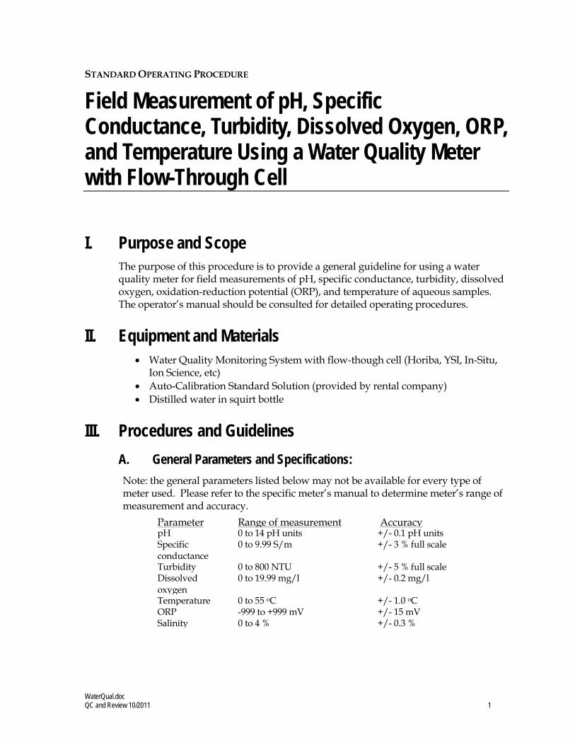
WaterQual.doc QC and Review 10/2011 1
STANDARD OPERATING PROCEDURE
Field Measurement of pH, Specific Conductance, Turbidity, Dissolved Oxygen, ORP, and Temperature Using a Water Quality Meter with Flow-Through Cell
I. Purpose and Scope The purpose of this procedure is to provide a general guideline for using a water quality meter for field measurements of pH, specific conductance, turbidity, dissolved oxygen, oxidation-reduction potential (ORP), and temperature of aqueous samples. The operator’s manual should be consulted for detailed operating procedures.
II. Equipment and Materials • Water Quality Monitoring System with flow-though cell (Horiba, YSI, In-Situ,
Ion Science, etc) • Auto-Calibration Standard Solution (provided by rental company) • Distilled water in squirt bottle
III. Procedures and Guidelines A. General Parameters and Specifications: Note: the general parameters listed below may not be available for every type of meter used. Please refer to the specific meter’s manual to determine meter’s range of measurement and accuracy.
Parameter
Range of measurement
Accuracy
pH
0 to 14 pH units +/- 0.1 pH units Specific conductance
0 to 9.99 S/m
+/- 3 % full scale
Turbidity
0 to 800 NTU
+/- 5 % full scale
Dissolved oxygen
0 to 19.99 mg/l
+/- 0.2 mg/l
Temperature
0 to 55 oC
+/- 1.0 oC
ORP -999 to +999 mV +/- 15 mV Salinity
0 to 4 %
+/- 0.3 %

WaterQual.doc QC and Review 10/2011 2
B. Calibration: Prior to each day’s use, clean the probe and flow-through cell using deionized water and calibrate using the Standard Solution. Refer to the specific instrumentation manual for the proper calibration methods.
C. Sample Measurement: The water quality probes are inserted into a flow-through cell. The purged groundwater is directed through the cell by connecting the pump discharge tubing to the bottom port on the flow through cell, allowing measurements to be collected before the water contacts the atmosphere. As water passes through the flow-through the flow cell, press MEAS to obtain readings or the readings are displayed on the meter for each parameter (dependent on the type of meter used). Record the water quality parameter data in a field notebook. Once the parameters have stabilized (see Low-Flow Groundwater Sampling from Monitoring Wells – EPA Region I and III or Low-Flow Groundwater Sampling from Monitoring Wells – EPA Region IV depending on project site location), remove the tubing from the bottom port of the flow-through cell. Never collect a groundwater sample for laboratory analysis from the flow-through cell. Rinse the flow-though cell between wells to remove any sediment buildup within the cell.
lV. Key Checks and Preventive Maintenance • Calibrate meter • Clean probe with deionized water when done • Refer to operations manual for recommended maintenance and
troubleshooting • Check batteries, and have a replacement set on hand
• Due to the importance of obtaining these parameters, the field team should have a spare unit readily available in case of an equipment malfunction.

LowFlow – EPA Reg IV Created 10/2011 1
STANDARD OPERATING PROCEDURE
Low-Flow Groundwater Sampling from Monitoring Wells – EPA Region IV
I. Purpose and Scope This SOP presents general guidelines for the collection of groundwater samples from monitoring wells using low-flow purging and sampling procedures. Operations manuals should be consulted for specific calibration and operating procedures.
II. Equipment and Materials • Adjustable-rate positive-displacement pump, submersible pump, or peristaltic
pump • Horiba®
• Flow-through cell with inlet/outlet ports for purged groundwater and watertight ports for each probe
U-22 or equivalent water quality meters to monitor pH, specific conductance, turbidity, dissolved oxygen, oxidation-reduction potential (ORP), and temperature
• Generator or alternate power source depending on pump type • Water-level indicator • Disposable Teflon, Teflon-lined polyethylene tubing or polyethylene tubing for
metals and other inorganics • Plastic sheeting • Well-construction information • Calibrated container and stopwatch to determine flow rate • Sample containers • In-line disposable 0.45µm filters (QED®
• Shipping supplies (labels, coolers, and ice) FF8100 or equivalent)
• Field book
III. Procedures and Guidelines A. Setup and Purging
1. Obtain information on well location, diameter(s), depth, and screen interval(s), and the method for disposal of purged water.
2. Calibrate instruments according to manufacturer's instructions.
3. The well number, site, date, and condition are recorded in the field logbook.

LowFlow – EPA Reg IV Created 10/2011 2
4. Plastic sheeting is placed on the ground, and the well is unlocked and opened. All decontaminated equipment to be used in sampling will be placed only on the plastic sheeting until after the sampling has been completed. To avoid cross-contamination, do not let any downhole equipment touch the ground.
5. All sampling equipment and any other equipment to be placed in the well is cleaned and decontaminated before sampling in accordance with SOP Decontamination of Personnel and Equipment.
6. Water level measurements are collected in accordance with the Water Level Measurements SOP. Do not measure the depth to the bottom of the well at this time; this reduces the possibility that any accumulated sediment in the well will be disturbed. Obtain depth to bottom information from well construction log.
7. Attach and secure the tubing to the low-flow pump. Lower the pump slowly into the well and set it at approximately the middle of the screen. Place the pump intake in the middle of the saturated screen length and should be at least two feet above the bottom of the well to avoid mobilization of any sediment present in the bottom.
8. Insert the measurement probes into the flow-through cell. The purged groundwater is directed through the cell, allowing measurements to be collected before the water contacts the atmosphere.
9. If using a generator, locate it 30 feet downwind from the well to avoid exhaust fumes contaminating the samples.
10. Start purging the well at 0.2 to 0.5 liters per minute. Avoid surging. Purging rates for more transmissive formations could be started at 0.5-liter to 1 liter per minute. The initial field parameters of pH, specific conductance, dissolved oxygen, ORP, turbidity, and temperature of water are measured and recorded in the field logbook.
11. The water level should be monitored during purging, and, ideally, the purge rate should equal the well recharge rate so that there is little or no drawdown in the well (i.e., less than 0.3-foot). The water level should stabilize for the specific purge rate. Record adjustments in the purge rate and changes in depth to water in the logbook. Purge rates should, if needed, be decreased to the minimum capabilities of the pump (0.1- to 0.2-liter per minute) to avoid affecting well drawdown. If the water level is drawn down by more than 0.3 feet, purging should be conducted in accordance with SOP Groundwater Sampling from Monitoring Wells
12. During purging, the field parameters are measured frequently (every 5 minutes) until the parameters have stabilized. Field parameters are considered stable when measurements meet the following criteria:
.
• pH: within 0.1 pH units

LowFlow – EPA Reg IV Created 10/2011 3
• Specific conductance: within 10 percent
• Turbidity: <10 NTU or within 10 percent
• Temperature: constant
B. Sample Collection
Once purging is complete the well is ready to sample. The elapsed time between completion of purging and collection of the groundwater sample should be minimized. Typically, the sample is collected immediately after the well has been purged, but this is also dependent on well recovery.
Samples will be placed in sample containers that have been cleaned to laboratory standards and are preserved in accordance with the analytical method. The containers are typically pre-preserved, if required.
VOC samples are normally collected first and directly into pre-preserved sample containers (see Special Conditions for Sampling with Peristaltic Pumps).
The steps to be followed for sample collection are as follows:
1. The cap is removed from the sample bottle, and the bottle is tilted slightly.
2. The sample is slowly poured from the bailer or discharged from the pump so that it runs down the inside of the sample bottle with a minimum of splashing. The pumping rate should be reduced to approximately 100 ml per minute when sampling VOCs.
3. Inorganics, including metals, may be collected and preserved in the filtered form as well as the unfiltered form. Disposable in-line filters (0.45 micron filter), connected to the end of the sample tubing,, are typically used for field filtration. Samples are field filtered as the water is being placed into the sample container. If a bailer is used, filtration may be driven by a peristaltic pump.
4. Adequate space is left in the bottle to allow for expansion, except for VOC vials, which are filled to the top with a positive meniscus.
5. The bottle is capped and clearly labeled.
6. Samples are placed in appropriate containers and, if necessary, packed with ice in coolers as soon as practical.
7. Nondedicated equipment is cleaned and decontaminated in accordance with the Decontamination of Personnel and Equipment SOP.
The following information, at a minimum, will be recorded in the log book:
1. Sample identification (site name, location, and project number; sample name/number and location; sample type and matrix; time and date; sampler's identity)

LowFlow – EPA Reg IV Created 10/2011 4
2. Sample source and source description
3. Field observations and measurements (appearance, volatile screening, field chemistry, sampling method), volume of water purged prior to sampling, number of well volumes purged, and field parameter measurements
4. Sample disposition (preservative; laboratory name, date and time sent; laboratory sample number, chain-of-custody number, sample bottle lot number)
5. Additional remarks
Special Conditions for Sampling with Peristaltic Pumps It is not acceptable to collect samples for organic compounds analyses through the flexible tubing used in the pump head. When collecting samples for organic compound analyses it is necessary to use a vacuum container, placed between the pump and the well for sample collection.
The following step-by-step procedures describe the process of sampling with a peristaltic pump and vacuum jug (see note following these procedures for collection of VOC samples):
1. Disconnect the purge tubing from the pump. Make sure the tubing is securely attached to the protective casing or other secure object.
2. Insert the tubing into one of the ferrule nut fittings of a Teflon® vacuum container transfer cap assembly.
3. Place a suitable length of Teflon® tubing between the remaining transfer cap assembly ferrule nut fitting and the vacuum side of the flexible tubing in the peristaltic pump head. Securely hand-tighten both fittings.
4. Turn the pump on. Water should begin to collect in the transfer container (typically a 1-liter “Boston round” glass sample container) within a few minutes. If water does not begin to flow into the container within several minutes, check the transfer cap fittings and make sure the assembly is tightly attached to the container. It may be necessary to tighten the ferrule nuts with a wrench or pliers to achieve a vacuum in the system, particularly when approaching the maximum head difference between the pump and water table (limit of suction).
5. When the transfer container is nearly full, turn off the pump, remove the transfer cap assembly, and pour the sample into the appropriate containers.
6. If additional sample volume is needed, replace the transfer cap assembly, turn the pump on, and collect additional volume.
NOTE: Samples for volatile organic compound analyses cannot be collected using the vacuum jug method. If samples for VOC analyses are required,

LowFlow – EPA Reg IV Created 10/2011 5
they must be collected with a bailer or by other approved methods, such as the “soda straw” method. The “soda straw” method involves allowing the tubing to fill, by either lowering it into the water column (A) or by filling it via suction applied by the pump head (B). If method (A) is used, the tubing is removed from the well after filling and the captured sample is allowed to drain into the sample vial. If method (B) is used, after running the pump and filling the tubing with sample, the pump speed is reduced and the direction reversed to push the sample out of the tubing into the vials. Avoid completely emptying the tubing when filling the sample vials when using method (B) to prevent introducing water that was in contact with the flexible pump head tubing. Either method is repeated, as necessary, until all vials are filled. Samples for some constituents, primarily inorganic analytes such as metals and cyanide, may be collected directly from the peristaltic pump head tubing. This method is acceptable under the following conditions:
• The pump head tubing must be changed between sampling
locations;
• An equipment rinsate blank must be collected by pumping de-ionized water through a piece of the tubing.
C. Additional remarks
1. If the well goes dry during purging, wait until it recovers sufficiently to remove the required volumes to sample all parameters. It may be necessary to return periodically to the well but a particular sample (e.g., large amber bottles for semivolatile analysis) should be filled at one time rather than over the course of two or more visits to the well.
2. Disposable tubing is disposed of with PPE and other site trash.
IV. Attachments White paper on reasons and rationale for low-flow sampling.
V. Key Checks and Preventative Maintenance • The drawdown in the well should be minimized as much as possible
(preferably no more than 0.5-foot to 1 foot) so that natural groundwater-flow conditions are maintained as closely as possible.
• The highest purging rate should not exceed 1 liter per minute. This is to keep the drawdown minimized.

LowFlow – EPA Reg IV Created 10/2011 6
• Stirring up of sediment in the well should be avoided so that turbidity containing adsorbed chemicals is not suspended in the well and taken in by the pump.
• Overheating of the pump should be avoided to minimize the potential for losing VOCs through volatilization.
• Keep the working space clean with plastic sheeting and good housekeeping.
• Maintain field equipment in accordance with the manufacturer’s recommendations. This will include, but is not limited to:
• Inspect sampling pump regularly and replace as warranted
• Inspect quick-connects regularly and replace as warranted
• Verify battery charge, calibration, and proper working order of field measurement equipment prior to initial mobilization and daily during field efforts

LowFlow – EPA Reg IV Created 10/2011 7
Attachment to the SOP on Low-Flow Sampling Groundwater Sampling from Monitoring Wells
White Paper on Low-Flow Sampling
EPA recommends low-flow sampling as a means of collecting groundwater samples in a way that minimizes the disturbance to the natural groundwater flow system and minimizes the introduction of contamination into the samples from extraneous sources. The following are details about these issues.
When a pump removes groundwater from the well at the same rate that groundwater enters the well through the screen, the natural groundwater-flow system around the well experiences a minimum of disturbance. Some disturbance is bound to occur because you are causing groundwater to flow to the well in a radial fashion that otherwise would have flowed past it. However, the resulting low-flow sample provides the most-representative indication we can get of groundwater quality in the immediate vicinity of the well.
Normally, when a well is pumped at an excessive rate that drops the water level in the well below the water level in the aquifer, the water cascades down the inside of the well screen when it enters the well. The turbulence from this cascading causes gases such as oxygen and carbon dioxide to mix with the water in concentrations that are not representative of the native groundwater and are higher than expected. This causes geochemical changes in the nature of the water that can change the concentrations of some analytes, particularly metals, in the groundwater sample, not mention it’s effect on the dissolved oxygen levels that then will be measured in the flow-through cell. Such turbulence also may cause lower-than-expected concentrations of volatile organic compounds due to volatilization.
For wells in which the water level is above the top of the screen, the water up in the riser is out of the natural circulation of the groundwater and, therefore, can become stagnant. This stagnant water is no longer representative of natural groundwater quality because its pH, dissolved-oxygen content, and other geochemical characteristics change as it contacts the air in the riser. If we minimize the drawdown in the well when we pump, then we minimize the amount of this stagnant water that is brought down into the well screen and potentially into the pump. As a result, a more-representative sample is obtained.
Typically, wells contain some sediment in the bottom of the well, either as a residue from development that has settled out of the water column or that has sifted through the sand pack and screen since the well was installed. This sediment commonly has adsorbed on it such analytes as metals, SVOCs, and dioxins that normally would not be dissolved in the groundwater. If these sediments are picked up in the groundwater when the well is disturbed by excessive pumping, they can:
• Make filtering the samples for metals analysis more difficult
• Add unreasonably to the measured concentration of SVOCs and other organic compounds
The SOP for low-flow sampling has been modified recently and should be consulted for additional information about low-flow sampling and ways of dealing with wells in which the water level cannot be maintained at a constant level.

Decon.doc QC and revised 5/2011 1
STANDARD OPERATING PROCEDURE
Decontamination of Personnel and Equipment
I. Purpose To provide general guidelines for the decontamination of personnel, sampling equipment, and monitoring equipment used in potentially contaminated environments.
II. Scope This is a general description of decontamination procedures.
III. Equipment and Materials • Demonstrated analyte-free, deionized (“DI”) water (specifically, ASTM Type
II water or lab-grade DI water)
• Potable water; must be from a municipal water supplier, otherwise an analysis must be run for appropriate volatile and semivolatile organic compounds and inorganic chemicals (e.g., Target Compound List and Target Analyte List chemicals)
• 2.5% (W/W) Liquinox (or Alconox
• Concentrated (V/V) pesticide grade methanol (DO NOT USE ACETONE)
) and water solution
• Large plastic pails or tubs for Liquinox and water, scrub brushes, squirt bottles for Liquinox
• DOT approved 55-gallon drum for disposal of waste
solution, methanol and water, plastic bags and sheets
• Personal Protective Equipment as specified by the Health and Safety Plan
• Decontamination pad and steam cleaner/high pressure cleaner for large equipment
IV. Procedures and Guidelines A. PERSONNEL DECONTAMINATION
To be performed after completion of tasks whenever potential for contamination exists, and upon leaving the exclusion zone.

Decon.doc QC and revised 5/2011 2
1. Wash boots in Liquinox solution, then rinse with water. If disposable latex booties are worn over boots in the work area, rinse with Liquinox
2. Wash outer gloves in Liquinox
solution, remove, and discard into DOT-approved 55-gallon drum.
3. Remove disposable coveralls (“Tyveks”) and discard into DOT-approved 55-gallon drum.
solution, rinse, remove, and discard into DOT-approved 55-gallon drum.
4. Remove respirator (if worn).
5. Remove inner gloves and discard.
6. At the end of the work day, shower entire body, including hair, either at the work site or at home.
7. Sanitize respirator if worn.
B. SAMPLING EQUIPMENT DECONTAMINATION—GROUNDWATER SAMPLING PUMPS
Sampling pumps are decontaminated after each use as follows.
1. Don phthalate-free gloves.
2. Spread plastic on the ground to keep equipment from touching the ground
3. Turn off pump after sampling. Remove pump from well and remove and dispose of tubing. Place pump in decontamination tube.
4. Turn pump back on and pump 1 gallon of Liquinox
5. Rinse with 1 gallon of 10% methanol solution pumped through the pump. (DO NOT USE ACETONE).
solution through the sampling pump.
6. Rinse with 1 gallon of tap water.
7. Rinse with 1 gallon of deionized water.
8. Keep decontaminated pump in decontamination tube or remove and wrap in aluminum foil or clean plastic sheeting.
9. Collect all rinsate and dispose of in a DOT-approved 55-gallon drum.
10. Decontamination materials (e.g., plastic sheeting, tubing, etc.) that have come in contact with used decontamination fluids or sampling equipment will be disposed of in either DOT-approved 55-gallon drums or with solid waste in garbage bags, dependent on Facility/project requirements.

Decon.doc QC and revised 5/2011 3
C. SAMPLING EQUIPMENT DECONTAMINATION—OTHER EQUIPMENT
Reusable sampling equipment is decontaminated after each use as follows.
1. Don phthalate-free gloves.
2. Before entering the potentially contaminated zone, wrap soil contact points in aluminum foil (shiny side out).
3. Rinse and scrub with potable water.
4. Wash all equipment surfaces that contacted the potentially contaminated soil/water with Liquinox
5. Rinse with potable water.
solution.
6. Rinse with distilled or potable water and methanol solution (DO NOT USE ACETONE).
7. Air dry.
8. Rinse with deionized water.
9. Completely air dry and wrap exposed areas with aluminum foil (shiny side out) for transport and handling if equipment will not be used immediately.
10. Collect all rinsate and dispose of in a DOT-approved 55-gallon drum.
11. Decontamination materials (e.g., plastic sheeting, tubing, etc.) that have come in contact with used decontamination fluids or sampling equipment will be disposed of in DOT-approved 55-gallon drums or with solid waste in garbage bags, dependent on Facility/project requirements.
D. HEALTH AND SAFETY MONITORING EQUIPMENT DECONTAMINATION
1. Before use, wrap soil contact points in plastic to reduce need for subsequent cleaning.
2. Wipe all surfaces that had possible contact with contaminated materials with a paper towel wet with Liquinox
solution, then a towel wet with methanol solution, and finally three times with a towel wet with distilled water. Dispose of all used paper towels in a DOT-approved 55-gallon drum or with solid waste in garbage bags, dependent on Facility/project requirements.

Decon.doc QC and revised 5/2011 4
E. SAMPLE CONTAINER DECONTAMINATION
The outsides of sample bottles or containers filled in the field may need to be decontaminated before being packed for shipment or handled by personnel without hand protection. The procedure is:
1. Wipe container with a paper towel dampened with Liquinox
2. Dispose of all used paper towels in a DOT-approved 55-gallon drum or with solid waste in garbage bags, dependent on Facility/project requirements.
solution or immerse in the solution AFTER THE CONTAINERS HAVE BEEN SEALED. Repeat the above steps using potable water.
F. HEAVY EQUIPMENT AND TOOLS
Heavy equipment such as drilling rigs, drilling rods/tools, and the backhoe will be decontaminated upon arrival at the site and between locations as follows:
1. Set up a decontamination pad in area designated by the Facility
2. Steam clean heavy equipment until no visible signs of dirt are observed. This may require wire or stiff brushes to dislodge dirt from some areas.
V. Attachments None.
VI. Key Checks and Items • Clean with solutions of Liquinox
• Do not use acetone for decontamination. , methanol, and distilled water.
• Drum all contaminated rinsate and materials. • Decontaminate filled sample bottles before relinquishing them to anyone.

Dispose.doc QC and reviewed 05/2011 1
STANDARD OPERATING PROCEDURE
Disposal of Waste Fluids and Solids
I. Purpose and Scope This SOP describes the procedures used to dispose of hazardous fluid and solid materials generated as a result of the site operations. This SOP does not provide guidance on the details of Department of Transportation regulations pertaining to the transport of hazardous wastes; the appropriate Code of Federal Regulations (49 CFR 171 through 177) should be referenced. Also, the site investigation-derived waste management plan should be consulted for additional information and should take precedence over this SOP.
II. Equipment and Materials A. Fluids
• DOT-approved 55-gallon steel drums or Baker®
• Tools for securing drum lids Tanks
• Funnel for transferring liquid into drum • Labels • Paint Pens • Marking pen for appropriate labels • Seals for 55-gallon steel drums
B. Solids
• DOT-approved 55-gallon steel drums or rolloffs • Tools for securing drum lids • Paint Pens • Plastic sheets • Labels • Marking pen for appropriate labels
III. Procedures and Guidelines A. Methodology
Clean, empty drums or rolloffs or Baker® Tanks will be brought to the site by the drilling subcontractor for soil and groundwater collection and storage. The empty drums will be located at the field staging area and moved to drilling locations as required. The drums will be filled with the drilling and well installation wastes, capped, sealed, and moved to the onsite drum storage area by the drilling subcontractor. The full drums will separate types of wastes by media. The drums will

Dispose.doc QC and reviewed 05/2011 2
be labeled as they are filled in the field and labels indicating that the contents are pending analysis affixed.
The drum contents will be sampled to determine the disposal requirements of the drilling wastes. The drum sampling will be accomplished through the collection and submittal of composite samples, one sample per 10 drums containing the same media. Similar compositing will be performed in each rolloff to obtain a representative sample. The compositing of the sample will be accomplished by collecting a specific volume of the material in each drum into a large sample container. When samples from each of the drums being sampled in a single compositing are collected, the sample will be submitted for TCLP, ignitability, corrosivity, and reactivity analysis. The analysis will be used to determine if drilling wastes are covered by land disposal restrictions.
If rolloffs are used, compositing and sampling of soil will comply with applicable state and federal regulations.
B. Labels
Drums and other containers used for storing wastes from drilling operations will be labeled when accumulation in the container begins. Labels will include the following minimum information:
• Container number
• Container contents
• Origin (source area including individuals wells, piezometers, and soil borings)
• Date that accumulation began
• Date that accumulation ended
• Generator Contact Information
• When laboratory results are received, drum labels will be completed or revised to indicate the hazardous waste constituents in compliance with Title 40 of the Code of Federal Regulations, Part 262, Subpart C if the results indicate hazardous waste or labeled as non-hazardous if applicable.
C. Fluids
Drilling fluids generated during soil boring and groundwater discharged during development and purging of the monitoring wells will be collected in 55-gallon, closed-top drums. When a drum is filled, the bung will be secured tightly. Fluids may also be transferred to Baker® Tanks after being temporarily contained in drums to minimize the amount of drums used.
When development and purging is completed, the water will be tested for appropriate hazardous waste constituents. Compositing and sampling of fluids will comply with applicable state and federal regulations.

Dispose.doc QC and reviewed 05/2011 3
D. Solids
The soil cuttings from well and boring drilling will constitute a large portion of the solids to be disposed of.
The solid waste stream also will include plastic sheeting used for decontamination pads, Tyveks, disposable sampling materials, and any other disposable material used during the field operations that appears to be contaminated. These materials will be placed in designated drums.
E. Storage and Disposal
The wastes generated at the site at individual locations will be transported to the drum storage area by the drilling services subcontractor. Drums should be stored on pallets on plastic sheeting with a short berm wall (hay bales or 2 x 4 planks or equivalent) to capture small spills.
Waste solid materials that contain hazardous constituents will be disposed of at an offsite location in a manner consistent with applicable solid waste, hazardous waste, and water quality regulations. Transport and disposal will be performed by a commercial firm under subcontract.
The liquid wastes meeting acceptable levels of discharge contamination may be disposed of through the sanitary sewer system at the site. However, prior to disposal to the sanitary sewer system, approval and contract arrangements will be made with the appropriate authorities. Wastes exceeding acceptable levels for disposal through the sanitary sewer system will be disposed of through contract with a commercial transport and disposal firm.
IV. Attachments None.
V. Key Checks and Preventative Maintenance • Check that representative samples of the containerized materials are obtained. • Be sure that all state and federal regulations are considered when classifying waste
for disposal.

BlankPrep.doc QC and Reviewed 05/2011
1
STANDARD OPERATING PROCEDURE
Equipment Blank and Field Blank Preparation
I. Purpose To prepare blanks to determine whether decontamination procedures are adequate and whether any cross-contamination is occurring during sampling due to contaminated air and dust.
II. Scope The general protocols for preparing the blanks are outlined. The actual equipment to be rinsed will depend on the requirements of the specific sampling procedure.
III. Equipment and Materials • Blank liquid (use ASTM Type II or lab grade water) • Millipore deionized water • Sample bottles as appropriate • Gloves • Preservatives as appropriate
IV. Procedures and Guidelines A. Decontaminate all sampling equipment that has come in contact with sample
according to SOP Decontamination of Personnel and Equipment.
B. To collect an equipment blank for volatile analysis from the surfaces of sampling equipment other than pumps, pour blank water over one piece of equipment and into two 40-ml vials until there is a positive meniscus, then seal the vials. Note the sample number and associated piece of equipment in the field notebook as well as the type and lot number of the water used.
For non-volatiles analyses, one aliquot is to be used for equipment. For example, if a pan and trowel are used, place trowel in pan and pour blank fluid in pan such that pan and trowel surfaces which contacted the sample are contacted by the blank fluid. Pour blank fluid from pan into appropriate sample bottles.
Do not let the blank fluid come in contact with any equipment that has not been decontaminated.
BlankPrep.doc QC and Reviewed 05/2011
2
C. When collecting an equipment blank from a pump, run an extra gallon of deionized water through the pump while collecting the pump outflow into appropriate containers. Make sure the flow rate is low when sampling VOCs. If a Grundfos Redi-Flo2 pump with disposable tubing is used, remove the disposable tubing after sampling but before decon. When decon is complete, put a 3- to 5-foot segment of new tubing onto the pump to collect the equipment blank.
D. To collect a field blank, slowly pour ASTM Type II or lab grade water directly into sample containers.
E. Document and ship samples in accordance with the procedures for other samples.
F. Collect next field sample.
V. Attachments None.
VI. Key Checks and Items • Wear gloves. • Do not use any non-decontaminated equipment to prepare blank. • Use ASTM-Type II or lab grade water.

ShipLowConc.doc QC and Reviewed 05/2011 1
STANDARD OPERATING PROCEDURE
Packaging and Shipping Procedures for Low-Concentration Samples
I. Purpose and Scope The purpose of this guideline is to describe the packaging and shipping of low-concentration samples of various media to a laboratory for analysis.
II. Scope The guideline only discusses the packaging and shipping of samples that are anticipated to have low concentrations of chemical constituents. Whether or not samples should be classified as low-concentration or otherwise will depend upon the site history, observation of the samples in the field, odor, and photoionization-detector readings. If the site is known to have produced high-concentration samples in the past or the sampler suspects that high concentrations of contaminants might be present in the samples, then the sampler should conservatively assume that the samples cannot be classified as low-concentration. Samples that are anticipated to have medium to high concentrations of constituents should be packaged and shipped accordingly. If warranted, procedures for dangerous-goods shipping may be implemented. Dangerous goods and hazardous materials pose an unreasonable risk to health, safety, or property during transportation without special handling. As a result only employees who are trained under CH2M HILL Dangerous Goods Shipping course may ship or transport dangerous goods. Employees should utilize the HAZMAT ShipRight tool on the Virtual Office and/or contact a designated CH2M HILL HazMat advisor with questions.
III. Equipment and Materials • Coolers • Clear tape • “This Side Up” labels • “Fragile” labels • Vermiculite • Ziplock bags or bubble wrap • Ice • Chain-of-Custody form (completed) • Custody seals

ShipLowConc.doc QC and Reviewed 05/2011 2
IV. Procedures and Guidelines
Low-Concentration Samples A. Prepare coolers for shipment:
• Tape drains shut.
• Affix “This Side Up” labels on all four sides and “Fragile” labels on at least two sides of each cooler.
• Place mailing label with laboratory address on top of coolers.
• Fill bottom of coolers with about 3 inches of vermiculite or absorbent pads.
B. Arrange decontaminated sample containers in groups by sample number. Consolidate VOC samples into one cooler to minimize the need for trip blanks.
C. Affix appropriate adhesive sample labels to each container. Protect with clear label protection tape.
D. Seal each sample bottle within a separate ziplock plastic bag or bubble wrap, if available. Tape the bag around bottle. Sample label should be visible through the bag.
E. Arrange sample bottles in coolers so that they do not touch.
F. If ice is required to preserve the samples, cubes should be repackaged in zip-lock bags and placed on and around the containers.
G. Fill remaining spaces with vermiculite or absorbent pads.
H. Complete and sign chain-of-custody form (or obtain signature) and indicate the time and date it was relinquished to Federal Express or the courier.
J Close lid and latch.
K. Carefully peel custody seals from backings and place intact over lid openings (right front and left back). Cover seals with clear protection tape.
L. Tape cooler shut on both ends, making several complete revolutions with strapping tape. Cover custody seals with tape to avoid seals being able to be peeled from the cooler.
M. Relinquish to Federal Express or to a courier arranged with the laboratory. Place airbill receipt inside the mailing envelope and send to the sample documentation coordinator along with the other documentation.
ShipLowConc.doc QC and Reviewed 05/2011 3
Medium- and High-Concentration Samples: Medium- and high-concentration samples are packaged using the same techniques used to package low-concentration samples, with potential additional restrictions. If applicable, the sample handler must refer to instructions associated with the shipping of dangerous goods for the necessary procedures for shipping by Federal Express or other overnight carrier. If warranted, procedures for dangerous-goods shipping may be implemented. Dangerous goods and hazardous materials pose an unreasonable risk to health, safety, or property during transportation without special handling. As a result only employees who are trained under CH2M HILL Dangerous Goods Shipping course may ship or transport dangerous goods. Employees should utilize the HAZMAT ShipRight tool on the Virtual Office and/or contact a designated CH2M HILL HazMat advisor with questions.
V. Attachments None.
VI. Key Checks and Items • Be sure laboratory address is correct on the mailing label • Pack sample bottles carefully, with adequate vermiculite or other packaging
and without allowing bottles to touch • Be sure there is adequate ice • Include chain-of-custody form • Include custody seals

COC.doc QC and Reviewed 05/2011 1
STANDARD OPERATING PROCEDURE
Chain-of-Custody
I Purpose The purpose of this SOP is to provide information on chain-of-custody procedures to be used under the CLEAN Program.
II Scope This procedure describes the steps necessary for transferring samples through the use of Chain-of-Custody Records. A Chain-of-Custody Record is required, without exception, for the tracking and recording of samples collected for on-site or off-site analysis (chemical or geotechnical) during program activities (except wellhead samples taken for measurement of field parameters). Use of the Chain-of-Custody Record Form creates an accurate written record that can be used to trace the possession and handling of the sample from the moment of its collection through analysis. This procedure identifies the necessary custody records and describes their completion. This procedure does not take precedence over region specific or site-specific requirements for chain-of-custody.
III Definitions Chain-of-Custody Record Form - A Chain-of-Custody Record Form is a printed two-part form that accompanies a sample or group of samples as custody of the sample(s) is transferred from one custodian to another custodian. One copy of the form must be retained in the project file.
Custodian - The person responsible for the custody of samples at a particular time, until custody is transferred to another person (and so documented), who then becomes custodian. A sample is under one’s custody if:
• It is in one’s actual possession.
• It is in one’s view, after being in one’s physical possession.
• It was in one’s physical possession and then he/she locked it up to prevent tampering.
• It is in a designated and identified secure area.
Sample - A sample is physical evidence collected from a facility or the environment, which is representative of conditions at the point and time that it was collected.

COC.doc QC and Reviewed 05/2011 2
IV Responsibilities Project Manager - The Project Manager is responsible for ensuring that project-specific plans are in accordance with these procedures, where applicable, or that other, approved procedures are developed. The Project Manager is responsible for development of documentation of procedures which deviate from those presented herein. The Project Manager is responsible for ensuring that chain-of-custody procedures are implemented. The Project Manager also is responsible for determining that custody procedures have been met by the analytical laboratory.
Field Team Leader - The Field Team Leader is responsible for determining that chain-of-custody procedures are implemented up to and including release to the shipper or laboratory. It is the responsibility of the Field Team Leader to ensure that these procedures are implemented in the field and to ensure that personnel performing sampling activities have been briefed and trained to execute these procedures.
Sample Personnel - It is the responsibility of the field sampling personnel to initiate chain-of-custody procedures, and maintain custody of samples until they are relinquished to another custodian, the sample shipper, or to a common carrier.
V Procedures The term “chain-of-custody” refers to procedures which ensure that evidence presented in a court of law is valid. The chain-of-custody procedures track the evidence from the time and place it is first obtained to the courtroom, as well as providing security for the evidence as it is moved and/or passed from the custody of one individual to another.
Chain-of-custody procedures, recordkeeping, and documentation are an important part of the management control of samples. Regulatory agencies must be able to provide the chain-of-possession and custody of any samples that are offered for evidence, or that form the basis of analytical test results introduced as evidence. Written procedures must be available and followed whenever evidence samples are collected, transferred, stored, analyzed, or destroyed.
V.1 Sample Identification The method of identification of a sample depends on the type of measurement or analysis performed. When in situ measurements are made, the data are recorded directly in bound logbooks or other field data records with identifying information.
Information which shall be recorded in the field logbook, when in-situ measurements or samples for laboratory analysis are collected, includes:
• Field Sampler(s), • Contract Task Order (CTO) Number, • Project Sample Number, • Sample location or sampling station number, • Date and time of sample collection and/or measurement,

COC.doc QC and Reviewed 05/2011 3
• Field observations, • Equipment used to collect samples and measurements, and • Calibration data for equipment used
Measurements and observations shall be recorded using waterproof ink.
V.1.1 Sample Label Samples, other than for in situ measurements, are removed and transported from the sample location to a laboratory or other location for analysis. Before removal, however, a sample is often divided into portions, depending upon the analyses to be performed. Each portion is preserved in accordance with the Sampling and Analysis Plan. Each sample container is identified by a sample label (see Attachment A). Sample labels are provided, along with sample containers, by the analytical laboratory. The information recorded on the sample label includes:
• Project - CTO Number.
• Station Location - The unique sample number identifying this sample.
• Date - A six-digit number indicating the day, month, and year of sample collection (e.g., 01/21/08).
• Time - A four-digit number indicating the 24-hour time of collection (for example: 0954 is 9:54 a.m., and 1629 is 4:29 p.m.).
• Medium - Water, soil, sediment, sludge, waste, etc.
• Sample Type - Grab or composite.
• Preservation - Type and quantity of preservation added.
• Analysis - VOA, BNAs, PCBs, pesticides, metals, cyanide, other.
• Sampled By - Printed name of the sampler.
• Remarks - Any pertinent additional information.
Using only the work assignment number of the sample label maintains the anonymity of sites. This may be necessary, even to the extent of preventing the laboratory performing the analysis from knowing the identity of the site (e.g., if the laboratory is part of an organization that has performed previous work on the site). The field team should always follow the sample ID system prepared by the project EIS and reviewed by the Project Manager.
V.2 Chain-of-Custody Procedures After collection, separation, identification, and preservation, the sample is maintained under chain-of-custody procedures until it is in the custody of the analytical laboratory and has been stored or disposed of.

COC.doc QC and Reviewed 05/2011 4
V.2.1 Field Custody Procedures • Samples are collected as described in the site Sampling and Analysis Plan. Care
must be taken to record precisely the sample location and to ensure that the sample number on the label matches the Chain-of-Custody Record exactly.
• A Chain-of-Custody Record will be prepared for each individual cooler shipped and will include only the samples contained within that particular cooler. The Chain-of-Custody Record for that cooler will then be sealed in a zip-log bag and placed in the cooler prior to sealing. This ensures that the laboratory properly attributes trip blanks with the correct cooler and allows for easier tracking should a cooler become lost during transit.
• The person undertaking the actual sampling in the field is responsible for the care and custody of the samples collected until they are properly transferred or dispatched.
• When photographs are taken of the sampling as part of the documentation procedure, the name of the photographer, date, time, site location, and site description are entered sequentially in the site logbook as photos are taken. Once downloaded to the server or developed, the electronic files or photographic prints shall be serially numbered, corresponding to the logbook descriptions; photographic prints will be stored in the project files. To identify sample locations in photographs, an easily read sign with the appropriate sample/
• Sample labels shall be completed for each sample, using waterproof ink unless prohibited by weather conditions (e.g., a logbook notation would explain that a pencil was used to fill out the sample label if the pen would not function in freezing weather.)
location number should be included.
V.2.2 Transfer of Custody and Shipment Samples are accompanied by a Chain-of-Custody Record Form. A Chain-of-Custody Record Form must be completed for each cooler and should include only the samples contained within that cooler. A Chain-of-Custody Record Form example is shown in Attachment B. When transferring the possession of samples, the individuals relinquishing and receiving will sign, date, and note the time on the Record. This Record documents sample custody transfer from the sampler, often through another person, to the analyst in the laboratory. The Chain-of-Custody Record is filled out as given below:
• Enter header information (CTO number, samplers, and project name).
• Enter sample specific information (sample number, media, sample analysis required and analytical method grab or composite, number and type of sample containers, and date/
• Sign, date, and enter the time under “Relinquished by” entry.
time sample was collected).

COC.doc QC and Reviewed 05/2011 5
• Have the person receiving the sample sign the “Received by” entry. If shipping samples by a common carrier, print the carrier to be used in this space (i.e., Federal Express).
• If a carrier is used, enter the airbill number under “Remarks,” in the bottom right corner;
• Place the original (top, signed copy) of the Chain-of-Custody Record Form in a plastic zipper-type bag or other appropriate sample-shipping package. Retain the copy with field records.
• Sign and date the custody seal, a 1-inch by 3-inch white paper label with black lettering and an adhesive backing. Attachment C is an example of a custody seal. The custody seal is part of the chain-of-custody process and is used to prevent tampering with samples after they have been collected in the field. Custody seals shall be provided by the analytical laboratory.
• Place the seal across the shipping container opening (front and back) so that it would be broken if the container were to be opened.
• Complete other carrier-required shipping papers.
The custody record is completed using waterproof ink. Any corrections are made by drawing a line through and initialing and dating the change, then entering the correct information. Erasures are not permitted.
Common carriers will usually not accept responsibility for handling Chain-of-Custody Record Forms; this necessitates packing the record in the shipping container (enclosed with other documentation in a plastic zipper-type bag). As long as custody forms are sealed inside the shipping container and the custody seals are intact, commercial carriers are not required to sign the custody form.
The laboratory representative who accepts the incoming sample shipment signs and dates the Chain-of-Custody Record, completing the sample transfer process. It is then the laboratory’s responsibility to maintain internal logbooks and custody records throughout sample preparation and analysis.
VI Quality Assurance Records Once samples have been packaged and shipped, the Chain-of-Custody copy and airbill receipt become part of the quality assurance record.
VII Attachments A. Sample Label B. Chain of Custody Form C. Custody Seal

COC.doc QC and Reviewed 05/2011 6
VIII References USEPA. User’s Guide to the Contract Laboratory Program. Office of Emergency and Remedial Response, Washington, D.C. (EPA/540/P-91/002), January 1991.

MultiRAE.doc QC and Reviewed 05/2011 1
STANDARD OPERATING PROCEDURE
Multi RAE Photoionization Detector (PID)
I. Purpose The purpose of this SOP is to provide general reference information for using the Multi RAE PID in the field. Calibration and operation, along with field maintenance, will be included in this SOP.
II. Scope This procedure provides information on the field operation and general maintenance of the Multi RAE PID. Review of the information contained herein will ensure that this type of field monitoring equipment will be properly utilized. Review of the owner’s instruction manuals is a necessity for more detailed descriptions.
III. Definitions Carbon Monoxide Sensor (CO) - Expresses the Carbon Monoxide concentration in ppm.
Volatile Organic Compound (VOC) – Expresses the VOC concentration in ppm
Lower Explosive Limit (LEL) - Combustible gas is expressed as a percent of the lower explosive limit.
Hydrogen Sulfide Sensor (H2S) - Expresses the Hydrogen Sulfide concentration in ppm.
Oxygen Sensor (OXY) - Expresses the Oxygen concentration as a percentage.
ppm - parts per million: parts of vapor or gas per million parts of air by volume.
IV. Responsibilities Project Manager - The Project Manager is responsible for ensuring that project-specific plans are in accordance with these procedures, where applicable, or that other approved procedures are developed. The Project Manager is responsible for selecting qualified individuals for the monitoring activities.
Health and Safety Coordinator - The Health and Safety Coordinator is responsible for developing a site-specific Health and Safety Plan (HASP) which specifies air monitoring requirements.
Field Team Leader - It is the responsibility of the Field Team Leader to implement these procedures in the field, and to ensure that the field team performing air

MultiRAE.doc QC and Reviewed 05/2011 2
monitoring activities have been briefed and trained to execute these procedures before the start of site operations.
Safety Coordinator-Hazard Worker (SC-HW)- The SC-HW is responsible for ensuring that the specified air monitoring equipment is on site, calibrated, and used correctly by the field personnel. The SC-HW will coordinate these activities with the Field Team Leader if the SC-HW is not the Field Team Leader as well.
Field team - It is the responsibility of the field team to follow these procedures or to follow documented project-specific procedures as directed by the Field Team Leader/ Safety Coordinator-Hazard Worker. The field personnel are responsible for documenting all air monitoring results in the field logbook during each field investigation.
V. Procedures The Multi RAE utilizes the principle of detecting sensors. The PID operates on the principle that most organic compounds and some inorganic compounds are ionized when they are bombarded by high-energy ultraviolet light. These compounds absorb the energy of the light, which excites the molecules and results in a loss of electron and the formation of a positively charged ion. The number of ions formed and the ion current produced is directly proportional to mass and concentration. The amount of energy required to displace an electron is called ionization potential (IP). The air sample is drawn into a UV lamp using a pump or a fan. The energy of the lamp determines whether a particular chemical will be ionized. Each chemical compound has a unique ionizing potential. When the UV light energy is greater than the ionization potential of the chemical, ionization will occur. When the sample is ionized, the electrical signal is displayed on an analog or digital output. Although the output does not distinguish between chemicals, it does detect an increase in the ion current. If only one chemical is present in the air, it is possible to use PIDs quantitatively. Chemical structure and lamp intensity affects the sensitivity of the instrument to a given contaminant. All PID readings are relative to the calibration gas, usually isobutylene. It is important to calibrate the PID in the same temperature and elevation that the equipment will be used, and to determine the background concentrations in the field before taking measurements. For environments where background readings are high, factory zero calibration gas should be used.
The following subsections will discuss Multi RAE calibration, operation, and maintenance. These sections, however, do not take the place of the instruction manual.
A. Calibration For Multi RAE configured with O2, LEL, H2S, CO, sensors and a 10.6eV PID Lamp.
Start up Instrument • Press Mode button • Observe displays:

MultiRAE.doc QC and Reviewed 05/2011 3
On!……..
Multi RAE Version X.XX
Model Number SN XXXX
Date Time Temp
Checking Sensor Ids….
VOC Installed
CO Installed
H2S Installed
OXY Installed
LEL Installed
H2S VOC CO LEL OXY
Alarm Limits=
XX XX.X XX XX High XX.X
XX XX.X XX XX Low XX.X
XX XX.X XX STEL
XX XX.X XX TWA
Battery = X.XV Shut off at 4.2V

MultiRAE.doc QC and Reviewed 05/2011 4
User Mode=
Alarm Mode=
Datalog Time Left
Datalog Mode
Datalog Period
Unit ready in….. 10 Seconds
• The pump will start, the seconds will count down to zero, and the instrument will be ready for use
Calibration Check and Adjustment Allow instrument to warm up for 15 minutes. • Depress the [N/-] key first, then while depressing the [N/-], depress the [Mode] key also
and depress both keys for 5 seconds. • Display will read:
Calibrate Monitor?
• Press the [Y/+] key • Display will read:
Fresh Air Calibration?
• If “Zero Air” is necessary, attach the calibration adapter over the inlet port of the Multi RAE Monitor and connect the other end of the tube to the gas regulator (HAZCO loaner regulator LREG.5, RAE Systems P/N 008-3011 or suitable .5 LPM regulator) on the Zero Air bottle (HAZCO P/N SGZA, RAE P/N 600-0024). If no Zero Air is available, perform the Fresh Air Calibration in an area free of any detectable vapor.
• Press the [Y/+] key • Display will read:
Zero…. In progress…
CO Zeroed! Reading = X
VOC Zeroed! Reading = X

MultiRAE.doc QC and Reviewed 05/2011 5
LEL Zeroed! Reading = X
OXY Zeroed! Reading = X
Zero Cal done! H2S Zeroed! Reading = X
In each of the above screens, “X” is equal to the reading of the sensor before it was zeroed. • Display will then read:
Multiple Sensor Calibration?
• Press the [Y/+] key • The display shows all of the pre-selected sensors and the “OK?” question:
CO H2S LEL OK? OXY
• Apply calibration gas – use either HAZCO Services Part Number R-SGRAE4 or Rae Systems Part Number 008-3002 – using a .5 LPM regulator and direct tubing.
• Press the [Y/+] key. Display will read: Apply Mixed gas
Calibration In progress …
• The display will count down showing the number of remaining seconds: CO cal’ed Reading=50
H2S cal’ed Reading=25
LEL cal’ed Reading=50
OXY cal’ed Reading=20.9
Calibration done Turn off gas!
• Display will read:

MultiRAE.doc QC and Reviewed 05/2011 6
Single Sensor Calibration?
• Press the [Y/+]. • Display will read:
CO VOC H2S LEL pick? OXY
• Attach 100 ppm Isobutylene (HAZCO P/N r-SGISO or Rae P/N 600-0002) using a 1.0 LPM regulator (HAZCO P/N LR10HS or Rae P/N 008-3021). Open regulator.
• Press the [Mode] key once, the V of VOC will be highlighted. • Press the [Y/+]. The display will read:
Apply VOC Gas
Calibration In progress…
• The display will count down showing the number of remaining seconds:, then display: VOC cal’d Reading=100
Calibration done Turn off gas!
Single Sensor Calibration?
• Press [Mode] key twice to return to main screen. • CALIBRATION IS COMPLETE!
B. Operation Due to the Multi RAE having many functions in terms of operation, it is recom-mended that you follow the operational procedures as outlined in the instruction manual from pages 9 to 14.
C. Site Maintenance After each use, the meter should be recharged and the outside of the instruments should be wiped clean with a soft cloth.
D. Scheduled Maintenance Function Frequency
Check alarm and settings Monthly/before each use
Clean screens and gaskets around sensors Monthly
MultiRAE.doc QC and Reviewed 05/2011 7
Replace sensors Biannually or when calibration is unsuccessful
VI. Quality Assurance Records Quality assurance records will be maintained for each air monitoring event. The following information shall be recorded in the field logbook.
• Identification - Site name, date, location, CTO number, activity monitored, (surface water sampling, soil sampling, etc), serial number, time, resulting concentration, comments and identity of air monitoring personnel.
• Field observations - Appearance of sampled media (if definable).
• Additional remarks (e.g, Multi RAE had wide range fluctuations during air monitoring activities.)
VII. References Multi RAE Plus Multiple Gas Monitor User Manual, RAE Systems, Revision B1, November 2003.

WaterLevels.doc QC and Reviewed 05/2011 1
STANDARD OPERATING PROCEDURE
Water-Level Measurements
I. Purpose and Scope The purpose of this procedure is to provide a guideline for the measurement of the depth to groundwater in piezometers and monitoring wells, even where a second phase of floating liquid (e.g., gasoline) is encountered, and on staff gages in surface-water bodies. This SOP includes guidelines for discrete measurements of static water levels and does not cover the use of continuously recording loggers (see SOP Use of Data Loggers and Pressure Transducers).
II. Equipment and Materials • Electronic water-level meter (Solinst®
• Interface probe (Solinst
or equivalent) with a minimum 100-foot tape; the tape should have graduations in increments of 0.01 feet or less
®
III. Procedures and Guidelines
Model 122 Interface Meter or equivalent)
Verify that the unit is turned on and functioning properly. Slowly lower the probe on its cable into the piezometer or well until the probe just contacts the water surface; the unit will respond with a tone or light signal. Note the depth from a reference point indicated on the piezometer or well riser. Typically this is the top of the PVC casing. If no reference is clearly visible, measure the depth to water from the northern edge of the PVC casing. If access to the top of the PVC casing is difficult, sight across the top of the locking casing adjacent to the measuring point, recording the position of the cable when the probe is at the water surface.
Measure the distance from this point to the closest interval marker on the tape, and record the water level reading in the logbook. Water levels will be measured to the nearest 0.01-foot. Also when specified in the project plans, measure and record the depth of the piezometer or well. The depth of the piezometer or well may be measured using the water-level probe with the instrument turned off.
Free product light or dense nonaqueous phase liquid may be present in the piezometer or well. If the presence of free product is suspected, the thickness of the product should be determined using appropriate equipment (e.g., Solinst® Model 122 Interface Meter). The depth to water also is determined with this equipment and the water-level meter should not be used in the piezometer or well as long as product is present. Typically, a constant sound is emitted from the device when free product is encountered and an alternating on/off beep sound is emitted when water is encountered.

WaterLevels.doc QC and Reviewed 05/2011 2
The apparent elevation of the water level in the well or piezometer is determined by measuring both the apparent depth to water and the thickness of free product. The corrected water-level elevation is calculated by the following equation:
WLc = Wla
Where WL
+ (Free-product thickness x 0.80)
c
Wl
= Corrected water-level elevation
a
0.80 = Typical value for the density of petroleum hydrocarbon products.
= Apparent water-level elevation
If free product is detected on the surface of the water in the piezometer or well, the value of sampling should be reconsidered because of the potential for contaminating the sampling equipment.
Staff gages may be installed in some surface-water bodies. These facilities typically are constructed by attaching a calibrated, marked staff gage to a wood or metal post, driving the post into the bottom of the surface-water body, and surveying the elevation of the top of the post to a resolution or 0.01-foot. The elevation of the water in the surface-water body then can be determined by reading off the distance the water level is from the top of the post. A shield or other protection may be needed to calm the fluctuations in water level if the gage is installed at a location exposed to wind or wave.
IV. Attachments None.
V. Key Checks • Before each use, verify that the battery is charged by pressing the test button on the
water-level meter.
• Verify that the unit is operating correctly by testing the probe in distilled or de-ionized water. Leave the unit turned off when not in use.

Attachment 3 Data Management Guidelines

V e r s i o n 1
Navy CLEAN Data Management Plan
Prepared for
Navy CLEAN & Joint Venture Programs December 2009

II
Preface
This document presents the standardized six-step workflow process for environmental data management being performed for the Navy Comprehensive Long-Term Environmental Action - Navy (CLEAN) and Joint Venture Programs. Included in Appendix A is the responsible, approve, support, consult, and inform (RASCI) diagram along with the associated roles and responsibilities, which is the basis for the Navy CLEAN and Joint Venture Programs Data Management Plan (DMP). Following are the six steps in the workflow process:
1. Project planning and database setup 2. Sample collection and management 3. Laboratory analysis 4. Data validation and loading 5. Data management 6. Data evaluation and reporting
Figure P-1 presents a simplified presentation of the workflow process specific to the Navy CLEAN and Joint Venture Programs.
Figure P-2 presents, in more detail, the tools used in each step of the process. CH2M HILL uses the Sample Tracking Sheet (STS) to initiate the sample collection, documentation, and tracking processes. All field-related data is captured in the Field Data Entry Tool (FDETool). During the laboratory analysis and data validation phase, the SNEDD-QC-Tool software will be used to help evaluate the quality of the data. At the data management step, the SVMTool will be used to format the data and the CH-IMPTool will be used to transfer the data into the Navy CLEAN data warehouse. At the data evaluation stage, the XTabReports Tool will be used to query data from the data warehouse, and the Crosstab Cleanup Tool (CCTool) and the Raw, Detects, and Exceedance (RDE) Formatting Tool will produce and format data tables and comparisons to project action levels. Appropriate section(s) of the DMP include additional details on each of the tools used.
Change Management This DMP is a “living” document and content may be revised or amended to accommodate changes in the scope of environmental investigations or data management requirements that affect the entire Navy CLEAN and Joint Venture Programs. In addition, the DMP appendices will be subject to modification as new or improved methods of data management are developed and implemented.
Any modifications made to the tools will be communicated to the project team via e-mail. As revisions are finalized, they will be distributed electronically to all users. After revision, it is the user’s responsibility to conform to revised portions of the DMP.
Amendments will be versioned and released according to the following naming scheme: [Document Name_v#.#_yymmdd]. If a significant change is made to any of these files, the version number will increase by one integer. The revision history is shown in the following table.

Navy CLEAN PREFACE DRAFT WORKING DOCUMENT
III
REVISION HISTORY Navy CLEAN and Joint Venture Programs Data Management Plan
Revision Date Initiator Purpose
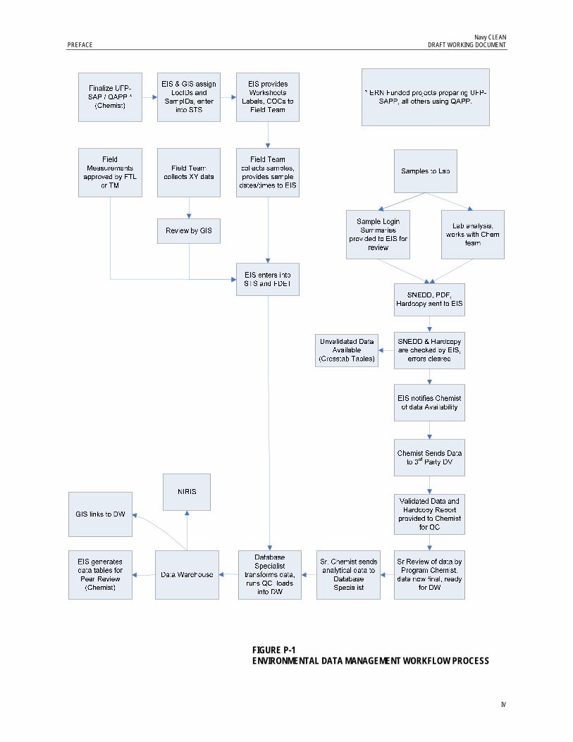
Navy CLEAN PREFACE DRAFT WORKING DOCUMENT
IV
FIGURE P-1 ENVIRONMENTAL DATA MANAGEMENT WORKFLOW PROCESS

Navy CLEAN PREFACE ATTORNEY-CLIENT PRIVILEGE DRAFT WORKING DOCUMENT
V
FIGURE P-2 DBMS PROCESS

VI
Contents
Preface .................................................................................................................................................. ii
Contents .............................................................................................................................................. vi
Acronyms and Abbreviations ...................................................................................................... viii
Introduction ........................................................................................................................ 1-1 1.1 Purpose .................................................................................................................... 1-1 1.2 Scope of the Data Management Plan .................................................................. 1-1
Roles and Responsibilities ............................................................................................... 2-1
Data Management System Description ......................................................................... 3-1
Phases of Data Management ............................................................................................ 4-1 4.1 Project Planning and Setup ................................................................................... 4-1
4.1.1 Database Setup and Administration ...................................................... 4-1 4.1.2 Data Security Procedures ......................................................................... 4-3 4.1.3 Data Backup and Recovery ...................................................................... 4-3
4.2 Sample Collection and Management .................................................................. 4-3 4.2.1 Sample Tracking Sheet ............................................................................. 4-4 4.2.2 Sample Nomenclature Guidelines .......................................................... 4-4 4.2.3 Sample Collection ..................................................................................... 4-1 4.2.4 Chain-of-Custody ..................................................................................... 4-1 4.2.5 Sample and Document Tracking ............................................................ 4-1 4.2.6 Field Data ................................................................................................... 4-1
4.3 Laboratory Analysis .............................................................................................. 4-2 4.4 Data Validation ...................................................................................................... 4-3
4.4.1 External Data Validation .......................................................................... 4-3 4.4.2 Internal Data Validation .......................................................................... 4-4 4.4.3 Unvalidated Data Preload Check ........................................................... 4-4 4.4.4 Senior Review ............................................................................................ 4-4
4.5 Data Preparation and Loading ............................................................................. 4-4 4.5.1 Data Preparation ....................................................................................... 4-5 4.5.2 Data Loading ............................................................................................. 4-5 4.5.3 Data Warehouse ........................................................................................ 4-6
4.6 Data Reporting ....................................................................................................... 4-6 4.6.1 Tables, Figures, and Diagrams ................................................................ 4-6 4.6.2 GIS ............................................................................................................... 4-7 4.6.3 Site Information Management System ................................................... 4-7 4.6.4 Legacy Data ............................................................................................... 4-7
Project Closeout .................................................................................................................. 5-1 5.1 Archive Procedures ............................................................................................... 5-1 5.2 Invoice Review and Approval ............................................................................. 5-1

Navy CLEAN TABLE OF CONTENTS DRAFT WORKING DOCUMENT
RDD/082520002 (DMP_NAVY-CLEAN_SNEDD_DRAFT_V1.DOCX) VII
5.3 Project Closeout ...................................................................................................... 5-2 Appendices
A RASCI/Workflow Process B Data Collection Flow Diagram C Standard Operating Procedures D Electronic Data Deliverable Specifications
Tables
Revision History ................................................................................................................................ iii
Table 1 ............................................................................................................................................... 2-2
Table 2 ............................................................................................................................................... 4-1 Table 3 ............................................................................................................................................... 4-1
Figures
Figure P-1 Environmental Data Management Workflow Process ........................................... iv
Figure P-2 DBMS Process ................................................................................................................. v
Figure 1 Environmental Data Management Workflow Process ............................................. 3-2
Figure 2 DBMS Process .................................................................................................................. 3-3
Figure 3 Project Planning ..................................................................................................................... 4-1
Figure 4 Field Sampling ................................................................................................................. 4-4
Figure 5 Laboratory Analysis ........................................................................................................ 4-2

VIII
Acronyms and Abbreviations
AFCEE Air Force Center for Engineering and the Environment
ALPTool Archive Load and Prep Tool
AM Activity Manager
CAD computer-aided design
COC chain-of-custody
DBMS Database Management System
DBS Database Specialist
EIS Environmental Information Specialist
DMP Data Management Plan
EDD electronic data deliverable
EDM Environmental Data Management
EMS Enterprise Management Solutions
ERP Environmental Restoration Program
ERPIMS Environmental Restoration Program Information Management System
EVS Environmental Visualization System
FD Field Duplicate
FDETool Field Data Entry Tool
FTL Field Team Leader
GA GIS Analyst
GIS geographic information system
ID identification
IDW investigation-derived waste
IRP Installation Restoration Program
MS matrix spike
MSD matrix spike duplicate
N/FD normal/field duplicate
NAVFAC Naval Facilities Engineering Command
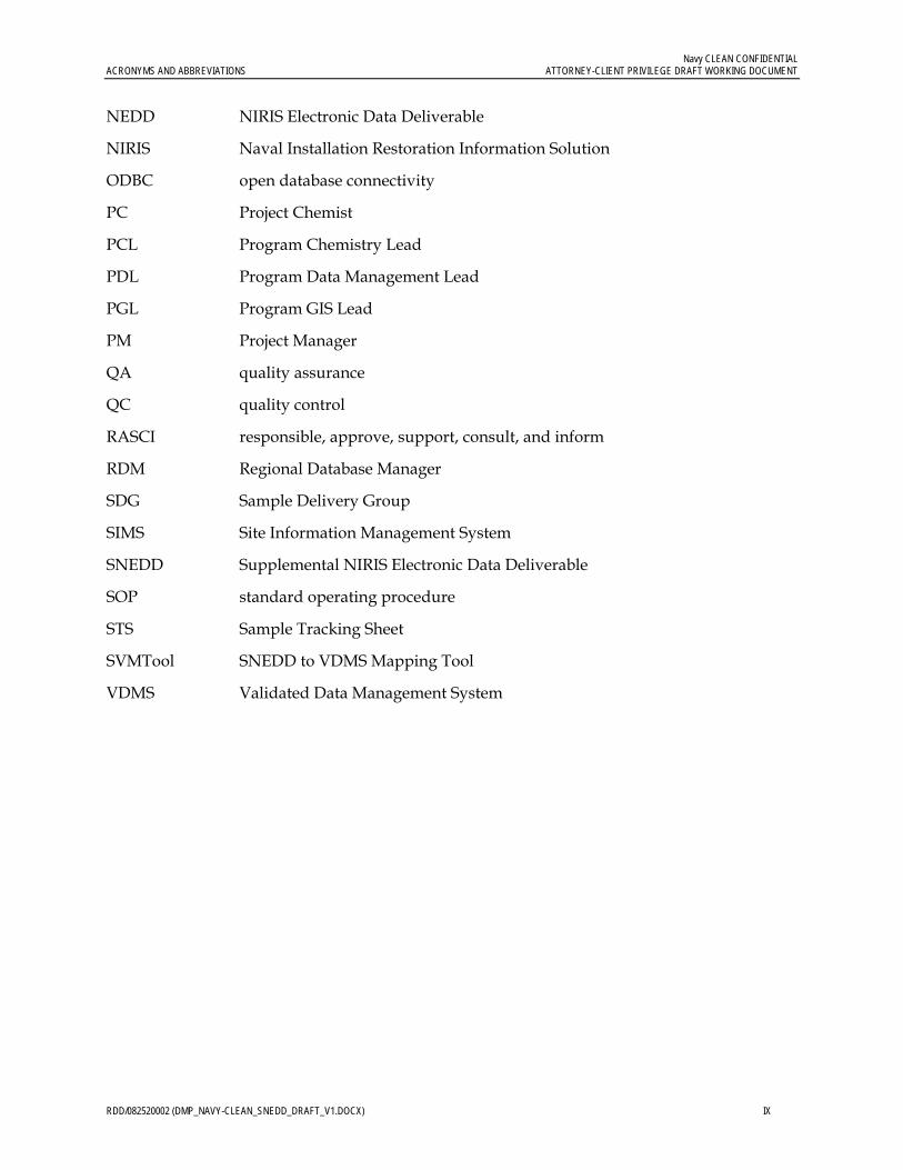
Navy CLEAN CONFIDENTIAL ACRONYMS AND ABBREVIATIONS ATTORNEY-CLIENT PRIVILEGE DRAFT WORKING DOCUMENT
RDD/082520002 (DMP_NAVY-CLEAN_SNEDD_DRAFT_V1.DOCX) IX
NEDD NIRIS Electronic Data Deliverable
NIRIS Naval Installation Restoration Information Solution
ODBC open database connectivity
PC Project Chemist
PCL Program Chemistry Lead
PDL Program Data Management Lead
PGL Program GIS Lead
PM Project Manager
QA quality assurance
QC quality control
RASCI responsible, approve, support, consult, and inform
RDM Regional Database Manager
SDG Sample Delivery Group
SIMS Site Information Management System
SNEDD Supplemental NIRIS Electronic Data Deliverable
SOP standard operating procedure
STS Sample Tracking Sheet
SVMTool SNEDD to VDMS Mapping Tool
VDMS Validated Data Management System

1-1
SECTION 1
Introduction
This Data Management Plan (DMP) describes the methods CH2M HILL will use to manage and present environmental data to support work it is conducting for the Navy CLEAN and Joint Venture Programs. These processes and procedures are part of an overall environmental data management system called the SNEDD Approach to the Validation Data Management System (VDMS), hosted by CH2M HILL.
Project members and any subcontractors supporting program data needs for site characterization and remediation activities can use this DMP. It is a living document that is flexible enough to meet the dynamic needs of the teams and stakeholders. Data management program details and procedures are included in the appendices.
1.1 Purpose This document outlines how environmental data for the Navy CLEAN and Joint Venture Programs will be obtained and managed using an Enterprise Management Solutions (EMS) approach. The systematic approach will facilitate the retrieval of data from project files and the data warehouse when they are needed, help ensure that the required data are collected and are of the appropriate quality, and help ensure that data records are not lost during transfer to the central program database repository.
1.2 Scope of the Data Management Plan The scope of the data management activities addressed by this plan includes the following:
Roles. Definition of staff roles and responsibilities.
Project Planning and Setup. Use standard templates and database applications; provide guidance and standard operating procedures (SOPs) for formatting, reviewing, and transferring data collected in the field to the Database Management System (DBMS).
Provide a structured, yet flexible data set. The DBMS will store all types of environmental data and provides a standard framework for all projects within the Navy CLEAN Program to use. The DBMS is organized and structured, yet flexible enough to allow additional data and data types to be added at any time over the life of the program.
Provide data that are well documented. The DBMS will retain enough descriptive and source information for technical defensibility and legal admissibility of the data.
Sample Collection and Management. Items that will be captured through standardized forms or applications include chains-of-custody (COCs), field parameter information, groundwater elevation data, and sample tracking records.
Laboratory Analysis. Laboratory data will be reported in the Supplemental Naval Installation Restoration Information Solution (NIRIS) Electronic Data Deliverable (SNEDD)

Navy CLEAN SECTION 1— INTRODUCTION DRAFT WORKING DOCUMENT
1-2
format specifications that analytical laboratories are required to use to transfer analytical data electronically to CH2M HILL. (Provided to laboratories via a scope of work.) Management and archive procedures will be implemented for hard copy and electronic project documentation.
Data Validation. Internal and external data validation will be conducted in accordance with the appropriate Program and EPA requirements. All deliverables will be subjected to Senior Review quality assurance (QA) and quality control (QC) measures. Management and archive procedures will be implemented for hard copy and electronic project documentation.
Data Management. QA and QC measures will be implemented to provide accurate representation of all data collected and to be stored in the DBMS. QA/QC procedures include restricting data import or entry to specific valid value lists that will not allow incorrect data to be included in the DBMS.
Data Evaluation and Reporting. Reporting and delivery support will be provided from a single DBMS source and allow relatively simple and rapid access to stored data for environmental characterization, report generation, modeling, geographic information system (GIS) mapping, statistical analyses, and risk assessments.
Provide data visualization capabilities. Data will be accurately represented for use in models, GIS, boring log programs (Environmental Visualization System [EVS), computer-aided design (CAD), graphics, and other software used for mapping, graphing, charting, analyzing, and displaying environmental data.
Provide the ability to compare data electronically. Tools will allow the electronic comparison of project data to specific reference or screening criteria.
Provide the ability to transfer data to different formats. The DBMS will provide the ability to reformat, convert, and transfer the data to any format as required by specific end-user applications.

2-1
SECTION 2
Roles and Responsibilities
The Navy CLEAN and Joint Venture Programs Environmental Data Management (EDM) team will work together to properly execute the DMP and ensure that the project objectives and scope are realized. The EDM team is composed of data management, chemistry, and GIS resources. The EDM team is responsible for all aspects of planning, execution, management and reporting environmental of data. Data are derived from sampling events related to investigative and remedial activities for Navy CLEAN and Joint Venture projects.
Responsibilities related to data management and information solutions functions are grouped into roles, as listed in Table 1. The SNEDD DM Process Checklist referenced in Appendix C documents the specific responsibilities associated with each of these roles.

Navy CLEAN SECTION 2—ROLES AND RESPONSIBILITIES DRAFT WORKING DOCUMENT
2-2
TABLE 1 Navy CLEAN and Joint Venture Environmental Data Management Program Team The Navy CLEAN Program Data Management Plan
Title Name/Address Phone Fax E-mail
Navy CLEAN Activity Manager (AM)
Various Various Various Various
Navy CLEAN Project Manager (PM)
Various Various Various Various
Field Team Leader (FTL) Various Various Various Various
Program Critigen Team Lead Mike Dierstein 5700 Cleveland Street Suite 101 Virginia Beach, VA 23462
757-671-6216 757-497-6885 [email protected]
Program Data Management Lead (PDL)
Chelsea Leigh 5700 Cleveland Street. Suite 101 Virginia Beach, VA 23462
757-671-6208 773-695-1378 [email protected]
Database Specialist (DBS) Bhavana Reddy 15010 Conference Center Dr. Suite 200 Chantilly, VA 20151
703- 462-3784 703- 376-5010 [email protected]
Program Chemistry Lead (PCL) Anita Dodson 5700 Cleveland Street Suite 101 Virginia Beach, VA 23462
757-671-6218 757-497-6885 [email protected]
Project Chemist (PC) Mike Zamboni 15010 Conference Center Dr. Suite 200 Chantilly, VA 20151
703-376-5111 703-376-5801 [email protected]
Project Chemist (PC) Megan Morrison 15010 Conference Center Dr. Suite 200 Chantilly, VA 20151
703-376-5053 703-376-5801 [email protected]

Navy CLEAN SECTION 2—ROLES AND RESPONSIBILITIES DRAFT WORKING DOCUMENT
2-3
TABLE 1 Navy CLEAN and Joint Venture Environmental Data Management Program Team The Navy CLEAN Program Data Management Plan
Title Name/Address Phone Fax E-mail
Project Chemist (PC) Bianca Kleist 5700 Cleveland Street. Suite 101 Virginia Beach, VA 23462
757-671-6281 757-497-6885 [email protected]
Project Chemist (PC) Juan Acaron 3011 S.W. Williston Road. Gainesville, FL 32608
352-384-7002- [email protected]
Project Chemist (PC) Kristina Lambert 3011 S.W. Williston Road. Gainesville, FL 32608
352-335-5877 [email protected]
Environmental Information Specialist (EIS)
Genevieve Moore 5700 Cleveland Street. Suite 101 Virginia Beach, VA 23462
757-671-6284 757-497-6885 [email protected]
Environmental Information Specialist (EIS)
Rebekha Shaw 5700 Cleveland Street. Suite 101 Virginia Beach, VA 23462
757-671-6279 757-497-6885 [email protected]
Environmental Information Specialist (EIS)
Gwendolyn Buckley 5700 Cleveland Street. Suite 101 Virginia Beach, VA 23462
757-671-8311 757-497-6885 [email protected]
Environmental Information Specialist (EIS)
Victoria Brynildsen 5700 Cleveland Street. Suite 101 Virginia Beach, VA 23462
757-671-6252 757-497-6885 [email protected]
Program GIS Lead (PGL) Mike Dierstein 5700 Cleveland Street. Suite 101 Virginia Beach, VA 23462
757-671-6216 757-497-6885 [email protected]

Navy CLEAN SECTION 2— ROLES AND RESPONSIBILITIES DRAFT WORKING DOCUMENT
2-4
TABLE 1 Navy CLEAN and Joint Venture Environmental Data Management Program Team The Navy CLEAN Program Data Management Plan
Title Name/Address Phone Fax E-mail
GIS Analyst (GA) Blake Hathaway 5700 Cleveland Street. Suite 101 Virginia Beach, VA 23462
757-671-6230 757-497-6885 [email protected]
GIS Analyst (GA) Mary Beth Artese 5700 Cleveland Street. Suite 101 Virginia Beach, VA 23462
757-671-6228 757-497-6885 [email protected]
GIS Analyst (GA) Mark Unwin 5700 Cleveland Street. Suite 101 Virginia Beach, VA 23462
757-671-6261 757-497-6885 [email protected]
GIS Analyst (GA) Chris Bowman 5700 Cleveland Street. Suite 101 Virginia Beach, VA 23462
757-671-6276 757-497-6885 [email protected]
GIS Analyst (GA) Matt Rissing 5700 Cleveland Street. Suite 101 Virginia Beach, VA 23462
757-671-6243 757-497-6885 [email protected]
GIS Analyst (GA) Forrest Cain 5700 Cleveland Street. Suite 101 Virginia Beach, VA 23462
757-671-6271 757-497-6885 [email protected]

3-1
SECTION 3
Data Management System Description
During field investigation, monitoring, and remedial activities, CH2M HILL will collect a variety of environmental information to support data analysis, reporting, and decision-making activities. To meet current regulatory QA requirements, a complete audit trail of the information flow must be implemented. The six steps in the workflow process are (Appendix B):
1. Project planning and database setup 2. Sample collection and management 3. Laboratory analysis 4. Data validation 5. Data management and loading 6. Data evaluation and reporting
Each step in the data management process must be adequately planned, executed, and documented. Figure 1 presents a simplified presentation of the workflow process specific to the Navy CLEAN and Joint Venture Programs. Figure 2 presents, in more detail, the tools used in each step of the process.

Navy CLEAN SECTION 3— DATA MANAGEMENT SYSTEM DESCRIPTION DRAFT WORKING DOCUMENT
3-2
FIGURE 1 ENVIRONMENTAL DATA MANAGEMENT WORKFLOW PROCESS

Navy CLEAN SECTION 3—DATA MANAGEMENT SYSTEM DESCRIPTION DRAFT WORKING DOCUMENT
3-3
FIGURE 2 DBMS PROCESS

4-1
SECTION 4
Phases of Data Management
4.1 Project Planning and Setup Project planning starts when a new project or task is identified in the program. Evaluation of what is required from data management and visualization occurs to determine the data needs. The Program Critigen Team Lead (Critigen Lead) works with the Program Data Management Lead (PDL) and the project and/or activity manager to determine what is expected and required from the data management and visualization team. Specific items that should be considered are as follows:
Inputs – Determine what data will be collected and stored in the database. Determine frequency and quantity. Determine what tools will be used to handle data input.
Historical Data – This is a unique data input and requires special consideration. The PDL must work with the other technical leads to assess what effort will be required. This step is often missed, and the resulting data quality issues created from inadequate planning in this area can plague the project for its entire duration.
Outputs – Determine what data will need to be presented in reports, figures, and electronic deliverables. Determine frequency and quality requirements. Determine preliminary data, validated data, and what tools will most effectively handle the output requirements. Discuss how the outputs needed by the team will be requested and documented.
Visualization – Determine necessity for GIS and CAD.
After the information above is determined, the data management scope, schedule, and budget are developed and endorsed by the Project Manager (PM), PDL, Program GIS Lead (PGL) and Program Chemistry Lead (PCL). The team can then proceed upon client authorization of the overall project budget. Figure 3 shows the process for project planning.
FIGURE 3 PROJECT PLANNING
4.1.1 Database Setup and Administration CH2M HILL Database The PDL will oversee the administration of the DBMS, including the design, development, and maintenance of the program database, tools and data management processes. Database and data management process design and development will focus on providing rapid data entry

Navy CLEAN CONFIDENTIAL SECTION 4— PHASES OF DATA MANAGEMENT DRAFT WORKING DOCUMENT
4-2
and data retrieval while promoting data integrity through various automated procedures. The PDL will perform the database maintenance, which consists of the following:
Assisting with the allocation of sufficient system storage for the program database
Adding, altering, and deleting users, roles, and privileges
Periodically defragmenting and compacting the database for more efficient operation
Upgrading database software and associated applications as necessary
Maintaining an approved list of valid values for data consistency
Maintaining redundancy control to ensure that each data record is unique and consistent with conventions
Performing routine virus checks on incoming and outgoing data
The DBMS is comprised of the Data Warehouse and associated SNEDD-Approach tools, and will support the storage, analysis, display, and reporting of the Navy’s environmental, analytical, and geotechnical data. The DBMS will consist of primary data tables that store the environmental data, dependent tables that store more details related to the data in the primary tables, and look-up tables that store valid values to provide input to the primary tables. The EIS will maintain the table content and the PDL will manage it.
Valid values are critical to any large relational database. Tables 2 and 3 provide examples of valid values for the Navy CLEAN and Joint Venture Programs’ sites, stations, and samples. Inconsistencies in naming conventions, subtle analyte or method spelling differences, and the use of non-standard abbreviations can result in lost data and incorrect conclusions. Most tables and forms in the program database will use look-up tables for acceptable valid values and will not allow the entry of data that do not conform.
The primary purpose of managing data in a relational database environment is to ensure that each data record is unique and that the information contained within each field is consistent with conventions defined in other areas of the database. To ensure that each record is unique, a key field or fields will be identified within each data table. The VDMS Data Warehouse architecture supports this approach and eliminates the possibility of data redundancy.
NIRIS Database All Navy CLEAN and Joint Venture data must be loaded into the Navy’s own internal database system, the Naval Installation Restoration Information Solution (NIRIS). NIRIS is a web-based centralized database that has been implemented across all Naval Facilities Engineering Command (NAVFAC) offices and will be used by the Navy and contractors to manage, evaluate, and visualize data, documents and records for Navy and the Marine Corps sites. NIRIS manages all Environmental Restoration Program (ERP) analytical and spatial data, which includes the Munitions Response and Installation Restoration Program (IRP) data, ensuring institutional memory is preserved, land use controls are maintained, and remedial actions are effective.
CH2M HILL will use the SNEDD Approach to VDMS system to track, collect, review, and prepare Navy-related sample and project data for loading into NIRIS. Project data stored in the

Navy CLEAN CONFIDENTIAL SECTION 4—PHASES OF DATA MANAGEMENT DRAFT WORKING DOCUMENT
4-3
VDMS Data Warehouse must be consistent and comparable with data that is loaded and stored within NIRIS. As such, all associations between VDMS and NIRIS valid values, output reports, and data tables will be tracked and maintained.
4.1.2 Data Security Procedures Some SNEDD Approach to VDMS applications and data are stored in a secure location with login and password protection. Authorized users will have logins and passwords in advance. The PDL will provide security access to these tools. Access2003 must be installed on the computer that the user will be using to run these applications, and proper licenses distributed. Files received from any subcontractors will be scanned for common viruses using industry standard, current virus protection programs. The file servers storing the data must be running current virus software, with automatic virus signature updates.
NIRIS data are stored in a secure location with login and password protection. Users who require access to NIRIS and the data contained therein will need to follow procedures outlined in the SOP Access to NIRIS to procure security certificates, training, and access rights to installation-specific data. Authorized users of NIRIS will be assigned logins and passwords maintained by the Navy. For further information on NIRIS or obtaining NIRIS access, consult with the Critigen Lead or PDL.
4.1.3 Data Backup and Recovery All project data management files will reside on CH2M HILL’s terminal server, “Gaia,” and will have a tape backup or equivalent created in accordance with CH2M HILL’s network server management policy.
4.2 Sample Collection and Management Sample control during the sampling phase is required to ensure the integrity of the associated data. Sample control must be maintained and documented from the point of collection through the point of disposal. Sample control will be managed both in the field and in the laboratory, and will be documented using field logbooks and a Chain of Custody (COC). When custody of a sample is transferred from one party to another, the recipient of the sample assumes responsibility for maintaining control of the sample and documenting that control on the COC. Figure 4 shows the process for planning and executing field sampling events.

Navy CLEAN CONFIDENTIAL SECTION 4— PHASES OF DATA MANAGEMENT DRAFT WORKING DOCUMENT
4-4
Finalize UFP-SAP / QAPP *
(Chemist)
EIS & GIS assign LocIDs and
SampIDs, enter into STS
EIS provides Worksheets
Labels, COCs to Field Team
Field Team collects samples, provides sample
dates/times to EIS
Field Team collects XY data
Review by GIS
EIS enters into STS and FDET
Field Measurements
approved by FTL or TM
Samples to Lab
FIGURE 4 FIELD SAMPLING
4.2.1 Sample Tracking Sheet During the planning stage, the PM specifies the data requirements for the sampling event. The work plan or similar document will provide project-specific data requirements for a given sampling event. The Project Chemist (PC) is responsible for reviewing the Sampling and Analysis Plan and ensuring that the FTL is aware of the number of field and laboratory QC samples required for the sampling event (trip blanks, equipment blanks, field blanks, field duplicates, matrix spikes, and matrix spike duplicates). All of this information is to be entered into the STS.
The STS will be used in advance to identify sampling container and preservation requirements, identify analytical laboratories for samples, aid in the generation of labels for sample bottles before the sampling event, and prepare COC forms after sampling is complete.
4.2.2 Sample Nomenclature Guidelines The following guidelines are provided for sample nomenclature, COC clarification, and eData expectations.
Station ID (Location) Field station data are information assigned to a physical location in the field at which some sort of sample is collected. For example, a monitoring well that has been installed will require a name that will uniquely identify it with respect to other monitoring wells or other types of sample locations. The station name provides a key in a database to which any samples collected from that location can be linked to form a relational database structure.
Before beginning fieldwork, the FTL will review the proposed level of effort and coordinate a list of unique station identification names, or station IDs, with the PDL or EIS. The FTL will be

Navy CLEAN CONFIDENTIAL SECTION 4—PHASES OF DATA MANAGEMENT DRAFT WORKING DOCUMENT
4-5
responsible for enforcing the use of the standardized ID system and agreed upon station IDs during all field activities.
Each station will be uniquely identified by an alphanumeric code that will describe the station’s attributes. These attributes are facility, Area of Concern (AOC)/Site/Operable Unit (OU) number, station type, sequential station number, and possibly an additional qualifier as needed. The naming scheme to be used for the identification of a sampling station is documented in Table 2.
For example, if the first sample location at next month’s event within Yorktown Site 30 is at a soil location, then the location ID could possibly be YS30-SO391 because that was the next available sequence number for soil locations. This should also be reflected in the Sample ID. QC and IDW station IDs must be established for each site that they are associated with.
Please consult with the PDL or EIS should any questions arise. This will avoid complications that could occur if a station is mislabelled and ensure there are unique identifiers for every sampling location. Required deviations to this format in response to field conditions will be documented in the field logbook.
Sample ID Field sample data are information assigned to a physical piece of material collected in the field for which some sort of analysis will be run. Before collecting samples, the FTL will review the proposed level of effort and coordinate a list of unique sample identification names, or sample IDs, with the PDL or EIS. The FTL will be responsible for enforcing the use of the standardized ID system and agreed upon sample IDs during all field activities.
Each sample will be uniquely identified by an alphanumeric code that will describe the sample’s attributes. These attributes are facility, Area of Concern (AOC)/Site/Operable Unit (OU) number, sample/station type, sequential station number, modifier (as needed), depth (as needed), date, and date modifier (as needed). The naming scheme to be used for the identification of samples is documented in Table 3.
The standardized ID system will identify all samples collected during sampling activities. The system will provide a tracking procedure to ensure accurate data retrieval of all samples taken. For example, a surface soil sample collected from station YS30-SO391 reference above in June of 2009 will result in a sample ID of YS30-SS391-0609.
Please consult with the PDL or EIS should any questions arise. This will avoid complications that could occur if a sample is mislabelled and ensure there are unique identifiers for every sample. Required deviations to this format in response to field conditions will be documented in the field logbook.
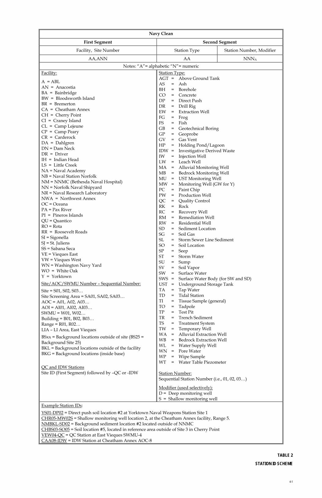
4-1
Navy Clean
First Segment Second Segment
Facility, Site Number Station Type Station Number, Modifier
AA,ANN AA NNNA
Notes: “A”= alphabetic “N”= numeric Facility:
A = ABL AN = Anacostia BA = Bainbridge BW = Bloodsworth Island BR = Bremerton CA = Cheatham Annex CH = Cherry Point CI = Craney Island CL = Camp Lejeune CP = Camp Peary CR = Carderock DA = Dahlgren DN = Dam Neck DR = Driver IH = Indian Head LS = Little Creek NA = Naval Academy NB = Naval Station Norfolk NM = NNMC (Bethesda Naval Hospital) NN = Norfolk Naval Shipyard NR = Naval Research Laboratory NWA = Northwest Annex OC = Oceana PA = Pax River PI = Pineros Islands QU = Quantico RO = Rota RR = Roosevelt Roads SI = Sigonella SJ = St. Juliens SS = Sabana Seca VE = Vieques East VW = Vieques West WN = Washington Navy Yard WO = White Oak Y = Yorktown
Site/AOC/SWMU Number – Sequential Number:
Site = S01, S02, S03… Site Screening Area = SA01, SA02, SA03… AOC = A01, A02, A03… AOI = AI01, AI02, AI03… SWMU = W01, W02… Building = B01, B02, B03… Range = R01, R02… LIA – LI Area, East Vieques
BSxx = Background locations outside of site (BS25 = Background Site 25) BKL = Background locations outside of the facility BKG = Background locations (inside base)
QC and IDW Stations Site ID (First Segment) followed by –QC or -IDW
Station Type: AGT = Above Ground Tank AS = Ash BH = Borehole CO = Concrete DP = Direct Push DR = Drill Rig EW = Extraction Well FG = Frog FS = Fish GB = Geotechnical Boring GP = Geoprobe GV = Gas Vent HP = Holding Pond/Lagoon IDW = Investigative Derived Waste IW = Injection Well LW = Leach Well MA = Alluvial Monitoring Well MB = Bedrock Monitoring Well MU = UST Monitoring Well MW = Monitoring Well (GW for Y) PC = Paint Chip PW = Production Well QC = Quality Control RK = Rock RC = Recovery Well RM = Remediation Well RW = Residential Well SD = Sediment Location SG = Soil Gas SL = Storm Sewer Line Sediment SO = Soil Location SP = Seep ST = Storm Water SU = Sump SV = Soil Vapor SW = Surface Water SWS = Surface Water Body (for SW and SD) UST = Underground Storage Tank TA = Tap Water TD = Tidal Station TI = Tissue Sample (general) TO = Tadpole TP = Test Pit TR = Trench Sediment TS = Treatment System TW = Temporary Well WA = Alluvial Extraction Well WB = Bedrock Extraction Well WL = Water Supply Well WN = Pore Water WP = Wipe Sample WT = Water Table Piezometer Station Number: Sequential Station Number (i.e., 01, 02, 03…)
Modifier (used selectively): D = Deep monitoring well S = Shallow monitoring well
Example Station IDs:
YS01-DP02 = Direct push soil location #2 at Yorktown Naval Weapons Station Site 1 CHR05-MW02S = Shallow monitoring well location 2, at the Cheatham Annex facility, Range 5. NMBKL-SD02 = Background sediment location #2 located outside of NNMC CHBS03-SO05 = Soil location #5, located in reference area outside of Site 3 in Cherry Point VEW04-QC = QC Station at East Vieques SWMU-4 CAA08-IDW = IDW Station at Cheatham Annex AOC-8
TABLE 2
STATION ID SCHEME

4-1
Navy Clean
First Segment Second Segment 3rd Segment Fourth Segment
Site ID Facility, AOC Number
Station/Sample Type, Station Number, Modifier
Depth (As Needed)
Date (MMYY) A
AA,ANN AANNNA A NNNNA
Notes: “A”= alphabetic “N”= numeric A = ABL AN = Anacostia BA = Bainbridge BW = Bloodsworth Island BR = Bremerton CA = Cheatham Annex CH = Cherry Point CI = Craney Island CL = Camp Lejeune CP = Camp Peary CR = Carderock DA = Dahlgren DN = Dam Neck DR = Driver IH = Indian Head LS = Little Creek NA = Naval Academy NB = Naval Station Norfolk NM = NNMC (Bethesda Naval Hospital) NN = Norfolk Naval Shipyard NR = Naval Research Laboratory NWA = Northwest Annex OC = Oceana PA = Pax River PI = Pineros Islands QU = Quantico RO = Rota RR = Roosevelt Roads SI = Sigonella SJ = St. Juliens SS = Sabana Seca VE = Vieques East VW = Vieques West WN = Washington Navy Yard WO = White Oak Y = Yorktown
Site/AOC/SWMU – Sequential Number:
Site = S01, S02, S03… Site Screening Area = SA01, SA02, SA03… AOC = A01, A02, A03… AOI = AI01, AI02, AI03… SWMU = W01, W02… Building = B01, B02, B03… Range = R01, R02… LIA – LI Area, East Vieques
BSxx = Background locations outside of site (BS25 = Background Site 25) BKL = Background locations outside of the facility BKG Background locations (inside base)
Sample Type: AGT = Above Ground Tank AH = Air - Headspace AS = Ash BH = Borehole CO = Concrete DR = Drill Rig DS = Direct Push—Soil DW = Direct Push—Groundwater EW = Extraction Well FG = Frog FS = Fish GB = Geotechnical Boring GP = Geoprobe GV = Gas Vent HP = Holding Pond/Lagoon IW = Injection Well LF = Free Product LW = Leach Well MA = Alluvial Monitoring Well MB = Bedrock Monitoring Well MU = UST Monitoring Well MW = Monitoring Well (GW for Y) PC = Paint Chip PW = Production Well RK = Rock SW = Surface Water RC = Recovery Well RM = Remediation Well RW = Residential Well SB = Subsurface Soil SD = Sediment Location SG = Soil Gas SL = Storm Sewer Line Sediment SO = Soil Location (Composite) SP = Seep SS = Surface Soil SSD = Subsurface Sediment ST = Storm Water SU = Sump SV = Soil Vapor SW = Surface Water UST = Underground Storage Tank TA = Tap Water TD = Tidal Station TI = Tissue Sample (general) TO = Tadpole TP = Test Pit TR = Trench Sediment TS = Treatment System TW = Temporary Well WA = Alluvial Extraction Well WB = Bedrock Extraction Well WL = Water Supply Well WN = Pore Water WP = Wipe Sample WT = Water Table Piezometer Station Number: Sequential Number (e.g., 001, 002, 003)
Modifier (used selectively): D = Deep monitoring well S = Shallow monitoring well P = Duplicate
Depth:
Use only if applicable. A sequential letter is used to reflect varying depths, as actual depths can change in the field after sample planning has occurred. E.g. A, B, C…
Sample Number:
1. Duplicate Samples - Use a ‘P’ modifier in the second segment of the sample ID, directly after the location number to indicate a duplicate sample. E.g. AB01-MW11P-0506
2. MS/MSD Samples – Append a modifier of ‘-MS’ for matrix spike or ‘-SD’ for matrix spike duplicate to the end of the sample ID.
3. QC & IDW Samples (Blank Samples & Waste Char.) - Format consists of Facility, AOC Number, Qualifier Code, Sequential Qualifier Number-Date (AAANN-AANN-MMDDYY). E.g. LSA05-TB02-061106
Qualifier Codes: TB = Trip Blank FB = Field Blank EB = Equipment Blank WQ = Source Blank WS = Waste Char. Soil WW = Waste Char. Water
4. Drill Rig Samples – Format consists of Facility, AOC Number, Station Type, Station Number, Date. E.g. YS12-DR02-020507
5. Multiple samples - Should multiple samples be collected from the same location in a given day/month (affects only samples not differentiated by depth), a sequential letter will be added to the end of the fourth segment (date). E.g. A, B, C…
Example Sample IDs:
WNA01-MW102S-0105A = The first shallow groundwater sample collected at monitoring well location 102 in January 2005 in AOC01 at the Washington Navy Yard facility. PIW01-SW023P-0306 = Pineros Island duplicate surface water sample collected at location 23, at SMWU-1 in March 2006. SSW06-FB01-061106 = The first field blank collected on June 11, 2006 at SMWU-6 in Sabana Seca.
TABLE 3
STATION ID SCHEME

Navy CLEAN CONFIDENTIAL SECTION 4— PHASES OF DATA MANAGEMENT DRAFT WORKING DOCUMENT
4-1
4.2.3 Sample Collection A photocopy of each field logbook page completed during sampling and of each COC will be made by the FTL and forwarded to the EIS at predefined intervals during sampling events. This information will serve as notification to the EIS of samples being shipped to an offsite lab and of the field crew’s sampling progress. Communication with field and laboratory staff will occur daily during the field event. The EIS will resolve issues that arise in the field (i.e. bottle ware shortage, equipment failure, etc). The lab will be informed of the shipment dates and the number of coolers or samples being sent. Laboratory login reports will be reviewed to ensure samples were received in good condition (i.e. no breakage, within holding time, within designated temperature). The field crew and PM will be notified if there were problems with shipment.
4.2.4 Chain-of-Custody A single COC number per laboratory / cooler should be generated each day (there can be multiple pages to one COC number). MSs and MSDs will be requested at a set frequency for each project (usually one per 20 samples collected). MS and MSD samples should not be taken from field duplicates (FDs) or field blanks. FDs will be requested at a set frequency for each project (usually one per 10 samples). FDs should not be taken from MSs, MSDs, or field blanks. The MS and MSD samples listed on the COC should be spiked and analyzed by the laboratory.
A 100% QC will be performed on COCs received from the field crew. The field crew and/or lab will be notified if corrections need to be made to the COCs or lab login reports. Any corrections or modifications made will be noted in a Corrections-To-File Letter.
4.2.5 Sample and Document Tracking The STS will be updated with sample collection and tracking information, and kept current throughout the data management process. All samples collected, resulting deliverables, and deliverable dates will be tracked throughout the data management process to ensure that the project schedule is met and subcontractor invoices are evaluated correctly. All documentation acquired during the data management process, including Statements of Work (SOWs), Bids, COCs, Field Notes, Sample Tracking Sheets, Login Reports, Corrections-to-File Letters, FDETool QC tables, Post Load Reports, Invoices, and Communication Logs shall be compiled throughout the process to be stored in the appropriate Activity’s Project Notebook.
4.2.6 Field Data Once the field data and samples are collected, necessary field measurements, such as water levels and other data collected in the field should be entered into the FDETool. Any data entered into the FDETool must be exported into an excel file to facilitate a manual QC review of the data. The correction of any anomalies should be verified with the PM and PC. The information entered into the FDETool will be linked with related analytical data reported in the SNEDD within the SVMTool. Field data and laboratory analytical data are linked by sample ID and date/time. This allows verification analytical results for all samples have been received and reported by the laboratory.

Navy CLEAN CONFIDENTIAL SECTION 4— PHASES OF DATA MANAGEMENT DRAFT WORKING DOCUMENT
4-2
4.3 Laboratory Analysis Figure 5 shows the laboratory analysis process. Upon receipt of samples from the field, the laboratory will verify that the COC forms correctly identify and detail all samples submitted. Each COC form must be signed with the date and time of receipt by the laboratory. Samples will be logged in by the laboratory using information from the COC forms and the project instructions.
FIGURE 5 LABORATORY ANALYSIS
Samples will be analyzed as specified on the accompanying COC forms and in the Laboratory SOW. Generally, questions or noted inconsistencies identified by the laboratory should be addressed directly to the EIS. Login summaries detailing all samples and analyses received by the lab should be provided daily to the EIS for review. All discrepancies should be corrected to ensure that all samples are analyzed as per project instructions.
The SNEDD-QC-Tool is used to QC the laboratory’s SNEDD. Before the laboratory analytical data is formatted into data tables or sent for validation, the laboratory SNEDD must be processed through CH2M Hill’s SNEDD-QC-Tool Microsoft Access database application. The SNEDD-QC-Tool includes several automated diagnostic checks to verify format and content compliance with SNEDD specifications.
The analytical laboratory may, at their discretion, utilize the tool to QC and correct any errors before transmitting the SNEDD to CH2M HILL. The laboratory will forward the checked SNEDD and a hard copy of the data to the EIS, who will manage the SNEDD verification process.
Upon receipt at CH2M Hill, the EIS will check the SNEDD using the SNEDD-QC-Tool to verify correct format and content. If errors are found, the laboratory will be notified of the errors, and the SNEDD corrected.

Navy CLEAN CONFIDENTIAL SECTION 4—PHASES OF DATA MANAGEMENT DRAFT WORKING DOCUMENT
4-3
The laboratory will attach the signed COCs to their hard copy data deliverables to officially relinquish control of the data back to the Environmental Contractor within the specified turnaround time. Data archiving forms will be generated and affixed to each laboratory report received per Sample Delivery Group (SDG) for cataloguing, tracking, and archiving purposes.
Hard copy data and SNEDDs will be reviewed to ensure that they are complete and acceptable as outlined in the Data QC Checklist. A 10% comparison between the hard copy and SNEDD content will be conducted to ensure consistency, resolve discrepancies, and document data error issues (for example, EDD re-submissions, turnaround time problems, hard copy incompleteness). All detected errors should be resolved with the laboratory. These checks ensure the consistency and the validity of the SNEDD and hardcopy content before the data are reported in preliminary tables or sent for validation. The objective of using the SNEDD-QC-Tool is to ensure that the validation process is performed on consistently high-quality data and minimize the chance of finding data errors later in the validation process, which would require the laboratory to resend corrected data and start the validation process over again.
Preliminary raw and detects tables will be generated from data reported in the SNEDD by the Navy RD Formatting Tool – Unval/Val SNEDD. A separate table must be created for each matrix, and provided to the PM for review.
4.4 Data Validation Once the preliminary data verification is complete, the PC is notified by the EIS that the data is available for validation. The PC will notify the data validator in advance of when to expect data and of any samples or analyses that should not be validated (i.e. grain size should not be validated). For internal data validation, the EIS will notify the PC of data availability, and provide the hardcopy data and a QC Association Table. Upon receipt of data from CH2M HILL, data validation will be performed in accordance with the Data Validation SOW, UFP SAP, and any other documents required. Generally, questions or noted inconsistencies identified by the validator should be addressed directly to laboratory, with the PC notified of issues and resolutions identified.
4.4.1 External Data Validation For external data validation, a copy of the SNEDD, hard copy data, and a QC Association Table will be provided to the data validator. The PC will coordinate the return of the data package to CH2M HILL for archiving with the data validator. Data Validators will provide the following materials to the PC within the required turn around time:
Hardcopy Data Validation Report Validated Version of the SNEDD (external validation)

Navy CLEAN CONFIDENTIAL SECTION 4— PHASES OF DATA MANAGEMENT DRAFT WORKING DOCUMENT
4-4
Once returned to CH2M HILL, the SNEDD will be run through the SNEDD-QC-Tool, which includes automated diagnostic checks for validated data to verify format and content compliance with SNEDD validation specifications. The PC will review the validated data to ensure that they are complete and acceptable as outlined in the Data QC Checklist. A 100% QC check will be performed on the validated results to ensure that the hard copy data matches the SNEDD. All detected errors should be resolved with the data validator. Data archiving forms will be generated and affixed to each Data Validation Report per SDG received for cataloguing, tracking, and archiving purposes. Validated raw and detects tables will be generated from data reported in the validated SNEDD by the Navy RD Formatting Tool – Unval/Val SNEDD. A separate table must be created for each matrix, and provided to the PM for review.
4.4.2 Internal Data Validation For internal data validation, a copy of the SNEDD, hard copy data, and a QC Association Table will be provided to the PC. The PC will evaluate QC information, associated validation logic, and apply qualifiers to data in the SNEDD and on the laboratory Form Is when QC criteria are not achieved. Qualifier criteria will be based on the Quality Assurance Project Plan. A hardcopy data validation report will be generated. Data archiving forms will be generated and affixed to each Data Validation Report per SDG validated for cataloguing, tracking, and archiving purposes Validated raw and detects tables will be generated from data reported in the validated SNEDD by the Navy RD Formatting Tool – Unval/Val SNEDD. A separate table must be created for each matrix, and provided to the PM for review.
4.4.3 Unvalidated Data Preload Check Occasionally, unvalidated data will need to be loaded into the database. Although the data will not be validated, it will undergo a basic Preload Check by the PC to ensure laboratory compliance with project guidelines and determine results to be reported as the best result where multiple runs were conducted for a given sample/analysis. The PCL will provide input and oversight to ensure that data flags are applied correctly by the PC.
4.4.4 Senior Review The PCL will verify that the final SNEDD and hardcopy data are complete and acceptable. Any identified discrepancies will be resolved with the assistance of the PC, EIS, laboratory, or validator as needed.
4.5 Data Preparation and Loading Once the data are considered final and approved by the PCL, they are exported from the SNEDD to the project Data Warehouse. Field and laboratory data are merged into a format that is amenable to the warehouse. The backbone is a SQL-server-based data warehouse.

Navy CLEAN CONFIDENTIAL SECTION 4—PHASES OF DATA MANAGEMENT DRAFT WORKING DOCUMENT
4-5
4.5.1 Data Preparation As part of the normal process of loading data into the warehouse, data standardization tasks must be completed. A Database Specialist (DBS) will load data into the warehouse using the following three programs: SNEDD-QC-Tool, SVMTool and CH-IMPTool.
A final QC of the data reported in the SNEDD is conducted with the SNEDD-QC-Tool. Any identified discrepancies will be resolved with the assistance of the PCL, PC, or EIS as needed. SNEDDs that pass all of the QA/QC checks in the SNEDD-QC-Tool are then processed with the SVMTool.
The SVMTool links the field data contained in the FDETool to the analytical data contained in the SNEDD. A series of logical QC checks are run to ensure that all data links correctly minimum data requirements are met. The tool then merges the data into a format compatible with the data warehouse structure.
4.5.2 Data Loading CH2M HILL Loading The CH-IMPTool runs an additional series of QC checks and adds project-specific formatting, and loads the data into the warehouse. The following tasks need to be completed to load the data for project use:
Unit Standardization: Analytical units and the associated results, reporting limits, and method detection limits will need to be converted to a consistent set of units as required by the project.
Resolve Reanalysis and Dilutions: All samples that had an associated reanalysis or dilution run by the laboratory must have all of the excluded or rejected results marked as not the best result for reporting.
Resolve Analytical Overlap and Split Samples: Analytical overlap occurs when a sample is analyzed by two or more methods that report the same analyte. To resolve any issues not previously resolved, the following logic is used to select the usable result:
If the overlapping results are all non-detections, the lowest non-detection result is selected.
If the overlapping results are all detected, the highest detected result is selected.
If the overlapping results consist of a mixture of detections and non-detections, the highest detected result is selected.
When data are loaded into the warehouse, an automated script will run to identify the “best” result when more than one analytical result exists.
NIRIS Loading All Navy CLEAN and Joint Venture data must be loaded into NIRIS. Following the successful loading of data into the data warehouse, the DBS will use the FDETool and ALPTool to generate project NIRIS Electronic Data Deliverables (NEDD) files. Field-related NEDDs will be generated from the final version of the FDETool. The final version of the project SNEDD will be processed through the ALPTool to generate the analytical NEDD.

Navy CLEAN CONFIDENTIAL SECTION 4— PHASES OF DATA MANAGEMENT DRAFT WORKING DOCUMENT
4-6
The DBS will use NIRIS’s Data Checker Loader Tool to QC and submit the project NEDD files into NIRIS. The NIRIS Regional Database Manager (RDM) will load the data into NIRIS, and will work with the DBS to resolve any potential issue that may arise during loading. Following notification of successful data loading from the RDM, the DBS will query the data from NIRIS for review to ensure data integrity and accuracy.
4.5.3 Data Warehouse The data warehouse is a Microsoft SQL Server 2005 relational database. This database, and all other “CH” tools used, has a data structure designed to achieve compliance with the Environmental Restoration Program Information Management System (ERPIMS) standard specified by Air Force Center for Engineering and the Environment (AFCEE). ERPIMS is an effective, comprehensive standard for environmental management.
The warehouse will use valid value tables when applying reference attributes to project data. Such reference data include the names of site objects and sampling locations, sampling matrix and method categories, analyte names, units. These reference tables are critical for maintaining the completeness and accuracy of data sets and are essential for accurate querying of the data.
Data are loaded and stored so that relationships among categories of data are enforced. For instance, all sampling records must be associated with a valid site object such as a planned sediment sampling location. The project repository database and collection, analysis, and reporting tools used in the DBMS are designed to enforce, for any project data record, entries in fields that refer to other types of data as required by the overall data model.
4.6 Data Reporting Data reporting includes the following tasks:
Retrieving data from the data warehouse for project deliverables, data visualization, or consumption by third parties
Reviewing initial data and producing data queries and draft reports to dissect and disassemble the data
Producing any requested client and regulatory agency data deliverables
Data for project deliverables, data visualization, or consumption by third parties will be retrieved from the warehouse, and will be equivalent to the real-time state of the project repository database. PMs and GIS Analysts (GAs) will work with the EIS and PCL for quality queries and data for reports.
4.6.1 Tables, Figures, and Diagrams Once the data have been sufficiently analyzed, the list of requested data reports (tables, figures, diagrams) can be developed and finalized by the project team and submitted to the PCL and PM for review.
All requests for figures or graphics are to be directed to the GA assigned as the Point of Contact (POC) for that particular Navy installation. All requests for analytical data (crosstab tables, data dumps, third party deliverables etc) should be directed to the EIS assigned as the POC for that particular Navy installation. The EIS will generate a data deliverable from the data warehouse
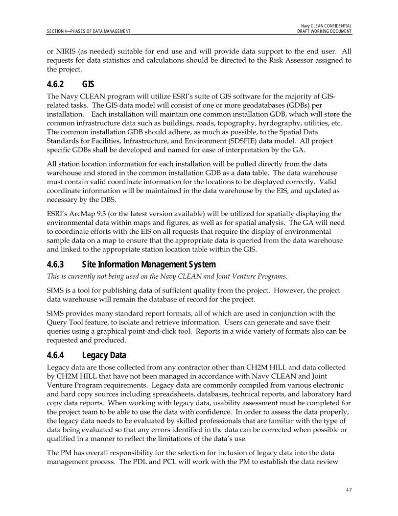
Navy CLEAN CONFIDENTIAL SECTION 4—PHASES OF DATA MANAGEMENT DRAFT WORKING DOCUMENT
4-7
or NIRIS (as needed) suitable for end use and will provide data support to the end user. All requests for data statistics and calculations should be directed to the Risk Assessor assigned to the project.
4.6.2 GIS The Navy CLEAN program will utilize ESRI’s suite of GIS software for the majority of GIS-related tasks. The GIS data model will consist of one or more geodatabases (GDBs) per installation. Each installation will maintain one common installation GDB, which will store the common infrastructure data such as buildings, roads, topography, hyrdography, utilities, etc. The common installation GDB should adhere, as much as possible, to the Spatial Data Standards for Facilities, Infrastructure, and Environment (SDSFIE) data model. All project specific GDBs shall be developed and named for ease of interpretation by the GA.
All station location information for each installation will be pulled directly from the data warehouse and stored in the common installation GDB as a data table. The data warehouse must contain valid coordinate information for the locations to be displayed correctly. Valid coordinate information will be maintained in the data warehouse by the EIS, and updated as necessary by the DBS.
ESRI’s ArcMap 9.3 (or the latest version available) will be utilized for spatially displaying the environmental data within maps and figures, as well as for spatial analysis. The GA will need to coordinate efforts with the EIS on all requests that require the display of environmental sample data on a map to ensure that the appropriate data is queried from the data warehouse and linked to the appropriate station location table within the GIS.
4.6.3 Site Information Management System This is currently not being used on the Navy CLEAN and Joint Venture Programs.
SIMS is a tool for publishing data of sufficient quality from the project. However, the project data warehouse will remain the database of record for the project.
SIMS provides many standard report formats, all of which are used in conjunction with the Query Tool feature, to isolate and retrieve information. Users can generate and save their queries using a graphical point-and-click tool. Reports in a wide variety of formats also can be requested and produced.
4.6.4 Legacy Data Legacy data are those collected from any contractor other than CH2M HILL and data collected by CH2M HILL that have not been managed in accordance with Navy CLEAN and Joint Venture Program requirements. Legacy data are commonly compiled from various electronic and hard copy sources including spreadsheets, databases, technical reports, and laboratory hard copy data reports. When working with legacy data, usability assessment must be completed for the project team to be able to use the data with confidence. In order to assess the data properly, the legacy data needs to be evaluated by skilled professionals that are familiar with the type of data being evaluated so that any errors identified in the data can be corrected when possible or qualified in a manner to reflect the limitations of the data’s use.
The PM has overall responsibility for the selection for inclusion of legacy data into the data management process. The PDL and PCL will work with the PM to establish the data review

Navy CLEAN CONFIDENTIAL SECTION 4— PHASES OF DATA MANAGEMENT DRAFT WORKING DOCUMENT
4-8
and import process, compile a comprehensive data inventory, and identify staff to facilitate data review.
The PDL and PCL will work with the EIS to determine the appropriate intermediary files and tools used to collect the data. The PDL and PCL will oversee the data review and flagging process and approve the data for upload into the Data Warehouse. The EIS is responsible for assembling the field and laboratory data in formats that facilitate data review, aid the PDL and PCL in overseeing the data review and flagging process, schedule, conversion of the data to the proper data warehouse format, and then loading the data into the Data Warehouse after approval by the PDL and PCL.
The GA, PDL, PCL, and PM have the primary responsibility for reviewing the data in their area of expertise and providing the PCL with data usability flags to be associated with each record.

5-1
SECTION 5
Project Closeout
The project completion/closeout phase includes the following:
Archive hard copy and electronic documents Conduct project closeout meeting
5.1 Archive Procedures A large variety of technical data will be generated during the field investigations. The EIS and PC will collect all hard copy and electronic data they are responsible for and verify that the incoming records are legible and in suitable condition for storage. Record storage will be performed in two stages:
Storage during the project Permanent storage following project completion
During the project, CH2M HILL will store data hardcopy reports in CH2M HILL offices. Physical records will be secured in steel file cabinets or shelves, and labelled with the appropriate project identification. Electronic data will be maintained on CH2M HILL’s corporate local area network servers.
Information generated from field activities will be documented on appropriate forms and will be maintained in the project file. These include COC records, field logbooks, well construction forms, boring logs, location sketches, and site photographs. In addition, notes from project meetings and telephone conversations will be filed.
Following project completion, both hard copy and electronic data deliverables will be archived. Team staff will provide all hard copies of laboratory and validation reports to the Data Closeout Coordinator to be prepped and shipped to Stone Mountain for archiving. Final laboratory SNEDDs and loading files will be provided to the PDL, to be archived on CH2M HILL’s corporate local area network servers.
Any modifications made to the tools will be communicated to the project team via e-mail. As revisions are finalized, they will be distributed electronically to all users. After revision, it is the user’s responsibility to conform to revised portions of the DMP.
5.2 Invoice Review and Approval The EIS is responsible for tracking all data deliverables throughout the data management process to ensure that the project schedule is maintained, subcontractors comply with all required turn around times, and data provided are complete and acceptable. Following project completion, EISs are to review and provide comments on all laboratory and data validator invoices regarding data quality and schedule compliance prior to approval by the PM.

Navy CLEAN CONFIDENTIAL SECTION 5— PROJECT CLOSEOUT DRAFT WORKING DOCUMENT
5-2
5.3 Project Closeout At the end of each project, the PM will notify team staff of project closeout. The PM will coordinate and verify that all pertinent data has been archived. The PM may also review lessons learned, suggest process improvements, or revisions to the DMP and other project documentation as deemed necessary.

Appendix A Environmental Data Management Work Process
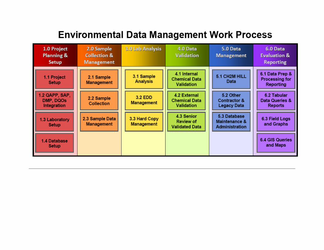

Appendix B Life of a Sample
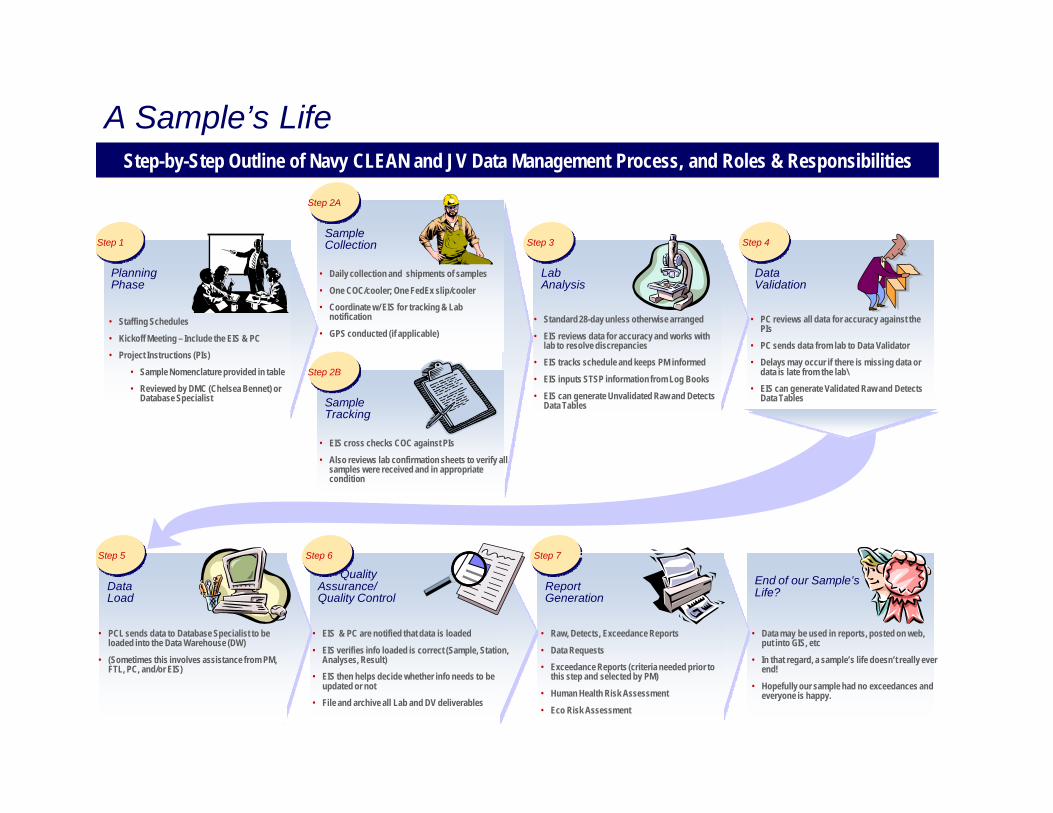
End of our Sample’s Life?
• Data may be used in reports, posted on web, put into GIS, etc
• In that regard, a sample’s life doesn’t really ever end!
• Hopefully our sample had no exceedances and everyone is happy.
• Raw, Detects, Exceedance Reports
• Data Requests• Exceedance Reports (criteria needed prior to
this step and selected by PM)
• Human Health Risk Assessment
• Eco Risk Assessment
Report Generation
Step 7
• EIS & PC are notified that data is loaded
• EIS verifies info loaded is correct (Sample, Station, Analyses, Result)
• EIS then helps decide whether info needs to be updated or not
• File and archive all Lab and DV deliverables
Quality Assurance/Quality Control
Step 6
Data Load
• PCL sends data to Database Specialist to be loaded into the Data Warehouse (DW)
• (Sometimes this involves assistance from PM, FTL, PC, and/or EIS)
Step 5
Data Validation
• PC reviews all data for accuracy against the PIs
• PC sends data from lab to Data Validator• Delays may occur if there is missing data or
data is late from the lab\• EIS can generate Validated Raw and Detects
Data Tables
Step 4
Lab Analysis
• Standard 28-day unless otherwise arranged
• EIS reviews data for accuracy and works with lab to resolve discrepancies
• EIS tracks schedule and keeps PM informed
• EIS inputs STSP information from Log Books
• EIS can generate Unvalidated Raw and Detects Data Tables
Step 3Sample Collection
• Daily collection and shipments of samples
• One COC/cooler; One FedEx slip/cooler• Coordinate w/ EIS for tracking & Lab
notification
• GPS conducted (if applicable)
Step 2A
Sample Tracking
• EIS cross checks COC against PIs
• Also reviews lab confirmation sheets to verify all samples were received and in appropriate condition
Step 2B
A Sample’s LifeStep-by-Step Outline of Navy CLEAN and JV Data Management Process, and Roles & Responsibilities
Planning Phase
• Staffing Schedules
• Kickoff Meeting – Include the EIS & PC• Project Instructions (PIs)
• Sample Nomenclature provided in table• Reviewed by DMC (Chelsea Bennet) or
Database Specialist
Step 1

Appendix C Standard Operating Procedures

Checklist – Archive and NIRIS Load Prep
Checklist – Data QC
Checklist - EIS Project Start-up Questions
Checklist - Generating RDE Tables
Checklist - Historic Data Cleanup
Checklist - SNEDD DM Process
Roles – Data Management Coordinator
Roles – EIS
Roles – Project Manager
Template – STS & QC Association Table
SOP-114 - CHIMPTool
SOP-126 - XTab Reports Tool
SOP - Access to NIRIS
SOP - Cherry Point Exceedance Formatting Wizard
SOP – CLEAN SNEDD Loading with CHIMPTool
SOP - Corrections to File
SOP - Data Archiving Procedures
SOP - Data Shipping
SOP – FDET
SOP – FDET Setup
SOP – NIRIS Importer Validator Tool
SOP – SVMTool
SOP – Valid Value Setup

Navy CLEAN CONFIDENTIAL SECTION 5—PROJECT CLOSEOUT DRAFT WORKING DOCUMENT
9
Appendix D Electronic Data Deliverable Specifications

CH2M HILL SNEDD Format Field Name Field Format REQ Field Description
Contract_ID A13 R
Contract ID assigned by Division Contracting Office, not including dashes. Found on Statement of Work. (e.g. D459559365800)
DO_CTO_Number A4 R CTO or TO # assigned by Navy. (e.g. CTO-12 = 0012, TO-54 = TO54)
Phase A8 NR Task Phase, SubTask Number or Annual Quarter. (e.g. QTR1)
Installation_ID A20* R Unique identifier for installation. (e.g. WHIDBEY) Sample_Name A50 R CH2M HILL Sample ID (from Chain Of Custody). CH2M_Code A4* R CH2M HILL Preparation Method Code (e.g. NONS)
Analysis_Group A9* R The CH2M HILL code for the analysis performed on the sample.
Analytical_Method A20* R Analytical Method used to analyze sample fraction. (e.g. 6010)
PRC_Code A15* R NIRIS code for the analytical method category (e.g. PCHAR)
Lab_Code A10* R CH2M HILL Code assigned to the laboratory (e.g. COMP)
Lab_Name A50* R The name of the laboratory that conducted the analysis, in all CAPS.
Leachate_Method A16* RA Code for the leachate method used on sample. (e.g. SW1310)
Sample_Basis A16* R Sample basis of analysis; wet weight, dry weight etc. (e.g. DRY)
Extraction_Method A16* RA Code for the extraction method used on sample. (e.g. FLTRES)
Result_Type A16* R Type of results; dilution, reanalysis etc. (e.g. 000) Lab_QC_Type A15* R Code for Laboratory Sample (MS, MSD, LBLK, LCS) Sample_Medium A16* R Sample medium reported by the laboratory. (e.g. L) QC_Level A16* R QC Level of data package : EPA levels I to IV. (e.g. 3)
DateTime_Collected MM/DD/YYYY
00:00 R Date and time sample was collected. Use 24 hour clock. (e.g. 02/13/2007 15:34)
Date_Received MM/DD/YYYY R The date the sample was received in the lab (in 10 characters). (e.g. 03/24/2007)
Leachate_Date YYYYMMDD RA
Date the sample was leached. Req'd if sample was leached and/or Leachate Method provided. (e.g. March 12, 2007 = 20070312)
Leachate_Time HH:MM:SS RA
Time the sample was leached. Use 24 hour clock, with 8 characters. (e.g. 14:30:05). Req'd if sample was leached and/or Leachate Method provided.
Extraction_Date YYYYMMDD RA Date that the lab extracted the sample. Req'd if Extraction Method provided.
Extraction_Time HH:MM:SS RA
Time of day lab extracted the sample. Use 24 hour clock, with 8 characters. Req'd if Extraction Method provided. (e.g. 02:15:00)
Analysis_Date YYYYMMDD R Date that the lab performed the analysis.
Analysis_Time HH:MM:SS R Time of day that the lab extracted the sample. Use 24 hour clock, with 8 characters.
Lab_Sample_ID A20 R Unique ID assigned to the sample by the laboratory.

CH2M HILL SNEDD Format Field Name Field Format REQ Field Description
Dilution N10,2 R Dilution factor used. Default value is 1 (e.g. 10)
Run_Number N4 R
Number distinguishing multiple or repeat analyses by the same method (incl. RA, RE, DL, etc). Must be equal to or greater than 1.
Percent_Moisture N6,3 RA Percent moisture of the sample. (e.g. 20) Percent_Lipid N6,3 RA Percent lipid of the sample. Chem_Name A55* R The name of the compound being analyzed.
Analyte_ID A20* R Analyte ID (CAS Number) assigned to the analyte. (e.g. 7440-47-3)
Analyte_Value N18,7 R Leave Blank for Validator to enter the final analyte concentration.
Original_Analyte_Value N18,7 R Analyte concentration value originally generated by the Laboratory.
Result_Units A16* R Unit of measure for the analyte value. (e.g. UG_L)
Lab_Qualifier A16* RA Lab data qualifier. Values will not be rejected if not in domain table.
Validator_Qualifier A16* RA Leave blank for Validator. Values will not be rejected if not in domain table.
GC_Column_Type A16* RA Data code for the type of GC column used in an analysis.
Analysis_Result_Type A4* R Type of analysis performed (allowed: SURR or TRG).
Result_Narrative A120 RA Additional information or comments associated with the result.
QC_Control_Limit_Code A16* RA Type of quality control limit. Req'd if QC criteria and upper/lower accuracy included. (e.g. CLPA)
QC_Accuracy_Upper N6,3 RA
Upper QC limit of % recovery as measured for a known target analyte spiked into a QC sample. (e.g. 25.45)
QC_Accuracy_Lower N6,3 RA
Lower QC limit of % recovery as measured for a known target analyte spiked into a QC sample. (e.g. 10.15)
Control_Limit_Date YYYYMMDD RA Date a control limit is established. QC_Narrative A120 RA Leave blank for Validator. Enter DV_Qual_Code. MDL N18,7 RA Method Detection Limit Detection_Limit N18,7 RA Reported Detection Limit
SDG A50 R Lab code for a group of samples in a data deliverable package.
Analysis_Batch A20 R Laboratory code for a batch of analyses analyzed together.
Validator_Name A50* R Leave Blank. Name of Validator in all CAPS. (e.g. CONTRACTOR INC.)
Val_Date YYYYMMDD RA Populated by Validator/Reviewer. Validation/Review QC date.

Attachment 4 DoD ELAP Accreditation Letter –
Analytical Laboratories

(A2LA Cert. No. 3000.01) Revised 09/26/2011 Page 1 of 8
SCOPE OF ACCREDITATION TO ISO/IEC 17025:2005
ENVIRONMENTAL CONSERVATION LABORATORIES – ORLANDO 10775 Central Port Drive
Orlando, FL 32824 Lori Mangrum Phone: 407 826 5314
ENVIRONMENTAL
Valid To: March 31, 2012 Certificate Number: 3000.01
In recognition of the successful completion of the A2LA evaluation process, (including an assessment of the laboratory's compliance with ISO IEC 17025:2005, the 2003 NELAC Chapter 5 Standard, and the requirements of the DoD Environmental Laboratory Accreditation Program (DoD ELAP) as detailed in the current DoD Quality Systems Manual for Environmental Laboratories) accreditation is granted to this laboratory to perform recognized EPA methods using the following testing technologies and in the analyte categories identified below:
Testing Technologies
Analyte / Parameter Non-Potable Water Solid Hazardous Waste Metals EPA 6020A/200.8 EPA 6020A Aluminum EPA 6020A/200.8 EPA 6020A Antimony EPA 6020A/200.8 EPA 6020A Arsenic EPA 6020A/200.8 EPA 6020A Barium EPA 6020A/200.8 EPA 6020A Beryllium EPA 6020A/200.8 EPA 6020A Cadmium EPA 6020A/200.8 EPA 6020A Calcium EPA 6020A/200.8 EPA 6020A Chromium EPA 6020A/200.8 EPA 6020A Cobalt EPA 6020A/200.8 EPA 6020A Copper EPA 6020A/200.8 EPA 6020A Hardness SM 2340 B ----------------------------------- Iron EPA 6020A/200.8 EPA 6020A Lead EPA 6020A/200.8 EPA 6020A Magnesium EPA 6020A/200.8 EPA 6020A Manganese EPA 6020A/200.8 EPA 6020A Mercury EPA 245.1/7470A EPA 7471B Molybdenum EPA 6020A/200.8 EPA 6020A Nickel EPA 6020A/200.8 EPA 6020A Potassium EPA 6020A/200.8 EPA 6020A Selenium EPA 6020A/200.8 EPA 6020A Silver EPA 6020A/200.8 EPA 6020A Sodium EPA 6020A/200.8 EPA 6020A Thallium EPA 6020A/200.8 EPA 6020A Tin EPA 6020A/200.8 EPA 6020A

(A2LA Cert. No. 3000.01) Revised 09/26/2011 Page 2 of 8
Analyte / Parameter Non-Potable Water Solid Hazardous Waste Titanium EPA 6020A/200.8 EPA 6020A Vanadium EPA 6020A/200.8 EPA 6020A Zinc EPA 6020A/200.8 EPA 6020A Microbiology Total Coliforms SM 9222B ----------------------------------- Fecal Coliforms SM 9222D ----------------------------------- General Chemistry Acidity, as CaC03 EPA 305.1/SM 2310 B (4A) ----------------------------------- Alkalinity as CaC03 EPA 310.1/SM 2320 B EPA 310.1/SM 2320 B Alkalinity as CaC04 EPA 310.2 EPA 310.2 Ammonia as N ----------------------------------- EPA 350.1 Biochemical oxygen demand EPA 405.1/SM 5210 B ----------------------------------- Bromide EPA 300.0/9056A EPA 9056A Carbonaceous BOD (CBOD) SM 5210 B ----------------------------------- Chemical oxygen demand EPA 410.4 ----------------------------------- Chloride EPA 300.0/9056A EPA 9056A Chromium VI EPA 7196/ SM 3500-Cr D EPA 7196 Conductivity EPA 120.1 ----------------------------------- Cyanide EPA 335.2/SM 4500-CN E EPA 9014 Ferric iron (calculated) SM 3500-Fe D ----------------------------------- Ferrous iron SM 3500-Fe D ----------------------------------- Fluoride EPA 300.0/9056A EPA 9056A Hardness EPA 130.2/SM 2340 C ----------------------------------- Kjeldahl nitrogen -total EPA 351.2 EPA351.2 Nitrate as N EPA 300.0/353.1/9056A EPA 353.1/9056A Nitrate-nitrite EPA 300.0/353.1/9056A EPA 353.1/9056A
Nitrite as N EPA 300.0/354.1/9056A/SM 4500-NO2 B EPA 9056A/ SM 4500-NO2 B
Organic nitrogen EPA 351.2/350.1 EPA 351.2/350.1 Orthophosphate as P EPA 365.1 ----------------------------------- Orthophosphate as P EPA 365.3 ----------------------------------- pH EPA 150.1/9040C/SM 4500-H+-B EPA 9040C Phosphorus, total EPA 365.4 EPA 365.4 Residue-filterable (TDS) SM 2540 C ----------------------------------- Residue-nonfilterable (TSS) SM 2540 D ----------------------------------- Residue-total SM 2540 B/SM 2540 G/EPA 160.3 SM 2540G/EPA 160.3 Residue-volatile EPA 160.4 EPA 160.4 Sulfate EPA 300.0/9056A EPA 9056A Sulfide EPA 376.1/SM 4500-S E ----------------------------------- Surfactants -MBAS SM 5540 C ----------------------------------- Total nitrate-nitrite EPA 9056 A/SM 4500-N03 H EPA 9056 A/SM 4500-N03 H Total cyanide EPA 9014 EPA 9014 Total nitrogen TKN + Total nitrate-nitrite TKN + Total nitrate-nitrite Total Organic Carbon EPA 9060A/SM 5310B TOC Walkley Black Total phenolics EPA 420.1 EPA 420.1 Total, fixed, and volatile residue SM 2540 G SM 2540 G Turbidity EPA 180.1 ----------------------------------- Un-ionized ammonia DEP SOP 10/03/83 DEP SOP 10/03/83 Extractable Organics

(A2LA Cert. No. 3000.01) Revised 09/26/2011 Page 3 of 8
Analyte / Parameter Non-Potable Water Solid Hazardous Waste 1,2,4-Trichlorobenzene EPA 8270D/625 EPA 8270D 1,2,4,5-Tetrachlorobenzene EPA 8270D/625 EPA 8270D 1,2-Dichlorobenzene EPA 8270D/625 EPA 8270D 1,2-Diphenylhydrazine EPA 8270D/625 EPA 8270D 1,3-Dichlorobenzene EPA 8270D/625 EPA 8270D 1,4-Dichlorobenzene EPA 8270D/625 EPA 8270D 1- Methylnaphthalene EPA 8270D/625/ Scan-Sim EPA 8270D/ Scan-Sim 2,3,4,6-Tetrachlorophenol EPA 8270D/625 EPA 8270D 2,4,5-Trichlorophenol EPA 8270D/625 EPA 8270D 2,4,6-Trichlorophenol EPA 8270D/625 EPA 8270D 2,4-Dichlorophenol EPA 8270D/625 EPA 8270D 2,4-Dimethylphenol EPA 8270D/625 EPA 8270D 2,4-Dinitrophenol EPA 8270D/625 EPA 8270D 2,4-Dinitrotoluene (2,4-DNT) EPA 8270D/625/ Scan-Sim EPA 8270D 2,6-Dichlorophenon EPA 8270D/625 EPA 8270D 2,6-Dinitrotoluene (2,6-DNT) EPA 8270D/625 EPA 8270D 2-Chloronaphthalene EPA 8270D/625 EPA 8270D 2-Chlorophenol EPA 8270D/625 EPA 8270D 2·Methyl-4,6-dinitrophenol EPA 8270D/625 EPA 8270D 2-Methylnaphthalene EPA 8270D/625 Scan-Sim EPA 8270D Scan-Sim 2-Methylphenol (o-Cresol) EPA 8270D/625 EPA 8270D 2-Nitroaniline EPA 8270D/625 EPA 8270D 2-Nitrophenol EPA 8270D/625 EPA 8270D 3,3'-Dichlorobenzidine EPA 8270D/625 EPA 8270D 3/4-Methylphenols (m/p-Cresols) EPA 8270D/625 EPA 8270D 3-Nitroaniline EPA 8270D/625 EPA 8270D 4-Bromophenyl phenyl ether EPA 8270D/625 EPA 8270D 4-Chloro-3-methylphenol EPA 8270D/625 EPA 8270D 4-Chloroaniline EPA 8270D/625 EPA 8270D 4-Chlorophenyl phenyl ether EPA 8270D/625 EPA 8270D 4-Nitrophenol EPA 8270D/625 EPA 8270D Acenaphthene EPA 8270D/625 Scan-Sim EPA 8270D Scan-Sim Acenaphthylene EPA 8270D/625 Scan-Sim EPA 8270D Scan-Sim 4-Melhylphenol (p-Cresol) EPA 8270D/625 EPA 8270D 4-Nitroaniline EPA 8270D/625 EPA 8270D Acetophenone EPA 8270D/625 EPA 8270D Anthracene EPA 8270D/625/ Scan-Sim EPA 8270D Scan Sim Atrazine EPA 8270D/625 EPA 8270D Benzaldehyde EPA 8270D/625 EPA 8270D Benzidine EPA 8270D/625/ Scan-Sim EPA 8270D Benzo(a)anthracene EPA 8270D/625/ Scan-Sim EPA 8270D Scan-Sim Benzo(a)pyrene EPA 8270D/625/ Scan-Sim EPA 8270D Scan-Sim Benzo(b)fluoranthene EPA 8270D/625/ Scan-Sim EPA 8270D Scan-Sim Benzo(g,h,i)perylene EPA 8270D/625/ Scan-Sim EPA 8270D Scan-Sim Benzo(k)fluoranthene EPA 8270D/625/ Scan-Sim EPA 8270D Scan-Sim Benzyl alcohol EPA 8270D/625 EPA 8270D 1,1-Biphenyl EPA 8270D/625 EPA 8270D bis(2-Chloroethoxy) methane EPA 8270D/625 EPA 8270D bis(2-Chloroethyl) ether
EPA 8270D/625
EPA 8270D
bis(2-Chloroisopropyl) ether (2,2'-Oxybis(1-chloropropane)) EPA 8270D/625 EPA 8270D

(A2LA Cert. No. 3000.01) Revised 09/26/2011 Page 4 of 8
Analyte / Parameter Non-Potable Water Solid Hazardous Waste bis(2-Ethylhexyl) phthalate (DEHP) EPA 8270D/625 EPA 8270D Butyl benzyl phthalate EPA 8270D/625 EPA 8270D Caprolactam EPA 8270D/625 EPA 8270D Carbazole EPA 8270D/625 EPA 8270D Chrysene EPA 8270D/625/ Scan-Sim EPA 8270D Scan-Sim Dibenz(a,h)anthracene EPA 8270D/625/ Scan-Sim EPA 8270D Scan-Sim Dibenzofuran EPA 8270D/625 EPA 8270D
Diethyl phthalate EPA 8270D/625 EPA 8270D Dimethyl phthalate EPA 8270D/625/ Scan-Sim EPA 8270D Di-n-butyl phthalate EPA 8270D/625 EPA 8270D Di-n-octyl phthalate EPA 8270D/625 EPA 8270D Fluoranthene EPA 8270D/625/ Scan-Sim EPA 8270D Scan-Sim Fluorene EPA 8270D/625 Scan-Sim EPA 8270D Scan-Sim Hexachlorobenzene EPA 8270D/625/ Scan-Sim EPA 8270D Hexachlorobutadiene EPA 8270D/625/ Scan-Sim EPA 8270D Hexachlorocyclopentadiene EPA 8270D/625 EPA 8270D Hexachloroethane EPA 8270D/625 EPA 8270D Indeno(1,2,3-cd)pyrene EPA 8270D/625/ Scan-Sim EPA 8270D Scan-Sim Isodrin EPA 8270D/625 EPA 8270D Isophorone EPA 8270D/625 EPA 8270D Naphthalene EPA 8270D/625 Scan-Sim EPA 8270D Scan-Sim Nitrobenzene EPA 8270D/625 EPA 8270D n-Nitrosodimethylamine EPA 8270D/625 EPA 8270D n-Nitrosodi-n-propylamine EPA 8270D/625 EPA 8270D n-Nitrosodiphenylamine EPA 8270D/625 EPA 8270D n-Nitrosopyrrolidine EPA 8270D/625 EPA 8270D Pentachlorophenol EPA 8270D/625/ Scan-Sim EPA 8270D Phenanthrene EPA 8270D/625 Scan-Sim EPA 8270D Scan-Sim Phenol EPA 8270D/625 EPA 8270D Pyrene EPA 8270D/625 Scan-Sim EPA 8270D Scan-Sim Total Petroleum Hydrocarbons (TPH) FL·PRO FL·PRO Volatile Organics 1,1,1,2-Tetrachloroethane EPA 8260B/624 EPA 8260B 1,1,1-Trichloroethane EPA 8260B/624 EPA 8260B 1,1,2,2-Tetrachloroethane EPA 8260B/624 EPA 8260B 1,1,2-Trichloro-1,2,2-trifluoroethane EPA 8260B/624 EPA 8260B 1,1,2-Trichloroethane EPA 8260B/624 EPA 8260B 1,1-Dichloroethane EPA 8260B/624 EPA 8260B 1,1-Dichloroethene EPA 8260B/624 EPA 8260B 1,1-Dichloropropene EPA 8260B/624 EPA 8260B 1,2,3-Trichlorobenzene EPA 504.1/8260B/624 EPA 8260B 1,2,3-Trichloropropane EPA 8260B/624 EPA 8260B 1,2,4-Trichlorobenzene EPA 8260B/624 EPA 8260B 1,2,4-Trimethylbenzene EPA 8260B/624 EPA 8260B 1,2-Dibromo-3-chloropropane (DBCP) EPA 504 /504.1/8011/8260B EPA 8260B 1,2-Dibromoethane (EDB, Ethylene dibromide) EPA 504 /504.1/8011/8260B EPA 8260B

(A2LA Cert. No. 3000.01) Revised 09/26/2011 Page 5 of 8
Analyte / Parameter Non-Potable Water Solid Hazardous Waste 1,2-Dichlorobenzene EPA 8260B/624 EPA 8260B 1,2-Dichloroethane EPA 8260B/624 EPA 8260B 1,2-Dichloropropane EPA 8260B/624 EPA 8260B 1,3,5-Trimethylbenzene EPA 8260B/624 EPA 8260B 1,3-Dichlorobenzene EPA 8260B/624 EPA 8260B 1,3-Dichloropropane EPA 8260B/624 EPA 8260B 1,4-Dichlorobenzene EPA 8260B/624 EPA 8260B 1,4-Dioxane (1,4-Diethylencoxide) EPA 8260B/8260C SIM/624 EPA 8260B/8260C SIM 2,2-Dichloropropane EPA 8260B/624 EPA 8260B 2-Butanone (Methyl ethyl ketone, MEK) EPA 8260B/624 EPA 8260B 2-Chloroethyl vinyl ether EPA 8260B/624 EPA 8260B 2-Chlorotoluene EPA 8260B/624 EPA 8260B 2-Hexanone EPA 8260B/624 EPA 8260B 4-Chlorotoluene EPA 8260B/624 EPA 8260B 4-Methyl-2-pentanone (MIBK) EPA 8260B/624 EPA 8260B Acetone EPA 8260B/624 EPA 8260B Acetonitrile EPA 8260B/624 EPA 8260B Acrolein (Propenal) EPA 8260B/624 EPA 8260B Acrylonitrile EPA 8260B/624 EPA 8260B Allyl chloride (3-Chloropropene) EPA 8260B/624 EPA 8260B Benzene EPA 8260B/624 EPA 8260B Bromobenzene EPA 8260B/624 EPA 8260B Bromochloromethane EPA 8260B/624 EPA 8260B Bromodichloromethane EPA 8260B/624 EPA 8260B Bromoform EPA 8260B/624 EPA 8260B Carbon tetrachloride EPA 8260B/624 EPA 8260B Carbon disulfide EPA 8260B/624 EPA 8260B Chlorobenzene EPA 8260B/624 EPA 8260B Chloroethane EPA 8260B/624 EPA 8260B Chloroform EPA 8260B/624 EPA 8260B Chloroprene EPA 8260B/624 EPA 8260B cis-1,2-Dichloroethene EPA 8260B/624 EPA 8260B cis-1,3-Dichloropropene EPA 8260B/624 EPA 8260B Cyclohexane EPA 8260B/624 EPA 8260B Dibromochloromethane EPA 8260B/624 EPA 8260B Dibromomethane EPA 8260B/624 EPA 8260B Dichlorodifluoromethane EPA 8260B/624 EPA 8260B Ethyl methacrylate EPA 8260B/624 EPA 8260B Hexachlorobutadiene EPA 8260B/624 EPA 8260B Ethylbenzene EPA 8260B/624 EPA 8260B Iodomethane (Methyl iodide) EPA 8260B/624 EPA 8260B Isobutyl alcohol (2-Methyl-l-propanol) EPA 8260B/624 EPA 8260B Isopropylbenzene EPA 8260B/624 EPA 8260B m+p-Xylenes EPA 8260B/624 EPA 8260B Methacrylonitrile EPA 8260B/624 EPA 8260B Methyl acetate EPA 8260B/624 EPA 8260B Methyl bromide (Bromomethane) EPA 8260B/624 EPA 8260B Methyl chloride (Chloromethane) EPA 8260B/624 EPA 8260B Methyl methacrylate EPA 8260B/624 EPA 8260B Methyl tert-butyl ether (MTBE) EPA 8260B/624 EPA 8260B

(A2LA Cert. No. 3000.01) Revised 09/26/2011 Page 6 of 8
Analyte / Parameter Non-Potable Water Solid Hazardous Waste Methylcyclohexane EPA 8260B/624 EPA 8260B Methylene chloride EPA 8260B/624 EPA 8260B Naphthalene EPA 8260B/624 EPA 8260B n-Butylbenzene EPA 8260B/624 EPA 8260B n-Propylbenzene EPA 8260B/624 EPA 8260B o-Xylene EPA 8260B/624 EPA 8260B Pentachloroethane EPA 8260B/624 EPA 8260B p-Isopropyltoluene EPA 8260B/624 EPA 8260B Propionitrile (Ethyl cyanide) EPA 8260B/624 EPA 8260B sec-Butylbenzene EPA 8260B/624 EPA 8260B Styrene EPA 8260B/624 EPA 8260B tert-Butylbenzene EPA 8260B/624 EPA 8260B Tetrachloroethene (Perchloroethylene) EPA 8260B/624 EPA 8260B Toluene EPA 8260B/624 EPA 8260B trans-1,2-Dichloroethene EPA 8260B/624 EPA 8260B trans-1,3-Dichloropropene EPA 8260B/624 EPA 8260B trans-1,4-Dichloro-2-butene EPA 8260B/624 EPA 8260B Trichloroethene (Trichloroethylene) EPA 8260B/624 EPA 8260B Trichlorofluoromethane EPA 8260B/624 EPA 8260B Vinyl acetate EPA 8260B/624 EPA 8260B Vinyl chloride EPA 8260B/624 EPA 8260B Xylene (total) EPA 8260B/624 EPA 8260B Pesticides-Herbicides-PCBs 2,4,5-T EPA 8151A /615 EPA 8151A 2,4-D EPA 8151A /615 EPA 8151A 2,4-DB EPA 8151A /615 EPA 8151A 3,5-Dichlorobenzoic acid EPA 8151A /615 EPA 8151A 4.4'-DDD EPA 8081B/608 EPA 8081B 4.4'-DDE EPA 8081B/608 EPA 8081B 4,4'·DDT EPA 8081B/608 EPA 8081B 4-Nitrophenol EPA 8151A/615 EPA 8151A Acifluorfen EPA 8151A/615 EPA 8151A Aldrin EPA 8081B/608 EPA 8081B alpha-BHC (alpha-Hexachlorocyclohexane) EPA 8081B/608 EPA 8081B alpha-Chlordane EPA 8081B/608 EPA 8081B Aroclor-1016(PCB-1016) EPA 8082A/608 EPA 8082A Aroclor-1221 (PCB-1221) EPA 8082A/608 EPA 8082A Aroclor-1232 (PCB-1232) EPA 8082A/608 EPA 8082A Aroclor-1242 (PCB-1242) EPA 8082A/608 EPA 8082A Aroclor-1248 (PCB-1248) EPA 8082A/608 EPA 8082A Aroclor-1254 (PCB-1254) EPA 8082A/608 EPA 8082A Aroclor-1260 (PCB-1260) EPA 8082A/608 EPA 8082A Aroclor-1262 (PCB-1262) EPA 8082A/608 EPA 8082A Aroclor-1268 (PCB-1268) EPA 8082A/608 EPA 8082A Azinphos-methyl (Guthion) EPA 8141B/614 EPA 8141B Bentazon EPA 8151A/615 EPA 8151A beta-BHC (beta-Hexachlorocyclohexane) EPA 8081B/608 EPA 8081B Bolstar (Sulprofos) EPA 8141B/614 EPA 8141B
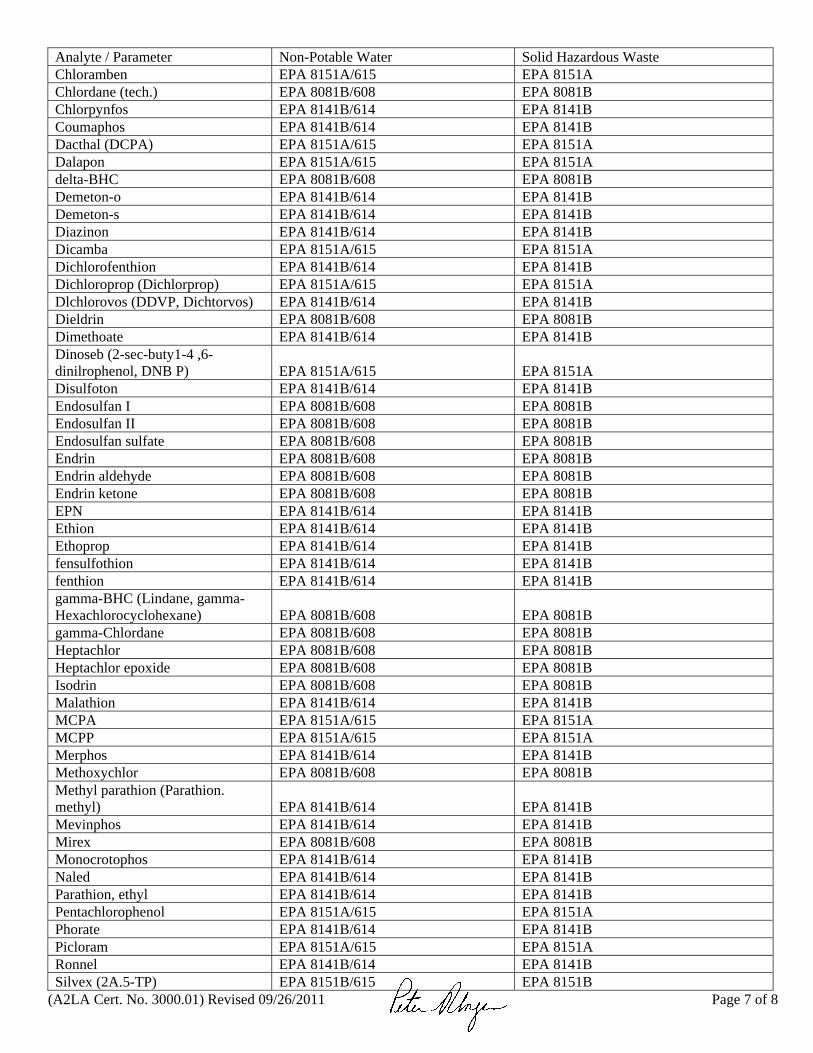
(A2LA Cert. No. 3000.01) Revised 09/26/2011 Page 7 of 8
Analyte / Parameter Non-Potable Water Solid Hazardous Waste Chloramben EPA 8151A/615 EPA 8151A Chlordane (tech.) EPA 8081B/608 EPA 8081B Chlorpynfos EPA 8141B/614 EPA 8141B Coumaphos EPA 8141B/614 EPA 8141B Dacthal (DCPA) EPA 8151A/615 EPA 8151A Dalapon EPA 8151A/615 EPA 8151A delta-BHC EPA 8081B/608 EPA 8081B Demeton-o EPA 8141B/614 EPA 8141B Demeton-s EPA 8141B/614 EPA 8141B Diazinon EPA 8141B/614 EPA 8141B Dicamba EPA 8151A/615 EPA 8151A Dichlorofenthion EPA 8141B/614 EPA 8141B Dichloroprop (Dichlorprop) EPA 8151A/615 EPA 8151A Dlchlorovos (DDVP, Dichtorvos) EPA 8141B/614 EPA 8141B Dieldrin EPA 8081B/608 EPA 8081B Dimethoate EPA 8141B/614 EPA 8141B Dinoseb (2-sec-buty1-4 ,6-dinilrophenol, DNB P) EPA 8151A/615 EPA 8151A Disulfoton EPA 8141B/614 EPA 8141B Endosulfan I EPA 8081B/608 EPA 8081B Endosulfan II EPA 8081B/608 EPA 8081B Endosulfan sulfate EPA 8081B/608 EPA 8081B Endrin EPA 8081B/608 EPA 8081B Endrin aldehyde EPA 8081B/608 EPA 8081B Endrin ketone EPA 8081B/608 EPA 8081B EPN EPA 8141B/614 EPA 8141B Ethion EPA 8141B/614 EPA 8141B Ethoprop EPA 8141B/614 EPA 8141B fensulfothion EPA 8141B/614 EPA 8141B fenthion EPA 8141B/614 EPA 8141B gamma-BHC (Lindane, gamma-Hexachlorocyclohexane) EPA 8081B/608 EPA 8081B gamma-Chlordane EPA 8081B/608 EPA 8081B Heptachlor EPA 8081B/608 EPA 8081B Heptachlor epoxide EPA 8081B/608 EPA 8081B Isodrin EPA 8081B/608 EPA 8081B Malathion EPA 8141B/614 EPA 8141B MCPA EPA 8151A/615 EPA 8151A MCPP EPA 8151A/615 EPA 8151A Merphos EPA 8141B/614 EPA 8141B Methoxychlor EPA 8081B/608 EPA 8081B Methyl parathion (Parathion. methyl) EPA 8141B/614 EPA 8141B Mevinphos EPA 8141B/614 EPA 8141B Mirex EPA 8081B/608 EPA 8081B Monocrotophos EPA 8141B/614 EPA 8141B Naled EPA 8141B/614 EPA 8141B Parathion, ethyl EPA 8141B/614 EPA 8141B Pentachlorophenol EPA 8151A/615 EPA 8151A Phorate EPA 8141B/614 EPA 8141B Picloram EPA 8151A/615 EPA 8151A Ronnel EPA 8141B/614 EPA 8141B Silvex (2A.5-TP) EPA 8151B/615 EPA 8151B

(A2LA Cert. No. 3000.01) Revised 09/26/2011 Page 8 of 8
Analyte / Parameter Non-Potable Water Solid Hazardous Waste Stirofos EPA 8141B/614 EPA 8141B Sulfotepp EPA 8141B/614 EPA 8141B Tetraethyl pyrophosphate (TEPP) EPA 8141B/614 EPA 8141B Tokuthion (Prothiophos) EPA 8141B/614 EPA 8141B Toxaphene (Chlorinated camphene) EPA 8081B/608 EPA 8081B Trichloronate EPA 8141B/614 EPA 8141B
Preparation Methods
Fraction Analytical Method Preparation Method
Cyanide EPA 9014 EPA 335.2 /SM 4500-CN E
EPA 9010C
TX EPA 9056A EPA 5050 Metal water prep EPA 6020A/200.8 EPA 3005A Metals soil prep EPA 6020A EPA 3050B Metals TCLP prep EPA 6020A/200.8 EPA 3010A
Extractable organics and Pesticides water prep
EPA 8270D/625/8081B/8082A/ 608/ 8141B/ 614
EPA 3510C
Extractable organics and Pesticides waste prep
EPA 8270D/625/8081B/8082A/ 608/ 8141B/ 614
EPA 3580A
Extractable organics and Pesticides soil prep
EPA 8270D/625/8081B/8082A/ 608/ 8141B/ 614
EPA 3550C
Organics water and mid-level soil prep
EPA 8260B/624 EPA 5030B
Organics low-level soil prep EPA 8260B/624 EPA 5035 Soil/water leachate Wets ENCO WETS-88 SPLP Wets, Organics, and Metals EPA 1312 TCLP Wets, Organics, and Metals EPA 1311

A2LA has accredited
ENVIRONMENTAL CONSERVATION LABORATORIES - ORLANDO
Orlando, FL for technical competence in the field of
Environmental Testing
In recognition of the successful completion of the A2LA evaluation process that includes an assessment of the laboratory’s compliance with ISO/IEC 17025:2005, the 2003 NELAC Chapter 5 Standard, and the requirements of the Department of Defense Environmental Laboratory
Accreditation Program (DoD ELAP) as detailed in the DoD Quality Systems Manual for Environmental Laboratories (QSM v4.1); accreditation is granted to this laboratory to perform recognized EPA methods as defined on the associated A2LA Environmental Scope of Accreditation. This accreditation demonstrates technical competence for this defined scope and the operation of a laboratory quality management system
(refer to joint ISO-ILAC-IAF Communiqué dated 8 January 2009).
Presented this 29h day of March 2010.
_______________________ President & CEO For the Accreditation Council Certificate Number 3000.01 Valid to March 31, 2012
For the tests or types of tests to which this accreditation applies, please refer to the laboratory’s Environmental Scope of Accreditation.

Attachment 5 Response to Comments Letter

1
Response to Comments Draft UFP-SAP for the Historical Metals Evaluation at OU1 and OU2 Marine Corps Base Camp Lejeune, North Carolina
PREPARED FOR: Charity Rychak, MCIEAST-MCB CAMLEJ Dave Cleland, NAVFAC Mid-Atlantic Gena Townsend, EPA Region 4 Randy McElveen, NCDENR
PREPARED BY: CH2M HILL
DATE: June 1, 2012
Introduction The purpose of this document is to address comments on the Draft UFP-SAP – Historical Metals Evaluation at OU1 and OU2. The North Carolina Department of Environment and Natural Resources (NCDENR) Superfund Section provided the comments listed below. Responses to comments are provided in bold. A no comments letter was received May 21, 2012 from the United States Environmental Protection Agency.
NCDENR Comments (dated April 13, 2012)
1. Why would an ESD be required if the scenario in bullet 4 on Page 1 of the Executive Summary is true? Metals are already contaminants of concern (COCs) in the Record of Decision. We would only need to change the SAP analytes in the Long Term Monitoring (LTM) plan.
Per the 5-year review recommendations, ESDs may be prepared for both OUs 1 and 2 based on the metals results. If the metals detected at OUs1 or 2 are determined to be site-related, the metals COCs will be added back in to the LTM program and documented in ESDs.
2. The white paper on Low-Flow Sampling in attachment 2 does not address the issue of representative
aquifer sampling when extremely low flow purging (less than 0.3 liters per minute) of medium to high permeability aquifers are present. When extremely low flow sampling of high yield wells is done, the groundwater sample is recovered only from a small interval of the monitoring well screened interval. In many cases the contaminant concentration in these samples are not representative of the aquifer. The SAP rightly recommends higher purge rates 0.5 to 1 liter per minute “for more transmissive” formations in item 10 on page 2 of the Low-Flow Groundwater Sampling SOP in Attachment 2. The higher purge rate should be used unless the water level in the well drops more than 3.6 inches (0.3 feet) as stated in item 10 of the SOP. Agreed. The field team was instructed to purge at the highest rate achievable within the ranges outlined in the SOP and maintain stable water levels.
