mc9000 series - autocom€¦ · iv mc9000 series addendum for embedded windows ce 5.0 ... windows...
TRANSCRIPT

MC9000 SeriesAddendum
For Embedded Windows CE 5.0


MC9000 Series Addendumfor Embedded Windows® CE 5.0
72E-76792-01
Revision A
August 2006

© 2006 by Symbol Technologies, Inc. All rights reserved.
No part of this publication may be reproduced or used in any form, or by any electrical or mechanical means, without permission in writing from Symbol. This includes electronic or mechanical means, such as photocopying, recording, or information storage and retrieval systems. The material in this manual is subject to change without notice.
The software is provided strictly on an “as is” basis. All software, including firmware, furnished to the user is on a licensed basis. Symbol grants to the user a non-transferable and non-exclusive license to use each software or firmware program delivered hereunder (licensed program). Except as noted below, such license may not be assigned, sublicensed, or otherwise transferred by the user without prior written consent of Symbol. No right to copy a licensed program in whole or in part is granted, except as permitted under copyright law. The user shall not modify, merge, or incorporate any form or portion of a licensed program with other program material, create a derivative work from a licensed program, or use a licensed program in a network without written permission from Symbol. The user agrees to maintain Symbol’s copyright notice on the licensed programs delivered hereunder, and to include the same on any authorized copies it makes, in whole or in part. The user agrees not to decompile, disassemble, decode, or reverse engineer any licensed program delivered to the user or any portion thereof.
Symbol reserves the right to make changes to any software or product to improve reliability, function, or design.
Symbol does not assume any product liability arising out of, or in connection with, the application or use of any product, circuit, or application described herein.
No license is granted, either expressly or by implication, estoppel, or otherwise under any Symbol Technologies, Inc., intellectual property rights. An implied license only exists for equipment, circuits, and subsystems contained in Symbol products.
Symbol, Spectrum One, and Spectrum24 are registered trademarks of Symbol Technologies, Inc. Bluetooth is a registered trademark of Bluetooth SIG. Microsoft, Windows and ActiveSync are either registered trademarks or trademarks of Microsoft Corporation. Other product names mentioned in this manual may be trademarks or registered trademarks of their respective companies and are hereby acknowledged.
Symbol Technologies, Inc.One Symbol PlazaHoltsville, New York 11742-1300http://www.symbol.com
Patents
This product is covered by one or more patents listed on the website: http://www.symbol.com/patents.

Contents
About This Guide
Introduction . . . . . . . . . . . . . . . . . . . . . . . . . . . . . . . . . . . . . . . . . . . . . . . . . . . . . . . . . . . . . . . . . . . . . . . . . . . . . ixConfigurations . . . . . . . . . . . . . . . . . . . . . . . . . . . . . . . . . . . . . . . . . . . . . . . . . . . . . . . . . . . . . . . . . . . . . . . . . . . . ixChapter Descriptions . . . . . . . . . . . . . . . . . . . . . . . . . . . . . . . . . . . . . . . . . . . . . . . . . . . . . . . . . . . . . . . . . . . . . . . ixNotational Conventions . . . . . . . . . . . . . . . . . . . . . . . . . . . . . . . . . . . . . . . . . . . . . . . . . . . . . . . . . . . . . . . . . . . . . ixRelated Documents and Software . . . . . . . . . . . . . . . . . . . . . . . . . . . . . . . . . . . . . . . . . . . . . . . . . . . . . . . . . . . . . xService Information . . . . . . . . . . . . . . . . . . . . . . . . . . . . . . . . . . . . . . . . . . . . . . . . . . . . . . . . . . . . . . . . . . . . . . . . x
Chapter 1. Windows CE 5.0 Features and InstallationIntroduction . . . . . . . . . . . . . . . . . . . . . . . . . . . . . . . . . . . . . . . . . . . . . . . . . . . . . . . . . . . . . . . . . . . . . . . . . . . . 1-3Installing Windows CE 5.0 . . . . . . . . . . . . . . . . . . . . . . . . . . . . . . . . . . . . . . . . . . . . . . . . . . . . . . . . . . . . . . . . . . 1-3
Upgrading to CE 5.0 via USB Connection . . . . . . . . . . . . . . . . . . . . . . . . . . . . . . . . . . . . . . . . . . . . . . . . . . 1-3Upgrading to CE 5.0 via Serial Connection . . . . . . . . . . . . . . . . . . . . . . . . . . . . . . . . . . . . . . . . . . . . . . . . . 1-5Upgrading to CE 5.0 via SD Card . . . . . . . . . . . . . . . . . . . . . . . . . . . . . . . . . . . . . . . . . . . . . . . . . . . . . . . . . 1-6Upgrading to CE 5.0 via AirBEAM Smart . . . . . . . . . . . . . . . . . . . . . . . . . . . . . . . . . . . . . . . . . . . . . . . . . . . 1-6
Downgrading to Windows CE .NET 4.2 . . . . . . . . . . . . . . . . . . . . . . . . . . . . . . . . . . . . . . . . . . . . . . . . . . . . . . . . 1-6
Chapter 2. New FeaturesIntroduction . . . . . . . . . . . . . . . . . . . . . . . . . . . . . . . . . . . . . . . . . . . . . . . . . . . . . . . . . . . . . . . . . . . . . . . . . . . . 2-3Imaging. . . . . . . . . . . . . . . . . . . . . . . . . . . . . . . . . . . . . . . . . . . . . . . . . . . . . . . . . . . . . . . . . . . . . . . . . . . . . . . . . 2-3
Operational Modes. . . . . . . . . . . . . . . . . . . . . . . . . . . . . . . . . . . . . . . . . . . . . . . . . . . . . . . . . . . . . . . . . . . . 2-3Imager Scanning. . . . . . . . . . . . . . . . . . . . . . . . . . . . . . . . . . . . . . . . . . . . . . . . . . . . . . . . . . . . . . . . . . . . . . 2-3
iDockIt. . . . . . . . . . . . . . . . . . . . . . . . . . . . . . . . . . . . . . . . . . . . . . . . . . . . . . . . . . . . . . . . . . . . . . . . . . . . . . . . . . 2-5Control Panel Options. . . . . . . . . . . . . . . . . . . . . . . . . . . . . . . . . . . . . . . . . . . . . . . . . . . . . . . . . . . . . . . . . . . . . . 2-5
MC9000 Series Addendum for Embedded Windows CE 5.0iv
Backlight . . . . . . . . . . . . . . . . . . . . . . . . . . . . . . . . . . . . . . . . . . . . . . . . . . . . . . . . . . . . . . . . . . . . . . . . . . . .2-5Keylight . . . . . . . . . . . . . . . . . . . . . . . . . . . . . . . . . . . . . . . . . . . . . . . . . . . . . . . . . . . . . . . . . . . . . . . . . . . . .2-7System Information . . . . . . . . . . . . . . . . . . . . . . . . . . . . . . . . . . . . . . . . . . . . . . . . . . . . . . . . . . . . . . . . . . .2-9
Chapter 3. Wireless ApplicationsIntroduction. . . . . . . . . . . . . . . . . . . . . . . . . . . . . . . . . . . . . . . . . . . . . . . . . . . . . . . . . . . . . . . . . . . . . . . . . . . . . 3-3Signal Strength Icon . . . . . . . . . . . . . . . . . . . . . . . . . . . . . . . . . . . . . . . . . . . . . . . . . . . . . . . . . . . . . . . . . . . . . . .3-3Turning the WLAN Radio On and Off . . . . . . . . . . . . . . . . . . . . . . . . . . . . . . . . . . . . . . . . . . . . . . . . . . . . . . . . . .3-4Find WLANs Application. . . . . . . . . . . . . . . . . . . . . . . . . . . . . . . . . . . . . . . . . . . . . . . . . . . . . . . . . . . . . . . . . . . .3-5Profile Editor Wizard. . . . . . . . . . . . . . . . . . . . . . . . . . . . . . . . . . . . . . . . . . . . . . . . . . . . . . . . . . . . . . . . . . . . . . .3-6
Profile ID . . . . . . . . . . . . . . . . . . . . . . . . . . . . . . . . . . . . . . . . . . . . . . . . . . . . . . . . . . . . . . . . . . . . . . . . . . . .3-6Operating Mode . . . . . . . . . . . . . . . . . . . . . . . . . . . . . . . . . . . . . . . . . . . . . . . . . . . . . . . . . . . . . . . . . . . . . .3-7Ad-Hoc . . . . . . . . . . . . . . . . . . . . . . . . . . . . . . . . . . . . . . . . . . . . . . . . . . . . . . . . . . . . . . . . . . . . . . . . . . . . .3-8Authentication . . . . . . . . . . . . . . . . . . . . . . . . . . . . . . . . . . . . . . . . . . . . . . . . . . . . . . . . . . . . . . . . . . . . . . .3-8Tunneled Authentication . . . . . . . . . . . . . . . . . . . . . . . . . . . . . . . . . . . . . . . . . . . . . . . . . . . . . . . . . . . . . . .3-9User Certificate Selection . . . . . . . . . . . . . . . . . . . . . . . . . . . . . . . . . . . . . . . . . . . . . . . . . . . . . . . . . . . . .3-11Server Certificate Selection . . . . . . . . . . . . . . . . . . . . . . . . . . . . . . . . . . . . . . . . . . . . . . . . . . . . . . . . . . . .3-12Credential Cache Options . . . . . . . . . . . . . . . . . . . . . . . . . . . . . . . . . . . . . . . . . . . . . . . . . . . . . . . . . . . . . .3-13Password . . . . . . . . . . . . . . . . . . . . . . . . . . . . . . . . . . . . . . . . . . . . . . . . . . . . . . . . . . . . . . . . . . . . . . . . . .3-15Advanced Identity . . . . . . . . . . . . . . . . . . . . . . . . . . . . . . . . . . . . . . . . . . . . . . . . . . . . . . . . . . . . . . . . . . . .3-16Encryption . . . . . . . . . . . . . . . . . . . . . . . . . . . . . . . . . . . . . . . . . . . . . . . . . . . . . . . . . . . . . . . . . . . . . . . . . .3-16IP Mode. . . . . . . . . . . . . . . . . . . . . . . . . . . . . . . . . . . . . . . . . . . . . . . . . . . . . . . . . . . . . . . . . . . . . . . . . . . .3-19IP Address Entry . . . . . . . . . . . . . . . . . . . . . . . . . . . . . . . . . . . . . . . . . . . . . . . . . . . . . . . . . . . . . . . . . . . . .3-19Transmit Power. . . . . . . . . . . . . . . . . . . . . . . . . . . . . . . . . . . . . . . . . . . . . . . . . . . . . . . . . . . . . . . . . . . . . .3-20Battery Usage . . . . . . . . . . . . . . . . . . . . . . . . . . . . . . . . . . . . . . . . . . . . . . . . . . . . . . . . . . . . . . . . . . . . . . .3-21Manage Profiles Application . . . . . . . . . . . . . . . . . . . . . . . . . . . . . . . . . . . . . . . . . . . . . . . . . . . . . . . . . . .3-22
Wireless Status Application. . . . . . . . . . . . . . . . . . . . . . . . . . . . . . . . . . . . . . . . . . . . . . . . . . . . . . . . . . . . . . . .3-26Signal Strength Window . . . . . . . . . . . . . . . . . . . . . . . . . . . . . . . . . . . . . . . . . . . . . . . . . . . . . . . . . . . . . .3-27Current Profile Window . . . . . . . . . . . . . . . . . . . . . . . . . . . . . . . . . . . . . . . . . . . . . . . . . . . . . . . . . . . . . . .3-29IPv4 Status Window . . . . . . . . . . . . . . . . . . . . . . . . . . . . . . . . . . . . . . . . . . . . . . . . . . . . . . . . . . . . . . . . . .3-30Wireless Log Window . . . . . . . . . . . . . . . . . . . . . . . . . . . . . . . . . . . . . . . . . . . . . . . . . . . . . . . . . . . . . . . .3-31Versions Window . . . . . . . . . . . . . . . . . . . . . . . . . . . . . . . . . . . . . . . . . . . . . . . . . . . . . . . . . . . . . . . . . . . .3-32
Wireless Diagnostics Application . . . . . . . . . . . . . . . . . . . . . . . . . . . . . . . . . . . . . . . . . . . . . . . . . . . . . . . . . . .3-33ICMP Ping Window. . . . . . . . . . . . . . . . . . . . . . . . . . . . . . . . . . . . . . . . . . . . . . . . . . . . . . . . . . . . . . . . . . .3-34Trace Route Window . . . . . . . . . . . . . . . . . . . . . . . . . . . . . . . . . . . . . . . . . . . . . . . . . . . . . . . . . . . . . . . . .3-35Known APs Window. . . . . . . . . . . . . . . . . . . . . . . . . . . . . . . . . . . . . . . . . . . . . . . . . . . . . . . . . . . . . . . . . .3-36
Options . . . . . . . . . . . . . . . . . . . . . . . . . . . . . . . . . . . . . . . . . . . . . . . . . . . . . . . . . . . . . . . . . . . . . . . . . . . . . . . .3-37Operating Mode Filtering . . . . . . . . . . . . . . . . . . . . . . . . . . . . . . . . . . . . . . . . . . . . . . . . . . . . . . . . . . . . . .3-37Regulatory Options . . . . . . . . . . . . . . . . . . . . . . . . . . . . . . . . . . . . . . . . . . . . . . . . . . . . . . . . . . . . . . . . . . .3-38Band Selection . . . . . . . . . . . . . . . . . . . . . . . . . . . . . . . . . . . . . . . . . . . . . . . . . . . . . . . . . . . . . . . . . . . . . .3-38System Options. . . . . . . . . . . . . . . . . . . . . . . . . . . . . . . . . . . . . . . . . . . . . . . . . . . . . . . . . . . . . . . . . . . . . .3-39Change Password Dialog Box. . . . . . . . . . . . . . . . . . . . . . . . . . . . . . . . . . . . . . . . . . . . . . . . . . . . . . . . . . .3-40Export . . . . . . . . . . . . . . . . . . . . . . . . . . . . . . . . . . . . . . . . . . . . . . . . . . . . . . . . . . . . . . . . . . . . . . . . . . . . .3-40
Cold Boot Persistence. . . . . . . . . . . . . . . . . . . . . . . . . . . . . . . . . . . . . . . . . . . . . . . . . . . . . . . . . . . . . . . . . . . . .3-42Registry Settings. . . . . . . . . . . . . . . . . . . . . . . . . . . . . . . . . . . . . . . . . . . . . . . . . . . . . . . . . . . . . . . . . . . . . . . . .3-42Log On/Off Application . . . . . . . . . . . . . . . . . . . . . . . . . . . . . . . . . . . . . . . . . . . . . . . . . . . . . . . . . . . . . . . . . . . .3-43
User Already Logged In . . . . . . . . . . . . . . . . . . . . . . . . . . . . . . . . . . . . . . . . . . . . . . . . . . . . . . . . . . . . . . .3-43No User Logged In . . . . . . . . . . . . . . . . . . . . . . . . . . . . . . . . . . . . . . . . . . . . . . . . . . . . . . . . . . . . . . . . . . .3-43

Contents v
Index
Tell Us What You Think...

MC9000 Series Addendum for Embedded Windows CE 5.0vi

About This Guide
Contents
Introduction . . . . . . . . . . . . . . . . . . . . . . . . . . . . . . . . . . . . . . . . . . . . . . . . . . . . . . . . . . . . . . . . . . . . . . . . . . . . . ixConfigurations . . . . . . . . . . . . . . . . . . . . . . . . . . . . . . . . . . . . . . . . . . . . . . . . . . . . . . . . . . . . . . . . . . . . . . . . . . . . ixChapter Descriptions . . . . . . . . . . . . . . . . . . . . . . . . . . . . . . . . . . . . . . . . . . . . . . . . . . . . . . . . . . . . . . . . . . . . . . . ixNotational Conventions . . . . . . . . . . . . . . . . . . . . . . . . . . . . . . . . . . . . . . . . . . . . . . . . . . . . . . . . . . . . . . . . . . . . . ixRelated Documents and Software . . . . . . . . . . . . . . . . . . . . . . . . . . . . . . . . . . . . . . . . . . . . . . . . . . . . . . . . . . . . . xService Information . . . . . . . . . . . . . . . . . . . . . . . . . . . . . . . . . . . . . . . . . . . . . . . . . . . . . . . . . . . . . . . . . . . . . . . . x

MC9000 Series Addendum for Embedded Windows CE 5.0viii

ix
IntroductionThis addendum is a companion guide to the MC9000-G for Embedded Windows® CE .NET Product Reference Guide and MC9000-K/S for Embedded Windows® CE .NET Product Reference Guide, and describes the differences between the Windows® CE .NET 4.2 and Windows CE 5.0 operating systems as they pertain to the MC9000 with Windows Embedded CE mobile computers.
Screens and windows pictured in this guide are samples and can differ from actual screens.
ConfigurationsThis guide covers the following configurations:
• MC9000-K/S - Windows CE 5.0 operating system, color display, 64MB ROM/64MB RAM memory, laser scanner, batch communication.
• MC9060-G/K/S - Windows CE 5.0 operating system, 802.11b radio, color or monochrome display, 64MB ROM/64MB RAM memory, laser scanner or imager.
Chapter DescriptionsTopics covered in this guide are as follows:
• Chapter 1, Windows CE 5.0 Features and Installation lists the differences between the Windows CE .NET 4.2 and CE 5.0 operating systems as they pertain to the MC9000, and provides instructions on upgrading an MC9000 Windows CE .NET 4.2 mobile computer to CE 5.0.
• Chapter 2, New Features describes the additional options available in the CE 5.0 operating system.• Chapter 3, Wireless Applications describes how to configure the wireless connection in the CE 5.0 operating system.
Notational ConventionsThe following conventions are used in this document:
• “Mobile computer” refers to the Symbol MC9000. • Italics are used to highlight the following:
• Chapters and sections in this and related documents• Dialog box, window, and screen names• Drop-down list and list box names• Check box and radio button names• Icons on a screen.
• Bold text is used to highlight the following:• Key names on a keypad• Button names on a screen.
• Bullets (•) indicate:• Action items• Lists of alternatives• Lists of required steps that are not necessarily sequential.
• Sequential lists (e.g., those that describe step-by-step procedures) appear as numbered lists.

MC9000 Series Addendum for Embedded Windows CE 5.0x
Related Documents and SoftwareThe following documents provide more information about the MC9000 mobile computers.
• MC9000-G for Embedded Windows® CE .NET Product Reference Guide, p/n 72-54436-xx• MC9000-K/S for Embedded Windows® CE .NET Product Reference Guide, p/n 72-65260-xx• Symbol Applications Guide for Symbol Devices, p/n 72-68901-xx• Microsoft® Applications Guide for Mobile and Win CE 5.0, p/n 72-78456-xx• SMDK Help File for Symbol Terminals, p/n 72E-38880-xx• Symbol Mobility Developer Kit for .NET (SMDK for .NET), available at:
http://www.symbol.com/mc9000-k and http://www.symbol.com/mc9000-s• Symbol Windows CE SMDK for Series 9000, available at:
http://www.symbol.com/mc9000-k and http://www.symbol.com/mc9000-s• ActiveSync software, available at the Microsoft web site:
http://www.microsoft.com.
For the latest version of this guide and all guides, go to: http://www.symbol.com/manuals.
Service InformationIf you have a problem with your equipment, contact the Symbol Global Customer Interaction Center for your region (see below for contact information). Before calling, have the model number, serial number, and several of your bar code symbols at hand.
Call the Global Customer Interaction Center from a phone near the equipment so that the service person can try to talk you through your problem. If the equipment is found to be working properly and the problem is symbol readability, the Global Customer Interaction Center will request samples of your bar codes for analysis at our plant.
If your problem cannot be solved over the phone, you may need to return your equipment for servicing. If that is necessary, you will be given specific directions.
Symbol Technologies is not responsible for any damages incurred during shipment if the approved shipping container is not used. Shipping the units improperly can possibly void the warranty. If the original shipping container was not kept, contact Symbol to have another sent to you.
For service information, warranty information or technical assistance contact or call the Symbol Global Customer Interaction Center. For contact information, go to: www.symbol.com/contactsupport.
If you purchased your Symbol product from a Symbol Business Partner, contact that Business Partner for service.
For the latest version of this guide go to:http://www.symbol.com/manuals.

Windows CE 5.0 Features and Installation
Contents
Introduction . . . . . . . . . . . . . . . . . . . . . . . . . . . . . . . . . . . . . . . . . . . . . . . . . . . . . . . . . . . . . . . . . . . . . . . . . . . . 1-3Installing Windows CE 5.0 . . . . . . . . . . . . . . . . . . . . . . . . . . . . . . . . . . . . . . . . . . . . . . . . . . . . . . . . . . . . . . . . . . 1-3
Upgrading to CE 5.0 via USB Connection . . . . . . . . . . . . . . . . . . . . . . . . . . . . . . . . . . . . . . . . . . . . . . . . . . 1-3Upgrading to CE 5.0 via Serial Connection . . . . . . . . . . . . . . . . . . . . . . . . . . . . . . . . . . . . . . . . . . . . . . . . . 1-5Upgrading to CE 5.0 via SD Card . . . . . . . . . . . . . . . . . . . . . . . . . . . . . . . . . . . . . . . . . . . . . . . . . . . . . . . . . 1-6Upgrading to CE 5.0 via AirBEAM Smart . . . . . . . . . . . . . . . . . . . . . . . . . . . . . . . . . . . . . . . . . . . . . . . . . . . 1-6
Downgrading to Windows CE .NET 4.2 . . . . . . . . . . . . . . . . . . . . . . . . . . . . . . . . . . . . . . . . . . . . . . . . . . . . . . . . 1-6

MC9000 Series Addendum for Embedded Windows CE 5.01-2
Windows CE 5.0 Features and Installation 1-3
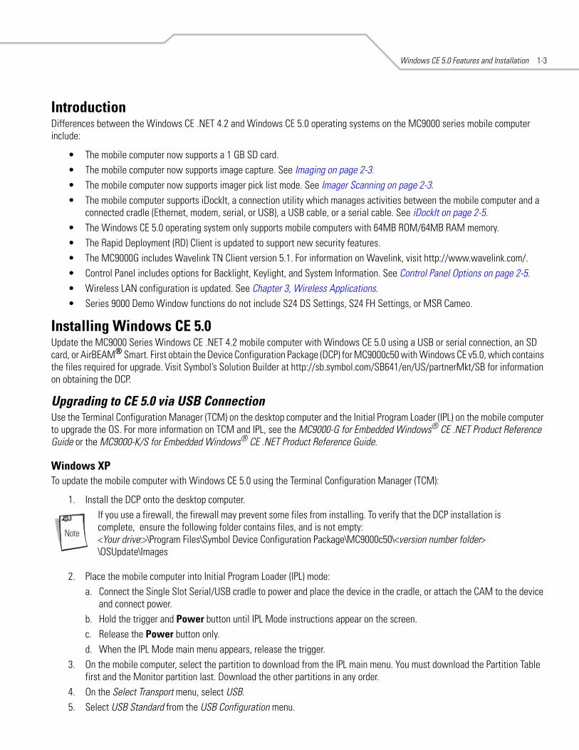
IntroductionDifferences between the Windows CE .NET 4.2 and Windows CE 5.0 operating systems on the MC9000 series mobile computer include:
• The mobile computer now supports a 1 GB SD card.• The mobile computer now supports image capture. See Imaging on page 2-3.• The mobile computer now supports imager pick list mode. See Imager Scanning on page 2-3.• The mobile computer supports iDockIt, a connection utility which manages activities between the mobile computer and a
connected cradle (Ethernet, modem, serial, or USB), a USB cable, or a serial cable. See iDockIt on page 2-5.• The Windows CE 5.0 operating system only supports mobile computers with 64MB ROM/64MB RAM memory.• The Rapid Deployment (RD) Client is updated to support new security features.• The MC9000G includes Wavelink TN Client version 5.1. For information on Wavelink, visit http://www.wavelink.com/. • Control Panel includes options for Backlight, Keylight, and System Information. See Control Panel Options on page 2-5.• Wireless LAN configuration is updated. See Chapter 3, Wireless Applications.• Series 9000 Demo Window functions do not include S24 DS Settings, S24 FH Settings, or MSR Cameo.
Installing Windows CE 5.0Update the MC9000 Series Windows CE .NET 4.2 mobile computer with Windows CE 5.0 using a USB or serial connection, an SD card, or AirBEAM® Smart. First obtain the Device Configuration Package (DCP) for MC9000c50 with Windows CE v5.0, which contains the files required for upgrade. Visit Symbol’s Solution Builder at http://sb.symbol.com/SB641/en/US/partnerMkt/SB for information on obtaining the DCP.
Upgrading to CE 5.0 via USB ConnectionUse the Terminal Configuration Manager (TCM) on the desktop computer and the Initial Program Loader (IPL) on the mobile computer to upgrade the OS. For more information on TCM and IPL, see the MC9000-G for Embedded Windows® CE .NET Product Reference Guide or the MC9000-K/S for Embedded Windows® CE .NET Product Reference Guide.
Windows XPTo update the mobile computer with Windows CE 5.0 using the Terminal Configuration Manager (TCM):
1. Install the DCP onto the desktop computer. If you use a firewall, the firewall may prevent some files from installing. To verify that the DCP installation is complete, ensure the following folder contains files, and is not empty:<Your drive:>\Program Files\Symbol Device Configuration Package\MC9000c50\<version number folder> \OSUpdate\Images
2. Place the mobile computer into Initial Program Loader (IPL) mode:a. Connect the Single Slot Serial/USB cradle to power and place the device in the cradle, or attach the CAM to the device
and connect power.b. Hold the trigger and Power button until IPL Mode instructions appear on the screen.c. Release the Power button only.d. When the IPL Mode main menu appears, release the trigger.
3. On the mobile computer, select the partition to download from the IPL main menu. You must download the Partition Table first and the Monitor partition last. Download the other partitions in any order.
4. On the Select Transport menu, select USB. 5. Select USB Standard from the USB Configuration menu.

MC9000 Series Addendum for Embedded Windows CE 5.01-4
6. On the Download File menu, select Download.7. Connect the mobile computer to the desktop computer via USB cable using the cradle or CAM. The desktop computer
displays the New Hardware Found installation wizard.8. On the desktop computer, select Install from a list or specific location, and click Next.9. Select the Include this location in the search checkbox, and click Next.10. On the warning window that appears, click Continue Anyway.11. Click Finish.12. Open TCM on the desktop computer. Select Start - Programs - Symbol Device Configuration Packages - MC9000c50 - TCM.13. Select File - Load Terminal.14. On the Load Terminal window, select USB from the Comm Port drop-down list. 15. Click the ... button.16. In the Files to Load window, select the file(s) specified in IPL in Step 3, then click Open.17. Click Download.18. Repeat steps 3-6 and 13-15 for the remaining partitions.19. After downloading all required partitions, if the mobile computer does not automatically reset, select System Reset on the
IPL main menu on the mobile computer.
Windows 2000To update the mobile computer with Windows CE 5.0 using the Terminal Configuration Manager (TCM):
1. Install the DCP onto the desktop computer.If you use a firewall, the firewall may prevent some files from installing. To verify that the DCP installation is complete, ensure the following folder contains files, and is not empty:<Your drive:>\Program Files\Symbol Device Configuration Package\MC9000c50\<version number folder> \OSUpdate\Images
2. Place the mobile computer into Initial Program Loader (IPL) mode:a. Connect the Single Slot Serial/USB cradle to power and place the device in the cradle, or attach the CAM to the device
and connect power.b. Hold the trigger and Power button until IPL Mode instructions appear on the screen.c. Release the Power button only.d. When the IPL Mode main menu appears, release the trigger.
3. On the mobile computer, select the partition to download from the IPL main menu. You must download the Partition Table first and the Monitor partition last. Download the other partitions in any order.
4. On the Select Transport menu, select USB.5. Select USB Standard from the USB Configuration menu.6. On the Download File menu, select Download.7. Connect the mobile computer to the desktop computer via USB cable using the cradle or CAM. The desktop computer
displays the New Hardware Found installation wizard.8. On the desktop computer, select Search for a suitable driver for my device (recommended), and click Next.9. Select the Specify a location checkbox, and click Next.10. Click OK to accept the path that appears indicating the location of the driver files.11. Click Next.
Windows CE 5.0 Features and Installation 1-5
12. Click Finish.13. Open TCM. Select Start - Programs - Symbol Device Configuration Packages - MC9000c50 - TCM.14. Select File - Load Terminal.15. On the Load Terminal window, select USB from the Comm Port drop-down list.16. Click the ... button.17. In the Files to Load window, select the file(s) specified in IPL in Step 3, then click Open.18. Click Download.19. Repeat steps 3-6 and 13-16 for the remaining partitions.20. After downloading all required partitions, if the mobile computer does not automatically reset, select System Reset on the
IPL main menu on the mobile computer.
Upgrading to CE 5.0 via Serial ConnectionUse the Terminal Configuration Manager (TCM) on the desktop computer and the Initial Program Loader (IPL) on the mobile computer to upgrade the OS. For more information on TCM and IPL, see the MC9000-G for Embedded Windows® CE .NET Product Reference Guide or the MC9000-K/S for Embedded Windows® CE .NET Product Reference Guide.
Upgrading the OS via USB is significantly faster than via serial connection.
1. Install the DCP onto the desktop computer.If you use a firewall, the firewall may prevent some files from installing. To verify that the DCP installation is complete, ensure the following folder contains files, and is not empty:<Your drive:>\Program Files\Symbol Device Configuration Package\MC9000c50\<version number folder> \OSUpdate\Images
2. Place the mobile computer into Initial Program Loader (IPL) mode:a. Connect the Single Slot Serial/USB cradle to power and place the device in the cradle, or attach the CAM to the device
and connect power.b. Hold the trigger and Power button until IPL Mode instructions appear on the screen.c. Release the Power button only.d. When the IPL Mode main menu appears, release the trigger.
3. On the mobile computer, select the partition to download from the IPL main menu. You must download the Partition Table first and the Monitor partition last. Download the other partitions in any order.
4. On the Select Transport menu, select Serial. 5. Select the baud rate from the Select Baud Rate menu.6. On the Download File menu, select Download.7. Connect the mobile computer to the desktop computer via serial cable using the cradle or CAM. 8. Open TCM on the desktop computer. Select Start - Programs - Symbol Device Configuration Packages - MC9000c50 - TCM.9. Select File - Load Terminal.10. On the Load Terminal window, select the appropriate serial COM port from the Comm Port drop-down list. Also select the
baud rate from the Baud Rate drop-down list.11. Click the ... button.12. In the Files to Load window, select the file(s) specified in IPL in Step 3, then click Open.

MC9000 Series Addendum for Embedded Windows CE 5.01-6
13. Click Download.14. Repeat steps 3-6 and 9-11 for the remaining partitions.15. After downloading all required partitions, select System Reset on the IPL main menu on the mobile computer.
Upgrading to CE 5.0 via SD CardTo upgrade using a Secure Digital (SD) card:
1. Install the DCP onto the desktop computer.If you use a firewall, the firewall may prevent some files from installing. To verify that the DCP installation is complete, ensure the following folder contains files, and is not empty:<Your drive:>\Program Files\Symbol Device Configuration Package\MC9000c50\<version number folder> \OSUpdate\Images
2. Insert an SD card with at least 16 MB of storage into the mobile computer. Refer to the MC9000-G Product Reference Guide for Embedded Windows® CE .NET or the MC9000-K/S for Embedded Windows® CE .NET Product Reference Guide for instructions.
3. Connect the mobile computer to power and to the desktop computer via a serial or USB cable using the Single Slot Serial/USB cradle or CAM, and set up a partnership between the two computers using ActiveSync. Refer to the MC9000-G Product Reference Guide for Embedded Windows® CE .NET or the MC9000-K/S for Embedded Windows® CE .NET Product Reference Guide for instructions.
4. In the ActiveSync window on the desktop computer, select Explore.5. On the drive in which you installed the DCP (typically C:), navigate to the directory:
\Program Files\Symbol Device Configuration Packages\MC9000c50\V1.0\6. Copy the OSUpdate folder into the My Device\Storage Card\ folder on the mobile computer.7. On the mobile computer, tap Start - Programs - Windows Explorer.8. Double-tap the Storage Card folder.9. For a mobile computer with a color display, double-tap the 9000c50enColor_SD.LNK file.
For a mobile computer with a monochrome display, double-tap the 9000c50enMono_SD.LNK file.10. After the update completes and the mobile computer reboots, remove the SD card.
Upgrading to CE 5.0 via AirBEAM SmartTo upgrade using AirBEAM Smart, use the files in the OSUpdateFiles folder in the directory C:\Program Files\Symbol Device Configuration Packages\MC9000c50\V1.0\. See the MC9000-G Product Reference Guide for Embedded Windows® CE .NET or the MC9000-K/S for Embedded Windows® CE .NET Product Reference Guide for instructions on using AirBEAM Smart.
Downgrading to Windows CE .NET 4.2To downgrade a Windows CE 5.0 mobile computer to the Windows CE .NET 4.2 operating system, use a USB or serial connection. First obtain the Microsoft Windows CE.Net v4.2 Upgrade for MC 90xx-G Terminals from devzone.symbol.com.
You cannot use AirBEAM Smart or an SD card to downgrade the mobile computer.
Follow the procedures in Upgrading to CE 5.0 via USB Connection on page 1-3 or Upgrading to CE 5.0 via Serial Connection on page 1-5 to downgrade to Windows CE .NET 4.2, using the package downloaded from the devzone.

New Features
Contents
Introduction . . . . . . . . . . . . . . . . . . . . . . . . . . . . . . . . . . . . . . . . . . . . . . . . . . . . . . . . . . . . . . . . . . . . . . . . . . . . 2-3Imaging. . . . . . . . . . . . . . . . . . . . . . . . . . . . . . . . . . . . . . . . . . . . . . . . . . . . . . . . . . . . . . . . . . . . . . . . . . . . . . . . . 2-3
Operational Modes. . . . . . . . . . . . . . . . . . . . . . . . . . . . . . . . . . . . . . . . . . . . . . . . . . . . . . . . . . . . . . . . . . . . 2-3Imager Scanning. . . . . . . . . . . . . . . . . . . . . . . . . . . . . . . . . . . . . . . . . . . . . . . . . . . . . . . . . . . . . . . . . . . . . . 2-3
iDockIt. . . . . . . . . . . . . . . . . . . . . . . . . . . . . . . . . . . . . . . . . . . . . . . . . . . . . . . . . . . . . . . . . . . . . . . . . . . . . . . . . . 2-5Control Panel Options. . . . . . . . . . . . . . . . . . . . . . . . . . . . . . . . . . . . . . . . . . . . . . . . . . . . . . . . . . . . . . . . . . . . . . 2-5
Backlight. . . . . . . . . . . . . . . . . . . . . . . . . . . . . . . . . . . . . . . . . . . . . . . . . . . . . . . . . . . . . . . . . . . . . . . . . . . . 2-5Keylight. . . . . . . . . . . . . . . . . . . . . . . . . . . . . . . . . . . . . . . . . . . . . . . . . . . . . . . . . . . . . . . . . . . . . . . . . . . . . 2-7System Information . . . . . . . . . . . . . . . . . . . . . . . . . . . . . . . . . . . . . . . . . . . . . . . . . . . . . . . . . . . . . . . . . . . 2-9

MC9000 Series Addendum for Embedded Windows CE 5.02-2

New Features 2-3
IntroductionThis chapter describes the additional features the MC9000 with Windows CE 5.0 supports.
ImagingMobile computers with an integrated imager have the following features:
• Omnidirectional reading of a variety of bar code symbologies, including the most popular linear, postal, PDF417, and 2D matrix code types.
• The ability to capture and download images to a host for a variety of imaging applications.• Advanced intuitive laser aiming for easy point-and-shoot operation.
The imager uses digital camera technology to take a digital picture of a bar code, stores the resulting image in its memory, and executes state-of-the-art software decoding algorithms to extract the data from the image.
Operational ModesMobile computers with an integrated imager support three modes of operation, listed below. Activate each mode by pulling the trigger or pressing the Scan button.
• Decode Mode: In this mode, the mobile computer attempts to locate and decode enabled bar codes within its field of view. The imager remains in this mode as long as you hold the trigger, or until it decodes a bar code.
• Pick List Mode: This mode allows you to selectively decode a bar code when more than one bar code is in the mobile computer’s field of view. To accomplish this, move the aiming crosshair over the required bar code to decode only this bar code. This feature is ideal for pick lists containing multiple bar codes and manufacturing or transport labels containing more than one bar code type (either 1D or 2D).
• Image Capture Mode: Use this mode to capture an image within the mobile computer’s field of view. This is useful for capturing signatures or images of items like damaged boxes.
Imager Scanning1. Ensure that a scan-enabled application is loaded on the mobile computer.2. Aim the scan window at the bar code.3. Press the scan button. The red laser aiming pattern turns on to assist in aiming. Ensure the bar code is within the area formed
by the brackets in the aiming pattern. The scan LED lights red to indicate that scanning is in process, then lights green and a beep sounds, by default, to indicate the bar code was decoded successfully. Note that when the mobile computer is in Pick List Mode, the imager does not decode the bar code until the crosshair touches the bar code.
MC9000 Series Addendum for Embedded Windows CE 5.02-4
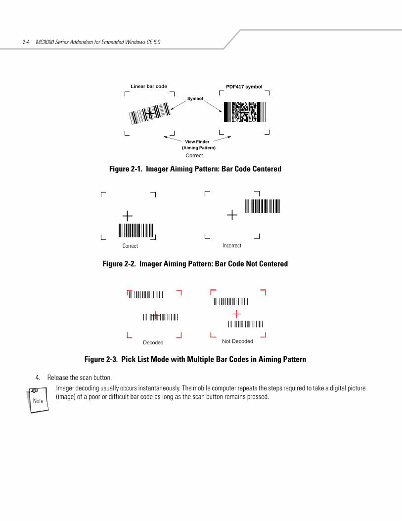
Figure 2-1. Imager Aiming Pattern: Bar Code Centered
Figure 2-2. Imager Aiming Pattern: Bar Code Not Centered
Figure 2-3. Pick List Mode with Multiple Bar Codes in Aiming Pattern
4. Release the scan button.Imager decoding usually occurs instantaneously. The mobile computer repeats the steps required to take a digital picture (image) of a poor or difficult bar code as long as the scan button remains pressed.
Linear bar code PDF417 symbol
Symbol
View Finder(Aiming Pattern)
Correct
Correct Incorrect

New Features 2-5
iDockItiDockIt is a connection utility which manages activities between the mobile computer and a connected cradle (Ethernet, modem, serial, or USB), a USB cable, or a serial cable. For more information on the utility, see the documentation provided with iDockIt.
iDockIt features:
• The ability to manage multiple cradle profiles. iDockIt auto-detects the cradle communication type and behaves accordingly.• Integrated modem capabilities using TAPI interface.• Runs as a tray application, and always runs in the background.• uConnect software, allowing automatic multi-dock USB synchronization.• The ability to configure settings within the application.• Options to change parameters upon docking (with or without settings time-out).• The ability to force synchronization events.• The ability to disable WLAN connection on the device to ensure synchronization is performed via dock.• Management of multiple connection types without losing settings.
Control Panel OptionsThe Control Panel now includes options for Backlight, Keylight, and System Information.
BacklightUse the Backlight tabs to adjust backlight brightness and power settings.
Battery PowerTo set the backlight settings when using battery power:
1. Select Start - Settings - Control Panel, and double-tap the Backlight icon.
Figure 2-4. Backlight Settings Window - Battery Power Tab
2. Select the Disable backlight if device is not used for check box to turn off the backlight when the device is not used for a certain period of time. Select this period of time from the drop-down list. Available times are 10 seconds, 30 seconds, 1 minute, 2 minutes, 3 minutes, 4 minutes, and 5 minutes.
3. Select the Enable backlight when a button is pressed or the screen is tapped check box to turn on the backlight when one of these events occur.
4. Tap ok.

MC9000 Series Addendum for Embedded Windows CE 5.02-6
External PowerTo set the backlight settings when using external AC power:
1. Select Start - Settings - Control Panel, double-tap the Backlight icon.2. Tap the External Power tab.
Figure 2-5. Backlight Settings Window - External Power Tab
3. Select the Disable backlight if device is not used for check box to turn off the backlight when the device is not used for a certain period of time. Select this period of time from the drop-down list. Available times are 1 through 10 minutes in 1-minute intervals.
4. Select the Enable backlight when a button is pressed or the screen is tapped check box to turn on the backlight when one of these events occur.
5. Tap ok.
BrightnessTo set a brightness level for the backlight:
1. Select Start - Settings - Control Panel, double-tap the Backlight icon.2. Tap the Brightness tab.
Figure 2-6. Backlight Settings Window - Brightness Tab
3. Select the Disable backlight check box to turn off the backlight completely.4. If the Disable backlight check box is unchecked, use the slider to adjust screen brightness. 5. Tap ok.

New Features 2-7
KeylightUse the Keylight tabs to adjust the brightness and power settings of the keypad light.
Battery PowerTo set the keypad light settings when using battery power:
1. Select Start - Settings - Control Panel, and double-tap the Keylight icon.
Figure 2-7. Keylight Settings Window - Battery Power Tab
2. Select the Disable keylight if device is not used for check box to turn off the keypad light when the device is not used for a certain period of time. Select this period of time from the drop-down list. Available times are 10 seconds, 30 seconds, 1 minute, 2 minutes, 3 minutes, 4 minutes, and 5 minutes.
3. Select the Enable keylight when a button is pressed or the screen is tapped check box to turn on the keypad light when one of these events occur.
4. Tap ok.
External PowerTo set the keypad light settings when using external AC power:
1. Select Start - Settings - Control Panel, double-tap the Keylight icon.2. Tap the External Power tab.
Figure 2-8. Keylight Settings Window - External Power Tab

MC9000 Series Addendum for Embedded Windows CE 5.02-8
3. Select the Disable keylight if device is not used for check box to turn off the keypad light when the device is not used for a certain period of time. Select this period of time from the drop-down list. Available times are 1 through 10 minutes in 1-minute intervals.
4. Select the Enable keylight when a button is pressed or the screen is tapped check box to turn on the keypad light when one of these events occur.
5. Tap ok.
AdvancedTo enable or disable the keypad light and backlight tracking:
1. Select Start - Settings - Control Panel, double-tap the Keylight icon.2. Tap the Advanced tab.
Figure 2-9. Keylight Settings Window - Advanced Tab
3. Select the Disable keylight check box to turn off the keypad light completely.4. Select the Track Backlight check box to turn the keylight on and off with the backlight, i.e., when the backlight is on, the
keylight is on, and when the backlight is off, keylight is off.5. Tap ok.

New Features 2-9
System InformationUse the System Information tabs to view information on the mobile computer’s system components.
System TabThe System tab displays the versions of the operating system, applications, and partitions running on the mobile computer.
Select Start - Settings - Control Panel, and double-tap the System Info icon.
Figure 2-10. System Information Window - System Tab
Display TabThe Display tab displays information for the mobile computer’s screen.
Select Start - Settings - Control Panel, double-tap the System Info icon, then tap the Display tab.
Figure 2-11. System Information Window - Display Tab

MC9000 Series Addendum for Embedded Windows CE 5.02-10
Misc TabThe Misc tab displays the size and speed for various mobile computer components.
Select Start - Settings - Control Panel, double-tap the System Info icon, then tap the Misc tab.
Figure 2-12. System Information Window - Miscellaneous Tab

Wireless Applications
ContentsIntroduction . . . . . . . . . . . . . . . . . . . . . . . . . . . . . . . . . . . . . . . . . . . . . . . . . . . . . . . . . . . . . . . . . . . . . . . . . . . . 3-3Signal Strength Icon. . . . . . . . . . . . . . . . . . . . . . . . . . . . . . . . . . . . . . . . . . . . . . . . . . . . . . . . . . . . . . . . . . . . . . . 3-3Turning the WLAN Radio On and Off. . . . . . . . . . . . . . . . . . . . . . . . . . . . . . . . . . . . . . . . . . . . . . . . . . . . . . . . . . 3-4Find WLANs Application . . . . . . . . . . . . . . . . . . . . . . . . . . . . . . . . . . . . . . . . . . . . . . . . . . . . . . . . . . . . . . . . . . . 3-5Profile Editor Wizard . . . . . . . . . . . . . . . . . . . . . . . . . . . . . . . . . . . . . . . . . . . . . . . . . . . . . . . . . . . . . . . . . . . . . . 3-6
Profile ID. . . . . . . . . . . . . . . . . . . . . . . . . . . . . . . . . . . . . . . . . . . . . . . . . . . . . . . . . . . . . . . . . . . . . . . . . . . . 3-6Operating Mode . . . . . . . . . . . . . . . . . . . . . . . . . . . . . . . . . . . . . . . . . . . . . . . . . . . . . . . . . . . . . . . . . . . . . . 3-7Ad-Hoc . . . . . . . . . . . . . . . . . . . . . . . . . . . . . . . . . . . . . . . . . . . . . . . . . . . . . . . . . . . . . . . . . . . . . . . . . . . . . 3-8Authentication . . . . . . . . . . . . . . . . . . . . . . . . . . . . . . . . . . . . . . . . . . . . . . . . . . . . . . . . . . . . . . . . . . . . . . . 3-8Tunneled Authentication . . . . . . . . . . . . . . . . . . . . . . . . . . . . . . . . . . . . . . . . . . . . . . . . . . . . . . . . . . . . . . . 3-9User Certificate Selection . . . . . . . . . . . . . . . . . . . . . . . . . . . . . . . . . . . . . . . . . . . . . . . . . . . . . . . . . . . . . 3-11Server Certificate Selection . . . . . . . . . . . . . . . . . . . . . . . . . . . . . . . . . . . . . . . . . . . . . . . . . . . . . . . . . . . . 3-12Credential Cache Options . . . . . . . . . . . . . . . . . . . . . . . . . . . . . . . . . . . . . . . . . . . . . . . . . . . . . . . . . . . . . 3-13Password . . . . . . . . . . . . . . . . . . . . . . . . . . . . . . . . . . . . . . . . . . . . . . . . . . . . . . . . . . . . . . . . . . . . . . . . . . 3-15Advanced Identity. . . . . . . . . . . . . . . . . . . . . . . . . . . . . . . . . . . . . . . . . . . . . . . . . . . . . . . . . . . . . . . . . . . . 3-16Encryption. . . . . . . . . . . . . . . . . . . . . . . . . . . . . . . . . . . . . . . . . . . . . . . . . . . . . . . . . . . . . . . . . . . . . . . . . . 3-16IP Mode . . . . . . . . . . . . . . . . . . . . . . . . . . . . . . . . . . . . . . . . . . . . . . . . . . . . . . . . . . . . . . . . . . . . . . . . . . . 3-19IP Address Entry . . . . . . . . . . . . . . . . . . . . . . . . . . . . . . . . . . . . . . . . . . . . . . . . . . . . . . . . . . . . . . . . . . . . . 3-19Transmit Power . . . . . . . . . . . . . . . . . . . . . . . . . . . . . . . . . . . . . . . . . . . . . . . . . . . . . . . . . . . . . . . . . . . . . 3-20Battery Usage. . . . . . . . . . . . . . . . . . . . . . . . . . . . . . . . . . . . . . . . . . . . . . . . . . . . . . . . . . . . . . . . . . . . . . .3-21Manage Profiles Application . . . . . . . . . . . . . . . . . . . . . . . . . . . . . . . . . . . . . . . . . . . . . . . . . . . . . . . . . . . 3-22
Wireless Status Application . . . . . . . . . . . . . . . . . . . . . . . . . . . . . . . . . . . . . . . . . . . . . . . . . . . . . . . . . . . . . . . 3-26Signal Strength Window . . . . . . . . . . . . . . . . . . . . . . . . . . . . . . . . . . . . . . . . . . . . . . . . . . . . . . . . . . . . . . 3-27Current Profile Window . . . . . . . . . . . . . . . . . . . . . . . . . . . . . . . . . . . . . . . . . . . . . . . . . . . . . . . . . . . . . . . 3-29IPv4 Status Window. . . . . . . . . . . . . . . . . . . . . . . . . . . . . . . . . . . . . . . . . . . . . . . . . . . . . . . . . . . . . . . . . . 3-30

MC9000 Series Addendum for Embedded Windows CE 5.03-2
Wireless Log Window . . . . . . . . . . . . . . . . . . . . . . . . . . . . . . . . . . . . . . . . . . . . . . . . . . . . . . . . . . . . . . . .3-31Versions Window . . . . . . . . . . . . . . . . . . . . . . . . . . . . . . . . . . . . . . . . . . . . . . . . . . . . . . . . . . . . . . . . . . . .3-32
Wireless Diagnostics Application . . . . . . . . . . . . . . . . . . . . . . . . . . . . . . . . . . . . . . . . . . . . . . . . . . . . . . . . . . .3-33ICMP Ping Window. . . . . . . . . . . . . . . . . . . . . . . . . . . . . . . . . . . . . . . . . . . . . . . . . . . . . . . . . . . . . . . . . . .3-34Trace Route Window . . . . . . . . . . . . . . . . . . . . . . . . . . . . . . . . . . . . . . . . . . . . . . . . . . . . . . . . . . . . . . . . .3-35Known APs Window. . . . . . . . . . . . . . . . . . . . . . . . . . . . . . . . . . . . . . . . . . . . . . . . . . . . . . . . . . . . . . . . . .3-36
Options . . . . . . . . . . . . . . . . . . . . . . . . . . . . . . . . . . . . . . . . . . . . . . . . . . . . . . . . . . . . . . . . . . . . . . . . . . . . . . . .3-37Operating Mode Filtering . . . . . . . . . . . . . . . . . . . . . . . . . . . . . . . . . . . . . . . . . . . . . . . . . . . . . . . . . . . . . .3-37Regulatory Options . . . . . . . . . . . . . . . . . . . . . . . . . . . . . . . . . . . . . . . . . . . . . . . . . . . . . . . . . . . . . . . . . . .3-38Band Selection . . . . . . . . . . . . . . . . . . . . . . . . . . . . . . . . . . . . . . . . . . . . . . . . . . . . . . . . . . . . . . . . . . . . . .3-38System Options. . . . . . . . . . . . . . . . . . . . . . . . . . . . . . . . . . . . . . . . . . . . . . . . . . . . . . . . . . . . . . . . . . . . . .3-39Change Password Dialog Box. . . . . . . . . . . . . . . . . . . . . . . . . . . . . . . . . . . . . . . . . . . . . . . . . . . . . . . . . . .3-40Export . . . . . . . . . . . . . . . . . . . . . . . . . . . . . . . . . . . . . . . . . . . . . . . . . . . . . . . . . . . . . . . . . . . . . . . . . . . . .3-40
Cold Boot Persistence. . . . . . . . . . . . . . . . . . . . . . . . . . . . . . . . . . . . . . . . . . . . . . . . . . . . . . . . . . . . . . . . . . . . .3-42Registry Settings. . . . . . . . . . . . . . . . . . . . . . . . . . . . . . . . . . . . . . . . . . . . . . . . . . . . . . . . . . . . . . . . . . . . . . . . .3-42Log On/Off Application . . . . . . . . . . . . . . . . . . . . . . . . . . . . . . . . . . . . . . . . . . . . . . . . . . . . . . . . . . . . . . . . . . . .3-43
User Already Logged In . . . . . . . . . . . . . . . . . . . . . . . . . . . . . . . . . . . . . . . . . . . . . . . . . . . . . . . . . . . . . . .3-43No User Logged In . . . . . . . . . . . . . . . . . . . . . . . . . . . . . . . . . . . . . . . . . . . . . . . . . . . . . . . . . . . . . . . . . . .3-43

Wireless Applications 3-3
IntroductionWireless LANs allow mobile computers to communicate wirelessly and to send captured data to a host device in real time. Before a mobile computer can be used on a WLAN, the facility must be set up with the required hardware to run the wireless LAN and the mobile computer must be properly configured. Refer to the documentation that came with the Access Points (APs) for instructions on setting up the hardware.
To configure the mobile computer, a set of wireless applications provide the user with the tools to configure and test the wireless radio embedded the mobile computer. The following wireless applications are available on the task tray from the Wireless Application menu:
• Wireless Status• Wireless Diagnostics• Find WLANs• Manage Profiles• Options• Log On/Off• Enable/Disable Radio• Cancel Menu• Exit.
Tap the Signal Strength icon to display the Wireless Application menu.
Figure 3-1. Wireless Applications Menu
Signal Strength IconThe Signal Strength icon in the task tray indicates the mobile computer’s wireless signal strength as follows:
Table 3-1. Wireless Applications Icons, Signal Strength Descriptions
Icon Status Action
Excellent signal strength Wireless LAN network is ready to use.
Very good signal strength Wireless LAN network is ready to use.
Good signal strength Wireless LAN network is ready to use.
Signal Strength Icon

MC9000 Series Addendum for Embedded Windows CE 5.03-4
Turning the WLAN Radio On and OffTo turn the WLAN radio off tap the Signal Strength icon and select Disable Radio.
Figure 3-2. Disable Radio
To turn the WLAN radio on tap the Signal Strength icon and select Enable Radio.
Figure 3-3. Enable Radio
Fair signal strength Wireless LAN network is ready to use. Notify the network administrator that the signal strength is only “Fair”.
Poor signal strength Wireless LAN network is ready to use. Performance may not be optimum. Notify the network administrator that the signal strength is “Poor”.
Out-of-network range (not associated) No wireless LAN network connection. Notify the network administrator.
No wireless LAN network card detected. No wireless LAN network card detected or radio disabled. Notify the network administrator.
Table 3-1. Wireless Applications Icons, Signal Strength Descriptions (Continued)
Icon Status Action
Wireless Applications 3-5
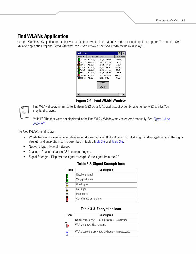
Find WLANs ApplicationUse the Find WLANs application to discover available networks in the vicinity of the user and mobile computer. To open the Find WLANs application, tap the Signal Strength icon - Find WLANs. The Find WLANs window displays.
Figure 3-4. Find WLAN Window
Find WLAN display is limited to 32 items (ESSIDs or MAC addresses). A combination of up to 32 ESSIDs/APs may be displayed.
Valid ESSIDs that were not displayed in the Find WLAN Window may be entered manually. See Figure 3-5 on page 3-6.
The Find WLANs list displays:
• WLAN Networks - Available wireless networks with an icon that indicates signal strength and encryption type. The signal strength and encryption icon is described in tables Table 3-2 and Table 3-3.
• Network Type - Type of network.• Channel - Channel that the AP is transmitting on.• Signal Strength - Displays the signal strength of the signal from the AP.
Table 3-2. Signal Strength IconIcon Description
Excellent signal
Very good signal
Good signal
Fair signal
Poor signal
Out of range or no signal
Table 3-3. Encryption IconIcon Description
No encryption WLAN is an infrastructure network.
WLAN is an Ad-Hoc network.
WLAN access is encrypted and requires a password.

MC9000 Series Addendum for Embedded Windows CE 5.03-6
Tap-and-hold on a WLAN network to launch a context sensitive menu. The menu provides two options: Connect and Refresh. Select Refresh to refresh the WLAN list. Wireless profiles may also be created from one of the listed networks by selecting a network from the list and then selecting Connect. Selecting Connect displays the Profile Editor Wizard. The wizard is initialized to set the values for the selected network. After the profile editing is completed, it automatically connects to the newly edited profile.
Profile Editor WizardThe Profile Editor Wizard displays when creating a new profile, or editing an existing profile. If editing a profile, the fields are populated with the current settings for that profile. If creating a new profile, the known information for that WLAN network are populated into the fields.
Navigate through the wizard using the Next and Back buttons. Tap X to quit, a notification box appears asking the user to confirm the quit. Tap No to return to the wizard or tap Yes to quit and return to the Manage Profiles window.
Profile IDThe Profile ID dialog box is the first dialog box in the Profile Editor Wizard. Use the Profile ID dialog box to input the fields for the profile name and the ESSID.
Figure 3-5. Profile ID Dialog Box
Two profiles with the same user friendly name are valid but not recommended.
Tap Next. The Operating Mode dialog box displays.
Table 3-4. Profile ID Fields
Field Description
Name Populated with the name and (WLAN) identifier of the network connection. Use the Name: field to enter a user friendly name of the mobile computer profile used to connect to either an AP or another networked computer. Example: The Public LAN.
ESSID Populated with the name and (WLAN) identifier of the network connection, or use the ESSID field to enter the name and (WLAN) identifier of a WLAN network connection that was not listed on the Find WLANs window.The ESSID is the 802.11 extended service set identifier. The ESSID is 32-character (maximum) string identifying the WLAN. The ESSID assigned to the mobile computer is required to match the AP ESSID for the mobile computer to communicate with the AP.

Wireless Applications 3-7
Operating ModeUse the Operating Mode dialog box to select the operating mode (Infrastructure or Ad-Hoc) and the country location.
Figure 3-6. Operating Mode Dialog Box
Tap Next. If Ad-Hoc mode was selected the Ad-Hoc dialog box displays. If Infrastructure mode was selected the Authentication dialog box displays. See Authentication on page 3-8 for instruction on setting up authentication.
Table 3-5. Operating Mode Fields
Field Description
Operating Mode Infrastructure: Select Infrastructure to enable the mobile computer to transmit and receive data with an AP. Infrastructure is the mobile computer default mode.Ad Hoc: Select Ad Hoc to enable the mobile computer to form its own local network where mobile computers communicate peer-to-peer without APs using a shared ESSID.
Country Country is used to determine if the profile is valid for the country of operation. The profile country must match the country in the options page or it must match the acquired country if 802.11d is enabled.Single Country Use:When the device is only to be used in a single country, set every profile country to Allow Any Country. In the Options - Regulatory dialog box (see Figure 3-47 on page 3-38), set the country to the specific country the device is to be used in, and deselect (uncheck) the Enable 802.11d option. This is the most common and the efficient configuration. It eliminates the initialization overhead associated with acquiring a country via 802.11d. Multiple Country Use:When the device may be used in more than one country, select (check) the Enable 802.11d option in the Regulatory Options dialog box (see Figure 3-47 on page 3-38). This eliminates the need for reprograming the country (in Options - Regulatory) each time a new country is entered. However, this only works if the infrastructure (i.e. APs) support 802.11d (some infrastructures do not support 802.11d, including some Cisco APs). When the Enable 802.11d option is selected, the Options - Regulatory - Country setting is not used. For a single profile that can be used in multiple countries, with infrastructure that supports 802.11d (including Symbol infrastructure), set the Profile Country to Allow Any Country. Under Options - Regulatory, select Enable 802.11d. The Options - Regulatory - Country setting is not used.For a single profile that can be used in multiple countries, but with infrastructure that does not support 802.11d, set the profile country to Allow Any Country, and de-select (uncheck) Enable 802.11d. In this case, the Options - Regulatory - Country setting must always be set to the country the device is currently in. This configuration option is the most efficient and may be chosen for use with any infrastructure. However, the Options - Regulatory - Country setting must be manually changed when a new country is entered.Note that using a single profile in multiple countries implies that there is a common ESSID to connect to in each country. This is less likely than having unique ESSIDs in each country, this requires unique profiles for each country.For additional efficiency when using multiple profiles that can be used in multiple countries, the country setting for each profile can be set to a specific country. If the current country (found via 802.11d or set by Options - Regulatory - Country when 802.11d is disabled) does not match the country set in a given profile, then that profile is disabled. This can make profile roaming occur faster. For example, if two profiles are created and configured for Japan, and two more profiles are created and configured for USA, then when in Japan only the first two profiles are active, and when in USA only the last two are active. If they had all been configured for Allow Any Country, then all four would always be active, making profile roaming less efficient.

MC9000 Series Addendum for Embedded Windows CE 5.03-8
Ad-HocUse the Ad-Hoc dialog box to select the necessary information to control Ad-Hoc mode. This dialog box does not display if Infrastructure mode is selected. To Select Ad-Hoc mode:
1. Select a channel number from the Channel drop-down list. The default is Channel 1 (2412 MHz).
Figure 3-7. Ad-Hoc Settings Dialog Box
2. Tap Next. The Authentication dialog box displays.
AuthenticationUse the Authentication dialog box to configure authentication. If Ad-Hoc mode is selected, the user can only select None because Ad-Hoc authentication is not supported. Table 3-6 lists the available authentication options.
Figure 3-8. Authentication Dialog Box
Select an authentication type from the drop-down list and tap Next. If PEAP or TTLS is selected, the Tunneled dialog box displays. If None, EAP TLS or LEAP is selected the Encryption dialog box displays. See Encryption on page 3-16 for encryption options.
Table 3-6. Authentication Options
Authentication Description
None Default setting when authentication is not required on the network.
EAP TLS Select this option to enable EAP TLS authentication. EAP TLS is an authentication scheme through IEEE 802.1x. It authenticates users and ensures only valid users can connect to the network. It also restricts unauthorized users from accessing transmitted information. EAP TLS achieves this through secure authentication certificates.
PEAP Select this option to enable PEAP authentication. This method uses a digital certificate to verify and authenticate a user's identity.
LEAP Select this option to enable LEAP authentication. LEAP is founded on mutual authentication. The AP and the mobile computer attempting to connect to it require authentication before access to the network is permitted.
TTLS Select this option to enable TTLS authentication.

Wireless Applications 3-9
Tunneled AuthenticationUse the Tunneled Authentication dialog box to select the tunneled authentication options. There are different selections available for PEAP or TTLS authentication. To select a tunneled authentication type
Figure 3-9. Tunneled Auth Dialog Box
1. Tap a tunneled authentication type from the drop-down list. 2. Select the User Certificate check box if a certificate is required. The TLS tunnel type requires a user certificate, so the check
box is automatically selected.3. Tap Next. The Installed User Certs dialog box appears.
Table 3-7 lists the PEAP tunneled authentication options.
Table 3-7. PEAP Tunneled Authentication Options
PEAP Tunneled Authentication Description
MS CHAP v2 Microsoft Challenge Handshake Authentication Protocol version 2 (MS CHAP v2) is a password-based, challenge-response, mutual authentication protocol that uses the industry-standard Message Digest 4 (MD4) and Data Encryption Standard (DES) algorithms to encrypt responses. The authenticating server challenges the access client and the access client challenges the authenticating server. If either challenge is not correctly answered, the connection is rejected. MS CHAP v2 was originally designed by Microsoft as a PPP authentication protocol to provide better protection for dial-up and virtual private network (VPN) connections. With Windows XP SP1, Windows XP SP2, Windows Server 2003, and Windows 2000 SP4, MS CHAP v2 is also an EAP type.
TLS EAP TLS is used during the phase 2 of the authentication process. This method uses a user certificate to authenticate.
MC9000 Series Addendum for Embedded Windows CE 5.03-10
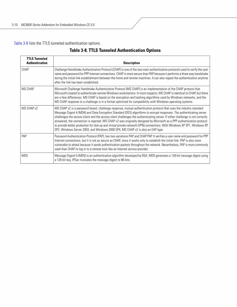
Table 3-8 lists the TTLS tunneled authentication options.
Table 3-8. TTLS Tunneled Authentication Options
TTLS Tunneled Authentication Description
CHAP Challenge Handshake Authentication Protocol (CHAP) is one of the two main authentication protocols used to verify the user name and password for PPP Internet connections. CHAP is more secure than PAP because it performs a three way handshake during the initial link establishment between the home and remote machines. It can also repeat the authentication anytime after the link has been established.
MS CHAP Microsoft Challenge Handshake Authentication Protocol (MS CHAP) is an implementation of the CHAP protocol that Microsoft created to authenticate remote Windows workstations. In most respects, MS CHAP is identical to CHAP, but there are a few differences. MS CHAP is based on the encryption and hashing algorithms used by Windows networks, and the MS CHAP response to a challenge is in a format optimized for compatibility with Windows operating systems.
MS CHAP v2 MS CHAP v2 is a password based, challenge response, mutual authentication protocol that uses the industry standard Message Digest 4 (MD4) and Data Encryption Standard (DES) algorithms to encrypt responses. The authenticating server challenges the access client and the access client challenges the authenticating server. If either challenge is not correctly answered, the connection is rejected. MS CHAP v2 was originally designed by Microsoft as a PPP authentication protocol to provide better protection for dial-up and virtual private network (VPN) connections. With Windows XP SP1, Windows XP SP2, Windows Server 2003, and Windows 2000 SP4, MS CHAP v2 is also an EAP type.
PAP Password Authentication Protocol (PAP), has two variations PAP and CHAP PAP. It verifies a user name and password for PPP Internet connections, but it is not as secure as CHAP, since it works only to establish the initial link. PAP is also more vulnerable to attack because it sends authentication packets throughout the network. Nevertheless, PAP is more commonly used than CHAP to log in to a remote host like an Internet service provider.
MD5 Message Digest-5 (MD5) is an authentication algorithm developed by RSA. MD5 generates a 128-bit message digest using a 128-bit key, IPSec truncates the message digest to 96 bits.
Wireless Applications 3-11
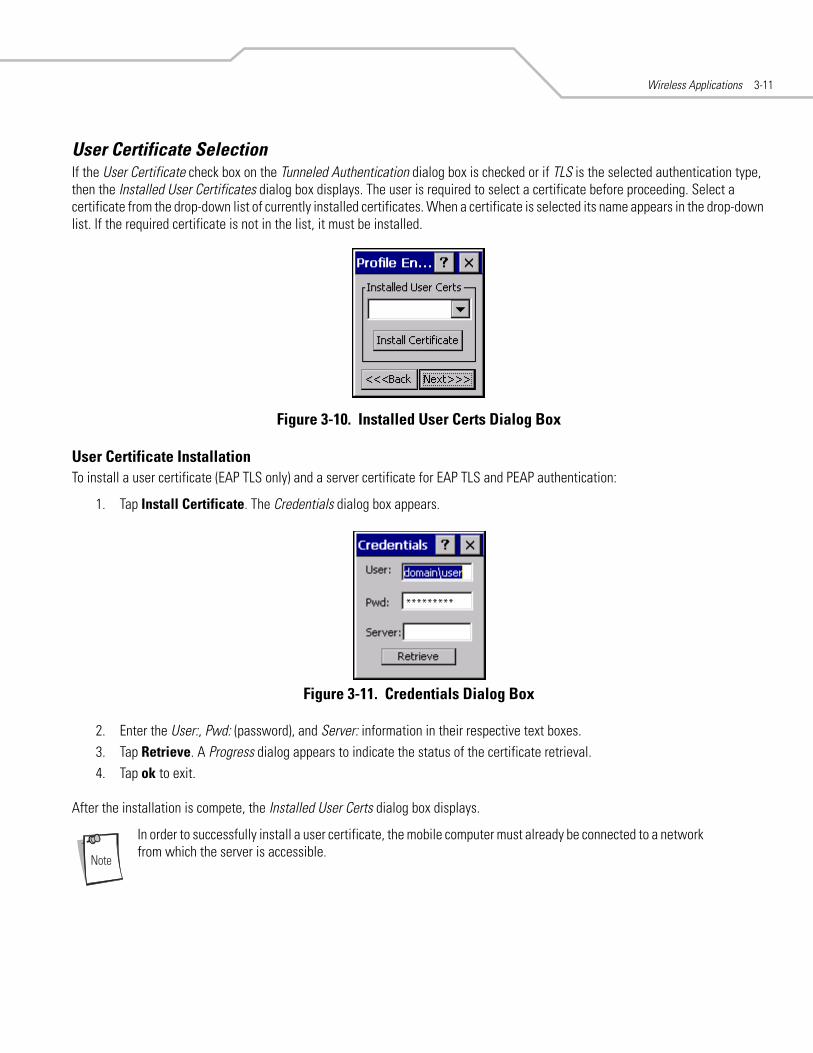
User Certificate SelectionIf the User Certificate check box on the Tunneled Authentication dialog box is checked or if TLS is the selected authentication type, then the Installed User Certificates dialog box displays. The user is required to select a certificate before proceeding. Select a certificate from the drop-down list of currently installed certificates. When a certificate is selected its name appears in the drop-down list. If the required certificate is not in the list, it must be installed.
Figure 3-10. Installed User Certs Dialog Box
User Certificate InstallationTo install a user certificate (EAP TLS only) and a server certificate for EAP TLS and PEAP authentication:
1. Tap Install Certificate. The Credentials dialog box appears.
Figure 3-11. Credentials Dialog Box
2. Enter the User:, Pwd: (password), and Server: information in their respective text boxes.3. Tap Retrieve. A Progress dialog appears to indicate the status of the certificate retrieval.4. Tap ok to exit.
After the installation is compete, the Installed User Certs dialog box displays.
In order to successfully install a user certificate, the mobile computer must already be connected to a network from which the server is accessible.
*********

MC9000 Series Addendum for Embedded Windows CE 5.03-12
Server Certificate SelectionIf the Validate Server Cert check box is checked, a server certificate is required. The wizard displays the Installed Server Certs dialog box and a certificate must be selected before proceeding. An hour glass may be displayed as the wizard populates the existing certificate list. If the required certificate is not listed, then it must be installed.
To select a certificate:
1. Tap the down arrow on the drop-down list to display the list of currently installed certificates. 2. Tap a certificate to select and its name appears in the drop-down list.3. Tap the Install Certificate button to install a certificate.
Figure 3-12. Installed Server Certs Dialog Box
A dialog is displayed that lists the currently loaded certificate files. This dialog lists the certificate files found in the default directory (\Application\FusionApps\Certs) with the default extension.
Figure 3-13. Browse Server Certificates
Wireless Applications 3-13
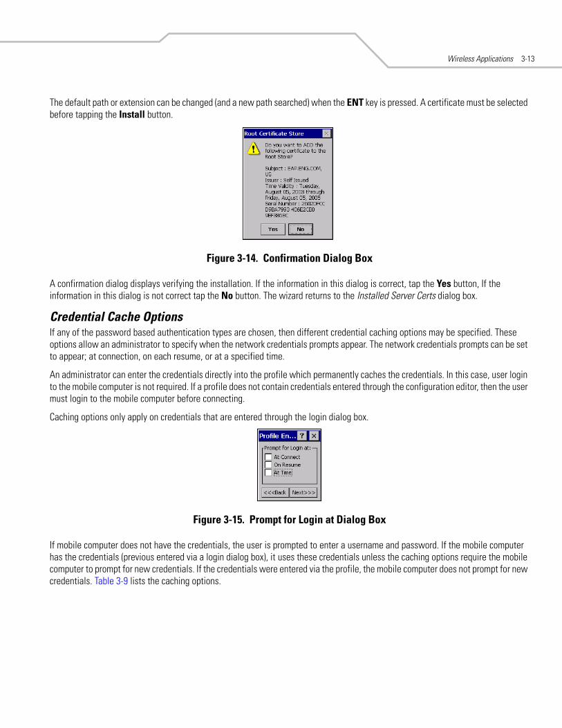
The default path or extension can be changed (and a new path searched) when the ENT key is pressed. A certificate must be selected before tapping the Install button.
Figure 3-14. Confirmation Dialog Box
A confirmation dialog displays verifying the installation. If the information in this dialog is correct, tap the Yes button, If the information in this dialog is not correct tap the No button. The wizard returns to the Installed Server Certs dialog box.
Credential Cache OptionsIf any of the password based authentication types are chosen, then different credential caching options may be specified. These options allow an administrator to specify when the network credentials prompts appear. The network credentials prompts can be set to appear; at connection, on each resume, or at a specified time.
An administrator can enter the credentials directly into the profile which permanently caches the credentials. In this case, user login to the mobile computer is not required. If a profile does not contain credentials entered through the configuration editor, then the user must login to the mobile computer before connecting.
Caching options only apply on credentials that are entered through the login dialog box.
Figure 3-15. Prompt for Login at Dialog Box
If mobile computer does not have the credentials, the user is prompted to enter a username and password. If the mobile computer has the credentials (previous entered via a login dialog box), it uses these credentials unless the caching options require the mobile computer to prompt for new credentials. If the credentials were entered via the profile, the mobile computer does not prompt for new credentials. Table 3-9 lists the caching options.

MC9000 Series Addendum for Embedded Windows CE 5.03-14
When a user enters the credentials, the credentials are applied to a particular profile. If a user logs out, all of the cached credentials are cleared. If a profile is edited, then all cached credentials for that profile are cleared.
The following authentication types have credential caching:
• EAP TLS• PEAP• LEAP• TTLS.
If the At Time check box is selected the TIme Cache Options dialog box displays.
Figure 3-16. Time Cache Options Dialog Box
1. Tap the Interval radio button to check credentials at a set time interval.2. Enter the value in minutes, in the Min box.3. Tap Next to continue.4. Tap the At (hh:mm) radio button to check credentials at a set time.5. Tap Next. The At Time dialog box appears.
Table 3-9. Cache Options
Description
At Connect
If this option is selected, then a user is prompted for credentials whenever the WCS tries to connect to a new profile. If this option is not set, then the cached credentials are used to authenticate. If the credentials are not cached, then the user is prompted to enter credentials. This option only applies if a user is logged in.
On Resume
If the On Resume option is selected, an authenticated user is reauthenticated when a suspend/resume occurs. Once the user is reauthenticated, the user is prompted for credentials. If the user does not enter the same credentials that were entered prior to the suspend/resume, the user is disconnected from the network. The user may try up to three times to enter the correct credentials. If the correct credentials are entered, then the network connection remains intact. This option only applies if a user is logged in.
At Time
Use this option to perform a local verification on an authenticated user at a specified time. The time can be an absolute time or a relative time from the authentication, the times should be at least 5 minutes intervals. Once the time has passed, the user is prompted for credentials. If the user enters the correct credentials, the network connection remains intact. If the user enters the wrong credentials, the user is disconnected from the network. The user may try up to three times to enter the correct credentials. If the correct credentials are enter, then the network connection remains intact. This option only applies if a user is logged in.

Wireless Applications 3-15
Figure 3-17. At Time Dialog Box
6. Enter the time using the 24 hour clock format in the (hh:mm) box. 7. Tap > to move the time to the right. Repeat for additional time periods. 8. Tap Next. The User Name dialog box displays.
The user name and password can be entered (but is not required) when the profile is created. When a profile authenticates with credentials that were entered in the profile, caching rules do not apply. Caching rules only apply on credentials that are entered through the login dialog box.
Figure 3-18. Username Dialog Box
PasswordUse the Password dialog box to enter a password. If EAP/TLS is the selected authentication type, the password is not required and the field is disabled.
Figure 3-19. Password Dialog Box
1. Enter a password in the Password field. 2. Select the Advanced ID check box, if advanced identification is required. 3. Tap Next, the Encryption dialog box displays. See Encryption on page 3-16 for setting the encryption information.

MC9000 Series Addendum for Embedded Windows CE 5.03-16
Advanced IdentityUse the Advanced ID dialog box to enter the 802.1X identity. The 802.1X identity value can be 63 characters long and is a case sensitive identity supplied to the authenticator. In TTLS and PEAP, it is recommended that this field not contain a true identity, but instead the identity anonymous, plus any desired realm (e.g. anonymous@myrealm). A user ID is required before proceeding.
When authenticating with a Microsoft IAS server, do not use advanced identity.
Figure 3-20. Advanced Identity Dialog Box
Tap Next, the Encryption dialog box displays.
EncryptionUse the Encryption dialog box to select an encryption type. The Encryption dialog box only allows encryption types that can be used with the currently selected authentication type. See Table 3-11 for the encryption types available with each authentication type.
Figure 3-21. Encryption Dialog Box
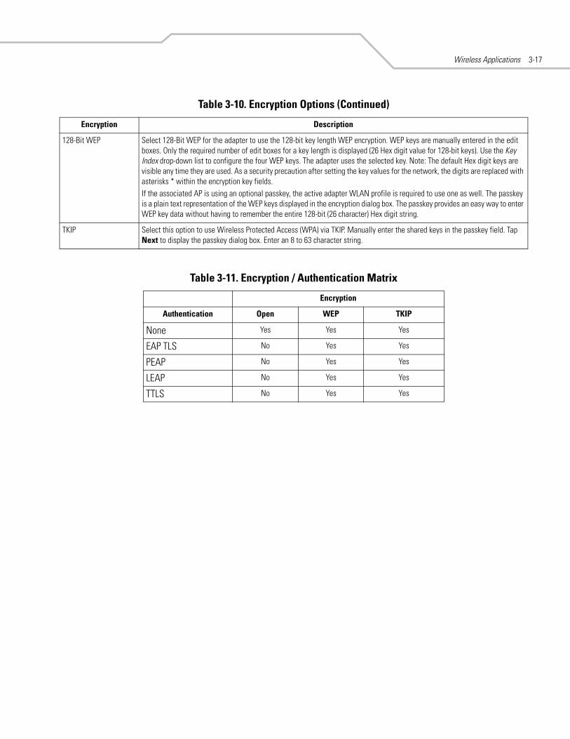
Table 3-10. Encryption Options
Encryption Description
Open Use the Open option as the default setting when no data packet encryption is needed over the network. Selecting this option provides no security for the data being transmitted over the network.
40-Bit WEP Select 40-Bit WEP for the adapter to use the 40-bit key length WEP encryption. WEP keys are manually entered in the edit boxes. Only the required number of edit boxes for a key length is displayed (10 Hex digit value for 40-bit keys). Use the Key Index drop-down list to configure the four WEP keys. The adapter uses the selected key. Note: The default Hex digit keys are visible any time they are used. As a security precaution after setting the key values for the network, the digits are replaced with asterisks * within the encryption key fields. If the associated AP is using an optional passkey, the active adapter WLAN profile is required to use one as well. The passkey is a plain text representation of the WEP keys displayed in the encryption dialog box. The passkey provides an easy way to enter WEP key data without having to remember the entire 40-bit (10 character) Hex digit string.
Wireless Applications 3-17
128-Bit WEP Select 128-Bit WEP for the adapter to use the 128-bit key length WEP encryption. WEP keys are manually entered in the edit boxes. Only the required number of edit boxes for a key length is displayed (26 Hex digit value for 128-bit keys). Use the Key Index drop-down list to configure the four WEP keys. The adapter uses the selected key. Note: The default Hex digit keys are visible any time they are used. As a security precaution after setting the key values for the network, the digits are replaced with asterisks * within the encryption key fields.If the associated AP is using an optional passkey, the active adapter WLAN profile is required to use one as well. The passkey is a plain text representation of the WEP keys displayed in the encryption dialog box. The passkey provides an easy way to enter WEP key data without having to remember the entire 128-bit (26 character) Hex digit string.
TKIP Select this option to use Wireless Protected Access (WPA) via TKIP. Manually enter the shared keys in the passkey field. Tap Next to display the passkey dialog box. Enter an 8 to 63 character string.
Table 3-11. Encryption / Authentication Matrix
Encryption
Authentication Open WEP TKIP
None Yes Yes Yes
EAP TLS No Yes Yes
PEAP No Yes Yes
LEAP No Yes Yes
TTLS No Yes Yes
Table 3-10. Encryption Options (Continued)
Encryption Description

MC9000 Series Addendum for Embedded Windows CE 5.03-18
Key Entry PageIf either 40-Bit WEP or 128-Bit WEP is selected the wizard proceeds to the key entry dialog box unless the Use Passkey check box was selected in the Encryption Dialog Box (see Figure 3-21 on page 3-16). To enter the key information:
1. Enter the 40-bit or 128-bit keys into the fields.2. Tap Next.
Figure 3-22. 40-Bit WEP Keys Dialog Box
Figure 3-23. 128-Bit WEP Keys Dialog Box
Passkey DialogWhen a user selects None as an authentication and WEP as an encryption, the user can chose to enter a passkey by checking the Use PassKey check box. The user is prompted to enter the passkey. For WEP, the Use PassKey checkbox is only available if the authentication is None.
When a user selects None as an authentication and TKIP as an encryption, the user is forced to enter a passkey. The user cannot enter a passkey if the encryption is TKIP and the authentication is anything other than None.
Figure 3-24. Passkey Dialog Box
Tap Next. The IP Mode dialog box displays.

Wireless Applications 3-19
IP ModeUse the IP Mode dialog box to configure network address parameters: IP address, subnet, gateway, DNS and WINS.
Figure 3-25. IP Config Tab (DHCP)
Select either DHCP or Static from the drop-down list and then tap Next. If Static IP is selected, the IP Address Entry dialog box displays. If DHCP is selected, the Transmit Power dialog box displays.
IP Address EntryUse the IP Address Entry dialog box to enter the IP address and subnet information.
Figure 3-26. Static IP Address Entry Dialog Box
Table 3-12. IP Mode Options
Encryption Description
DHCP Select Dynamic Host Configuration Protocol (DHCP) from the IP Mode drop-down list to obtain a leased IP address and network configuration information from a remote server. DHCP is the default setting for the mobile computer profile. When DHCP is selected, the IP address fields are read-only.
Static Select Static to manually assign the IP, subnet mask, default gateway, DNS and WINS addresses used by the mobile computer profile.
Table 3-13. Static IP Address Entry Fields
Field Description
IP Address The Internet is a collection of networks with users that communicate with each other. Each communication carries the address of the source and destination networks and the particular machine within the network associated with the user or host computer at each end. This address is called the IP address (Internet Protocol address). Each node on the IP network must be assigned a unique IP address that is made up of a network identifier and a host identifier. Enter the IP address as a dotted-decimal notation with the decimal value of each octet separated by a period, for example, 192.168.7.27.
Subnet Mask Most TCP/IP networks use subnets in order to effectively manage routed IP addresses. Having an organization's network divided into subnets allows it to be connected to the Internet with a single shared network address, for example, 255.255.255.0.

MC9000 Series Addendum for Embedded Windows CE 5.03-20
Select the Advanced check box to enter additional address information.
If the Advanced check box is selected then tapping NEXT displays the Advanced Address Entry dialog box to enter the Gateway, DNS, and WINS address. If the Advanced check box is not selected then tapping NEXT displays the Transmit Power dialog box.
Figure 3-27. Advanced Address Entry Dialog Box
The IP information that is entered in the profile is only used when the Enable IP Mgmt check box is enabled in the Options - System Options dialog box (System Options on page 3-39). When Enable IP Mgmt check box is disabled, the IP information in the profile is ignored and the IP information entered in the Microsoft interface applies.
Tap Next. The Transmit Power dialog box displays.
Transmit PowerThe transmit power can be selected for both Ad-Hoc and Infrastructure network types. The Transmit Power drop-down list contains different options for each mode. Automatic (i.e. use the current AP settings) and Power Plus (use higher than the current AP settings) are available for Infrastructure mode.
Adjusting the Radio Transmission Power level enables the user to expand or confine the transmission area with respect to other wireless devices that could be operating nearby. Reducing a coverage area in high traffic areas improves transmission quality by reducing the amount of interference in that coverage area.
Figure 3-28. Transmit Power Dialog Box (Infrastructure Mode)
Table 3-14. IP Config Advanced Address Entry Fields
Field Description
G/W The default Gateway is a device that is used to forward IP packets to and from a remote destination.
DNS The Domain Name System (DNS) is a distributed Internet directory service. DNS is used mostly to translate domain names and IP addresses. It is also used to control Internet email delivery. Most Internet service requires DNS to operate properly. If DNS is not configured, Web sites cannot be located and/or email delivery fails.
WINS WINS is a Microsoft® Net BIOS name server. WINS eliminates the broadcasts needed to resolve computer names to IP addresses by providing a cache or database of translations.
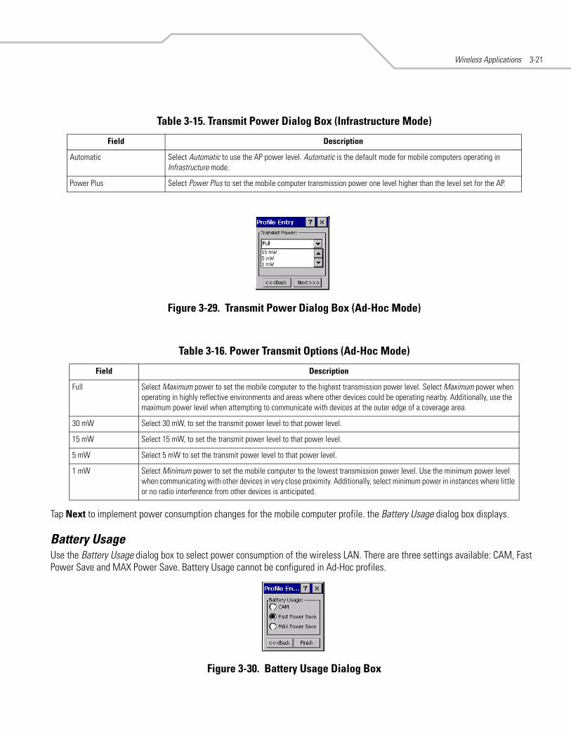
Wireless Applications 3-21
Figure 3-29. Transmit Power Dialog Box (Ad-Hoc Mode)
Tap Next to implement power consumption changes for the mobile computer profile. the Battery Usage dialog box displays.
Battery UsageUse the Battery Usage dialog box to select power consumption of the wireless LAN. There are three settings available: CAM, Fast Power Save and MAX Power Save. Battery Usage cannot be configured in Ad-Hoc profiles.
Figure 3-30. Battery Usage Dialog Box
Table 3-15. Transmit Power Dialog Box (Infrastructure Mode)
Field Description
Automatic Select Automatic to use the AP power level. Automatic is the default mode for mobile computers operating in Infrastructure mode.
Power Plus Select Power Plus to set the mobile computer transmission power one level higher than the level set for the AP.
Table 3-16. Power Transmit Options (Ad-Hoc Mode)
Field Description
Full Select Maximum power to set the mobile computer to the highest transmission power level. Select Maximum power when operating in highly reflective environments and areas where other devices could be operating nearby. Additionally, use the maximum power level when attempting to communicate with devices at the outer edge of a coverage area.
30 mW Select 30 mW, to set the transmit power level to that power level.
15 mW Select 15 mW, to set the transmit power level to that power level.
5 mW Select 5 mW to set the transmit power level to that power level.
1 mW Select Minimum power to set the mobile computer to the lowest transmission power level. Use the minimum power level when communicating with other devices in very close proximity. Additionally, select minimum power in instances where little or no radio interference from other devices is anticipated.

MC9000 Series Addendum for Embedded Windows CE 5.03-22
Power consumption is also related to the transmit power settings.
Manage Profiles ApplicationThe Manage Profiles window provides a list of user configured wireless profiles. Up to 32 profiles can be defined at any one time. To open the Manage Profiles window, tap the Signal Strength icon - Manage Profiles. The Manage Profiles window displays.
Figure 3-31. Manage Profiles Window
Icons next to each profile identify the profiles current state.
Table 3-17. Battery Usage Options
Field Description
CAMContinuous Aware Mode (CAM) provides the best network performance, but yields the shortest battery life.
Fast Power SaveFast Power Save performs in the middle of CAM and MAX Power Save with respect to network performance and battery life. Default.
MAX Power Save
Max Power Save yields the longest battery life while potentially reducing network performance. In networks with minimal latency. Max Power Save will perform just as well as Fast Power Save, but with increased battery savings.
Table 3-18. Profile Icons
Icon Description
No Icon Profile is not selected, but enabled.
Profile is disabled.
Profile is Cancelled. A Cancelled profile is disabled until a connect or login function is performed through the configuration editor.
Profile is currently in use and describes an infrastructure profile not using encryption.
Profile is currently in use and describes an infrastructure profile using encryption.
Profile is currently in use and describes an ad-hoc profile not using encryption.

Wireless Applications 3-23
The profiles are listed in priority order for use by the automatic roaming feature. Change the order by moving profiles up or down. Edit existing profiles by selecting one in the list and then tap-and-hold to display the menu. The menu allows the selected profile to be connected, edited, disabled (enabled) or deleted. (Note: the Disable menu item changes to Enable if the profile is already disabled.)
Figure 3-32. Manage Profiles Context Menu
A dialog displays to confirm the users desire to delete a profile, if selected.
Changing ProfilesA completed profile is a set of configuration settings that can be used in different locations to connect to a wireless network. Creating different profiles is a good way of having pre-defined operating parameters available for use in various network environments. When the WLAN Profiles window initially displays, existing profiles appear in the list.
Figure 3-33. Manage Profiles
Select a profile from the list. Select Connect from the pop-up menu to set that profile as the active profile. Once selected, the mobile computer uses the authentication, encryption, ESSID, IP Config and power consumption settings initially configured for that profile.
Profile is currently in use and describes an ad-hoc profile using encryption.
Profile is not valid in the device current operating regulatory domain.
Table 3-18. Profile Icons (Continued)

MC9000 Series Addendum for Embedded Windows CE 5.03-24
Editing a ProfileSelect a profile from the list. Select Edit from the pop-up menu to display the Profile Wizard where the ESSID and operating mode can be changed for the profile. Use the wizard to edit the profile power consumption and security parameters. See Profile Editor Wizard on page 3-6 for procedure on using the wizard.
Creating a New ProfileCreate new profiles from the Manage Profiles window by performing a tap-and-hold anywhere in this window. A menu with only the Add highlighted displays.
Figure 3-34. Manage Profiles - Add
Select Add to display the Profile Wizard wherein the profile name and ESSID can be set. Use the Profile Wizard to set security, network address information and power consumption level for the new profile.
Deleting a ProfileTo delete a profile from the list and select Delete from the pop-up menu. A confirmation dialog box appears.
Ordering ProfilesSelect a profile from the list and select Move Up or Move Down from the pop-up to order the profile. If the current profile association is lost, the mobile computer attempts to associate with the first profile in the list and then the next until a new association is achieved.
Profile Roaming must be enabled.

Wireless Applications 3-25
Export a ProfileTo export a profile to a registry file, select a profile from the list and select Export from the pop-up menu. The save As dialog box displays with the Application folder and a default name of WCS_PROFILE{profile GUID}.reg (Globally Unique Identifier).
Figure 3-35. Save As Dialog Box
If required, change the Name field and tap OK. A confirmation dialog box appears after the export is complete.

MC9000 Series Addendum for Embedded Windows CE 5.03-26
Wireless Status ApplicationThe Wireless Status application window displays the current wireless connection status and information about the wireless connection.
To open the Wireless Status window, tap the Signal Strength icon - Wireless Status. The Wireless Status window displays.
Figure 3-36. Wireless Status Window
The Wireless Status window contains the following options. Tap the option to display the option window.
• Signal Strength - provides information about the connection status of the current wireless profile.• Current Profile - displays basic information about the current profile and connection settings• IPv4 Status - displays the current IP address, subnet and other IP related information assigned to the mobile computer• Wireless Log - displays a log of important recent activity, such as authentication, association, DHCP renewal completion, in
time order• Versions - displays software, firmware and hardware version numbers• Quit - Exits the Wireless Status window.
Option windows contain a back button to return to the main Wireless Status window.
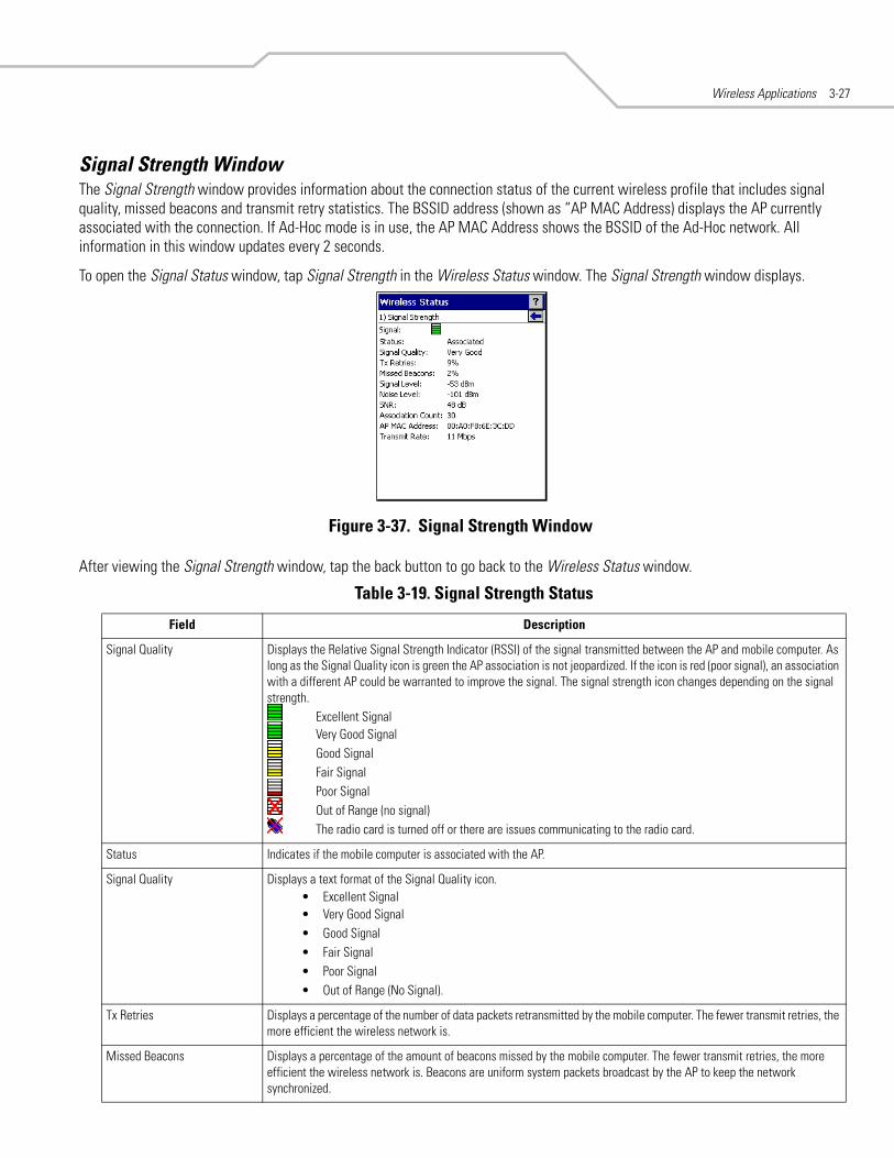
Wireless Applications 3-27
Signal Strength WindowThe Signal Strength window provides information about the connection status of the current wireless profile that includes signal quality, missed beacons and transmit retry statistics. The BSSID address (shown as “AP MAC Address) displays the AP currently associated with the connection. If Ad-Hoc mode is in use, the AP MAC Address shows the BSSID of the Ad-Hoc network. All information in this window updates every 2 seconds.
To open the Signal Status window, tap Signal Strength in the Wireless Status window. The Signal Strength window displays.
Figure 3-37. Signal Strength Window
After viewing the Signal Strength window, tap the back button to go back to the Wireless Status window.
Table 3-19. Signal Strength Status
Field Description
Signal Quality Displays the Relative Signal Strength Indicator (RSSI) of the signal transmitted between the AP and mobile computer. As long as the Signal Quality icon is green the AP association is not jeopardized. If the icon is red (poor signal), an association with a different AP could be warranted to improve the signal. The signal strength icon changes depending on the signal strength.
Excellent SignalVery Good SignalGood SignalFair SignalPoor SignalOut of Range (no signal)The radio card is turned off or there are issues communicating to the radio card.
Status Indicates if the mobile computer is associated with the AP.
Signal Quality Displays a text format of the Signal Quality icon.• Excellent Signal• Very Good Signal• Good Signal• Fair Signal• Poor Signal• Out of Range (No Signal).
Tx Retries Displays a percentage of the number of data packets retransmitted by the mobile computer. The fewer transmit retries, the more efficient the wireless network is.
Missed Beacons Displays a percentage of the amount of beacons missed by the mobile computer. The fewer transmit retries, the more efficient the wireless network is. Beacons are uniform system packets broadcast by the AP to keep the network synchronized.

MC9000 Series Addendum for Embedded Windows CE 5.03-28
Signal Level The AP signal level in decibels per milliwatt (dBm).
Noise Level The background interference (noise) level in decibels per milliwatt (dBm).
SNR The access point/mobile computer Signal to Noise Ratio (SNR) of signal strength to noise (interference) in decibels per milliwatt (dBm).
Roaming Count Displays the number of APs that the mobile computer has connect to while roaming.
AP MAC Address Displays the MAC address of the AP to which the mobile computer is currently connected to.
Transmit Rate Displays the current rate of the data transmission.
Table 3-19. Signal Strength Status (Continued)
Field Description

Wireless Applications 3-29
Current Profile WindowThe Current Profile window displays basic information about the current profile and connection settings. This window updates every two seconds.
To open the Current Profile window, tap Current Profile in the Wireless Status window. The Current Profile window displays.
Figure 3-38. Current Profile Window
Table 3-20. Current Profile Fields
Field Description
Profile Name Displays the current profile name that the mobile computer is using to communicate with the AP.
ESSID Displays the current profile ESSID name.
Mode Displays the current profile mode, either Infrastructure or Ad-Hoc.
Authentication Displays the current profile’s authentication type.
Encryption Displays the current profile’s encryption type.
Channel Displays the current profile channel setting.
Country Displays the current profile country setting.
Transmit Power Displays the radio transmission power level.

MC9000 Series Addendum for Embedded Windows CE 5.03-30
IPv4 Status WindowThe IPv4 Status window displays the current IP address, subnet and other IP related information assigned to the mobile computer. It also allows the address to be renewed if it the profile is currently using DHCP to obtain the IP information. When the user tap Renew a full DHCP discover initiates. The IPv4 Status window should update automatically when the IP address changes.
To open the IPv4 Status window, tap IPv4 Status in the Wireless Status window. The IPv4 Status window displays.
Figure 3-39. IPv4 Status Window
Table 3-21. IPv4 Status Fields
Field Description
IP Type DIsplays the IP type for the current profile, either DHCP or Static. If the current IP type is DHCP, leased IP address and network address data display for the mobile computer. If the current IP type is Static, the values displayed were input manually in the IP Config tab on page 3-19.
IP Address Displays the IP address assigned to the mobile computer. The Internet is a collection of networks with users that communicate with each other. Each communication carries the address of the source and destination networks and the particular machine within the network associated with the user or host computer at each end. This address is called the IP address. Each node on the IP network must be assigned a unique IP address that is made up of a network identifier and a host identifier. The IP address as a dotted-decimal notation with the decimal value of each octet separated by a period, for example, 192.168.7.27.
Subnet Displays the subnet address. Most TCP/IP networks use subnets in order to effectively manage routed IP addresses. Having an organization's network divided into subnets allows it to be connected to the Internet with a single shared network address, for example, 255.255.255.0.
Gateway Displays the gateway address. A gateway is a device that is used to forward IP packets to and from a remote destination.
DHCP Server The Domain Name System (DNS) is a distributed Internet directory service. DNS is used mostly to translate domain names and IP addresses. It is also used to control Internet e-mail delivery. Most Internet service requires DNS to operate properly. If DNS is not configured, Web sites cannot be located or e-mail delivery fails.
Lease Obtained Displays the date that the IP Address was obtained.
Lease Expires Displays the date that the IP Address expires and a new IP Address is requested.
DNS Displays the IP Address of the DNS server.
WINS WINS is a Microsoft Net BIOS name server. WINS eliminates the broadcasts needed to resolve computer names to IP addresses by providing a cache or database of translations.
MAC An IEEE 48-bit address the mobile computer is assigned at the factory that uniquely identifies the adapter at the physical layer.
Host Name Displays the name of the mobile computer.

Wireless Applications 3-31
Wireless Log WindowThe Wireless Log window displays a log of important recent activity, such as authentication, association, DHCP renewal completion, in time order. Users can choose to save the log to a file or to clear the log (within this instance of the application only). There is also an auto scroll feature to automatically scroll down when new items are added to the log.
To open the Wireless Log window, tap Wireless Log in the Wireless Status window. The Wireless Log window displays.
Figure 3-40. Wireless Log Window
Saving a LogTo save a Wireless Log:
1. Tap the Save button. The Save As dialog box displays.2. Navigate to the desired folder.3. In the Name filed, enter a file name and then tap OK. A text file is saved in the selected folder.
Clear the LogTo clear the log, tap Clear.
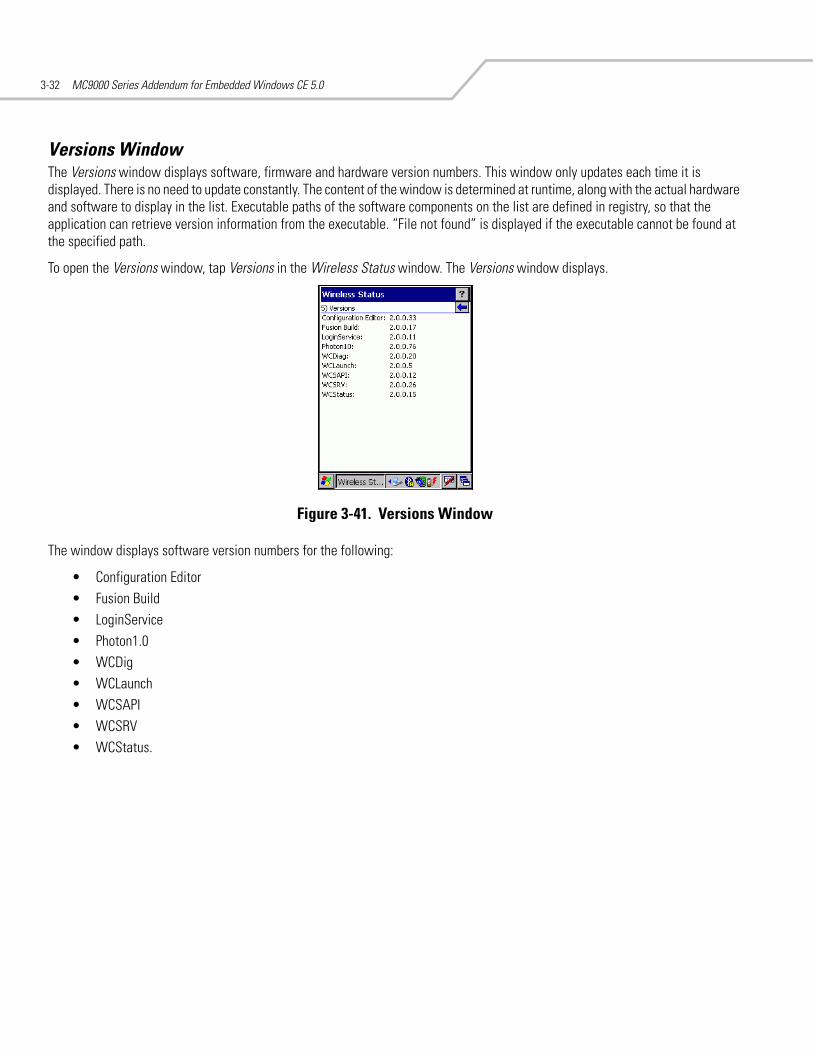
MC9000 Series Addendum for Embedded Windows CE 5.03-32
Versions WindowThe Versions window displays software, firmware and hardware version numbers. This window only updates each time it is displayed. There is no need to update constantly. The content of the window is determined at runtime, along with the actual hardware and software to display in the list. Executable paths of the software components on the list are defined in registry, so that the application can retrieve version information from the executable. “File not found” is displayed if the executable cannot be found at the specified path.
To open the Versions window, tap Versions in the Wireless Status window. The Versions window displays.
Figure 3-41. Versions Window
The window displays software version numbers for the following:
• Configuration Editor• Fusion Build• LoginService• Photon1.0• WCDig• WCLaunch• WCSAPI• WCSRV• WCStatus.

Wireless Applications 3-33
Wireless Diagnostics ApplicationThe Wireless Diagnostics application window provides links to perform ICMP Ping, Trace Routing and Known APs.
To open the Wireless Diagnostics window, tap the Signal Strength icon - Wireless Diagnostics. The Wireless Diagnostics window displays.
Figure 3-42. Wireless Diagnostics Window
The Wireless Diagnostics window contains the following options. Tap the option to display the option window.
• ICMP Ping - tests the wireless network connection.• Trace Route - tests a connection at the network layer between the mobile computer and any place on the network.• Known APs - displays the APs in range using the same ESSID as the mobile computer.• Quit - Exits the Wireless Diagnostics window.
Option windows contain a back button to return to the main Wireless Diagnostics window.

MC9000 Series Addendum for Embedded Windows CE 5.03-34
ICMP Ping WindowThe ICMP Ping window allows a user to test a connection at the network layer (part of the IP protocol), between the mobile computer and an AP. Ping tests only stop when the user taps the Stop Test button, closes the Wireless Diagnostics application, or if the mobile computer switches between infrastructure and ad-hoc modes.
To open the ICMP Ping window, tap the ICMP Ping in the Wireless Diagnostics window. The ICMP Ping window displays.
Figure 3-43. ICMP Ping Window
To perform an ICMP ping:
1. In the IP field, enter an IP address or select an IP address from the drop-down list.2. From the Size drop-down list, select a size value.3. Tap Start Test. The ICMP Ping test starts. Information of the ping test displays in the appropriate fields.

Wireless Applications 3-35
Trace Route WindowTrace Route traces a packet from a computer to a host, showing how many hops the packet requires to reach the host and how long each hop takes. The Trace Route utility identifies where the longest delays are occurring.
The Trace Route window allows a user to test a connection at the network layer (part of the IP protocol), between the mobile computer and any place on the network.
To open the Trace Route window, tap Trace Route in the Wireless Diagnostics window. The Trace Route window dispalys.
Figure 3-44. Trace Route Window
A user can enter an IP address or a DNS Name in the IP combo box, and tap Start Test. The IP combo box should match the same information as shown in the ICMP Ping window’s IP combo box. When a test is started, the trace route attempts to find all routers between the mobile computer and the destination. The Round Trip Time (RTT) between the mobile computer and each router is shown, and then the total test time is also shown. The total test time may be longer than all RTTs added together because it is not just including time on the network.

MC9000 Series Addendum for Embedded Windows CE 5.03-36
Known APs WindowThe Known APs window displays the APs in range using the same ESSID as the mobile computer. This window only available when in the Infrastructure mode.
To open the Known APs window, tap Known APs in the Wireless Diagnostics window. The Known APs window displays.
Figure 3-45. Known APs Window
The icon next to the AP indicates:
Tapping and holding the stylus on a specific AP displays a context sensitive menu with the options: Set Mandatory and Set Roaming.
Selecting the Set Mandatory option prohibits the mobile computer from associating with a different AP. The letter M displays on top of the icon when the Set Mandatory option is selected. The mobile computer connects to the selected AP and never roams until:
• Set Roaming is chosen• The mobile computer roams to a new profile• The mobile computer is suspended• The mobile computer resets (warm or cold).
Selecting Set Roaming allows the mobile computer to roam to any AP with a better signal. These settings are temporary and never saved to the registry.
Tap Refresh to update the list of the APs with the same ESSID. A signal strength value of 32 is the highest possible.
The AP is the currently associated access point, and it is set to mandatory.
The AP is the currently associated access point, but it is not set to mandatory.
The mobile computer is not currently associated to this AP, but the AP is set as mandatory.
The mobile computer is not currently associated to this AP, and AP is not set as mandatory.
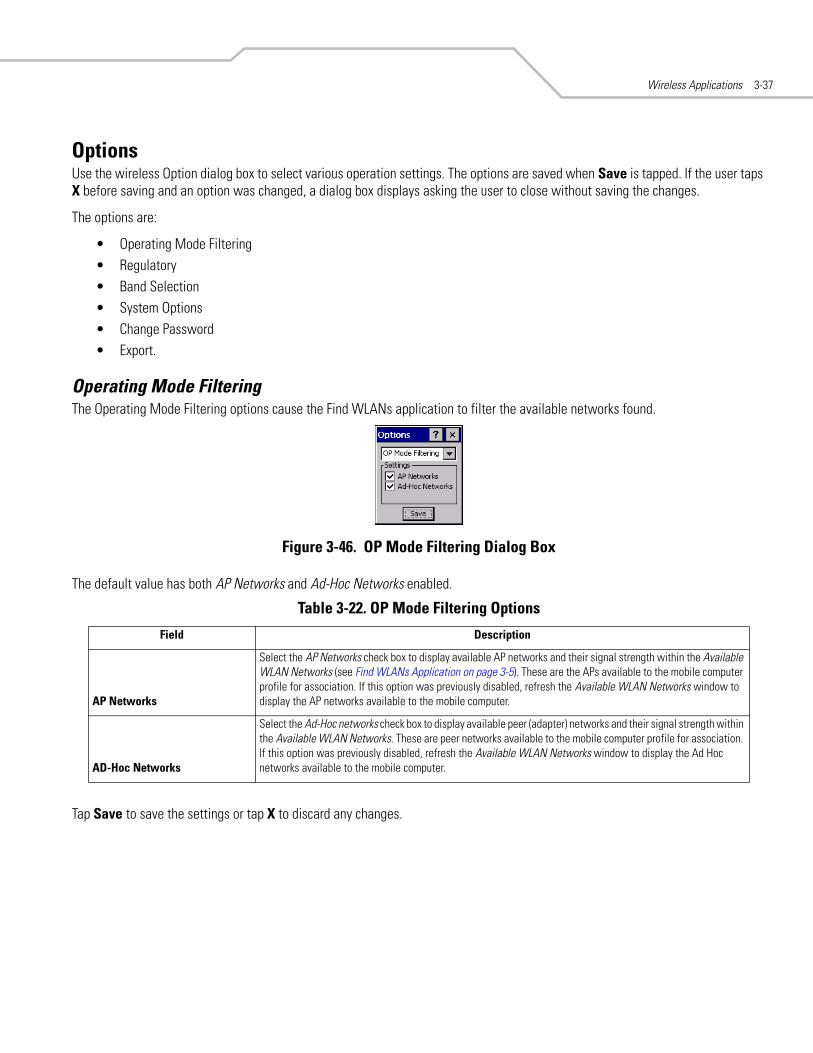
Wireless Applications 3-37
OptionsUse the wireless Option dialog box to select various operation settings. The options are saved when Save is tapped. If the user taps X before saving and an option was changed, a dialog box displays asking the user to close without saving the changes.
The options are:
• Operating Mode Filtering• Regulatory• Band Selection• System Options• Change Password• Export.
Operating Mode FilteringThe Operating Mode Filtering options cause the Find WLANs application to filter the available networks found.
Figure 3-46. OP Mode Filtering Dialog Box
The default value has both AP Networks and Ad-Hoc Networks enabled.
Tap Save to save the settings or tap X to discard any changes.
Table 3-22. OP Mode Filtering Options
Field Description
AP Networks
Select the AP Networks check box to display available AP networks and their signal strength within the Available WLAN Networks (see Find WLANs Application on page 3-5). These are the APs available to the mobile computer profile for association. If this option was previously disabled, refresh the Available WLAN Networks window to display the AP networks available to the mobile computer.
AD-Hoc Networks
Select the Ad-Hoc networks check box to display available peer (adapter) networks and their signal strength within the Available WLAN Networks. These are peer networks available to the mobile computer profile for association. If this option was previously disabled, refresh the Available WLAN Networks window to display the Ad Hoc networks available to the mobile computer.

MC9000 Series Addendum for Embedded Windows CE 5.03-38
Regulatory OptionsUse the Regulatory settings to configure the country the mobile computer is in. Due to regulatory requirements (within a country) a mobile computer is only allowed to use certain channels.
Figure 3-47. Regulatory Options Dialog Box
Band SelectionThe Band Selection settings identify the frequency bands to be scanned when finding WLANs. These values refer to the 802.11 standard networks.
Figure 3-48. Band Selection Dialog Box
Tap Save to save the settings or tap X to discard any changes.
Table 3-23. Regulatory Options
Field Description
SettingsSelect the country of use from the drop-down list. In order to connect to a profile, the profile country must match this setting, or the AP country setting if the Enable 802.11d check box is selected.
Enable 802.11d
With this check box selected, the WLAN adapter attempts to retrieve the country from APs. Profiles which use Infrastructure mode are only able to connect if the country set is the same as the AP country settings or if the profile country setting is set to Allow Any Country. Check this box requires that ALL APs be configured to transmit the country information.
Table 3-24. Band Selection Options
Field Description
5GHz Band With this box checked, the Find WLANs application list includes all networks found in the 5 GHz band (802.11a).
2.4GHz Band With this box checked, the Find WLANs application list includes all networks found in the 2.4 GHz band (802.11b and 802.11g).

Wireless Applications 3-39
System OptionsUse the system options to set miscellaneous system setting.
Figure 3-49. System Options Dialog Box
Table 3-25. Band Selection Options
Field Description
Profile RoamingSelect the Profile Roaming check box to configure the mobile computer to roam to the next available WLAN profile when it moves out of range of the current WLAN profile.
Enable IP Mgmt
Select Enable IP Mgmt check box to enable the Wireless Companion Services to handle IP Address management. When checked, the Wireless Companion Service configures the IP based on what is configured in the network profile. If unchecked, the Wireless Companion Service does not configure the IP information. For this case, the user must configure the IP in the standard Windows IP dialog screen. Enabled by default.
Auto Time Config
Select Auto Time Config check box to enable automatic update of the system time. The device time is updated during network association, based on the time as set in the AP. This proprietary feature is only supported with Symbol infrastructure. Enabled by default.

MC9000 Series Addendum for Embedded Windows CE 5.03-40
Change Password Dialog BoxUse the Change Password dialog box to require a password before any profile can be edited. This allows system administrators to pre-configure profiles and not allow a user to change the network settings. The user could also use this feature to protect their settings from a guest user. By default, the password is not set.
Figure 3-50. Change Password Window
1. To create a password for the first time, leave the Current: text box empty and enter the new password in the New: and Confirm: text boxes. Tap Save.
2. To change an existing password, enter the current password in the Current: text box, enter the new password in the New: and Confirm: text boxes.Tap Save.
3. Delete the password, in this case enter the current password in the Current: text box and leave the New: and Confirm: text boxes empty.
Passwords are case sensitive and can not exceed 10 characters.
ExportUse the Export dialog box to export all profiles to a registry file, and to export the options to a registry file. Each of these export functions prompts the user for a filename that is used as the registry file. The “save” dialog box defaults to the application folder, and has a default file name to use. For exporting all profiles, the default filename is: WCS_PROFILES.REG. For exporting the options, the default filename is: WCS_OPTIONS.REG.
Figure 3-51. Options - Export Dialog Box

Wireless Applications 3-41
To export options:
1. Tap Export Options. The Save As dialog box displays.
Figure 3-52. Export Options Save As Dialog Box
2. The default folder is \Application\FusionApps\Certs\.3. In the Name field, enter a file name.4. Tap OK.
To export all profiles:
1. Tap Export All Profiles. The Save As dialog box displays.
Figure 3-53. Export All Profiles Save AS Dialog Box
2. Navigate to the desired folder.3. In the Name field, enter a file name.4. Tap OK.
When Export All Profiles is selected the current profile is also saved. This information is used to determine which profile to connect with after a warm boot or cold boot.

MC9000 Series Addendum for Embedded Windows CE 5.03-42
Cold Boot PersistenceExporting options and profiles can be used to provide cold boot persistence. If the exported registry files are saved in the Application folder, they are automatically utilized on a cold boot, restoring previous profile and option settings.
Currently, only server certificates can be saved for cold boot persistence. To save server certificates for cold boot persistence, the certificate files must be placed in the folder Application\Certs. Saving the certificates to this folder causes the certificates to be installed automatically on a cold boot.
User certificates cannot be saved for cold boot persistence at this time.
Registry SettingsSome of the parameters can be modified through a registry key. The registry path is:
HKLM\SOFTWARE\Symbol Technologies, Inc.\Configuration Editor
Table 3-26. Registry Parameter Settings
Key Type Default Description
CertificateDirectory REG_SZ \\Windows The default directory to find certificates.
EncryptionMask REG_DWORD 0x0000001F Defines the encryption types that are currently supported. This is a bitwise mask with each bit corresponding to an encryption type. 1 = Type is supported, 0 = Type is not supported
Bit Number Encryption Type0 None1 40-Bit WEP2 128-Bit WEP3 TKIP
MenuShortCut REG_SZ Alt-M Describes the key combination to use in place of Tap-and-hold or shortcut key sequence to display menus. This value can be a system key sequence (i.e. preceded with ALT) or a single key which triggers the context sensitive menu when the appropriate dialog is visible.
RefreshTime REG_DWORD 4000 This registry key defines the number of milliseconds between refreshes of the Manage Profiles dialog.
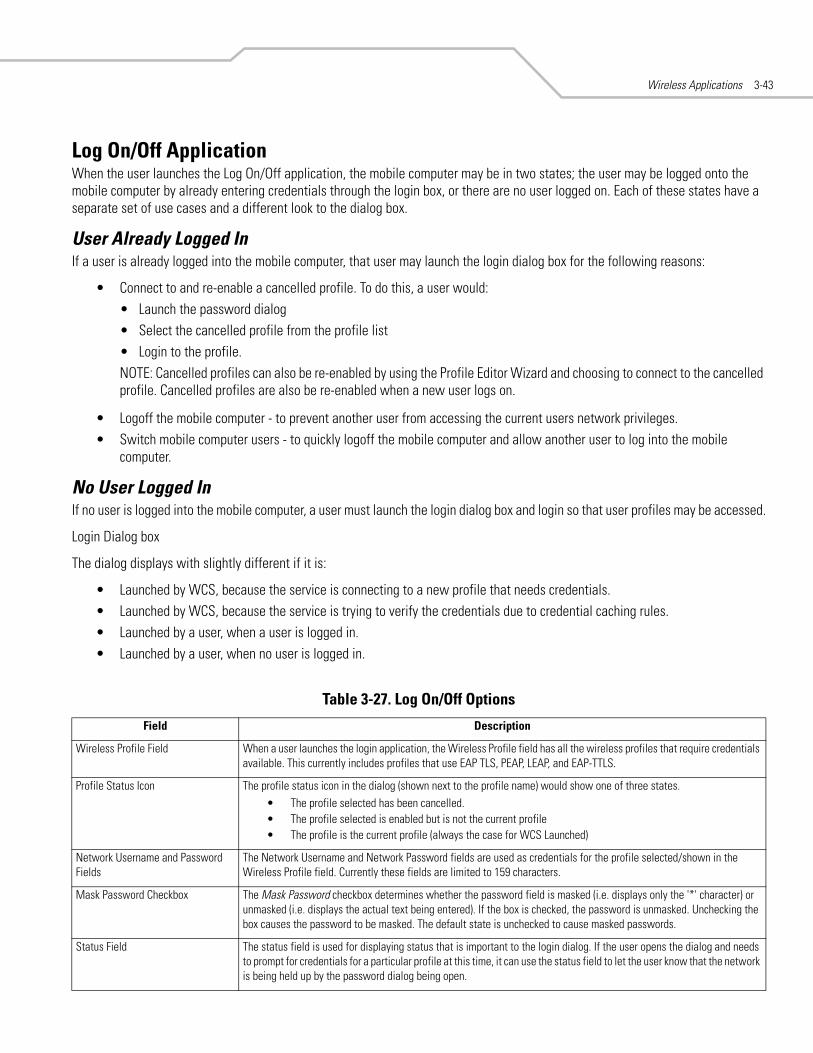
Wireless Applications 3-43
Log On/Off ApplicationWhen the user launches the Log On/Off application, the mobile computer may be in two states; the user may be logged onto the mobile computer by already entering credentials through the login box, or there are no user logged on. Each of these states have a separate set of use cases and a different look to the dialog box.
User Already Logged InIf a user is already logged into the mobile computer, that user may launch the login dialog box for the following reasons:
• Connect to and re-enable a cancelled profile. To do this, a user would:• Launch the password dialog• Select the cancelled profile from the profile list• Login to the profile.NOTE: Cancelled profiles can also be re-enabled by using the Profile Editor Wizard and choosing to connect to the cancelled profile. Cancelled profiles are also be re-enabled when a new user logs on.
• Logoff the mobile computer - to prevent another user from accessing the current users network privileges.• Switch mobile computer users - to quickly logoff the mobile computer and allow another user to log into the mobile
computer.
No User Logged InIf no user is logged into the mobile computer, a user must launch the login dialog box and login so that user profiles may be accessed.
Login Dialog box
The dialog displays with slightly different if it is:
• Launched by WCS, because the service is connecting to a new profile that needs credentials.• Launched by WCS, because the service is trying to verify the credentials due to credential caching rules.• Launched by a user, when a user is logged in.• Launched by a user, when no user is logged in.
Table 3-27. Log On/Off Options
Field Description
Wireless Profile Field When a user launches the login application, the Wireless Profile field has all the wireless profiles that require credentials available. This currently includes profiles that use EAP TLS, PEAP, LEAP, and EAP-TTLS.
Profile Status Icon The profile status icon in the dialog (shown next to the profile name) would show one of three states.• The profile selected has been cancelled.• The profile selected is enabled but is not the current profile• The profile is the current profile (always the case for WCS Launched)
Network Username and Password Fields
The Network Username and Network Password fields are used as credentials for the profile selected/shown in the Wireless Profile field. Currently these fields are limited to 159 characters.
Mask Password Checkbox The Mask Password checkbox determines whether the password field is masked (i.e. displays only the '*' character) or unmasked (i.e. displays the actual text being entered). If the box is checked, the password is unmasked. Unchecking the box causes the password to be masked. The default state is unchecked to cause masked passwords.
Status Field The status field is used for displaying status that is important to the login dialog. If the user opens the dialog and needs to prompt for credentials for a particular profile at this time, it can use the status field to let the user know that the network is being held up by the password dialog being open.

MC9000 Series Addendum for Embedded Windows CE 5.03-44
Tapping OK sends the credentials though WCS API. If there are no credentials entered, a dialog box displays informing the user which field was not entered.
The Log Off button only displays when a user is already logged on. When the Log Off button is tapped, the user is prompted with three options: Log Off, Switch Users, and Cancel. Switching users logs off the current user and re-initialize the login dialog box to be displayed for when there is no user logged on. Logging off logs off the current user and close the login dialog box. Tapping Cancel closes the Log Off dialog box and the Login dialog box displays.
When the user is logged off, the mobile computer only roams to profiles that do not require credentials or to profiles that were created with the credentials entered into the profile
The Cancel button closes the dialog without logging into the network. If the login dialog was launched by the wCS and not by the user, tapping Cancel first causes a message box to display a warning that the cancel disables the current profile. If the user still chooses to cancel the login at this point, the profile is cancelled.
Once a profile is cancelled, the profile is suppressed until a user actively re-enables it or a new user logs onto the mobile computer.

Index
Numerics2D bar codes . . . . . . . . . . . . . . . . . . . . . . . . . . . . . . .2-3
AActiveSync . . . . . . . . . . . . . . . . . . . . . . . . . . . . . . . x, 1-6ad-hoc mode . . . . . . . . . . . . . . . . . . . . . . . . . . . . . . .3-7ad-hoc networks . . . . . . . . . . . . . . . . . . . . . . . . . . .3-37aiming . . . . . . . . . . . . . . . . . . . . . . . . . . . . . . . . . . . .2-4AirBEAM . . . . . . . . . . . . . . . . . . . . . . . . . . . . . . . . . .1-6AP
known . . . . . . . . . . . . . . . . . . . . . . . . . . . . . . .3-36networks . . . . . . . . . . . . . . . . . . . . . . . . . . . . .3-37
authentication . . . . . . . . . . . . . . . . . . . . . . . . . 3-8, 3-29
Bbacklight
battery power . . . . . . . . . . . . . . . . . . . . . . . . . .2-5brightness . . . . . . . . . . . . . . . . . . . . . . . . . . . . .2-6external power . . . . . . . . . . . . . . . . . . . . . . . . .2-6
band selection . . . . . . . . . . . . . . . . . . . . . . . . . . . . .3-38battery
settings . . . . . . . . . . . . . . . . . . . . . . . . . . . 2-5, 2-7usage . . . . . . . . . . . . . . . . . . . . . . . . . . . . . . .3-21
beaconsmissed . . . . . . . . . . . . . . . . . . . . . . . . . . . . . . .3-27
bullets . . . . . . . . . . . . . . . . . . . . . . . . . . . . . . . . . . . . . ix
Ccertificates . . . . . . . . . . . . . . . . . . . . . . . . . . . . . . . .3-42
cold boot persistence . . . . . . . . . . . . . . . . . . . . . . . 3-42configurations . . . . . . . . . . . . . . . . . . . . . . . . . . . . . . .ixcontrol panel
backlight . . . . . . . . . . . . . . . . . . . . . . . . . . . . . 2-5keylight . . . . . . . . . . . . . . . . . . . . . . . . . . . . . . 2-7new features . . . . . . . . . . . . . . . . . . . . . . . . . . 2-5system information . . . . . . . . . . . . . . . . . . . . . 2-9
conventionsnotational . . . . . . . . . . . . . . . . . . . . . . . . . . . . . .ix
country . . . . . . . . . . . . . . . . . . . . . . . . . . . . . . . . . . 3-29country code . . . . . . . . . . . . . . . . . . . . . . . . . . . . . . . 3-7cradle . . . . . . . . . . . . . . . . . . . . . . . . . . . . . 1-4, 1-5, 1-6
Ddata capture
2D bar codes . . . . . . . . . . . . . . . . . . . . . . . . . . 2-3decode mode . . . . . . . . . . . . . . . . . . . . . . . . . . 2-3image capture mode . . . . . . . . . . . . . . . . . . . . 2-3imaging . . . . . . . . . . . . . . . . . . . . . . . . . . . . . . 2-3pick list mode . . . . . . . . . . . . . . . . . . . . . . 2-3, 2-4scanning . . . . . . . . . . . . . . . . . . . . . . . . . . . . . 2-3
DCP . . . . . . . . . . . . . . . . . . . . . . . . . . . 1-3, 1-4, 1-5, 1-6default gateway . . . . . . . . . . . . . . . . . . . . . . . . . . . 3-19demo . . . . . . . . . . . . . . . . . . . . . . . . . . . . . . . . . . . . . 1-3DHCP . . . . . . . . . . . . . . . . . . . . . . . . . . . . . . . . . . . 3-19
server . . . . . . . . . . . . . . . . . . . . . . . . . . . . . . . 3-30DNS . . . . . . . . . . . . . . . . . . . . . . . . . . . 3-19, 3-20, 3-30downgrading to Windows CE .NET 4.2 . . . . . . . . . . 1-6

MC9000 Series Addendum for Embedded Windows CE 5.0IN-2
Eencryption . . . . . . . . . . . . . . . . . . . . . . . . . . . 3-16, 3-29
icon . . . . . . . . . . . . . . . . . . . . . . . . . . . . . . . . . .3-5ESSID . . . . . . . . . . . . . . . . . . . . . . . . . . . . . . . . 3-6, 3-29external power . . . . . . . . . . . . . . . . . . . . . . . . . . 2-6, 2-7
Ffeatures . . . . . . . . . . . . . . . . . . . . . . . . . . . . . . . . .3, 2-3
control panel . . . . . . . . . . . . . . . . . . . . . . . . . . .2-5firewall . . . . . . . . . . . . . . . . . . . . . . . . .1-3, 1-4, 1-5, 1-6
Ggateway . . . . . . . . . . . . . . . . . . . . . . . . . . . . . . . . . .3-20
IICMP ping . . . . . . . . . . . . . . . . . . . . . . . . . . . . . . . . .3-34icons
AP . . . . . . . . . . . . . . . . . . . . . . . . . . . . . . . . . .3-36encryption . . . . . . . . . . . . . . . . . . . . . . . . . . . . .3-5profile . . . . . . . . . . . . . . . . . . . . . . . . . . . . . . .3-22signal strength . . . . . . . . . . . . . . . . . . . . . 3-4, 3-5
iDockIt . . . . . . . . . . . . . . . . . . . . . . . . . . . . . . . . . . . .2-5image capture mode . . . . . . . . . . . . . . . . . . . . . . . . .2-3imaging . . . . . . . . . . . . . . . . . . . . . . . . . . . . . . . . . . .2-3
aiming . . . . . . . . . . . . . . . . . . . . . . . . . . . . . . . .2-4operational modes . . . . . . . . . . . . . . . . . . . . . .2-3
information, service . . . . . . . . . . . . . . . . . . . . . . . . . . . xinfrastructure mode . . . . . . . . . . . . . . . . . . . . . . . . . .3-7initial program loader . . . . . . . . . . . . . . . . . . . . 1-3, 1-5installing Windows CE 5.0 . . . . . . . . . . . . . . . . . . . . .1-3
AirBEAM . . . . . . . . . . . . . . . . . . . . . . . . . . . . . .1-6SD card . . . . . . . . . . . . . . . . . . . . . . . . . . . . . . .1-6serial connection . . . . . . . . . . . . . . . . . . . . . . . .1-5USB . . . . . . . . . . . . . . . . . . . . . . . . . . . . . . . . . .1-3Windows 2000 . . . . . . . . . . . . . . . . . . . . . . . . .1-4Windows XP . . . . . . . . . . . . . . . . . . . . . . . . . . .1-3
IP address . . . . . . . . . . . . . . . . . . . . . . . . . . . . . . . . .3-19IP config
DNS . . . . . . . . . . . . . . . . . . . . . . . . . . . . . . . . .3-20gateway . . . . . . . . . . . . . . . . . . . . . . . . . . . . .3-20IP address . . . . . . . . . . . . . . . . . . . . . . . . . . . .3-19subnet mask . . . . . . . . . . . . . . . . . . . . . . . . . .3-19WINS . . . . . . . . . . . . . . . . . . . . . . . . . . . . . . . .3-20
IPL . . . . . . . . . . . . . . . . . . . . . . . . . . . . . . . . . . . . 1-3, 1-5
Kkeylight
battery power . . . . . . . . . . . . . . . . . . . . . . . . . .2-7enabling . . . . . . . . . . . . . . . . . . . . . . . . . . . . . .2-8external power . . . . . . . . . . . . . . . . . . . . . . . . .2-7tracking . . . . . . . . . . . . . . . . . . . . . . . . . . . . . . .2-8
known APs . . . . . . . . . . . . . . . . . . . . . . . . . . . . . . . .3-36
Ooperating mode . . . . . . . . . . . . . . . . . . . . . . . . . . . . .3-7
Ppassword
changing . . . . . . . . . . . . . . . . . . . . . . . . . . . . 3-40pick list mode . . . . . . . . . . . . . . . . . . . . . . . . . . . . . . 2-3
aiming . . . . . . . . . . . . . . . . . . . . . . . . . . . . . . . 2-4power
backlight settings . . . . . . . . . . . . . . . . . . . . . . 2-6keylight settings . . . . . . . . . . . . . . . . . . . . . . . 2-7
profilechanging . . . . . . . . . . . . . . . . . . . . . . . . . . . . 3-23creating . . . . . . . . . . . . . . . . . . . . . . . . . . . . . 3-24current . . . . . . . . . . . . . . . . . . . . . . . . . . . . . . 3-29deleting . . . . . . . . . . . . . . . . . . . . . . . . . . . . . 3-24editing . . . . . . . . . . . . . . . . . . . . . . . . . . . . . . 3-24ESSID . . . . . . . . . . . . . . . . . . . . . . . . . . . . . . . . 3-6export to registry file . . . . . . . . . . . . . . . . . . . 3-40exporting . . . . . . . . . . . . . . . . . . . . . . . . . . . . 3-25ID . . . . . . . . . . . . . . . . . . . . . . . . . . . . . . . . . . . 3-6managing . . . . . . . . . . . . . . . . . . . . . . . . . . . . 3-22name . . . . . . . . . . . . . . . . . . . . . . . . . . . . . . . . 3-6ordering . . . . . . . . . . . . . . . . . . . . . . . . . . . . . 3-24
profile editor . . . . . . . . . . . . . . . . . . . . . . . . . . . . . . . 3-6
Rrapid deployment . . . . . . . . . . . . . . . . . . . . . . . . . . . 1-3registry file . . . . . . . . . . . . . . . . . . . . . . . . . . . . . . . 3-40registry settings . . . . . . . . . . . . . . . . . . . . . . . . . . . 3-42regulatory options . . . . . . . . . . . . . . . . . . . . . . . . . . 3-38
Sscanning
imaging . . . . . . . . . . . . . . . . . . . . . . . . . . . . . . 2-3SD card . . . . . . . . . . . . . . . . . . . . . . . . . . . . . . . .1-3, 1-6security . . . . . . . . . . . . . . . . . . . . . . . . . . . . . . . . . . . 1-3Series 9000 demo . . . . . . . . . . . . . . . . . . . . . . . . . . . 1-3service information . . . . . . . . . . . . . . . . . . . . . . . . . . . . xsettings
backlight tracking . . . . . . . . . . . . . . . . . . . . . . 2-8battery . . . . . . . . . . . . . . . . . . . . . . . . . . . . . . . 2-5brightness . . . . . . . . . . . . . . . . . . . . . . . . . . . . 2-6external power . . . . . . . . . . . . . . . . . . . . . . . . . 2-6keylight . . . . . . . . . . . . . . . . . . . . . . . . . . . . . . 2-7system information . . . . . . . . . . . . . . . . . . . . . 2-9
signal strength . . . . . . . . . . . . . . . . . . . . . . . . .3-3, 3-27RSSI . . . . . . . . . . . . . . . . . . . . . . . . . . . . . . . . 3-27
SMDK for .NET . . . . . . . . . . . . . . . . . . . . . . . . . . . . . . . xstatic . . . . . . . . . . . . . . . . . . . . . . . . . . . . . . . . . . . . 3-19subnet mask . . . . . . . . . . . . . . . . . . . . . . . . . . . . . . 3-19symbol global customer interaction center . . . . . . . . i-xsystem information . . . . . . . . . . . . . . . . . . . . . . . . . . 2-9system options . . . . . . . . . . . . . . . . . . . . . . . . . . . . 3-39
TTCM . . . . . . . . . . . . . . . . . . . . . . . . . . . . . . . . . .1-3, 1-5terminal configuration manager . . . . . . . . . . . . .1-3, 1-5trace route . . . . . . . . . . . . . . . . . . . . . . . . . . . . . . . 3-35transmit power . . . . . . . . . . . . . . . . . . . . . . . .3-20, 3-29
Index IN-3
Uupgrading to Windows CE 5.0
AirBEAM . . . . . . . . . . . . . . . . . . . . . . . . . . . . . 1-6SD card . . . . . . . . . . . . . . . . . . . . . . . . . . . . . . . 1-6serial connection . . . . . . . . . . . . . . . . . . . . . . . 1-5USB connection . . . . . . . . . . . . . . . . . . . . . . . . 1-3Windows 2000 . . . . . . . . . . . . . . . . . . . . . . . . . 1-4Windows XP . . . . . . . . . . . . . . . . . . . . . . . . . . . 1-3
USB . . . . . . . . . . . . . . . . . . . . . . . . . . . . . . . . . . . . . . 1-3cable . . . . . . . . . . . . . . . . . . . . . . . . . . . . . . . . . 1-6cradle . . . . . . . . . . . . . . . . . . . . . . . . . 1-4, 1-5, 1-6
WWavelink TN Client . . . . . . . . . . . . . . . . . . . . . . . . . . 1-3WINS . . . . . . . . . . . . . . . . . . . . . . . . . . . 3-19, 3-20, 3-30wireless diagnostics . . . . . . . . . . . . . . . . . . . . . . . . 3-33wireless status . . . . . . . . . . . . . . . . . . . . . . . . . . . . 3-26WLAN . . . . . . . . . . . . . . . . . . . . . . . . . . . . . . . . . . . . 3-3
ad-hoc mode . . . . . . . . . . . . . . . . . . . . . . . . . . 3-7authentication . . . . . . . . . . . . . . . . . . . . 3-8, 3-29band selection . . . . . . . . . . . . . . . . . . . . . . . . 3-38battery usage . . . . . . . . . . . . . . . . . . . . . . . . . 3-21change password . . . . . . . . . . . . . . . . . . . . . . 3-40cold boot persistence . . . . . . . . . . . . . . . . . . . 3-42country . . . . . . . . . . . . . . . . . . . . . . . . . . 3-7, 3-29enabling radio . . . . . . . . . . . . . . . . . . . . . . . . . 3-4encryption . . . . . . . . . . . . . . . . . . . . . . 3-16, 3-29ESSID . . . . . . . . . . . . . . . . . . . . . . . . . . . . . . . 3-29export . . . . . . . . . . . . . . . . . . . . . . . . . . . . . . . 3-40finding . . . . . . . . . . . . . . . . . . . . . . . . . . . . . . . 3-5ICMP ping . . . . . . . . . . . . . . . . . . . . . . . . . . . . 3-34infrastructure mode . . . . . . . . . . . . . . . . . . . . . 3-7IPaddress . . . . . . . . . . . . . . . . . . . . . . . . . . . . 3-19IPv4 status . . . . . . . . . . . . . . . . . . . . . . . . . . . 3-30known APs . . . . . . . . . . . . . . . . . . . . . . . . . . . 3-36logging on and off . . . . . . . . . . . . . . . . . . . . . 3-43missed beacons . . . . . . . . . . . . . . . . . . . . . . . 3-27operating mode . . . . . . . . . . . . . . . . . . . . . . . . 3-7operating mode filtering . . . . . . . . . . . . . . . . 3-37options . . . . . . . . . . . . . . . . . . . . . . . . . . . . . . 3-37profile editor . . . . . . . . . . . . . . . . . . . . . . . . . . 3-6registry settings . . . . . . . . . . . . . . . . . . . . . . . 3-42regulatory options . . . . . . . . . . . . . . . . . . . . . 3-38signal strength . . . . . . . . . . . . . . . . . . . . 3-3, 3-27system options . . . . . . . . . . . . . . . . . . . . . . . . 3-39trace route . . . . . . . . . . . . . . . . . . . . . . . . . . . 3-35transmit power . . . . . . . . . . . . . . . . . . . 3-20, 3-29versions . . . . . . . . . . . . . . . . . . . . . . . . . . . . . 3-32wireless diagnostics . . . . . . . . . . . . . . . . . . . 3-33wireless log . . . . . . . . . . . . . . . . . . . . . . . . . . 3-31wireless status . . . . . . . . . . . . . . . . . . . . . . . . 3-26

MC9000 Series Addendum for Embedded Windows CE 5.0IN-4

Tell Us What You Think...We’d like to know what you think about this Manual. Please take a moment to fill out this questionnaire and fax this form to: (631) 738-3318, or mail to:
Symbol Technologies, Inc.One Symbol Plaza M/S B-4Holtsville, NY 11742-1300 Attention: Technical Publications Manager
IMPORTANT: If you need product support, please call the appropriate customer support number provided. Unfortunately, we cannot provide customer support at the fax number above.
Manual Title:___________________________________________(please include revision level)
How familiar were you with this product before using this manual?
Did this manual meet your needs? If not, please explain.__________________________________________________________________________________________________________________________________________________________________________
What topics need to be added to the index, if applicable? __________________________________________________________________________________________________________________________________________________________________________
What topics do you feel need to be better discussed? Please be specific.__________________________________________________________________________________________________________________________________________________________________________
What can we do to further improve our manuals?__________________________________________________________________________________________________________________________________________________________________________
Very familiar Slightly familiar Not at all familiar
Thank you for your input—We value your comments.


Symbol Technologies, Inc.One Symbol PlazaHoltsville, New York 11742-1300http://www.symbol.com
72E-76792-01 Rev. AAugust 2006