m&c software - comtech ef data · pdf file2.2.1 changing a parameter ... this manual...
TRANSCRIPT

Part Number MN/M-C17.IOM Revision 3
M&C SoftwareMonitor and Control Software for
Comtech EFData Satellite TerminalsUser’s Guide


Copyright © Comtech EF Data, 2000. All rights reserved. Printed in the USA. Comtech EF Data, 2114 West 7th Street, Tempe, Arizona 85281 USA, (480) 333-2200, FAX: (480) 333-2161.
M&C Software Monitor & Control Software for
Comtech EF Data Satellite Terminals User’s Guide
Part Number MN/M-C17.IOM Revision 3
August 19, 2005
Comtech EF Data is an ISO 9001 Registered Company

ii
Customer Support
Contact the Comtech EF Data Customer Support Department for:
• Product support or training • Information on upgrading or returning a product • Reporting comments or suggestions concerning manuals
A Customer Support representative may be reached at:
Comtech EF Data Attention: Customer Support Department 2114 West 7th Street Tempe, Arizona 85281 USA (480) 333-2200 (Main Comtech EF Data Number) (480) 333-4357 (Customer Support Desk) (480) 333-2161 FAX
or, E-Mail can be sent to the Customer Support Department at:
[email protected] Contact us via the web at www.comtechefdata.com.

iii
Table of Contents
CHAPTER 1. INTRODUCTION .................................................................................. 1–1
1.1 Requirements .....................................................................................................................................................1–1
1.2 Installation..........................................................................................................................................................1–2
1.3 Screen Descriptions ...........................................................................................................................................1–3
1.4 Use of Colors ......................................................................................................................................................1–4
1.5 Navigating ..........................................................................................................................................................1–5
1.6 Equipment Type Line........................................................................................................................................1–6
CHAPTER 2. OPERATION......................................................................................... 2–1
2.1 Getting Started...................................................................................................................................................2–1
2.2 Status Screen......................................................................................................................................................2–4 2.2.1 Changing a Parameter ..................................................................................................................................2–5 2.2.2 Presentation of Fault Information.................................................................................................................2–6
2.3 Pre-Select Screen ...............................................................................................................................................2–7 2.3.1 Programming a Pre-Select............................................................................................................................2–8 2.3.2 Clearing a Pre-Select ....................................................................................................................................2–8
2.4 Comm/Util Screen..............................................................................................................................................2–9 2.4.1 Communication Setup Sections..................................................................................................................2–10 2.4.2 Utility Function Sections............................................................................................................................2–11
2.5 Terminal Mode Screen ....................................................................................................................................2–12 2.5.1 Changing Baud Rate or Parity....................................................................................................................2–13 2.5.2 Key Definitions/Macros .............................................................................................................................2–13

M&C Software Revision 3 Preface MN/M-C17.IOM
iv
CHAPTER 3. TROUBLESHOOTING.......................................................................... 3–1
3.1 Verifying Physical Connections........................................................................................................................3–1
3.2 Using the ACQUIRE COMM Feature.............................................................................................................3–1
3.3 Communication with Redundant Systems.......................................................................................................3–3 3.3.1 Addressing....................................................................................................................................................3–3

M&C Software Revision 3 Preface MN/M-C17.IOM
v
About this Manual
This is the first edition of the manual. Supports software version 1.7 or greater. This manual describes the Comtech EF Data monitor and control (M&C) software used with Comtech EF Data C-band and Ku-band terminal systems. This is a technical document intended for earth station engineers, technicians, and operators responsible for the operation and maintenance of the Comtech EF Data terminal systems.
Conventions and References
Cautions and Warnings
CAUTION
CAUTION indicates a hazardous situation that, if not avoided, may result in minor or moderate injury. CAUTION may also be used to indicate other unsafe practices or risks of property damage.
WARNING
WARNING indicates a potentially hazardous situation that, if not avoided, could result in death or serious injury.
Metric Conversion
Metric conversion information is located on the inside back cover of this manual. This information is provided to assist the operator in cross-referencing English to Metric conversions.
Recommended Standard Designations
Recommended Standard (RS) Designations have been superseded by the new designation of the Electronic Industries Association (EIA). References to the old designations are shown only when depicting actual text displayed on the screen of the unit (RS-232, RS-485, etc.). All other references in the manual will be shown with the EIA designations (EIA-232, EIA-485, etc.) only.
Trademarks
Other product names mentioned in this manual may be trademarks or registered trademarks of their respective companies and are hereby acknowledged.

M&C Software Revision 3 Preface MN/M-C17.IOM
vi
Reporting Comments or Suggestions Concerning this Manual
Comments and suggestions regarding the content and design of this manual will be appreciated. To submit comments, please contact the Comtech EF Data Customer Support Department.
Disclaimer
Comtech EF Data has reviewed this manual thoroughly in order that it will be an easy-to-use guide to your equipment. All statements, technical information, and recommendations in this manual and in any guides or related documents are believed reliable, but the accuracy and completeness thereof are not guaranteed or warranted, and they are not intended to be, nor should they be understood to be, representations or warranties concerning the products described. Further, Comtech EF Data reserves the right to make changes in the specifications of the products described in this manual at any time without notice and without obligation to notify any person of such changes. If you have any questions regarding your equipment or the information in this manual, please contact the Comtech EF Data Customer Support Department.
MN/M-C17.IOM 1–1
Chapter 1. INTRODUCTION
The Comtech EF Data monitor and control (M&C) software is a DOS-based program designed to provide a user-friendly interface for the control and monitoring of Comtech EF Data C-band and Ku-band satellite terminals. Note: The M&C software was designed as a DOS-based application. Comtech EF Data does not support the use of this program in the Microsoft Windows environment. Specifically, the M&C software provides simplified user control, automatic system monitoring, and fault logging for terminal system components. This software operates with single or redundant RF terminal systems. Refer to Chapter 2 for operation information.
1.1 Requirements
The M&C software requires the following:
• IBM PC or compatible computer running DOS version 5.0 or later • 386SX processor or greater • 192K or more of available memory (RAM)

M&C Software Revision 3 Introduction MN/M-C17.IOM
1–2 MN/M-C17.IOM
1.2 Installation
To install the program:
1. Remove the 3-1/2” diskette (containing the program) from the inside back cover of this manual.
2. Copy the appropriate executable file (.EXE) from the diskette to the desired
directory on the user’s hard drive. There are five versions of the M&C software:
DOS Program Equipment Used With Band CST_MC.EXE RFT-500 terminal C-band CST_MC5.EXE RFT-505 terminal C-band CST_MC7.EXE RFT-700 terminal Extended C-band KST_MC.EXE RFT-1200 terminal (1 MHz and 2.5 MHz) Ku-band KST_MC25.EXE RFT-1225 terminal (25W) Ku-band CST_MC75.EXE RFT-705 terminal Extended C-band
3. Store the diskette in a safe location. It should be used as a backup. 4. Review the READ.ME file included on the diskette. This file contains pertinent
information on the M&C software. Note: On program boot-up, press [F5] to view the Fault Screen. Frequently clear old faults by pressing [F9]. Failure to clear old faults regularly fills up the fault file (“.FLT”), and can cause the program to “hang” due to an out-of-memory error. If this happens, take one of the following actions:
• Copy “CST_MC.INI” to the “CST_MC.FLT”, and reboot. • Copy “KST_MC.INI” to the KST_MC.FLT”, and reboot. • Edit the “.FLT” file to clear the memory, and reboot.

M&C Software Revision 3 Revision 3 MN/M-C17.IOM
MN/M-C17.IOM 1–3
1.3 Screen Descriptions
The program uses five primary output screens. Each screen is briefly described in the following table. Chapter 2 provides detailed descriptions of each screen, including the functions provided.
Screen Description Status Screen The Status Screen is the primary tool for monitoring the operating
configuration, maintenance data, and fault status of the equipment. The information provided by the Status Screen is updated at a periodic rate. This update rate is dependent on the baud rate of the serial communication link to the equipment, as well as whether the program is monitoring a redundant or single terminal system. For single terminal systems operating at or above the 1200 baud rate, all status information is updated once every four seconds. For redundant systems operating at or above the 1200 baud rate, all status information (including the RSU and two RFTs) is updated once every 12 seconds. At baud rates of 600 or below, the updates occur once every 7 and 21 seconds, respectively.
Pre-Select Screen
The Pre-Select Screen provides the status of the current configuration information (up and down converter frequencies and attenuations) for each of the three customer-programmable pre-selects stored within the RF terminal. In addition, this screen provides an easy interface for programming or clearing any of the three pre-selects. As with the Status Screen, the information provided by this screen is periodically updated. Update rates are the same as defined in the Status Screen section.
Comm/Util Screen
The Comm/Util Screen is divided into two sections:
• The top half of the screen is the communication setup section. This section displays the communication parameters (address, baud rate, and parity) currently being used by the program. After communication with the equipment has been achieved, the user can use this screen to change any of the three communication parameters. The communication setup section also provides the “Acquire Comm” function, which polls the equipment at all combinations of address, baud rate, and parity until a link is achieved or all combinations have been exhausted.
• The second half of this screen provides a simplified interface for
controlling and monitoring various utility functions within the RF terminal. As with the previous two screens, the information provided by this screen is periodically updated. Update rates are the same as defined in the Status Screen section.

M&C Software Revision 3 Introduction MN/M-C17.IOM
1–4 MN/M-C17.IOM
Screen Description Terminal Mode Screen
The Terminal Mode Screen allows the user to communicate directly to the equipment using the serial interface commands defined in the remote control specification. (For more information, refer to the appropriate RFT installation and operation manual.) When this screen is selected, the program ceases all periodic polling of the equipment and only sends commands in response to user keyboard entries. This screen is typically used for maintenance functions or to access data not available via the previous three screens.
Current Fault Log Screen
The equipment serviced by the program does not contain real-time clocks, and therefore, cannot log (time and date stamp) when the system faults. The program provides this fault logging function for this equipment using the host computer’s time/date capabilities. The program then stores this information in a file in the host computer’s memory. The current fault log screen displays the information stored in this file, and allows the user to easily clear (delete) any or all fault entries. As with the terminal mode screen described above, when the current fault log screen is selected, the program ceases all periodic polling of the equipment.
1.4 Use of Colors
The M&C software screen uses three text colors to clarify and highlight important information.
Color Description Bright white Used to display parameters which provide status only. The user cannot
directly alter this screen data. Yellow Used to display parameters which the user can alter. Data displayed in
this color is the current setting of a user-controllable parameter. Red Used to highlight significant information for easy recognition, such as faults
and loss of communication between the host computer and RF terminal.
M&C Software Revision 3 Revision 3 MN/M-C17.IOM
MN/M-C17.IOM 1–5
1.5 Navigating
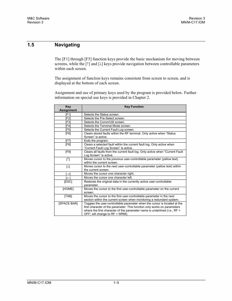
The [F1] through [F5] function keys provide the basic mechanism for moving between screens, while the [↑] and [↓] keys provide navigation between controllable parameters within each screen. The assignment of function keys remains consistent from screen to screen, and is displayed at the bottom of each screen. Assignment and use of primary keys used by the program is provided below. Further information on special use keys is provided in Chapter 2.
Key Assignment
Key Function
[F1] Selects the Status screen. [F2] Selects the Pre-Select screen. [F3] Selects the Comm/Util screen. [F4] Selects the Terminal Mode screen. [F5] Selects the Current Fault Log screen. [F6] Clears stored faults within the RF terminal. Only active when “Status
Screen” is active. [F7] Exits the program. [F8] Clears a selected fault within the current fault log. Only active when
“Current Fault Log Screen” is active. [F9] Clears all faults from the current fault log. Only active when “Current Fault
Log Screen” is active. [↑] Moves cursor to the previous user-controllable parameter (yellow text)
within the current screen. [↓] Moves cursor to the next user-controllable parameter (yellow text) within
the current screen. [→] Moves the cursor one character right. [←] Moves the cursor one character left.
[ESC] Restores the original data in the currently active user-controllable parameter.
[HOME] Moves the cursor to the first user-controllable parameter on the current screen.
[TAB] Moves the cursor to the first user-controllable parameter in the next section within the current screen when monitoring a redundant system.
[SPACE BAR] Toggles the user-controllable parameter when the cursor is located at the first character of the parameter. This function only works on parameters where the first character of the parameter name is underlined (i.e., RF = OFF; will change to RF = WRM).

M&C Software Revision 3 Introduction MN/M-C17.IOM
1–6 MN/M-C17.IOM
1.6 Equipment Type Line
At the very top of each of the first three screens, the system configuration (single RFT or redundant) and screen title are displayed. Directly under this information is the equipment type line. The equipment type line provides two functions:
• Displays the equipment type (i.e., RSU or RFT) and equipment software version information for the current configuration.
• Informs the user when the program has lost communication with the equipment.
In the event of a communication breakdown, a “No Communications” message displayed in red replaces the usual equipment type information. If this happens, the program can no longer perform its prescribed function. Refer to Chapter 3 for instruction on how to re-establish a lost communications link.
Chapter 2 contains more information about operating the M&C software.

MN/M_C17.IOM 2–1
Chapter 2. OPERATION
This chapter provides information regarding the operation of the M&C software when used with single or redundant RFT systems. Note: The screen illustrations provided in this chapter are for reference purposes only. The actual screens that will be displayed on the user’s monitor will vary, depending upon the answers to the seven questions on the Initial Setup screen.
2.1 Getting Started
To start the program:
1. At the DOS prompt, type the appropriate executable (.EXE) file name. 2. Press [ENTER].
At this point, the program queries the user with either one or seven questions, depending on how the first question is answered. These questions provide basic information regarding the type of system being monitored, initial communication parameters, and host computer information required by the program to perform its function. The program stores the user’s response to each question in the program’s “.INI” file, so that the next time the program is started, the user can instruct the program to use the last values entered to initialize the program. Refer to Figure 2-1 for the questions as they are displayed on the host computer’s monitor.

M&C Software Revision 3 Operation MN/M_C17.IOM
2–2 MN/M_C17.IOM
Figure 2-1. Initial Setup Screen Another important feature of the program is the automatic start feature. If, after 30 seconds, no keyboard entries are made in response to initialization questions, the data existing in the program’s “.INI” file is automatically used by the program to initialize. Therefore, by placing the program’s executable (.EXE) file at the end of the user’s AUTOEXEC.BAT file, the program can start and operate in its full capacity without the need for operator intervention. This important feature allows the program to automatically recover from host computer power loss and continue to provide the desired monitoring and logging functions without operator assistance.
M&C Software Revision 3 Operation MN/M_C17.IOM
Rev. Revision 3 MN/M_C17.IOM 2–3
After the program has obtained the initialization data via the keyboard or the program’s “.INI” file, the Version Screen (Figure 2-2) is briefly displayed prior to initiating the Status Screen (Figure 2-3).
Figure 2-2. Version Screen

M&C Software Revision 3 Operation MN/M_C17.IOM
2–4 MN/M_C17.IOM
2.2 Status Screen
The Status Screen (Figure 2-3) provides the operating, maintenance, and fault status information for the Redundant Switch Unit (RSU) (redundant RFT systems only) and the RFTs. Status only parameters (fault and maintenance data) are displayed in white text, except for faults, which are displayed in red. User-controllable operating status parameters are displayed in yellow. Press [F1] to view the Status Screen.
Figure 2-3. Status Screen

M&C Software Revision 3 Operation MN/M_C17.IOM
Rev. Revision 3 MN/M_C17.IOM 2–5
2.2.1 Changing a Parameter
To change a parameter within this screen:
1. Press [↑] or [↓] to move the cursor to the desired parameter. 2. Enter the new data via the alphanumeric keys, or, for selected items, use the
[SPACE BAR] to toggle between valid data choices.
Note: The space bar option is only available on those items where the first character in the parameter name is underlined.
After changes are made to a selected parameter, the text color changes to white. 3. After the desired changes have been made, press [ENTER] to transmit the
command to the selected equipment. If the command is accepted by the equipment, the text color changes back to
yellow. If invalid data was entered, the program displays “ERR” in red text for approximately one second before returning the original data. If this occurs, re-enter the data, making the appropriate corrections, and press [ENTER] again.
If the error message continues, refer to the respective remote control specification
(RSU or RFT) for details regarding the parameter’s valid data. If LOCK MODE was previously enabled (see Section 2.4), the program displays
LOCK in red text for approximately one second before returning the original data. If this occurs, disable the LOCK MODE and re-enter the data.
To cancel a parameter change after the process has begun, press [ESC], and the original data will return.
M&C Software Revision 3 Operation MN/M_C17.IOM
2–6 MN/M_C17.IOM
2.2.2 Presentation of Fault Information
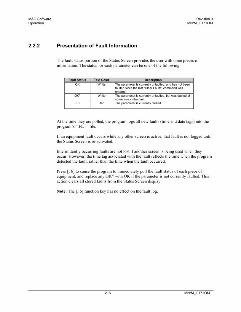
The fault status portion of the Status Screen provides the user with three pieces of information. The status for each parameter can be one of the following:
Fault Status Text Color Description OK
White The parameter is currently unfaulted, and has not been
faulted since the last “Clear Faults” command was entered.
OK*
White The parameter is currently unfaulted, but was faulted at some time in the past.
FLT
Red The parameter is currently faulted.
At the time they are polled, the program logs all new faults (time and date tags) into the program’s “.FLT” file. If an equipment fault occurs while any other screen is active, that fault is not logged until the Status Screen is re-activated. Intermittently occurring faults are not lost if another screen is being used when they occur. However, the time tag associated with the fault reflects the time when the program detected the fault, rather than the time when the fault occurred. Press [F6] to cause the program to immediately poll the fault status of each piece of equipment, and replace any OK* with OK if the parameter is not currently faulted. This action clears all stored faults from the Status Screen display. Note: The [F6] function key has no effect on the fault log.

M&C Software Revision 3 Operation MN/M_C17.IOM
Rev. Revision 3 MN/M_C17.IOM 2–7
2.3 Pre-Select Screen
The Pre-Select Screen (Figure 2-4) provides current values stored within two of the RFT’s three programmable pre-selects. This data is displayed in white text. In addition to data values, this screen provides a user control parameter for programming or clearing each individual pre-select. This control parameter is displayed in yellow text.
Figure 2-4. Pre-Select Screen

M&C Software Revision 3 Operation MN/M_C17.IOM
2–8 MN/M_C17.IOM
2.3.1 Programming a Pre-Select
To program a pre-select with the current frequency and attenuation settings:
1. Press [↑] or [↓] to select the desired pre-select. 2. Perform one of the following steps:
a. Type PROG and press [ENTER]. b. Press the space bar to toggle to PROG, and press [ENTER].
The current frequency and attenuation settings will be displayed in the
appropriate locations on the screen.
2.3.2 Clearing a Pre-Select
To clear a pre-select:
1. Press [↑] or [↓] to select the desired pre-select. 2. Perform one of the following steps:
a. Type CLR and press [ENTER]. b. Press the space bar to toggle to CLR, and press [ENTER].
The frequency and attenuation for the selected pre-select will be removed.

M&C Software Revision 3 Operation MN/M_C17.IOM
Rev. Revision 3 MN/M_C17.IOM 2–9
2.4 Comm/Util Screen
The Comm/Util Screen (Figure 2-5) is divided into two sections:
• Communications Setup • Utility Function
Because all parameters on this screen are user-controllable, all parameters are displayed in yellow.
Figure 2-5. Comm/Util Screen

M&C Software Revision 3 Operation MN/M_C17.IOM
2–10 MN/M_C17.IOM
2.4.1 Communication Setup Sections
The Communication Setup sections display the current address, baud rate, and parity:
• In a single RFT system, for the communication link between the host computer and RFT.
• In a redundant RFT system, for each of the three communication links involved:
The first (left-most) section provides the communication parameters for the link between the host computer and RSU.
The middle and right sections provide the communication parameters for the
links between the RSU and each of the two RFTs.
Each communication link can be independently configured.
Each piece of equipment requires an exclusive address (i.e., no duplicate addresses).
The final parameter in the communication setup section is the user control parameter “Acquire Comm”. As the parameter name indicates, “Acquire Comm” is used to acquire a working communication link between devices when one or all of the link parameters is unknown. “Acquire Comm” initiates a routine that polls the equipment at all combinations of address, baud rate, and parity until a response is received. This routine starts with address 1 and progresses to address 255, while trying the 12 combinations of valid baud rates and parity. Approximately 21 minutes are required for testing all possible combinations until address 255 is reached. This amount of time represents the “worst case” scenario. In most cases, the program establishes the communication link in much less time. However, if the communication link is not functioning due to a hardware or cabling fault, the program will display FAILED after unsuccessfully trying all combinations.
M&C Software Revision 3 Operation MN/M_C17.IOM
Rev. Revision 3 MN/M_C17.IOM 2–11
To command the program to “Acquire Comm”:
1. Press [↑] or [↓] to select the desired link. 2. Perform one of the following steps:
a. Type YES and press [ENTER]. b. Press the space bar to toggle to YES, and press [ENTER].
The program displays a flashing WORKING while polling the link.
2.4.2 Utility Function Sections
The Utility Function sections of this screen provide user control of miscellaneous equipment commands and functions. Included in these functions is control of the LOCK MODE for each piece of equipment. To safeguard equipment from undesired configuration changes (due to accidental or inadvertent keyboard entry), set the LOCK MODE for the equipment to “LK”. When LOCK MODE is set to “LK”, the equipment will not accept configuration change commands, and the program will respond with LOCK in red text when user keyboard entries are made. To enable configuration change commands, set LOCK MODE to “EN”.

M&C Software Revision 3 Operation MN/M_C17.IOM
2–12 MN/M_C17.IOM
2.5 Terminal Mode Screen
The Terminal Mode Screen (Figure 2-6) allows the user to communicate directly with the equipment using the serial interface commands defined in the respective remote control specification for the RSU or RFT.
Figure 2-6. Terminal Mode Screen

M&C Software Revision 3 Operation MN/M_C17.IOM
Rev. Revision 3 MN/M_C17.IOM 2–13
2.5.1 Changing Baud Rate or Parity
The terminal mode screen provides a useful alternative to manual command entry when changing the baud rate or parity. To change the baud rate of the link between the host computer and equipment:
1. Press [ALT] + [B]. 2. Press [↑] or [↓] to select the desired baud rate. 3. Press [ENTER].
To change the data parity:
1. Press [ALT] + [P]. 2. Press [↑] or [↓] to select the desired parity. 3. Press [ENTER].
The program will transmit the appropriate command to the equipment to make the desired change.
2.5.2 Key Definitions/Macros
The program allows storage of up to 10 different keystroke patterns (strings) using the key definitions/macros feature. Frequently-used command strings can be stored and easily retrieved when required. Retrieval is accomplished by pressing [ALT] in conjunction with one of the numeric keys (0 through 9). To use the key definitions/macros feature, press [ALT] + [K], and follow the instructions on the screen. To store the command string to the program’s “.KEY” file for use in future sessions, use the [ALT] + [S] function explained on the display.

M&C Software Revision 3 Operation MN/M_C17.IOM
2–14 MN/M_C17.IOM
This page is intentionally blank.

MN/M_C17.IOM 3–1
Chapter 3. TROUBLESHOOTING
This chapter provides detailed information on how to use the program to troubleshoot communication link problems.
3.1 Verifying Physical Connections
Before the program’s capabilities can be used to help solve communication link problems, it is imperative that all physical connections are verified between the host computer and RFT. Refer to the respective remote control specification for details regarding the RSU or RFT inter-connections. Note: Many host computers provide multiple communication ports. When starting the program, be sure to correctly identify the port number.
3.2 Using the ACQUIRE COMM Feature
After the integrity of all physical connections has been verified, the program’s “Acquire Comm” feature can be used.
1. Select the Comm/Util Screen by pressing [F3]. 2. Press [↑] or [↓] to move the cursor to the “Acquire Comm” command parameter. 3. Either press the space bar to change the parameter from NO to YES, or type in
YES and press [ENTER].

M&C Software Revision 3 Troubleshooting MN/M_C17.IOM
3–2 MN/M_C17.IOM
The program will now display a flashing WORKING while it establishes a working communication link. When the program has determined the proper communication parameters (i.e., address, baud rate, and parity), it will update the parameters accordingly and replace the flashing WORKING with NO. Within a few seconds, the “No Communications” message in the equipment type line will be replaced with the equipment type/software version information. If the program exhausts all combinations of address, baud rate, and parity, and still has not received a response from the equipment, it will replace the flashing WORKING with FAILED. It will take approximately 21 minutes for the program to exhaust all possible combinations. If this happens, recheck all physical connections and repeat the process. If the link still is not established, a hardware failure is likely. Contact the Comtech EFData Customer Service Department for further information.

M&C Software Revision 3 Troubleshooting MN/M_C17.IOM
MN/M_C17.IOM 3–3
3.3 Communication with Redundant Systems
All redundant systems serviced by the program use a branch approach in their system communications (i.e., the user communicates to the system through a single point, the redundant controller, and the single point then provides communication branches to the remaining equipment, the two RFTs). This architecture mandates that the program must first be able to communicate to the redundant controller before it can provide the desired monitor and control functions for the two RFTs. Therefore, when dealing with redundant system communication link problems, the link with the RSU must first be established. After the communication link between the host and RSU has been established, use the appropriate “Acquire Comm” function(s) to establish the links between the RSU and two RFTs.
3.3.1 3.3.1 Addressing
The following are the factory default addresses:
• RSU-503 is set to address 1. • RFT A is set to address 2. • RFT B is set to address 3.
The proper M&C cable hook-up is critical:
• RFT A must be connected to the RSU Port A. • RFT B must be connected to the RSU Port B.
CAUTION
If these connections are reversed, no communications will take place.

M&C Software Revision 3 Troubleshooting MN/M_C17.IOM
3–4 MN/M_C17.IOM
This page is intentionally blank.

METRIC CONVERSIONS
Units of Length
Unit
Centimeter
Inch
Foot
Yard
Mile
Meter
Kilometer
Millimeter
1 centimeter — 0.3937 0.03281 0.01094 6.214 x 10⁻⁶ 0.01 — —
1 inch 2.540 — 0.08333 0.2778 1.578 x 10⁻⁵ 0.254 — 25.4
1 foot 30.480 12.0 — 0.3333 1.893 x 10⁻⁴ 0.3048 — —
1 yard 91.44 36.0 3.0 — 5.679 x 10⁻⁴ 0.9144 — —
1 meter 100.0 39.37 3.281 1.094 6.214 x 10⁻⁴ — — —
1 mile 1.609 x 10⁵ 6.336 x 10⁴ 5.280 x 10³ 1.760 x 10³ — 1.609 x 10³ 1.609 —
1 mm — 0.03937 — — — — — —
1 kilometer — — — — 0.621 — — —
Temperature Conversions
Units of Weight
Unit
Gram
Ounce Avoirdupois
Ounce Troy
Pound Avoir.
Pound Troy
Kilogram
1 gram — 0.03527 0.03215 0.002205 0.002679 0.001
1 oz. avoir. 28.35 — 0.9115 0.0625 0.07595 0.02835
1 oz. troy 31.10 1.097 — 0.06857 0.08333 0.03110
1 lb. avoir. 453.6 16.0 14.58 — 1.215 0.4536
1 lb. Troy 373.2 13.17 12.0 0.8229 — 0.3732
1 kilogram 1.0 x 10³ 35.27 32.15 2.205 2.679 —
Unit
° Fahrenheit
° Centigrade
32° Fahrenheit —
0
(water freezes)
212° Fahrenheit —
100
(water boils)
-459.6° Fahrenheit —
273.1
(absolute 0)
Formulas
C = (F - 32) * 0.555
F = (C * 1.8) + 32

2114 WEST 7TH STREET TEMPE ARIZONA 85281 USA 480 • 333 • 2200 PHONE
480 • 333 • 2161 FAX