mc protocol (ethernet) communications for in-sight … note - mc... · mc protocol (ethernet)...
TRANSCRIPT
MC Protocol (Ethernet) Communications for In-Sight Vision Systems Integration Note
Author: John Keating
Product Marketing Manager
Published: 6 March, 2009
Integration Note
Cognex Corporation Page 2 of 18
Executive Summary This document is intended to assist users to configure Ethernet based MC Protocol communications between In-Sight vision systems and Mitsubishi Q-Series PLCs. MC Protocol communication enables In-Sight vision systems to communicate directly with Mitsubishi PLCs without requiring ladder logic. Examples in this document are based on In-Sight Explorer software version 4.3, using the EasyBuilder interface, and Mitsubishi’s GX Developer software, version 8.
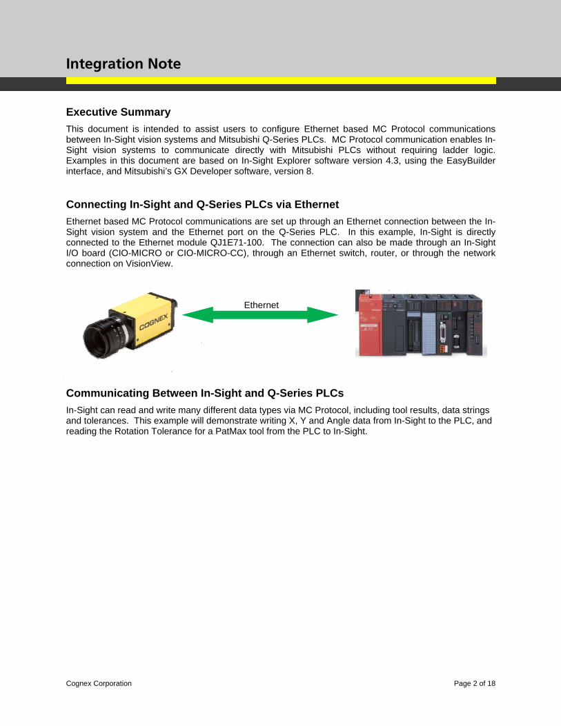
Connecting In-Sight and Q-Series PLCs via Ethernet Ethernet based MC Protocol communications are set up through an Ethernet connection between the In-Sight vision system and the Ethernet port on the Q-Series PLC. In this example, In-Sight is directly connected to the Ethernet module QJ1E71-100. The connection can also be made through an In-Sight I/O board (CIO-MICRO or CIO-MICRO-CC), through an Ethernet switch, router, or through the network connection on VisionView.
Communicating Between In-Sight and Q-Series PLCs In-Sight can read and write many different data types via MC Protocol, including tool results, data strings and tolerances. This example will demonstrate writing X, Y and Angle data from In-Sight to the PLC, and reading the Rotation Tolerance for a PatMax tool from the PLC to In-Sight.
Ethernet
Integration Note
Cognex Corporation Page 3 of 18
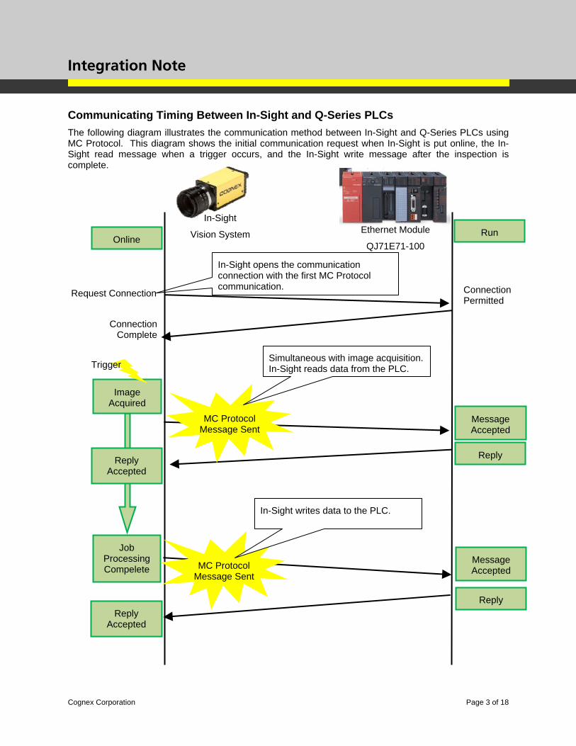
Communicating Timing Between In-Sight and Q-Series PLCs The following diagram illustrates the communication method between In-Sight and Q-Series PLCs using MC Protocol. This diagram shows the initial communication request when In-Sight is put online, the In-Sight read message when a trigger occurs, and the In-Sight write message after the inspection is complete.
Message Accepted
Run Online
Image Acquired
Trigger
Job Processing Compelete
Reply
Request Connection Connection Permitted
Connection Complete
Reply Accepted
In-Sight opens the communication connection with the first MC Protocol communication.
Ethernet Module
QJ71E71-100
In-Sight
Vision System
Message Accepted
Reply
MC Protocol Message Sent
Simultaneous with image acquisition. In-Sight reads data from the PLC.
MC Protocol Message Sent
Reply Accepted
In-Sight writes data to the PLC.
Integration Note
Cognex Corporation Page 4 of 18
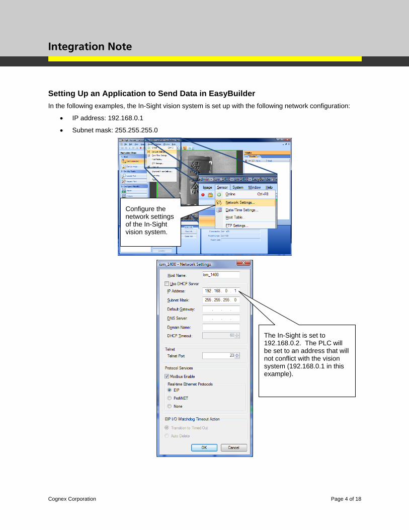
Setting Up an Application to Send Data in EasyBuilder In the following examples, the In-Sight vision system is set up with the following network configuration:
• IP address: 192.168.0.1
• Subnet mask: 255.255.255.0
The In-Sight is set to 192.168.0.2. The PLC will be set to an address that will not conflict with the vision system (192.168.0.1 in this example).
Configure the network settings of the In-Sight vision system.
Integration Note
Cognex Corporation Page 5 of 18
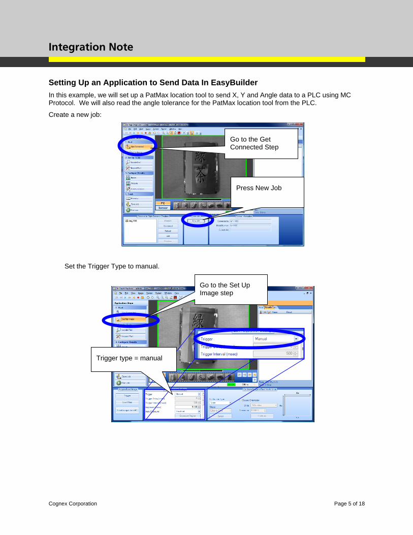
Setting Up an Application to Send Data In EasyBuilder In this example, we will set up a PatMax location tool to send X, Y and Angle data to a PLC using MC Protocol. We will also read the angle tolerance for the PatMax location tool from the PLC.
Create a new job:
Set the Trigger Type to manual.
Go to the Get Connected Step
Press New Job
Go to the Set Up Image step
Trigger type = manual
Integration Note
Cognex Corporation Page 6 of 18
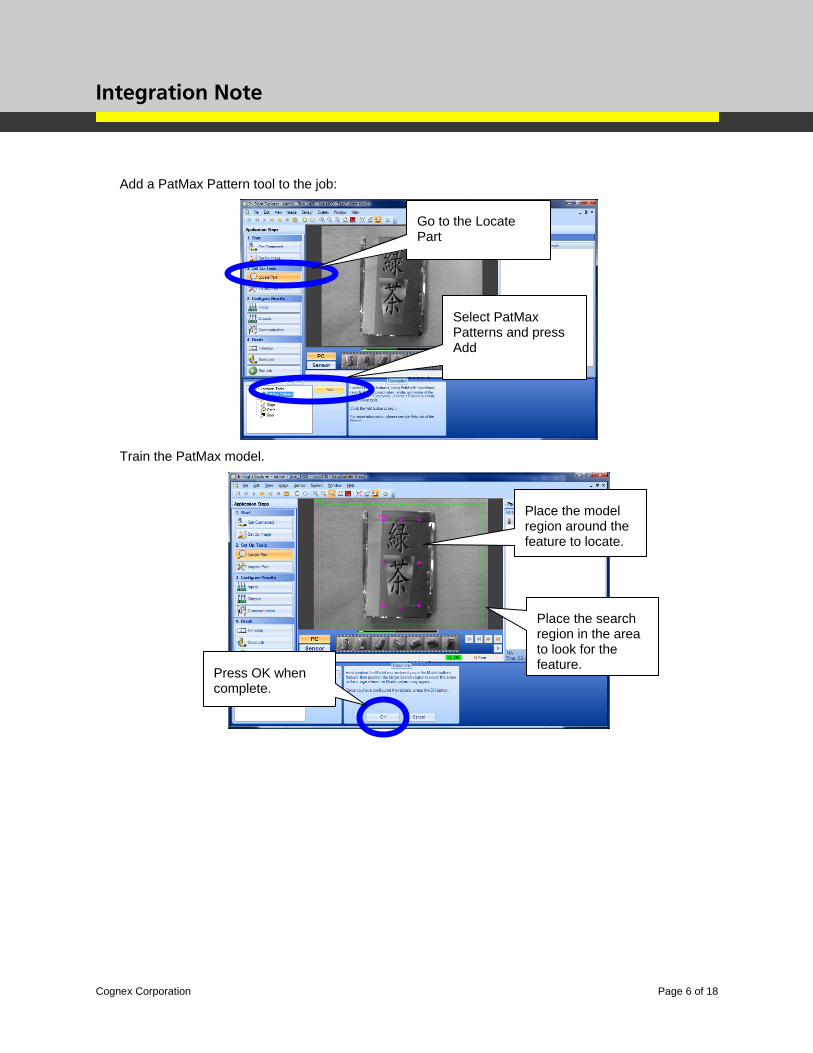
Add a PatMax Pattern tool to the job:
Train the PatMax model.
Select PatMax Patterns and press Add
Go to the Locate Part
Place the model region around the feature to locate.
Place the search region in the area to look for the feature. Press OK when
complete.
Integration Note
Cognex Corporation Page 7 of 18
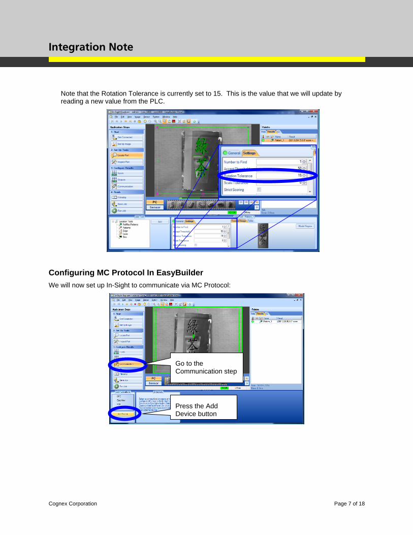
Note that the Rotation Tolerance is currently set to 15. This is the value that we will update by reading a new value from the PLC.
Configuring MC Protocol In EasyBuilder We will now set up In-Sight to communicate via MC Protocol:
Press the Add Device button
Go to the Communication step
Integration Note
Cognex Corporation Page 8 of 18
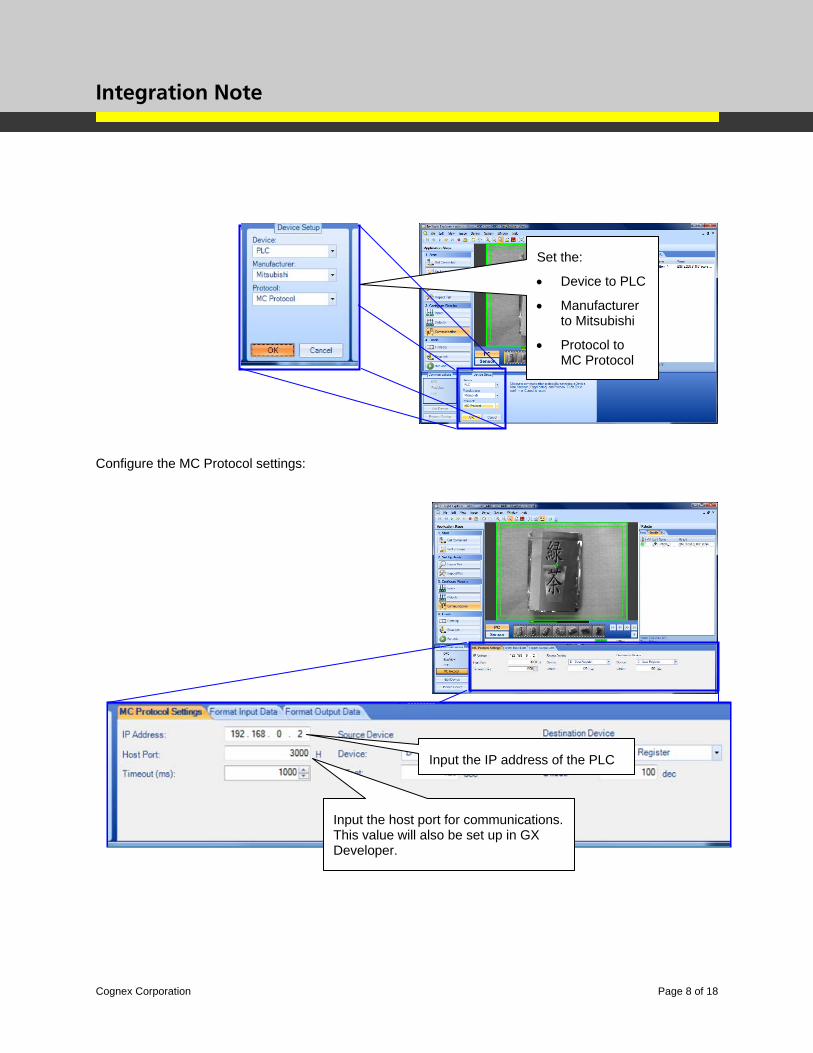
Configure the MC Protocol settings:
Set the:
• Device to PLC
• Manufacturer to Mitsubishi
• Protocol to MC Protocol
Input the host port for communications. This value will also be set up in GX Developer.
Input the IP address of the PLC
Integration Note
Cognex Corporation Page 9 of 18
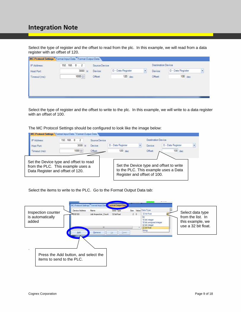
Select the type of register and the offset to read from the plc. In this example, we will read from a data register with an offset of 120.
Select the type of register and the offset to write to the plc. In this example, we will write to a data register with an offset of 100.
The MC Protocol Settings should be configured to look like the image below:
Select the items to write to the PLC. Go to the Format Output Data tab:
.
Inspection counter is automatically added
Select data type from the list. In this example, we use a 32 bit float.
Set the Device type and offset to read from the PLC. This example uses a Data Register and offset of 120.
Set the Device type and offset to write to the PLC. This example uses a Data Register and offset of 100.
Press the Add button, and select the items to send to the PLC.
Integration Note
Cognex Corporation Page 10 of 18
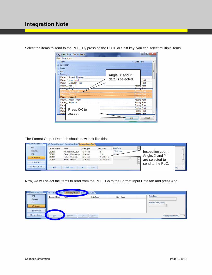
Select the items to send to the PLC. By pressing the CRTL or Shift key, you can select multiple items.
The Format Output Data tab should now look like this:
Now, we will select the items to read from the PLC. Go to the Format Input Data tab and press Add:
Inspection count, Angle, X and Y are selected to send to the PLC.
Angle, X and Y data is selected.
Press OK to accept.
Integration Note
Cognex Corporation Page 11 of 18
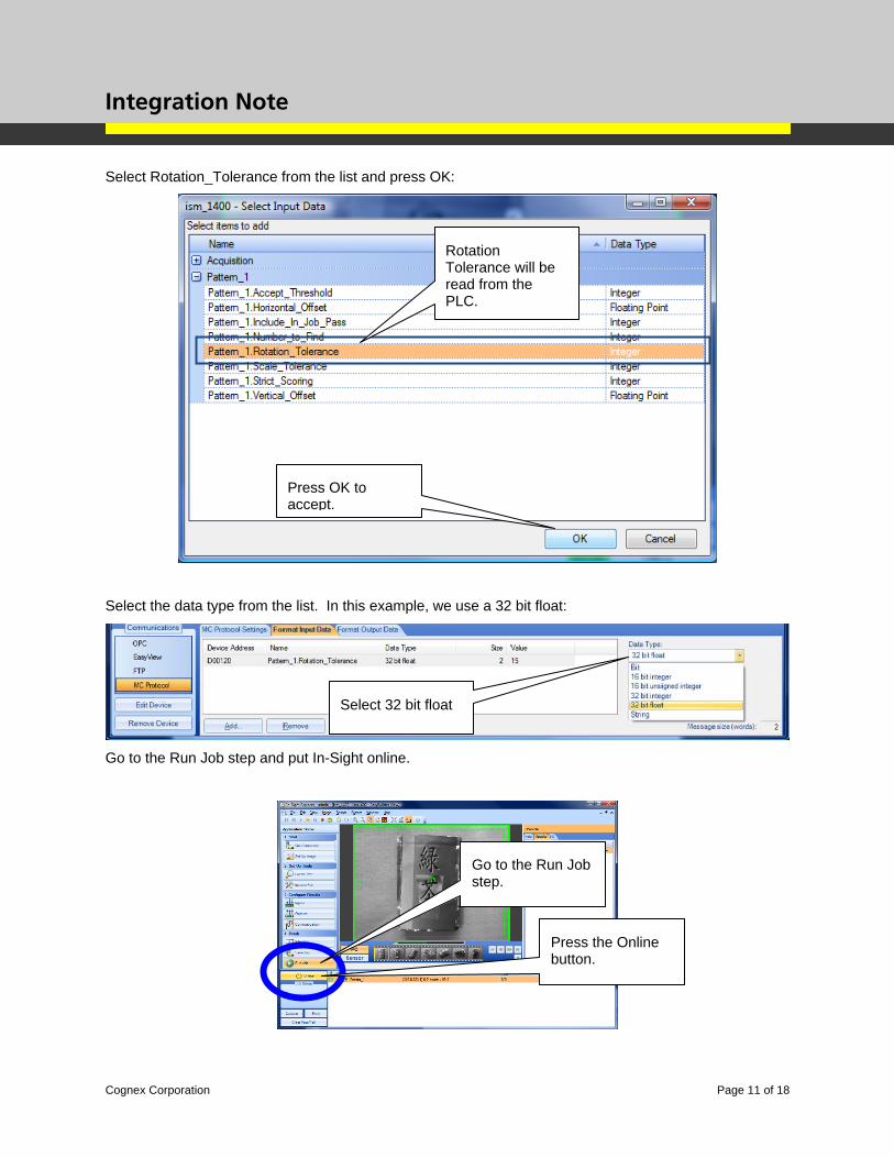
Select Rotation_Tolerance from the list and press OK:
Select the data type from the list. In this example, we use a 32 bit float:
Go to the Run Job step and put In-Sight online.
Rotation Tolerance will be read from the PLC.
Press OK to accept.
Select 32 bit float
Press the Online button.
Go to the Run Job step.
Integration Note
Cognex Corporation Page 12 of 18
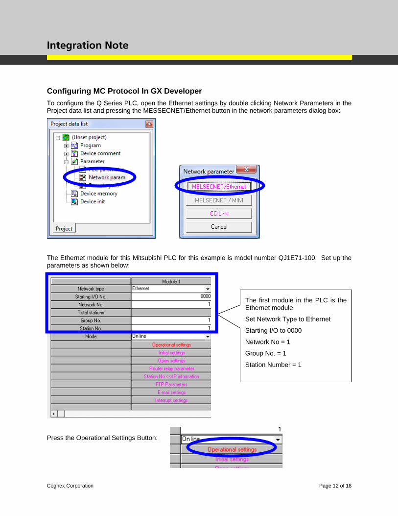
Configuring MC Protocol In GX Developer To configure the Q Series PLC, open the Ethernet settings by double clicking Network Parameters in the Project data list and pressing the MESSECNET/Ethernet button in the network parameters dialog box:
The Ethernet module for this Mitsubishi PLC for this example is model number QJ1E71-100. Set up the parameters as shown below:
Press the Operational Settings Button:
The first module in the PLC is the Ethernet module
Set Network Type to Ethernet
Starting I/O to 0000
Network No = 1
Group No. = 1
Station Number = 1
Integration Note
Cognex Corporation Page 13 of 18
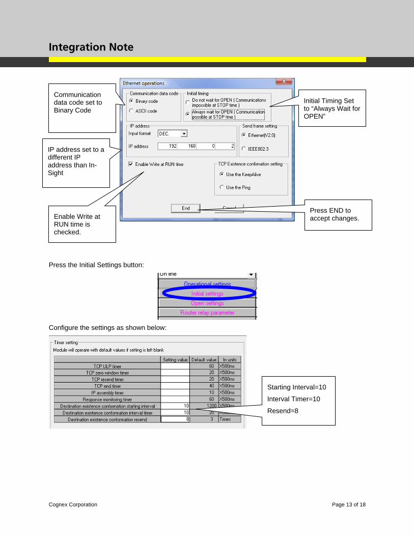
Press the Initial Settings button:
Configure the settings as shown below:
IP address set to a different IP address than In-Sight
Communication data code set to Binary Code
Initial Timing Set to “Always Wait for OPEN”
Enable Write at RUN time is checked.
Press END to accept changes.
Starting Interval=10
Interval Timer=10
Resend=8
Integration Note
Cognex Corporation Page 14 of 18
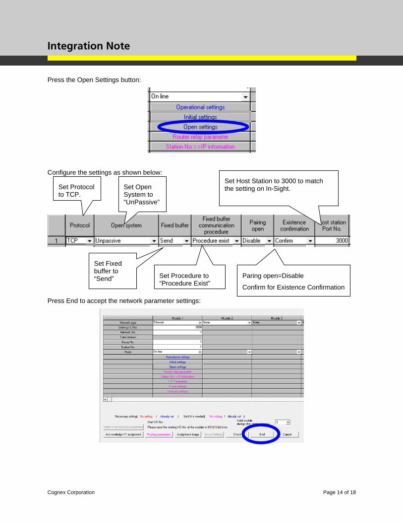
Press the Open Settings button:
Configure the settings as shown below:
Press End to accept the network parameter settings:
Set Protocol to TCP.
Set Open System to “UnPassive”
Set Fixed buffer to “Send” Set Procedure to
“Procedure Exist”Paring open=Disable
Confirm for Existence Confirmation
Set Host Station to 3000 to match the setting on In-Sight.
Integration Note
Cognex Corporation Page 15 of 18
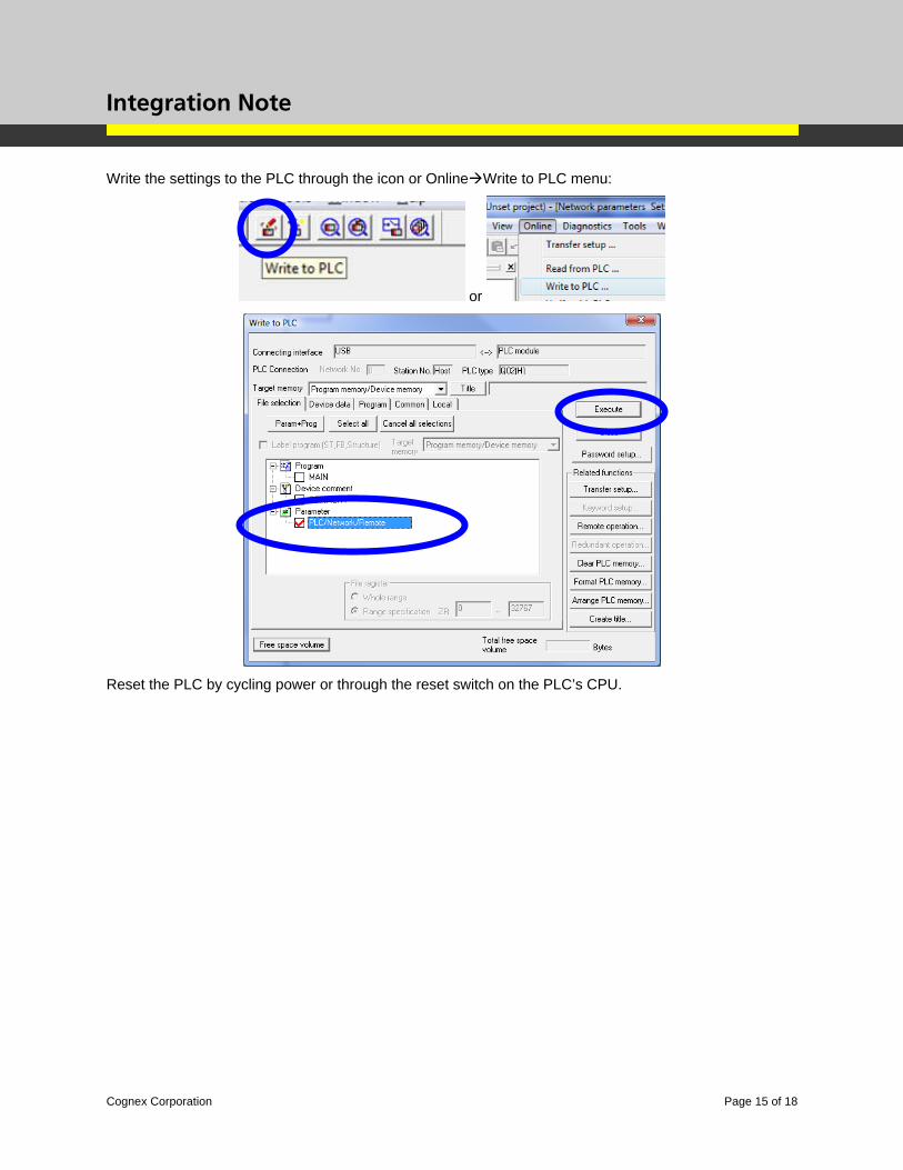
Write the settings to the PLC through the icon or Online Write to PLC menu:
or
Reset the PLC by cycling power or through the reset switch on the PLC’s CPU.
Integration Note
Cognex Corporation Page 16 of 18
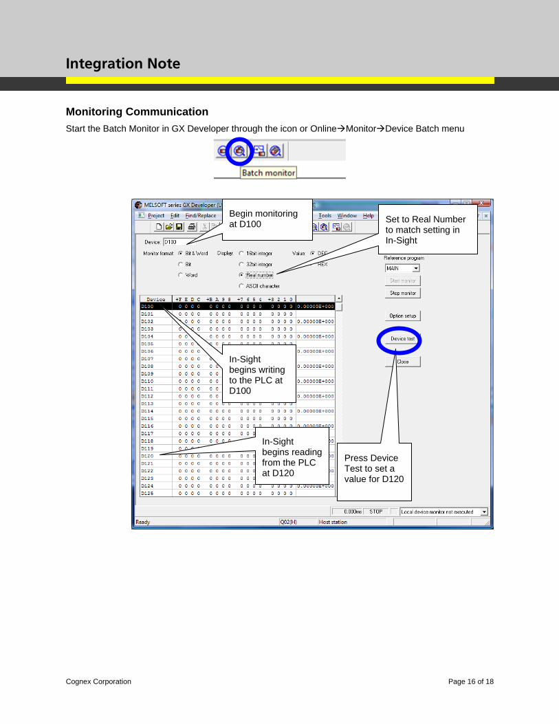
Monitoring Communication Start the Batch Monitor in GX Developer through the icon or Online Monitor Device Batch menu
Begin monitoring at D100
In-Sight begins reading from the PLC at D120
In-Sight begins writing to the PLC at D100
Press Device Test to set a value for D120
Set to Real Number to match setting in In-Sight
Integration Note
Cognex Corporation Page 17 of 18
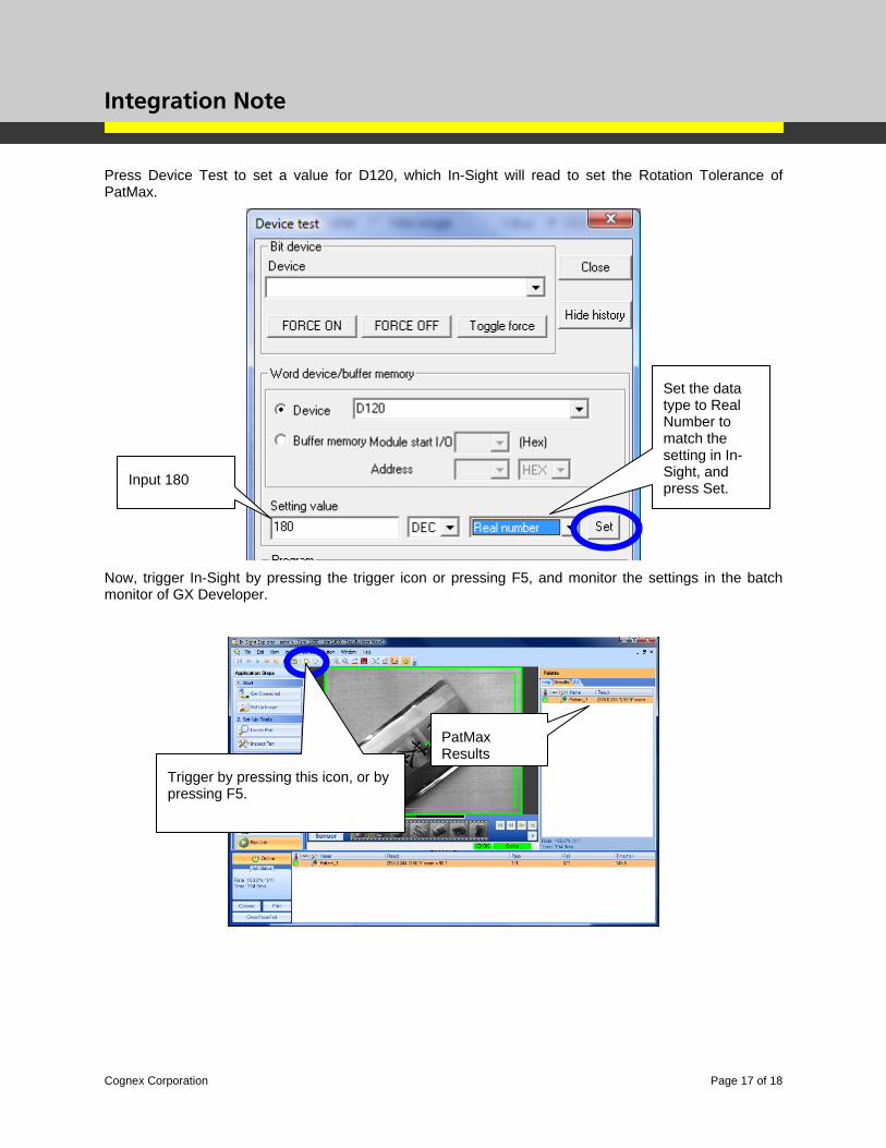
Press Device Test to set a value for D120, which In-Sight will read to set the Rotation Tolerance of PatMax.
Now, trigger In-Sight by pressing the trigger icon or pressing F5, and monitor the settings in the batch monitor of GX Developer.
Input 180
Set the data type to Real Number to match the setting in In-Sight, and press Set.
Trigger by pressing this icon, or by pressing F5.
PatMax Results
Integration Note
Cognex Corporation Page 18 of 18
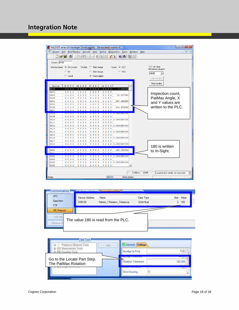
Inspection count, PatMax Angle, X and Y values are written to the PLC.
180 is written to In-Sight.
The value 180 is read from the PLC.
Go to the Locate Part Step. The PatMax Rotation