mc 140x - soundstream | mobile car audio/video, … a/mc140245...mc140” - sekting operating mode...
TRANSCRIPT

MC 140xMulti-Channel 140 Watt Amplifierwith Staggered Electronic Crossover
MC245Khannel 240 Watt AmplifierWith Staggered Electronic Crossover
OWER’S MANUAL
T E C H N 0 L 0 G I E S

MC140xMulti-Channel
140 Walt Am lifier with
StaggetJEktronicCrossover Network
MC245S-Channel
240 Wait Am lifier with
s&HeJEktronicCrossover Network
OM(NER’S MANUAL
Thank you for purchasing the Soundstream MC140” or MC245 You now own one of thefinest amplifier/electronic crossover combinations made, a precision component capable
of audiophile quality performance.
To get the most out of your unit, we suggest that you acquaint yourself with its capabilitiesand design. Please retain this manual for future reference.
.
Model Number:
Serial Number:
Dealer’s Name:
This Soundstream Product is the result of American craftsmanship and the highest quality
control standards; your amplifier/electronic crossover will deliver many years of pleasure.
Should it ever require service or replacement, recording the information below for your ownrecords will help protect your investment.
Date of Purchase:
Date of Install:

DESIGN FEATURES The MC140x is conservatively rated at 140 watts. This power can be divided into: Four
channels (4 x 35 watts), Three channels (2 x 35 watts, 1 x 90 watts), Two channels (2 x 90watts).
The MC245 is conservatively rated at 240 watts. This power can be divided into; Five
channels (4 x 35 watts, plus 1 x 100 watts), Four channels (2 x 35 watts, plus 1 x 90 watts,
plus 1 x 100 watts), Three channels (2 x 90 watts, plus 1 x 100 watts).
The design topology of both amplifiers utilize multiple Darlington output devices with a totaloutput capability five times the total rated output of the amplifier. With such reserves and nocurrent limiting, both amplifiers operate without strain even at maximum output. Power,
ground, and speaker connectors are rated to handle up to 80 amps and accommodate upto 8 gauge stranded cable. To prevent potentially damaging turn-on and turn-off thumps, abuilt-in delay circuit allows these amplifiers to fully stabilize before sending the audio signal
to the loudspeakers.
The MC 140x/245 provide superior, non-intrusive protection from overheating in two ways:First, the Soundstream “Chassisink” has been custom designed to guarantee the lowest
_ possible thermal resistance (maximum cooling), greatly reducing the possibility of over-
heating. Secondly, if this should occur, all Soundstream amplifiers incorporate our “SmartPower Supply” which temporarily modifies the power supply’s operating parameters,
allowing the amplifier to run much cooler. Full output capability is restored once theamplifier returns to normal operating temperature. This entire process is automatic and
inaudible.
In the case of an actual amplifier malfunction, secondary fuses will shut down these
amplifiers in a conventional manner. Only premium parts are used, such as 1% metal filmresistors, gold-plated input connectors, double-sided masked glass epoxy circuit boardsand immersible sealed potentiometers. Input sensitivity is adiustoble to match any tuner/
deck, these amplifiers can even be interfaced with most OEM speaker level signals. Both theMC140” and MC245 incorporate built-in Staggered Asymmetrical Electronic Crossover.
The high pass crossovers are set at 18OHz with a slope of 6dB per octave. The low passcrossovers are set at 75Hz with a slope rate of 12dB per octave. By selecting two staggeredfrequencies, a dip in the acoustic response is created, which is most useful to compensate forcommon vehicle response peaks between these two fixed points.
INSTALLATION Proper installation and adiustment will reward you with reliable operation and optimum
performance. Automotive sound system installations can be tricky, especially for first-timers.For this reason, you may want to consider using a professional installer who has the tools
and more importantly, the experience to do the job right.
of you decide to install your equipment yourself, we hope this manual will sewe as a helpful
guide.
Making Terminations at the AmplifierThe only tool needed to make wire terminations at the amplifier will be an insulated flat
blade screwdriver. Do not use a non-insulated screwdriver since this may short against the
heat sink and damage the amplifier. The screwdriver used should be one with a long
enough shank to allow clearance between the fins of the heat sink. Moreover, this will
prevent unwanted damage or scraping.
bcation and MountingmThe first step in an installation is thorough planning. Choose the location for your amplifiercarefvlly. The amplifier should be located in either the passenger compartment or the trunk,
never in the engine compartment or in any outside location exposed to dirt and moisture.Adequate ventilation is important; allow enough space so that air can circulate around the
, heat sinks. Make sure that the installed amplifier will not interfere with normal operation of
the vehicle. It is best not to locate an amplifier near your vehicle antenna, since the switchingpower supply can interfere with AM reception. Your amplifier should be mounted to yourvehicle’s chassis with the four screws provided. Use you amplifier as a template for making
pencil marks where you intend to drill. (Make sure the location you are planning to drillthrough is free of any obstacles such as factory vehicle wiring or gas tanks.) It’s a good idea
to bench test your system before mounting the components. If you have a 12 volt powersource, you can connect and test all components outside the vehicle. Or, you can connect
them inside the vehicle prior to final mounting. Either way, connect aII components exactlythe way you intend to in the system to ensure proper installation; then disconnect all powerconnections until the installation is complete.
WringDetermine how your vehicles wiring is laid out. Keep all wiring inside the vehicle. Good
standard audio practice suggests keeping all low level wiring away from wires carrying
twelve volts. If you drill a new hole through any metal, be sure to install a grommet to preventshorting. It is a good idea to paint the bare metal to prevent rust. All wires should behidden under carpet; an exposed wire can inadvertently be pulled, causing disconnectionor shorting. Wires should never be under tension or subject to moisture. Use cable ties to
bundle excess wire.
Amplifier Configuration DiagmmsIn the last nine pages of this manual you will find several system configuration diagrams.
Please review the pages appropriate to the amplifier model you have purchased. Both these
Soundstream amplifiers offer a variety of available configurations. Please use the configu-ration that best suits your installation needs.
MC140” - Sekting Operating ModeThe 140 watts available from the MC 140x can be divided into two channels (stereo) threechannels (stereo plus a single mono channel) or four channels (front and rear stereo; or
stereo bi-amp).
To select any of these modes, remove the access hatch on the bottom of the amplifier and setthe internal switches marked stereo/mono to the desired mode of operation. (Do not closethe access hatch if you are going to be using the internal electronic crossover capabilities OFthis amplifier.)
For two channel operation, set both internal switches to the mano position.
For three channel operation, set one switch to mono operation and the other to stereo.
For four channel operation, leave both switches in the stereo position.
MC140” - Internal Ektronic CrossoverYour MC140” is equipped with a Staggered Asymmetrical Electronic Crossover. Based onthe selected operating mode, you can operate a pair of satellites and a pair of subwoofers
in the four channel mode, or a pair of satellites and a mono subwoofer in three channelmode. The crossover points are preset as follows; High pass is set at 18OHz permitting only
frequencies of l80Hz and higher to be passed on to the satellib. Low pass is set at 90Hzpermitting only frequencies of 90Hz and lower to be passed on to your subwoofer( The
net result is an effective Two-way Staggered Asymmetrical Crossover. To set up theelectronic crossover for your system, again go to the access area on the bottom of the
amplifier. Right next to the Stereo/Mono switches, you will find he crossover switches. Theyare labeled Full Range/High Pass, and Full Range/Low Pass. When using the on-board
crossover, the satellite speakers must be connected to the outputs labeled Channels Z/4,and your subwoofers should be connected to the outputs labeledChannels l/2. This is howthe crossover is configured. For a visual reference, please consult the Amplifier Configuru-tion &grams at the end of this manual.
MC245 - Selecting Operating ModeThe 240 watts available from the MC245 can be divided into three channels (stereo plus a
single mono channel), four channels (stereo plus two mono channels), and five channels(front and rear stereo plus a single mono channel). To select any of these modes, remove theaccess plugs labeled stereo/mono on the bottom of the amplifier and set the switches to the
desired setting.
For five channel operation, set both switches to the stereo position.
For four channel operation, set one switch to mono operation, and the other-to stereo.
For three channel operation, set both switches to the mono.
MC245 - Internal Ektronic CrossoverYour MC245 is equipped with a Staggered Asymmetrical Crossuver. Based on the selectedoperating mode, you can operate two pairs of satellites and one to four subwoofers in five
channel mode, one pair of satellites, a center channel, and one )O four subwoofers in four
channel mode, or one pair of satellites and one to four subwoof& in three channel mode.To set up the electronic crossover for your system, again go to theaccess plugs on the bottomof the amplifier and locate those marked; Full Range/High Passand Full Range/Low Pass.
4
When using the on-board crossover, the satellite speakers must be connected to the outputslabeled Channels I, 2,3,4, and the subwoofers must be connected to the outputs labeled
Mono Subwoofer Channel. This is how the crossovers are configured. For a visual referenceas to how all selections should be made for your application, please consult the Amplifier
Configuration Diagrams at the end of this manual. ;
MC140” - input ConnectionsInputs to your amplifier attach by means of standard RCA type iacks. When using theamplifier in the stereo mode, use both the left and right input iacks. When using a portion of
the amplifier in bridged mode, use only the right input jack for the side of the amplifier that
is to be bridged.
Your MC140” has also been equipped with a unique feature that allows you to use just the
Channels S/4 input and distribute the signal to all four channels of the amplifier. This isaccomplished by using the switch labeled /ntemu/Audio /nput/Extemu/ Audio Input. This
switch is located with the crossover and bridging switches behind the access hatch on hebottom of the amplifier. When set to the Externalposition, the amplifier must receive input onboth the Channel I/2 and Channel S/4 side. When set to the Internal position you need
only use inputs on the Channel S/4 side of the amplifier. The major benefit of this switch istwofold, you can use it when you are interfacing with a head unit equipped with only one set
of pt-eamp outputs, and when you are using the full crossover capability of the amplifier in a
full bi-amp system, where there is no need to have head unit fading capability.
-
MC245 - Input ConnectionsInputs to your amplifier connect by means of standard RCA type iacks. When usingChannels l/2 and Channels S/4 in stereo you must use all four of the left and right inputs.
When using either pair of amplifiers bridged, only the right input is to be used for that pair.
Your MC245 has also been equipped with optional separate subwoofer inputs. You can useeither or both of the inputs since this is a paralleled mono input. You can also feed thisamplifier a stereo signal and it will automatically sum it into a mono signal.
If you plan to use the external subwoofer inputs for your particular application, it will be
necessary for you to first locate the switch labeled Memo/ Audio Input/&emu/ Audio/nput located behind an access plug or hatch on the bottom of the amplifier. Set the switch tothe External position, this will activate the external inputs. If you are going to use just the fourinputs, set the switch to the Memu/ position. This will automatically distribute signal to the
subwoofer portion of the amplifier. Please consult the Amplifier Configurution Diagrams forthe application that best suits your needs.
General Guidelines - Input ConnectionsFor connection from your head unit to the amplifier(s), we recommend the use ofSoundstream DL.1 or an equivalent premium cable. In most cases, the signal source will be
the preamp output jacks of a head unit. However, some head units use preamp outputconnectors other than the RCA type. In this case you will need a special adapter to convertfrom the source configuration to RCA. This adapter should be available from the dealer whosold you your head unit. If your head unit has speaker outputs but no preamp outputs, yourSoundstream amplifier has been equipped with “Adapter-free” interface capability. Thisallows you to wire an RCA connector directly to the end of your head units speaker wires.
However, before doing so, determine if your head unit has standard or BTL type output. A
5

good rule of thumb is that any head unit producing 5 or more true watts a channel is BTL.
Once you determine the type of output your head unit has, follow the appropriate diagrambelow for hookup.
If you have an equalizer or low level crossover network(s), these components will be inserted
between your head unit and the amplifier(s). Refer to the manuals of those items for the
proper connection.
/ \
5+ Spkr Out
6
f-J-=3g@-&G”,
eg?
- Spkr Out
O- l-l
5?
- Spkr Out: no corm.
\ / STANDARD BTL
Output ConnectionsUse Soundstream High Definition speaker cable (such as Speaker 120 or 160) or anequivalent for best results. The terminals of your loudspeakers are marked for polarity, and
the speaker wire should be coded by color or markings on the iacket. Be sure to connect theieft and right hc annels with the same polarity. Loudspeaker manufacturers are not veryconsistent in their polarity markings, so if you have loudspeakers of different typesconnected to the same amplifier terminal, verify correct polarity by ear. Correct polarityproduces the most bass response while incorrect produces less bass and a strangely
dislocated image on mono material. For your specific hookup, please carefully review thelmpedunce Hookup Diagrams that follow, as well as the Amp/%er Configuration Diagramsat the end of this manual.
Impedance Hookup Diagrams
SERIES PARALLEL
Power Connections
004R
i
+ --
~ 004Q+ -
2Riis+ -
00451
SERIES + -
Your amplifier can only be operated from 12 volt negative ground electrical system. If yourcar was produced before 1970, or if you have any doubts, make sure of the type of electrical
system your car has prior to attempting installation.
The MC 1 40x may draw up to 20 amperes and the MC245 may draw up to 30 amperes, if
6

they are used to their full output capability. Determine the alternator rating of your car tomake sure your charging system is capable of delivering the necessary current to operatethese products. If either one of these amplifiers is being used without any additional
amplifiers, odds are you have more than enough current. If these amplifiers are part of a
multi-amplifier system, investigate your potential current consumption. It may be necessary
for you to add a second battery or upgrade the existing alternator.
For Power, Ground and Remote connections, we recommend Soundstream premium cable(such as Power 80 or loo), or an equivalent. A minimum of 10 gauge power and ground
cable should be used on both of these amplifiers in order to realize maximum performance.An in-line fuse should also be installed under the hood approximately 12 inches from the
battery. For the MC140X a 20 amp fuse should be installed, and for the MC245 a 30 amp
should be installed
Remote Power-on Connection
If your head unit has a remote power-on control wire, connect it to the remote terminal on
your amplifier. This is a control line, not a power line, so a small gauge wire, such as_Soundstream Remote 200 Sensing cable is ideal for this connection.
If your head unit has no remote power-on control labeled as such, look for a power antenna
control, this may be used instead. If your head unit has neither a remote power-on controlwire or a usable power antenna control, it will be necessary either to connect the remoteterminal to a 12 volt source which is switched by the ignition key, or to connect a 12 volt sourcethrough an on/off switch you install in series with the ignition switch in a location accessible
to the driver.
NOTE: If an o&oar-d switch is used, make sure it is in the OFF position whenever you leave
the vehicle. this will prevent extended drain on the battev.
Before Powering Up he System
To prevent unnecessary labor and damage to your components, be sure to proof yoursystem and all of its connections prior to attempted operation. Also double-check to see thatyou have selected all of the correct amplifier settings.
Powering Up he System
Once all connections have been checked, turn on the system. Be sure to keep the volumelow. You should be hearing music at this point. If not, turn off the system immediately andagain check for shorts and poor connections. If all wiring is in order, check the fuse installedat the battery and then the speaker output fuses located on the bottom of the amplifier. If any
of these are blown, replace them with the same value only.
Input Level Adjustments
Input levels are adiusted by means of independent controls located directly above the inputs,b twe een e ea sin s ins. 0 se yth h t ’ k f’ T t our amplifier levels, begin by turning all level controls tominimum (full counter-clockwise). Turn the system on, and set the volume on your head unitat its mid-point. Advance the amplifier input level controls until you have reached acomfortable listening level and all channels are balanced.
NOTE: W;th many head units, the radio output /eve/ is significant/y difkent than that of the
other source. Check both sources and set levels using the lesser of the outputs.
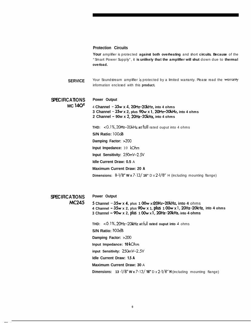
Protection Circuits
Your amplifier is protected against both overheating and short circuits. Because of the“Smart Power Supply”, it is unlikely that the amplifier will shut down due to thermaloverload.
SERVICE Your Soundstream amplifier is protected by a limited warranty. Please read the warran?/
information enclosed with this product.
SPECIFICATIONS Power Output
MC 140x 4 Channel - 35~ x 4,20Hz-2OkHz, into 4 ohms3 Channel - 35~ x 2, plus 9&v x 1,2OHz=20kHz, into 4 ohms2 Channel - 90w x 2,2OHz-2OkHz, into 4 ohms
THD: <O.l%, 20Hz-20kHz at full rated ouput into 4 ohms
S/N Ratio: 1OOdB
Damping Factor: >200
Input Impedance: 10 kOhm
Input Sensitivity: 250mV-2.5V
Idle Current Draw: 0.5 A
Maximum Current Draw: 20 A
Dimensions: 8-l/8” W x 7- 13/ 16” D x 2-l/8” H (including mounting flange)
SPECIFICATIONS Power Output
MC245 5 Channel - Xw x 4, plus 1 OOw x 20Hz-2OkHz, into 4 ohmsI ,4 Channel - 35~ x 2, plus 9Ow x 1, plus 1 OOw x 1,20Hz-20kHz, into 4 ohms3 Channel - 9Ow x 2, plus 1 OOw x 1,20Hz-20kHz, into 4 ohms
THD: ~0.1%~ 20Hz-20kHz at fuII rated ouput into 4 ohms
S/N Ratio: 1OOdB
Damping Factor: >200
Input Impedance: 10 kOhm
input Sensitivity: 250mV-29
Idle Current Draw: 1.5 A
Maximum Current Draw: 30 A
Dimensions: 13 -l/8” W x 7- 13/ 16” D x 2-l/8” H (including mounting flange)
8

AMPLIFIER CONFlGiJRATiON DIAGRAM # I
MC245S-Channel Using Internal Crossovers
Front Panel Connections
MC 245multiDk ChOnne( two h u n d r e d for& watt
SOUNDSTIWM’ Manutocturod In U 5 A
4 ., 1pow& amplifier / ekctronlc cro&er
MONO SUBWOOFER CHANNEL CHANNELS 1 and 2 CHANNELf 3 and 4
I OUTPUT CONNECTORS INPUT CONNECTORS OUTPUT CONNECTORSONE TWO
I I ILEfl SRAKER I)IGHl SPEAKER
+ - - + ONE TWO + - - + I INPUT CONNECTORS I OUTPUT CONNECTO@LEFr SPEANC2 RIGHT SPEAKER
LEFI I)IGHT + - - + I INPUT CONNECTORS
LEFT PfGHl I
t0Remote
to ChassisGroundII r 0 li
800
Sate1
i?0
%00
lites
0 1180
0Sate
r0
%00
kites
:
.
I r.
p
0
1 Fuse
p
0to +12vBatteryTerminal
I-180 Hz 6 dS/Oct 180 Hz 6 db/Oct
Subwoofers
I\ 75 Hz 12dB/Oct
Bottom Panel Switch Settings
Head Unit
@4 3 02 1
Subwoofer Channel5A fuse
Channel Channel3A fuse 3A fuse
full range Mono
internalaudioinput full rangefull range Mono
lL!--aI I1 I
high pass Stereo
I ’180 Hz 6 dB/Oct ’
externalaudioinput
high pass
I-
Stereo
180 Hz 6 dS/Oct 75 Hz 12dWOct
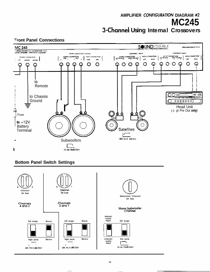
AMPLIFIER COlVFlGUUATlOlV DIAGRAM #2
MC245a-Channel Using Internal Crossovers
=r0nt Panel Connections
7uMpk chcmnol two hundred tofly wattaowef omplifler / ekctromc crosovof MONO SUBWOOFER CHANNEL
POWER CONNECTORS INPUT CONNECTORS
t0
Remote
to ChassisGroundW-mI
rI r I II Head Unit
0 AA80
0Sat
(1 pr Pre Out only)
’ 00ellites
f
Fuse
to +12vBatteryTerminal
5
i
.
H0fl0100 Hz 6 dB/OctSubwoofers
I75 Hz 12dB/Oct
Bottom Panel Switch Settings
@A 3
Channel3A fuse
Subwooter Channel5A fuse
internalaudioinput full rangefull range Monofull range Mono
I
high pass Stereo
I ’180 Hz 6 dB/Oct
I I
high pass Stereo
I ’180 Hz 6 dB/Oct
externalaudioinput
low pass
I-
75 Hz 12dB/Oct
10

AMPLIFIER CONFIGURATION DlAGRAM #3
MC245S-Channel Tri-Amp Using Internal and 2-way External Crossovers
Front Panel Connections
MC 245 SOUNDSTl’?E”!‘v’I’ Manufactured in U.S.A.
multtple channel two hundred forty wattpower amplifier / electronic crossover
I
POWER CONNECTORS
I+l2v ground remoto
L . 4 1 / L’MONO SUBWOOFER CHANNEL CHANNELS I and 2 CHANNELS 3 ond 4
I
OUTPUT CONNECTORS
I
INPUT CONNECTORS I I OUTPUT CONNECTORS I INPUT CONNECTORS 3UTWl CONNECTORS ; INPUT CO+dNklORSONE TWO LEFl SPEAKER RIGHT SPEAKER LEE WEAKER QfGWr SPEAKER
+ - - + ONE TWO + - - + LEFI RtGHl I + - - + I LEFI Pustn I
toRemote
to ChassisGroundI) r
.
8
0r
Subwoorers
I Fuse
to +12vBatteryTermina
r+ rl
[\:: 21 -3 4 0 0 H z i ’ 3400 Hz
Tweeters
L-r3400 Hz 12dWOct
I
Mid-Woofers
I -180 Hz 4 dB/Oct
3400 Hz 12dB/Oct
I75 Hz 12dB/Oct
Bottom Panel Switch Settings Head Unit(1 pr Pre Out only)
Subwoofer ChannelSA fuse
internalaudioinput full range
10external low pass
audioinput
I\75 Hz 12dB/Oct
@2 1@D4 3
Channel3A fuse
Channel3A fuse
Channels2 and 1
full range full range Mono
0 IIIhigh pass Stereo
I ’180 Hz 6 dB/Oct
high pass Stereo
I ’180 Hz 6 dB/Oct ’
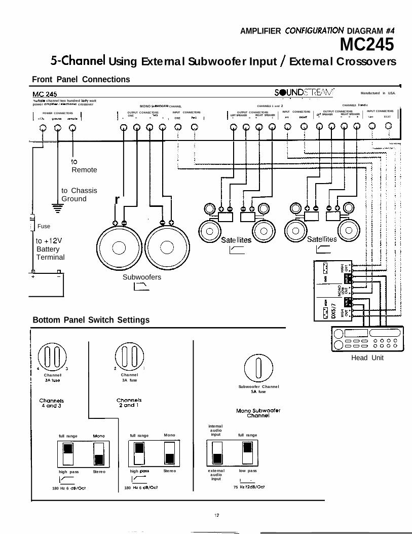
AMPLIFIER CONFlGU?ATION DIAGRAM #4
MC245S-Channel Using External Subwoofer Input / External Crossovers
Front Panel Connections
MC 245muthpk channel two hundred torty wattpower amphtier / ekctron~c crossover
MONO SUIWOOFLR CHANNEL
SWNDSTRE%‘vl* Manufactured in U.S.A.
\ A 3 4 5, :
CHANNELS 1 and 2 CHANNELS 3 rind 4I
I POWER CONNECTORS I I OUTPUT CONNECTORS INPUT CONNECTORSONE TWO
+ - - + I ONE w0 I I OUTPUT CONNECTORS INPUT CONNECTORS OUTPUT CONNECTORS INPUT CONNECTORS
LEFT SPEAKER RIGHT SPEAKER Lfn SPEAKER RIGHT SPEAKER+ - - + I LEFl RIGHT I + - - + I 1ECT RIGHT
t0
Remote
to ChassisGround
Y rO&b
800
Sate
AA0
%00
ites
Fuse
IIto +12vBatteryTerminal
I’
Subwoofers
I
Bottom Panel Switch Settings
@D2 1
[U 000 0000
Head Unit
Subwoofer Channel5A fuse
I Channel3A fuse
Channel
internalaudioinput full rangeMonofull rangefull range
high pars Stereo externalaudioinput
low pass
I -
high pass Stereo
75 Hz 12dB/Oct180 Hz 6 dB/Oct180 Hz 6 dB/Oct

AMPLIFIER CONFIGURATION DIAGRAM #5
MC 140x&Channel FuII-Range System
Front Panel ConnectionsI II
MC 140x SOUNDSTREAM’ Monufoctured in U.S.A.
multiple channel two hundred forty watt c 4 -9 #l iI i:
power amplifier / electronic crossoverCHANNELS 1 and 2 CHANNELS 3 and 4
I
POWER CONNECTORSLEFT SPEAKER RIGHT SPEAKER
+ 12v ground remote I IOUTPUT CONNECTORS
+ - + IINPUT CONNECTORS OUTPUT CONNECTORS INPUT CONNECTORS I
1EV SPEAKER RIGHT SPEAKERLEFI RIGHT I + + I LEFT mGt41 I
r’I A..... / .‘.‘01. \< . ,.... T. .,T . ...,. %. ‘U ..I. ,
,,,., \ A.. ..,.. I_. ..\_ I _..__,,. m Q .Yd(c.w “. ‘*rryrry Y<
to .~ b.\_, \ ,. . I _,,. . . .Remote
. . + ” .
t0
I ChassisGround
Fuse --
to +12v
I
BatteryTerminal+D
Bottom Panel Switch Settings
@4 3 @2 1Channel Channel3A fuse 3A fuse
180 Hz6 dB/Oct
mono
internalhigh audio lowpass I Iinput pass mono
, .
stereo fullrange
Channels4 and 3
externalaudioinput
full stereorange
Channels2 and 1
13
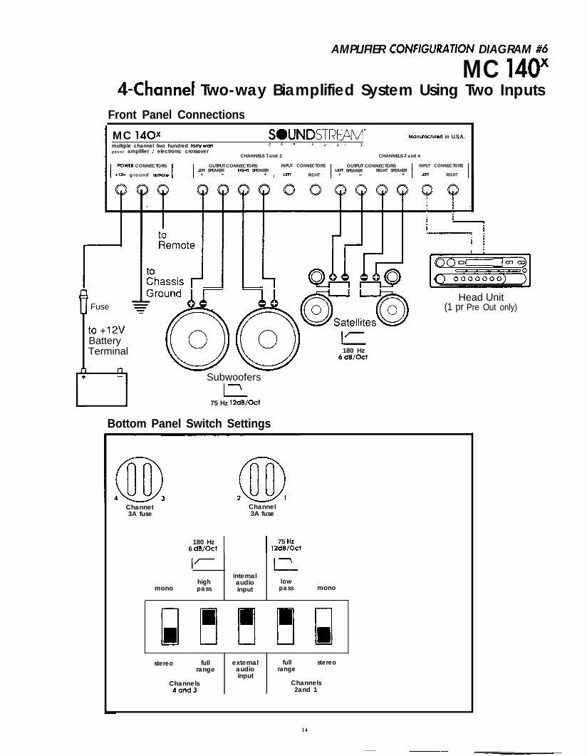
AMPLIFIER COlVFlGU7.ATION DIAGRAM #6
MC 140x&Channel Two-way Biamplified System Using Two Inputs
Front Panel Connections
I MC 140x SOUNDSTREAM’ Monufocfured in U.S.A.
Imultiple channel fwo hundred forfy watf C A P 4 u D 1 3
power amplifier / electronic crossoverCHANNELS 1 and 2 CHANNELS 3 and 4
I’POWER CONNECTORS
I IOUTPUT CONNECTORS
LfFl SPEAKERI
INPUT CONNECTORSRtWT SPEAKER
IOUTPUT CONNECTORS INPUT CONNECTORS
LEFT SPEAKER RIGHT SPEAKER+12v g r o u n d remote + - + LEFl RIGHT + - + I LEFl RIGHT I
Fuse zI
to +12vBatteryTerminal
Head Unit(1 pr Pre Out only)
Subwoofers
L-l\ 75 Hz 12dB/Oct
Bottom Panel Switch Settings
180 Hz6 dB/Oct
Channet Channel3A fuse 3A fuse
180 HzI I
75 Hz6 dB/Oct 12dB/Oct
I’
monohighpass
internalaudioinput
l-2lowpass mono
stereo fullrange
Channels4and3
externalaudioinput
full stereorange
Channels2and 1
14

ti PLlFlER. CO/VFiGURA T/6/V DIAGRAM #7
MC 140x&Channel Two-way Biamplified System Using Four Inputs
Front Panel Connectionsc v
MC 140x SOUNDSTREAM’ Manufactured in U.S.A.
multiple channel fwo hundred forty watt 1. 4 7 4 u I $2power amplifier / electronic crossover
CHANNELS 1 and 2 CHANNELS 3 and 4
IPOWER CONNECTORS
I IOUTPUT CONNECTORS
IINPUT CONNECTORS I OUTPUT CONNECTORS INPUT CONNECTORS
LEFT SPEAKER RIGHT SPEAKER LEFT SPEAKER RIGHT SPEAKER+ 12v ground remote + + LEFT RIGHT + + I LEFT RIGHT I
cl 0 cl Qc=lSS 0 0
Head Unit
\ +Subwoofers
I75 Hrzz/*c+
Bottom Panel Switch Settings
@D4 3 @D2 1Channel Channel3A fuse 3A fuse
180 Hz6 dB/Oct
monohighpass
internaiaudioinput
I
lowpass mono
stereo fullrange
Channels4 and 3
externalaudioinput
full stereorange
Channels2 and 1
15

AMPLIFIER CONFlGLJRATION DIAGRAM #8
. MC140”Z-Channel MI-Range System
Front Panel Connections
I MC 140x SWJNDSTREAM’ Manufactured in U.S.A.
multiple channel two hundred forty watt 2 4 a 4 &I J ! 3
power amplifier / electronic crossoverCHANNELS 1 and 2 CHANNELS 3 and 4
IPOWER CONNECTORS
I IOUTPUT CONNECTORS
IINPUT CONNECTORS OUTPUT CONNECTORS INPUT CONNECTORS
LEFT SPEAKER LEFT SPEAKER RIGHT SPEAKER+12V ground remote + - mY SPEAK:R LEFT RtGttl I + - + I
nt:du UI litI I,,Al I I,
(1 pr Pre Out only)
I to +12vBatterv
I I ermlnal
Bottom Panel Switch Settings
04 3 @D2 1Channel Channel3A fuse 3A fuse
180 Hz 75 Hz6 dB/Oct 12dB/Oct
I/ iinternal
high audio lowmono pass input Pa= mono
stereo fuilrange
Channels4 and 3
externalaudioinput
full stereorange
Channels2and 1
16

AMPLIFIER CONFIGURATION DIAGRAM #9
MC 140xMhannel Two-way Biamplified System
Front Panel Connections
MC 140x SOUNDSTREAM’ Manufactured in U.S.A.
I multiple channel two hundred forty watt ‘4 * .l iipower amplifier / electronic crossover
CHANNELS 1 and 2 CHANNELS 3 and 4
I
POWER CONNECTORS OUTPUT CONNECTORS INPUT CONNECTORS OUTPUT CONNECTORS INPUT CONNECTOIKLEFT SPEAKER RIGHT SPEAKER LEn SPEAKER RIGHT SPEAKER
+12v ground remote I I + + I LEFT RIGHT I + + I LEFT RIGHT I
Remote
Subwoofer
L-L75 Hz
12dB/Oct
180 Hz4 dB/Oct
Bottom Panel Switch Settings
@D2 1Channel3A fuse
mono
180 Hz6 dB/Oct
IL-
highpass
75 Hz12dB/Oct
Iinternalaudio lowinput pass mono
stereo fullrange
Channels4and3
externalaudioinput
full stereorange
Channels2 and 1
17