mbk doodo-yamaha-xn-125150-2000-en.pdf
TRANSCRIPT

XN125 2000
XN1505MF1-AE2
SERVICE MANUAL

EASM0000
XN125 / XN150SERVICE MANUAL
© 2000 by MBK Industrie2nd edition, April 2001
All rights reserved.Any reproduction or unauthorized
use without the writtenpermission of MBK Industrie
is expressly prohibited.

EAS00005
IMPORTANT MANUAL INFORMATIONParticularly important information is distinguished in this manual by the following.
The Safety Alert Symbol means ATTENTION! BECOME ALERT! YOUR SAFETYIS INVOLVED!
Failure to follow WARNING instructions could result in severe injury or death tothe scooter operator, a bystander or a person checking or repairing the scooter.
A CAUTION indicates special precautions that must be taken to avoid damageto the scooter.
A NOTE provides key information to make procedures easier or clearer.NOTE:
WARNING
CAUTION:
EASM0001
NOTICEThis manual was produced by the MBK Industrie primarily for use by Yamaha and MBK dealers andtheir qualified mechanics. It is not possible to include all the knowledge of a mechanic in one manual.Therefore, anyone who uses this book to perform maintenance and repairs on Yamaha and MBKvehicles should have a basic understanding of mechanics and the techniques to repair these typesof vehicles. Repair and maintenance work attempted by anyone without this knowledge is likely torender the vehicle unsafe and unfit for use.
MBK Industrie is continually striving to improve all of its models. Modifications and significant chan-ges in specifications or procedures will be forwarded to all authorized Yamaha and MBK dealers andwill appear in future editions of this manual where applicable.
NOTE:Designs and specifications are subject to change without notice.
TECHNICAL DOCUMENTATIONMBK INDUSTRIE
EAS00007
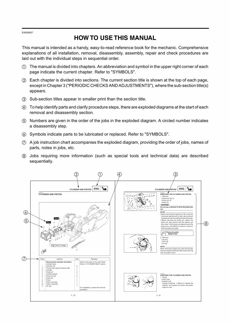
HOW TO USE THIS MANUALThis manual is intended as a handy, easy-to-read reference book for the mechanic. Comprehensiveexplanations of all installation, removal, disassembly, assembly, repair and check procedures arelaid out with the individual steps in sequential order.
The manual is divided into chapters. An abbreviation and symbol in the upper right corner of eachpage indicate the current chapter. Refer to "SYMBOLS".
Each chapter is divided into sections. The current section title is shown at the top of each page,except in Chapter 3 ("PERIODIC CHECKS AND ADJUSTMENTS"), where the sub-section title(s)appears.
Sub-section titles appear in smaller print than the section title.
To help identify parts and clarify procedure steps, there are exploded diagrams at the start of eachremoval and disassembly section.
Numbers are given in the order of the jobs in the exploded diagram. A circled number indicatesa disassembly step.
Symbols indicate parts to be lubricated or replaced. Refer to "SYMBOLS".
A job instruction chart accompanies the exploded diagram, providing the order of jobs, names ofparts, notes in jobs, etc.
Jobs requiring more information (such as special tools and technical data) are describedsequentially.
ENG ENGEASM0025
CYLINDER AND PISTON
Removing the cylinder and piston Remove the parts in the order listed.Cylinder head Refer to “CYLINDER HEAD” section.
1 Cylinder bolt 22 Timing chain guide (exhaust side) 13 Cylinder 14 Dowel pin 25 Cylinder gasket 16 Piston pin clip 27 Piston pin 18 Piston 19 Piston ring (top) 110 Piston ring (2nd) 111 Oil ring 1
For installation, reverse the removalprocedure.
EAS00253
REMOVING THE CYLINDER AND PISTON1. Remove:
• piston pin clip • piston pin • piston
CAUTION:Do not use a hammer to drive the piston pinout.
NOTE:• Before removing the piston pin clip, cover thecrankcase opening with a clean rag to preventthe piston pin clip from falling into the crankcase.
• Before removing the piston pin, deburr thepiston pin clip’s groove and the piston’s pinbore area. If both areas are deburred and thepiston pin is still difficult to remove, remove itwith the piston pin puller.
Piston pin puller90890-01304
2. Remove:• top ring• 2nd ring• oil ring
NOTE:When removing a piston ring, open the end gapwith your fingers and lift the other side of the ringover the piston crown.
EAS00255
CHECKING THE CYLINDER AND PISTON1. Check:
• piston wall• cylinder wallVertical scratches → Rebore or replace thecylinder, and replace the piston and pistonrings as a set.
4 - 23 4 - 24
CYLINDER AND PISTON CYLINDER AND PISTON
Order Job/Part Q’ty Remarks
FWD
1
2
3
45
6
78
910 11
T.R12 Nm (1.2 m•kg)

COOL
GENINFO
ENG
SPEC
22 23
21
24 25
EAS00008
SYMBOLSThe following symbols are not relevant to everyvehicle.Symbols to indicate the subject of eachchapter. General information Specifications Periodic checks and adjustments Engine Cooling system Carburetor Chassis Electrical system Troubleshooting
Symbols to indicate the following. Serviceable with engine mounted Filling fluid Lubricant Special tool Tightening torque Wear limit, clearance Engine speed Electrical data
Symbols to 23 in the exploded diagrams indicatethe types of lubricants and lubrication points. Engine oil Gear oil Molybdenum disulfide oil21 Wheel bearing grease22 Lithium soap base grease23 Molybdenum disulfide grease
Symbols 24 to 25 in the exploded diagramsindicate the following.24 Apply locking agent (LOCTITE®)25 Use a new one
T.R
TRBLSHTG
ELECCHAS
CARB
CHKADJ

GENERAL INFORMATION
SPECIFICATIONS
PERIODIC CHECKS ANDADJUSTMENTS
ENGINE OVERHAUL
COOLING SYSTEM
CARBURETOR
CHASSIS
ELECTRICAL SYSTEM
TROUBLESHOOTING
1
2
3
4
6
7
8
9TRBLSHTG
GENINFO
SPEC
CHKADJ
ENG
CARB
ELEC
CHAS
5COOL
EAS00010
TABLE OF CONTENTS

1GENINFO

CHAPTER 1.GENERAL INFORMATION
SCOOTER IDENTIFICATION ........................................................................1-1VEHICLE IDENTIFICATION NUMBER ....................................................1-1MODEL LABEL ........................................................................................1-1
FEATURES ................................................................................................... 1-2OIL INDICATOR LIGHT ...........................................................................1-2ODOMETER/TRIPMETER READING MODE .........................................1-2BATTERY VOLTAGE/FUEL GAUGE ......................................................1-2THE CLOCK .............................................................................................1-3AUTO-CHOKE SYSTEM .........................................................................1-3
IMPORTANT INFORMATION ...................................................................... 1-4PREPARATION FOR REMOVAL AND DISASSEMBLY ........................ 1-4REPLACEMENT PARTS ........................................................................ 1-4GASKETS, OIL SEALS AND O-RINGS .................................................. 1-4LOCK WASHERS/PLATES AND COTTER PINS ................................... 1-5BEARINGS AND OIL SEALS .................................................................. 1-5CIRCLIPS ................................................................................................ 1-5
CHECKING THE CONNECTIONS ............................................................... 1-6
SPECIAL TOOLS ..........................................................................................1-7
GENINFO

GENINFOSCOOTER IDENTIFICATION
EAS00015
GENERAL INFORMATIONSCOOTER IDENTIFICATIONEASM0002
VEHICLE IDENTIFICATION NUMBERThe vehicle identification number is stampedinto the frame.
EASM0003
MODEL LABELThe model label is affixed under the seat.This information will be needed to order spareparts.
1-1
ZAUM0071
ZAUM0072

GENINFO
1-2
FEATURESEASM0004
FEATURESOIL INDICATOR LIGHT• FUNCTIONPulses (travel distance signals) from the speedometer are counted and cause the oil indicator lightto come on at 500 km for the first time and thereafter every 3,000 km. In this way, the light indicatesthe time for oil change.
• RESETTING PROCEDURETo reset the oil change indicator light
1) Press the “TRIP” button while turning the key to “ON”.2) Release the button and the oil change indicator light will go off.
NOTE:To reset the oil change indicator light before the periodic oil change interval has been reached, followthe above procedure.
ODOMETER/TRIPMETER READING MODEThe odometer and tripmeter can be set to count in either miles or kilometers according to the followingprocedure.
1) Turn the key to “ON”.2) Press the “TRIP” button until the current mode appears in the dispaly:
“CONT” (continental) for kilometer mode and “EnGL” (English) for the mile mode.3) Press the “TRIP” button to switch mode.4) Press the “TRIP” button for two seconds to confirm the setting.
NOTE:• The odometer/tripmeter reading mode can be changed any number of times while the odometerreading is below 10, but it cannot changed anymore after the reading has reached 10.
• Switching between the mile and the kilometer mode does not change or convert the current odometer/tripmeter reading.
BATTERY VOLTAGE/FUEL GAUGEWhen the key is turned to “OFF”, the voltage/fuel gauge indicates the battery voltage.
NOTE:If the battery voltage drops to 10V, refer to “CHECKING THE BATTERY” section in chapter 3.
When the key is turned to “ON”, the voltage/fuel gauge indicates the amount of fuel in the fuel tankafter indicating the battery voltage for two seconds.

GENINFO
THE CLOCK• Setting the clockTo set the clock:
1) Make sure that the key is turned to “OFF”.2) Press the “TRIP” button for two seconds and the hour display will flash.3) Press the “TRIP” button to set the hours.4) Press the “TRIP” button for two seconds, and the first minute digit will flash.5) Press the “TRIP” button to set the first minute digit.6) Press the “TRIP” button for two more seconds, and the second minute digit will flash.7) Press the “TRIP” button to set the second minute digit.8) Press the “TRIP” button for two seconds to set the clock.
AUTO-CHOKE SYSTEMThis system is the parallel connection of the ignitor unit circuit and the thermo switch as shown,detecting the engine temperature, and facilitates the restarting with the warm engine.• Circuit diagram
• Auto-choke operation
FEATURES
Main switch
Fuse
Battery
Thermoswitch
Auto-choke
Ignitor unit
C.P.UIgnition
Engine condition Start with the Crank with the Crank with the Restart with thecold engine cold engine warm engine warm engine
Thermo switch OFF OFF ON ON
Ignitor unit circuit OFF ON ON OFFAuto-choke Activates Activates Not activate Not activate
1-3

GENINFO
EAS00020
IMPORTANT INFORMATIONPREPARATION FOR REMOVAL ANDDISASSEMBLY1.Before removal and disassembly, remove all
dirt, mud, dust and foreign material.2.Use only the proper tools and cleaning equip-
ment.Refer to the “SPECIAL TOOLS”.
3.When disassembling, always keep mated partstogether. This includes gears, cylinders, pis-tons and other parts that have been “mated”through normal wear. Mated parts must al-ways be reused or replaced as an assembly.
4.During disassembly, clean all of the parts andplace them in trays in the order of disassem-bly. This will speed up assembly and allow forthe correct installation of all parts.
5.Keep all parts away from any source of fire.
EAS00021
REPLACEMENT PARTS1.Use only genuine Yamaha and MBK parts for
all replacements. Use oil and grease recom-mended by Yamaha or MBK for all lubricationjobs. Other brands may be similar in functionand appearance, but inferior in quality.
EAS00022
GASKETS, OIL SEALS AND O-RINGS1.When overhauling the engine, replace all gas-
kets, seals and O-rings. All gasket surfaces,oil seal lips and O-rings must be cleaned.
2.During reassembly, properly oil all matingparts and bearings and lubricate the oil seallips with grease.
IMPORTANT INFORMATION
1-4
GENINFO
IMPORTANT INFORMATION
EAS00023
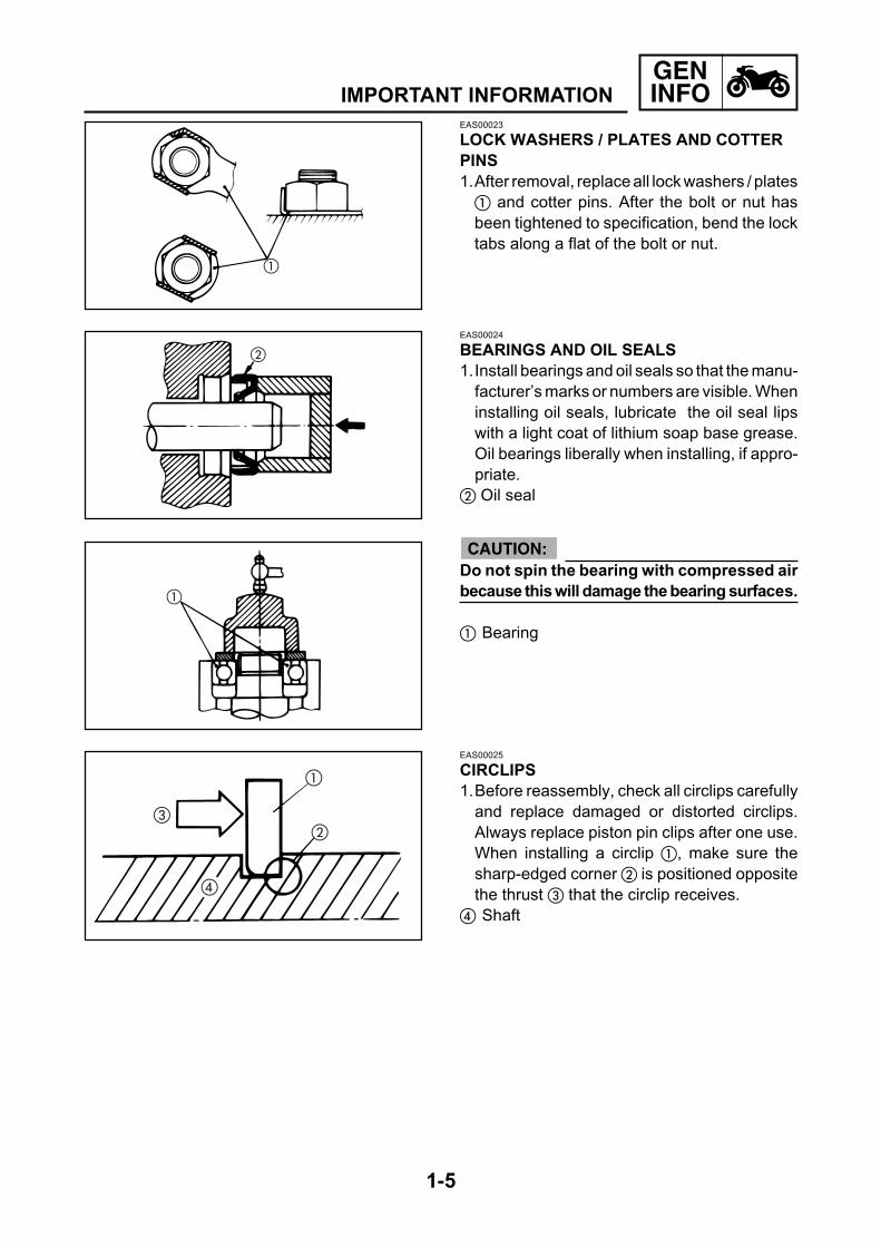
LOCK WASHERS / PLATES AND COTTERPINS1.After removal, replace all lock washers / plates
and cotter pins. After the bolt or nut hasbeen tightened to specification, bend the locktabs along a flat of the bolt or nut.
EAS00024
BEARINGS AND OIL SEALS1.Install bearings and oil seals so that the manu-
facturer’s marks or numbers are visible. Wheninstalling oil seals, lubricate the oil seal lipswith a light coat of lithium soap base grease.Oil bearings liberally when installing, if appro-priate.
Oil seal
EAS00025
CIRCLIPS1.Before reassembly, check all circlips carefully
and replace damaged or distorted circlips.Always replace piston pin clips after one use.When installing a circlip , make sure thesharp-edged corner is positioned oppositethe thrust that the circlip receives.
Shaft
Do not spin the bearing with compressed airbecause this will damage the bearing surfaces.
Bearing
CAUTION:
1-5

GENINFOCHECKING THE CONNECTIONS
+-
+-
EAS00026
CHECKING THE CONNECTIONSCheck the leads, couplers, and connectors forstains, rust, moisture, etc.1.Disconnect:• lead• coupler• connector
2.Check:• lead• coupler• connectorMoisture → Dry with an air blower.Rust/stains → Connect and disconnect sev-eral times.
3.Check:• all connectionsLoose connection → Connect properly.
NOTE:If the pin on the terminal is flattened, bend itup.
4.Connect:• lead• coupler• connector
NOTE:Make sure all connections are tight.
5.Check:• continuity(with the pocket tester)
Pocket tester90890-03112
NOTE:• If there is no continuity, clean the terminals.• When checking the wire harness, perform steps1 to 3.
• As a quick remedy, use a contact revitalizeravailable at most part stores.
1-6

GENINFOSPECIAL TOOLS
EAS00027
SPECIAL TOOLSThe following special tools are necessary for complete and accurate tune-up and assembly. Useonly the appropriate special tools as this will help prevent damage caused by the use of inappropriatetools or improvised techniques. Special tools, part numbers or both may differ depending on thecountry.When placing an order, refer to the list provided below to avoid any mistakes.
Slide hammer bolt (M6)Weight
These tools are used to remove orinstalling the rocker arms shafts.
Rotor holding tool
This tool is used to remove the flywheelmagneto.
Ring nut wrench Steering nut wrench
These tools are used to loosen and tightenthe steering ring nuts.
Damper rod holderT-handle
These tools are used for disassemblingor assembling the front fork.
Piston pin puller
This tool is used to remove the piston pins.
Fuel level gauge
This tool is used to measure the fuel levelin the float chamber.
Clutch spring holderClutch spring holder arm
These tools are used for removing the nutwith holding the compression spring.
90890-0108390890-01084
90890-01235
90890-0126890890-01403
90890-0129490890-01326
90890-01304
90890-01312
90890-0133790890-01464
Tool No. Tool name/usage Illustration
1-7

GENINFO
Fork seal driver weightFrok seal driver attachment
These tools are used when installing thefork seal.
Sheave holder
This tool is used to hold the secondarysheave when removing or installing thenut.
Valve adjusting tool
This tool is necessary for adjusting valveclearance.
Pocket Tester
This instrument is invaluable for checkingthe electrical system.
Engine tachometer
This tool is needed for detecting theengine rpm.
Timing light
This tool is needed for detecting ignitiontiming.
Valve spring compressorAttachment
These tools are used when removing orinstalling the valve and the valve spring.
Valve guide remover
This tool is used to remove the valveguide.
90890-0136790890-01368
90890-01701
90890-03111
90890-03112
90890-03113
90890-03141
90890-0401990890-04108
90890-04116
SPECIAL TOOLS
Tool No. Tool name/usage Illustration
1-8

GENINFO
Valve guide installer
This tool is needed to install the valveguide spring.
Valve guide reamer
This tool is used to rebore the valve guide.
Ignition checker
This instrument is necessary for checkingthe ignition system components.
Yamaha bond No. 1215
This sealant (bond) is used for crankcasemating surface, etc.
Compression gauge
This gauge is used to measure the enginecompression.
90890-04117
90890-04118
90890-06754
90890-85505
90890-03081
Tool No. Tool name/usage Illustration
SPECIAL TOOLS
1-9

2SPEC

CHAPTER 2.SPECIFICATIONS
GENERAL SPECIFICATIONS ......................................................................2-1
MAINTENANCE SPECIFICATIONS .............................................................2-4ENGINE ...................................................................................................2-4CHASSIS .................................................................................................2-8ELECTRICAL .........................................................................................2-10
CONVERSION TABLE ............................................................................... 2-12
GENERAL TIGHTENING TORQUE SPECIFICATIONS ............................ 2-13
TIGHTENING TORQUES ........................................................................... 2-14TIGHTENING TORQUES (ENGINE) ..................................................... 2-14TIGHTENING TORQUES (CHASSIS) ...................................................2-16
LUBRICATION POINTS AND LUBRICANT TYPES .................................. 2-17ENGINE .................................................................................................2-17CHASSIS ...............................................................................................2-18
COOLING SYSTEM DIAGRAMS ............................................................... 2-19
LUBRICATION DIAGRAMS ....................................................................... 2-21
CABLE ROUTING .......................................................................................2-23
SPEC

2-1
SPECGENERAL SPECIFICATIONS
SPECIFICATIONSGENERAL SPECIFICATIONS
DimensionsOverall lengthOverall widthOverall heightSeat heightWheelbaseMinimum ground clearanceMinimum turning radius
WeightWet (with oil and a full fuel tank)Dry (without oil and fuel)
EngineEngine typeCylinder arrangementDisplacementBore x strokeCompression ratioStandard compression pressure (at sea level)Starting system typeLubrication system
Oil capacityEngine oil
Periodic oil changeTotal amountFinal gear case oilTotal amount
Coolant systemRadiator capacity (including all routes)Coolant reservoir capacity<from low to full level>
Air filter type
FuelRecommended fuelFuel tank capacity
1.868 mm740 mm
1.096 mm777 mm
1.315 mm105 mm
1.800 mm
123 kg116 kg
Liquid cooled 4-stroke, SOHCForward inclined single cylinder124 cm3 [152 cm3]53.7 x 54.8 mm [59.5 x 54.8 mm]11: 011.400kPa/500r/min (14kgf/cm2/500r/min)Electric starterWet sump
API STANDARD: SE or higher grade
1.2 L1.4 L
0.15 L
1.1 L0.35 L<0.25 L>
Dry element
Regular unleaded gasoline10 L
Item XN125 [XN150]
Temp.-20 -10 0 10 20 30 40
10W/30
10W/40
20W/40
20W/50

2-2
SPECGENERAL SPECIFICATIONS
CarburatorType/quantityManufacturer
Spark plugTypeManufacturerSpark plug gap
Clutch type
TransmissionPrimary reduction systemPrimary reduction ratioSecondary reduction systemSecondary reduction ratioTransmission typeOperation
ChassisFrame typeCaster angleTrail
TyreTyre typeSize (front)Size (rear)Manufacturer (front)Manufacturer (rear)Type (front)Type (rear)
Tyre pressure (cold)Maximum load*-except motorcycleLoading condition AFrontRearLoading condition BFrontRear
Front wheelWheel typeRim size
Rear wheelWheel typeRim size
TK 5DS/1 [TK 5KD/1]TEIKEI
CR8ENGK0.5~0.7 mm
Dry, centrifugal automatic
Helical gear40/15 (2.666)Spur gear44/12 (3.666) [42/14 (3)]V-belt automaticCentrifugal automatic type
Steel tube backbone26°80 mm
Tubeless120/70-12120/70-12METZELERMETZELER7-TEEN7-TEEN
187 kg
180 kPa (1.80 kgf/cm2)200 kPa (2.00 kgf/cm2)
200 kPa (2.00 kgf/cm2)220 kPa (2.20 kgf/cm2)
Cast wheel12 x MT3.50
Cast wheel12 x MT3.50
Item XN125 [XN150]

2-3
SPEC
BrakeFront brake typeFront brake operationRear brake typeRear brake operation
SuspensionFront suspensionRear suspension
Shock absorberFront fork typeRear shock absorber assembly type
Wheel travelFront wheel travelRear wheel travel
ElectricalIgnition system typeCharging system typeBattery typeBattery voltage/capacity
Headlight typeBulbs (voltage/wattage x quantity)HeadlightPosition lightBrake/tail lightFront flasher lightRear flasher lightMeter lightHigh beam indicator lightTurn indicator lightCoolant temperature warning light
Amperage for fusesMain fuseRadiator fan fuse
Single disc brakeRight hand operationDrum brakeLeft hand operation
Telescopic forkUnit swing
Coil spring/oil damperCoil spring/oil damper
90 mm80 mm
C.D.IFlywheel magnetoCB7L-B2 or YB7L-B212V 8Ah
Bulb
12V 35W/35W x 212V 5W x 112V 21W/5W x 112V 21W x 212V 10W x 212V 1.2W x 212V 1.2W x 112V 1.2W x 212V 1.2W x 1
20 A7.5 A
Item XN125 [XN150]
GENERAL SPECIFICATIONS

2-4
SPEC
MAINTENANCE SPECIFICATIONSENGINE
Cylinder headWarp limit
CylinderBore sizeOut of round limit
CamshaftDrive systemCam dimensions Intake “A”
“B”“C”
Exhaust “A”“B”“C”
Camshaft runout limit
Cam chainCam chain type/No. of links
Rocker arm/rocker armshaftRocker arm inside diameterRocker shaft outside diameter
Valve,valve seat, valve guideValve clearance (cold) IN
EXValve dimensions
“A” head diameter INEX
“B” face width INEX
“C” seat width INEX
Stem outside diameter INEX
Guide inside diameter INEX
Stem-to-guide clearence INEX
Stem runout limitValve seat width IN
EX
A
C
B
A
B C
Face width Seat width
Item Standard Limit
MAINTENANCE SPECIFICATIONS
*[XN150]
••• 0.03 mm
53.700 ~ 53.705 mm [59.500 ~ 59.505mm]* •••••• 0.05 mm
Chain drive (left) •••
30.811 ~ 30.911 mm 30.711 mm25.145 ~ 25.245 mm 25.045 mm5.666 m •••30.811 ~ 30.911 mm 30.711 mm25.152 ~ 25.252 mm 25.052 mm5.659 m •••••• 0.03 mm
82 RH2005/94 •••
12.000 ~ 12.018 mm 12.030mm11.981 ~ 11.991 mm 11.950 mm
0.10 ~ 0.14 mm •••0.16 ~ 0.20 mm •••
26.9 ~ 27.1 mm •••22.9 ~ 23.1 mm •••2.687 ~ 3.252 mm •••2.687 ~ 3.252 mm •••0.9 ~ 1.1 mm •••0.9 ~ 1.1 mm 1.6 mm4.475 ~ 4.490 mm 4.445 mm4.460 ~ 4.475 mm 4.430 mm4.500 ~ 4.512 mm 4.542 mm4.500 ~ 4.512 mm 4.542 mm0.01 ~ 0.037 mm 0.08 mm0.025 ~ 0.052 0.10 mm••• 0.01 mm0.9 ~ 1.1 mm 1.6 mm0.9 ~ 1.1 mm 1.6 mm

2-5
SPEC
Valve springInner springFree length IN/EXSet length (valve closed) IN/EXCompressed pressure IN/EXTilt limit IN/EX
PistonPiston to cylinderclearencePiston size “D”Measuring point “H”Piston pin bore inside diameterPiston pin outside diameter
Piston ringsTop ring: Type End gap (installed) Side clearance (installed)2 nd ring: Type End gap (installed) Side clearence (installed)Oil ring: End gap (installed)
Crankshaft
Crank width “A”Runout limit “C”Big end side clearance “D”
Automatic centrifugal clutchClutch shoe thicknessClutch housing inside diameterWeight outside diameterClutch-in revolutionClutch-stall revolution
V-BeltV-belt width
41.94 mm 39.84 mm37.5 mm •••45.1 ~ 50.9 N •••2.5° / 1.9 mm •••
0.025 ~ 0.035 mm 0.15 mm
53.670 ~ 53.687 mm [59.470 ~ 59.487 mm]* •••4.5 mm •••15.002 ~ 15.013 mm 15.045 mm14.991 ~ 15.000 mm 14.975 mm
Barrel •••0.15 ~ 0.25 mm 0.50 mm0.03 ~ 0.07 mm 0.12 mm
Taper •••0.15 ~ 0.30 mm 0.65 mm0.02 ~ 0.06 mm 0.12 mm
0.2 ~ 0.7 mm •••
47.950 ~ 48.000 mm •••••• 0.03 mm0.15 ~ 0.45 mm •••
2.0 mm 1.0 mm120 mm [135 mm]* 120.5 [135.5 ]*20.0 mm 19.5 mm3,550 ~ 4,050 rpm [3,250 ~ 3,750 rpm]* •••5,900 ~ 6,900 rpm [5,600 ~ 6,400 rpm]* •••
22 mm 19 mm
Item Standard Limit
H
D
MAINTENANCE SPECIFICATIONS*[XN150]

2-6
SPEC
CarburetorTypeI.D markMain jet (M.J)Main air jet (M.A.J)Jet needle (J.N)Pilot air jet (P.A.J.1)Needle jet (N.J)Pilot jet (P.J)Pilot screw (P.S)Valve seat size (V.S)Starter jet 1 (G.S.1)Float height (F.L)Engine idle speed
Oil pumpTypeTip clearenceSide clearanceHousing and rotor clearence
RadiatorTypeWidth/height thicknessRadiator cap opening pressureReservoir tank capacity
Thermostatic valveManufacturerValve opening temperatureValve full open temperature
TK 5DS [TK 5KD]*••• •••#116 [#114]* •••ø1.0 [ø1.4]* •••4E31 (3/5) [4E32 (3/5)]* •••ø1.30 •••2.590 •••#38 [#36] •••2 1/4 ~ 2 3/4 [2 ~ 4]* •••ø2.00 •••#0.45 •••5 ~ 6 mm •••1.600 ~ 1.800 rpm •••
Trochoid •••••• 0.15 mm••• 0.15 mm••• 0.17 mm
Cooling fin with electric fan •••170 / 282 / 29 mm •••90 ~ 110 kPa •••0.35 L •••
ANGLI •••82 ±3°C •••95 ±3°C •••
Item Standard Limit
MAINTENANCE SPECIFICATIONS*[XN150]

2-7
SPEC
Crankshaft oil seal (left)Crankshaft oil seal (right)Crankshaft oil seal (right)Camshaft bearing (left)Camshaft bearing (right)Starter clutch bearingPrimary drive gear bearing (left)Primary drive gear bearing (right)Primary drive gear oil sealMain axle bearing (left)Main axle bearing (right)Drive axle bearing (left)Drive axle bearing (right)Drive axle oil seal
22 x 32 x 719 x 30 x 8 (Reinforced)19 x 30 x 8 (Double lips)20 x 42 x 1215 x 32 x 917 x 35 x 1025 x 52 x 1517 x 40 x 1225 x 42 x 6 (Double lips)15 x 25 x 12 (Needle bearing)12 x 37 x 1217 x 47 x 14 (Sphere)22 x 50 x 14 (Sphere)32 x 52 x 7
Item Size
MAINTENANCE SPECIFICATIONS

2-8
SPEC
Steering systemSteering bearing typeNo./size of steel balls Upper
Lower
Front suspensionFront fork travelSpring rate (K1)Stroke (K1)Oil capacityOil gradeInner tube outer diameterOptional spring
Rear suspensionShock absorber travelFitting lengthSpring rate (K1)
(K2)Stroke (K1)
(K2)
Front wheelTypeRim sizeRim materialRim runout limit Radial
Lateral
Rear wheelTypeRim sizeRim materialRim runout limit Radial
Lateral
Front disc brakeTypeDisc outside diameter x thicknessPad thicknessMaster cylinder inside diameterCaliper cylinder outside diameterBrake fluid type
Rear drum brakeTypeDrum inside diameterShoe thicknessShoe spring free length
MAINTENANCE SPECIFICATIONSCHASSIS
Item Standard Limit
MAINTENANCE SPECIFICATIONS
Ball bearing •••15 pcs 4.75 mm •••15 pcs 4.75 mm •••
90 mm •••11 N/mm •••0 ~ 90 mm •••125 cm3 •••SAE20 •••33 mm •••No •••
80 mm •••229 mm •••18 N/mm •••53.5 N/mm •••0 ~ 60 mm •••60 ~ 80 mm •••
Cast wheel •••MT 3.50 x 12 •••Aluminium •••••• 1 mm••• 0.5 mm
Cast wheel •••MT 3.50 x 12 •••Aluminium •••••• 1 mm••• 0.5 mm
Single •••220 x 4.5 mm •••4 mm 0.8 mm11 mm •••32 mm •••DOT #3 or DOT #4 •••
Leading, trailing •••130 mm 130.5 mm4.0 mm 2.0 mm54 mm •••

2-9
SPEC
Brake leverBrake lever free play (front)Brake lever free play (rear)Throttle cable free play
Item Standard Limit
MAINTENANCE SPECIFICATIONS
10 ~ 20 mm •••10 ~ 20 mm •••1.5 ~ 3.0 mm •••

2-10
SPEC
Ignition timingIgnition timing (B.T.D.C)Advanced timing (B.T.D.C)Advanced type
T.C.IPickup coil resistance/color
Source coil resistance/color
Ignition coilMinimum spark gapPrimary winding resistanceSecondary winding resistance
Spark plug capTypeResistance
Charging systemTypeNormal outputStator coil resistance/color
Rectifier/regulatorModel/manufacturerNo load regulated voltageCapacityWithstand voltage
BatterySpecific gravity
Electric starting systemTypeStarter motor:Operation voltageOutputArmature coil resistanceBrush overall lengthBrush quantitySpring forceCommutator diameterMica undercut (depth)
Starter relayModel/manufacturerAmperage ratingCoil winding resistance
MAINTENANCE SPECIFICATIONSELECTRICAL
MAINTENANCE SPECIFICATIONS
Item Standard Limit
10° at 1.700 rpm •••32° at 5.000 rpm •••Digital •••
248 ~ 372 Ω at 20°C / •••white / red-white / blue720 ~ 1080 Ω at 20°C / •••green/white - brown/black
6 mm •••0.32 ~ 0.48 Ω at 20°C •••5.7 ~ 8.5 kΩ at 20°C •••
Resin type •••10 kΩ •••
Flywheel magneto •••14 V 10.5 A at 5.000 rpm •••0.6 ~ 0.9 Ω at 20°C/white - white - white
14.5 V •••25 A •••200 V •••
1.280 •••
Constant mesh type •••
12 V •••0.3 kW •••0.0306 ~ 0.0374 Ω at 20°C •••10 mm 3.5 mm2 •••5.6 ~ 8.3 N •••22 mm 21 mm1.5 mm •••
9768054/JIDECO •••100 A •••4.2 ~ 4.6 Ω at 20°C •••

2-11
SPEC
HornModel/manufacturerMaximum amperage
Flasher relayFlasher frequency
Fuel gaugeModel/manufacturerSender unit resistance - full
- empty
Circuit breakerMainRadiagtor fan fuse
YF-12 / NIKKO •••3 A •••
80 ~ 160 cycle/min •••
25.33.06/MAXIMA •••4 ~ 10 Ω •••90 ~ 100 Ω •••
20 A x 1 pcs •••7.5 A x 1 pcs •••
MAINTENANCE SPECIFICATIONS
Item Standard Limit

2-12
SPEC
METRIC TO IMPERIALMetric unit Multiplier Imperial unit
Torque m•kg 7.233 ft•lbm•kg 86.794 in•lbcm•kg 0.0723 ft•lbcm•kg 0.8679 in•lb
Weight kg 2.205 lbg 0.03527 oz
Speed km/h 0.6214 mph
km 0.6214 mim 3.281 ft
Distance m 1.094 ydcm 0.3937 inmm 0.03937 in
cc (cm3) 0.03527 oz(IMP liq.)
Volume/ Capacitycc (cm3) 0.06102 cu•inL (liter) 0.8799 qt(IMP liq.)L (liter) 0.2199 gal(IMP liq.)
kg/mm 55.997 lb/inMisc. kg/cm2 14.2234 psi(lb/in2)
Centigrade (°C) 9/5+32 Fahrenheit (°F)
CONVERSION TABLEAS00028
CONVERSION TABLEAll specification data in this manual are listed in SI and METRIC UNITS.Use this table to convert METRIC unit data to IMPERIAL unit data.Ex.
METRIC MULTIPLIER IMPERERIAL** mm x 0.03937 = ** in2 mm x 0.03937 = 0.08 in
CONVERSION TABLE

2-13
SPEC
EAS00029
GENERAL TIGHTENING TORQUE SPECIFICATIONSThis chart specifies tightening torques for standard fasteners with a standard ISO thread pitch.Tightening torque specifications for special components or assemblies are provided for each chapterof this manual. To avoid warpage, tighten multi-fastener assemblies in a crisscross pattern andprogressive stages until the specified tightening torque is reached. Unless otherwise specified,tightening torque specifications require clean, dry threads. Components should be at roomtemperature.
A: Width across flatsB: Thread diameter
BA
A B General tightening(nut) (bolt) torques
Nm m•kg10 mm 6 mm 6 0.6
12 mm 8 mm 15 1.5
14 mm 10 mm 30 3.0
17 mm 12 mm 55 5.5
19 mm 14 mm 85 8.5
22 mm 16 mm 130 13.0
GENERAL TIGHTENING TORQUE SPECIFICATIONS

2-14
SPEC
Oil check bolt Bolt M6 1 9 0.9Spark plug - M10 1 13 1.3Cylinder, water drain bolt Bolt M6 1 8 0.8Cylinder head and cylinder Nut M8 4 22 2.2Cylinder head and cylinder Bolt M6 2 12 1.2Cylinder and crankcase Bolt M6 1 12 1.2Camshaft bearing stopper Bolt M6 1 12 1.2Camchain guide Bolt M6 1 6.5 0.65Valve adjuster nut Nut M5 2 6.5 0.65Camshaft pinion bolt Bolt M8 1 30 0.3Camshaft tensionner Bolt M6 2 10 1.0Rocker shaft securing plate Bolt M6 1 10 1.0Thermostatic valve cover Bolt M6 1 9 0.9Water pump housing cover Bolt M6 4 10 1.0Water pump housing Bolt M6 2 7 0.7Water pump housing Bolt M6 1 7 0.7Thermostatic valve cover Bolt M6 2 9 0.9Oil pump Bolt M6 3 65 6.5Engine drain plug M35 1 32 3.2Inlet manifold on cylinder head Bolt M6 2 10 1.0Air filter cover Bolt M6 8 6.5 0.65Exhaust pipe stud bolt on cylinder Nut M6 2 11 1.1Muffler on bracket Bolt M8 2 27 2.7Muffler bracket on crankcase Bolt M8 2 27 2.7Muffler protector Bolt M6 2 4.5 0.45Crankcase (left) Bolt M6 8 9 0.9Cover, crankcase 1 Bolt M6 11 10 1.0Cover, crankcase 2 Bolt M6 6 10 1.0Cover, oil pump Bolt M6 3 6.5 0.65Duct, air Bolt M6 3 7 0.7Cover, magneto Bolt M6 3 7 0.7Cylinder head stud bolt Stud M8 4 13 1.3Transmission oil drain plug Plug M8 1 22 2.2Engine oil drain plug Plug M8 1 22 2.2Cover, crankcase 3 Bolt M6 2 6.5 0.65Starter idle gear plate Bolt M6 2 7 0.7Primary fixed sheave Nut M14 1 60 6.0Clutch carrier assembly Nut M36 1 90 9.0Clutch housing Nut M12 1 55 5.5
TIGHTENING TORQUESENGINE
TIGHTENING TORQUES
Item FastenerThread
size Q'tyTightening
torque
Nm m•kgRemarks

2-15
SPEC
Rear brake shoes pin pivot Nut M10 1 120 12.0Thermo unit - Pt 1/8 1 75 7.5Coolant drain bolt on cylinder Bolt M6 1 8 0.8Starter motor Bolt M6 2 65 6.5Rotor Nut M12 1 70 7.0
M16 1 225 22.5M16 1 225 22.5
Stator Bolt M6 3 70 7.0
Item FastenerThread
size Q'tyTightening
torque
Nm m•kgRemarks
TIGHTENING TORQUES

2-16
SPECTIGHTENING TORQUES
Frame with engine bracket Bolt M10 1 42 4.2Engine bracket 2 with 3 Bolt M10 2 55 5.5E/G bracket with E/G (with main stand) Bolt M10 2 32 3.2Reinforcement tail Bolt M6 4 6.5 0.65Rear cushion with frame Nut M10 1 32 3.2Rear cushion with engine Nut M8 1 18 1.8 See chapter 7Steering shaft Nut M25 3 “STEERINGHandle with steering shaft Nut M10 1 60 6.0 HEAD”
Master cylinder with handle Bolt M6 2 8.5 0.85Seat lock Bolt M6 2 4 0.4Box with frame Bolt M6 2 8 0.8Box with reinforcement tail Bolt M6 2 8 0.8Carrier with frame Bolt M8 1 19 1.9Carrier with reinforcement tail Bolt M8 2 19 1.9Footrest board with frame Bolt M6 4 4 0.4Mud guard with frame Bolt M6 2 7 0.7Fender on front fork Bolt M6 3 4 0.4Cover handle with handle Bolt M5 2 4.5 0.45Mainstand Nut M10 2 42 4.2Rear footrest Nut M8 2 14 1.4Front wheel axle Nut M12 1 70 7.0Rear wheel axle Nut M14 1 104 10.4Rear brake cam lever Nut M6 1 14 1.4Rear brake pin pivot Nut M10 1 12 1.2Front caliper on front fork Bolt M8 2 23 2.3Front brake disc on wheel Bolt M8 4 23 2.3Union bolt with caliper Bolt M10 1 23 2.3Union bolt with master cylinder Bolt M10 1 23 2.3
TIGHTENING TORQUESCHASSIS
Item FastenerThread
size Q'tyTightening
torque
Nm m•kgRemarks

2-17
SPEC
Lubrication Point Symbol
Oil seal lips
O-ring (Except V-belt drive unit)
Cylinder head tightening nut mounting surface
Crankshaft pin outside
Connecting rod big end thrust surface
Rotary filter inner surface
Drive gear inner surface
Cam chain outside sprocket inner surface
Piston pin
Piston outside and ring groove
Camshaft cam profile
Valve stem (IN, EX)
Valve stem end (IN, EX)
Rocker shaft
Valve rocker arm inner surface
Shaft
Shaft (Oil pump assembly)
Gasket (Oil pump assembly)
Holder
Idle gear 1 thrust surfaces
Shaft 1
Idle gear 2 thrust surfaces
Idle gear 2 inner surface
Main axle thrust surfaces
Crankcase mating surfaces Yamaha bond No. 1215
Crankcase breather plug
Stator grommet Yamaha bond No. 1215
Suction pipe
LUBRICATION POINTS AND LUBRICANT TYPESEAS00031
LUBRICATION POINTS AND LUBRICANT TYPESENGINE

2-18
SPECLUBRICATION POINTS AND LUBRICANT TYPESEAS00032
CHASSIS
Lubrication Point Symbol
Front wheel oil seal lips (left/right)
Steering head pipe bearing (upper/lower)
Tube guide (throttle grip) inner surface
Brake cable (brake lever)
Brake lever and lever holder bolt sliding surface
Sidestand sliding surface
Centerstand sliding surface and mounting bolt
Centerstand stopper pivot shaft
Brake cam pivot shaft and cam surface

2-19
SPECCOOLING SYSTEM DIAGRAMSEAS00033
COOLING SYSTEM DIAGRAMS Radiator cap Radiator Radiator fan Thermo switch Coolant tank Water pump Cylinder Inlet manifold
A
A Pass the hose under inlet manifold.

2-20
SPECCOOLING SYSTEM DIAGRAMSEAS00033(bis)
COOLING SYSTEM DIAGRAMS Radiator Radiator fan Radiator cap Coolant tank Water pump Thermostat
A
A Pass the hose between radiator and radiatorfiller hose.

2-21
SPECLUBRICATION DIAGRAMSEAS00034
LUBRICATION DIAGRAMS 1Lubrication of the cylinder head
Cylinder head Cylinder Crankcase
2Lubrication of the crankshaft Crankshaft
2
1

2-22
SPECEAS00034(bis)
LUBRICATION DIAGRAMS 1Oil flow
Cylinder head Cylinder Oil pump
2Lubrication tableA Oil pressure flowB Oil return flow
LUBRICATION DIAGRAMS
Rocker arm
Camshaft
Cylinder head
Oil pump
Oil strainer
Crankcase
Crankshaft
Connecting rod
AB
1
2

2-23
SPECEAS00035
CABLE ROUTING Thermo switch wire Seat lock cable Speedometer wire Main switch wire Seat lock cable adjuster Radiator Fan Headlight and front flasher connector Front fork assembly
Wire harness Horn Horn wire Rear brake cable Throttle cable Band switch
A Make the wire harness getting out here.BPlace the speedometer wire as shown.CPass the thermo switch lead between the
hoses.
CABLE ROUTING
FA
FA
A
AA
A-A
B
5~10 mm
C

2-24
SPECCABLE ROUTING Starter motor CDI unit rectifier/Regulator CDI magneto wire Ignition coil assembly Footrest board Starter relay Battery ground Wire harness
Seat lock assembly Fuel tank Wire lead Mud guard Fuel cock
A Place the wire as shown.BPlace the sidestand wire as shown (option).C Apply grease on stater motor connector/
terminal.
1
6
A
A-A B-B
C-CA
B
D
D-D
D
C
C
B
B
A
~110 mm
5~10 mm 5~10 mm
C

2-25
SPEC
Rear left flasher Rear brake cable adjuster Rear brake cable Fuel overflowed pipe Fan Radiator Main switch Sidestand wire (option) Fueal gauge wire Rear right flasher Taillight Seat lock cable Throttle cable
Battery Starter relay Frame Fuses box Relay Sender Fuel pipe21 Engine air breather22 Fuel cock23 Seat lock assemblyA Connection for anti-thelf (option)BPlace the Starter motor ground as shown.CPass the carburetor breather hose between
air duct and air filter case.
A
B
C
10
19
23
22
20
21
2013
18
8
7
65
17 16
13
12
14 15
11
9
3
1
2
3
4
CABLE ROUTING

2-26
SPECCABLE ROUTING
B
B C
C
A - A B - B C - C
D
view D
1.5 ~ 3 mm30¡
2 ~ 3 mm
A
A
A
B
Right handlebar switches Inner handlebar cover Left handlebar switches Rear brake lever Front handlebar cover Master cylinder Front brake lever
A Glue the handlebar grip.B Install the handlebar switch as shown.

2-27
SPECCABLE ROUTING
D
D
B
E
GG - G
E
E - E
B - BA - A
G
C - C D - D
F
CA
view F
RIGHT
LEFT
FRONT
A
C
B
A
B
C
Master cylinder Inner handlebar cover Speedometer assembly Rear brake cable Throttle cable Front brake hose Wire harness Handlebar Speedometer coupler Front handlebar cover
A Pass wires behind the turn signal relay bracketB Clip all wires and cables all togetherCInstall the wire harness behind the turn signal
relay bracket.

3CHKADJ
CHAPTER 3.PERIODIC CHECKS AND ADJUSTMENTS
INTRODUCTION ............................................................................................3-1
PERIODIC MAINTENANCE AND LUBRICATION INTERVALS ..................3-1
COVER AND PANEL ....................................................................................3-3SIDE COVERS AND SEAT ......................................................................3-3FRONT COVER, INNER PANEL AND INNER FRONT COVER ............. 3-5FOOTREST BOARD AND UNDER COVER ............................................3-6HANDLEBAR COVERS ...........................................................................3-7
ENGINE .........................................................................................................3-8ADJUSTING THE VALVE CLEARANCE .................................................3-8ADJUSTING THE ENGINE IDLING SPEED ............................................3-9ADJUSTING THE THROTTLE CABLE FREE PLAY .............................3-10CHECKING THE SPARK PLUG ............................................................3-11CHECKING THE IGNITION TIMING .....................................................3-12TRANSMISSION OIL REPLACEMENT .................................................3-13MEASURING THE COMPRESSION PRESSURE ................................3-14CHECKING THE ENGINE OIL LEVEL ..................................................3-15CHANGING THE ENGINE OIL ..............................................................3-16MEASURING THE ENGINE OIL PRESSURE .......................................3-17CLEANING THE AIR FILTER ELEMENT ..............................................3-18CLEANING THE V-BELT CASE AIR FILTER ELEMENT ......................3-18CHECKING THE FUEL AND VACUUM HOSES ...................................3-19EXHAUST SYSTEM INSPECTION .......................................................3-19CHECKING THE COOLANT LEVEL .....................................................3-20CHANGING THE COOLANT .................................................................3-21INSPECTING THE COOLANT SYSTEM ...............................................3-24
CHASSIS .....................................................................................................3-25CHECKING THE FRONT BRAKE LEVER FREE PLAY ........................3-25ADJUSTING THE REAR BRAKE ..........................................................3-25CHECKING THE BRAKE FLUID LEVEL ...............................................3-26CHECKING THE BRAKE PADS ............................................................3-27CHECKING THE BRAKE SHOES .........................................................3-27CHECKING THE BRAKE HOSES .........................................................3-27BLEEDING THE HYDRAULIC BRAKE SYSTEM .................................. 3-28CHECKING AND ADJUSTING THE STEERING HEAD ........................3-29CHECKING THE FRONT FORK ............................................................3-31INSPECTING THE REAR SHOCK ABSORBER ...................................3-32CHECKING THE TYRES .......................................................................3-32CHECKING THE WHEELS ....................................................................3-35CHECKING AND LUBRICATING THE CABLES ...................................3-35LUBRICATING THE LEVERS AND PEDALS ........................................3-36LUBRICATING THE CENTERSTAND ...................................................3-36
CHKADJ
ELECTRICAL SYSTEM ...............................................................................3-37CHECKING THE BATTERY ..................................................................3-37CHECKING THE FUSES .......................................................................3-40REPLACING THE HEADLIGHT BULBS AND THE FRONT TURNSIGNAL LIGHT BULBS..........................................................................3-41REPLACING THE REAR TURN SIGNAL LIGHT BULBS ......................3-42REPLACING THE TAIL/BRAKE LIGHT BULBS ....................................3-43ADJUSTING THE HEADLIGHT BEAMS ...............................................3-44ADJUSTING THE DIGITAL CLOCK ......................................................3-44
CHKADJ

3-1
CHKADJ
EAS00037
PERIODIC MAINTENANCE AND LUBRICATION INTERVALS
PERIODIC CHECKS AND ADJUSTMENTSEAS00036
PERIODIC CHECKS AND ADJUSTMENTSINTRODUCTIONThis chapter includes all information necessary to perform recommended checks and adjustments. Iffollowed, these preventive maintenance procedures will ensure more reliable vehicle operation, alonger service life and reduce the need for costly overhaul work. This information applies to vehiclesalready in service as well as to new vehicles that are being prepared for sale. All service techniciansshould be familiar with this entire chapter.
No. ITEM
1 * Fuel line
2 Spark plug
3 * Valves
4 Air filter
5 V-belt (crankcase) air filter
6 * Battery
7 * Front brake (disc)
8 * Rear brake (drum)
9 * Brake hose
10 * Wheels
11 * Tires
12 * Wheel bearings
13 * Steering bearings
14 Chassis fasteners
15 Centerstand
CHECK, MAINTENANCE AND LUBRICATION
• Check fuel hoses and vacuum hose for cracksor damage.
• Check condition.• Clean, regap.• Replace.• Check valve clearance.• Adjust.• Clean.• Replace.• Clean.• Check electrolyte level and specific gravity.• Make sure that the breather hose is properly
routed.
• Check operation, fluid level and vehicle for fluidleakage.(See NOTE on page 6-4)
• Replace brake pads.• Check operation and adjust brake lever freeplay.• Replace brake shoes.• Check for cracks or damage.• Replace.• Check runout and for damage.• Check tread depth and for damage.• Replace if necessary.• Check air pressure.• Correct if necessary.• Checks bearing for looseness or damage.• Check bearing play and steering for roughness.• Lubricate with lithium soap base grease.
• Make sure that all nuts, bolts and screws areproperly tightened.
• Check operation.• Lubricate.
Whenever necessary
Whenever necessary
Every 4 years.
ODMETER READING (x1,000km)
0.5 6 12 18 24Annualcheck

3-2
CHKADJPERIODIC CHECKS AND ADJUSTMENTS
NOTE:• The air filters need more frequent service if you are riding in unusually wet or dusty areas.• Brake fluid replacement:1. Replace the brake fluid after disassembling the master cylinder or caliper cylinder.2. Check the brake fluid level and add fluid as required.3. Replace the brake hoses every four years or if cracked or damaged.
16 * Front fork17 * Rear shock absorber
assembly18 * Carburetor19 * Engine oil20 * Engine oil filter strainer
21 * Final gear oil
22 * Coolant system
23 * V-belt
24 Moving parts and cables
25 * Light, signals and switches
• Check operation and for oil leakage.
• Check operation and shock absorber for oilleakage.
• Check engine idling speed and starter operation.• Change.• Clean.• Check vehicle for oil leakage• Change.• Check coolant level and vehicle for coolant
leakage.• Change.• Check wear and damage.• Replace.• Lubricate.• Check operation.• Adjust headlight beam.
No. ITEM CHECK, MAINTENANCE AND LUBRICATIONODMETER READING (x1,000km)
0.5 6 12 18 24Annualcheck
Every 3,000 km.
Every 3 years.
Every 18,000 km.
* Since these items require special tools, data and technical skills, they should be serviced bya Yamaha or MBK dealer.

3-3
CHKADJCOVER AND PANEL
Removing the side covers Remove the parts in the order listed.I Remove:1 Battery cover 12 Box and seat assembly 1
Seat axle circlip 1Seat axle 1Seat 1Gasket 1
II Unplug:3 Fuel tank overflow pipe 1III Remove:4 Rear carrier 1IV Disconnect:5 Taillight coupler 16 Rear flasher light (left and right) 1
NOTE:Open the seat to remove it.
EASM0005
COVER AND PANELSIDE COVERS AND SEAT
Order Job/Part Q’ty Remarks
FWD
1
2
3
6
6
7
8
5
4
T.R7 Nm (0.7 m¥kg)
T.R7 Nm (0.7 m¥kg)
T.R18.5 Nm (1.85 m¥kg)
T.R8 Nm (0.8 m¥kg)

3-4
CHKADJCOVER AND PANEL
V Remove:7 Side cover (right) 18 Side cover (left) 1
For installation, reverse the removalprocedure.
Order Job/Part Q’ty Remarks
FWD
1
2
3
6
6
7
8
5
4
T.R7 Nm (0.7 m¥kg)
T.R7 Nm (0.7 m¥kg)
T.R18.5 Nm (1.85 m¥kg)
T.R8 Nm (0.8 m¥kg)

3-5
CHKADJCOVER AND PANEL
EASM0007
FRONT COVER, INNER PANEL AND INNER FRONT COVER
Removing the front cover, inner Remove the parts in the order listed.panel and the inner front coverRemove:
1 Coolant tank cover 12 Main switch cap 13 Helmet holder 1II Untight:4 Front cover 1III Disconnect5 Headlight lead 1IV Remove:6 Front cover / Radiator panel 1/17 Inner panel 1
For installation, reverse the removalprocedure.
Order Job/Part Q’ty Remarks
FWD
1
2
3
4
5
6
7
T.R7 Nm (0.7 mkg)
T.R7 Nm (0.7 mkg)
T.RT.R7 Nm (0.7 mkg)
T.R7 Nm (0.7 mkg)
7 Nm (0.7 mkg)

3-6
CHKADJCOVER AND PANEL
EASM0008
FOOTREST BOARD AND UNDER COVER
Removing the footrest board Remove the parts in the order listed.and under cover
I Remove:Side covers 2 Refer to “SIDE COVERS AND SEAT”
section.Inner panel 1 Refer to “FRONT COVER, INNER PANEL
AND INNER FRONT COVER” section.II Remove:1 Footrest 2 1 washer/1 spring washer/1 washer2 Battery 13 Fuses box4 Starter relay 15 Under cover 16 Side under cover/footrest board 1/1
assembly For installation, reverse the removalprocedure.
Order Job/Part Q’ty Remarks
FWD
1
1
2
3
4
5
6
T.R13.5 Nm (1.35 mkg)
T.R7 Nm (0.7 mkg)
T.R
4 Nm (0.4 mkg) T.R
7 Nm (0.7 mkg)

3-7
CHKADJCOVER AND PANEL
EASM0009
HANDLEBAR COVERS
Removing the handlebar covers Remove the parts in the order listed.I Remove:1 Front handlebar cover 1II Disconnect:2 Speedometer assy’ leadIII Remove:3 Inner handlebar cover 1
For installation, reverse the removalprocedure.
Order Job/Part Q’ty Remarks
FWD
1
2
3
T.R
T.R4.5 Nm (0.45 mkg)
4.5 Nm (0.45 mkg)
T.R7 Nm (0.7 mkg)

3-8
CHKADJADJUSTING THE VALVE CLEARANCE
EAS00049
ENGINEADJUSTING THE VALVE CLEARANCEThe following procedure applies to all of thevalves.
NOTE:• Valve clearance adjustment should be madeon a cold engine, at room temperature.
• When the valve clearance is to be measured oradjusted, the piston must be at top dead center(TDC) on the compression stroke.
1. Remove:• Battery cover• Seat• Side covers• BoxRefer to “SIDE COVERS AND SEAT” sec-tion.
• Spark plug• Plug on magneto cover• Valve cover “inlet”• Valve cover “exhaust”
2. Measure:• valve clearanceOut of specification → Adjust.
Valve clearance (cold)Intake valve0.10 ~ 0.14 mmExhaust valve0.16 ~ 0.20 mm
a. Turn the crankshaft counterclockwise.b. When the piston is at TDC on the compres-
sion stroke, align the mark a on the generatorrotor with the stationary pointer b on thecrankcase.
c. Measure the valve clearance with a thicknessgauge .Out of specification → Adjust.
b
a

3-9
CHKADJ
ADJUSTING THE VALVE CLEARANCE/ADJUSTING THE ENGINE IDLING SPEED
EASM0010
ADJUSTING THE ENGINE IDLING SPEED
NOTE:Prior to adjusting the engine idling speed, the airfilter element should be clean, and the engineshould have adequate compression.
1. Start the engine and let it warm up for severalminutes.
T.R
3. Adjust:• valve clearance
a. Loosen the locknut .b. Insert a thickness gauge between the end of
the adjusting screw and the valve tip.c. Turn the adjusting screw in or out until the
specified valve clearance is obtained.
Turning in → Valve clearance isdecreased.
Turning out → Valve clearance isincreased.
Valve adjusting tool 90890-01311
Hold the adjusting screw to prevent it frommoving and tighten the locknut to specification.
Locknut6.5 Nm (0.65 m•kg)
d. Measure the valve clearance again.e. If the valve clearance is still out of specification,
repeat all of the valve clearance adjustmentsteps until the specified clearance is obtained.
4. Install:• Box• Side covers• Seat• Battery coverRefer to “SIDE COVERS AND SEAT” sec-tion.

3-10
CHKADJ
2. Attach:• engine tachometer(onto the spark plug lead of the cylinder)
Engine tachometer 90890-03113
3. Measure:• engine idling speedOut of specification → Adjust.
Engine idling speed1,400 ~ 1,800 r / min
4. Adjust:• engine idling speed
a. Turn the pilot screw in until it is lightly seated.b. Turn the pilot screw out the specified number
of turns.
Pilot screw settingXN 125: 2 1/4 ~ 2 3/4XN 150: 2 ~ 4
c. Turn the throttle stop screw in or out until thespecified engine idling speed is obtained.
Turning in → Engine idling speed isincreased.
Turning out → Engine idling speed isdecreased.
5. Adjust:• throttle cable free playRefer to “ADJUSTING THE THROTTLE CA-BLE FREE PLAY”.
Throttle cable free play(at the flange of the throttle grip)
1.5 ~ 3 mm
ADJUSTING THE ENGINE IDLING SPEED/ADJUSTING THE THROTTLE CABLE FREE PLAY
EASM0011
ADJUSTING THE THROTTLE CABLE FREEPLAY
NOTE:Prior to adjusting the throttle cable free play, theengine idling speed should be adjusted.

3-11
CHKADJ
1. Check:• throttle cable free play Out of specification → Adjust.
Throttle cable free play(at the flange of the throttle grip)
1.5 ~ 3 mm
2. Adjust:• throttle cable free play
NOTE:When the throttle is opened, the acceleratorcable is pulled.
a. Turn the adjusting nut in or out until thespecified throttle cable free play is obtained.
Turning in →→→→→ Throttle cable free play isincreased.
Turning out →→→→→ Throttle cable free play isdecreased.
WARNING After adjusting the throttle cable free play,start the engine and turn the handlebar tothe right and to the left to ensure that thisdoes not cause the engine idling speed tochange.
ADJUSTING THE THROTTLE CABLE FREE PLAY /CHECKING THE SPARK PLUG
EAS00060
CHECKING THE SPARK PLUG1. Disconnect:
• spark plug cap 2. Remove:
• spark plug
CAUTION:Before removing the spark plug, blow awayany dirt accumulated in the spark plug wellwith compressed air to prevent it from fallinginto the cylinder.
3. Check:• spark plug typeIncorrect → Change.
Spark plug type (manufacturer)CR8E (NGK)
ZAUM0035
ZAUM0051

3-12
CHKADJ
5. Clean:• spark plug(with a spark plug cleaner or wire brush)
6. Measure:• spark plug gap (with a wire gauge)Out of specification → Regap.
Spark plug gap0.5 ~ 0.7 mm
7. Install:• spark plug
NOTE:Before installing the spark plug, clean the sparkplug and gasket surface.
8. Connect:• spark plug cap
CHECKING THE SPARK PLUG/CHECKING THE IGNITION TIMING
4. Check:• electrodes Damage/wear → Replace the spark plug.
• insulator Abnormal color → Replace the spark plug.Normal color is medium-to-light tan.
ZAUM0037
EAS00061
CHECKING THE IGNITION TIMING
NOTE:Prior to checking the ignition timing, check thewiring connections of the entire ignition system.Make sure all connections are tight and free ofcorrosion.
1. Attach:• timing light • engine tachometer (onto the spark plug lead of the cylinder)
Timing light90890-03141
Engine tachometer90890-03113
T.R 13 Nm (1.3m•kg)

3-13
CHKADJ
2. Check:• ignition timing
a. Start the engine, warm it up for several minu-tes, and then let it run at the specified engineidling speed.
Engine idling speed1,400 ~ 1,800 r/min
b. Check that the mark a is within the requiredfiring range b on the timing plate.Incorrect firing range → Check the ignitionsystem.
NOTE:The ignition timing is not adjustable.
CHECKING THE IGNITION TIMING/TRANSMISSION OIL REPLACEMENT
TRANSMISSION OIL REPLACEMENT
NOTE:Make sure the scooter is upright when replacingthe oil.
1. Stand the scooter on a level surface.2. Start the engine for several minutes to warm
it up and then stop.3. Place an oil pan under the crankcase.4. Remove:
• oil filler cap• drain bolt Drain the oil.
5. Tighten:• drain bolt
6. Fill:• crankcase
Recommended oil:SAE 10W30 motor oil (API, SE)
Oil quantity:0.15L
CAUTION:Wipe any spilled oil off the tire or the wheel.
7. Install:• oil filler cap • O-ring
8. Start the engine for several minutes to warmit up and check for the oil leakage.
T.R 22 Nm (2.2m•kg)
a
b

3-14
CHKADJMEASURING THE COMPRESSION PRESSURE
EAS00067
MEASURING THE COMPRESSIONPRESSURE
NOTE:Insufficient compression pressure will result in aloss of performance.
1. Measure:• valve clearanceOut of specification → AdjustRefer to “ADJUSTING THE VALVE CLEA-RANCE” section.
2. Start the engine, warm it up for several minu-tes, and then turn it off.
3. Disconnect:• spark plug cap
4. Remove:• spark plug
CAUTION:Before removing the spark plug, usecompressed air to blow away any dirtaccumulated in the spark plug well to preventit from falling into the cylinder.
5. Install:• compression gauge
Compression gauge90890-03081
6. Measure:• compression pressureOut of specification → Refer to steps (c) and(d).
• Compression pressure (at sea level)
Minimum1,120 kPa (11.20 kg/cm2)
Standard1,400 kPa (14.00 kg/cm2)
a. Set the main switch to “ON”.b. With the throttle wide open, crank the engine
until the reading on the compression gaugestabilizes.
WARNING To prevent sparking, ground the spark pluglead before cranking the engine.

3-15
CHKADJ
c. If the compression pressure is above themaximum specification, check the cylinderhead, valve surfaces, and piston crown forcarbon deposits.Carbon deposits → Remove.
d. If the compression pressure is below theminimum specification, squirt a few drops ofoil into the cylinder and measure again.Refer to the following table.
Compression pressure(with oil applied into the cylinder)
Reading DiagnosisHigher than Piston wear or damagewithout oil → Repair.
Piston ring(s), valves,Same as cylinder head gasket orwithout oil piston possibly
defective → Repair.
7. Install:• spark plug
8. Connect:• spark plug cap
EAS00070
CHECKING THE ENGINE OIL LEVEL1. Stand the scooter on a level surface.
NOTE:• Place the scooter on a suitable stand.• Make sure the scooter is upright.
2. Start the engine, warm it up for several minu-tes, and then turn it off.
NOTE:• Before checking the engine oil level, wait a fewminutes until the oil has settled.
• Do not screw the dipstick in when inspectingthe oil level.
3. Check:• engine oil levelThe engine oil level should be between theminimum level mark and maximum levelmark .Below the minimum level mark → Add therecommended engine oil to the proper level.
MEASURING THE COMPRESSION PRESSURE/CHECKING THE ENGINE OIL LEVEL
ZAUM0038
T.R 13 Nm (1.3m•kg)
ZAUM0035

3-16
CHKADJ
EASM0012
CHANGING THE ENGINE OIL1. Start the engine and let it warm up for several
minutes.2. Turn off the engine and place an oil pan under
the engine.3. Remove:
• Oil filler plug• Drain plug • Compression spring • Oil strainer • O-ringDrain the crankcase of its oil.
4. Install:• O-ring • Compression spring • Oil strainer • Drain plug • Oil filler plug
5. Fill:• Crankcase
Oil quantity:1.2 L
6. Check:• Engine oil levelRefer to “CHECKING THE ENGINE OILLEVEL” section.
CHECKING THE ENGINE OIL LEVEL/CHANGING THE ENGINE OIL
ZAUM0040
ZAUM0040
T.R32 Nm (3.2m•kg)
T.R 32 Nm (3.2m•kg)
Recommended oilRefer to the chart for the engine oilgrade which is best suited forcertain atmospheric temperatures.API standard
SE or higher grade(Non-friction modified)
CAUTION:Do not allow foreign materials to enter thecrankcase.
NOTE:Before checking the engine oil level, wait a fewminutes until the oil has settled.
4. Start the engine, warm it up for several minu-tes, and then turn it off.
5. Check the engine oil level again.
NOTE:Before checking the engine oil level, wait a fewminutes until the oil has settled.
-20° -10° 10° 20° 30° 40° 50°C0°
SAE 10W/30
SAE 10W/40
SAE 15W/40
SAE 20W/40
SAE 20W/50

3-17
CHKADJ
EASM0013
MEASURING THE ENGINE OIL PRESSURE1. Remove:
• side coversRefer to “SIDE COVERS AND SEAT” sec-tion.
2. Inspect:• oil pressure
a. Slightly loosen the oil check bolt .b. Start the engine and keep it idling until the oil
begins to seep from the oil check bolt.If no oil comes out after one minute, turn theengine off so it will not seize.
c. Check oil passages and oil pump for damageor leakage.
d. Start the engine after solving the problem(s),and recheck the oil pressure.
e. Tighten the oil check bolt to specification.
Oil check bolt10Nm (1.0m•kg)
CAUTION:• Start the engine and check the oil pressure
with the oil check bolt loosened.• Do not apply at high speeds more than
specified when checking the pressure.
NOTE:Wipe any spilled oil off the engine.
CHECKING THE ENGINE OIL/MEASURING THE ENGINE OIL PRESSURE/
7. Reset:• engine oil warning circuit
a. Press the “TRIP” button while turning thekey to “ON”
b. Release the “TRIP” button and oil indicatorlight will go off
NOTE:• If the oil is change before the oil indicator lightcomes on (i.e. before the 3,000 km oil changeinterval is reached), be sure to reset the oilindicator light after changing oil, so that it willindicate the next 3,000 km oil remplacement atthe correct time.
• To reset the oil change indicator light before theperiodic oil change interval has been reached,follow the above procedure.
T.R10 Nm (1.0 mkg)
T.R
ZAUM0007

3-18
CHKADJ
EAS00091
CLEANING THE V-BELT CASE AIR FILTERELEMENT1. Remove:
• V-belt case air filter cover • V-belt case air filter element
2. Clean:• V-belt case air filter element Apply compressed air to the outer surface ofthe primary fixed sheave air filter element.
3. Check:• V-belt case air filter elementDamage → Replace.
CAUTION:Since the V-belt case air filter element is a drytype, do not let grease or water contact it.
4. Install:• V-belt case air filter element• V-belt case air filter cover
CLEANING THE AIR FILTER ELEMENT/CLEANING THE V-BELT CASE AIR FILTER ELEMENT
ZAUM0048
ZAUM0050
EAS00086
CLEANING THE AIR FILTER ELEMENT1. Remove:
• air filter case cover 2. Clean:
• air filter element Apply compressed air to the outer surface ofthe air filter element.
3. Check:• air filter element Damage → Replace.
4. Install:• air filter element • air filter case cover
CAUTION:Never operate the engine without the air filterelement installed. Unfiltered air will causerapid wear of engine parts and may damagethe engine. Operating the engine without theair filter element will also affect thecarburetor tuning, leading to poor engineperformance and possible overheating.
NOTE:When installing the air filter element into the airfilter case cover, make sure their sealing surfacesare aligned to prevent any air leaks.
T.R 7 Nm (0.7m•kg)
ZAUM0046

3-19
CHKADJ
EASM0014
EXHAUST SYSTEM INSPECTION1. Remove:
• Side coversRefer to “SIDE COVERS AND SEAT” section.
2. Inspect:• Nut (exhaust pipe)Loose/Damage → Tighten/Replace.
• Gasket (exhaust pipe)Exhaust gas leaks → Tighten/Replace
3. Inspect:• Bolt (mufler)Loose/Damage → Tighten/Replace
CHECKING THE FUEL AND VACUUM HOSES/EXHAUST SYSTEM INSPECTION
EAS00096
CHECKING THE FUEL AND VACUUMHOSESThe following procedure applies to all of the fueland vacuum hoses.1. Remove:
• Seat• BoxRefer to “SIDE COVERS AND SEAT” section.
2. Check:• vacuum hose• fuel hoseCracks/damage → Replace.Loose connection → Connect properly.
3. Install:• Box• SeatRefer to “SIDE COVERS AND SEAT” section.
T.R 27 Nm (2.7 m•kg)
T.R 11 Nm (1.1 m•kg)

3-20
CHKADJ
EAS00103
CHECKING THE COOLANT LEVEL1. Stand the scooter on a level surface.
NOTE:Place the scooter on a suitable stand.Make sure the scooter is upright.
2. Remove:• Coolant tank cover Refer to “FRONT COVER, INNER PANELAND INNER FRONT COVER” section.
3. Check:• coolant levelThe coolant level should be between themaximum level mark and minimum levelmark .Below the minimum level mark → Add therecommended coolant to the proper level.
CAUTION:• Adding water instead of coolant lowers the
antifreeze content of the coolant. If wateris used instead of coolant check, and ifnecessary, correct the antifreeze concen-tration of the coolant.
• Use only distilled water. However, if distilledwater is not available, soft water may beused.
4. Start the engine, warm it up for several minu-tes, and then turn it off.
5. Check:• coolant level
NOTE:Before checking the coolant level, wait a fewminutes until it settles.
6. Install:• Coolant tank coverRefer to “FRONT COVER, INNER PANELAND INNER FRONT COVER” section.
CHECKING THE COOLANT LEVEL
ZAUM0044

3-21
CHKADJ
EAS00105
CHANGING THE COOLANT1. Remove:
• Side covers• Seat• Rear carrier• BoxRefer to “SIDE COVERS AND SEAT” sec-tion.
• Front cover• Inner panelRefer to “FRONT COVER, INNER PANELAND INNER FRONT PANEL” section.
2. Disconnect:• coolant reservoir hose
3. Drain:• coolant(from the coolant reservoir)
4. Remove:• radiator cap
WARNING A hot radiator is under pressure. Therefore,do not remove the radiator cap when theengine is hot. Scalding hot fluid and steammay be blown out, which could causeserious injury. When the engine has cooled,open the radiator cap as follows:Place a thick rag or a towel over the radiatorcap and slowly turn the radiator capcounterclockwise toward the detent to allowany residual pressure to escape. When thehissing sound has stopped, press down onthe radiator cap and turn it counterclockwiseto remove.
The following procedure applies to all of thecoolant drain bolts and copper washers.5. Remove:
• coolant drain bolt (water pump)(along with the copper washer)
• coolant drain bolt (engine)(along with the copper washer)
6. Drain:• coolant(from the engine and radiator)
CHANGING THE COOLANT

3-22
CHKADJ
7. Check:• copper washer (coolant drain bolt-engine )• copper washer (coolant drain bolt-waterpump)Damage → Replace.
8. Install:• coolant drain bolt (engine)
• coolant drain bolt (water pump)
9. Connect:• coolant reservoir hose
10. Fill:• cooling system(with the specified amount of therecommended coolant)
Recommended antifreezeHigh-quality ethylene glycolantifreeze containing corrosioninhibitors for aluminum engines
Mixing ratio1:1 (antifreeze:water)
QuantityTotal amount1.1 LCoolant reservoir capacity0.35 L
Handling notes for coolantCoolant is potentially harmful and should behandled with special care.
CHANGING THE COOLANT
T.R 10 Nm (1.0m•kg)
T.R 10 Nm (1.0m•kg)
WARNING • If coolant splashes in your eyes, thoroughly
wash them with water and consult a doctor.• If coolant splashes on your clothes, quickly
wash it away with water and then with soapand water.
• If coolant is swallowed, induce vomitingand get immediate medical attention.

3-23
CHKADJCHANGING THE COOLANT
CAUTION:• Adding water instead of coolant lowers the
antifreeze content of the coolant. If wateris used instead of coolant check, and ifnecessary, correct the antifreeze concen-tration of the coolant.
• Use only distilled water. However, if distilledwater is not available, soft water may beused.
• If coolant comes into contact with paintedsurfaces, immediately wash them withwater.
• Do not mix different types of antifreeze.
11. Install:• radiator cap
12. Fill:• coolant reservoir(with the recommended coolant to the maxi-mum level mark )
13. Install:• coolant reservoir cap
14. Start the engine, warm it up for severalminutes, and then stop it.
15. Check:• coolant levelRefer to “CHECKING THE COOLANT LEVEL”section.
NOTE:Before checking the coolant level, wait a fewminutes until the coolant has settled.
16. Install:• Inner panel• Front coverRefer to “FRONT COVER, INNER PANELAND INNER FRONT PANEL” section.
• Box• Rear carrier• Seat• Side coversRefer to “SIDE COVERS AND SEAT” sec-tion.
ZAUM0044

3-24
CHKADJ
EASM0015
INSPECTING THE COOLANT SYSTEM1. Inspect:
• Radiator• Filler hose (radiator)• Outlet hose (radiator)• Pipe• Outlet hose (radiator)Cracks/Damage → ReplaceRefer to “COOLING SYSTEM” section inchapter 5.
INSPECTING THE COOLANT SYSTEM

3-25
CHKADJ
EASM0016
CHASSISCHECKING THE FRONT BRAKE LEVERFREE PLAY1. Check:
• brake lever free play Out of specification → check the front brakesystem.Refer to “FRONT BRAKE” section in chapter7.
Brake lever free play (at the end ofthe brake lever)
10 ~ 20 mm
WARNING A soft or spongy feeling in the brake levercan indicate the presence of air in the brakesystem. Before the vehicle is operated, theair must be removed by bleeding the brakesystem. Air in the brake system willconsiderably reduce braking performanceand could result in loss of control andpossibly an accident. Therefore, check and,if necessary, bleed the brake system.
EAS00114
ADJUSTING THE REAR BRAKE1. Check:
• brake lever free play aOut of specification → Adjust.
Brake lever free play10 ~ 20 mm
2. Adjust:• brake lever free play• Handlebar side• Rear wheel side
a. Turn the adjusting nut in direction A or Buntil the specified brake lever free play isobtained.
Direction A → Brake lever free play isincreased.
Direction B → Brake lever free play isdecreased.
CHECKING THE FRONT BRAKE LEVER FREE PLAY/ADJUSTING THE REAR BRAKE
ZAUM0055
ZAUM0056
a
B
AZAUM0057

3-26
CHKADJ
CAUTION:After adjusting the brake lever free play,make sure there is no brake drag.
ADJUSTING THE REAR BRAKE/CHECKING THE BRAKE FLUID LEVEL
ZAUM0060
A
EAS00116
CHECKING THE BRAKE FLUID LEVEL1. Stand the scooter on a level surface.
NOTE:• Place the scooter on a suitable stand.• Make sure the scooter is upright.
2. Check:• brake fluid levelBelow the minimum level mark → Add therecommended brake fluid to the proper level.
Recommended brake fluidDOT#3 or DOT#4
A Front brake
WARNING • Use only the designated brake fluid. Other
brake fluids may cause the rubber seals todeteriorate, causing leakage and poorbrake performance.
• Refill with the same type of brake fluid thatis already in the system. Mixing brake fluidsmay result in a harmful chemical reaction,leading to poor brake performance.
• When refilling, be careful that water doesnot enter the reservoir. Water willsignificantly lower the boiling point of thebrake fluid and could cause vapor lock.
CAUTION:Brake fluid may damage painted surfacesand plastic parts. Therefore, always clean upany spilt brake fluid immediately.
NOTE:In order to ensure a correct reading of the brakefluid level, make sure the top of the reservoir ishorizontal.

3-27
CHKADJ
EASM0017
CHECKING THE BRAKE PADSThe following procedure applies to all of thebrake pads.1. Operate the brake.2. Check:
• brake pad thickness Less than specification → Replace the brakepads as a set.Refer to “FRONT BRAKE” section in chapter7.
Brake pad thickness wear limit0.8 mm
A Front brake
EAS00126
CHECKING THE BRAKE SHOES1. Operate the brake.2. Check:
• wear indicator Reaches the wear limit line → Replace thebrake shoes as a set.Refer to “REAR WHEEL AND BRAKE” sectionin chapter 7.
CHECKING THE BRAKE PADS/CHECKING THE BRAKESHOES/
CHECKING THE BRAKE HOSES
ZAUM0058
ZAUM0059
A
EAS00131
CHECKING THE BRAKE HOSESThe following procedure applies to all of thebrake hoses and brake hose clamps.1. Check:
• brake hoseCracks/damage/wear → Replace.
2. Check:• brake hose clampLoose → Tighten the clamp bolt.
3. Hold the motorcycle upright and apply thebrake several times.
4. Check:• brake hoseActivate the brake several times.Brake fluid leakage → Replace the damagedhose.Refer to “FRONT WHEEL AND BRAKE DISC”and “REAR WHEEL AND BRAKE” section inchapter 7.

3-28
CHKADJ
EAS00133
BLEEDING THE HYDRAULIC BRAKE SY-STEM
WARNING Bleed the hydraulic brake system whenever:• the system is disassembled,• a brake hose is loosened, disconnected or
replaced,• the brake fluid level is very low,• brake operation is faulty.
NOTE:• Be careful not to spill any brake fluid or allow thebrake master cylinder reservoir to overflow.
• When bleeding the hydraulic brake system,make sure there is always enough brake fluidbefore applying the brake. Ignoring thisprecaution could allow air to enter the hydraulicbrake system, considerably lengthening thebleeding procedure.
• If bleeding is difficult, it may be necessary to letthe brake fluid settle for a few hours. Repeat thebleeding procedure when the tiny bubbles inthe hose have disappeared.
1. Bleed:• hydraulic brake system
a. Fill the brake fluid reservoir to the proper levelwith the recommended brake fluid.
b. Install the brake master cylinder reservoirdiaphragm.
c. Connect a clear plastic hose tightly to thebleed screw .
d. Place the other end of the hose into a contai-ner.
e. Slowly squeeze the brake lever several times.f. Fully squeeze the brake lever without re-
leasing it.g. Loosen the bleed screw.
NOTE:Loosening the bleed screw will release thepressure and cause the brake lever to contactthe throttle grip.
h. Tighten the bleed screw and then release thebrake lever.
BLEEDING THE HYDRAULIC BRAKE SYSTEM
346002(a)

3-29
CHKADJ
i. Repeat steps (e) to (h) until all of the airbubbles have disappeared from the brakefluid in the plastic hose.
j. Tighten the bleed screw to specification.
Bleed screw6 Nm (0.6 m•kg)
k. Fill the brake fluid reservoir to the proper levelwith the recommended brake fluid.Refer to “CHECKING THE BRAKE FLUIDLEVEL” section.
WARNING After bleeding the hydraulic brake system,check the brake operation .
BLEEDING THE HYDRAULIC BRAKE SYSTEM/CHECKING AND ADJUSTING THE STEERING HEAD
EAS00148
CHECKING AND ADJUSTING THESTEERING HEAD1. Stand the scooter on a level surface.
WARNING Securely support the scooter so that thereis no danger of it falling over.
NOTE:Place the scooter on a suitable stand so that thefront wheel is elevated.
2. Check:• steering headGrasp the bottom of the front fork legs andgently rock the front fork.Binding/looseness → Adjust the steeringhead.
3. Remove:• Handlebar coverRefer to “HANDLEBAR COVERS” section.
• HandlebarRefer to “HANDLEBAR” section in chapter 7.
4. Adjust:• steering head
T.R

3-30
CHKADJCHECKING AND ADJUSTING THE STEERING HEAD
a. Remove the lock washer , the upper ringnut , the center ring nut and the rubberwasher.
b. Loosen the lower ring nut and then tightenit to specification with the ring nut wrench .
NOTE:Set the torque wrench at a right angle to the ringnut wrench.
Steering nut wrench90890-01403
Lower ring nut (initial tighteningtorque)
38 Nm (3.8 m•kg)
c. Loosen the lower ring nut completely andthen tighten it to specification with a ring nutwrench .
WARNING Do not overtighten the lower ring nut.
Lower ring nut (final tighteningtorque)
22 Nm (2.2 m•kg)
d. Check the steering head for looseness orbinding by turning the front fork all the way inboth directions. If any binding is felt, removethe lower bracket and check the upper andlower bearings.Refer to “STEERING HEAD” section inchapter 7.
e. Install the rubber washer.f. Install the centre ring nut .g. Finger tighten the centre ring nut, then align
the slots of both ring nuts. If necessary, holdthe lower ring nut and tighten the centrering nut until their slots are aligned.
h. Install the lock washer .
NOTE:Make sure the lock washer tabs sit correctly inthe ring nut slots.
i. Hold the lower and centre ring nuts with aexhaust and ring nut wrench and tighten theupper ring nut with a ring nut wrench.
T.R
T.R

3-31
CHKADJ
Ring nut wrench90890-01268
Upper ring nut75 Nm (7.5 m•kg)
5. Install:• HandlebarRefer to “HANDLEBAR” section in chapter 7.
• Handlebar coverRefer to “HANDLEBAR COVERS” section.
EAS00151
CHECKING THE FRONT FORK1. Stand the scooter on a level surface.
WARNING Securely support the scooter so that thereis no danger of it falling over.
2. Check:• inner tubeDamage/scratches → Replace.
• oil sealOil leakage → Replace.
3. Hold the scooter upright and apply the frontbrake.
4. Check:• front fork operationPush down hard on the handlebar severaltimes and check if the front fork reboundssmoothly.Rough movement → Repair.Refer to “FRONT FORK” section in chapter 7.
CHECKING AND ADJUSTING THE STEERING HEAD/CHECKING THE FRONT FORK
T.R
3115

3-32
CHKADJ
EASM0018
INSPECTING THE REAR SHOCK ABSOR-BER1. Remove:
• Side coversRefer to “SIDE COVERS AND SEAT” sec-tion.
2. Check• Rear shock absorber mountLooseness → TightenBolt (upper)Bolt (lower)
Refer to “REAR SHOCK ABSORBER ANDEXHAUST PIPE” section in chapter 7.
EAS00167
CHECKING THE TYRESThe following procedure applies to both of thetyres.1. Measure:
• tyre pressureOut of specification → Regulate.
WARNING • The tyre pressure should only be checked
and regulated when the tyre temperatureequals the ambient air temperature.
• The tyre pressure and the suspension mustbe adjusted according to the total weight(including cargo, rider, passenger andaccessories) and the anticipated ridingspeed.
• Operation of an overloaded scooter couldcause tyre damage, an accident or an injury.
• NEVER OVERLOAD THE SCOOTER.
INSPECTING THE REAR SHOCK ABSORBER/CHECKING THE TYRES
Basic weight(with oil and 123 kga full fuel tank)Maximum load* 187 kgCold tyre pressure Front Rear
Up to 90 kg load*180 kPa 200 kPa(1.8 kgf/cm2) (2.0 kgf/cm2)
90 kg ~ 200 kPa 220 kPamaximum load* (2.0 kgf/cm2) (2.2 kgf/cm2)
High-speed 200 kPa 220 kPariding (2.0 kgf/cm2) (2.2 kgf/cm2)
* total of cargo, rider, passenger and accessories(execpt the motorcycle)
T.R 31.5 Nm (3.15m•kg)
T.R 17.5 Nm (1.75m•kg)

3-33
CHKADJ
WARNING It is dangerous to ride with a worn-out tyre.When the tyre tread reaches the wear limit,replace the tyre immediately.
2. Check:• tyre surfacesDamage/wear → Replace the tyre.
Minimum tyre tread depth0.8 mm
Tyre tread depth Side wall Wear indicator
WARNING • Do not use a tubeless tyre on a wheel
designed only for tube tyres to avoid tyrefailure and personal injury from suddendeflation.
• When using tube tyres, be sure to installthe correct tube.
• Always replace a new tube tyre and a newtube as a set.
• To avoid pinching the tube, make sure thewheel rim band and tube are centered inthe wheel groove.
• Patching a punctured tube is notrecommended. If it is absolutely necessaryto do so, use great care and replace thetube as soon as possible with a goodquality replacement.
Tube wheel → → → → → Tube tyre only Tubeless wheel → → → → → Tube or tubeless tyre
• After extensive tests, the tyres listed belowhave been approved by MBK Industrie forthis model. The front and rear tyres shouldalways be by the same manufacturer andof the same design. No guaranteeconcerning handling characteristics can begiven if a tyre combination other than oneapproved by MBK Industrie is used on thisscooter.
CHECKING THE TYRES
3101
3103

3-34
CHKADJ
Front tyreManufacturer METZELER
Model ME-7 TEENSize 120/70-12
Rear tyreManufacturer METZELER
Model ME-7 TEENSize 120/70-12
WARNING • New tyres have a relatively low grip on the
road surface until they have been slightlyworn. Therefore, approximately 100 kmshould be traveled at normal speed beforeany high-speed riding is done.
• After a tyre has been repaired or replaced,be sure to tighten the tyre air valve stemlocknut to specification.
NOTE:For tyres with a direction of rotation mark:• Install the tyre with the mark pointing in thedirection of wheel rotation.
• Align the mark with the valve installation point.
CHECKING THE TYRES

3-35
CHKADJ
EAS00168
CHECKING THE WHEELSThe following procedure applies to both of thewheels.1. Check:
• wheelDamage/out-of-round → Replace.
WARNING Never attempt to make any repairs to thewheel.
NOTE:After a tyre or wheel has been changed orreplaced, always balance the wheel.
EAS00170
CHECKING AND LUBRICATING THECABLESThe following procedure applies to all of thecable sheaths and cables.
WARNING Damaged cable sheaths may cause the cableto corrode and interfere with its movement.Replace damaged cable sheaths and cablesas soon as possible.
1. Check:• cable sheathDamage → Replace.
2. Check:• cable operationRough movement → Lubricate.
Recommended lubricantEngine oil or a suitable cablelubricant
NOTE:Hold the cable end upright and pour a few dropsof lubricant into the cable sheath or use a suitablelubricating device.
CHECKING THE WHEELS/CHECKING AND LUBRICATING THE CABLES
E

3-36
CHKADJ
EAS00171
LUBRICATING THE LEVERS AND PEDALSLubricate the pivoting point and metal-to-metalmoving parts of the levers and pedals.
Recommended lubricantEngine oil
EAS00172
LUBRICATING THE CENTERSTANDLubricate the pivoting point and metal-to-metalmoving parts of the centerstand.
Recommended lubricantEngine oil
LUBRICATING THE LEVERS AND PEDALS/LUBRICATING THE CENTERSTAND
ZAUM0061
ZAUM0062

3-37
CHKADJ
EAS00177
ELECTRICAL SYSTEMCHECKING THE BATTERY
WARNING Batteries generate explosive hydrogen gasand contain electrolyte which is made ofpoisonous and highly caustic sulphuric acid.Therefore, always follow these preventivemeasures:• Wear protective eye gear when handling or
working near batteries.• Charge batteries in a well-ventilated area.• Keep batteries away from fire, sparks or
open flames (e.g., welding equipment,lighted cigarettes).
• DO NOT SMOKE when charging or handlingbatteries.
• KEEP BATTERIES AND ELECTROLYTEOUT OF REACH OF CHILDREN.
• Avoid bodily contact with electrolyte as itcan cause severe burns or permanent eyeinjury.
FIRST AID IN CASE OF BODILY CONTACT:EXTERNAL• Skin - Wash with water.• Eyes - Flush with water for 15 minutes and
get immediate medical attention.INTERNAL• Drink large quantities of water or milk
followed with milk of magnesia, beaten eggor vegetable oil. Get immediate medical at-tention.
1. Remove:• Battery coverRefer to “SIDE COVERS AND SEAT” sec-tion.
2. Disconnect:• battery leads(from the battery terminals)
CAUTION:First, disconnect the negative battery lead, and the positive battery lead .
3. Remove:• battery
CHECKING THE BATTERY
+
om913(b)
ZAUM0063
+UPPERLOWER

3-38
CHKADJ
4. Check:• electrolyte levelThe electrolyte level should be between theminimum level mark and the maximumlevel mark .Below the minimum level mark → Add distilledwater to the proper level.
CAUTION:Add only distilled water. Tap water containsminerals which are harmful to the battery.
5. Check:• specific gravityLess than 1.280 → Recharge the battery.
Specific gravity1.280 at 20°C
6. Charge:• battery
WARNING Do not quick charge a battery.
CAUTION:• Loosen the battery sealing caps.• Make sure the battery breather hose and
battery vent are free of obstructions.• To ensure maximum performance, always
charge a new battery before using it.• Do not use a high-rate battery charger. They
force a high-amperage current into thebattery quickly and can cause batteryoverheating and battery plate damage.
• If it is impossible to regulate the chargingcurrent on the battery charger, be carefulnot to overcharge the battery.
• When charging a battery, be sure to removeit from the scooter. (If charging has to bedone with the battery mounted on the scoo-ter, disconnect the negative battery leadfrom the battery terminal.)
• To reduce the chance of sparks, do not plugin the battery charger until the battery char-ger leads are connected to the battery.
• Before removing the battery charger leadclips from the battery terminals, be sure toturn off the battery charger.
CHECKING THE BATTERY
+UPPERLOWER

3-39
CHKADJCHECKING THE BATTERY
• Make sure the battery charger lead clips arein full contact with the battery terminal andthat they are not shorted. A corrodedbattery charger lead clip may generate heatin the contact area and a weak clip springmay cause sparks.
• If the battery becomes hot to the touch atany time during the charging process,disconnect the battery charger and let thebattery cool before reconnecting it. Hotbatteries can explode!
NOTE:Replace the battery whenever:• battery voltage does not rise to specification orbubbles fail to rise during charging,
• sulphation of one or more battery cells occurs(as indicated by the battery plates turning whiteor material accumulating in the bottom of thebattery cell),
• specific gravity readings after a long, slowcharge indicate that one battery cell’s charge islower than the rest,
• warpage or buckling of the battery plates orinsulators is evident.
7. Check:• battery breather hose and battery ventObstruction → Clean.Damage → Replace.
8. Install:• battery
9. Connect:• battery breather hose
CAUTION:When checking the battery, make sure thebattery breather hose is properly installedand routed correctly. If the battery breatherhose is positioned so as to allow electrolyteor hydrogen gas from the battery to contactthe frame, the scooter and its finish may bedamaged.
10. Check:• battery terminalsDirt Clean with a wire brush.Loose connection Connect properly.
+
om913(a)

3-40
CHKADJ
EAS00181
CHECKING THE FUSESThe following procedure applies to all of the fu-ses.
CAUTION:To avoid a short circuit, always set the mainswitch to “OFF” when checking or replacinga fuse.
1. Remove:• Battery coverRefer to “SIDE COVERS AND SEAT” sec-tion.
2. Check:• continuity
a. Connect the pocket tester to the fuse andcheck the continuity.
NOTE:Set the pocket tester selector to “Ω x 1”.
Pocket tester90890-03112
b. If the pocket tester indicates “∞”, replace thefuse.
11. Connect:• battery leads(to the battery terminals)
CAUTION:First, connect the positive battery lead ,and then the negative battery lead .
12. Lubricate:• battery terminals
Recommended lubricantDielectric grease
13. Install:• Battery coverRefer to “SIDE COVERS AND SEAT” sec-tion.
CHECKING THE BATTERY/CHECKING THE FUSES
+
om913(b)

3-41
CHKADJ
3. Replace:• blown fuse
a. Set the main switch to “OFF”.b. Install a new fuse of the correct amperage.c. Set on the switches to verify if the electrical
circuit is operational.d. If the fuse immediately blows again, check
the electrical circuit.
Items Amperage Q’tyMain fuse 20A 1Fan fuse 7.5A 1
WARNING Never use a fuse with an amperage ratingother than that specified. Improvising orusing a fuse with the wrong amperage ratingmay cause extensive damage to the electricalsystem, cause the lighting and ignitionsystems to malfunction and could possiblycause a fire.
4. Install:• Battery coverRefer to “SIDE COVERS AND SEAT” sec-tion.
EAS00183
REPLACING THE HEADLIGHT BULBS ANDTHE FRONT TURN SIGNAL LIGHT BULBS.The following procedure applies to both of theheadlight bulbs.1. Remove:
• Front coverRefer to “FRONT COVER, INNER PANELAND FRONT INNER PANEL” section.
2. Disconnect:• Healight coupler
3. Detach:• Headlight bulb holder
4. Remove:• Headlight bulb •Turn signal light bulbs
WARNING Since the headlight bulb gets extremely hot,keep flammable products and your handsaway from the bulb until it has cooled down.
CHECKING THE FUSES / REPLACING THE HEADLIGHTBULBS AND THE FRONT TURN SIGNAL LIGHT BULBS

3-42
CHKADJ
5. Install:• headlight bulb Secure the new headlight bulb with theheadlight bulb holder.
CAUTION:Avoid touching the glass part of theheadlight bulb to keep it free from oil,otherwise the transparency of the glass, thelife of the bulb, and the luminous flux will beadversely affected. If the headlight bulb getssoiled, thoroughly clean it with a clothmoistened with alcohol or lacquer thinner.
6. Attach:• headlight bulb holder
7. Connect:• Headlight coupler
8. Install:• Front coverRefer to “FRONT COVER, INNER PANELAND FRONT INNER PANEL” section.
REPLACING THE REAR TURN SIGNAL LIGHT BULBS
EAS00183
REPLACING THE REAR TURN SIGNALLIGHT BULBSThe following procedure applies to both of theturn signal light bulbs.1. Remove:
• Turn signal light lens 2. Remove:
• Turn signal bulb (push and turn itcounterclockwise)
WARNING Since the turn signal light bulb gets extremelyhot, keep flammable products and your handsaway from the bulb until it has cooled down.
3. Install:• Turn signal light bulb (push and turnit clockwise until it stops)
CAUTION:Avoid touching the glass part of theheadlight bulb to keep it free from oil,otherwise the transparency of the glass, thelife of the bulb, and the luminous flux will beadversely affected. If the headlight bulb getssoiled, thoroughly clean it with a clothmoistened with alcohol or lacquer thinner.

3-43
CHKADJ
CAUTION:Do not overtighten the screw, otherwise thelensmay break.
4. Install:• Turn signal light lens
EAS00183
REPLACING THE TAIL/BRAKE LIGHTBULB1. Remove:
• Tail/brake light lens 2. Remove:
• Tail/brake bulb (push and turn itcounterclockwise)
WARNING Since the tail/brake bulb gets extremely hot,keep flammable products and your handsaway from the bulb until it has cooled down.
3. Install:• Tail/brake light bulb (push and turn itclockwise until it stops)
CAUTION:Avoid touching the glass part of the tail/brakebulb to keep it free from oil, otherwise thetransparency of the glass, the life of the bulb,and the luminous flux will be adverselyaffected. If the headlight bulb gets soiled,thoroughly clean it with a cloth moistenedwith alcohol or lacquer thinner.
4. Install:• Tail/brake light lens
REPLACING THE TAIL/BRAKE LIGHT BULB

3-44
CHKADJ
EAS00185
ADJUSTING THE HEADLIGHT BEAMSThe following procedure applies to both of theheadlights.1. Adjust:
• headlight beam (vertically)
a. Turn the adjusting screw in or out.
Turning in → Headlight beam is raised.Turning out → Headlight beam is lowered.
EASM0019
ADJUSTING THE DIGITAL CLOCKTo adjuste the digital clock, refer to “FEATURES”section in chapter 1.
ADJUSTING THE HEADLIGHT BEAMS/ADJUSTING THE DIGITAL CLOCK

4ENG

CHAPTER 4.OVERHAULING THE ENGINE
ENGINE .........................................................................................................4-1WIRING HARNESS, CABLE ....................................................................4-1HOSES, AIR FILTER, ENGINE MOUNTING BOLT AND ENGINE .........4-3
CAMSHAFT ...................................................................................................4-4REMOVING THE ROCKER ARMS AND THE CAMSHAFT ....................4-5CHECKING THE CAMSHAFT .................................................................4-5CHECKING THE ROCKER ARMS AND ROCKER ARM SHAFTS .........4-6CHECKING THE TIMING CHAIN, CAMSHAFT SPROCKETAND TIMING CHAIN GUIDES .................................................................4-7CHECKING THE TIMING CHAIN TENSIONER ......................................4-7CHECKING THE TAPPET COVERS AND CAMSHAFT SPROCKETCOVER ....................................................................................................4-8INSTALLING THE CAMSHAFT AND ROCKER ARMS ...........................4-8
CYLINDER HEAD ........................................................................................4-10REMOVING THE CYLINDER HEAD .....................................................4-12CHECKING THE CYLINDER HEAD ......................................................4-12INSTALLING THE CYLINDER HEAD ....................................................4-13
VALVES AND VALVE SPRINGS ................................................................4-14REMOVING THE VALVES ....................................................................4-15CHECKING THE VALVES AND VALVE GUIDES .................................4-16CHECKING THE VALVE SEATS...........................................................4-17CHECKING THE VALVE SPRINGS ......................................................4-19INSTALLING THE VALVES ...................................................................4-20
CYLINDER AND PISTON ............................................................................4-22REMOVING THE CYLINDER AND PISTON .........................................4-23CHECKING THE CYLINDER AND PISTON ..........................................4-23CHECKING THE PISTON RINGS .........................................................4-25CHECKING THE PISTON PIN ...............................................................4-26INSTALLING THE PISTON AND CYLINDER ........................................4-26
ENG

CLUTCH ......................................................................................................4-28CRANKCASE COVER ...........................................................................4-28V-BELT, CLUTCH AND SECONDARY/PRIMARY SHEAVE .................4-29SECONDARY SHEAVE .........................................................................4-30REMOVING THE PRIMARY SHEAVE ..................................................4-31REMOVING THE SECONDARY SHEAVE AND V-BELT ......................4-31DISASSEMBLING THE SECONDARY SHEAVE ..................................4-32CHECKING THE CLUTCH ....................................................................4-32CHECKING THE CLUTCH HOUSING ...................................................4-33CHECKING THE CLUTCH SPRINGS ...................................................4-33CHECKING THE V-BELT ......................................................................4-33CHECKING THE WEIGHTS ..................................................................4-33CHECKING THE SECONDARY SHEAVE .............................................4-34ASSEMBLING THE PRIMARY SHEAVE...............................................4-34INSTALLING THE SECONDARY SHEAVE ...........................................4-35
STARTER CLUTCH AND GENERATOR ....................................................4-37MAGNETO COVER AND STATOR COIL ..............................................4-37STARTER CLUTH .................................................................................4-38CHECKING THE STARTER CLUTCH ...................................................4-39INSTALLING THE GENERATOR ..........................................................4-39
OIL PUMP ....................................................................................................4-40CHECKING THE OIL PUMP ..................................................................4-41
CRANKCASE AND CRANKSHAFT ...........................................................4-42DISASSEMBLING THE CRANKCASE ..................................................4-44REMOVING THE CRANKSHAFT ASSEMBLY......................................4-44CHECKING THE CRANKSHAFT AND CONNECTING ROD ................4-45CHECKING THE CRANKCASE.............................................................4-46CHECKING THE BEARINGS AND OIL SEALS ....................................4-46CHECKING THE CIRCLIPS AND WASHERS .......................................4-46INSTALLING THE CRANKSHAFT .........................................................4-46ASSEMBLING THE CRANKCASE ........................................................4-47
TRANSMISSION ..........................................................................................4-48
ENG

ENG
4-1
ENGINE
Removing the wire harness and Remove the parts in the order listed.cablesSide covers
Refer to “SIDE COVERS AND SEAT”Seat
section in chapter 3.BoxFootrest board Refer to “FOOTREST BOARD, ANDUnder cover UNDER COVER” section in chapter 3.Carburetor Refer to “CARBURETOR” section in
chapter 6.Drain coolant Refer to “CHANGING THE COOLANT”
section in chapter 3.I Remove:1 Spark plug cap 12 Thermo unit lead 13 Startor coil/Pick up coil lead 1/14 Starting motor lead 1
EASM0020 (bis)
OVERHAULING THE ENGINEENGINEWIRING HARNESS, CABLE
Order Job/Part Q’ty Remarks
FWD
1
2
3 45
6
7
89
10 Nm (1.0 m¥kg) T.R

ENG
4-2
ENGINE
5 Earth lead 16 Adjuster 17 Rear brake cable 18 Rear brake cable pin 19 Rear brake cable compression spring 1
10 Cable holder 1For installation, reverse the removalprocedure.
Order Job/Part Q’ty Remarks
FWD
1
2
3 45
6
7
89
10 Nm (1.0 m¥kg) T.R

ENG
4-3
ENGINEEASM0021
HOSES, AIR FILTER, ENGINE MOUNTING BOLT AND ENGINE
Removing the hoses, air filter, Remove the parts in the order listed.engine mounting bolt and engine
1 Crankcase breather hose 12 Pump inlet hose 13 Cylinder head outlet hose 14 Air filter case assembly 15 Rear shock absorber bolt (lower) 16 Self locknut/ Plane washer 1/17 Engine mounting bolt 18 Engine 1
For installation, reverse the removalprocedure.
Order Job/Part Q’ty Remarks
FWD2
3
4
8
5
6
7
1T.R
43 Nm (4,3 m¥kg)
T.R17.5 Nm (1,75 m¥kg)
Place the scooter on a suitable stand sothat teh rear wheel is elevated.
CAUTION:

ENG
4-4
CAMSHAFTEASM0023
CAMSHAFT
Removing the camshaft Remove the parts in the order listed.Cylinder head Refer to “CYLINDER HEAD” section.
1 Plate bolt 22 Plate 13 Rocker arm shaft (intake) 1 Slide hammer bolt: 90890-010834 Rocker arm shaft (exhaust) 1 Weight: 90890-010845 Camshaft retaining plate 16 Camshaft 17 Rocker arms (intake and exhaust) 28 Locknut 29 Adjuster 2
For installation, reverse the removalprocedure.
Order Job/Part Q’ty Remarks
89
7
5
6
LS
E
E
M
M
3
4
2
89
7
M
10 Nm (1,0 m¥kg)
T.R6,5 Nm (0,65 m¥kg)
T.R6,5 Nm (0,65 m¥kg) T.R
12 Nm (1,2 m¥kg)
T.R
LS
LS
1
1

ENG
4-5
CAMSHAFTEAS00197
REMOVING THE ROCKER ARMS AND CAMSHAFT1. Align:
• “T” mark on the generator rotor(with the mark on the generator rotor cover)
a. Turn the crankshaft counterclockwise.b. When the piston is at TDC on the compres-
sion stroke, align the “T” mark a on the
generator rotor with the mark b on thecrankcase.
NOTE:TDC on the compression stroke can be foundwhen the camshaft lobes are turned away fromeach other.
2. Loosen:• locknuts • adjusting screws
3. Remove:• timing chain tensioner assembly
NOTE:Remove the timing chain tensioner adjustingscrew and spring to release the spring tensionand then remove the timing chain tensionerbody.
4. Remove:• bolt• camshaft sprocket• Rocker arms shaft
5. Remove:• camshaft retaining plate and bolt• camshaft
Slide hammer bolt90890-01083 (M6)
Weight90890-01084
6. Remove:• rocker arms
EAS00205
CHECKING THE CAMSHAFT1. Check:
• camshaft bearingsDamage/wear → Replace.
2. Check:• camshaft lobesBlue discoloration/pitting/scratches → Re-place the camshaft.
b
a

ENG
4-6
CAMSHAFT
EAS00206
CHECKING THE ROCKER ARMS ANDROCKER ARM SHAFTSThe following procedure applies to all of the roc-ker arms and rocker arm shafts.1. Check:
• rocker armDamage/wear → Replace.
2. Check:• rocker arm shaftBlue discoloration/excessive wear/pitting/scratches → Replace or check the lubricationsystem.
3. Check:• camshaft lobeExcessive wear → Replace the camshaft.
4. Measure:• rocker arm inside diameterOut of specification → Replace.
Rocker arm inside diameter12.000 ~ 12.018 mm<Limit>:12.030mm
5. Measure:• rocker arm shaft outside diameterOut of specification → Replace.
Rocker arm shaft outside diameter11.981 ~ 11.991 mm<Limit>:11.950 mm
3. Measure:• camshaft lobe dimensions a and b .Out of specification → Replace the camshaft.
Camshaft lobe dimension limitIntake a 30.711mm b 25.045 mmExhaust a 30.711 mm b 25.052 mm
4. Check:• camshaft oil passageObstruction → Blow out with compressed air.

ENG
4-7
6. Calculate:• rocker-arm-to-rocker-arm-shaft clearance
NOTE:Calculate the clearance by subtracting the rockerarm shaft outside diameter from the rocker arminside diameter.
Rocker-arm-to-rocker-arm-shaftclearance
0.009 ~ 0.037 mmEAS00207
CHECKING THE TIMING CHAIN,CAMSHAFT SPROCKET AND TIMINGCHAIN GUIDES1. Check:
• timing chainDamage/stiffness → Replace the timing chainand camshaft sprocket as a set.
2. Check:• camshaft sprocketMore than 1/4 tooth a wear → Replace thecamshaft sprocket and the timing chain as aset.
a 1/4 toothb Correct
Timing chain roller Camshaft sprocket3. Check:
• timing chain guide (exhaust side)• timing chain guide (intake side)Damage/wear → Replace the defectivepart(s).
EAS00210
CHECKING THE TIMING CHAINTENSIONER1. Check:
• timing chain tensionerCracks/damage → Replace.
2. Check:• one-way cam operationRough movement → Replace the timing chaintensioner housing.
3. Check:• cap bolt • O-ring• spring • one-way cam • gasket • timing chain tensioner rod Damage/wear → Replace the defective part(-s).
CAMSHAFT

ENG
4-8
EAS00212
CHECKING THE TAPPET COVERS ANDCAMSHAFT SPROCKET COVERThe following procedure applies to both of thetappet covers and O-rings.1. Check:
• tappet covers• O-ringsDamage/wear → Replace the defectivepart(s).
CAMSHAFT
INSTALLING THE CAMSHAFT ANDROCKER ARMS1. Lubricate:
• rocker arms and shafts (intake and exhaust)
Recommended lubricantMolybdenum disulfide oil
2. Install:• exhaust rocker arm• intake rocker arm
3. Lubricate:• camshaft
Recommended lubricantCamshaft
Molybdenum disulfide oilCamshaft bearing
Engine oil
4. Align:• “T” mark on the generator rotor(with the mark on the generator rotor cover)
a. Turn the crankshaft counterclockwise.b. When the piston is at TDC on the compres-
sion stroke, align the “T” mark a on thegenerator rotor with the mark b ont thegenerator rotor cover.
NOTE:Be sure to keep the timing chain as tight aspossible.
5. Install:• camshaft• camshaft retaining plate• bolt• O-rings (onto the intake and exhaust rockerarm shafts)
• exhaust rocker arm shaft• intake rocker arm shaft
T.R 12Nm (1.2m•kg)
a
b

ENG
4-9
CAMSHAFT
CAUTION:
Make sure the threaded part of the rocker armshaft and O-rings faces outwards.
6. Install:• rocker arm shaft clamp and bolt.
7. Install:• timing chain (onto the camshaft sprocket)
• camshaft sprocket (onto the camshaft)
NOTE:• The notch on the camshaft should face towardsthe intake side of the engine.
• Align the camshaft mark c with the edge of thecylinder head d as shown.
CAUTION:
Do not turn the crankshaft when installingthe camshaft to avoid damage or impropervalve timing.
8. Install:• camshaft sprocket bolt
9. Adjust:• valves clearanceRefer to “ADJUSTING THE VALVES CLEA-RANCE” section in chapter 3.
10. Lubricate:• cylinder head components
Recommended lubricantEngine oil
11. Turn:• crankshaft
NOTE:Turn the crankshaft several full turns to makesure the camshaft is properly timed.
T.R 10 Nm (1.0m•kg)
T.R 30 Nm (3.0m•kg)

ENG
4-10
CYLINDER HEAD
Removing the cylinder head Remove the parts in the order listed.Side covers
Refer to “SIDE COVERS AND SEAT”Seat
section in chapter 3.BoxCaburetor Refer to “CARBURETOR”
section in chapter 6.Exhaust pipe Refer to "REAR SHOCKS ABSORBER
AND EXHAUST PIPE" section in chapter 7.Drain coolant Refer to “CHANGING THE COOLANT”
section in chapter 3.I Remove:1 Spark plug cap 12 Thermo switch connector 13 Pump inlet hose 14 Pump outlet hose 15 Cylinder head outlet hose 1
EASM0020
CYLINDER HEAD
Order Job/Part Q’ty Remarks
FWD
1
2
34
5
8
7
9
1013
15
T.R22 Nm (2.2 m¥kg)
T.R10 Nm (1.0 m¥kg)
T.R8 Nm (0.8 m¥kg)
T.R12 Nm (1.2 m¥kg)
T.R30 Nm (3.0 m¥kg)
6
11
12
14

ENG
4-11
6 Crankcase breather hose 1
7 Water pump 1
8 Timing chain tensioner 19 Camshaft sprocket 1
10 Timing chain 111 Cylinder head bolts 212 Cylinder head nuts 413 Cylinder head 114 Dowel pin 2
15 Cylinder head gasket 1For installation, reverse the removalprocedure.
CYLINDER HEAD
Order Job/Part Q’ty Remarks
FWD
1
2
34
5
8
7
9
1013
15
T.R22 Nm (2.2 m¥kg)
T.R10 Nm (1.0 m¥kg)
T.R8 Nm (0.8 m¥kg)
T.R12 Nm (1.2 m¥kg)
T.R30 Nm (3.0 m¥kg)
6
11
12
14
Follow the arrowsWARNING
NOTE:Lock the flywheel with the special tool.
NOTE:Avoid the dowel pin falling in the cylinder.

ENG
4-12
CYLINDER HEADEAS00225
REMOVING THE CYLINDER HEAD1. Remove:
• camshaft and rocker armsRefer to “REMOVING THE ROCKER ARMSAND CAMSHAFT” section.
NOTE:To prevent the timing chain from falling into thecrankcase, fasten it with a wire.
2. Remove:• cylinder head
NOTE:• Loosen the nuts in the proper sequence.• Loosen each nut 1/2 of a turn at a time. After allof the nuts are fully loosened, remove them.
EAS00229
CHECKING THE CYLINDER HEAD1. Remove:
• combustion chamber carbon deposits(with a rounded scraper)
NOTE:Do not use a sharp instrument to avoiddamaging or scratching:• spark plug bore threads• valve seats
2. Check:• cylinder headDamage/scratches → Replace.
• cylinder head water jacketMineral deposits/rust → Remove.
3. Measure:• cylinder head warpageOut of specification → Resurface the cylinderhead.
Maximum cylinder head warpage0.03mm
a. Place a straightedge and a thickness gaugeacross the cylinder head.
b. Measure the warpage.c. If the limit is exceeded, resurface the cylinder
head as follows.

ENG
4-13
EAS00232
INSTALLING THE CYLINDER HEAD1. Install:
• cylinder head gasket • dowel pins
2. Install:• cylinder head• copper washers• cylinder head nuts• cylinder haed bolts
NOTE:• Lubricate the cylinder head nuts with engineoil.
• Tighten the cylinder head nuts in the propertightening sequence as shown and torque themin two stages.
3. Install:• camshaft• rocker armsRefer to “INSTALLING THE CAMSHAFTSAND ROCKER ARMS” section.
d. Place a 400 ~ 600 grit wet sandpaper on thesurface plate and resurface the cylinder headusing a figure-eight sanding pattern.
NOTE:To ensure an even surface, rotate the cylinderhead several times.
CYLINDER HEAD
T.R 22 Nm (2.2m•kg)
T.R 12 Nm (1.2m•kg)

ENG
4-14
VALVES AND VALVE SPRINGSEASM0024
VALVES AND VALVE SPRINGS
Removing the valves and valves Remove the parts in the order listed.springsCylinder head Refer to “CYLINDER HEAD” sectionRocker arm, rocker arm shaft Refer to “CAMSHAFT” section.
1 Valve cotters 42 Spring retainer 23 Valve spring 2 Valve spring compressor: 90890-040194 Valve (intake) 1 Attachement: 90890-041085 valve (exhaust) 16 Valve guide (oil seals) 27 Spring seat 2
For installation, reverse the removalprocedure.
Order Job/Part Q’ty Remarks
5
4
1
1
2
3
67
2
3
67
M
M
NOTE:After installation, refer to "Adjusting valve"section in chapter 3.

ENG
4-15
EAS00238
REMOVING THE VALVESThe following procedure applies to all of thevalves and related components.
NOTE:Before removing the internal parts of the cylinderhead (e.g., valves, valve springs, valve seats),make sure the valves properly seal.
1. Check:• valve(for leakage)Leakage at the valve seat → Check the valveface, valve seat, and valve seat width.Refer to “CHECKING THE VALVE SEATS”section.
a. Pour a clean solvent a into the intake andexhaust ports.
b. Check that the valves properly seal.
NOTE:There should be no leakage at the valve seat b .
2. Remove:• valve cotters
NOTE:Remove the valve cotters by compressing thevalve springs with the valve spring compressorand attachment .
Valve spring compressor90890-04019
Attachment90890-04108
3. Remove:• spring retainer • valve springs • oil seal • spring seat • valve
NOTE:Identify the position of each part very carefully sothat it can be reinstalled in its original place.
VALVES AND VALVE SPRINGS
b

ENG
4-16
VALVES AND VALVE SPRINGSEAS00239
CHECKING THE VALVES AND VALVEGUIDESThe following procedure applies to all of thevalves and valve guides.1. Measure:
• valve-stem-to-valve-guide clearance
Valve-stem-to-valve-guide clearance = Valve guide inside diameter b - Valve stem diameter a
Out of specification → Replace the valveguide.
Valve guide inside diameter:Intake 4.500 ~ 4.512 mm <Limit>: 4.542 mmExhaust 4.500 ~ 4.512 mm <limit>: 4.542 mm
Valve stem diameter:Intake4.475 ~ 4.490 mm<limit>: 4.445 mmExhaust4.460 ~ 4.475 mm<limit>: 4.430 mm
Valve-stem-to-valve-guide clearanceIntake0.01 ~ 0.037mm<Limit>: 0.08 mmExhaust0.025 ~ 0.052 mm<Limit>: 0.10mm
2. Replace:• valve guide
NOTE:To ease valve guide removal and installation,and to maintain the correct fit, heat the cylinderhead to 100°C in an oven.
a. Remove the valve guide with the valve guideremover .
b. Install the new valve guide with the valveguide installer and valve guide remover .
a
b

ENG
4-17
c. After installing the valve guide, bore the valveguide with the valve guide reamer to obtainthe proper valve-stem-to-valve-guide clea-rance.
NOTE:After replacing the valve guide, reface the valveseat .
Valve guide remover (4.5 mm)90890-04116
Valve guide installer (4.5 mm)90890-04117
Valve guide reamer (4.5 mm)90890-04118
3. Remove:• carbon deposits(from the valve face and valve seat)
4. Check:• valve facePitting/wear → Grind the valve face.
• valve stem endMushroom shape or diameter larger than thebody of the valve stem → Replace the valve.
5. Measure:• valve margin thickness aOut of specification → Replace the valve.
6. Measure:• valve stem runoutOut of specification → Replace the valve.
NOTE:• When installing a new valve, always replacethe valve guide.
• If the valve is removed or replaced, alwaysreplace the oil seal.
Valve stem runout0.01 mm
EAS00240
CHECKING THE VALVE SEATSThe following procedure applies to all of thevalves and valve seats.1. Remove:
• carbon deposits(from the valve face and valve seat)
2. Check:• valve seatPitting/wear → Replace the cylinder head.
VALVES AND VALVE SPRINGS
a
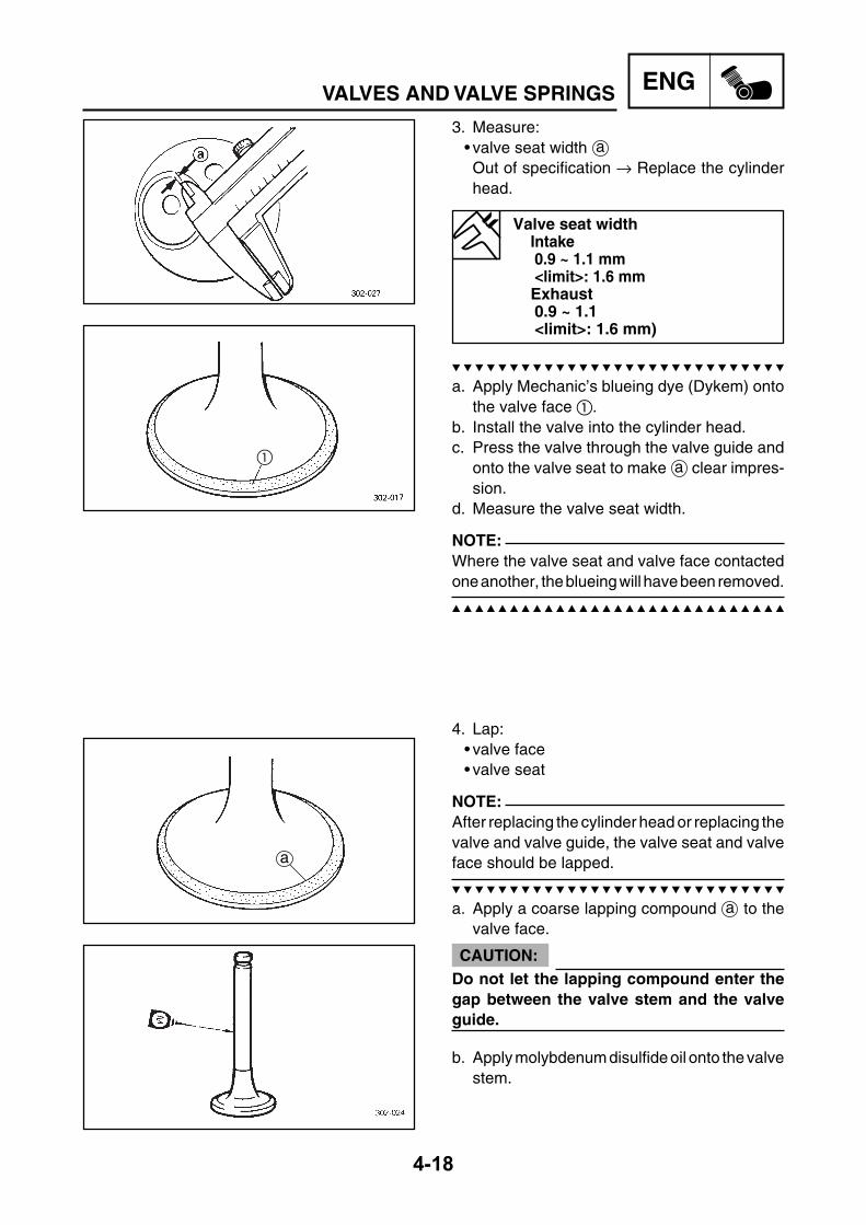
ENG
4-18
VALVES AND VALVE SPRINGS
3. Measure:• valve seat width aOut of specification → Replace the cylinderhead.
Valve seat widthIntake0.9 ~ 1.1 mm<limit>: 1.6 mmExhaust0.9 ~ 1.1<limit>: 1.6 mm)
a. Apply Mechanic’s blueing dye (Dykem) ontothe valve face .
b. Install the valve into the cylinder head.c. Press the valve through the valve guide and
onto the valve seat to make a clear impres-sion.
d. Measure the valve seat width.
NOTE:Where the valve seat and valve face contactedone another, the blueing will have been removed.
4. Lap:• valve face• valve seat
NOTE:After replacing the cylinder head or replacing thevalve and valve guide, the valve seat and valveface should be lapped.
a. Apply a coarse lapping compound a to thevalve face.
CAUTION:Do not let the lapping compound enter thegap between the valve stem and the valveguide.
b. Apply molybdenum disulfide oil onto the valvestem.
a

ENG
4-19
c. Install the valve into the cylinder head.d. Turn the valve until the valve face and valve
seat are evenly polished, then clean off all ofthe lapping compound.
NOTE:For the best lapping results, lightly tap the valveseat while rotating the valve back and forthbetween your hands.
e. Apply a fine lapping compound to the valveface and repeat the above steps.
f. After every lapping procedure, be sure toclean off all of the lapping compound from thevalve face and valve seat.
g. Apply Mechanic’s blueing dye (Dykem) ontothe valve face.
h. Install the valve into the cylinder head.i. Press the valve through the valve guide and
onto the valve seat to make a clear impres-sion.
j. Measure the valve seat width c again. If thevalve seat width is out of specification, refaceand lap the valve seat.
EAS00241
CHECKING THE VALVE SPRINGSThe following procedure applies to all of thevalve springs.1. Measure:
• valve spring free length aOut of specification → Replace the valvespring.
Valve spring free length (intakeand exhaust)
Valve spring41.94 mm<Limit>: 39.84mm
2. Measure:• compressed valve spring force aOut of specification → Replace the valvespring.b Installed length
VALVES AND VALVE SPRINGS

ENG
4-20
VALVES AND VALVE SPRINGS
EAS00245
INSTALLING THE VALVESThe following procedure applies to all of thevalves and related components.1. Deburr:
• valve stem end(with an oil stone)
2. Lubricate:• valve stem• oil seal(with the recommended lubricant)
Recommended lubricantMolybdenum disulfide oil
3. Install:• valve spring seat • valve stem seal • valve • valve spring • spring retainer (into the cylinder head)
NOTE:Install the valve spring with the larger pitch afacing up.
b Smaller pitch
Spring compressed pressure(intake and exhaust)
45.1 ~ 50.9 N
3. Measure:• valve spring tilt aOut of specification → Replace the valvespring.
Spring tilt limitIntake and exhaust valve spring2.5° / 1.9 mm
a
a
b

ENG
4-21
4. Install:• valve cotters
NOTE:Install the valve cotters by compressing thevalve spring with the valve spring compressor and attachment.
Valve spring compressor90890-04019
Attachment90890-04108
5. To secure the valve cotters onto the valvestem, lightly tap the valve tip with a soft-facehammer.
CAUTION:Hitting the valve tip with excessive forcecould damage the valve.
VALVES AND VALVE SPRINGS

ENG
4-22
CYLINDER AND PISTONEASM0025
CYLINDER AND PISTON
Removing the cylinder and piston Remove the parts in the order listed.Cylinder head Refer to “CYLINDER HEAD” section.
1 Cylinder bolts 22 Timing chain guide (lower) 13 Cylinder 14 Dowel pin 25 Cylinder gasket 16 Piston pin clip 27 Piston pin 18 Piston 19 Piston ring (top) 1
10 Piston ring (2nd) 111 Oil ring 1
For installation, reverse the removalprocedure.
Order Job/Part Q’ty Remarks
FWD
1
2
3
45
6
78
910 11
T.R12 Nm (1.2 m¥kg)
E

ENG
4-23
EAS00253
REMOVING THE CYLINDER AND PISTON1. Remove:
• piston pin clip • piston pin • piston
CAUTION:Do not use a hammer to drive the piston pinout.
NOTE:• Before removing the piston pin clip, cover thecrankcase opening with a clean rag to preventthe piston pin clip from falling into the crankcase.
• Before removing the piston pin, deburr thepiston pin clip’s groove and the piston’s pinbore area. If both areas are deburred and thepiston pin is still difficult to remove, remove itwith the piston pin puller.
Piston pin puller90890-01304
2. Remove:• top ring• 2nd ring• oil ring
NOTE:When removing a piston ring, open the end gapwith your fingers and lift the other side of the ringover the piston crown.
EAS00255
CHECKING THE CYLINDER AND PISTON1. Check:
• piston wall• cylinder wallVertical scratches → Rebore or replace thecylinder, and replace the piston and pistonrings as a set.
CYLINDER AND PISTON
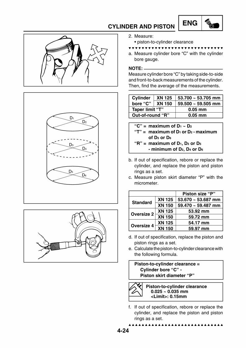
ENG
4-24
CYLINDER AND PISTON
D1
D2
D3
D4
D5D6
2. Measure:• piston-to-cylinder clearance
a. Measure cylinder bore “C” with the cylinderbore gauge.
NOTE:Measure cylinder bore “C” by taking side-to-sideand front-to-back measurements of the cylinder.Then, find the average of the measurements.
Cylinder XN 125 53.700 ~ 53.705 mmbore “C” XN 150 59.500 ~ 59.505 mmTaper limit “T” 0.05 mmOut-of-round “R” 0.05 mm
“C” = maximum of D1 ~ D2
“T” = maximum of D1 or D2 - maximumof D5 or D6
“R” = maximum of D1, D3 or D5
- minimum of D2, D4 or D6
b. If out of specification, rebore or replace thecylinder, and replace the piston and pistonrings as a set.
c. Measure piston skirt diameter “P” with themicrometer.
Piston size “P”
StandardXN 125 53.670 ~ 53.687 mmXN 150 59.470 ~ 59.487 mm
Oversize 2XN 125 53.92 mmXN 150 59.72 mm
Oversize 4XN 125 54.17 mmXN 150 59.97 mm
d. If out of specification, replace the piston andpiston rings as a set.
e. Calculate the piston-to-cylinder clearance withthe following formula.
Piston-to-cylinder clearance =Cylinder bore “C” -Piston skirt diameter “P”
Piston-to-cylinder clearance0.025 ~ 0.035 mm<Limit>: 0.15mm
f. If out of specification, rebore or replace thecylinder, and replace the piston and pistonrings as a set.

ENG
4-25
EAS00264
CHECKING THE PISTON RINGS
1. Measure:• piston ring side clearance Out of specification → Replace the piston andpiston rings as a set.
NOTE:Before measuring the piston ring side clearance,remove any carbon deposits from the piston ringgrooves and piston rings.
Piston ring side clearanceTop ring0.03 ~ 0.07 mm<Limit>: 0.12 mm2nd ring0.02 ~ 0.06<Limit>: 0.12 mm
2. Install:• piston ring(into the cylinder)
NOTE:Level the piston ring into the cylinder with thepiston crown.
a 0.5 mm
3. Measure:• piston ring end gap Out of specification → Replace the pistonring.
NOTE:The oil ring expander spacer’s end gap cannotbe measured. If the oil ring rail’s gap is excessive,replace all three piston rings.
Piston ring end gapTop ring 0.15 ~ 0.25 mm <Limit>: 0.50 mm2nd ring 0.15 ~ 0.30 mm <Limit>: 0.65 mmOil ring 0.20 ~ 0.70 mm
CYLINDER AND PISTON
a

ENG
4-26
CYLINDER AND PISTONEAS00265
CHECKING THE PISTON PIN1. Check:
• piston pinBlue discoloration / grooves → Replace thepiston pin and then check the lubricationsystem.
2. Measure:• piston pin outside diameter aOut of specification → Replace the piston pin.
Piston pin outside diameter14.991 ~ 15.000 mm
3. Calculate:• piston-pin-to-piston clearanceOut of specification → Replace the piston pinand piston as a set.
Piston-pin-to-piston clearance = Piston pin bore size b - Piston pin outside diameter a
Piston-pin-to-piston clearance0.002 ~ 0.022 mm
EAS00267
INSTALLING THE PISTON AND CYLINDER1. Install:
• top ring • 2nd ring • lower oil ring rail • upper oil ring rail • oil ring expander
NOTE:Be sure to install the piston rings so that themanufacturer’s marks or numbers face up.

ENG
4-27
2. Install:• piston • piston pin • piston pin clip
NOTE:• Lubricate the piston pin with engine oil.• Make sure the arrow mark a on the pistonpoints towards the exhaust side of the cylinder.
• Before installing the piston pin clip, cover thecrankcase opening with a clean rag to preventthe clip from falling into the crankcase.
3. Install:• gasket • dowel pins
4. Lubricate:• piston• piston rings• cylinder(with the recommended lubricant)
Recommended lubricantEngine oil
5. Offset:• piston ring end gaps
a Top ringb Lower oil ring railc Upper oil ring raild 2nd ring6. Install:
• cylinder
NOTE:• While compressing the piston rings with onehand, install the cylinder with the other hand.
• Pass the timing chain and timing chain guide(lower) through the timing chain cavity.
CYLINDER AND PISTON

ENG
4-28
CLUTCHEASM0026
CLUTCHCRANKCASE COVER
Removing the crankcase cover Remove the parts in the order listed.Side covers Refer SIDE COVERS AND SEAT”
section in chapter 3.1 Air filter crankcase cover 12 Air filter crankcase cover gasket 13 Air filter crankcase element 14 Crankcase cover protector 15 Crankcase cover (left) 16 Crankcase cover gasket 1
For installation, reverse the removalprocedure.
Order Job/Part Q’ty Remarks
FWD1
2
3
4
5
6
T.R10 Nm (1.0 m¥kg)
T.R9 Nm (0.9 m¥kg)
T.R10 Nm (1.0 m¥kg)

ENG
4-29
EASM0027
V-BELT, CLUTCH AND SECONDARY/PRIMARY SHEAVE
Removing the V-belt, clutch and Remove the parts in the order listed.secondary/primary sheave
1 Nut/plain washer/washer 1/1/1 Refer to “REMOVING THE PRIMARY2 Primary fixed sheave 1 SHEAVE” section.3 Nut 1 Refer to “REMOVING THE SECONDARY4 Clutch housing 1 SHEAVE AND V-BELT” section.5 Clutch assembly 1 Refer to “INSTALLING THE6 V-belt 1 SECONDARY SHEAVE” section.7 Washer 18 Primary sliding sheave 19 Collar 1
Refer to “ASSEMBLING THE PRIMARY10 Cam 1 SHEAVE” section.11 Weight 6
12 Slider 313 Oil seal 2
For installation, reverse the removalprocedure.
V-BELT, CLUTCH AND SECONDARY / PRIMARYSHEAVE
Order Job/Part Q’ty Remarks
FWD
12
43
56
7
8
9
12
1113
13
10
T.R55 Nm (5.5 m¥kg)
T.R60 Nm (6.0 m¥kg)

ENG
4-30
V-BELT, CLUTCH AND SECONDARY / PRIMARYSHEAVE
EASM0028
SECONDARY SHEAVE
Disassembling the secondary Disassemble the parts in the order listed.sheave
Nut 1 Refer to “DISASSEMBLING THE Clutch carrier 1 SECONDARY SHEAVE” section. Clutch shoe spring 3 Refer to “INSTALLING THE Compression spring 1 SECONDARY SHEAVE” section. Spring seat 1
Guide pin 3 Secondary sliding sheave 1
Refer to “INSTALLING THE O-ring 2 SECONDARY SHEAVE” section. Oil seal 2
Secondary fixed sheave 1For assembly, reverse the disassemblyprocedure.
Order Job/Part Q’ty Remarks
FWD
T.R90 Nm (9.0 m¥kg)
* *
* *
* *
* *
LS
Apply BEL-RAY assembly lube ®**

ENG
4-31
REMOVING THE PRIMARY SHEAVE1. Remove:
• nut (primary sheave)• plate washer• primary fixed sheave
NOTE:Loosen the nut (primary fixed sheave) whileholding the primary fixed sheave with the rotorholder .
Rotor holder90890-01235
REMOVING THE SECONDARY SHEAVEAND V-BELT1. Remove:
• nut (secondary sheave)• clutch housing
NOTE:Loosen the nut (secondary sheave) while holdingthe clutch housing with the sheave holder .
Sheave holder90890-01701
2. Remove:• nut (clutch carrier)
CAUTION:Do not remove the nut (clutch carrier) yet.
NOTE:Loosen the nut (clutch carrier) one turn using thelocknut wrench while holding the clutch carrierwith the rotor holder .
Rotor holder90890-01235
V-BELT, CLUTCH AND SECONDARY / PRIMARYSHEAVE
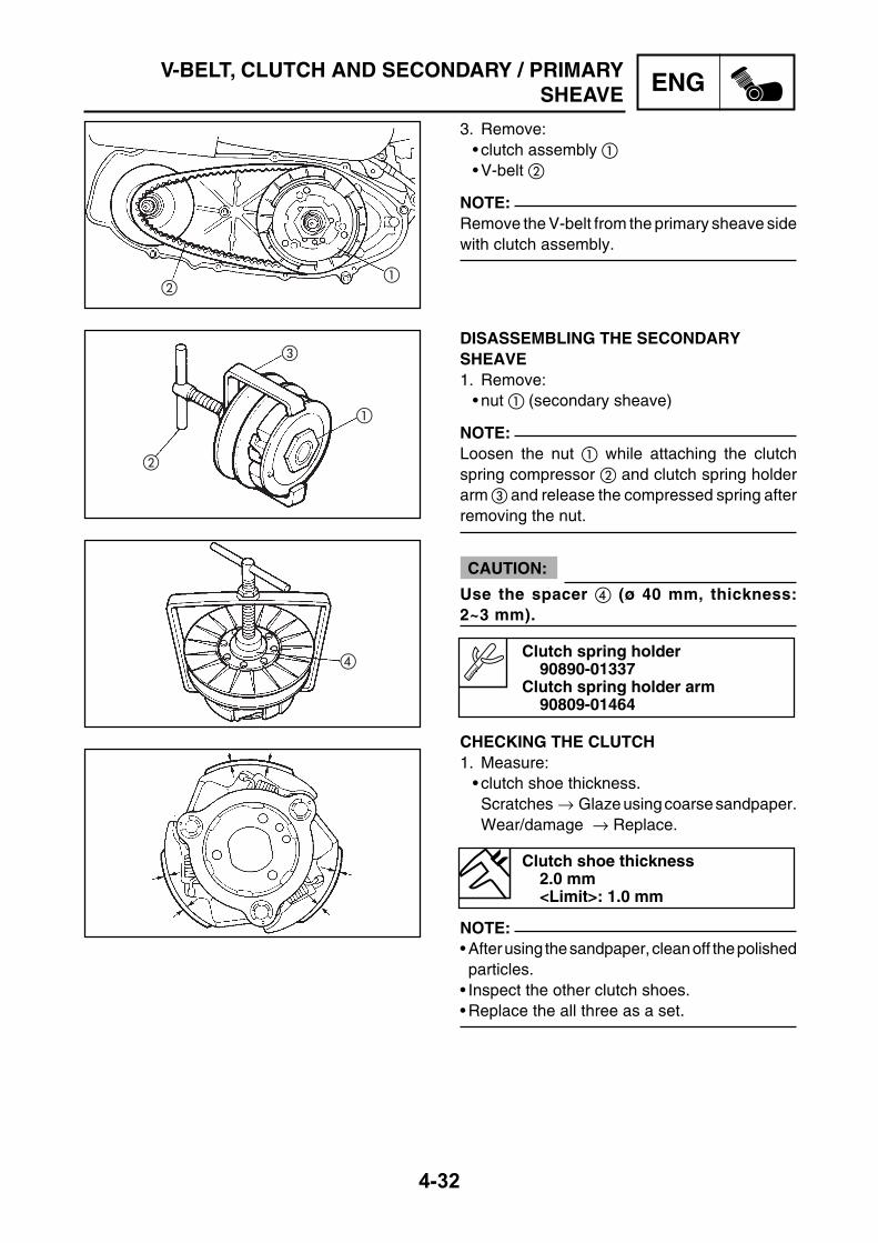
ENG
4-32
V-BELT, CLUTCH AND SECONDARY / PRIMARYSHEAVE
3. Remove:• clutch assembly • V-belt
NOTE:Remove the V-belt from the primary sheave sidewith clutch assembly.
DISASSEMBLING THE SECONDARYSHEAVE1. Remove:
• nut (secondary sheave)
NOTE:Loosen the nut while attaching the clutchspring compressor and clutch spring holderarm and release the compressed spring afterremoving the nut.
CAUTION:
Use the spacer (ø 40 mm, thickness:2~3 mm).
Clutch spring holder90890-01337
Clutch spring holder arm90809-01464
CHECKING THE CLUTCH1. Measure:
• clutch shoe thickness.Scratches → Glaze using coarse sandpaper.Wear/damage → Replace.
Clutch shoe thickness2.0 mm<Limit>: 1.0 mm
NOTE:• After using the sandpaper, clean off the polishedparticles.
• Inspect the other clutch shoes.• Replace the all three as a set.

ENG
4-33
V-BELT, CLUTCH AND SECONDARY / PRIMARYSHEAVE
EAS00290
CHECKING THE CLUTCH HOUSING1. Check:
• clutch housingDamage/wearr → Replace.
2. Measure:• clutch housing inside diameter aOut of specification → Replace the clutchhousing.
Clutch housing inside diameterXN125: 120 mmXN150: 135 mm<Limit XN125>: 120.5 mm<Limit XN150>: 130.5 mm
EAS00282
CHECKING THE CLUTCH SPRINGSThe following procedure applies to all of theclutch springs.1. Check:
• clutch springDamage → Replace the clutch springs as aset.
2. Measure:• clutch spring free lengthOut of specification → Replace the clutchsprings as a set.
Clutch spring free lengthXN125: 28 mmXN150: 31.3 mm
CHECKING THE V-BELT1. Check:
• V-belt Cracks/wear/scaling/chipping → Replace.Oil/grease → Check the secondary sheave.
2. Measure:• V-belt width Out of specification → Replace.
V-belt width22 mm<Limit>: 19 mm
a

ENG
4-34
V-BELT, CLUTCH AND SECONDARY / PRIMARYSHEAVE
CHECKING THE WEIGHTS1. Check:
• weight minimum outside diameterCracks/wear/scaling/chipping → Replace.Out of specification → Replace.
Weight out side diameter20.0 mm<Limit>: 19.5 mm
CHECKING THE SECONDARY SHEAVE1. Check:
• secondary fixed sheave smooth operation• secondary sliding sheave smooth operationScratches/damage → Replace as a set.
2. Check:• Torque cam groove Wear/damage → Replace.
3. Check:• Guide pin Wear/damage → Replace.
ASSEMBLING THE PRIMARY SHEAVE1. Clean:
• primary sliding sheave face • primary fixed sheave face • collar • weight • primary sliding sheave cam face
2. Install:• weight • collar
3. Install:• slider • cam

ENG
4-35
3. Install:• guide pin
4. Apply:• BEL-RAY assembly lube ®(to the guide pin sliding groove , and oil seal )
5. Install:• secondary sheave complete • compression spring• clutch carrier
NOTE:Temporarily tighten the nut while attachingthe clutch spring holder and clutch springholder arm and compress the spring.
CAUTION:
Use the spacer (ø 40 mm, thickness: 2~3 mm).
Clutch spring holder90890-01337
Clutch spring holder arm90890-01464
V-BELT, CLUTCH AND SECONDARY / PRIMARYSHEAVE
E
E
INSTALLING THE SECONDARY SHEAVE1. Apply:
• BEL-RAY assembly lube ®(to the secondary sliding sheave inner sur-face, grease nipple groove, and oil seals)
• BEL-RAY assembly lube ®(to the bearings, oil seals and inner surface ofthe secondary fixed sheave)
2. Install:• secondary sliding sheave
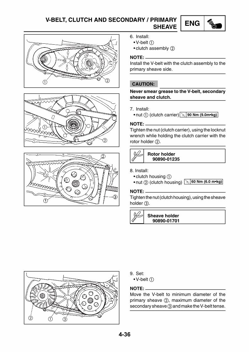
ENG
4-36
V-BELT, CLUTCH AND SECONDARY / PRIMARYSHEAVE
T.R 90 Nm (9.0m•kg)
T.R 60 Nm (6.0 m•kg)
6. Install:• V-belt • clutch assembly
NOTE:Install the V-belt with the clutch assembly to theprimary sheave side.
CAUTION:
Never smear grease to the V-belt, secondarysheave and clutch.
7. Install:• nut (clutch carrier)
NOTE:Tighten the nut (clutch carrier), using the locknutwrench whlie holding the clutch carrier with therotor holder .
Rotor holder90890-01235
8. Install:• clutch housing • nut (clutch housing)
NOTE:Tighten the nut (clutch housing), using the sheaveholder .
Sheave holder90890-01701
9. Set:• V-belt
NOTE:Move the V-belt to minimum diameter of theprimary sheave , maximum diameter of thesecondary sheave and make the V-belt tense.

ENG
4-37
EASM0029
STARTER CLUTCH AND GENERATORMAGNETO COVER AND STATOR COIL
Removing the magneto cover and Remove the parts in the order listed.stator coilSide cover Refer to “SIDE COVERS AND SEAT”
section in chapter 3.1 Flywheel lead coupler 22 Flywheel cover 13 Nut 14 Washer 25 Rotor 16 Stator fixing screws 37 Woodruf key 18 Stator 19 Pick up coil screw 2
10 Pick up coil 1For installation, reverse the removalprocedure.
STARTER CLUTCH AND GENERATOR
Order Job/Part Q’ty Remarks
FWD
12
34
56
8
10
7
9
T.R70 Nm (7,0 m•kg)
T.R7 Nm (0,7 m•kg)
T.R7 Nm (0,7 m•kg)

ENG
4-38
STARTER CLUTCH AND GENERATOREASM0030
STARTER CLUTH
Removing the starter clutch Remove the parts in the order listed.1 Gear retainer plane 12 Washer 13 Idle gear 14 Washer 15 Starter one way cluth 16 Collar 17 Starter wheel gear 1
For installation, reverse the removalprocedure.
Order Job/Part Q’ty Remarks
FWD
1
2
5
7 6
43
T.R7 Nm (0,7 m•kg)
T.R65 Nm (6,5 m•kg)

ENG
4-39
EAS00348
CHECKING THE STARTER CLUTCH1. Check:
• starter clutch idle gear• starter clutch wheel gear• starter one way clutchChips/pitting/roughness/wear → Replace thedefective part(s).
2. Check:• starter clutch operation
a. Install the starter clutch drive gear onto thestarter clutch and hold the starter clutch.
b. When turning the starter clutch drive gearcounter-clockwise, the starter clutch and thestarter clutch drive gear should engage,otherwise the starter clutch is faulty and mustbe replaced.
c. When turning the starter clutch drive gearclockwise, it should turn freely, otherwise thestarter clutch is faulty and must be replaced.
STARTER CLUTCH AND GENERATOR
EAS00354
INSTALLING THE GENERATOR1. Install:
• woodruff key • generator rotor • washers • generator rotor nut
NOTE:• Clean the tapered portion of the crankshaft andthe generator rotor hub.
• When installing the generator rotor, make surethe woodruff key is properly seated in the keyway of the crankshaft.
2. Tighten:• generator rotor nut
NOTE:While holding the generator rotor with the rotorholder , tighten the generator rotor bolt.
Rotor holder90890-01235
321050
T.R 70 Nm (7.0m•kg)

ENG
4-40
OIL PUMPEASM0031
OIL PUMP
Removing the oil pump Remove the parts in the order listed.Drain Engine oil Refer to “CHANGING THE ENGINE
OIL” section in chapter 3.Flywheel Refer to “STARTER CLUTCH AND
GENERATOR” section.1 Oil pump cover fixing screws 32 Oil pump cover 13 Oil pump clip 14 Washer 15 Oil pump gear 16 Oil pump gear dowel pin 17 Oil pump fixing screws 28 Oil pump assembly 1
For installation, reverse the removalprocedure.
Order Job/Part Q’ty Remarks
FWD
2
1
3 45
68
7T.R65 Nm (6,5 m•kg)
T.R7 Nm (0,7 m•kg)

ENG
4-41
OIL PUMPEAS00363
CHECKING THE OIL PUMP1. Check:
• oil pump drive gear• oil pump driven gear • oil pump housing• oil pump housing coverCracks/damage/wear → Replace thedefective part(-s).
2. Measure:• inner-rotor-to-outer-rotor-tip clearance A• outer-rotor-to-oil-pump-housing clearance B• Pump housing-to-rotors clearance COut of specification → Replace the oil pump.
Inner rotor Outer rotor Oil pump housing
Inner-rotor-to-outer-rotor-tipclearance
limit: 0.15 mmOuter-rotor-to-oil-pump-housingclearance
limit: 0.15 mmPump housing-to-rotors clearance
limit: 0.17 mm
3. Check:• oil pump operationRough movement → Replace the defectivepart(s).
A
B
C

ENG
4-42
CRANKCASE AND CRANKSHAFTEASM0032
CRANKCASE AND CRANKSHAFT
Removing the crankcase and Remove the parts in the order listed.crankshaftEngine Refer to “ENGINE” section.Cylinder head Refer to “CYLINDER HEAD” section.Cylinder and piston Refer to “CYLINDER AND
PISTON” section.V-belt, cluth, secondary/primary sheave Refer to “V-BELT, CLUTCH AND
SECONDARY/PRIMARY SHEAVE”section.
CDI magneto Refer to ”STARTER CLUTCHAND GENERATOR” section.
Oil pump Refer to “OIL PUMP” section.Water pump Refer to “WATER PUMP” section in
chapter 5.Rear wheel Refer to “REAR WHEEL AND BRAKE”
section in chapter 7.
Order Job/Part Q’ty Remarks
FWD
3 4
5
6
8
1
T.R9 Nm (0.9 m¥kg)
T.R9 Nm (0.9 m¥kg)
E
E
2
7
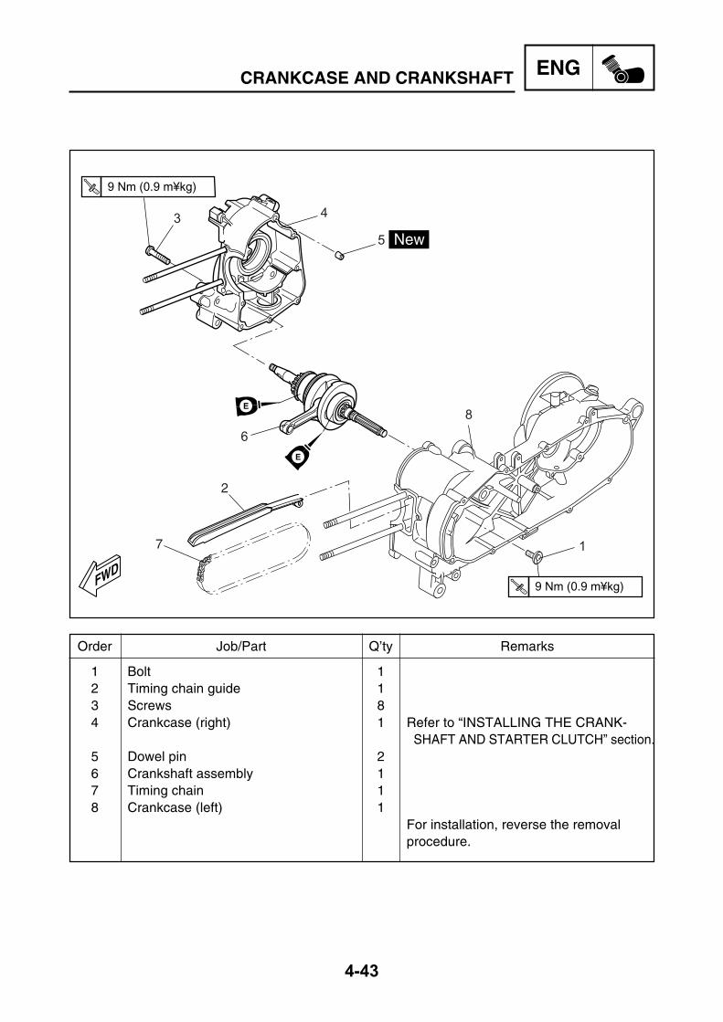
ENG
4-43
1 Bolt 12 Timing chain guide 13 Screws 84 Crankcase (right) 1 Refer to “INSTALLING THE CRANK-
SHAFT AND STARTER CLUTCH” section.5 Dowel pin 26 Crankshaft assembly 17 Timing chain 18 Crankcase (left) 1
For installation, reverse the removalprocedure.
CRANKCASE AND CRANKSHAFT
Order Job/Part Q’ty Remarks
FWD
3 4
5
6
8
1
T.R9 Nm (0.9 m¥kg)
T.R9 Nm (0.9 m¥kg)
E
E
2
7
ENG
4-44
CRANKCASE AND CRANKSHAFTEAS00385
DISASSEMBLING THE CRANKCASE1. Remove:
• crankcase bolts
NOTE:Loosen each bolt 1/4 of a turn at a time, in stagesand in a crisscross pattern. After all of the boltsare fully loosened, remove them.
2. Remove:• right crankcase
CAUTION:Tap on one side of the crankcase with a soft-face hammer. Tap only on reinforced por-tions of the crankcase, not on the crankcasemating surfaces. Work slowly and carefullyand make sure the crankcase halvesseparate evenly.
3. Remove:• timing chain from crankshaft sprocket
EAS00388
REMOVING THE CRANKSHAFTASSEMBLY1. Remove:
• crankshaft assembly
CAUTION:
Tap on one side of the crankshaft with a soft-face hammer. Work slowly and carefully andmake sure the crankshaft separate evenlyfrom the crankcase.
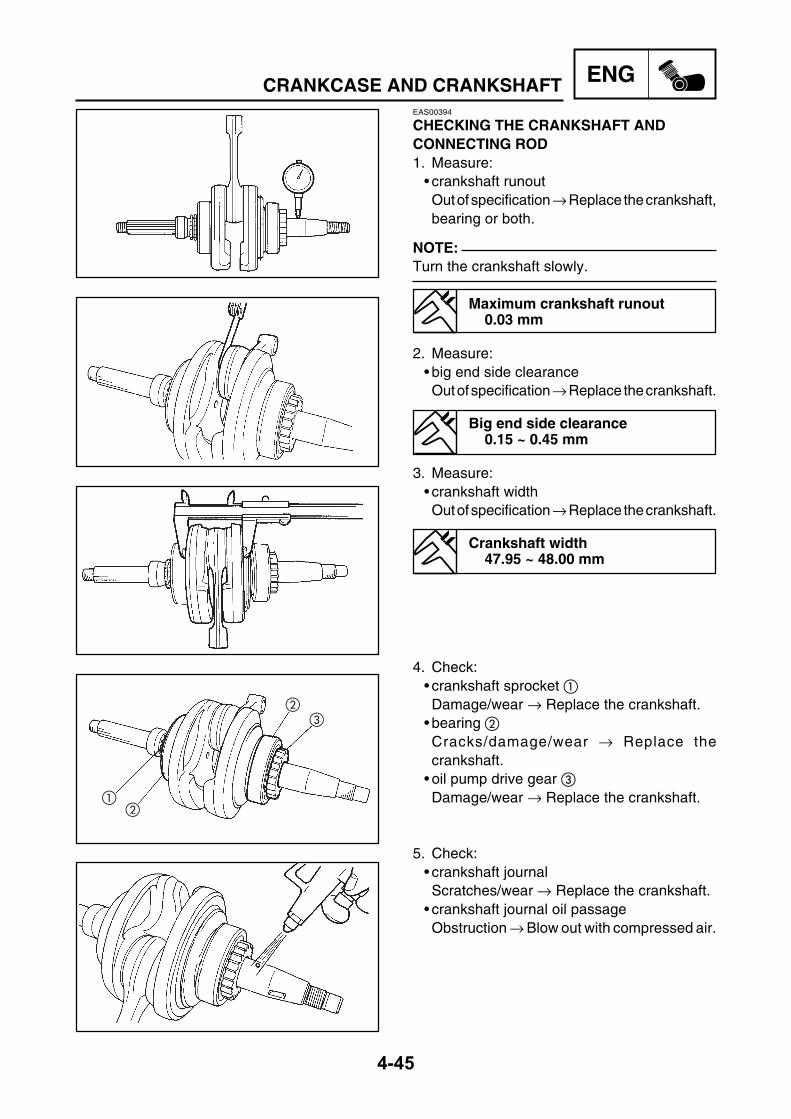
ENG
4-45
EAS00394
CHECKING THE CRANKSHAFT ANDCONNECTING ROD1. Measure:
• crankshaft runoutOut of specification → Replace the crankshaft,bearing or both.
NOTE:Turn the crankshaft slowly.
Maximum crankshaft runout0.03 mm
2. Measure:• big end side clearanceOut of specification → Replace the crankshaft.
Big end side clearance0.15 ~ 0.45 mm
3. Measure:• crankshaft widthOut of specification → Replace the crankshaft.
Crankshaft width47.95 ~ 48.00 mm
4. Check:• crankshaft sprocket Damage/wear → Replace the crankshaft.
• bearing Cracks/damage/wear → Replace thecrankshaft.
• oil pump drive gear Damage/wear → Replace the crankshaft.
5. Check:• crankshaft journalScratches/wear → Replace the crankshaft.
• crankshaft journal oil passageObstruction → Blow out with compressed air.
CRANKCASE AND CRANKSHAFT

ENG
4-46
CRANKCASE AND CRANKSHAFTEAS00399
CHECKING THE CRANKCASE1. Thoroughly wash the crankcase halves in a
mild solvent.2. Thoroughly clean all the gasket surfaces and
crankcase mating surfaces.3. Check:
• crankcaseCracks/damage → Replace.
• oil delivery passagesObstruction → Blow out with compressed air.
EAS00401
CHECKING THE BEARINGS AND OILSEALS1. Check:
• bearings Clean and lubricate the bearings, then rotatethe inner race with your finger.Rough movement → Replace.
2. Check:• oil seals Damage/wear → Replace.
EAS00402
CHECKING THE CIRCLIPS AND WASHERS1. Check:
• circlips Bends/damage/looseness → Replace.
• washers Bends/damage → Replace.
EAS00408
INSTALLING THE CRANKSHAFT1. Install:
• crankshaft assembly• timing chain
CAUTION:
To avoid scratching the crankshaft and toease the installation procedure, apply areaseonto the oil seal lips and apply engine oil ontoeach bearing.

ENG
4-47
CRANKCASE AND CRANKSHAFTEAS00416
ASSEMBLING THE CRANKCASE1. Apply:
• sealant(onto the crankcase mating surfaces)
Yamaha bond No. 121590890-85505
NOTE:Do not allow any sealant to come into contactwith the oil gallery.
2. Install:• dowel pins
3. Install:• crankshaft
4. Install:• timing chain
5. Install:• left crankcase(onto the right crankcase)
NOTE:Tap lightly on the left crankcase with a soft-facehammer.
6. Install:• crankcase bolts
7. Apply:• engine oil(onto the crankshaft bearings, conrod andcrank pin)
8. Check:• crankshaft operationRough movement → Repair.
• timing chain position
T.R 9 Nm (0.9m•kg)

ENG
4-48
EASM0033
TRANSMISSION
Removing the transmission Remove the parts in the order listed.Rear wheel Refer to “REAR WHEEL AND
BRAKE” section in chapter 7.Crankcase cover (left) Refer to “V-BELT, CLUTH AND
SECONDARY/PRIMARY SHEAVE”section.
Drain the transmission oil Refer to “TRANSMISSON OILREPLACEMENT” section in chapter 3.
1 Transmission cover screws 62 Transmission case cover 13 Gasket 14 Dowel pin 2 Refer to “INSTALLING THE CRANK-
SHAFT AND STARTER CLUTCH” section.5 Primary drive gear 16 Plain washer 17 Secondary drive gear axle 1
TRANSMISSION
Order Job/Part Q’ty Remarks
FWD2
1
3
4
6
7
9
5
T.R6.5 Nm (0,65 m•kg)
EE
E
E
E
G
G
LS
8

ENG
4-49
8 Idle gear 1
9 Main axle 1For installation, reverse the removalprocedure.
TRANSMISSION
Order Job/Part Q’ty Remarks
FWD2
1
3
4
6
7
9
5
T.R6.5 Nm (0,65 m•kg)
EE
E
E
E
G
G
LS
8

5COOL

CHAPTER 5.COOLING SYSTEM
RADIATOR ....................................................................................................5-1CHECKING THE RADIATOR ..................................................................5-3INSTALLING THE RADIATOR ................................................................5-3
THERMOSTAT ..............................................................................................5-4CHECKING THE THERMOSTAT ............................................................5-5INSTALLING THE THERMOSTAT ..........................................................5-5
WATER PUMP ...............................................................................................5-6CHECKING THE WATER PUMP .............................................................5-7INSTALLING THE WATER PUMP ...........................................................5-7
COOL

COOL
5-1
RADIATOREASM0034
COOLING SYSTEMRADIATOR
Drain coolant Refer to “CHANGING THE COOLANT”section in chapter 3.
Front cover Refer to “FRONT COVER, INNERPANEL AND INNER FRONT COVER”section in chapter 3.
Footrest board Refer to “FOOTREST BOARD ANDUNDER COVER” section in chapter 3.
I Disconnet:1 Fan motor coupler 12 Thermo switch connectors 4II Unplug:3 Radiator outlet hose 14 Radiator inlet hose 15 Radiator filler hose 1III Untight:6 Radiator bracket (frame) 1
Order Job/Part Q’ty Remarks
1
2
3
4
2
8
7
6
5

COOL
5-2
RADIATOR
IV Remove:7 Radiator 18 Radiator fan 1
For installation, reverse the removalprocedure.
Order Job/Part Q’ty Remarks
1
2
3
4
2
8
7
6
5
NOTE:Avoid the radiator of falling

COOL
5-3
RADIATOREAS00455
CHECKING THE RADIATOR1. Check:
• radiator fins Obstruction → Clean.Apply compressed air to the rear of theradiator.Damage → Repair or replace.
NOTE:Straighten any flattened fins with a thin, flat-head screwdriver.
2. Check:• radiator hoses• radiator pipesCrack/damage → Replace.
3. Check:• radiator capCracks/damage → Replace.
4. Check:• radiator fanDamage → Replace.Malfunction → Check and repair.Refer to “COOLING SYSTEM” section inchapter 8.
EAS00456
INSTALLING THE RADIATOR1. Fill:
• cooling system(with the specified amount of therecommended coolant)Refer to “CHANGING THE COOLANT” sec-tion in chapter 3.
2. Check:• cooling systemLeaks → Repair or replace any faulty part.
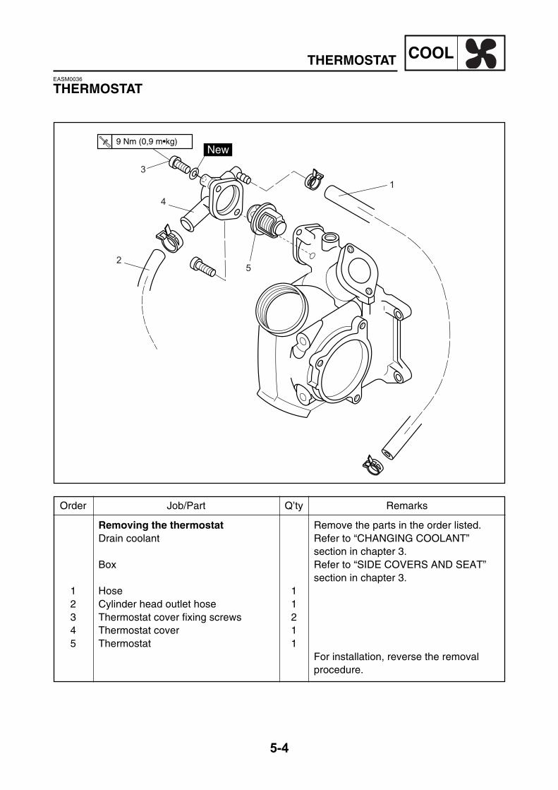
COOL
5-4
THERMOSTATEASM0036
THERMOSTAT
Removing the thermostat Remove the parts in the order listed.Drain coolant Refer to “CHANGING COOLANT”
section in chapter 3.Box Refer to “SIDE COVERS AND SEAT”
section in chapter 3.1 Hose 12 Cylinder head outlet hose 13 Thermostat cover fixing screws 24 Thermostat cover 15 Thermostat 1
For installation, reverse the removalprocedure.
Order Job/Part Q’ty Remarks
1
2
3
4
5
T.R9 Nm (0,9 m•kg)

COOL
5-5
THERMOSTATEAS00462
CHECKING THE THERMOSTAT1. Check:
• thermostat Does not open at 80.5 ~ 83.5°C → Replace.
a. Suspend the thermostat in a container filledwith water.
b. Slowly heat the water.c. Place a thermometer in the water.d. While stirring the water, observe the ther-
mostat and thermometer ’s indicatedtemperature.
Thermometer Water Thermostat Container A Fully closed B Fully open
NOTE:If the accuracy of the thermostat is in doubt,replace it. A faulty thermostat could cause seriousoverheating or overcooling.
2. Check:• thermostat housing cover • thermostat housingCracks/damage → Replace.
EASM0037
INSTALLING THE THERMOSTAT1. Install:
• thermostat• thermostat cover• hoses
3mm
B
A

COOL
5-6
WATER PUMPEASM0035
WATER PUMP
Order Job/Part Q’ty Remarks
1
4
3
2
T.R10 Nm (1.0m¥kg)
T.R7 Nm (0.7m¥kg)
T.R7 Nm (0.7m¥kg)
3
3
3
LS
Removing the water pump Remove the parts in the order listed.Drain coolant Refer to “CHANGING THE COOLANT”
section in chapter 3.1 Pump inlet hose 12 Pump outlet hose 13 Water pump fixing screws 34 Water pump assembly 1
Disassembling water pump Water pump mounting screws 4 Bleed screw with copper washer 1/1 Water pump inner cover 1 O-ring 1 Water pump cover/gasket 1/1 Impeller shaft 1 Dowel pin 1
For installation, reverse the removal procedure.
NOTE:Follow the arrows

COOL
5-7
WATER PUMPEAS00472
CHECKING THE WATER PUMP1. Check:
• O-ring Damage/wear → Replace.
• oil seal Damage/wear → Replace the water pumphousing assembly.
NOTE:The mark “water side” on the oil seal should beinstalled outward.
2. Check:• impellerCracks/damage/wear → Replace the waterpump housing assembly.
• water pump housingCracks/damage → Replace the water pumphousing assembly.
EAS00477
INSTALLING THE WATER PUMP
NOTE:Always replace the entire water pump assembly.
1. Install:• impeller• water pump inner cover• screw
NOTE:After installation, check that the impeller shaftrotates smoothly.
2. Install:• O-ring
NOTE:Lubricate the O-ring with a thin coat of lithiumsoap base grease.
LS
T.R 7 Nm (0.7m•kg)

COOL
5-8
WATER PUMP
3. Install:• dowel pin• gasket • water pump housing cover• screws• copper washer • bleed screw
NOTE:Do not forget to install the copper washer on thebleed screw.
T.R 7 Nm (0.7m•kg)
T.R 7 Nm (0.7m•kg)

6CARB

CHAPTER 6.CARBURETOR
CARBURETOR ..............................................................................................6-1CARBURETOR REMOVAL .....................................................................6-1CARBURETOR DISASSEMBLY ..............................................................6-2CHECKING THE CARBURETOR ............................................................6-3ASSEMBLING THE CARBURETOR .......................................................6-5MEASURING AND ADJUSTING THE FUEL LEVEL ...............................6-6CHECKING THE AUTOCHOKE UNIT .....................................................6-6CHECKING THE FUEL COOK ................................................................6-7
CARB

CARB
6-1
CARBURETOREASM0038
CARBURETORCARBURETOR
Removing the carburetor Remove the parts in the order listed.Side cover
Refer to “SIDE COVERS AND SEAT”Fuel tank
in chapter section 3.Box
I Disconnect:1 Auto choke coupler 12 Carburetor heater connectors 2II Unplug:3 Fuel hose 1III Remove:4 Throttle cable 15 Fixing clip 26 Air duct 17 Carburetor assembly 1
For installation, reverse the removalprocedure.
CAUTION:
Do not bend the air filter joint clampwhen installing the carburetor.
Order Job/Part Q’ty Remarks
4
6
5
57
31
2

CARB
6-2
CARBURETOR
Carburetor disassembly Remove the parts in the order listed. Auto choke unit 1 Throttle stop screw set 1 Pilot screw set 1 Diaphragm cover/spring 1/1 Throttle valve 1 Needle set 1 Accelerating pump lever 1 Float chamber/gasket 1/1 Float axle 1/1
Float 1 Needle jet 1 Main jet 1 Pilot jet 1 Main nozzle 1 Heater assembly 1 For assembly, reverse the disassembly procedure.
Order Job/Part Q’ty Remarks
Y
Q
U
I
R
T
e
qw
P
O
Y
E
W
NOTE:Remove the float pin from the side of thearrow.

CARB
6-3
EAS00485
CHECKING THE CARBURETOR1. Check:
• carburetor body • float chamber• jet housingCracks/damage → Replace.
2. Check:• fuel passagesObstruction → Clean.
a. Wash the carburetor in a petroleum-basedsolvent. Do not use any caustic carburetorcleaning solution.
b. Blow out all of the passages and jets withcompressed air.
CARBURETOR
12
3. Check:• float chamber body Dirt → Clean.
4. Check:• float chamber rubber gasketCracks/damage/wear → Replace.
5. Check:• float Damage → Replace.
6. Check:• needle valve • needle valve seat Damage/obstruction/wear → Replace theneedle valve, needle valve seat and O-ring asa set.
7. Check:• o-ring Damage/wear → Replace the needle valve,needle valve seat and o-ring as a set.
8. Check:• piston valveDamage/scratches/wear → Replace.
• Piston valve diaphragmCracks/Tears → Replace.
322006
1
2
1

CARB
6-4
CARBURETOR
9. Check:• vacuum chamber cover• piston valve spring• jet needle holderCracks/damage → Replace.
322012
10. Check:• jet needle kit• main jet • needle jet • pilot jet • pilot screwBends/damage/wear → Replace.Obstruction → Replace.
322015
11. Check:• piston valve movementInsert the piston valve into the carburetorbody and move it up and down.Tightness → Replace the throttle valve.
12. Check:• starter plunger• starter plunger springBends/cracks/damage → Replace.
13. Check:• hose jointsCracks/damage → Replace.
14. Check:• vacuum hoses• fuel hosesCracks/damage/wear → Replace.Obstruction → Clean.Blow out the hoses with compressed air.
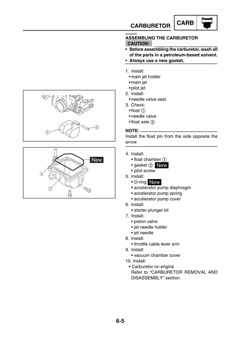
CARB
6-5
CARBURETOREAS00487
ASSEMBLING THE CARBURETOR
• Before assembling the carburetor, wash allof the parts in a petroleum-based solvent.
• Always use a new gasket.
1. Install:• main jet holder• main jet• pilot jet
2. Install:• needle valve seat
3. Check:• float • needle valve• float axle
NOTE:Install the float pin from the side opposite thearrow.
4. Install:• float chamber • gasket • pilot screw
5. Install:• O-ring• accelerator pump diaphragm• accelerator pump spring• accelerator pump cover
6. Install:• starter plunger kit
7. Install:• piston valve• jet needle holder• jet needle
8. Install:• throttle cable lever arm
9. Install:• vacuum chamber cover
10. Install:• Carburetor on engineRefer to “CARBURETOR REMOVAL ANDDISASSEMBLY” section.
CAUTION:
2 1
1
W

CARB
6-6
CARBURETOR
EAS00503
CHECKING THE AUTOCHOKE UNIT
NOTE:When checking the autochoke unit, the ambienttemperature must be lower than 45°C.
1. Remove:• carburetorRefer to "CARBURETOR REMOVAL" section.
EAS00499
MEASURING AND ADJUSTING THE FUELLEVEL1. Measure:
• fuel level aOut of specification → Adjust
Fuel level (below the float chambermating surface)
5 ~ 6 mm
a. Stand the scooter on a level surface.b. Place the scooter on a suitable stand to
ensure that the scooter is standing straightup.
c. Install the fuel level gauge onto the fueldrain pipe .
Fuel level gauge90890-01312
d. Loosen the fuel drain screw .e. Hold the fuel level gauge vertically next to the
float chamber.f. Measure the fuel level a .
2. Adjust:• fuel level
a. Remove the carburetor.b. Check the needle valve seat and needle
valve.c. If either is worn, replace them as a set.d. If both are fine, adjust the float level by slightly
bending the float tang.e. Install the carburetor.f. Measure the fuel level again.g. Repeat steps (a) to (f) until the fuel level is
within specification.

CARB
6-7
CARBURETOR
2. Check:• autochoke unit
a. Connect ø 3.3 mm hose to the starter airpassage and blow into the hose.
NOTE:When the starter plunger is open, air shouldcome out of the other side of the starter airpassage.
Starter plunger opens →→→→→Perform step.Starter plunger closes →→→→→Replace the
autochoke unit.
3. Check:• autochoke unit
a. Connect the autochoke unit leads to a12.0V battery for five minutes.
Positive battery lead →→→→→ blackNegative battery lead →→→→→ black
b. Connect ø 3.3-mm hose to the starter airpassage and blow into the hose.
Starter plunger opens → → → → → Replace the autochoke unit.
Starter plunger closes → → → → → Autochoke unit is OK.
EAS00505
CHECKING THE FUEL COCK1. Check:
• fuel cockCracks/damage/wear → Replace.
2. Check:• fuel cock strainer(with compressed air)Dirt/obstruction → Clean.Damage → Replace.

7CHAS

CHAPTER 7.CHASSIS
FRONT WHEEL AND BRAKE DISC .............................................................7-1REMOVING THE FRONT WHEEL ..........................................................7-2CHECKING THE FRONT WHEEL ...........................................................7-3CHECKING THE BRAKE DISC ...............................................................7-4CHECKING THE SPEEDOMETER GEAR UNIT .....................................7-5ASSEMBLING THE FRONT WHEEL ......................................................7-5INSTALLING THE FRONT WHEEL .........................................................7-6ADJUSTING THE FRONT WHEEL STATIC BALANCE ..........................7-6
REAR WHEEL AND BRAKE ........................................................................7-8CHECKING THE REAR WHEEL .............................................................7-9CHECKING THE REAR BRAKE ..............................................................7-9ASSEMBLING THE BRAKE SHOE PLATE ...........................................7-10INSTALLING THE REAR WHEEL .........................................................7-10ADJUSTING THE REAR WHEEL STATIC BALANCE .......................... 7-11
FRONT BRAKE ...........................................................................................7-12FRONT BRAKE PADS ...........................................................................7-12REPLACING THE FRONT BRAKE PADS .............................................7-13FRONT BRAKE MASTER CYLINDER ..................................................7-15MASTER CYLINDER .............................................................................7-16DISASSEMBLING THE FRONT BRAKE MASTER CYLINDER ............7-17CHECKING THE FRONT BRAKE MASTER CYLINDER ......................7-17ASSEMBLING AND INSTALLING THE FRONT BRAKE MASTERCYLINDER - WARNING ........................................................................7-18DISASSEMBLING THE FRONT BRAKE CALIPER...............................7-19CHECKING THE FRONT BRAKE CALIPER .........................................7-20ASSEMBLING AND INSTALLING THE FRONT BRAKE CALIPER ......7-21
FRONT FORK ..............................................................................................7-23FRONT FORK DISASSEMBLY .............................................................7-24REMOVING THE FRONT FORK LEGS ................................................7-25DISASSEMBLING THE FRONT FORK LEGS .......................................7-25CHECKING THE FRONT FORK LEGS .................................................7-26ASSEMBLING THE FRONT FORK LEGS .............................................7-27INSTALLING THE FRONT FORK LEGS ...............................................7-30
CHAS

HANDLEBAR ..............................................................................................7-31CHECKING THE HANDLEBAR .............................................................7-32INSTALLING THE HANDLEBAR ...........................................................7-32
STEERING HEAD ........................................................................................7-34REMOVING THE LOWER BRACKET ...................................................7-35CHECKING THE STEERING HEAD ......................................................7-35INSTALLING THE STEERING HEAD....................................................7-36
REAR SHOCK ABSORBER AND EXHAUST PIPE ...................................7-37CHECKING THE REAR SHOCK ABSORBER ASSEMBLY ..................7-38
CHAS

CHAS
7-1
Removing the front wheel and brake Remove the parts in the order listed.disc
1 Front caliper mounting bolt 22 Front caliper 13 Front wheel axle nut 1
4 Front wheel axle 15 Front wheel collar 16 Speedometer sensor 17 Front wheel 18 Front brake disc mounting screws 49 Front brake disc 1
For installation, reverse the removalprocedure.
FRONT WHEEL AND BRAKE DISC
NOTE:Place the scooter on a suitable stand sothat the front wheel is elevated.
EASM0040
CHASSISFRONT WHEEL AND BRAKE DISCFRONT WHEEL AND BRAKE DISC
Order Job/Part Q’ty Remarks
LS
23 Nm (2,3 m¥kg) T.R
23 Nm (2,3 m¥kg) T.R
LT
7
6
9
5
4
2
70 Nm (7,0 m¥kg) T.R
8
3
1
LT

CHAS
7-2
FRONT WHEEL AND BRAKE DISCEAS00520
REMOVING THE FRONT WHEEL1. Stand the scooter on a level surface.
WARNING
Securely support the scooter so that there isno danger of it falling over.
NOTE:Place the scooter on a suitable stand so that thefront wheel is elevated.
2. Remove:• brake caliper
NOTE:Do not squeeze the brake lever when removingthe brake caliper.
3. Elevate:• front wheel
NOTE:Place the scooter on a suitable stand so that thefront wheel is elevated.

CHAS
7-3
FRONT WHEEL AND BRAKE DISCEAS00525
CHECKING THE FRONT WHEEL1. Check:
• wheel axleRoll the wheel axle on a flat surface.Bent → Replace.
WARNING Do not attempt to straighten a bent wheelaxle.
@
@
2. Check:• tyre• front wheelDamage/wear → Replace.Refer to “CHECKING THE TIRES” and“CHECKING THE WHEELS” in chapter 3.
3. Measure:• radial wheel runout • lateral wheel runout Over the specified limits → Replace.
Radial wheel runout limit1.0 mm
Lateral wheel runout limit0.5 mm
4. Check:• wheel bearingsFront wheel turns roughly or is loose → Re-place the wheel bearings.
• oil sealsDamage/wear → Replace.
5. Replace:• wheel bearings • oil seals
a. Clean the outside of the front wheel hub.b. Remove the oil seals with a flat-head
screwdriver.
NOTE:To prevent damaging the wheel, place a rag between the screwdriver and the wheel surface.

CHAS
7-4
FRONT WHEEL AND BRAKE DISC
EAS00528
CHECKING THE BRAKE DISC1. Check:
• brake discDamaged/galling → Replace.
2. Measure:• brake disc deflectionOut of specification → Correct the brake discdeflection or replace the brake disc.
Brake disc deflection limit(maximum)
0.15 mm
a. Place the scooter on a suitable stand so thatthe front wheel is elevated.
b. Before measuring the front brake discdeflection, turn the handlebar to the left orright to ensure that the front wheel is stationary.
c. Remove the brake caliper.d. Hold the dial gauge at a right angle against
the brake disc surface.e. Measure the deflection 2 ~ 3 mm below the
edge of the brake disc.
3. Measure:• brake disc thicknessMeasure the brake disc thickness at a fewdifferent locations.Out of specification → Replace.
Brake disc thickness limit(minimum)
4 mm
c. Remove the wheel bearings with a generalbearing puller .
d. Install the new wheel bearings and oil seals inthe reverse order of disassembly.
Do not contact the wheel bearing inner race or balls . Contact should be made onlywith the outer race .
NOTE:Use a socket that matches the diameter of thewheel bearing outer race and oil seal.
347001
347002
CAUTION:

CHAS
7-5
4. Adjust:• brake disc deflection
a. Remove the brake disc.b. Rotate the brake disc by one bolt hole.c. Install the brake disc.
NOTE:• Tighten the brake disc bolts in stages and in acrisscross pattern.
• Apply “Loctite” to the brake disc bolts.
d. Measure the brake disc deflection.e. If out of specification, repeat the adjustment
steps until the brake disc deflection is withinspecification.
f. If the brake disc deflection cannot be broughtwithin specification, replace the brake disc.
FRONT WHEEL AND BRAKE DISC
EAS00535
CHECKING THE SPEEDOMETER GEARUNIT1. Check:
• speedometer gear unitBends/damage/wear → Replace.
EAS00539
ASSEMBLING THE FRONT WHEEL1. Install:
• wheel bearings• oil seals
a. Install the new wheel bearings and oil seals inthe reverse order of disassembly.
23 Nm (2,3 m¥kg) T.R
LT
T.R 23 Nm (2.3m•kg)
CHAS
7-6
FRONT WHEEL AND BRAKE DISCEAS00540
INSTALLING THE FRONT WHEEL1. Lubricate:
• wheel axle• wheel bearings• oil seal lips• speedometer gear unit• collar
Recommended lubricantLithium soap base grease
2. Install:• speedometer gear unit
NOTE:Make sure that the speedometer gear unit andthe wheel hub are installed with the projectionmeshed.
3. Install:• collar• front wheel• front wheel axle
WARNING Be sure to assemble the front wheel asshown on page 7-1.
4. Tighten:• wheel axle nut
WARNING Make sure the brake hose is routed properly.
Before tightening the wheel axle nut, pushdown hard on the handlebar several timesand check if the front fork reboundssmoothly.
EAS00548
ADJUSTING THE FRONT WHEEL STATICBALANCE
NOTE:• After replacing the tyre, wheel or both, the frontwheel static balance should be adjusted.
• Adjust the front wheel static balance with thebrake disc installed.
T.R 70 Nm (7.0m•kg)
CAUTION:

CHAS
7-7
FRONT WHEEL AND BRAKE DISC
1. Remove:• balancing weight(s)
2. Find:• front wheel’s heavy spot
NOTE:Place the front wheel on a suitable balancingstand.
a. Spin the front wheel.b. When the front wheel stops, put an “X1” mark
at the bottom of the wheel.c. Turn the front wheel 90° so that the “X1” mark
is positioned as shown.d. Release the front wheel.e. When the wheel stops, put an “X2” mark at
the bottom of the wheel.f. Repeat steps (d) through (f) several times
until all the marks come to rest at the samespot.
g. The spot where all the marks come to rest isthe front wheel’s heavy spot “X”.
3. Adjust:• front wheel static balance
a. Install a balancing weight onto the rimexactly opposite the heavy spot “X”.
NOTE:Start with the lightest weight.
b. Turn the front wheel 90° so that the heavyspot is positioned as shown.
c. If the heavy spot does not stay in that posi-tion, install a heavier weight.
d. Repeat steps (b) and (c) until the front wheelis balanced.
4. Check:• front wheel static balance
a. Turn the front wheel and make sure it stays ateach position shown.
b. If the front wheel does not remain stationaryat all of the positions, rebalance it.
X1
X2
X1
X
X
X
X
X
X

CHAS
7-8
Removing the rear wheel and brake Remove the parts in the order listed.Exhaust pipe (cylinder) 1Exhaust pipe (bracket holder) 1
1 Rear brake adjuster 12 Rear brake cable/spring 1/13 Rear wheel axle nut 1
4 Plate washer 15 Rear wheel 16 Brake shoes lining 27 Tension spring 28 Plate washer 19 Brake cam lever 1
10 Indicator plate 111 Brake cam 1 For installation, reverse the removal
procedure.
REAR WHEEL AND BRAKEEASM0041
REAR WHEEL AND BRAKE
NOTE:Place the scooter on a suitable stand sothat the rear wheel is elevated.
Order Job/Part Q’ty Remarks
FWD
T.R103.5 Nm (10.35 m•kg)
T.R13.5 Nm (1.35 m•kg)
LS
LS
3 4
5
8 7 6
10
11
9
2
1

CHAS
7-9
REAR WHEEL AND BRAKEEAS00565
CHECKING THE REAR WHEEL1. Check:
• wheel axle• rear wheel• wheel bearings• oil sealsRefer to “FRONT WHEEL AND BRAKE DISC”section.
2. Check:• tyre• rear wheelDamage/wear → Replace.Refer to “CHECKING THE TYRES” and“CHECKING THE WHEELS” in chapter 3.
3. Measure:• radial wheel runout • lateral wheel runout Refer to “FRONT WHEEL AND BRAKE DISC”section.
Radial wheel runout limit1.0 mm
Lateral wheel runout limit0.5 mm
EAS00569
CHECKING THE REAR BRAKEThe following procedure applies to all of thebrake shoes.1. Check:
• brake shoe liningGlazed areas → Repair.Sand the glazed areas with course sandpaper.
NOTE:After sanding the glazed areas, clean the brakeshoe with a cloth.
346007
a
2. Measure:• brake shoe lining thickness aOut of specification → Replace.
Brake shoe lining thickness limit(minimum)
2 mm
WARNING Do not allow oil or grease to contact thebrake shoes.

CHAS
7-10
REAR WHEEL AND BRAKE
NOTE:Replace the brake shoes as a set, if either isworn to the wear limit.
3. Measure:• brake drum inside diameter bOut of specification → Replace the wheel.
Brake drum inside diameter limit(maximum)
130.5 mm
4. Check:• brake drum inner surfaceOil deposits → Clean.Remove the oil with a rag soaked in lacquerthinner or solvent.Scratches → Repair.Lightly and evenly polish the scratches withan emery cloth.
5. Check:• brake camshaftDamage/wear → Replace.
EAS00570
ASSEMBLING THE BRAKE SHOE PLATE1. Install:
• brake camshaft • spring• brake shoe wear indicator
a. Install the brake camshaft so its punch markis positioned as shown.
b. Align the projection on the brake shoe wearindicator with the notch in the brake shoecamshaft.
c. Check that the brake shoes are properlypositioned.
EAS00573
INSTALLING THE REAR WHEEL1. Install:
• brake camshaft• brake shoe wear indicator• brake camshaft lever
346008
b
346011(a)

CHAS
7-11
NOTE:• Align the punch mark in the brake camshaftwith the mark on the brake camshaft lever.
• Lubricate the brake camshaft and pin withlithium soap base grease.
WARNING After installing the rear brake camshaft,remove any excess grease.
2. Install:• brake shoes• spring plain washer
NOTE:Do not to damage the springs during installation.
3. Lubricate:• wheel axle• plain washer
Recommended lubricantLithium soap base grease
4. Tighten:• plain washer • wheel axle nut
5. Adjust:• brake lever free playRefer to “ADJUSTING THE REAR BRAKE”section in chapter 3.
REAR WHEEL AND BRAKE
EAS00575
ADJUSTING THE REAR WHEEL STATICBALANCE
NOTE:• After replacing the tire, wheel or both, the rearwheel static balance should be adjusted.
• Adjust the rear wheel static balance with thebrake disc and rear wheel drive hub installed.
1. Adjust:• rear wheel static balanceRefer to “FRONT WHEEL AND BRAKE DISC”section.
346009
LS
346012
346013
T.R 103.5 Nm (10.35m•kg)

CHAS
7-12
FRONT BRAKEEASM0042
FRONT BRAKEFRONT BRAKE PADS
Removing the front brake pads Remove the parts in the order listed.Front caliper Refer to “REMOVING THE FRONT
WHEEL” section.1 Caliper fixing bolt 22 Retaining clip 13 Retaining pin 14 Pad spring 15 Brake pads 26 Bleed screw 1
For installation, reverse the removalprocedure.
Order Job/Part Q’ty Remarks
6
2
1
4
3
5
22Nm (2,2 m¥kg)
LS LT

CHAS
7-13
FRONT BRAKEEAS00579
Disc brake components rarely requiredisassembly.Therefore, always follow these preventivemeasures:• Never disassemble brake components
unless absolutely necessary.• If any connection on the hydraulic brake
system is disconnected, the entire brakesystem must be disassembled, drained,cleaned, properly filled, and bled afterreassembly.
• Never use solvents on internal brakecomponents.
• Use only clean or new brake fluid forcleaning brake components.
• Brake fluid may damage painted surfacesand plastic parts. Therefore, always cleanup any spilt brake fluid immediately.
• Avoid brake fluid coming into contact withthe eyes as it can cause serious injury.
FIRST AID FOR BRAKE FLUID ENTERINGTHE EYES:• Flush with water for 15 minutes and get
immediate medical attention.
EAS00581
REPLACING THE FRONT BRAKE PADS
NOTE:When replacing the brake pads, it is not necessaryto disconnect the brake hose or disassemble thebrake caliper.
1. Remove:• caliper fixing bolts
2. Remove:• brake caliper
3. Remove:• retaining clip • retaining pin • brake pad spring • brake pads
CAUTION:

CHAS
7-14
FRONT BRAKE
4. Measure:• brake pad wear limit aOut of specification → Replace the brakepads as a set.
Brake pad wear limit0.8 mm
5. Install:• brake pad spring• brake pads
NOTE:• Always install new brake pads and a new brakepad spring as a set.
• Make sure the brake pad spring is installedcorrectly.
6. Push the caliper piston into the brake caliperby finger.
When pushing the caliper piston into thebrake caliper, brake fluid level in the reservoirtank is increasing higher.
7. Install:• retaining pin • retaining clip
Do not allow grease to contact the brake pads.
8. Install:• brake caliper• brake caliper fixing bolt
9. Check:• brake fluid levelBelow the minimum level mark → Add therecommended brake fluid to the proper level.Refer to “CHECKING THE BRAKE FLUIDLEVEL” section in chapter 3.
10. Check:• brake lever operationSoft or spongy feeling → Bleed the brakesystem.Refer to “BLEEDING THE HYDRAULICBRAKE SYSTEM” section in chapter 3.
a
LT
T.R 23 Nm (2.3m•kg)
ZAUM0060
CAUTION:
CAUTION:

CHAS
7-15
FRONT BRAKEEASM0043
FRONT BRAKE MASTER CYLINDER
Removing the front brake master Remove the parts in the order listed.cylinderDrain brake fluid Refer to “BLEEDING THE HYDRAULIC
BRAKE SYSTEM” section in chapter 3.Handlebar covers Refer to “HANDLEBAR COVERS”
section in chapter 3.1 Front brake lever 12 Front brake switch 13 Hose union bolt 14 Plain washer/hose 2/15 Master cylinder bracket 16 Master cylinder 1
For installation, reverse the removalprocedure.
Order Job/Part Q’ty Remarks
LS
T.R8.5 Nm (0.85 m¥kg)
T.R10 Nm (1.0 m¥kg)
T.R23 Nm (2.3 m¥kg)
2
1
4
6
5
3

CHAS
7-16
FRONT BRAKEEASM0044
MASTER CYLINDER
Disassembling the master cylinder Disassemble the parts in the order listed.Master cylinder Refer to “FRONT BRAKE MASTER
CYLINDER” section. Master cylinder kit 1 Master cylinder spring seat 1 Spring 1
For assembly, reverse the removalprocedure.
Order Job/Part Q’ty Remarks

CHAS
7-17
FRONT BRAKE
EAS00590
CHECKING THE FRONT BRAKE MASTERCYLINDER1. Check:
• brake master cylinder Damage/scratches/wear → Replace.
• brake fluid delivery passages (brake master cylinder body)Obstruction → Blow out with compressed air.
2. Check:• brake master cylinder kit Damage/scratches/wear → Replace.
3. Check:• brake master cylinder reservoir Cracks/damage → Replace.
• brake master cylinder reservoir diaphragm Damage/wear → Replace.
4. Check:• brake hosesCracks/damage/wear → Replace.
EAS00588
DISASSEMBLING THE FRONT BRAKEMASTER CYLINDER
NOTE:Before disassembling the front brake mastercylinder, drain the brake fluid from the entirebrake system.
1. Disconnect:• brake switch coupler (from the brake switch)
2. Remove:• union bolt • copper washers • brake hoses
NOTE:To collect any remaining brake fluid, place acontainer under the master cylinder and the endof the brake hose.

CHAS
7-18
FRONT BRAKEEAS00596
ASSEMBLING AND INSTALLING THEFRONT BRAKE MASTER CYLINDER-WARNINGBefore installation, all internal brakecomponents should be cleaned and lubricatedwith clean or new brake fluid.
WARNING Never use solvents on internal brakecomponents.
Recommended brake fluidDOT#3 or DOT#4
1. Install:• copper washers • brake hose • union bolt
WARNING Proper brake hose routing is essential toinsure safe scooter operation. Refer to “CA-BLE ROUTING”.
NOTE:• While holding the brake hose, tighten the unionbolt as shown.
• Turn the handlebar to the left and to the right tomake sure the brake hose does not touch otherparts (e.g., wire harness, cables, leads). Correctif necessary.
3. Fill:• brake master cylinder reservoir(with the specified amount of therecommended brake fluid)
Recommended brake fluidDOT#3 or DOT#4
WARNING • Use only the designated brake fluid. Other
brake fluids may cause the rubber seals todeteriorate, causing leakage and poorbrake performance.
30°
T.R 26 Nm (2.6m•kg)

CHAS
7-19
FRONT BRAKE
• Refill with the same type of brake fluid thatis already in the system. Mixing brake fluidsmay result in a harmful chemical reaction,leading to poor brake performance.
• When refilling, be careful that water doesnot enter the brake master cylinderreservoir. Water will significantly lower theboiling point of the brake fluid and couldcause vapor lock.
Brake fluid may damage painted surfacesand plastic parts. Therefore, always clean upany spilt brake fluid immediately.
4. Bleed:• brake systemRefer to “BLEEDING THE HYDRAULICBRAKE SYSTEM” in chapter 3.
5. Check:• brake fluid levelBelow the minimum level mark → Add therecommended brake fluid to the proper level.Refer to “CHECKING THE BRAKE FLUIDLEVEL” in chapter 3.
6. Check:• brake lever operationSoft or spongy feeling → Bleed the brakesystem.Refer to “BLEEDING THE HYDRAULICBRAKE SYSTEM” in chapter 3.
EAS00618
DISASSEMBLING THE FRONT BRAKECALIPER
NOTE:Before disassembling the brake caliper, drainthe brake fluid from the entire brake system.
1. Remove:• union bolt• copper washers• brake hose
NOTE:Put the end of the brake hose into a containerand pump out the brake fluid carefully.
2. Remove:• brake caliper piston • brake caliper piston seals
ZAUM0060
CAUTION:

CHAS
7-20
FRONT BRAKE
a. Blow compressed air into the brake hose jointopening to force out the piston from the brakecaliper.
WARNING • Cover the brake caliper piston with a rag.
Be careful not to get injured when the pis-ton is expelled from the brake caliper.
• Never try to pry out the brake caliper pis-ton.
b. Remove the brake caliper piston seals.
EAS00631
CHECKING THE FRONT BRAKE CALIPERRecommended brake component replacementschedule
Brake pads If necessaryPiston seals Every two yearsBrake hoses Every two yearsBrake fluid Every two years and
whenever the brake isdisassembled
1. Check:• brake caliper pistons Rust/scratches/wear → Replace the brakecaliper.
• brake caliper cylinders Scratches/wear → Replace the brake caliper.
• brake caliper body Cracks/damage → Replace the brake caliper.
• brake fluid delivery passages(brake caliper body)Obstruction → Blow out with compressed air.
WARNING Whenever a brake caliper is disassembled,replace the piston seals.
2. Check:• brake caliper bracket Cracks/damage → Replace.
346004

CHAS
7-21
FRONT BRAKEEAS00635
ASSEMBLING AND INSTALLING THEFRONT BRAKE CALIPER
WARNING • Before installation, all internal brake
components should be cleaned andlubricated with clean or new brake fluid.
• Never use solvents on internal brakecomponents as they will cause the pistonseals to swell and distort.
• Whenever a brake caliper is disassembled,replace the brake caliper piston seals.
Recommended brake fluidDOT#3 or DOT#4
1. Install:• brake caliper (temporarily)• copper washers • brake hose • union bolt
WARNING Proper brake hose routing is essential toinsure safe scooter operation. Refer to “CA-BLE ROUTING”.
When installing the brake hose onto thebrake caliper , make sure the brake pipetouches the projection on the brake caliper.
2. Remove:• brake caliper
3. Install:• brake pads• brake pad springs• brake caliper retaining bolt• brake caliper• brake hose holderRefer to “REPLACING THE FRONT BRAKEPADS” section.
T.R26 Nm (2.6 mkg)
T.R 26 Nm (2.6m•kg)
T.R 22 Nm (2.2m•kg)
CAUTION:

CHAS
7-22
FRONT BRAKE
4. Fill:• brake master cylinder reservoir(with the specified amount of therecommended brake fluid)
Recommended brake fluidDOT#3 or DOT#4
WARNING • Use only the designated brake fluid. Other
brake fluids may cause the rubber seals todeteriorate, causing leakage and poorbrake performance.
• Refill with the same type of brake fluid thatis already in the system. Mixing brake fluidsmay result in a harmful chemical reaction,leading to poor brake performance.
• When refilling, be careful that water doesnot enter the brake master cylinderreservoir. Water will significantly lower theboiling point of the brake fluid and couldcause vapor lock.
Brake fluid may damage painted surfacesand plastic parts. Therefore, always clean upany spilt brake fluid immediately.
5. Bleed:• brake systemRefer to “BLEEDING THE HYDRAULICBRAKE SYSTEM” in chapter 3.
6. Check:• brake fluid levelBelow the minimum level mark → Add therecommended brake fluid to the proper level.Refer to “CHECKING THE BRAKE FLUIDLEVEL” in chapter 3.
7. Check:• brake lever operationSoft or spongy feeling → Bleed the brakesystem.Refer to “BLEEDING THE HYDRAULICBRAKE SYSTEM” in chapter 3.
ZAUM0060
CAUTION:

CHAS
7-23
FRONT BRAKEEASM0045
FRONT FORK
Removing the front fork Remove the parts in the order listed.Front wheel Refer to “FRONT WHEEL AND BRAKE”
section.1 Front mudguard 1
2 Cap bolt/O-ring 1/13 Bolt (under bracket upper and lower) 24 Front fork leg (right and left) 2
For installation, reverse the removalprocedure.
FRONT FORK
Order Job/Part Q’ty Remarks
22
4
3
1
LTT.R23 Nm (2.3 m•kg)
T.R45 Nm (4.5 m•kg) T.R
33 Nm (3.3m•kg)
NOTE:Disconnect the speedometer sensor couplerto remove the front mudguard.

CHAS
7-24
FRONT FORKEASM0046
FRONT FORK DISASSEMBLY
Disassembling the front fork Disassemble the parts in the order listed. Cap bolt 1 O-ring 1 Fork spring 1 Dust seal 1 Retaining clip 1 Oil seal 1 Bolt (damper rod)/Gasket 1/1 Inner tube 1 Oil lock piece 1 Damper rod 1 Rebound spring 1
For assembly, reverse the disassemblyprocedure.
Order Job/Part Q’ty Remarks
22
4
3
1
LTT.R23 Nm (2.3 m•kg)
T.R45 Nm (4.5 m•kg) T.R
33 Nm (3.3m•kg)

CHAS
7-25
FRONT FORKEAS00649
REMOVING THE FRONT FORK LEGSThe following procedure applies to both of thefront fork legs.1. Stand the scooter on a level surface.
WARNING Securely support the scooter so that thereis no danger of it falling over.
NOTE:Place the scooter on a suitable stand so that thefront wheel is elevated.
2.Remove the front wheelRefer to “REMOVING THE FRONT WHEEL”section.
3. Loosen:• upper bracket pinch bolt • cap bolt • lower bracket pinch bolt
WARNING Before loosening the upper and lowerbracket pinch bolts, support the front forkleg.
4. Remove:• front fork leg
EAS00653
DISASSEMBLING THE FRONT FORK LEGSThe following procedure applies to both of thefront fork legs.1. Remove:
• cap bolt (from the damper adjusting rod)
2. Remove:• O-ring
3. Drain:• fork oil
4. Remove:• damper rod assembly bolt • damper rod assembly
NOTE:While holding the damper rod with the damperrod holder , loosen the damper rod assemblybolt.
342010

CHAS
7-26
FRONT FORK
EAS00657
CHECKING THE FRONT FORK LEGSThe following procedure applies to both of thefront fork legs.1. Check:
• inner tube • outer tube Bends/damage/scratches → Replace.
WARNING Do not attempt to straighten a bent inner tubeas this may dangerously weaken it.
2. Check:• oil seal • Dust seal Damage → Replace.
Damper rod holder 90890-01294
T-handle 90890-01326
5. Remove:• inner tube
a. Hold the front fork leg horizontally.b. Securely clamp the brake caliper bracket in a
vice with soft jaws.c. Separate the inner tube from the outer tube
by pulling the inner tube forcefully but carefully.
• Excessive force will damage the oil sealand bushing. A damaged oil seal orbushing must be replaced.
• Avoid bottoming the inner tube into theouter tube during the above procedure, asthe oil flow stopper will be damaged.
6. Remove:• Dust seal • Retaining clip • Oil seal
Do not scratch the inner tube.
CAUTION:
CAUTION:

CHAS
7-27
FRONT FORK
• The front fork leg has a built-in damperadjusting rod and a very sophisticatedinternal construction, which areparticularly sensitive to foreign material.
• When disassembling and assembling thefront fork leg, do not allow any foreignmaterial to enter the front fork.
3. Check:• cap bolt O-ringDamage/wear → Replace.
EAS00661
ASSEMBLING THE FRONT FORK LEGSThe following procedure applies to both of thefront fork legs.
WARNING • Make sure the oil levels in both front fork
legs are equal.• Uneven oil levels can result in poor
handling and a loss of stability.
NOTE:When assembling the front fork leg, be sure toreplace the following parts:• oil seal• dust sealBefore assembling the front fork leg, make sureall of the components are clean.
1. Install:• piston
WARNING Always use new copper washers.
Allow the damper rod assembly to slideslowly down the inner tube until it protrudesfrom the bottom of the inner tube. Be carefulnot to damage the inner tube.
CAUTION:
CAUTION:

CHAS
7-28
FRONT FORK
2. Lubricate:• inner tube’s outer surface
Recommended lubricantYamaha fork and fork oil SAE 10or equivalent
3. Tighten:• damper rod assembly bolt
NOTE:While holding the damper rod assembly withthe damper rod holder , tighten the damperrod assembly bolt.
Damper rod holder 90890-01294
T-handle 90890-01326
4. Install:• outer tube bushing (with the fork seal driver weight and adap-ter )
Fork seal driver weight90890-01367
Fork seal driver attachment90890-01368
5. Install:• washer• oil seal(with the fork seal driver weight and adapter)
Make sure the numbered side of the oil sealfaces up.
NOTE:• Before installing the oil seal, lubricate its lipswith lithium soap base grease.
• Lubricate the outer surface of the inner tubewith fork oil.
• Before installing the oil seal, cover the top of thefront fork leg with a plastic bag to protect the oilseal during installation.
342010
T.R 23 Nm (2.3m•kg)
CAUTION:

CHAS
7-29
FRONT FORK
6. Install:• oil seal clip
NOTE:Adjust the oil seal clip so that it fits into thegroove of the outer tube.
7. Install:• dust seal (with the fork seal driver weight)
8. Fully compress the front fork leg.
9. Fill:• front fork leg(with the specified amount of therecommended fork oil)
Quantity (each front fork leg)0.125 L
Recommended oilYamaha fork and fork oil SAE 20or equivalent
• Be sure to use the recommended fork oil.Other oils may have an adverse effect onfront fork performance.
• When disassembling and assembling thefront fork leg, do not allow any foreignmaterial to enter the front fork.
10. After filling the front fork leg, slowly stroke thedamper rod up and down (at least ten times)to distribute the fork oil.
NOTE:Be sure to stroke the damper rod slowly becausethe fork oil may spurt out.
11. Slowly stroke the inner tube up and down todistribute the fork oil once more (1 stroke =about 150 mm).
NOTE:Be careful not to stroke the inner tube over150 mm as this will cause air to enter. If the innertube is stroked more than 150 mm, repeat steps(12) and (13).
12. Before measuring the fork oil level, wait tenminutes until the oil has settled and the airbubbles have dispersed.
CAUTION:

CHAS
7-30
FRONT FORK
NOTE:Be sure to bleed the front fork leg of any residualair.
13. Measure:• front fork leg oil level aOut of specification → Correct.
Front fork leg oil level (from the topof the inner tube, with the innertube fully compressed, and withoutthe spring)
80 mm
14. Install:• spring
NOTE:Install the spring with its denser of pitch to upperside.
• O-ring EAS00663
INSTALLING THE FRONT FORK LEGSThe following procedure applies to both of thefront fork legs.1. Install:
• front fork leg • cap bolt• under bracket • bracket bolt
NOTE:Pull up the inner tube until it stops, then installthe cap bolt.
2. Tighten:• cap bolt • lower bracket pinch bolt
T.R 45 Nm (4.5m•kg)
T.R 33 Nm (3.3m•kg)

CHAS
7-31
FRONT FORKEASM0047
HANDLEBAR
Removing the handlebar Remove the parts in the order listed.Handlebar covers Refer to “HANDLEBAR COVERS”
section in chapter 3.1 Rear view mirror (right and left) 22 Master cylinder boot 13 Master cylinder 14 Handlebar switch (right) 15 Throttle cable 16 Grip assembly 17 Rear brake cable 18 Brake lever holder (left) 19 Brake lever holder (right) 1
10 Handlebar switch (left) 111 Handlebar 112 Bolt/nut 1/1
For installation, reverse the removalprocedure.
Order Job/Part Q’ty Remarks
LS
12
6
4
7
119
8
1
1
10
2
3
5
T.R10 Nm (1.0 m•kg)
T.R10 Nm (1.0 m•kg)
T.R60 Nm (6.0 m•kg)
T.R10 Nm (1.0 m•kg)
T.R10 Nm (1.0 m•kg)
LS

CHAS
7-32
HANDLEBAREAS00668
CHECKING THE HANDLEBAR1. Stand the scooter on a level surface.
WARNING Securely support the scooter so that thereis no danger of it falling over.
2. Check:• handlebar Bends/cracks/damage → Replace.
WARNING Do not attempt to straighten a bent handlebaras this may dangerously weaken it.
3.Install:• handlebar grip
a. Apply a thin coat of rubber adhesive onto theleft end of the handlebar.
b. Slide the handlebar grip over the left end ofthe handlebar.
c. Wipe off any excess rubber adhesive with aclean rag.
WARNING Do not touch the handlebar grip until therubber adhesive has fully dried.
T.R60 Nm (6.0 mkg)
EAS00673
INSTALLING THE HANDLEBAR1. Stand the scooter on a level surface.
WARNING Securely support the scooter so that thereis no danger of it falling over.
2. Install:• handlebar
NOTE:Align the slot in the handlebar with the steeringshaft surface.
3. Tighten:• nut
4. Fasten:• wire harness
5. Install:• left handlebar switch
T.R 60 Nm (6.0m•kg)

CHAS
7-33
HANDLEBAR
NOTE:Align the projection on the left handlebar switchwith the hole in the handlebar.
6. Install:• brake lever holder
NOTE:Align the mating surfaces of the brake leverholder with the punch mark a in the handlebar.
7. Install:• throttle cable • throttle grip
NOTE:Lubricate the inside of the throttle grip with a thincoat of lithium soap base grease and install itonto the handlebar.
8. Install:• right handlebar switch
WARNING Make sure the throttle grip operatessmoothly.
NOTE:• Align the projection on the right handlebarswitch with the hole a in the handlebar.
• There should be 2.5 mm of clearance betweenthe throttle grip and the right grip end .
9. Adjust:• throttle cable free play Refer to “ADJUSTING THE THROTTLE CA-BLE FREE PLAY” in chapter 3.
Throttle cable free play(at the flange of the throttle grip)
1.5 ~ 3.0 mm
ZAUM0051

CHAS
7-34
STEERING HEADEASM0048
STEERING HEAD
Removing the steering head Remove the parts in the order listed.Front covers Refer to “FRONT COVERS” section in
chapter 3.Front wheel Refer to “FRONT WHEEL” section.Front fork legs Refer to “FRONT FORK” section.Handlebar Refer to “HANDLEBAR” section.
1 Ring nut 12 Lock washer 13 Ring nut (middle) 14 Rubber washer 15 Ring nut (lower) 16 Ball race cover7 Ball race (upper) 18 Lower bracket 19 Ball bearing 2210 Bearing 111 Ball races (in lower bracket) 212 Ball race (lower) 113 Steering oil seal 1 For installation, reverse the removal procedure.
Order Job/Part Q’ty Remarks
1
23
45
67
8
9
10
1213
11
T.R75 Nm (7.5 mkg)
T.RFisrt step:
38 Nm (3.8 mkg)
2nd step:Loosen the ring nut1/4 turn.
3rd step:22 Nm (2.2 mkg)
LS
LS

CHAS
7-35
EAS00678
REMOVING THE LOWER BRACKET1. Stand the scooter on a level surface.
WARNING Securely support the scooter so that thereis no danger of it falling over.
2. Remove:• ring nut (upper)• lock washer • ring nut (center) • rubber washer
3. Remove:• ring nut (lower)
NOTE:Hold the lower bracket by hand, then remove byusing the exhaust ring and steering nut wrench.
Ring nut wrench90890-01268
WARNING Securely support the steering shaft so thatthere is no danger of it falling down.
EAS00681
CHECKING THE STEERING HEAD1. Wash:
• bearings• bearing races
Recommended cleaning solventKerosene
2. Check:• bearings• bearing racesDamage/pitting → Replace.
3. Replace:• bearings• bearing races
a. Remove the bearing races from the steeringhead pipe with a long rod and hammer.
b. Remove the bearing race from the lowerbracket with a floor chisel and hammer.
c. Install a new rubber seal and new bearingraces.
STEERING HEAD
354007

CHAS
7-36
STEERING HEAD
EAS00684
INSTALLING THE STEERING HEAD1. Lubricate:
• upper bearing• lower bearing• bearing races
Recommended lubricantLithium soap base grease
2. Install:• lower ring nut • rubber washer • ring nut • lock washer • upper ring nut Refer to “CHECKING AND ADJUSTING THESTEERING HEAD” section in chapter 3.
3. Install:• handlebar• bolt• nut
If the bearing race is not installed properly,the steering head pipe could be damaged.
NOTE:• Always replace the bearings and bearing racesas a set.
• Whenever the steering head is disassembled,replace the rubber seal.
4. Check:• lower bracket(along with the steering stem)Bends/cracks/damage → Replace.
354009
LS
354008
T.R 60 Nm (6.0m•kg)
CAUTION:
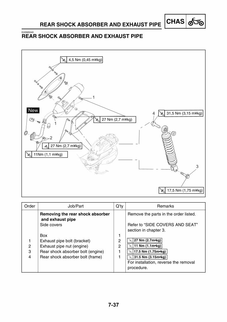
CHAS
7-37
REAR SHOCK ABSORBER AND EXHAUST PIPEEASM0049
REAR SHOCK ABSORBER AND EXHAUST PIPE
Removing the rear shock absorber Remove the parts in the order listed. and exhaust pipeSide covers Refer to “SIDE COVERS AND SEAT”
section in chapter 3.Box 1
1 Exhaust pipe bolt (bracket) 22 Exhaust pipe nut (engine) 23 Rear shock absorber bolt (engine) 14 Rear shock absorber bolt (frame) 1
For installation, reverse the removalprocedure.
Order Job/Part Q’ty Remarks
T.R 27 Nm (2.7m•kg)
17.5 Nm (1.75m•kg)T.R
T.R 31.5 Nm (3.15m•kg)
T.R 11 Nm (1.1m•kg)
T.R31,5 Nm (3,15 m¥kg)
T.R17,5 Nm (1,75 m¥kg)
T.R4,5 Nm (0,45 m¥kg)
T.R27 Nm (2,7 m¥kg)
T.R27 Nm (2,7 m¥kg)
T.R11Nm (1,1 m¥kg)
3
1
1
2
4

CHAS
7-38
REAR SHOCK ABSORBER AND EXHAUST PIPE
EAS00695
CHECKING THE REAR SHOCK ABSORBERASSEMBLY1. Check:
• rear shock absorber rodBends/damage → Replace the rear shockabsorber assembly.
• rear shock absorberOil leaks → Replace the rear shock absorberassembly.
• springDamage/wear → Replace the rear shockabsorber assembly.
• bushingsDamage/wear → Replace.
• dust sealsDamage/wear → Replace.
• boltsBends/damage/wear → Replace.

8ELEC

CHAPTER 8.ELECTRICAL
ELECTRICAL COMPONENTS ......................................................................8-1
SWITCHES ....................................................................................................8-2CHECKING SWITCH CONTINUITY ........................................................8-2
CHECKING THE SWITCHES ........................................................................8-3
CHECKING THE BULBS AND BULB SOCKETS ........................................8-4TYPES OF BULBS...................................................................................8-4CHECKING THE CONDITION OF THE BULBS ......................................8-4CHECKING THE CONDITION OF THE BULB SOCKETS ......................8-6
IGNITION SYSTEM .......................................................................................8-7CIRCUIT DIAGRAM .................................................................................8-7TROUBLESHOOTING .............................................................................8-8
ELECTRIC STARTING SYSTEM ................................................................8-11CIRCUIT DIAGRAM ...............................................................................8-11TROUBLESHOOTING ...........................................................................8-12
STARTER MOTOR ......................................................................................8-14CHECKING THE STARTER MOTOR ....................................................8-16ASSEMBLING THE STARTER MOTOR ...............................................8-17
CHARGING SYSTEM ..................................................................................8-19CIRCUIT DIAGRAM ...............................................................................8-19TROUBLESHOOTING ...........................................................................8-20
LIGHTING SYSTEM ....................................................................................8-22CIRCUIT DIAGRAM ...............................................................................8-22TROUBLESHOOTING ...........................................................................8-23CHECKING THE LIGHTING SYSTEM ..................................................8-24
SIGNALING SYSTEM .................................................................................8-27CIRCUIT DIAGRAM ...............................................................................8-27TROUBLESHOOTING ...........................................................................8-29CHECKING THE SIGNALING SYSTEM ................................................8-30
COOLING SYSTEM .....................................................................................8-36CIRCUIT DIAGRAM ...............................................................................8-36TROUBLESHOOTING ...........................................................................8-37
CARBURETOR HEATING SYSTEM ...........................................................8-40CIRCUIT DIAGRAM ...............................................................................8-40TROUBLESHOOTING ...........................................................................8-41
ELEC

ELEC
8-1
ELECTRICAL COMPONENTS
ELECTRICAL COMPONENTS
Wire harness Battery Ignition unit (CDI) Main switch Ignition coil Spark plug cap Rectifier/Regulator Fuel sender Starter relay
Starter motor Thermo switch Flasher relay Horn Fuses Relays Coolant thermo switch Carburator heater thermo switch
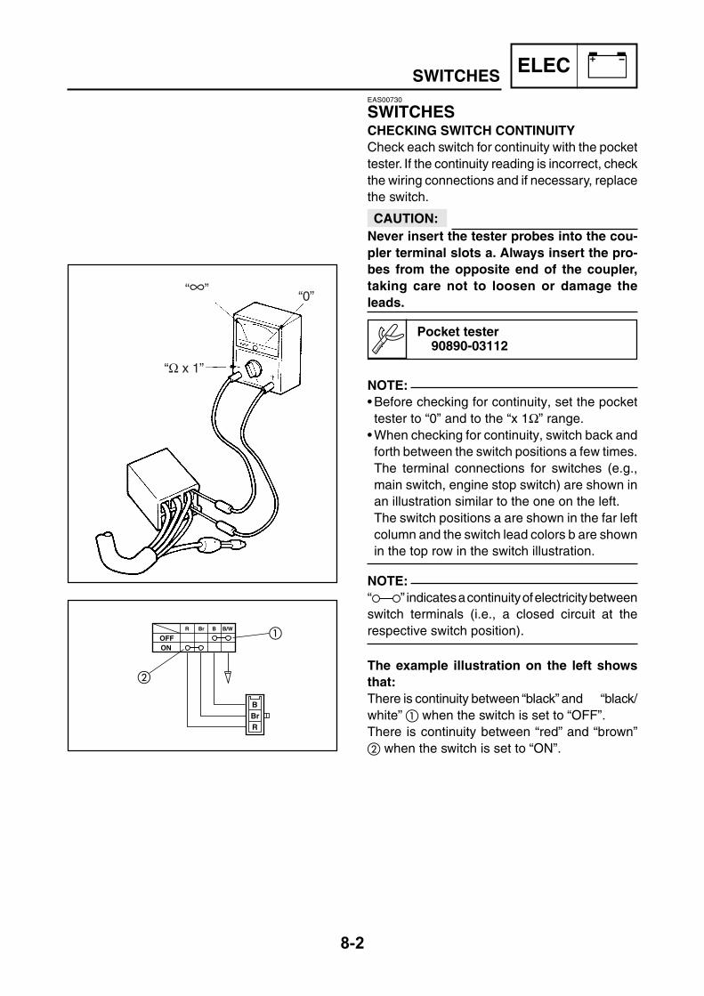
ELEC
8-2
SWITCHESEAS00730
SWITCHESCHECKING SWITCH CONTINUITYCheck each switch for continuity with the pockettester. If the continuity reading is incorrect, checkthe wiring connections and if necessary, replacethe switch.
CAUTION:Never insert the tester probes into the cou-pler terminal slots a. Always insert the pro-bes from the opposite end of the coupler,taking care not to loosen or damage theleads.
Pocket tester90890-03112
NOTE:• Before checking for continuity, set the pockettester to “0” and to the “x 1Ω” range.
• When checking for continuity, switch back andforth between the switch positions a few times.The terminal connections for switches (e.g.,main switch, engine stop switch) are shown inan illustration similar to the one on the left.The switch positions a are shown in the far leftcolumn and the switch lead colors b are shownin the top row in the switch illustration.
NOTE:“ ” indicates a continuity of electricity betweenswitch terminals (i.e., a closed circuit at therespective switch position).
The example illustration on the left showsthat:There is continuity between “black” and “black/white” when the switch is set to “OFF”.There is continuity between “red” and “brown” when the switch is set to “ON”.
“Ω x 1”
“∞”“0”
BBrR
OFFON
R Br B B/W

ELEC
8-3
CHECKING THE SWITCHESEAS00731
CHECKING THE SWITCHESCheck each switch for damage or wear, proper connections, and also for continuity between theterminals. Refer to “CHECKING SWITCH CONTINUITY” section.Damage/wear → Repair or replace.Improperly connected → Properly connect.Incorrect continuity reading → Replace the switch. Horn switch Dimmer switch Turn signal switch Main switch Front brake light switch
Light switch Start switch Fuses Rear brake light switch
B
Br BR BW
CHECK
GR
OPENOFF
ONBr
GyR
R
LOCK
GY
Br
GY
Br
B
B
B
LY
B(BLUE) (BLUE)
LY
(OPTION)
B
B
(BLUE)B
B
Ch
PG
BrWBY Dg
LB
RNL
Ch
LO
HIPUSH
OFF GY LBBrW Dg
ONGY
L
Br
LB
POS
OFF
START
OFF
L LBBrBrGY
Indicates coupler position
(option)

ELEC
8-4
CHECKING THE BULBS AND BULB SOCKETS
TYPES OF BULBSThe bulbs used on this scooter are shown in theillustration on the left.• Bulbs A and B are used for the headlights and
usually use a bulb holder which must bedetached before removing the bulb. Themajority of these types of bulbs can be removedfrom their respective socket by turning themcounterclockwise.
• Bulb C is used for turn signal and tail/brakelights and can be removed from the socket bypushing and turning the bulb counterclockwise.
• Bulbs D and E are used for meter and indi-cator lights and can be removed from theirrespective socket by pushing and turning thebulb conterclockwise for D and carefullypulling them out for E .
EAS00733
CHECKING THE BULBS ANDBULB SOCKETSCheck each bulb and bulb socket for damage orwear, proper connections, and also for continuitybetween the terminals.Damage/wear → Repair or replace the bulb, bulbsocket or both.Improperly connected → Properly connect.No continuity → Repair or replace the bulb, bulbsocket or both.
A B
CD E
CHECKING THE CONDITION OF THEBULBSThe following procedure applies to all of thebulbs.1. Remove:
• bulb

ELEC
8-5
CHECKING THE BULBS AND BULB SOCKETS
WARNING Since the headlight bulb gets extremely hot,keep flammable products and your handsaway from the bulb until it has cooled down.
CAUTION:• Be sure to hold the socket firmly when
removing the bulb. Never pull the lead,otherwise it may be pulled out of theterminal in the coupler.
• Avoid touching the glass part of theheadlight bulb to keep it free from oil,otherwise the transparency of the glass,the life of the bulb, and the luminous fluxwill be adversely affected. If the headlightbulb gets soiled, thoroughly clean it witha cloth moistened with alcohol or lacquerthinner.
2. Check:• bulb (for continuity)(with the pocket tester)No continuity → Replace.
Pocket tester90890-03112
NOTE:Before checking for continuity, set the pockettester to “0” and to the “x 1 Ω” range.
a. Connect the positive tester probe to terminal and the negative tester probe to terminal, and check the continuity.
b. Connect the positive tester probe to terminal and the negative tester probe to terminal, and check the continuity.
c. If either of the readings indicate no continuity,replace the bulb.

ELEC
8-6
CHECKING THE CONDITION OF THE BULBSOCKETSThe following procedure applies to all of the bulbsockets.1. Check:
bulb socket (for continuity)(with the pocket tester)No continuity → Replace.
Pocket tester90890-03112
NOTE:Check each bulb socket for continuity in thesame manner as described in the bulb section;however, note the following.
a. Install a good bulb into the bulb socket.b. Connect the pocket tester probes to the res-
pective leads of the bulb socket.c. Check the bulb socket for continuity. If any of
the readings indicate no continuity, replacethe bulb socket.
CHECKING THE BULBS AND BULB SOCKETS

ELEC
8-7
EAS00734
IGNITION SYSTEMCIRCUIT DIAGRAM
CDI magneto CDI unit Ignition coil Spark plug Main switch Fuse (main) Battery Front brake stop switch Rear brake stop switch21 Relay
IGNITION SYSTEM
23
13
A
B21
5
G
21
32
25
PN K O L MR
27
26
29
19 20
16H
28
12
2217
8
F
18
11
30
10
6
79
35J
24
3
4
31
C DE
F
33
34
14 15
G
B
LW
LW
(NATURAL)
RW
BB
L
L
P
CLO
CK
OD
OM
ET
ER
LW
P
B R - W W
Y
LW
LGY
ON
Br BR BW
HANDLE SWITCH 2
HANDLESWITCH 1
LGW BRGW
WL
BR
W
Br Br
B
WR
CHECK
GR
Br OrBr
YB
Or
B YB
B
B
Br
Gy
OPENOFF
ONRBr
GyR
BW
Br
Br
R
Gy
L
R
LOCK
L
B
R
L
B
Or
YRR
L
Br
Gy
NO-CONNECTION
Y
GR
Ch
PG
BrWBY
DgLB Ch BrW
Dg
P
B
GY
LY
LB
-BW L
BW
L
GYY
GY
L
Br
LB
L
Br
L
GY
LB
L
Dg
Br
LR
B
B
B
B
B
Or
WL
WR
GW
B Y G
BR
(BLACK)
(BLACK)
Dg
Ch
Ch
LW
LW
LW
LW
Dg
Ch
Br Br
G
Ch Ch
LW
R
B
LW
LW
Dg
BR
NO-CONNECTIONBr
Ch
GW
WR
WL
NO-CONNECTION
B
NO-CONNECTION
(RED)
NO-CONNECTION
B
NO-CONNECTION
METERASSY.
Br
R
ANTI-THEFT
ALARM
(OPTION)
B
Dg
LW
LW
L
R
L
Br
RW
W
HEAD LIGHT ASSY.
Sb
Dg
BNO-CONNECTION
LW
LW
(RED)
L
Ch
G
B
Dg
Y
LW
L
Ch
G
B
Dg
Y
B
L
Y
Br
Y
GY
GY
Br
Br
YBYB
Br
L
LL
Y
Ch
G
DgCh
BWB
LW
B
Dg
Ch
ILLU
MI
Y
R
WIRE LEAD surANTI-THEFT 1 et 4
WIRE LEAD sur SIDE STAND
B
B
RW
TH
ER
MO
. MO
TO
R
TU
RN
L
TU
RN
R
HI B
EA
M
ILLU
MI
FU
EL
ME
TE
R
Br B
r
BrW
Br
W
BW
W W
W
W W
W (1)
Dg
(4)
Y
G
GR
W
W
W
Y
B
Br
Br
RNL
BrW
LW
Ch
LB
P
LO
HIPUSH
OFF
RW
LBBrGY
POS
OFF
START
OFF
LW
R
B
R
R
R
B
LW
BRW
LW
R
Y
B
Dg
GR
Dg
YR
LY
YR
BB
B
B
Ch
B
B
Or
WRWL
L
Y
LY
LYLY
LYLY
LY
LY
LY
LY
GY LBBrW
LY
Y G
BR
Br
L LB
B
Br
B
B
P
Dg
For LW/LWand LY/LY
BrGY
R
Sb
Sb
B
L
B
LY
B
B
LY
B(BLUE) (BLUE)
LY
LW
(OPTION)
BB
B
B
(BLUE)B
B
Ch
B

ELEC
8-8
EAS00736
TROUBLESHOOTING
THE IGNITION SYSTEM FAILS TOOPERATE (NO SPARK ORINTERMITTENT SPARK).
Check:1. Main fuse2. Battery3. Spark plug4. Ignition spark gap5. Spark plug cap resistance6. Ignition coil resistance7. Main switch8. Pickup coil resistance9. Wiring (of the entire ignition system)
NOTE:• Before troubleshooting, remove the followingpart(s):
1) Side covers2) Footrest board3) Seat and box• Troubleshoot with the following special tool(s).
Ignition checker90890-06754
Pocket tester90890-03112
EAS00738
1.Main fuse
• Check the main fuse for continuity.• Refer to “CHECKING THE FUSES” in chapter3.
• Is the main fuse OK?
Replace the fuse.
• Clean the batteryterminals.
• Recharge or re-place the battery.
YES NO
EAS00739
2.Battery
• Check the condition of the battery.Refer to “CHECKING THE BATTERY” inchapter 3.
Minimum open-circuit voltage12.8 V or more at 20°C
• Is the battery OK?
YES NO
EAS00740
3.Spark plug
• Check the condition of the spark plug.• Check the spark plug type.• Measure the spark plug gap.Refer to “CHECKING THE SPARK PLUG” inchapter 3.
Standard spark plugCR8E (NGK)
Spark plug gap0.5 ~ 0.7 mm
•Is the spark plug in good condition, is it of thecorrect type, and is its gap within specifica-tion?
Re-gap or replace thespark plug.
YES NO
IGNITION SYSTEM

ELEC
8-9
IGNITION SYSTEMEAS00742
4.Ignition spark gap
• Disconnect the spark plug cap from the sparkplug.
• Connect the ignition checker/dynamic sparktester as shown.
• Spark plug cap• Set the main switch to “ON”.• Measure the ignition spark gap a .• Crank the engine by pushing the starterswitch and gradually increase the spark gapuntil a misfire occurs.
Minimum ignition spark gap6 mm
• Is there a spark and is the spark gap withinspecification?
The ignition system isOK.
EAS00744
5.Spark plug cap resistance
• Remove the spark plug cap from the sparkplug lead.
• Connect the pocket tester (“Ω X 1k” range)to the spark plug cap.
• Measure the spark plug cap resistance.
Spark plug cap resistance10 x kΩ at 20°C
• Is the spark plug cap OK?
Replace the sparkplug cap.
EAS00746
6. Ignition coil resistance
• Disconnect the ignition coil connectors fromthe ignition coil terminals.
• Connect the pocket tester (Ω X 1) to theignition coil as shown.
• Measure primary coil resistance.
Positive tester probe →→→→→ blackNegative tester probe →→→→→ orange
• Measure the primary coil resistance.
Primary coil resistance0.32 ~ 0.48 Ω at 20°C
• Connect the pocket tester (Ω X 1k) to theignition coil as shown.
• Measure the secondary coil resistance.
Negative tester probe →→→→→ blackPositive tester probe →→→→→ spark plug lead
• Measure the secondary coil resistance.
Secondary coil resistance5.7 ~ 8.5 kΩ at 20°C
• Is the ignition coil OK?
Replace the ignitioncoil.
YES NO
YES NO
a
‰ x 1
‰ x 1k
YESNO

ELEC
8-10
9. Source coil resistance
• Disconnect the source coil coupler from thewire harness.
• Connect the pocket tester (Ω X 100) to thecharging coil terminal as shown.
Positive tester probe →→→→→ green/white Negative tester probe →→→→→ black/red
• Measure the source coil resistance.
Source coil resistance720 ~ 1080 Ω at 20°C(between brown/black andgreen/white)
• Is the source coil OK?
IGNITION SYSTEMEAS00749
7.Main switch
• Check the main switch for continuity.Refer to “CHECKING THE SWITCHES”.
• Is the main switch OK?
EAS00748
8.Pickup coil resistance
• Disconnect the pickup coil coupler from thewire harness.
• Connect the pocket tester (Ω X 100) to thepickup coil terminal as shown.
Positive tester probe →→→→→ red/black Negative tester probe →→→→→ green/white
• Measure the pickup coil resistance.
Pickup coil resistance248 ~ 372 Ω at 20°C(between white/red and white/green)
• Is the pickup coil OK?
EAS00754
10. Wiring
• Check the entire ignition system’s wiring.Refer to “CIRCUIT DIAGRAM”.
• Is the ignition system’s wiring properly con-nected and without defects?
Replace the ignitionunit. (CDI unit)
Replace the stator. Properly connect orrepair the ignition sys-tem’s wiring.
YES NO
YES NO
Replace the mainswitch.
YESNO
GW
WL
BR
WR
BR
GW
WR
WL
GW
BRWR
WL
YES NO
Replace the stator.

ELEC
8-11
EAS00755
ELECTRIC STARTING SYSTEMCIRCUIT DIAGRAM
Main switch Fuse (main) Battery Starter relay Starter motor A Starter switch Front brake stop switch Rear brake stop switch21 Relay32 Anti-theft alarm (option)
ELECTRIC STARTING SYSTEM
23
13
A
B21
5
G
21
32
25
PN K O L MR
27
26
29
19 20
16H
28
12
2217
8
F
18
11
30
10
6
79
35J
24
3
4
31
C DE
F
33
34
14 15
G
B
LW
LW
(NATURAL)
RW
BB
L
L
P
CLO
CK
OD
OM
ET
ER
LW
P
B R - W W
Y
LW
LGY
ON
Br BR BW
HANDLE SWITCH 2
HANDLESWITCH 1
LGW BRGW
WL
BR
W
Br Br
B
WR
CHECK
GR
Br OrBr
YB
Or
B YB
B
B
Br
Gy
OPENOFF
ONRBr
GyR
BW
Br
Br
R
Gy
L
R
LOCK
L
B
R
L
B
Or
YRR
L
Br
Gy
NO-CONNECTION
Y
GR
Ch
PG
BrWBY
DgLB Ch BrW
Dg
P
B
GY
LY
LB
-BW L
BW
L
GYY
GY
L
Br
LB
L
Br
L
GY
LB
L
Dg
Br
LR
B
B
B
B
B
Or
WL
WR
GW
B Y G
BR
(BLACK)
(BLACK)
Dg
Ch
Ch
LW
LW
LW
LW
Dg
Ch
Br Br
G
Ch Ch
LW
R
B
LW
LW
Dg
BR
NO-CONNECTIONBr
Ch
GW
WR
WL
NO-CONNECTION
B
NO-CONNECTION
(RED)
NO-CONNECTION
B
NO-CONNECTION
METERASSY.
Br
R
ANTI-THEFT
ALARM
(OPTION)
B
Dg
LW
LW
L
R
L
Br
RW
W
HEAD LIGHT ASSY.
Sb
Dg
BNO-CONNECTION
LW
LW
(RED)
L
Ch
G
B
Dg
Y
LW
L
Ch
G
B
Dg
Y
B
L
Y
Br
Y
GY
GY
Br
Br
YBYB
Br
L
LL
Y
Ch
G
DgCh
BWB
LW
B
Dg
Ch
ILLU
MI
Y
R
WIRE LEAD surANTI-THEFT 1 et 4
WIRE LEAD sur SIDE STAND
B
B
RW
TH
ER
MO
. MO
TO
R
TU
RN
L
TU
RN
R
HI B
EA
M
ILLU
MI
FU
EL
ME
TE
R
Br B
r
BrW
Br
W
BW
W W
W
W W
W (1)
Dg
(4)
Y
G
GR
W
W
W
Y
B
Br
Br
RNL
BrW
LW
Ch
LB
P
LO
HIPUSH
OFF
RW
LBBrGY
POS
OFF
START
OFF
LW
R
B
R
R
R
B
LW
BRW
LW
R
Y
B
Dg
GR
Dg
YR
LY
YR
BB
B
B
Ch
B
B
Or
WRWL
L
Y
LY
LYLY
LYLY
LY
LY
LY
LY
GY LBBrW
LY
Y G
BR
Br
L LB
B
Br
B
B
P
Dg
For LW/LWand LY/LY
BrGY
R
Sb
Sb
B
L
B
LY
B
B
LY
B(BLUE) (BLUE)
LY
LW
(OPTION)
BB
B
B
(BLUE)B
B
Ch
B

ELEC
8-12
EAS00739
2.Battery
• Check the condition of the battery.Refer to “CHECKING THE BATTERY” inchapter 3.
Minimum open-circuit voltage12.8 V or more at 20°C
• Is the battery OK?
EAS00757
TROUBLESHOOTING
THE STARTER MOTOR FAILS TO TURN.
Check:1. main fuse2. battery3. starter motor4. starter relay5. main switch6. front/rear brake switch7. starter switch8. wiring (entire starting system)
NOTE:Before troubleshooting, remove the followingpart(-s)1) Side covers2) Box and seatTroubleshoot with the following special tool(-s).
Pocket tester90890-03112
EAS00738
1.Main fuse
• Check the main fuse for continuity.• Refer to “CHECKING THE FUSES” in chapter3.
• Is the main fuse OK?
Replace the fuse.
• Clean the batteryterminals.
• Recharge or replacethe battery.
YES NO
YES NO
EAS00758
3.Starter motor
• Connect the positive battery terminal andstarter motor lead with a jumper lead .
WARNING • A wire that is used as a jumper lead musthave at least the same capacity or moreas that of the battery lead, otherwise thejumper lead may burn.
• This check is likely to produce sparks,therefore make sure nothing flammableis in the vicinity.
• Does the starter motor turn?
Repair or replace thestarter motor.
YES NO
ELECTRIC STARTING SYSTEM
+ -

ELEC
8-13
EAS00761
4.Starter relay
• Disconnect the starter relay coupler from thecoupler.
• Connect the pocket tester (Ω X 1) and battery(12 V) to the starter relay coupler as shown.
Positive battery terminal →→→→→ red/white Negative battery terminal →→→→→ blue/white
Positive tester probe →→→→→ red Negative tester probe →→→→→ red
• Does the starter relay have continuity be-tween red and black when it clicks?
EASM0050
6.Front and Rear brake switch
• Check the front and rear switches for conti-nuity.Refer to “CHECKING THE SWITCHES”.
• Is the front and rear switches OK?
EAS00764
7.Starter switch
• Check the starter switch for continuity.Refer to “CHECKING THE SWITCHES”.
• Is the starter switch OK?
EAS00766
8.Wiring
• Check the entire starting system’s wiring.Refer to “CIRCUIT DIAGRAM”.
• Is the starting system’s wiring properly con-nected and without defects?
Replace the starterrelay.
Replace the front orrear brake switch.
The starting systemcircuit is OK.
YES NO
EAS00749
5.Main switch
• Check the main switch for continuity.Refer to “CHECKING THE SWITCHES”.
• Is the main switch OK?
YES NO
Replace the mainswitch.
YES NO
Replace the right han-dlebar switch.
YES NO
Properly connect orrepair the starting sys-tem’s wiring.
YESNO
ELECTRIC STARTING SYSTEM
R
R
LW LW
BRW

ELEC
8-14
EASM0051
STARTER MOTOR
Removing the starter motor Remove/disassemble the parts inthe order listed.
Side covers Refer to “SIDE COVERS AND SEAT”Box and seat section in chapter 3.
1 Starter connector and coupler 1/12 Starter motor fixing bolts/washer 2/23 Starter motor 1
Disassembling the starter motor Starter motor mounting bolts 2 Washers/o-rings 2/2 Starter motor rear cover 1 O-ring 1 Stator assembly 1 Armature assembly 1
STARTER MOTOR
Order Job/Part Q’ty Remarks
1
2
3
T.R65 Nm (6.5 m.kg)
T.R5 Nm (0.5 m.kg)

ELEC
8-15
Brushes/Springs 2/2 Brush holder/washer 1/1 O-ring 1 Starter motor front cover/O-ring 1/1
For installation/assembly, reverse theremoval/disassembly procedure.
STARTER MOTOR
Order Job/Part Q’ty Remarks
1
2
3
T.R65 Nm (6.5 m.kg)
T.R5 Nm (0.5 m.kg)

ELEC
8-16
4. Measure:• armature assembly resistances (commutatorand insulation)Out of specification → Replace the startermotor.
a. Measure the armature assembly resistanceswith the pocket tester.
Pocket tester90890-03112
Armature coilCommutator resistance 0.0306 ~ 0.0374 Ω at 20°C
Insulation resistance Above 1 MΩ at 20°C
b. If any resistance is out of specification, re-place the starter motor.
EAS00770
CHECKING THE STARTER MOTOR1. Check:
• commutatorDirt → Clean with 600 grit sandpaper.
2. Measure:• commutator diameter aOut of specification → Replace the startermotor.
Commutator diameter22 mm<Limit>: 21 mm
3. Measure:• mica undercut aOut of specification → Scrape the mica to theproper measurement with a hacksaw bladewhich has been ground to fit the commutator.
Mica undercut1.5 mm
NOTE:The mica of the commutator must be undercutto ensure proper operation of the commutator.
STARTER MOTOR
a
a

ELEC
8-17
5. Measure:• brush length a .Out of specification → Replace the brushesas a set.
Brush length10 mm<Limit>: 3.5 mm
EAS00772
ASSEMBLING THE STARTER MOTOR1. Install:
• Washer• Brush• Brush seat
NOTE:Align the tab on the brush seat with the slot in thestarter motor rear cover.
2. Install:• Armature assembly• Stator assembly• starter motor front cover• starter motor rear cover
NOTE:Align the match marks a on the starter motoryoke with the match marks b on the front andstarter motor rear covers.
6. Measure:• brush spring forceOut of specification → Replace the brushsprings as a set.
Brush spring force5.6 ~ 8.3 N
7. Check:• gear teethDamage/wear → Replace the gear.
8. Check:• bearing• oil sealDamage/wear → Replace the defective part(-s).
STARTER MOTOR
a b
a

ELEC
8-18
3. Install:• O-rings • washers• starter motor mounting bolts• stater motor fixing bolts
STARTER MOTOR
T.R 5 Nm (0.5m•kg)
T.R 65 Nm (6.5m•kg)

ELEC
8-19
EAS00773
CHARGING SYSTEMCIRCUIT DIAGRAM
CDI magneto Fuse (main) Battery Rectifier/regulator
CHARGING SYSTEM
23
13
A
B21
5
G
21
32
25
PN K O L MR
27
26
29
19 20
16H
28
12
2217
8
F
18
11
30
10
6
79
35J
24
3
4
31
C DE
F
33
34
14 15
G
B
LW
LW
(NATURAL)
RW
BB
L
L
P
CLO
CK
OD
OM
ET
ER
LW
P
B R - W W
Y
LW
LGY
ON
Br BR BW
HANDLE SWITCH 2
HANDLESWITCH 1
LGW BRGW
WL
BR
W
Br Br
B
WR
CHECK
GR
Br OrBr
YB
Or
B YB
B
B
Br
Gy
OPENOFF
ONRBr
GyR
BW
Br
Br
R
Gy
L
R
LOCK
L
B
R
L
B
Or
YRR
L
Br
Gy
NO-CONNECTION
Y
GR
Ch
PG
BrWBY
DgLB Ch BrW
Dg
P
B
GY
LY
LB
-BW L
BW
L
GYY
GY
L
Br
LB
L
Br
L
GY
LB
L
Dg
Br
LR
B
B
B
B
B
Or
WL
WR
GW
B Y G
BR
(BLACK)
(BLACK)
Dg
Ch
Ch
LW
LW
LW
LW
Dg
Ch
Br Br
G
Ch Ch
LW
R
B
LW
LW
Dg
BR
NO-CONNECTIONBr
Ch
GW
WR
WL
NO-CONNECTION
B
NO-CONNECTION
(RED)
NO-CONNECTION
B
NO-CONNECTION
METERASSY.
Br
R
ANTI-THEFT
ALARM
(OPTION)
B
Dg
LW
LW
L
R
L
Br
RW
W
HEAD LIGHT ASSY.
Sb
Dg
BNO-CONNECTION
LW
LW
(RED)
L
Ch
G
B
Dg
Y
LW
L
Ch
G
B
Dg
Y
B
L
Y
Br
Y
GY
GY
Br
Br
YBYB
Br
L
LL
Y
Ch
G
DgCh
BWB
LW
B
Dg
Ch
ILLU
MI
Y
R
WIRE LEAD surANTI-THEFT 1 et 4
WIRE LEAD sur SIDE STAND
B
B
RW
TH
ER
MO
. MO
TOR
TU
RN
L
TU
RN
R
HI B
EA
M
ILLU
MI
FU
EL
ME
TE
R
Br B
r
BrW
Br
W
BW
W W
W
W W
W (1)
Dg
(4)
Y
G
GR
W
W
W
Y
B
Br
Br
RNL
BrW
LW
Ch
LB
P
LO
HIPUSH
OFF
RW
LBBrGY
POS
OFF
START
OFF
LW
R
B
R
R
R
B
LW
BRW
LW
R
Y
B
Dg
GR
Dg
YR
LY
YR
BB
B
B
Ch
B
B
Or
WRWL
L
Y
LY
LYLY
LYLY
LY
LY
LY
LY
GY LBBrW
LY
Y G
BR
Br
L LB
B
Br
B
B
P
Dg
For LW/LWand LY/LY
BrGY
R
Sb
Sb
B
L
B
LY
B
B
LY
B(BLUE) (BLUE)
LY
LW
(OPTION)
BB
B
B
(BLUE)B
B
Ch
B

ELEC
8-20
EAS00738
1.Main fuse
• Check the main fuse for continuity.• Refer to “CHECKING THE FUSES” in chapter3.
• Is the main fuse OK?
Replace the fuse.
EAS00774
TROUBLESHOOTING
THE BATTERY IS NOT BEING CHARGED.
Check:1. main fuse2. battery3. charging voltage4. stator coil resistance5. wiring (of the entire charging system)
NOTE:Before troubleshooting, remove the followingpart(s):1) Side covers2) Box and seatTroubleshoot with the following special tool(s).
Engine tachometer90890-03113
Pocket tester90890-03112
YES NO
• Clean the batteryterminals.
• Recharge or re-place the battery.
EAS00739
2.Battery
• Check the condition of the battery.Refer to “CHECKING THE BATTERY” inchapter 3.
Minimum open-circuit voltage12.8 V or more at 20°C
• Is the battery OK?
YES NO
EAS00775
3.Charging voltage
• Connect the engine tachometer to the sparkplug lead of the cylinder.
• Connect the pocket tester (DC V 20) to thebattery as shown.
Positive tester probe →→→→→ positive batteryterminal
Negative tester probe →→→→→negative batteryterminal
• Start the engine and let it run at approxi-mately 5,000 r/min.
• Measure the charging voltage.
Charging voltagemeasured voltage - terminal14 V at 5,000 r/min
CHARGING SYSTEM
- +

ELEC
8-21
EAS00776
4.Stator coil resistance
• Disconnect the stator coil coupler from thewire harness.
• Connect the pocket tester (Ω x 1) to the statorcoils assembly coupler as shown.
Positive tester probe →→→→→ white Negative tester probe →→→→→ white
Positive tester probe →→→→→ white Negative tester probe →→→→→ white
• Measure the stator coil resistances.
Stator coil resistance0.6 ~ 0.9 Ω at 20°C
• Is the stator coil OK?
EAS00779
5.Wiring connections
• Check the wiring connections of the entirecharging system.Refer to “CIRCUIT DIAGRAM”.
• Is the charging system’s wiring properly con-nected and without defects?
Replace the stator coilassembly.
Properly connect orrepair the chargingsystem’s wiring.
Replace the rectifier/regulator.
NOTE:Make sure the battery is fully charged.
• Is the charging voltage within specification?
YESNO
The charging circuitis OK.
YES NO
YESNO
CHARGING SYSTEM
1 2
3
W W
W

ELEC
8-22
LIGHTING SYSTEMEAS00780
LIGHTING SYSTEMCIRCUIT DIAGRAM
Main switch Fuse (main) Battery B Light switch E Flasher switch F Headlight Tail/stop light22 K Meter light
23
13
A
B21
5
G
21
32
25
PN K O L MR
27
26
29
19 20
16H
28
12
2217
8
F
18
11
30
10
6
79
35J
24
3
4
31
C DE
F
33
34
14 15
G
B
LW
LW
(NATURAL)
RW
BB
L
L
P
CLO
CK
OD
OM
ET
ER
LW
P
B R - W W
Y
LW
LGY
ON
Br BR BW
HANDLE SWITCH 2
HANDLESWITCH 1
LGW BRGW
WL
BR
W
Br Br
B
WR
CHECK
GR
Br OrBr
YB
Or
B YB
B
B
Br
Gy
OPENOFF
ONRBr
GyR
BW
Br
Br
R
Gy
L
R
LOCK
L
B
R
L
B
Or
YRR
L
Br
Gy
NO-CONNECTION
Y
GR
Ch
PG
BrWBY
DgLB Ch BrW
Dg
P
B
GY
LY
LB
-BW L
BW
L
GYY
GY
L
Br
LB
L
Br
L
GY
LB
L
Dg
Br
LR
B
B
B
B
B
Or
WL
WR
GW
B Y G
BR
(BLACK)
(BLACK)
Dg
Ch
Ch
LW
LW
LW
LW
Dg
Ch
Br Br
G
Ch Ch
LW
R
B
LW
LW
Dg
BR
NO-CONNECTIONBr
Ch
GW
WR
WL
NO-CONNECTION
B
NO-CONNECTION
(RED)
NO-CONNECTION
B
NO-CONNECTION
METERASSY.
Br
R
ANTI-THEFT
ALARM
(OPTION)
B
Dg
LW
LW
L
R
L
Br
RW
W
HEAD LIGHT ASSY.
Sb
Dg
BNO-CONNECTION
LW
LW
(RED)
L
Ch
G
B
Dg
Y
LW
L
Ch
G
B
Dg
Y
B
L
Y
Br
Y
GY
GY
Br
Br
YBYB
Br
L
LL
Y
Ch
G
DgCh
BWB
LW
B
Dg
Ch
ILLU
MI
Y
R
WIRE LEAD surANTI-THEFT 1 et 4
WIRE LEAD sur SIDE STAND
B
B
RW
TH
ER
MO
. MO
TO
R
TU
RN
L
TU
RN
R
HI B
EA
M
ILLU
MI
FU
EL
ME
TE
R
Br B
r
BrW
Br
W
BW
W W
W
W W
W (1)
Dg
(4)
Y
G
GR
W
W
W
Y
B
Br
Br
RNL
BrW
LW
Ch
LB
P
LO
HIPUSH
OFF
RW
LBBrGY
POS
OFF
START
OFF
LW
R
B
R
R
R
B
LW
BRW
LW
R
Y
B
Dg
GR
Dg
YR
LY
YR
BB
B
B
Ch
B
B
Or
WRWL
L
Y
LY
LYLY
LYLY
LY
LY
LY
LY
GY LBBrW
LY
Y G
BR
Br
L LB
B
Br
B
B
P
Dg
For LW/LWand LY/LY
BrGY
R
Sb
Sb
B
L
B
LY
B
B
LY
B(BLUE) (BLUE)
LY
LW
(OPTION)
BB
B
B
(BLUE)B
B
Ch
B

ELEC
8-23
EAS00781
TROUBLESHOOTING
ANY OF THE FOLLOWING FAIL TOLIGHT: HEADLIGHT, HIGH BEAMINDICATOR LIGHT, TAILLIGHT,AUXILIARY LIGHT OR INSTRUMENTLIGHT .
Check:1. main fuse2. battery3. main switch4. lighting switch5. dimmer switch6. wiring (of the entire lighting system)
NOTE:Before troubleshooting, remove the followingpart(s):1)Side covers2)Box and seat3)Front cover and handlebar coversTroubleshoot with the following special tool(s).
Pocket tester90890-03112
EAS00738
1.Main fuse
• Check the main fuse for continuity.• Refer to “CHECKING THE FUSES” in chap-ter 3.
• Is the main fuse OK?
Replace the fuse.
YES NO
• Clean the batteryterminals.
• Recharge or re-place the battery.
EAS00739
2.Battery
• Check the condition of the battery.Refer to “CHECKING THE BATTERY” inchapter 3.
Minimum open-circuit voltage12.8 V or more at 20°C
• Is the battery OK?
YES NO
EAS00749
3.Main switch
• Check the main switch for continuity.Refer to “CHECKING THE SWITCHES”.
• Is the main switch OK?
YES NO
Replace the mainswitch.
EAS00783
4.Lighting switch
• Check the lighting switch for continuity.Refer to “CHECKING THE SWITCHES”.
• Is the lighting switch OK?
YES NO
The lighting switch isfaulty. Replace theright handlebarswitch.
LIGHTING SYSTEM

ELEC
8-24
LIGHTING SYSTEMEAS00784
5.Hi/Lo beam switch
• Check the Hi/Lo beam switch for continuity.Refer to “CHECKING THE SWITCHES”.
• Is the Hi/Lo beam switch OK?
EAS00787
6.Wiring (of the entire lighting system)
• Check the entire lighting system’s wiring.Refer to “CIRCUIT DIAGRAM”.
• Is the lighting system’s wiring properly con-nected and without defects?
EAS00788
CHECKING THE LIGHTING SYSTEM1. The headlight and the high beam indicator
light fail to come on.
1.Headlight bulb and socket
• Check the headlight bulb and socket forcontinuity.
• Are the headlight bulb and socket OK?
YES NO
The Hi/Lo beamswitch is faulty.Replace the lefthandlebar switch.
YESNO
Check the conditionof each of the lightingsystem’s circuits.Refer to “CHECKINGTHE LIGHTINGSYSTEM”.
Properly connect orrepair the lightingsystem’s wiring.
YES NO
2.Voltage
• Connect the pocket tester (DC V 20) to theheadlight and high beam indicator light cou-plers as shown.
A When the dimmer switch is set to “ ”B When the dimmer switch is set to “ ”
• Headlight coupler (wire harness side)
HeadlightPositive tester probe →
yellow or green Negative tester probe →
black High beam indicator light
Positive tester probe → yellow Negative tester probe → black
Replace the headlightbulb, socket or both.
L
Br
BrG
YDg
Ch
B
L
Ch
G
B
Dg
Y
Y G
B
A B

ELEC
8-25
• Meter light coupler (wire harness side)• Set the main switch to “ON”.• Set the light switch to “ ”.• Set the dimmer switch to “ ” or “ ”.• Measure the voltage (12 V) of green on theheadlight coupler (wire harness side).
• Is the voltage within specification?
EAS00789
2. The meter light fails to come on.
1.Meter light bulb and socket
• Check the meter light bulb and socket forcontinuity.
• Are the meter light bulb and socket OK?
YESNO
This circuit is OK.The wiring circuit fromthe main switch to theheadlight coupler isfaulty and must berepaired.
2.Voltage
• Connect the pocket tester (20 V) to the meterlight coupler (wire harness side) as shown.
Positive tester probe → blue Negative tester probe → black
• Set the main switch to “ON”.• Set the light switch to “ ” or “ ”.• Measure the voltage (12 V) of blue on themeter light coupler (wire harness side).
• Is the voltage within specification?
YES NO
Replace the meterlight bulb, socket orboth.
YESNO
This circuit is OK.The wiring circuit fromthe main switch to themeter light coupler isfaulty and must berepaired.
LIGHTING SYSTEM
L
P
B
L
Br
YDg Ch
G
METERASSY.
SbGR
YDg
Ch
BR
Br

ELEC
8-26
EAS00790
3. The tail/brake light fails to come on.
1.Tail/brake light bulb and socket
• Check the tail/brake light bulb and socket forcontinuity.
• Are the tail/brake light bulb and socket OK?
YES NO
Replace the tail/brakelight bulb, socket orboth.
LIGHTING SYSTEM
2.Voltage
• Connect the pocket tester (DC V 20) to thetail/brake light coupler (wire harness side) asshown.
Positive tester probe → blue Negative tester probe → black
• Set the main switch to “ON”.• Set the light switch to “ ” or “ ”.• Measure the voltage (12 V) of blue on thetail/brake light coupler (tail/brake light side).
• Is the voltage within specification?
YESNO
This circuit is OK.The wiring circuit fromthe main switch to thetail/brake light coupleris faulty and must berepaired.
B
L
B
Y
EAS00791
4. The front postion light fails to come on.
1.Auxiliary light bulb and socket
• Check the auxiliary light bulb and socket forcontinuity.
Refer to "CHECKING THE BULBS ANDBULB SOCKET".• Are the auxiliary light bulb and socket OK?
YES NO
Replace the auxiliarylight bulb, socket orboth.
2.Voltage
• Connect the pocket tester (DC V 20) to theauxiliary light coupler (wire harness side) asshown.
Positive tester probe → blue Negative tester probe → black
• Set the main switch to “ON”.• Set the light switch to “ ” or “ ”.• Measure the voltage (12 V) of blue on theauxiliary light coupler (wire harness side).
• Is the voltage within specification?
YESNO
This circuit is OK.The wiring circuit fromthe main switch to theauxiliary lightconectors is faulty andmust be repaired.
L
B

ELEC
8-27
SIGNALING SYSTEMEAS00793
SIGNALING SYSTEMCIRCUIT DIAGRAM
23
13
A
B21
5
G
21
32
25
PN K O L MR
27
26
29
19 20
16H
28
1222
17
8
F
18
11
30
10
6
79
35J
24
3
4
31
C DE
F
33
34
14 15
G
B
LW
LW
(NATURAL)
RW
BB
L
L
P
CLO
CK
OD
OM
ET
ER
LW
P
B R - W W
Y
LW
LGY
ON
Br BR BW
HANDLE SWITCH 2
HANDLESWITCH 1
LGW BRGW
WL
BR
W
Br Br
B
WR
CHECK
GR
Br OrBr
YB
Or
B YB
B
B
Br
Gy
OPENOFF
ONRBr
GyR
BW
Br
Br
R
Gy
L
R
LOCK
L
B
R
L
B
Or
YRR
L
Br
Gy
NO-CONNECTION
Y
GR
Ch
PG
BrWBY
DgLB Ch BrW
Dg
P
B
GY
LY
LB
-BW L
BW
L
GYY
GY
L
Br
LB
L
Br
L
GY
LB
L
Dg
Br
LR
B
B
B
B
B
Or
WL
WR
GW
B Y G
BR
(BLACK)
(BLACK)
Dg
Ch
Ch
LW
LW
LW
LW
Dg
Ch
Br Br
G
Ch Ch
LW
R
B
LW
LW
Dg
BR
NO-CONNECTIONBr
Ch
GW
WR
WL
NO-CONNECTION
B
NO-CONNECTION
(RED)
NO-CONNECTION
B
NO-CONNECTION
METERASSY.
Br
R
ANTI-THEFT
ALARM
(OPTION)
B
Dg
LW
LW
L
R
L
Br
RW
W
HEAD LIGHT ASSY.
Sb
Dg
BNO-CONNECTION
LW
LW
(RED)
L
Ch
G
B
Dg
Y
LW
L
Ch
G
B
Dg
Y
B
L
Y
Br
Y
GY
GY
Br
Br
YBYB
Br
L
LL
Y
Ch
G
DgCh
BWB
LW
B
Dg
Ch
ILLU
MI
Y
R
WIRE LEAD surANTI-THEFT 1 et 4
WIRE LEAD sur SIDE STAND
B
B
RW
TH
ER
MO
. MO
TO
R
TU
RN
L
TU
RN
R
HI B
EA
M
ILLU
MI
FU
EL
ME
TE
R
Br B
r
BrW
Br
W
BW
W W
W
W W
W (1)
Dg
(4)
Y
G
GR
W
W
W
Y
B
Br
Br
RNL
BrW
LW
Ch
LB
P
LO
HIPUSH
OFF
RW
LBBrGY
POS
OFF
START
OFF
LW
R
B
R
R
R
B
LW
BRW
LW
R
Y
B
Dg
GR
Dg
YR
LY
YR
BB
B
B
Ch
B
B
Or
WRWL
L
Y
LY
LYLY
LYLY
LY
LY
LY
LY
GY LBBrW
LY
Y G
BR
Br
L LB
B
Br
B
B
P
Dg
For LW/LWand LY/LY
BrGY
R
Sb
Sb
B
L
B
LY
B
B
LY
B(BLUE) (BLUE)
LY
LW
(OPTION)
BB
B
B
(BLUE)B
B
Ch
B

ELEC
8-28
SIGNALING SYSTEM
Main switch Fuse (main) Battery C Horn switch
E Turn signal switch H Left front flasher
J Right front flasher Left rear flasher Right rear flasher Tail/stop light Horn Flasher relay22 P Coolant thermo indicator light
N Fuel sender indicatorR Clock and odometerL Flasher light indicatorM Flasher light indicator
23 Sender

ELEC
8-29
EAS00794
TROUBLESHOOTING
ANY OF THE FOLLOWING FAIL TOLIGHT: FLASHER LIGHT, BRAKE LIGHTOR AN INDICATOR LIGHT.THE HORN FAILS TO SOUND.
Check:1. main fuse2. battery3. main switch4. wiring (of the entire signalling system)
NOTE:• Before troubleshooting, remove the followingpart(s):
1) Side covers2) Box and seat3) Battery cover• Troubleshoot with the following special tool(s).
Pocket tester90890-03112
EAS00738
1.Main fuse
• Check the main fuse for continuity.• Refer to “CHECKING THE FUSES” in chap-ter 3.
• Is the main fuse OK?
Replace the fuse.
• Clean the batteryterminals.
• Recharge or re-place the battery.
YES NO
EAS00739
2.Battery
• Check the condition of the battery.Refer to “CHECKING THE BATTERY” inchapter 3.
Minimum open-circuit voltage12.8 V or more at 20°C
• Is the battery OK?
YES NO
EAS00749
3.Main switch
• Check the main switch for continuity.Refer to “CHECKING THE SWITCHES”.
• Is the main switch OK?
YES NO
Replace the mainswitch.
SIGNALING SYSTEM
EAS00795
4.Wiring
• Check the entire signal system’s wiring.Refer to “CIRCUIT DIAGRAM”.
• Is the signalling system’s wiring properlyconnected and without defects?
YESNO
Check the conditionof each of the signal-ling system’s circuits.Refer to “CHECKINGTHE SIGNALLINGSYSTEM”.
Properly connect orrepair the signallingsystem’s wiring.
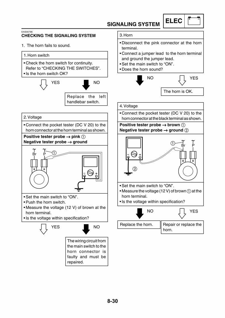
ELEC
8-30
SIGNALING SYSTEMEAS00796
CHECKING THE SIGNALING SYSTEM
1. The horn fails to sound.
1.Horn switch
• Check the horn switch for continuity.Refer to “CHECKING THE SWITCHES”.
• Is the horn switch OK?
3.Horn
• Disconnect the pink connector at the hornterminal.
• Connect a jumper lead to the horn terminaland ground the jumper lead.
• Set the main switch to “ON”.• Does the horn sound?
YES NO
2.Voltage
• Connect the pocket tester (DC V 20) to thehorn connector at the horn terminal as shown.
Positive tester probe →→→→→ pink Negative tester probe →→→→→ ground
• Set the main switch to “ON”.• Push the horn switch.• Measure the voltage (12 V) of brown at thehorn terminal.
• Is the voltage within specification?
Replace the lefthandlebar switch.
YES NO
The wiring circuit fromthe main switch to thehorn connector isfaulty and must berepaired.
YESNO
The horn is OK.
4.Voltage
• Connect the pocket tester (DC V 20) to thehorn connector at the black terminal as shown.
Positive tester probe →→→→→ brown Negative tester probe →→→→→ ground
• Set the main switch to “ON”.• Measure the voltage (12 V) of brown at thehorn terminal.
• Is the voltage within specification?
YESNO
Repair or replace thehorn.
Replace the horn.
Br P
Br P

ELEC
8-31
SIGNALING SYSTEMEAS00798
2. The tail/brake light fails to come on.
1.Tail/brake light bulb and socket
• Check the tail/brake light bulb and socket forcontinuity.
• Are the tail/brake light bulb and socket OK?
EAS00799
3. The turn signal light, turn signal indicator lightor both fail to blink.
1.Turn signal indicator light bulb and socket
• Check the turn signal light bulb and socketfor continuity.
• Are the turn signal light bulb and socket OK?
YES NO
Replace the tail/brakelight bulb, socket orboth.
2.Brake light switches
• Check the brake light switches for continuity.Refer to “CHECKING THE SWITCHES”.
• Is the brake light switch OK?
YES NO
Replace the brakelight switch.
3.Voltage
• Connect the pocket tester (DC V 20) to thetail/brake light coupler (wire harness side) asshown.
Positive tester probe → yellow Negative tester probe → black
• Set the main switch to “ON”.• Pull in the brake levers.• Measure the voltage (12 V) of yellow onthe tail/brake light coupler (wire harness side).
• Is the voltage within specification?
YESNO
This circuit is OK.The wiring circuit fromthe main switch to thetail/brake light coupleris faulty and must berepaired.
YES NO
Replace the turn sig-nal light bulb, socketor both.
2.Turn signal switch
• Check the turn signal switch for continuity.Refer to “CHECKING THE SWITCHES”.
• Is the turn signal switch OK?
YES NO
Replace the left han-dlebar switch.
B
L
B
Y

ELEC
8-32
SIGNALING SYSTEM
3.Voltage
• Connect the pocket tester (DC V 20) to theflasher relay coupler (wire harness side) asshown.
Positive tester probe → brown Negative tester probe → ground
• Set the main switch to “ON”.• Measure the voltage (12 V) on brown atthe turn signal relay coupler (wire harnessside).
• Is the voltage within specification?
YES NO
The wiring circuit fromthe main switch to theturn signal relaycoupler is faulty andmust be repaired.
4.Voltage
• Connect the pocket tester (DC V 20) to theflasher relay coupler (wire harness side) asshown.
Positive tester probe → brown/white Negative tester probe → ground
• Set the main switch to “ON”.• Set the turn signal switch to “ ” or “ ”.• Measure the voltage (12 V) on brown/white
at the turn signal relay coupler (wire har-ness side).
• Is the voltage within specification?
YES NO
The turn signal relayis faulty and must bereplaced.
5.Voltage
• Connect the pocket tester (DC V 20) to theturn signal light connector as shown.
A Turn signal light B Turn signal indicator light
Left turn signal light Positive tester probe → chocolate Negative tester probe → ground Right turn signal light Positive tester probe → dark green Negative tester probe → ground
• Set the main switch to “ON”.• Set the turn signal switch to “ ” or “ ”.• Measure the voltage (12 V) of the chocolate
or dark green at the turn signal lightconnector (wire harness side).
• Is the voltage within specification?
YESNO
This circuit is OK.The wiring circuit fromthe turn signal switchto the turn signal lightconnector is faultyand must be repaired.
Br
BrW
Br
BrW
B
Br
BrW
Br
BrW
B

ELEC
8-33
SIGNALING SYSTEMEASM0052
4. The Coolant temperature warning light failsto come on.
1.Coolant temperature warning light bulb andsocket
• Check the coolant temperature warning lightbulb and socket for continuity.
• Are coolant temperature warning light bulband socket OK?
EAS00804
5. The fuel level gauge fails to operate.
1.Fuel sender
• Remove the fuel sender from the fuel tank.• Connect the pocket tester to the fuel sendercoupler (wire harness side) as shown.
Positive tester probe → green Negative tester probe → black
• Measure the fuel sender resistances.
Fuel sender resistance(up position)
(Ω x 1)1.5 ~ 7.5 Ω at 20°C
Fuel sender resistance(down position)
(Ω x 10)90 ~ 100 Ω at 20°C
• Is the fuel sender OK?
YES NO
Replace the coolanttemperature warninglight bulb, socket orboth.
YES NO
Replace the fuelsender.
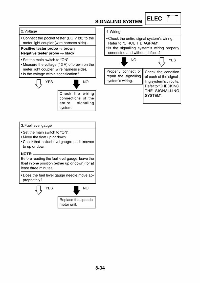
ELEC
8-34
SIGNALING SYSTEM
2.Voltage
• Connect the pocket tester (DC V 20) to themeter light coupler (wire harness side) .
Positive tester probe → brownNegative tester probe → black
• Set the main switch to “ON”.• Measure the voltage (12 V) of brown on themeter light coupler (wire harness side).
• Is the voltage within specification?
YES NO
Check the wiringconnections of theentire signalingsystem.
3.Fuel level gauge
• Set the main switch to “ON”.• Move the float up or down.• Check that the fuel level gauge needle movesto up or down.
NOTE:Before reading the fuel level gauge, leave thefloat in one position (either up or down) for atleast three minutes.
• Does the fuel level gauge needle move ap-propriately?
YES NO
Replace the speedo-meter unit.
4.Wiring
• Check the entire signal system’s wiring.Refer to “CIRCUIT DIAGRAM”.
• Is the signalling system’s wiring properlyconnected and without defects?
YESNO
Check the conditionof each of the signal-ling system’s circuits.Refer to “CHECKINGTHE SIGNALLINGSYSTEM”.
Properly connect orrepair the signallingsystem’s wiring.

ELEC
8-35
SIGNALING SYSTEMEAS00805
6. The clock/odometer fails to come on.
1.Voltage
• Connect the pocket tester (DC V 20) to theclock/odometer coupler (wire harness side)as shown.
Positive tester probe → red Negative tester probe → ground
• Set the main switch to “ON”.• Measure the voltage (12 V).• Is the voltage within specification?
YES NO
The wiring circuit fromthe main switch to theclock coupler is faultyand must be repaired.
2.Clock
• Check that the clock is operating properly.• When setting the clock after its power sourcehas been disconnected (e.g., when the bat-tery is removed), first set the clock to 1:00 AMand then to the correct time.
• Is the clock operating properly?
YESNO
This circuit is OK.Replace the clock/odometer.
L
P
B
L
Br
YDg Ch
G
SbGR
YDg
Ch
B
BR
Br

ELEC
8-36
COOLING SYSTEMEAS00807
COOLING SYSTEMCIRCUIT DIAGRAM
Main switch Fuse (main) Battery26 Thermo fan switch27 Fan28 Coolant thermo switch29 Fan Fuse
23
13
A
B21
5
G
21
32
25
PN K O L MR
27
26
29
19 20
16H
28
1222
17
8
F
18
11
30
10
6
79
35J
24
3
4
31
C DE
F
33
34
14 15
G
B
LW
LW
(NATURAL)
RW
BB
L
L
P
CLO
CK
OD
OM
ET
ER
LW
P
B R - W W
Y
LW
LGY
ON
Br BR BW
HANDLE SWITCH 2
HANDLESWITCH 1
LGW BRGW
WL
BR
W
Br Br
B
WR
CHECK
GR
Br OrBr
YB
Or
B YB
B
B
Br
Gy
OPENOFF
ONRBr
GyR
BW
Br
Br
R
Gy
L
R
LOCK
L
B
R
L
B
Or
YRR
L
Br
Gy
NO-CONNECTION
Y
GR
Ch
PG
BrWBY
DgLB Ch BrW
Dg
P
B
GY
LY
LB
-BW L
BW
L
GYY
GY
L
Br
LB
L
Br
L
GY
LB
L
Dg
Br
LR
B
B
B
B
B
Or
WL
WR
GW
B Y G
BR
(BLACK)
(BLACK)
Dg
Ch
Ch
LW
LW
LW
LW
Dg
Ch
Br Br
G
Ch Ch
LW
R
B
LW
LW
Dg
BR
NO-CONNECTIONBr
Ch
GW
WR
WL
NO-CONNECTION
B
NO-CONNECTION
(RED)
NO-CONNECTION
B
NO-CONNECTION
METERASSY.
Br
R
ANTI-THEFT
ALARM
(OPTION)
B
Dg
LW
LW
L
R
L
Br
RW
W
HEAD LIGHT ASSY.
Sb
Dg
BNO-CONNECTION
LW
LW
(RED)
L
Ch
G
B
Dg
Y
LW
L
Ch
G
B
Dg
Y
B
L
Y
Br
Y
GY
GY
Br
Br
YBYB
Br
L
LL
Y
Ch
G
DgCh
BWB
LW
B
Dg
Ch
ILLU
MI
Y
R
WIRE LEAD surANTI-THEFT 1 et 4
WIRE LEAD sur SIDE STAND
B
B
RW
TH
ER
MO
. MO
TO
R
TU
RN
L
TU
RN
R
HI B
EA
M
ILLU
MI
FU
EL
ME
TE
R
Br B
r
BrW
Br
W
BW
W W
W
W W
W (1)
Dg
(4)
Y
G
GR
W
W
W
Y
B
Br
Br
RNL
BrW
LW
Ch
LB
P
LO
HIPUSH
OFF
RW
LBBrGY
POS
OFF
START
OFF
LW
R
B
R
R
R
B
LW
BRW
LW
R
Y
B
Dg
GR
Dg
YR
LY
YR
BB
B
B
Ch
B
B
Or
WRWL
L
Y
LY
LYLY
LYLY
LY
LY
LY
LY
GY LBBrW
LY
Y G
BR
Br
L LB
B
Br
B
B
P
Dg
For LW/LWand LY/LY
BrGY
R
Sb
Sb
B
L
B
LY
B
B
LY
B(BLUE) (BLUE)
LY
LW
(OPTION)
BB
B
B
(BLUE)B
B
Ch
B

ELEC
8-37
COOLING SYSTEMEAS00808
TROUBLESHOOTING
• The radiator fan motor fails to turn.• The water temperature warning lightfails to light up when the engine is warm.
Check:1. main and radiator fan motor fuses2. battery3. main switch4. radiator fan motor5. thermo switch6. wiring connections
(the entire cooling system)
NOTE:• Before troubleshooting, remove the followingpart(-s):
1) Side covers2) Box and seat3) Battery cover4) Front cover• Troubleshoot with the following special tool (-s).
Pocket tester90890-03112
EASM0053
1. The radiator fan motor fails to turn.
1.Main and radiator fan motor fuses
• Check the fuses for continuity.Refer to “CHECKING THE FUSES” inchapter 3.
• Are the fuses OK?
• Clean the batteryterminals.
• Recharge or re-place the battery.
EAS00739
2.Battery
• Check the condition of the battery.Refer to “CHECKING THE BATTERY” inchapter 3.
Minimum open-circuit voltage12.8 V or more at 20°C
• Is the battery OK?
YES NO
EAS00749
3.Main switch
• Check the main switch for continuity.Refer to “CHECKING THE SWITCHES”.
• Is the main switch OK?
YES NO
Replace the mainswitch.
EAS00809
4.Radiator fan motor
• Disconnect the radiator fan motor couplerfrom the wire harness.
• Connect the battery (12 V) as shown.
Positive battery lead → black Negative battery lead → blue
Replace the fuses.
YES NO

ELEC
8-38
COOLING SYSTEM
EAS00811
6.Thermo switch
• Remove the thermo switch from the radiator.• Connect the pocket tester (Ω x 1) to thethermo switch as shown.
• Immerse the thermo switch in a containerfilled with coolant.
• Place a thermometer in the coolant.• Slowly heat the coolant, then let it cool downto the specified temperature.
• Check the thermo switch for continuity at thetemperatures indicated below.
A Thermo switch circuit “ON” B Thermo switch circuit “OFF”
• Does the thermo switch operate properly asdescribed above?
• Does the radiator fan motor turn?
YES NO
The radiator fan motoris faulty and must bereplaced.
WARNING • Handle the thermo switch with special
care.• Never subject the thermo switch to
strong shocks. If the thermo switch isdropped, replace it.
YES NO
Replace the thermoswitch.
B
A
EAS00813
7.Wiring
• Check the entire cooling system’s wiring.Refer to “CIRCUIT DIAGRAM”.
•Is the cooling system’s wiring properly con-nected and without defects?
YESNO
This circuit is OK.Properly connect orrepair the cooling sys-tem’s wiring.
EASM0053
2. The water temperature warning light fails tolight up when the engine is warm.
1.Main fuse
• Check the fuse for continuity.Refer to “CHECKING THE FUSES” inchapter 3.
• is the fuse OK?
Replace the fuse.
YES NO

ELEC
8-39
COOLING SYSTEM
• Clean the batteryterminals.
• Recharge or re-place the battery.
EAS00739
2.Battery
• Check the condition of the battery.Refer to “CHECKING THE BATTERY” inchapter 3.
Minimum open-circuit voltage12.8 V or more at 20°C
• Is the battery OK?
YES NO
EAS00749
3.Main switch
• Check the main switch for continuity.Refer to “CHECKING THE SWITCHES”.
• Is the main switch OK?
YES NO
Replace the mainswitch.
EAS00812
4.Temperature sender
• Remove the temperature sender from theradiator.Connect the pocket tester (Ω x 10) to thetemperature sender.
• Immerse the temperature sender in a con-tainer filled with coolant.
NOTE:Make sure the thermo switch terminals do notget wet.
• Place a thermometer in the coolant.• Slowly heat the coolant, and then let it coolto the specified temperature indicated in thetable.
• Check the thermo switch for continuity at thetemperatures indicated in the table.
Temperature sender resistance80°C: 47.5 ~ 56.8 Ω100°C: 26.2 ~ 29.3 Ω
WARNING • Handle the temperature sender with
special care.• Never subject the temperature sender to
strong shocks. If the temperature senderis dropped, replace it.
A Thermo switch circuit is open and thetemperature warning light is “OFF”
B Thermo switch circuit is closed and thetemperature warning light is “ON”
• Does the temperature sender operate prop-erly?
YES NO
Replace the tempera-ture sender.
EAS00813
5.Wiring (of the entire cooling system).
• Check the entire cooling system’s wiring.Refer to “CIRCUIT DIAGRAM”.
•Is the cooling system’s wiring properly con-nected and without defects?
YESNO
This circuit is OK.Properly connect orrepair the cooling sys-tem’s wiring.

ELEC
8-40
CARBURETOR HEATING SYSTEMEAS00820
CARBURETOR HEATING SYSTEMCIRCUIT DIAGRAM
Main switch Fuse (main) Battery30 Carburetor heater switch31 Carburetor heater
23
13
A
B21
5
G
21
32
25
PN K O L MR
27
26
29
19 20
16H
28
12
2217
8
F
18
11
30
10
6
79
35J
24
3
4
31
C DE
F
33
34
14 15
G
B
LW
LW
(NATURAL)
RW
BB
L
L
P
CLO
CK
OD
OM
ET
ER
LW
P
B R - W W
Y
LW
LGY
ON
Br BR BW
HANDLE SWITCH 2
HANDLESWITCH 1
LGW BRGW
WL
BR
W
Br Br
B
WR
CHECK
GR
Br OrBr
YB
Or
B YB
B
B
Br
Gy
OPENOFF
ONRBr
GyR
BW
Br
Br
R
Gy
L
R
LOCK
L
B
R
L
B
Or
YRR
L
Br
Gy
NO-CONNECTION
Y
GR
Ch
PG
BrWBY
DgLB Ch BrW
Dg
P
B
GY
LY
LB
-BW L
BW
L
GYY
GY
L
Br
LB
L
Br
L
GY
LB
L
Dg
Br
LR
B
B
B
B
B
Or
WL
WR
GW
B Y G
BR
(BLACK)
(BLACK)
Dg
Ch
Ch
LW
LW
LW
LW
Dg
Ch
Br Br
G
Ch Ch
LW
R
B
LW
LW
Dg
BR
NO-CONNECTIONBr
Ch
GW
WR
WL
NO-CONNECTION
B
NO-CONNECTION
(RED)
NO-CONNECTION
B
NO-CONNECTION
METERASSY.
Br
R
ANTI-THEFT
ALARM
(OPTION)
B
Dg
LW
LW
L
R
L
Br
RW
W
HEAD LIGHT ASSY.
Sb
Dg
BNO-CONNECTION
LW
LW
(RED)
L
Ch
G
B
Dg
Y
LW
L
Ch
G
B
Dg
Y
B
L
Y
Br
Y
GY
GY
Br
Br
YBYB
Br
L
LL
Y
Ch
G
DgCh
BWB
LW
B
Dg
Ch
ILLU
MI
Y
R
WIRE LEAD surANTI-THEFT 1 et 4
WIRE LEAD sur SIDE STAND
B
B
RW
TH
ER
MO
. MO
TOR
TU
RN
L
TU
RN
R
HI B
EA
M
ILLU
MI
FU
EL
ME
TE
R
Br B
r
BrW
Br
W
BW
W W
W
W W
W (1)
Dg
(4)
Y
G
GR
W
W
W
Y
B
Br
Br
RNL
BrW
LW
Ch
LB
P
LO
HIPUSH
OFF
RW
LBBrGY
POS
OFF
START
OFF
LW
R
B
R
R
R
B
LW
BRW
LW
R
Y
B
Dg
GR
Dg
YR
LY
YR
BB
B
B
Ch
B
B
Or
WRWL
L
Y
LY
LYLY
LYLY
LY
LY
LY
LY
GY LBBrW
LY
Y G
BR
Br
L LB
B
Br
B
B
P
Dg
For LW/LWand LY/LY
BrGY
R
Sb
Sb
B
L
B
LY
B
B
LY
B(BLUE) (BLUE)
LY
LW
(OPTION)
BB
B
B
(BLUE)B
B
Ch
B

ELEC
8-41
CARBURETOR HEATING SYSTEMEAS00821
TROUBLESHOOTING
The carburetor heating system fails tooperate.
Check:1. Main fuse2. Battery3. Main switch4. Thermo switch5. Carburetor heater6. Wiring (of the entire carburetor heating system)
NOTE:• Before troubleshooting, remove the followingpart(s):
1) Side covers2) Box and seat3) Battery cover• Troubleshoot with the following special tool(s).
Pocket tester90890-03112
EAS00738
1.Main fuse
• Check the main fuse for continuity.• Refer to “CHECKING THE FUSES” in chap-ter 3.
• Is the main fuse OK?
Replace the fuse.
YES NO
• Clean the batteryterminals.
• Recharge or re-place the battery.
EAS00739
2.Battery
• Check the condition of the battery.Refer to “CHECKING THE BATTERY” inchapter 3.
Minimum open-circuit voltage12.8 V or more at 20°C
• Is the battery OK?
YES NO
EAS00749
3.Main switch
• Check the main switch for continuity.Refer to “CHECKING THE SWITCHES”.
• Is the main switch OK?
YES NO
Replace the mainswitch.

ELEC
8-42
CARBURETOR HEATING SYSTEMEAS00823
4. Thermo switch
• Disconnect the thermo switch from the wireharness.
• Connect the pocket tester (Ω x 1) to thethermo switch lead.
Positive tester probe → black Negative tester probe → black
EAS00824
5.Carburetor heater
• Remove the carburetor heating element fromthe carburetor.
• Connect the pocket tester (Ω x 1) to thecarburetor heating element.
Positive tester probe →→→→→ heating element Negative tester probe → heating element
body
EAS00826
6. Wiring (of the entire carburetor heating system)
• Check the entire carburetor heating sys-tem’s wiringRefer to “CIRCUIT DIAGRAM”
• Is the carburetor heating system properlyconnected and without defects?
YES NO
Replace the thermoswitch.
YES NO
Replace the carbu-retor heating element.
YESNO
This circuit is OK.Properly connect orrepair the carburetorheating system’s wir-ing.
• Check the thermo switch for continuity at thetemperatures indicated below.
8¡C – 4¡C 19¡C – 3¡C
A COOL DOWNB HEAT UP
• Does the thermo switch operated properly ?
• Measure the carburetor heater resistance.
Carburetor heating elementresistance:
6 ~ 12 Ω at 20°C
• Is the carburetor heating element OK?

9TRBLSHTG

CHAPTER 9.TROUBLESHOOTING
STARTING FAILURE/ HARD STARTING ....................................................9-1ENGINE ...................................................................................................9-1FUEL SYSTEM ........................................................................................9-1ELECTRICAL SYSTEMS .........................................................................9-2
INCORRECT ENGINE IDLING SPEED .........................................................9-2ENGINE ...................................................................................................9-2FUEL SYSTEM ........................................................................................9-2ELECTRICAL SYSTEMS .........................................................................9-2
POOR MEDIUM-AND-HIGH-SPEED PERFORMANCE ...............................9-2ENGINE ...................................................................................................9-2FUEL SYSTEM ........................................................................................9-2
FAULTY CLUTCH .........................................................................................9-3ENGINE OPERATES BUT SCOOTER WILL NOT MOVE ......................9-3CLUTCH SLIPS .......................................................................................9-3POOR STARTING PERFORMANCE ......................................................9-3POOR SPEED PERFORMANCE ............................................................9-3
OVER HEATING ............................................................................................9-3ENGINE ...................................................................................................9-3COOLING SYSTEM .................................................................................9-3FUEL SYSTEM ........................................................................................9-3CHASSIS .................................................................................................9-3ELECTRICAL SYSTEMS .........................................................................9-3
OVERCOOLING ............................................................................................9-4COOLING SYSTEM .................................................................................9-4
POOR BRAKING ...........................................................................................9-4
FAULTY FRONT FORK LEGS ......................................................................9-4LEAKING OIL ...........................................................................................9-4MALFUNCTION .......................................................................................9-4
TRBLSHTG

UNSTABLE HANDLING ................................................................................9-5
FAULTY LIGHTING OR SIGNALING SYSTEM ............................................9-5HEADLIGHT DOES NOT LIGHT .............................................................9-5HEADLIGHT BULB BURNT OUT ............................................................9-5TAIL/BRAKE LIGHT DOES NOT LIGHT .................................................9-5TAIL/BRAKE LIGHT BULB BURNT OUT ................................................9-5TURN SIGNAL DOES NOT LIGHT ..........................................................9-5TURN SIGNAL BLINKS SLOWLY ...........................................................9-5TURN SIGNAL REMAINS LIT .................................................................9-6TURN SIGNAL BLINKS QUICKLY ..........................................................9-6HORN DOES NOT SOUND .....................................................................9-6
TRBLSHTG
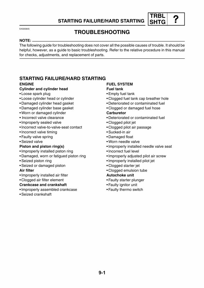
TRBLSHTG
9-1
STARTING FAILURE/HARD STARTINGEAS00845
TROUBLESHOOTINGNOTE:The following guide for troubleshooting does not cover all the possible causes of trouble. It should behelpful, however, as a guide to basic troubleshooting. Refer to the relative procedure in this manualfor checks, adjustments, and replacement of parts.
ENGINECylinder and cylinder head• Loose spark plug• Loose cylinder head or cylinder• Damaged cylinder head gasket• Damaged cylinder base gasket• Worn or damaged cylinder• Incorrect valve clearance• Improperly sealed valve• Incorrect valve-to-valve-seat contact• Incorrect valve timing• Faulty valve spring• Seized valvePiston and piston ring(s)• Improperly installed piston ring• Damaged, worn or fatigued piston ring• Seized piston ring• Seized or damaged pistonAir filter• Improperly installed air filter• Clogged air filter elementCrankcase and crankshaft• Improperly assembled crankcase• Seized crankshaft
STARTING FAILURE/HARD STARTINGFUEL SYSTEMFuel tank• Empty fuel tank• Clogged fuel tank cap breather hole• Deteriorated or contaminated fuel• Clogged or damaged fuel hoseCarburetor• Deteriorated or contaminated fuel• Clogged pilot jet• Clogged pilot air passage• Sucked-in air• Damaged float• Worn needle valve• Improperly installed needle valve seat• Incorrect fuel level• Improperly adjusted pilot air screw• Improperly installed pilot jet• Clogged starter jet• Clogged emulsion tubeAutochoke unit• Faulty starter plunger• Faulty ignitor unit• Faulty thermo switch

TRBLSHTG
9-2
STARTING FAILURE/HARD STARTING/INCORRECT ENGINE IDLING SPEED/
POOR MEDIUM-AND-HIGH-SPEED PERFORMANCE
ELECTRICAL SYSTEMSBattery• Improperly charged battery• Faulty batteryFuse(s)• Blown, damaged or incorrect fuse• Improperly installed fuseSpark plug• Incorrect spark plug gap• Incorrect spark plug heat range• Fouled spark plug• Worn or damaged electrode• Worn or damaged insulator• Faulty spark plug capIgnition coil• Broken or shorted primary or secondary coils• Faulty spark plug lead• Cracked or broken ignition coil body
Ignition system• Faulty ignition unit• Faulty pickup coil• Broken generator rotor woodruff key/slippedtiming
Switches and wiring• Faulty main switch• Broken or shorted wiring• Faulty front, rear or both brake switches• Faulty start switch• Improperly grounded circuit• Loose connectionsStarting system• Faulty starter motor• Faulty starter relay• Faulty starter clutch
EAS00847
INCORRECT ENGINE IDLING SPEEDENGINECylinder and cylinder head• Incorrect valve clearance• Damaged valve train componentsAir filter• Clogged air filter element
FUEL SYSTEMCarburetor• Faulty starter plunger• Loose or clogged pilot jet• Loose or clogged pilot air jet• Damaged or loose carburetor joint• Improperly adjusted engine idling speed(throttle stop screw)
• Improper throttle cable free play• Flooded carburetorAutochoke unit• Faulty starter plunger• Faulty ignitor unit
EAS00848
POOR MEDIUM-AND-HIGH-SPEED PERFORMANCERefer to “STARTING FAILURE/HARD STARTING” section.ENGINEAir filter• Clogged air filter element
FUEL SYSTEMCarburetor• Faulty diaphragm• Incorrect fuel level• Loose or clogged main jet
ELECTRICAL SYSTEMSBattery• Discharged battery• Faulty batterySpark plug• Incorrect spark plug gap• Incorrect spark plug heat range• Fouled spark plug• Worn or damaged electrode• Worn or damaged insulator• Faulty spark plug capIgnition coil• Faulty spark plug leadIgnition system• Faulty ignitor unit• Faulty pickup coil

TRBLSHTG
9-3
FAULTY CLUTCH/OVERHEATING
ENGINE OPERATES BUT SCOOTER WILLNOT MOVEV-belt• Bent, damaged or worn V-belt• Slipping V-beltPrimary pulley cam and primary pulley slider• Damaged or worn primary pulley cam• Damaged or worn primary pulley sliderClutch spring(s)• Damaged clutch springTransmission gear(s)• Damaged transmission gear
CLUTCH SLIPSClutch shoe spring(s)• Damaged, loose or worn clutch shoe springClutch shoe(s)• Damaged or worn clutch shoePrimary sliding sheave• Seized primary sliding sheave
EAS00853
FAULTY CLUTCH
EAS00855
OVERHEATINGENGINEClogged coolant passagesCylinder head and piston• Heavy carbon buildupEngine oil• Incorrect oil level• Incorrect oil viscosity• Inferior oil quality
COOLING SYSTEMCoolant• Low coolant levelRadiator• Leaking coolant system• Damaged or leaking radiator• Faulty radiator cap• Bent or damaged radiator finWater pump• Damaged or faulty water pumpThermostat• Thermostat stays closed
FUEL SYSTEMCarburetor• Incorrect main jet setting• Incorrect fuel level• Damaged or loose carburetor jointAir filter• Clogged air filter element
CHASSISBrake(s)• Dragging brake
ELECTRICAL SYSTEMSSpark plug• Incorrect spark plug gap• Incorrect spark plug heat rangeIgnition system• Faulty ignition unit
POOR STARTING PERFORMANCEV-belt• V-belt slips• Oil or grease on the V-beltPrimary sliding sheave• Faulty operation• Worn pin groove• Worn pinClutch shoe(s)• Bent, damaged or worn clutch shoe
POOR SPEED PERFORMANCEV-belt• Oil or grease on the V-beltPrimary pulley weight(s)• Faulty operation• Worn primary pulley weightPrimary fixed sheave• Worn primary fixed sheavePrimary sliding sheave• Worn primary sliding sheaveSecondary fixed sheave• Worn secondary fixed sheaveSecondary sliding sheave• Worn secondary sliding sheave

TRBLSHTG
9-4
OVERCOOLING/POOR BRAKING/
FAULTY FRONT FORK LEGSEAS00856
OVERCOOLINGCOOLING SYSTEM• Thermostat• Thermostat stays open
EAS00859
POOR BRAKINGDisc brake• Worn brake pad• Worn brake disc• Air in hydraulic brake system• Leaking brake fluid• Faulty brake caliper kit• Faulty brake caliper seal• Loose union bolt• Damaged brake hose• Oil or grease on the brake disc• Oil or grease on the brake pad• Incorrect brake fluid level
Drum brake• Worn brake shoe• Worn or rusty brake drum• Incorrect brake camshaft lever position• Incorrect brake shoe position• Damaged or fatigued brake shoe spring• Oil or grease on the brake shoe• Oil or grease on the brake drum• Broken brake torque rod• Improper brake lever adjustement
EAS00860
FAULTY FRONT FORK LEGSLEAKING OIL• Bent, damaged or rusty inner tube• Cracked or damaged outer tube• Improperly installed oil seal• Damaged oil seal lip• Incorrect oil level (high)• Loose damper rod assembly bolt• Damaged damper rod assembly bolt copperwasher
• Cracked or damaged cap bolt O-ring• Loose drain bolt• Damaged drain bolt gasket
MALFUNCTION• Bent or damaged inner tube• Bent or damaged outer tube• Damaged fork spring• Worn or damaged outer tube• Bent or damaged damper rod• Incorrect oil viscosity• Incorrect oil level

TRBLSHTG
9-5
UNSTABLE HANDLING/FAULTY LIGHTING OR SIGNALING SYSTEM
EAS00862
UNSTABLE HANDLINGHandlebar• Bent or improperly installed handlebarSteering head components• Improperly installed lower bracket(improperly tightened ring nut)
• Bent steering stem• Damaged ball bearing or bearing racFront fork leg(s)• Uneven oil levels (both front fork legs)• Unevenly tensioned fork spring (both front forklegs)
• Broken fork spring• Bent or damaged inner tube• Bent or damaged outer tubeSwingarm• Worn bearing or bushing• Bent or damaged swingarm
Rear shock absorber assembly• Faulty rear shock absorber spring• Leaking oil or gasTyres• Uneven tyre pressures (front and rear)• Incorrect tyre pressure• Uneven tyre wearWheels• Incorrect wheel balance• Deformed cast wheel• Damaged wheel bearing• Bent or loose wheel axle• Excessive wheel runoutFrame• Bent frame• Damaged steering head pipe• Improperly installed bearing race
HEADLIGHT DOES NOT LIGHT• Wrong headlight bulb• Too many electrical accessories• Hard charging• Incorrect connection• Improperly grounded circuit• Poor contacts (main or light switch)• Burnt-out headlight bulb
HEADLIGHT BULB BURNT OUT• Wrong headlight bulb• Faulty battery• Faulty rectifier/regulator• Improperly grounded circuit• Faulty main switch• Faulty light switch• Headlight bulb life expired
TAIL/BRAKE LIGHT DOES NOT LIGHT• Wrong tail/brake light bulb• Too many electrical accessories• Incorrect connection• Burnt-out tail/brake light bulb
TAIL/BRAKE LIGHT BULB BURNT OUT• Wrong tail/brake light bulb• Faulty battery• Incorrectly adjusted rear brake light switch• Tail/brake light bulb life expired
TURN SIGNAL DOES NOT LIGHT• Faulty turn signal switch• Faulty turn signal relay• Burnt-out turn signal bulb• Incorrect connection• Damaged or faulty wire harness• Improperly grounded circuit• Faulty battery• Blown, damaged or incorrect fuse
TURN SIGNAL BLINKS SLOWLY• Faulty turn signal relay• Faulty main switch• Faulty turn signal switch• Incorrect turn signal bulb• Faulty charging circuit
EAS00866
FAULTY LIGHTING OR SIGNALING SYSTEM

TRBLSHTG
9-6
TURN SIGNAL REMAINS LIT• Faulty turn signal relay• Burnt-out turn signal bulb
TURN SIGNAL BLINKS QUICKLY• Incorrect turn signal bulb• Faulty turn signal relay• Burnt-out turn signal bulb
HORN DOES NOT SOUND• Improperly adjusted horn• Damaged or faulty horn• Faulty main switch• Faulty horn switch• Faulty battery• Blown, damaged or incorrect fuse• Faulty wire harness
FAULTY LIGHTING OR SIGNALING SYSTEM

23
13
A
B21
5
G
21
32
25
PN K O L MR
27
26
29
19 20
16H
28
12
2217
8
F
18
11
30
10
6
79
35J
24
3
4
31
C DE
F
33
34
14 15
27
26
25
24
23
P
O
N
M
L
14
K
15
16
28
29
30
31
32
22
21
J
H
G
F
13
20
19
18
1
2
3
4
5
6
7
8
9
10
11
A
17
33
E
D
C
12
B
34
R
35
G
B
LW
LW
(NATURAL)
RW
BB
L
FAN
L
TH. SWITCH FAN
TH.SWITCH AUTO CHOKE
AUTO CHOKE
SENDER
P
CLO
CK
OD
OM
ET
ER
LW
P
TH. WATER INDICATOR
HIGH BEAM INDICATOR 12V-1.2W
FUEL METER
FLASHER INDICATOR L 12V-1.2W
FLASHER INDICATOR R 12V-1.2W
RR FLASHER L 12V-10W
FR FLASHER R 12V-21W
FR FLASHER L 12V-21W
POSITION LAMP 12V-5W
B
HEAD LIGHT 2X12V-35X35W
HEAD LIGHT ASSY.
R
METER LIGHT 2X12V-1.2W
- W W
Y
LW
LGY
ON
Br BR BW
HANDLE SWITCH 2
HANDLESWITCH 1
L
GW BRGW
WL
BR
W
Br Br
CDI MAGNETO
B
RR FLASHER R 12V-10W
TAIL/STOP LIGHT 12V-5/21W
HORN
TH. SWITCH WATER
FUSE FAN
TH.SWITCH CARB.HEATER
CARB.HEATER
ANTI THEFT UNIT ( OPTION )
WR
METER ASSY.
RELAY
REAR STOP SWITCH
FRONT STOP SWITCH
CHECK
GR
CDI UNIT
IGN COIL
SPARK PLUG
MAIN SWITCH ASSY.
FUSE(MAIN)
BATTERY
RECTIFIER/REGULATOR
STARTER RELAY
STARTING MOTOR
HANDLE SWITCH (2)
STARTER SWITCH
Br OrBr
YB
Or
B YB
FLASHER RELAY
B
B
Br
Gy
OPENOFF
ONRBr
GyR
BW
Br
Br
R
Gy
L
R
LOCK
L
B
R LIGTING SWITCH
L
B
Or
YRR
L
Br
Gy
NO-CONNECTION
Y
GR
Ch
PG
BrWBY
DgLB Ch BrW
Dg
P
B
GY
LY
LB
-BW L
BW
L
GYY
GY
L
Br
LB
L
Br
L
GY
LB
L
Dg
Br
LR
B
B
B
B
B
Or
WL
WR
GW
B Y G
BR
(BLACK)
(BLACK)
Dg
Ch
Ch
LW
LW
LW
LW
Dg
Ch
Br Br
G
Ch Ch
LW
R
B
LW
LW
Dg
BR
NO-CONNECTIONBr
Ch
GW
WR
WL
NO-CONNECTION
B
NO-CONNECTION
(RED)
NO-CONNECTION
B
NO-CONNECTION
METERASSY.
Br
R
ANTI-THEFT
ALARM
(OPTION)
B
Dg
LW
LW
L
R
L
Br
RW
W
HEAD LIGHT ASSY.
Sb
Dg
BNO-CONNECTION
LW
LW
(RED)
L
Ch
G
B
Dg
Y
LW
L
Ch
G
B
Dg
Y
B
L
Y
Br
Y
GY
GY
Br
Br
YBYB
Br
L
LL
Y
Ch
G
DgCh
BWB
LW
B
Dg
Ch
ILLU
MI
Y
R
WIRE LEAD ONANTI-THEFT 1 et 4
WIRE LEAD ON SIDE STAND
SENSOR SPEED
B
B
RW
TH
ER
MO
. MO
TO
R
TU
RN
L
TU
RN
R
HI B
EA
M
ILLU
MI
FU
EL
ME
TE
R
Br B
rBrW
Br
W
BW
W W
W
W W
W (1)
Dg
(4)
Y
G
GR
W
W
W
Y
B
FLASHER SWITCH
Br
DIMMER SWITCH
HORN SWITCH
HANDLE SWITCH (1)
Br
RNL
BrW
LW
Ch
LB
P
LO
HIPUSH
OFF
RW
LBBrGY
POS
OFF
START
OFF
LW
R
B
R
R
R
B
LW
BRW
LW
R
Y
B
Dg
GR
Dg
YR
LY
YR
BB
B
B
Ch
B
B
Or
WRWL
L
Y
LY
LYLY
LYLY
LY
LY
LY
LY
GY LBBrW
LY
Y G
BR
Br
L LB
B
Br
B
B
P
SIDE STAND SW. ( OPTION )
Dg
For LW/LWand LY/LY
BrGY
R
Sb
Sb
B
L
B
LY
B
B
LY
B(BLUE) (BLUE)
LY
LW
(OPTION)
BB
B
B
(BLUE)B
B
Ch
BLED ( OPTION )
CLOCK AND ODOMETER
XN125-150 WIRING DIAGRAM COLOR CODEB ............. black Sb ........... sky blue G / R ....... green / red R / L ....... red / blueBr ............ brown W ............ white G / W ...... green / white R / W ...... red / whiteCh........... chocolate Y ............. yellow G / Y ....... green / yellow R / Y ....... red / yellowDg........... dark green B / L ........ brack / blue L / B ........ blue / black W / B ...... white / blackG ............ green B / R ....... brack / red L / R ....... blue / red W / G ...... white / greenGy........... gray B / W ...... black / white L / W ....... blue / white W / Y ....... white / yellowL ............. blue B / Y ........ black / yellow L / Y ........ blue / yellow Y / B ....... yellow / blackO ............ orange Br / L ...... brown / blue O / R ....... orange / red Y / L ........ yellow / blueP ............. pink Br / R ...... brown / red R / B ....... red / blackR............. red Br / W ..... brown / white R / G ....... red / green