mb91919 fujitsu mcu programming kit mb91919-001 mcu programmer by connecting mb91919-001 mcu...
TRANSCRIPT
FUJITSU MICROELECTRONICS PACIFIC ASIA LTD DESIGN CENTRE 10/F, World Commerce Centre, 11 Canton Road, Tsim Sha Tsui, Kowloon, Hong Kong Tel: (852)2736-3232 Fax: (852)2314-4207
MB91919 FUJITSU MCU Programming Kit
Version 5.0
Table of Contents 1. Introduction......................................................................................................... 1
1.1 What is Fujitsu MCU Programming Kit? .......................................................................................1 1.2 Delivery of MCU Programming Kit...............................................................................................1 1.3 Definition of Programming Modes.................................................................................................2
1.3.1 Asynchronous Serial Programming.........................................................................................2 1.3.2 Synchronous Serial Programming ...........................................................................................2 1.3.3 Parallel Programming ..............................................................................................................2
1.4 Configurations of MCU Programming Kit .....................................................................................3 1.4.1 Asynchronous Serial Mode .....................................................................................................3 1.4.2 MB91919-001 MCU Programmer...........................................................................................4
1.5 Which Devices are programmable? ................................................................................................5 1.5.1 F2MC16LX Devices, Parallel Programming ...........................................................................5 1.5.2 F2MC16LX Devices, Serial Programming ..............................................................................6 1.5.3 Parallel OTP Socket from Sun Hayato, F2MC8L Devices ......................................................7 1.5.4 Socket from HKDC, F2MC8L Devices ...................................................................................8
1.6 Setting of MB91919-003 ................................................................................................................9 2. Installation ......................................................................................................... 10
2.1 System Requirements ................................................................................................................... 10 2.2 Software Setup.............................................................................................................................. 10 2.3 Hardware Setup ............................................................................................................................ 10
2.3.1 For MB91919-002 Asynchronous Serial Adapter ................................................................. 10 2.3.2 For MB91919-001 MCU Programmer .................................................................................. 11
3. Using MCU Programmer GUI.......................................................................... 12 3.1 Programming Wizard, Advanced Mode and Production Mode.................................................... 12 3.2 Programming Wizard ................................................................................................................... 12 3.3 Advanced Mode............................................................................................................................ 18
3.3.1 Overview ............................................................................................................................... 18 3.3.2 Device Selection .................................................................................................................... 19 3.3.3 File Operations ...................................................................................................................... 19 3.3.4 Memory Buffer Operations ................................................................................................... 20 3.3.5 Programming Operations....................................................................................................... 22 3.3.6 Message Box ......................................................................................................................... 25 3.3.7 Version Information .............................................................................................................. 25 3.3.8 Special Feature Pull-Down Menu.......................................................................................... 26
3.3.9 Reset and Quit Button................................................................................................................ 27 3.4 Production Mode .......................................................................................................................... 27
Appendix................................................................................................................ 29 Appendix A Precautions.................................................................................................................. 31
PC Interface Software..................................................................................................................... 31 On-board Programming.................................................................................................................. 31 MCU Programmer .......................................................................................................................... 31
Appendix B What is New in Programmer v4.0 ............................................................................. 32 1. Version Number ......................................................................................................................... 32 2. Compatibility.............................................................................................................................. 32 3. Configure File Updating............................................................................................................. 33 4. Auto Operation ........................................................................................................................... 33 5. Reset RAM Function .................................................................................................................. 34 6. Protection.................................................................................................................................... 35 7. Support New Device Type ......................................................................................................... 35 8. Target Zone Mapping ................................................................................................................. 35 9. Message for Action..................................................................................................................... 36 10. 8 bit ASYN Device Selection ................................................................................................... 37 11. Parameter Settings .................................................................................................................... 37
Appendix C Pins Assignment for Socket ........................................................................................ 38
1
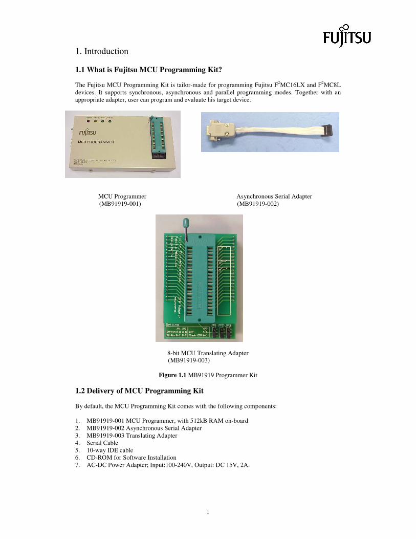
1. Introduction 1.1 What is Fujitsu MCU Programming Kit? The Fujitsu MCU Programming Kit is tailor-made for programming Fujitsu F2MC16LX and F2MC8L devices. It supports synchronous, asynchronous and parallel programming modes. Together with an appropriate adapter, user can program and evaluate his target device.
MCU Programmer Asynchronous Serial Adapter (MB91919-001) (MB91919-002)
8-bit MCU Translating Adapter
(MB91919-003)
Figure 1.1 MB91919 Programmer Kit 1.2 Delivery of MCU Programming Kit By default, the MCU Programming Kit comes with the following components: 1. MB91919-001 MCU Programmer, with 512kB RAM on-board 2. MB91919-002 Asynchronous Serial Adapter 3. MB91919-003 Translating Adapter 4. Serial Cable 5. 10-way IDE cable 6. CD-ROM for Software Installation 7. AC-DC Power Adapter; Input:100-240V, Output: DC 15V, 2A.
Additional components: Some F2MC8L devices are programmable by parallel adapters from Sun Hayato. Others required adapters from Fujitsu Microelectronics Pacific Asia Ltd, HKDC. Refer to table 3 and table 4 for details. For F2MC16LX devices, parallel adapters from HKDC are needed. Refer to table 1 for details. 1.3 Definition of Programming Modes 1.3.1 Asynchronous Serial Programming Connect the target chip to a PC directly through UART. Start the GUI on PC. On clicking the command button, PC sends out commands as well as data through the RS232 link. The target device, on receiving a specific command with data, performs corresponding action. This is called asynchronous serial programming. All members of F2MC16LX support this mode of programming. Some F2MC8L devices, however, do not support this mode. User should check on the hardware manual. By making use of MB91919-002 with connection using Appendix C, asynchronous programming can be performed. 1.3.2 Synchronous Serial Programming The target chip can be programmed by MB91919-001 through synchronous serial programming. Commands and data are transferred between programmer and target device through higher speed SIO interface. All F2MC16LX devices support this programming mode. For F2MC8L devices, user should check on the hardware manual to see if a particular device supports this programming mode. Pin assignment of connection is listed in Appendix C. 1.3.3 Parallel Programming By parallel programming mode, device is programmed through the 40-pin ZIF DIP socket. Commands and data are passed between programmer and target device in parallel. Therefore, programming speed is even faster than synchronous mode. All F2MC16LX devices are supported by this mode. Some F2MC8L devices do not support parallel mode. Special adapters are required for parallel programming. Refer to table1, table3 and table 4 for the details.
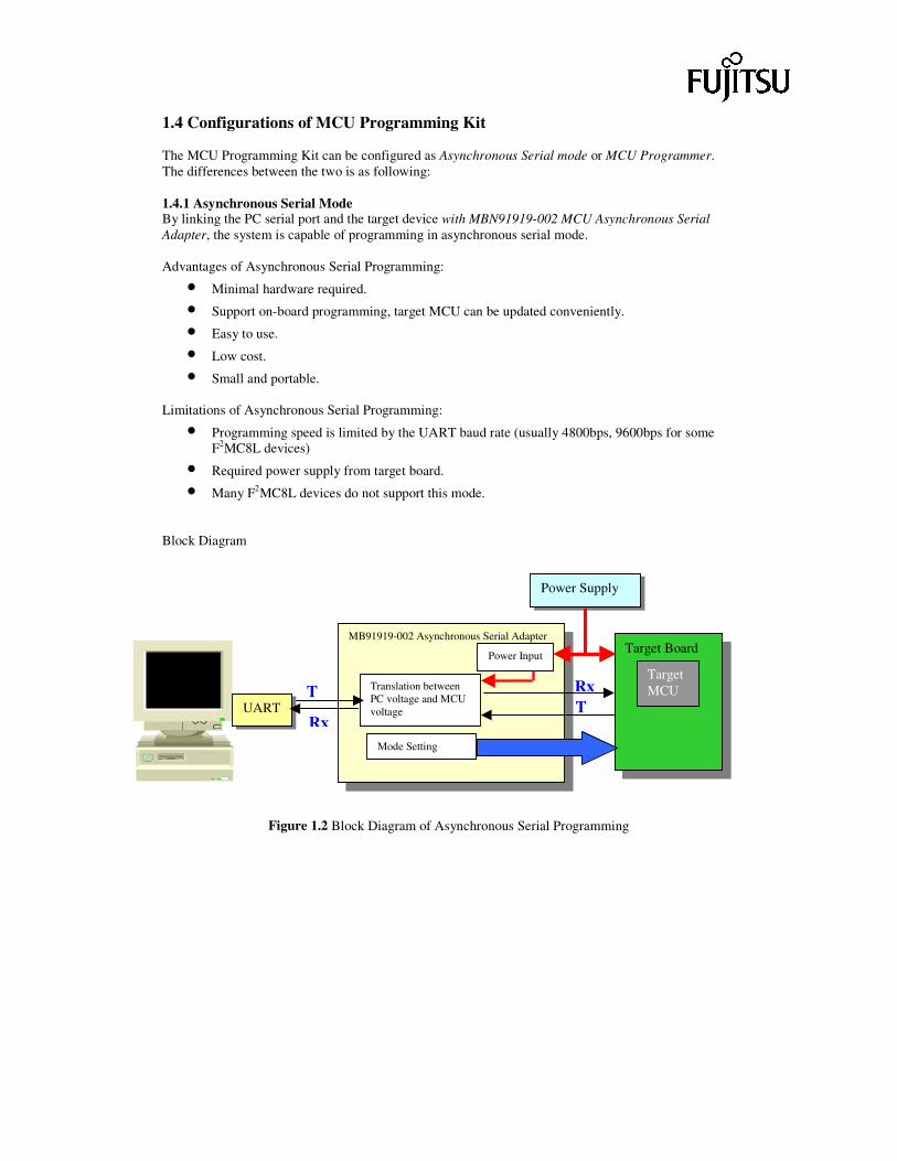
1.4 Configurations of MCU Programming Kit The MCU Programming Kit can be configured as Asynchronous Serial mode or MCU Programmer. The differences between the two is as following: 1.4.1 Asynchronous Serial Mode By linking the PC serial port and the target device with MBN91919-002 MCU Asynchronous Serial Adapter, the system is capable of programming in asynchronous serial mode. Advantages of Asynchronous Serial Programming:
• Minimal hardware required.
• Support on-board programming, target MCU can be updated conveniently.
• Easy to use.
• Low cost.
• Small and portable. Limitations of Asynchronous Serial Programming:
• Programming speed is limited by the UART baud rate (usually 4800bps, 9600bps for some F2MC8L devices)
• Required power supply from target board.
• Many F2MC8L devices do not support this mode.
Block Diagram
Figure 1.2 Block Diagram of Asynchronous Serial Programming
TRx
MB91919-002 Asynchronous Serial Adapter
Translation between PC voltage and MCU voltage
Mode Setting
Power Input
T
Target Board
Target MCU
UART
Power Supply
Rx

1.4.2 MB91919-001 MCU Programmer By connecting MB91919-001 MCU Programmer to the PC through serial port, the system can perform both parallel programming and synchronous serial programming. User can perform programming at higher speed. The MCU programmer has memory chips on board. There are four memory banks available. Each memory banks corresponding to a 512k-byte RAM. Currently, the software and hardware support 512k-byte memory on-board only. For later expansion, memory size of 1M, 1.5M or 2M bytes can be supported. Advantages of MB91919-001:
• Fast programming speed.
• Memory available on programmer. For programming several devices of same code, the code can be downloaded to the programmer once. Then, repeat programming the number of device needed.
• Support on-board programming.
• Support parallel programming.
• Support most members of F2MC16LX and F2MC8L MCU.
• MB91919-001 can be self-upgraded. Limitations of MB91919-001:
• Different adapters are required. For parallel programming, different adapters are required for different chip packages.
Block Diagram
Figure 1.3 Block Diagram of MB91919-001 Programming
MB91919-001 MCU Programmer
Twisted serial cable ZIF
Socket
On-board Programming Socket
Adapter Board for Parallel Chip Programming
Board for on-board programming
Power Supply
RAM Banks
Central MCU Com.
Unit
Power Control
Power Control
LED s
DIP Switches
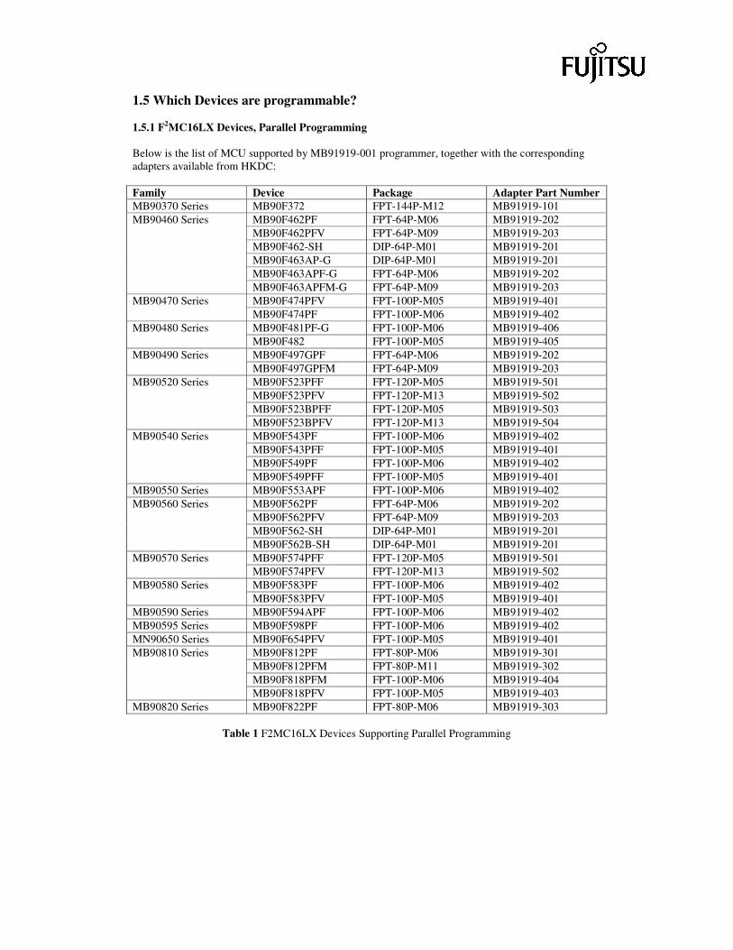
1.5 Which Devices are programmable? 1.5.1 F2MC16LX Devices, Parallel Programming Below is the list of MCU supported by MB91919-001 programmer, together with the corresponding adapters available from HKDC: Family Device Package Adapter Part Number MB90370 Series MB90F372 FPT-144P-M12 MB91919-101
MB90F462PF FPT-64P-M06 MB91919-202 MB90F462PFV FPT-64P-M09 MB91919-203 MB90F462-SH DIP-64P-M01 MB91919-201 MB90F463AP-G DIP-64P-M01 MB91919-201 MB90F463APF-G FPT-64P-M06 MB91919-202
MB90460 Series
MB90F463APFM-G FPT-64P-M09 MB91919-203 MB90F474PFV FPT-100P-M05 MB91919-401 MB90470 Series MB90F474PF FPT-100P-M06 MB91919-402 MB90F481PF-G FPT-100P-M06 MB91919-406 MB90480 Series MB90F482 FPT-100P-M05 MB91919-405 MB90F497GPF FPT-64P-M06 MB91919-202 MB90490 Series MB90F497GPFM FPT-64P-M09 MB91919-203 MB90F523PFF FPT-120P-M05 MB91919-501 MB90F523PFV FPT-120P-M13 MB91919-502 MB90F523BPFF FPT-120P-M05 MB91919-503
MB90520 Series
MB90F523BPFV FPT-120P-M13 MB91919-504 MB90F543PF FPT-100P-M06 MB91919-402 MB90F543PFF FPT-100P-M05 MB91919-401 MB90F549PF FPT-100P-M06 MB91919-402
MB90540 Series
MB90F549PFF FPT-100P-M05 MB91919-401 MB90550 Series MB90F553APF FPT-100P-M06 MB91919-402
MB90F562PF FPT-64P-M06 MB91919-202 MB90F562PFV FPT-64P-M09 MB91919-203 MB90F562-SH DIP-64P-M01 MB91919-201
MB90560 Series
MB90F562B-SH DIP-64P-M01 MB91919-201 MB90F574PFF FPT-120P-M05 MB91919-501 MB90570 Series MB90F574PFV FPT-120P-M13 MB91919-502 MB90F583PF FPT-100P-M06 MB91919-402 MB90580 Series MB90F583PFV FPT-100P-M05 MB91919-401
MB90590 Series MB90F594APF FPT-100P-M06 MB91919-402 MB90595 Series MB90F598PF FPT-100P-M06 MB91919-402 MN90650 Series MB90F654PFV FPT-100P-M05 MB91919-401
MB90F812PF FPT-80P-M06 MB91919-301 MB90F812PFM FPT-80P-M11 MB91919-302 MB90F818PFM FPT-100P-M06 MB91919-404
MB90810 Series
MB90F818PFV FPT-100P-M05 MB91919-403 MB90820 Series MB90F822PF FPT-80P-M06 MB91919-303
Table 1 F2MC16LX Devices Supporting Parallel Programming
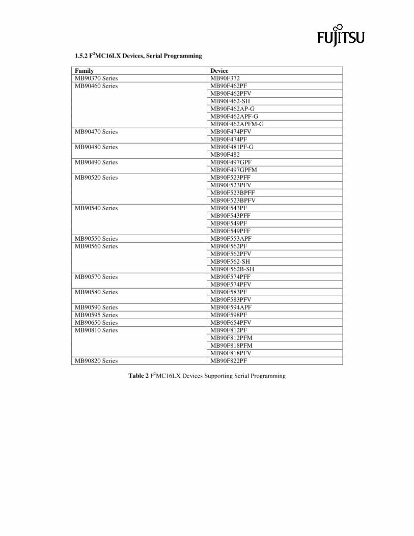
1.5.2 F2MC16LX Devices, Serial Programming Family Device MB90370 Series MB90F372
MB90F462PF MB90F462PFV MB90F462-SH MB90F462AP-G MB90F462APF-G
MB90460 Series
MB90F462APFM-G MB90F474PFV MB90470 Series MB90F474PF MB90F481PF-G MB90480 Series MB90F482 MB90F497GPF MB90490 Series MB90F497GPFM MB90F523PFF MB90F523PFV MB90F523BPFF
MB90520 Series
MB90F523BPFV MB90F543PF MB90F543PFF MB90F549PF
MB90540 Series
MB90F549PFF MB90550 Series MB90F553APF
MB90F562PF MB90F562PFV MB90F562-SH
MB90560 Series
MB90F562B-SH MB90F574PFF MB90570 Series MB90F574PFV MB90F583PF MB90580 Series MB90F583PFV
MB90590 Series MB90F594APF MB90595 Series MB90F598PF MB90650 Series MB90F654PFV
MB90F812PF MB90F812PFM MB90F818PFM
MB90810 Series
MB90F818PFV MB90820 Series MB90F822PF
Table 2 F2MC16LX Devices Supporting Serial Programming
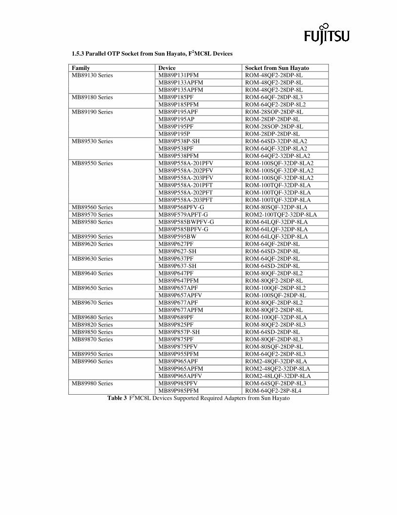
1.5.3 Parallel OTP Socket from Sun Hayato, F2MC8L Devices Family Device Socket from Sun Hayato
MB89P131PFM ROM-48QF2-28DP-8L MB89P133APFM ROM-48QF2-28DP-8L
MB89130 Series
MB89P135APFM ROM-48QF2-28DP-8L MB89P185PF ROM-64QF-28DP-8L3 MB89180 Series MB89P185PFM ROM-64QF2-28DP-8L2 MB89P195APF ROM-28SOP-28DP-8L MB89P195AP ROM-28DP-28DP-8L MB89P195PF ROM-28SOP-28DP-8L
MB89190 Series
MB89P195P ROM-28DP-28DP-8L MB89P538P-SH ROM-64SD-32DP-8LA2 MB89P538PF ROM-64QF-32DP-8LA2
MB89530 Series
MB89P538PFM ROM-64QF2-32DP-8LA2 MB89P558A-201PFV ROM-100SQF-32DP-8LA2 MB89P558A-202PFV ROM-100SQF-32DP-8LA2 MB89P558A-203PFV ROM-100SQF-32DP-8LA2 MB89P558A-201PFT ROM-100TQF-32DP-8LA MB89P558A-202PFT ROM-100TQF-32DP-8LA
MB89550 Series
MB89P558A-203PFT ROM-100TQF-32DP-8LA MB89560 Series MB89P568PFV-G ROM-80SQF-32DP-8LA MB89570 Series MB89F579APFT-G ROM2-100TQF2-32DP-8LA
MB89P585BWPFV-G ROM-64LQF-32DP-8LA MB89580 Series MB89P585BPFV-G ROM-64LQF-32DP-8LA
MB89590 Series MB89P595BW ROM-64LQF-32DP-8LA MB89P627PF ROM-64QF-28DP-8L MB89620 Series MB89P627-SH ROM-64SD-28DP-8L MB89P637PF ROM-64QF-28DP-8L MB89630 Series MB89P637-SH ROM-64SD-28DP-8L MB89P647PF ROM-80QF-28DP-8L2 MB89640 Series MB89P647PFM ROM-80QF2-28DP-8L MB89P657APF ROM-100QF-28DP-8L2 MB89650 Series MB89P657APFV ROM-100SQF-28DP-8L MB89P677APF ROM-80QF-28DP-8L2 MB89670 Series MB89P677APFM ROM-80QF2-28DP-8L
MB89680 Series MB89P689PF ROM-100QF-32DP-8LA MB89820 Series MB89P825PF ROM-80QF2-28DP-8L3 MB89850 Series MB89P857P-SH ROM-64SD-28DP-8L
MB89P875PF ROM-80QF-28DP-8L3 MB89870 Series MB89P875PFV ROM-80SQF-28DP-8L
MB89950 Series MB89P955PFM ROM-64QF2-28DP-8L3 MB89P965APF ROM2-48QF-32DP-8LA MB89P965APFM ROM2-48QF2-32DP-8LA
MB89960 Series
MB89P965APFV ROM2-48LQF-32DP-8LA MB89P985PFV ROM-64SQF-28DP-8L3 MB89980 Series MB89P985PFM ROM-64QF2-28P-8L4
Table 3 F2MC8L Devices Supported Required Adapters from Sun Hayato
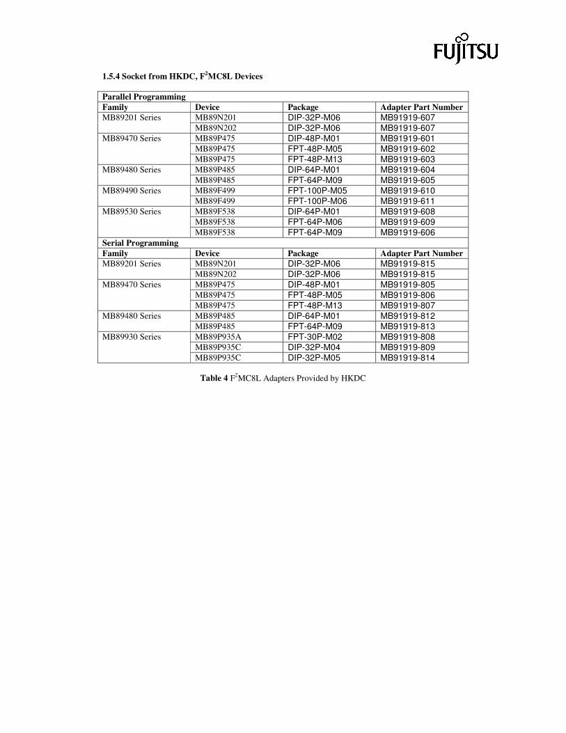
1.5.4 Socket from HKDC, F2MC8L Devices Parallel Programming Family Device Package Adapter Part Number
MB89N201 DIP-32P-M06 MB91919-607 MB89201 Series MB89N202 DIP-32P-M06 MB91919-607 MB89P475 DIP-48P-M01 MB91919-601 MB89P475 FPT-48P-M05 MB91919-602
MB89470 Series
MB89P475 FPT-48P-M13 MB91919-603 MB89P485 DIP-64P-M01 MB91919-604 MB89480 Series MB89P485 FPT-64P-M09 MB91919-605 MB89F499 FPT-100P-M05 MB91919-610 MB89490 Series MB89F499 FPT-100P-M06 MB91919-611 MB89F538 DIP-64P-M01 MB91919-608 MB89F538 FPT-64P-M06 MB91919-609
MB89530 Series
MB89F538 FPT-64P-M09 MB91919-606 Serial Programming Family Device Package Adapter Part Number
MB89N201 DIP-32P-M06 MB91919-815 MB89201 Series MB89N202 DIP-32P-M06 MB91919-815 MB89P475 DIP-48P-M01 MB91919-805 MB89P475 FPT-48P-M05 MB91919-806
MB89470 Series
MB89P475 FPT-48P-M13 MB91919-807 MB89P485 DIP-64P-M01 MB91919-812 MB89480 Series MB89P485 FPT-64P-M09 MB91919-813 MB89P935A FPT-30P-M02 MB91919-808 MB89P935C DIP-32P-M04 MB91919-809
MB89930 Series
MB89P935C DIP-32P-M05 MB91919-814
Table 4 F2MC8L Adapters Provided by HKDC
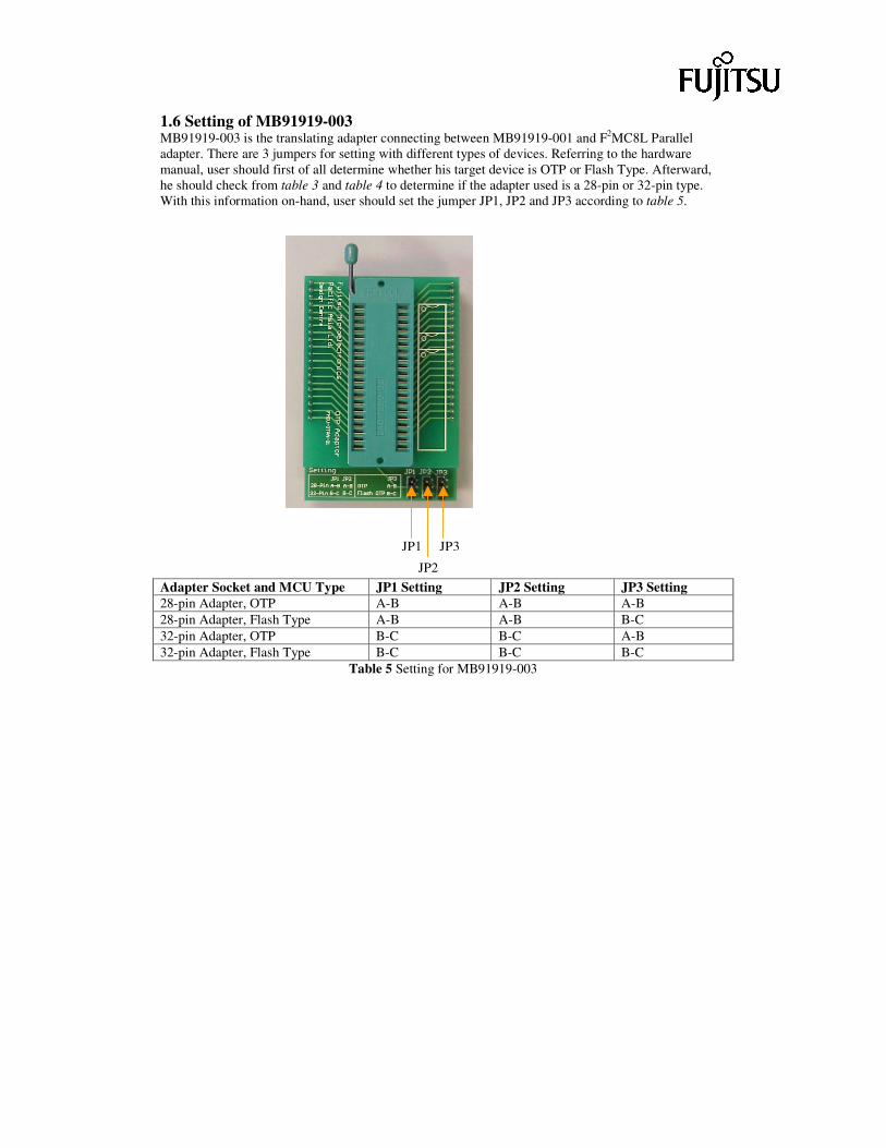
1.6 Setting of MB91919-003 MB91919-003 is the translating adapter connecting between MB91919-001 and F2MC8L Parallel adapter. There are 3 jumpers for setting with different types of devices. Referring to the hardware manual, user should first of all determine whether his target device is OTP or Flash Type. Afterward, he should check from table 3 and table 4 to determine if the adapter used is a 28-pin or 32-pin type. With this information on-hand, user should set the jumper JP1, JP2 and JP3 according to table 5.
Adapter Socket and MCU Type JP1 Setting JP2 Setting JP3 Setting 28-pin Adapter, OTP A-B A-B A-B 28-pin Adapter, Flash Type A-B A-B B-C 32-pin Adapter, OTP B-C B-C A-B 32-pin Adapter, Flash Type B-C B-C B-C
Table 5 Setting for MB91919-003
JP1
JP2
JP3
2. Installation 2.1 System Requirements The system requirements for using the kit is as following: CPU Type Pentium Processor or compatible Memory Size 16MB RAM Hard Disk Space More than 10M bytes free hard disk space Display Terminal VGA with 800x600 resolution or higher Com Port Equipped with RS-232 Compatible OS Win98, WinNT, Win2000 2.2 Software Setup To Install the Fujitsu MCU Programming Software, follow the following steps. 1. Turn on your computer. After the booting and startup process, insert the CD-ROM into the CD-
ROM Drive. 2. Explore the CD-ROM to the Programmer_V50_Setup folder. 3. Select and run Setup.exe. 4. The setup program would guide you throughout the following process. 2.3 Hardware Setup 2.3.1 For MB91919-002 Asynchronous Serial Adapter 1. Connect the DB-9 socket of the MB91919-002 Asynchronous Serial Adapter to a free RS-232 port
on PC. 2. Connect the other socket of the adapter to the target MCU board, which support on board
programming. 3. Connect the power supply to the target board. For the voltage input, it should follows the operating
voltage of the target board. 4. Turns on the Power supply. 5. Start MCU Programming GUI on the PC. 6. In the Connection Setup Window, check F2MC16LX Asynchronous Programming for target chip
belongs to F2MC16LX family. Check F2MC8L Asynchronous if the target device belongs to F2MC8L family.
7. For F2MC16LX device, select the crystal frequency and jump to step 9. 8. For F2MC8L device, choose your target device under the list box. 9. Press the connect button. 10. If the connection success, the PC would display "ASYN adapter found" in the corresponding COM
port. Jump to step 12. 11. If connection fail, the PC would display "Programmer not found" on all the COM ports. A window
would prompt out and ask the user to check the power, connection, and press RESET on the target board. User should check for the reason of communication failure.
12. Select either Advanced Mode, Wizard Mode or Production Mode Operation.
Caution: Please pay special attention to the voltage input. Never input voltage higher than the rated value of the target board. This would ruin both the target board as well as MB91919-002.
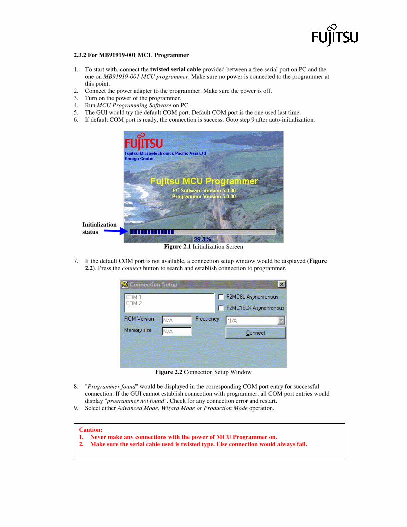
2.3.2 For MB91919-001 MCU Programmer 1. To start with, connect the twisted serial cable provided between a free serial port on PC and the
one on MB91919-001 MCU programmer. Make sure no power is connected to the programmer at this point.
2. Connect the power adapter to the programmer. Make sure the power is off. 3. Turn on the power of the programmer. 4. Run MCU Programming Software on PC. 5. The GUI would try the default COM port. Default COM port is the one used last time. 6. If default COM port is ready, the connection is success. Goto step 9 after auto-initialization.
Figure 2.1 Initialization Screen
7. If the default COM port is not available, a connection setup window would be displayed (Figure
2.2). Press the connect button to search and establish connection to programmer.
Figure 2.2 Connection Setup Window
8. "Programmer found" would be displayed in the corresponding COM port entry for successful
connection. If the GUI cannot establish connection with programmer, all COM port entries would display "programmer not found". Check for any connection error and restart.
9. Select either Advanced Mode, Wizard Mode or Production Mode operation.
Caution: 1. Never make any connections with the power of MCU Programmer on. 2. Make sure the serial cable used is twisted type. Else connection would always fail.
Initialization status
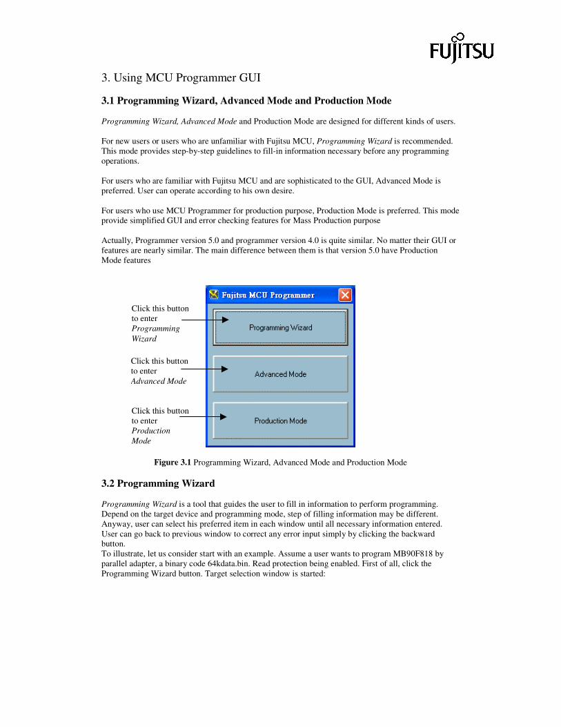
3. Using MCU Programmer GUI 3.1 Programming Wizard, Advanced Mode and Production Mode Programming Wizard, Advanced Mode and Production Mode are designed for different kinds of users. For new users or users who are unfamiliar with Fujitsu MCU, Programming Wizard is recommended. This mode provides step-by-step guidelines to fill-in information necessary before any programming operations. For users who are familiar with Fujitsu MCU and are sophisticated to the GUI, Advanced Mode is preferred. User can operate according to his own desire. For users who use MCU Programmer for production purpose, Production Mode is preferred. This mode provide simplified GUI and error checking features for Mass Production purpose Actually, Programmer version 5.0 and programmer version 4.0 is quite similar. No matter their GUI or features are nearly similar. The main difference between them is that version 5.0 have Production Mode features
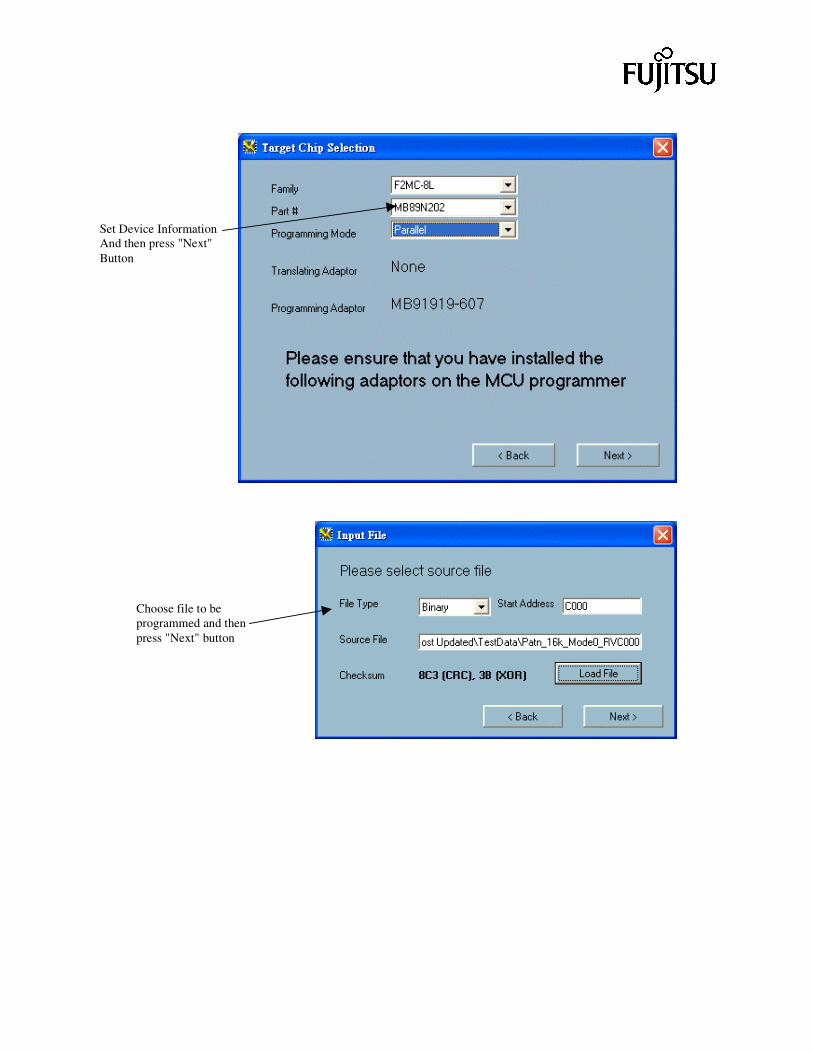
Figure 3.1 Programming Wizard, Advanced Mode and Production Mode 3.2 Programming Wizard Programming Wizard is a tool that guides the user to fill in information to perform programming. Depend on the target device and programming mode, step of filling information may be different. Anyway, user can select his preferred item in each window until all necessary information entered. User can go back to previous window to correct any error input simply by clicking the backward button. To illustrate, let us consider start with an example. Assume a user wants to program MB90F818 by parallel adapter, a binary code 64kdata.bin. Read protection being enabled. First of all, click the Programming Wizard button. Target selection window is started:
Click this button to enter Programming Wizard
Click this button to enter Advanced Mode
Click this button to enter Production Mode
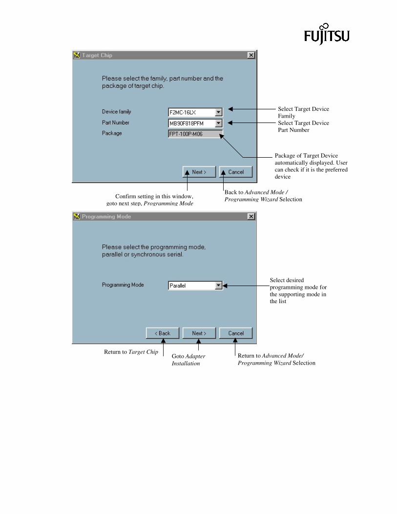
Select Target Device Family Select Target Device Part Number
Package of Target Device automatically displayed. User can check if it is the preferred device
Back to Advanced Mode / Programming Wizard Selection Confirm setting in this window,
goto next step, Programming Mode
Select desired programming mode for the supporting mode in the list
Return to Target Chip Goto Adapter Installation
Return to Advanced Mode/ Programming Wizard Selection
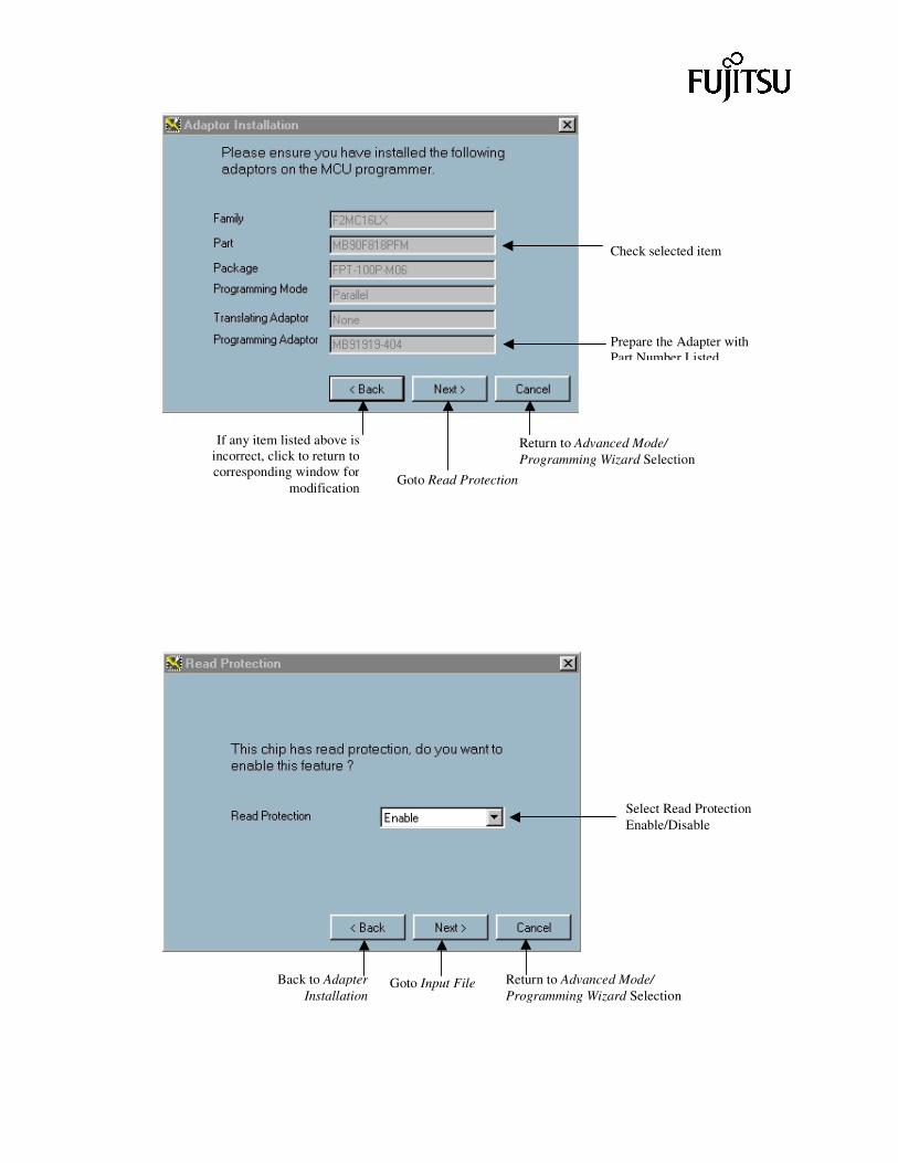
Select Read Protection Enable/Disable
Back to Adapter Installation
Goto Input File
Check selected item
Prepare the Adapter with Part Number Listed
If any item listed above is incorrect, click to return to corresponding window for
modification
Return to Advanced Mode/ Programming Wizard Selection
Goto Read Protection
Return to Advanced Mode/ Programming Wizard Selection
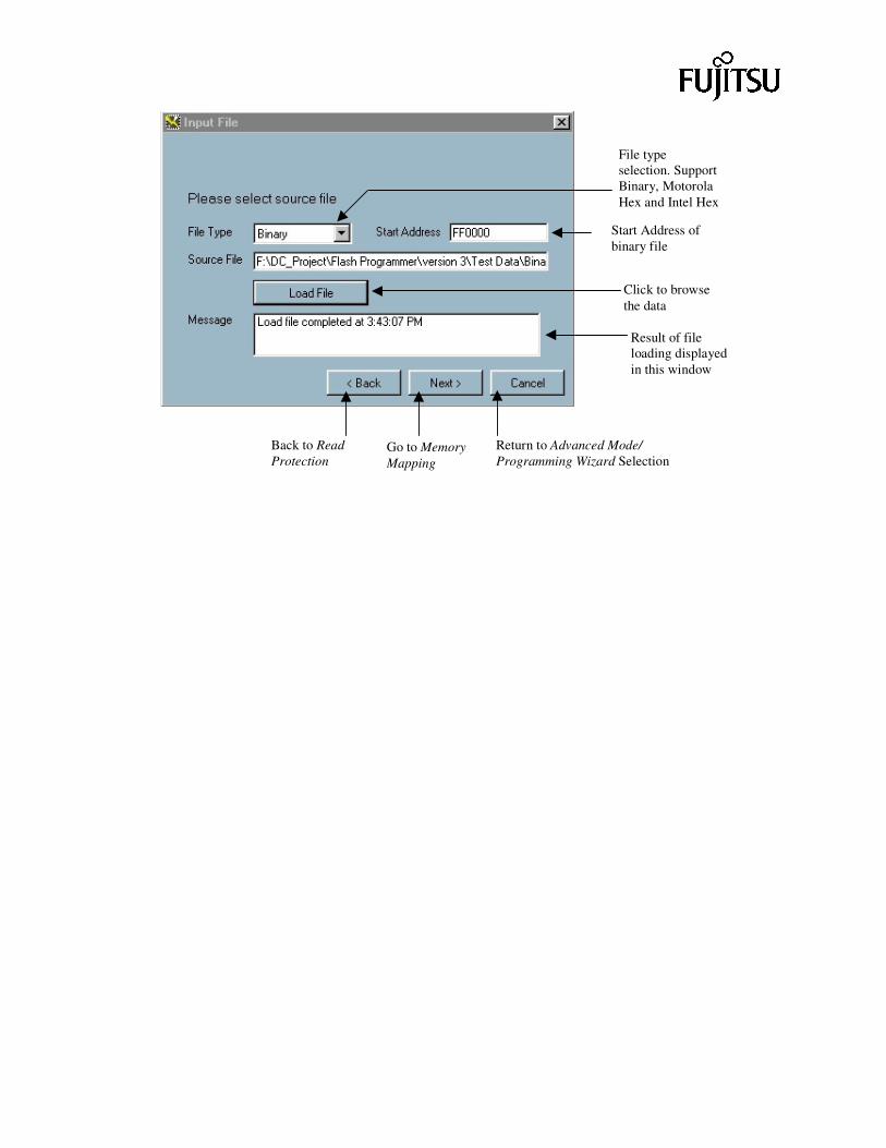
Start Address of binary file
File type selection. Support Binary, Motorola Hex and Intel Hex
Click to browse the data
Result of file loading displayed in this window
Back to Read Protection
Return to Advanced Mode/ Programming Wizard Selection
Go to Memory Mapping
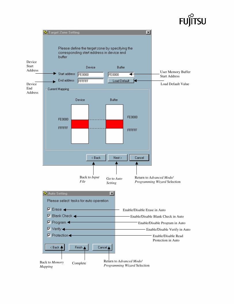
Device Start Address
Device End Address
User Memory Buffer Start Address
Load Default Value
Return to Advanced Mode/ Programming Wizard Selection
Back to Input File
Go to Auto Setting
Enable/Disable Erase in Auto
Enable/Disable Blank Check in Auto
Enable/Disable Program in Auto
Enable/Disable Verify in Auto
Enable/Disable Read Protection in Auto
Return to Advanced Mode/ Programming Wizard Selection
Back to Memory Mapping
Complete
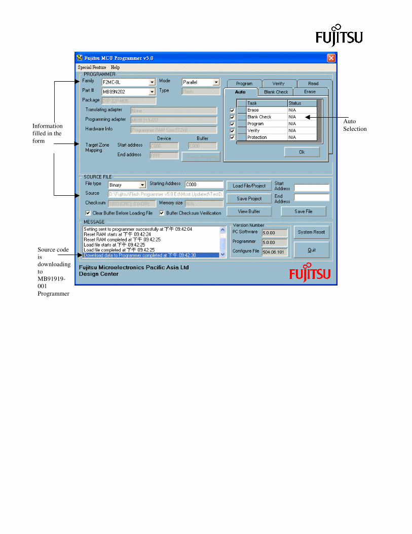
Source code is downloading to MB91919-001 Programmer
Information filled in the form
Auto Selection
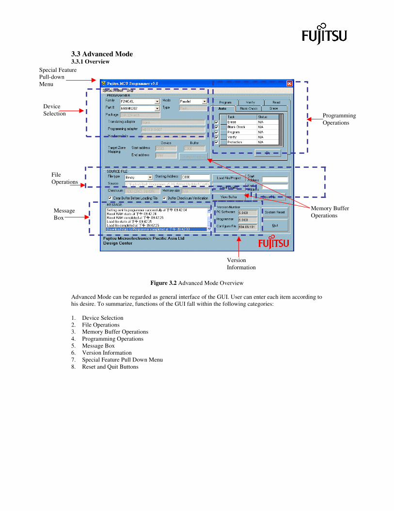
3.3 Advanced Mode 3.3.1 Overview
Figure 3.2 Advanced Mode Overview Advanced Mode can be regarded as general interface of the GUI. User can enter each item according to his desire. To summarize, functions of the GUI fall within the following categories: 1. Device Selection 2. File Operations 3. Memory Buffer Operations 4. Programming Operations 5. Message Box 6. Version Information 7. Special Feature Pull Down Menu 8. Reset and Quit Buttons
File Operations
Device Selection Programming
Operations
Memory Buffer Operations
Message Box
Version Information
Special Feature Pull-down Menu
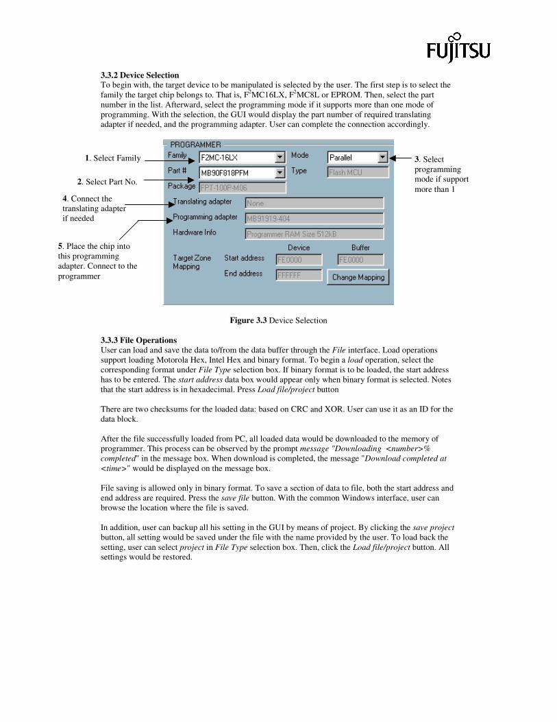
3.3.2 Device Selection To begin with, the target device to be manipulated is selected by the user. The first step is to select the family the target chip belongs to. That is, F2MC16LX, F2MC8L or EPROM. Then, select the part number in the list. Afterward, select the programming mode if it supports more than one mode of programming. With the selection, the GUI would display the part number of required translating adapter if needed, and the programming adapter. User can complete the connection accordingly.
Figure 3.3 Device Selection 3.3.3 File Operations User can load and save the data to/from the data buffer through the File interface. Load operations support loading Motorola Hex, Intel Hex and binary format. To begin a load operation, select the corresponding format under File Type selection box. If binary format is to be loaded, the start address has to be entered. The start address data box would appear only when binary format is selected. Notes that the start address is in hexadecimal. Press Load file/project button There are two checksums for the loaded data: based on CRC and XOR. User can use it as an ID for the data block. After the file successfully loaded from PC, all loaded data would be downloaded to the memory of programmer. This process can be observed by the prompt message "Downloading <number>% completed" in the message box. When download is completed, the message "Download completed at <time>" would be displayed on the message box. File saving is allowed only in binary format. To save a section of data to file, both the start address and end address are required. Press the save file button. With the common Windows interface, user can browse the location where the file is saved. In addition, user can backup all his setting in the GUI by means of project. By clicking the save project button, all setting would be saved under the file with the name provided by the user. To load back the setting, user can select project in File Type selection box. Then, click the Load file/project button. All settings would be restored.
1. Select Family
2. Select Part No.
3. Select programming mode if support more than 1
4. Connect the translating adapter if needed
5. Place the chip into this programming adapter. Connect to the programmer
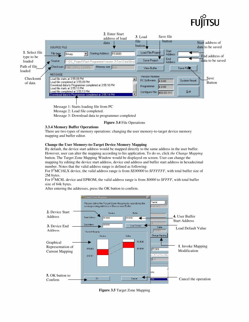
Figure 3.4 File Operations 3.3.4 Memory Buffer Operations There are two types of memory operations: changing the user memory-to-target device memory mapping and buffer editor. Change the User Memory-to-Target Device Memory Mapping By default, the device start address would be mapped directly to the same address in the user buffer. However, user can alter the mapping according to his application. To do so, click the Change Mapping button. The Target Zone Mapping Window would be displayed on screen. User can change the mapping by editing the device start address, device end address and buffer start address in hexadecimal number. Notes that the valid address range is defined as following: For F2MC16LX device, the valid address range is from $E00000 to $FFFFFF, with total buffer size of 2M bytes. For F2MC8L device and EPROM, the valid address range is from $0000 to $FFFF, with total buffer size of 64k bytes. After entering the addresses, press the OK button to confirm.
Figure 3.5 Target Zone Mapping
1. Select file type to be loaded
2. Enter Start address of load data
Path of file loaded
Message 1: Starts loading file from PC Message 2: Load file completed. Message 3: Download data to programmer completed
Checksum of data
3. Load file button
Save file button Start address of
data to be saved
End address of data to be saved
Save Button
2. Device Start Address
3. Device End Address
Graphical Representation of Current Mapping
5. OK button to Confirm Cancel the operation
1. Invoke Mapping Modification
Load Default Value
4. User Buffer Start Address
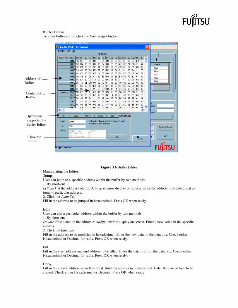
Buffer Editor To enter buffer editor, click the View Buffer button.
Figure 3.6 Buffer Editor Manipulating the Editor Jump User can jump to a specific address within the buffer by two methods: 1. By short-cut Left click at the address column: A jump window display on screen. Enter the address in hexadecimal to jump to particular address. 2. Click the Jump Tab Fill in the address to be jumped in hexadecimal. Press OK when ready. Edit User can edit a particular address within the buffer by two methods: 1. By short-cut Double-click a data in the editor: A modify window display on screen. Enter a new value in the specific address. 2. Click the Edit Tab Fill in the address to be modified in hexadecimal. Enter the new data on the data box. Check either Hexadecimal or Decimal for radix. Press OK when ready. Fill Fill in the start address and end address to be filled. Enter the data to fill in the data box. Check either Hexadecimal or Decimal for radix. Press OK when ready. Copy Fill in the source address as well as the destination address in hexadecimal. Enter the size of byte to be copied. Check either Hexadecimal or Decimal. Press OK when ready.
Address of Buffer
Content of Buffer
Operations Supported by Buffer Editor
Close the Editor
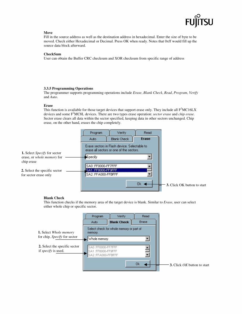
Move Fill in the source address as well as the destination address in hexadecimal. Enter the size of byte to be moved. Check either Hexadecimal or Decimal. Press OK when ready. Notes that 0xff would fill up the source data block afterward. CheckSum User can obtain the Buffer CRC checksum and XOR checksum from specific range of address 3.3.5 Programming Operations The programmer supports programming operations include Erase, Blank Check, Read, Program, Verify and Auto. Erase This function is available for those target devices that support erase only. They include all F2MC16LX devices and some F2MC8L devices. There are two types erase operation: sector erase and chip erase. Sector erase clears all data within the sector specified, keeping data in other sectors unchanged. Chip erase, on the other hand, erases the chip completely.
Blank Check This function checks if the memory area of the target device is blank. Similar to Erase, user can select either whole chip or specific sector.
1. Select Specify for sector erase, or whole memory for chip erase
2. Select the specific sector for sector erase only
3. Click OK button to start
1. Select Whole memory for chip, Specify for sector
2. Select the specific sector if specify is used.
3. Click OK button to start
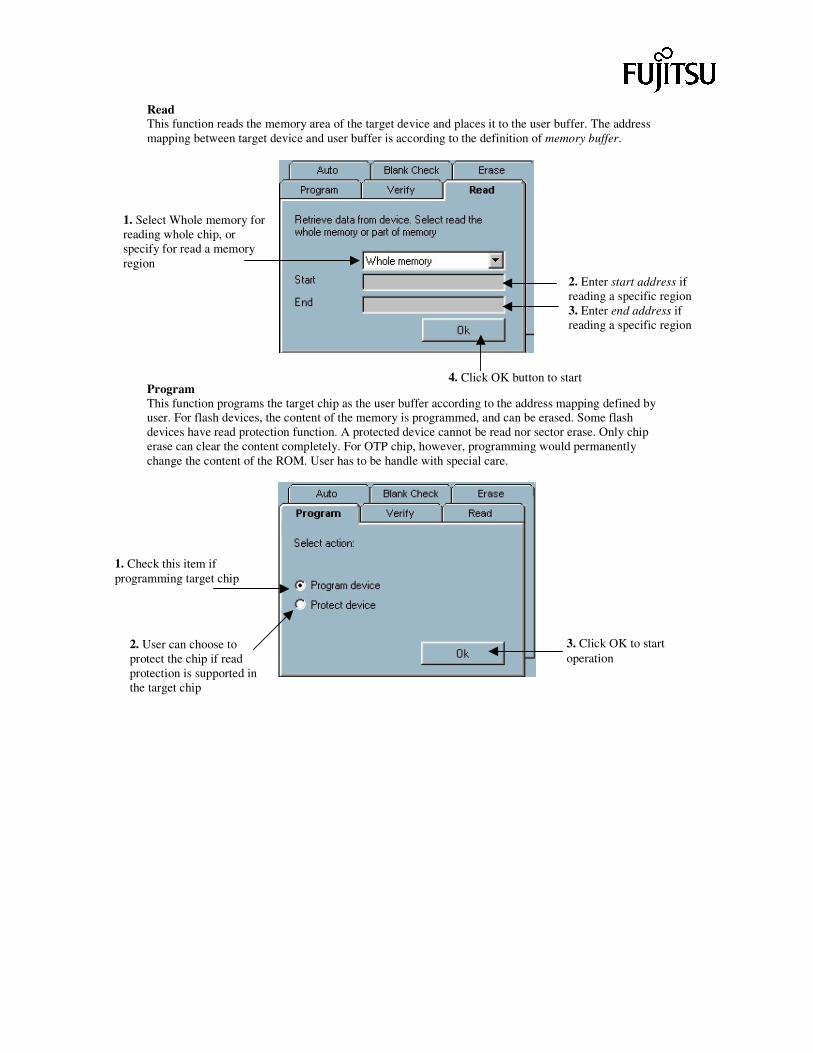
Read This function reads the memory area of the target device and places it to the user buffer. The address mapping between target device and user buffer is according to the definition of memory buffer.
Program This function programs the target chip as the user buffer according to the address mapping defined by user. For flash devices, the content of the memory is programmed, and can be erased. Some flash devices have read protection function. A protected device cannot be read nor sector erase. Only chip erase can clear the content completely. For OTP chip, however, programming would permanently change the content of the ROM. User has to be handle with special care.
1. Select Whole memory for reading whole chip, or specify for read a memory region
2. Enter start address if reading a specific region 3. Enter end address if reading a specific region
4. Click OK button to start
1. Check this item if programming target chip
2. User can choose to protect the chip if read protection is supported in the target chip
3. Click OK to start operation
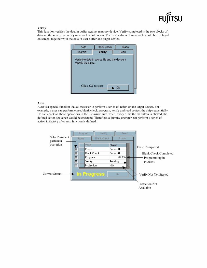
Verify This function verifies the data in buffer against memory device. Verify completed is the two blocks of data are the same, else verify mismatch would occur. The first address of mismatch would be displayed on screen, together with the data in user buffer and target device.
Auto Auto is a special function that allows user to perform a series of action on the target device. For example, a user can perform erase, blank check, program, verify and read protect the chip sequentially. He can check all these operations in the list inside auto. Then, every tiime the ok button is clicked, the defined action sequence would be executed. Therefore, a dummy operator can perform a series of action in factory after auto function is defined.
Select/unselect particular operation
Erase Completed
Blank Check Completed Programming in progress
Verify Not Yet Started
Protection Not Available
Current Status
Click OK to start
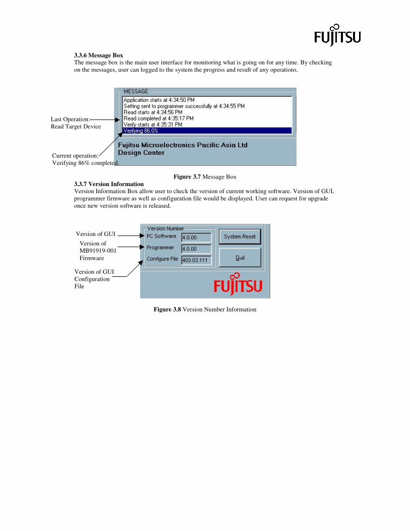
3.3.6 Message Box The message box is the main user interface for monitoring what is going on for any time. By checking on the messages, user can logged to the system the progress and result of any operations.
Figure 3.7 Message Box 3.3.7 Version Information Version Information Box allow user to check the version of current working software. Version of GUI, programmer firmware as well as configuration file would be displayed. User can request for upgrade once new version software is released.
Figure 3.8 Version Number Information
Current operation: Verifying 86% completed.
Last Operation: Read Target Device
Version of GUI
Version of MB91919-001 Firmware
Version of GUI Configuration File
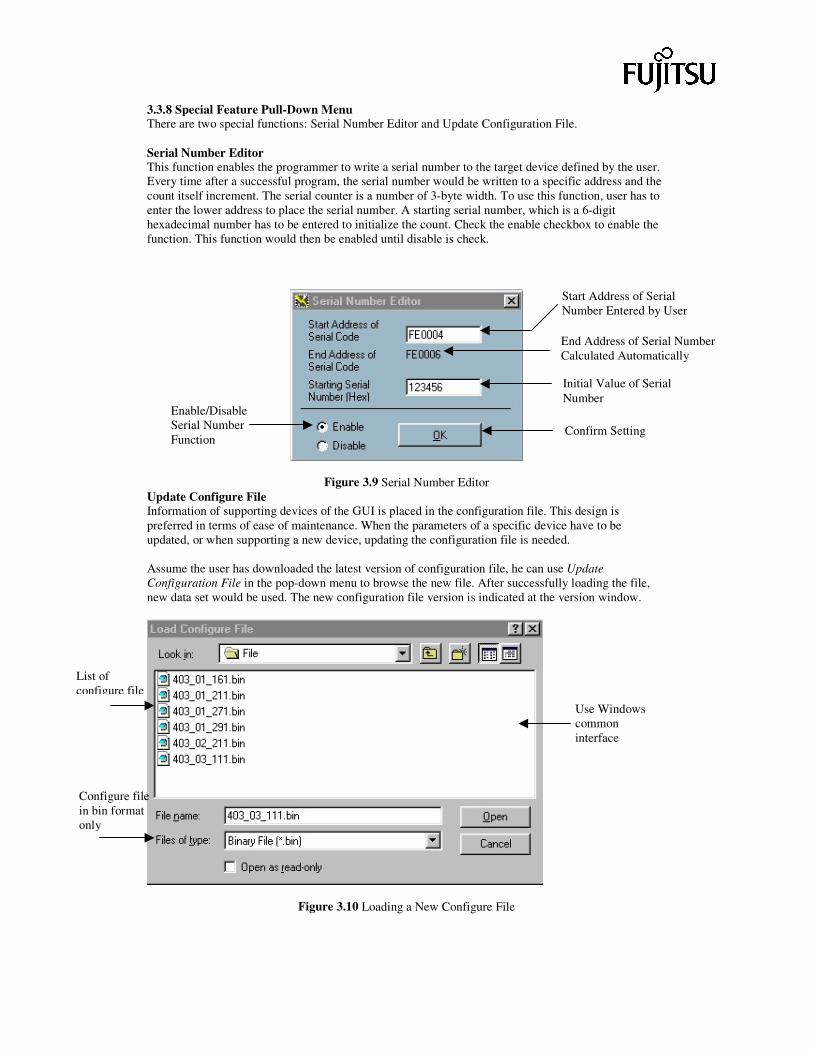
3.3.8 Special Feature Pull-Down Menu There are two special functions: Serial Number Editor and Update Configuration File. Serial Number Editor This function enables the programmer to write a serial number to the target device defined by the user. Every time after a successful program, the serial number would be written to a specific address and the count itself increment. The serial counter is a number of 3-byte width. To use this function, user has to enter the lower address to place the serial number. A starting serial number, which is a 6-digit hexadecimal number has to be entered to initialize the count. Check the enable checkbox to enable the function. This function would then be enabled until disable is check.
Figure 3.9 Serial Number Editor Update Configure File Information of supporting devices of the GUI is placed in the configuration file. This design is preferred in terms of ease of maintenance. When the parameters of a specific device have to be updated, or when supporting a new device, updating the configuration file is needed. Assume the user has downloaded the latest version of configuration file, he can use Update Configuration File in the pop-down menu to browse the new file. After successfully loading the file, new data set would be used. The new configuration file version is indicated at the version window.
Figure 3.10 Loading a New Configure File
Enable/Disable Serial Number Function
End Address of Serial Number Calculated Automatically
Initial Value of Serial Number
Start Address of Serial Number Entered by User
Confirm Setting
List of configure file
Use Windows common interface
Configure file in bin format only

3.3.9 Reset and Quit Button RESET Button Reset both the GUI and MB91919-001 programmer, if it is connected. QUIT Button Quit the GUI.
Figure 3.11 System Reset and Quit Buttons 3.4 Production Mode Production Mode is a mode that is for mass production. There are 2 options after choosing Production Mode: a. New Project b. Load Production Project For "New Project" option, it is for technical person to set all the parameters for mass production. For example, device to be programmed, programming method etc. Then the settings are saved as project file. For "Load Production Project" option, it is for workers. After choosing the project file, all the settings are loaded for programming. Then a very simple GUI is loaded for workers to minimize operation error. To illustrate, let us start with an example. Assume a user wants to program MB89N202 by parallel programming. First of all, click the "Production Mode" button and then "New Project" button
RESET Button
QUIT Button
Choose "New Project" option for making new project
Set Device Information And then press "Next" Button
Choose file to be programmed and then press "Next" button
Select operations to be done in programming And then press "Next" button
Set Target Zone Mapping.
Following GUI is the Production Mode GUI for workers, there is only one "START" button for programming new device.
Chip Information
Programming History
Program Status
"START" button to start program
Appendix Appendix A Precautions PC Interface Software 1 The files listed below are important configuration files for the PC software. They contain
parameters to perform different operations. They should not be corrupt.
File F2MC16LX.cfg F16ASYN.cfg F2MC8L.cfg F8ASYN.cfg EPROM.cfg Parameter_wTab.cfg TimeParameter_wTab.cfg
2 For binary file, the start address has to be specified. On-board Programming 1 On connecting the adapter between PC and target board, make sure the power supply from the
target board is turned off. 2 Avoid breaking the connection during operations such as programming is in process. 3 Ensure both the programmer and the target board is fixed and stable during programming in
process. 4 For ASYN programming, user should ensure that the apply voltage and mode pins are correct. MCU Programmer 1 Before turn on the power of the programmer, check all the connections are correct. 2 If parallel mode programming is used, place the target MCU chip into the adapter and make sure
correct orientation by comparing pin 1 of the chip and the marking on the adapter. Make sure that the chip is well placed in the adapter. That is, there is no electrical short between adjacent pins.
3 Never replace the chip with the adapter connected to the programmer. 4 For parallel programming, lock the ZIP handle before any operations. 5 Before programming devices, users are advised to check that the correct adapter is used. Wrong
adapters may resulted in damaging both the device to be programmed and the programmer. 6 Users are reminded to strictly follows the DIP Switch settings. Incorrect DIPSW setting can
destroy the programmer. 7 The 10-pin IDC connector for synchronous mode programming and the parallel adapter should not
be connected at the same time.
Appendix B What is New in Programmer v5.0 1. Version Number
As from above figure, new frame is added to indicate the version numbers. There are 3 version numbers. They are PC Software Version Number, Programmer Version Number and Configure File Version Number. PC Software Version Number
1. To indicate the version of the VB Software. 2. The format is in "X.X.XX". Current version is "5.0.00"
Programmer Version Number 1. To indicate the version of the MCU Programmer firmware. 2. The format is in "X.X.XX". 3. Current version is "5.0.00". For version 3.0 firmware, it will display "3.0.00" instead.
Configure File 1. To define all the settings of the supported devices. 2. The format of configure file version number is in "5YY.MM.DDN" 3. YY, MM, and DD indicate the year, month, day of the configure file released. 4. N indicates current file is the Nth version released on same day.
2. Compatibility
i. For PC software 4.0.00 onward, it can upward and downward compatible to programmer firmware with version number "5.X.XX", "4.X.XX" and "3.0.00".
ii. However, PC software and MCU firmware may not be fully compatible. It depends on their versions.
iii. After selecting the device, the PC software will determine which functions can be supported or cannot be supported for the existing configuration.
iv. In case there are unsupported function, message box will prompt to indicate what function cannot be supported and disable corresponding actions (Auto, Blank Check, Erase, Program, Verify and Read).
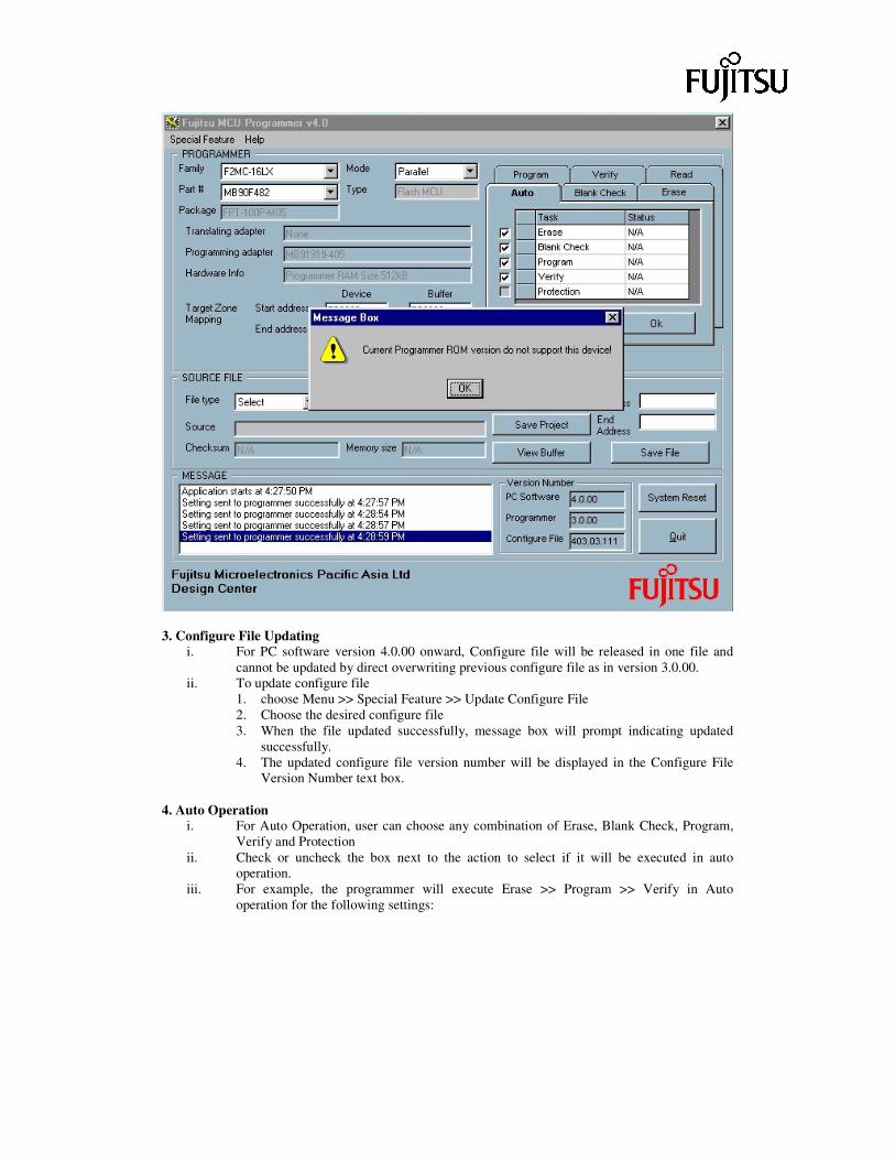
v. For example, all functions are not supported for the configuration (PC: 4.0.00, Firmware: 3.0.00, device: MB90F482). In this case, a message box will prompt out as below and all actions are disable.
3. Configure File Updating
i. For PC software version 4.0.00 onward, Configure file will be released in one file and cannot be updated by direct overwriting previous configure file as in version 3.0.00.
ii. To update configure file 1. choose Menu >> Special Feature >> Update Configure File 2. Choose the desired configure file 3. When the file updated successfully, message box will prompt indicating updated
successfully. 4. The updated configure file version number will be displayed in the Configure File
Version Number text box.
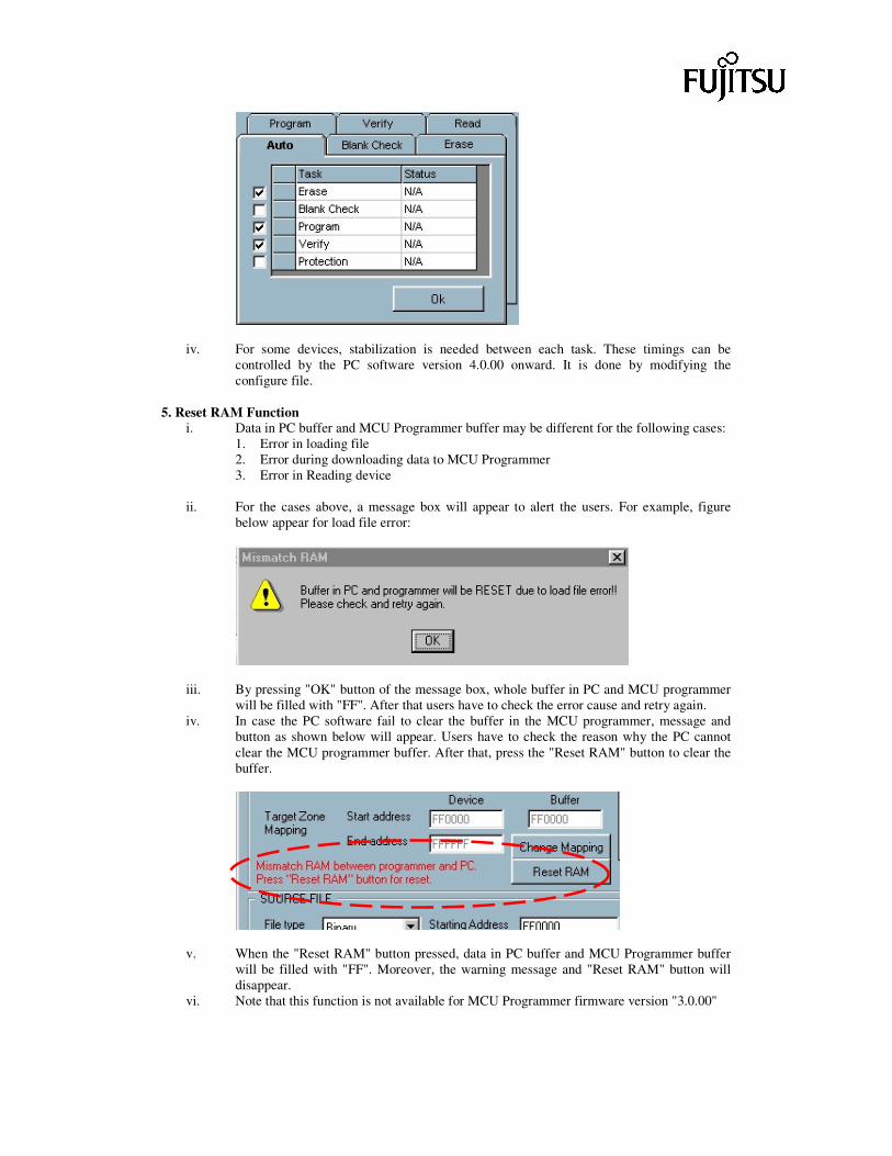
4. Auto Operation i. For Auto Operation, user can choose any combination of Erase, Blank Check, Program,
Verify and Protection ii. Check or uncheck the box next to the action to select if it will be executed in auto
operation. iii. For example, the programmer will execute Erase >> Program >> Verify in Auto
operation for the following settings:
iv. For some devices, stabilization is needed between each task. These timings can be controlled by the PC software version 4.0.00 onward. It is done by modifying the configure file.
5. Reset RAM Function
i. Data in PC buffer and MCU Programmer buffer may be different for the following cases: 1. Error in loading file 2. Error during downloading data to MCU Programmer 3. Error in Reading device
ii. For the cases above, a message box will appear to alert the users. For example, figure below appear for load file error:
iii. By pressing "OK" button of the message box, whole buffer in PC and MCU programmer will be filled with "FF". After that users have to check the error cause and retry again.
iv. In case the PC software fail to clear the buffer in the MCU programmer, message and button as shown below will appear. Users have to check the reason why the PC cannot clear the MCU programmer buffer. After that, press the "Reset RAM" button to clear the buffer.
v. When the "Reset RAM" button pressed, data in PC buffer and MCU Programmer buffer will be filled with "FF". Moreover, the warning message and "Reset RAM" button will disappear.
vi. Note that this function is not available for MCU Programmer firmware version "3.0.00"
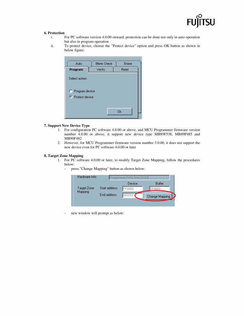
6. Protection i. For PC software version 4.0.00 onward, protection can be done not only in auto operation
but also in program operation ii. To protect device, choose the "Protect device" option and press OK button as shown in
below figure:
7. Support New Device Type 1. For configuration PC software 4.0.00 or above, and MCU Programmer firmware version
number 4.0.00 or above, it support new device type MB89F538, MB89P485 and MB90F482
2. However, for MCU Programmer firmware version number 3.0.00, it does not support the new device even for PC software 4.0.00 or later
8. Target Zone Mapping
1. For PC software 4.0.00 or later, to modify Target Zone Mapping, follow the procedures below: - press "Change Mapping" button as shown below:
- new window will prompt as below:
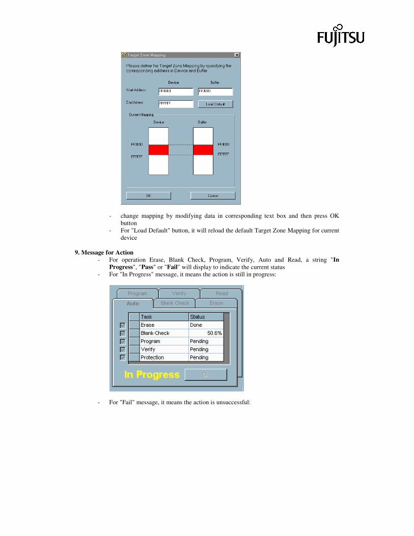
- change mapping by modifying data in corresponding text box and then press OK
button - For "Load Default" button, it will reload the default Target Zone Mapping for current
device 9. Message for Action
- For operation Erase, Blank Check, Program, Verify, Auto and Read, a string "In Progress", "Pass" or "Fail" will display to indicate the current status
- For "In Progress" message, it means the action is still in progress:
- For "Fail" message, it means the action is unsuccessful:
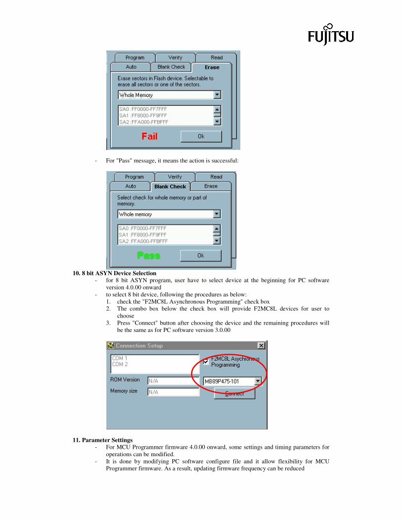
- For "Pass" message, it means the action is successful:
10. 8 bit ASYN Device Selection
- for 8 bit ASYN program, user have to select device at the beginning for PC software version 4.0.00 onward
- to select 8 bit device, following the procedures as below: 1. check the "F2MC8L Asynchronous Programming" check box 2. The combo box below the check box will provide F2MC8L devices for user to
choose 3. Press "Connect" button after choosing the device and the remaining procedures will
be the same as for PC software version 3.0.00
11. Parameter Settings - For MCU Programmer firmware 4.0.00 onward, some settings and timing parameters for
operations can be modified. - It is done by modifying PC software configure file and it allow flexibility for MCU
Programmer firmware. As a result, updating firmware frequency can be reduced
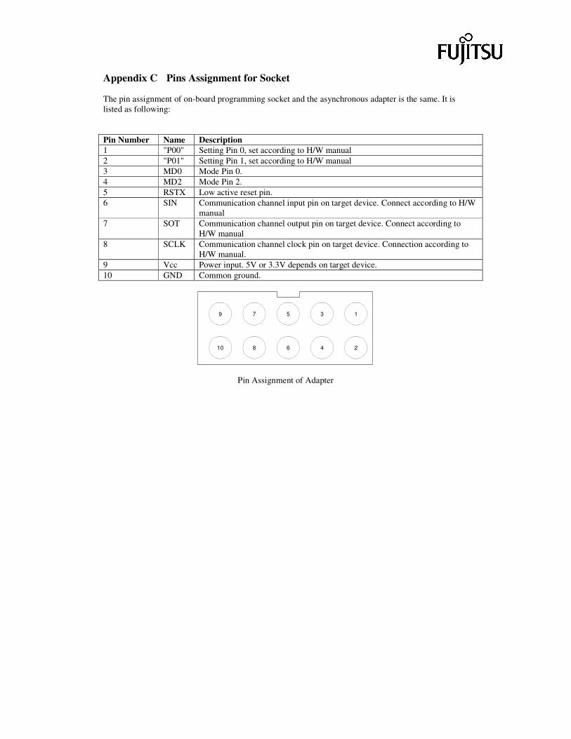
Appendix C Pins Assignment for Socket The pin assignment of on-board programming socket and the asynchronous adapter is the same. It is listed as following: Pin Number Name Description 1 "P00" Setting Pin 0, set according to H/W manual 2 "P01" Setting Pin 1, set according to H/W manual 3 MD0 Mode Pin 0. 4 MD2 Mode Pin 2. 5 RSTX Low active reset pin. 6 SIN Communication channel input pin on target device. Connect according to H/W
manual 7 SOT Communication channel output pin on target device. Connect according to
H/W manual 8 SCLK Communication channel clock pin on target device. Connection according to
H/W manual. 9 Vcc Power input. 5V or 3.3V depends on target device. 10 GND Common ground.
9 7 5 3 1
246810
Pin Assignment of Adapter