mazda3 electrical wiring diagram
DESCRIPTION
Mazda3 Electrical Wiring DiagramTRANSCRIPT
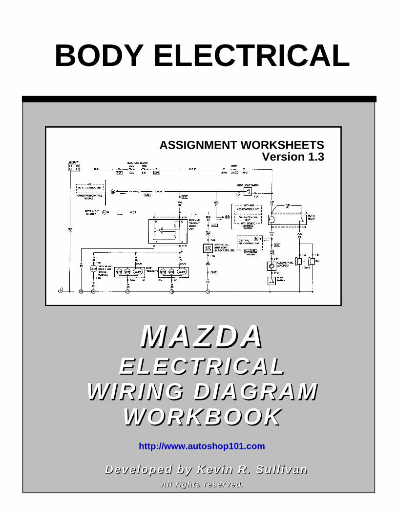
BODY ELECTRICAL
MAZDAMAZDAELECTRICALELECTRICAL
WIRING DIAGRAMWIRING DIAGRAMWORKBOOKWORKBOOK http://www.autoshop101.com
Developed by Kevin R. SullivanDeveloped by Kevin R. SullivanAll rights reserved.All rights reserved.
ASSIGNMENT WORKSHEETSVersion 1.3
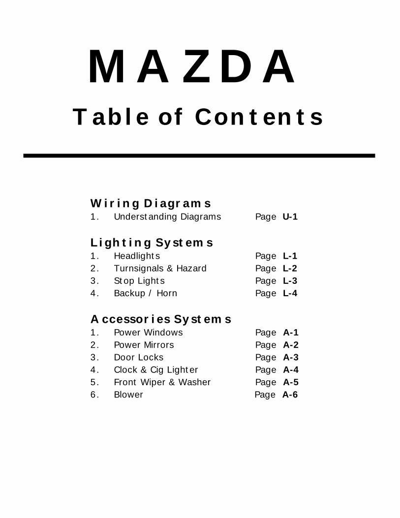
MAZDATable of Contents
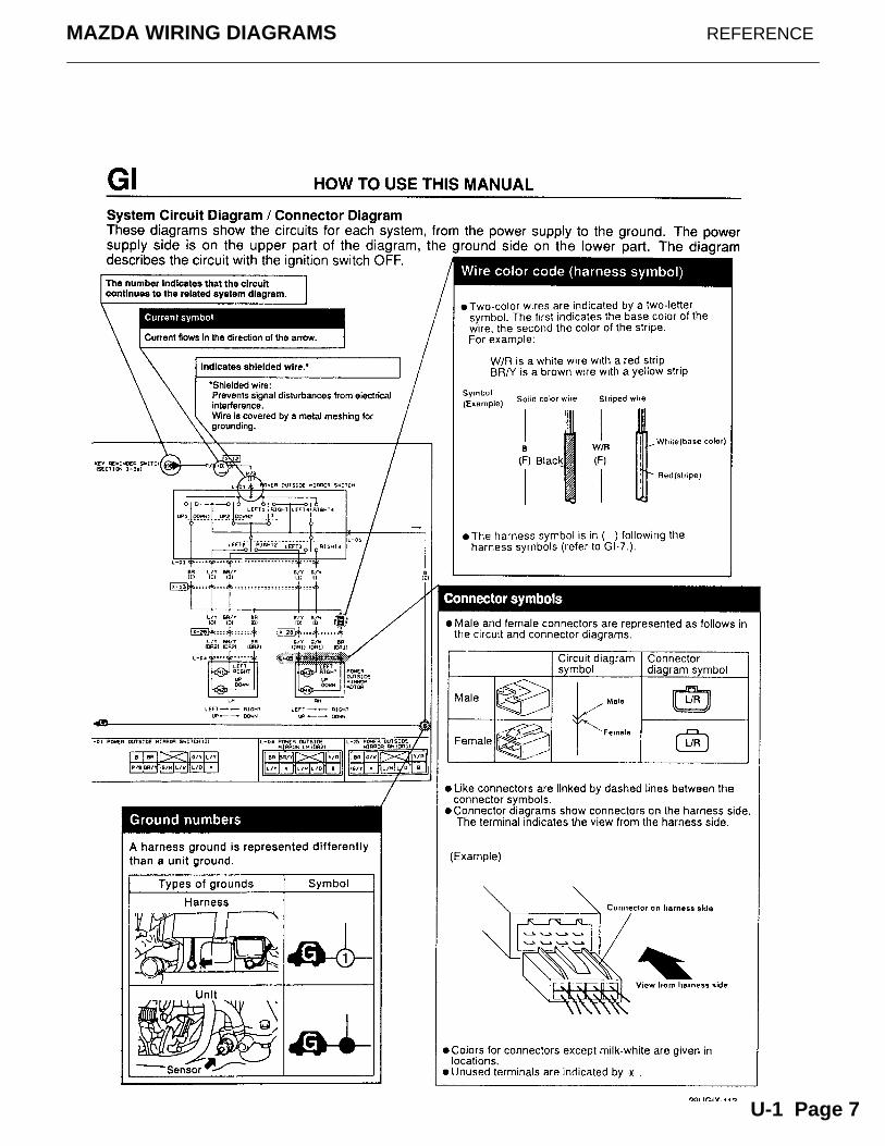
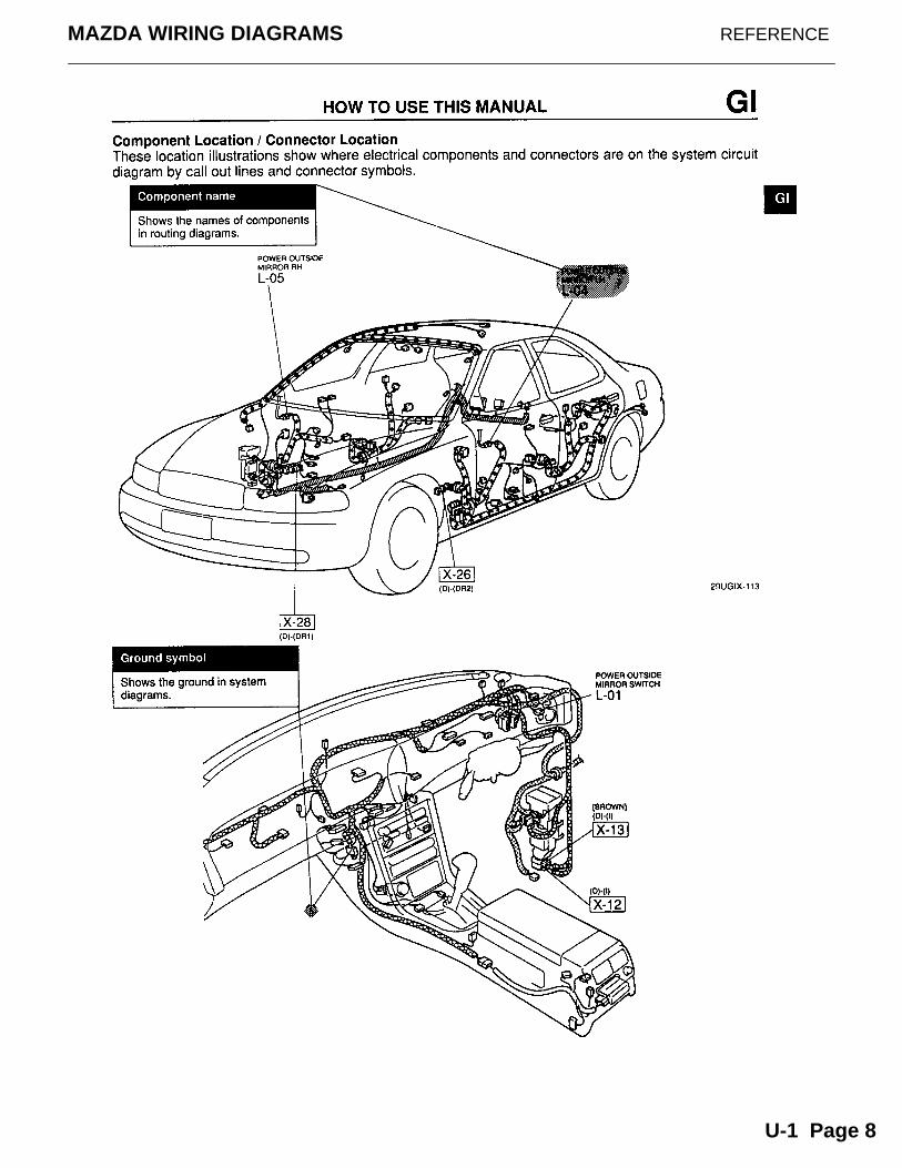
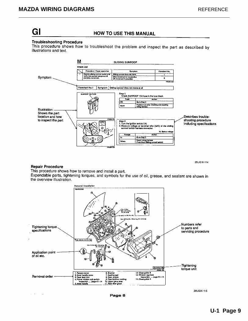
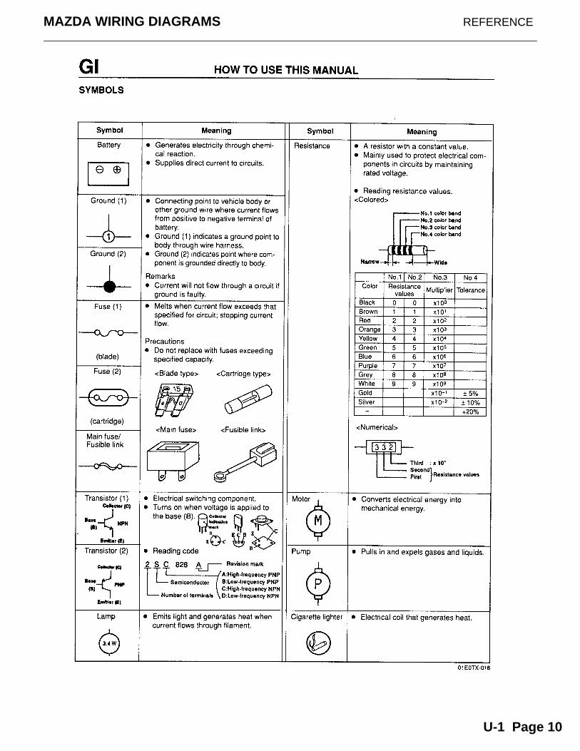
Wiring Diagrams1. Understanding Diagrams Page U-1
Lighting Systems1. Headlights Page L-12. Turnsignals & Hazard Page L-23. Stop Lights Page L-34. Backup / Horn Page L-4
Accessories Systems1. Power Windows Page A-12. Power Mirrors Page A-23. Door Locks Page A-3 4. Clock & Cig Lighter Page A-4 5. Front Wiper & Washer Page A-5 6. Blower Page A-6
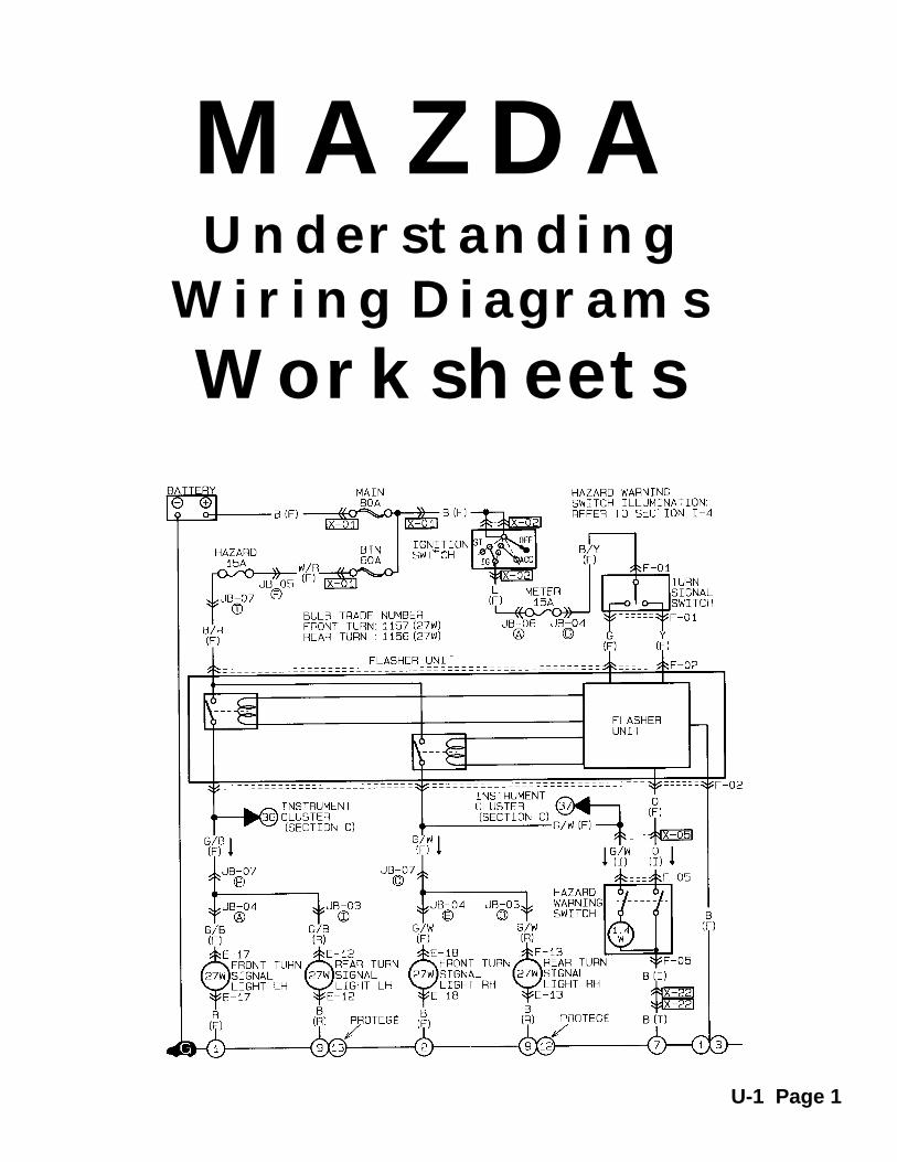
MAZDAUnderstanding
Wiring Diagrams
Worksheets
U-1 Page 1
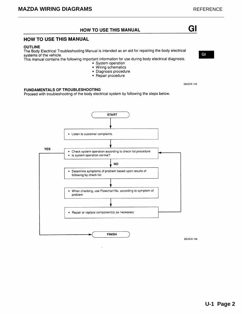
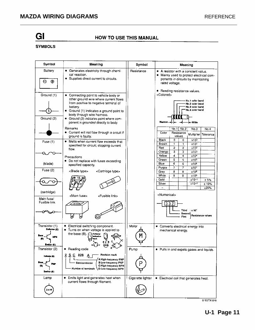
MAZDA WIRING DIAGRAMS REFERENCE
U-1 Page 2
MAZDA WIRING DIAGRAMS REFERENCE
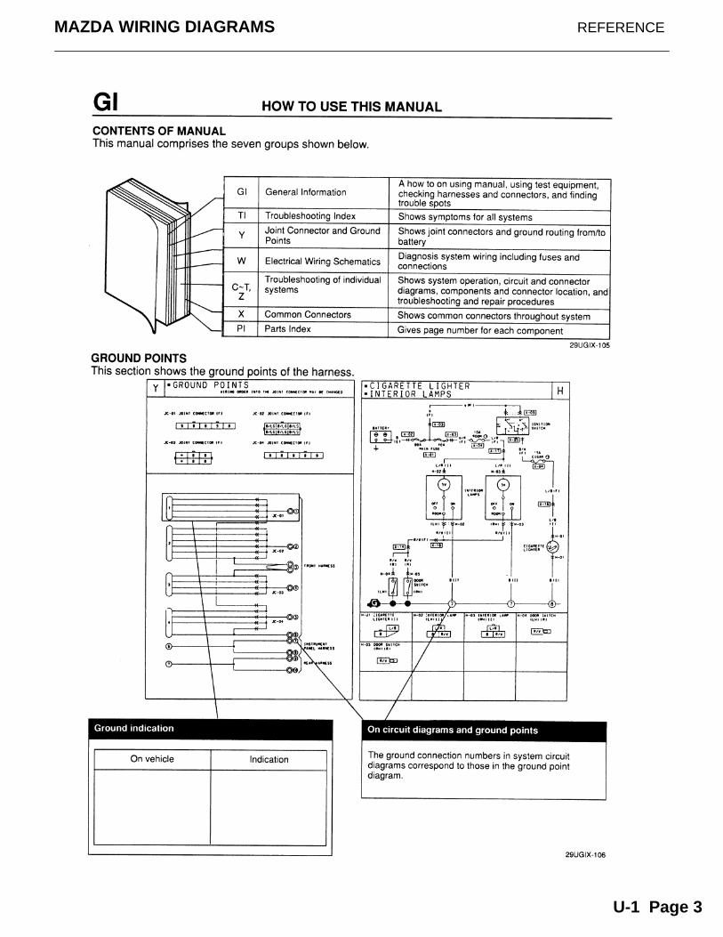
U-1 Page 3
MAZDA WIRING DIAGRAMS REFERENCE
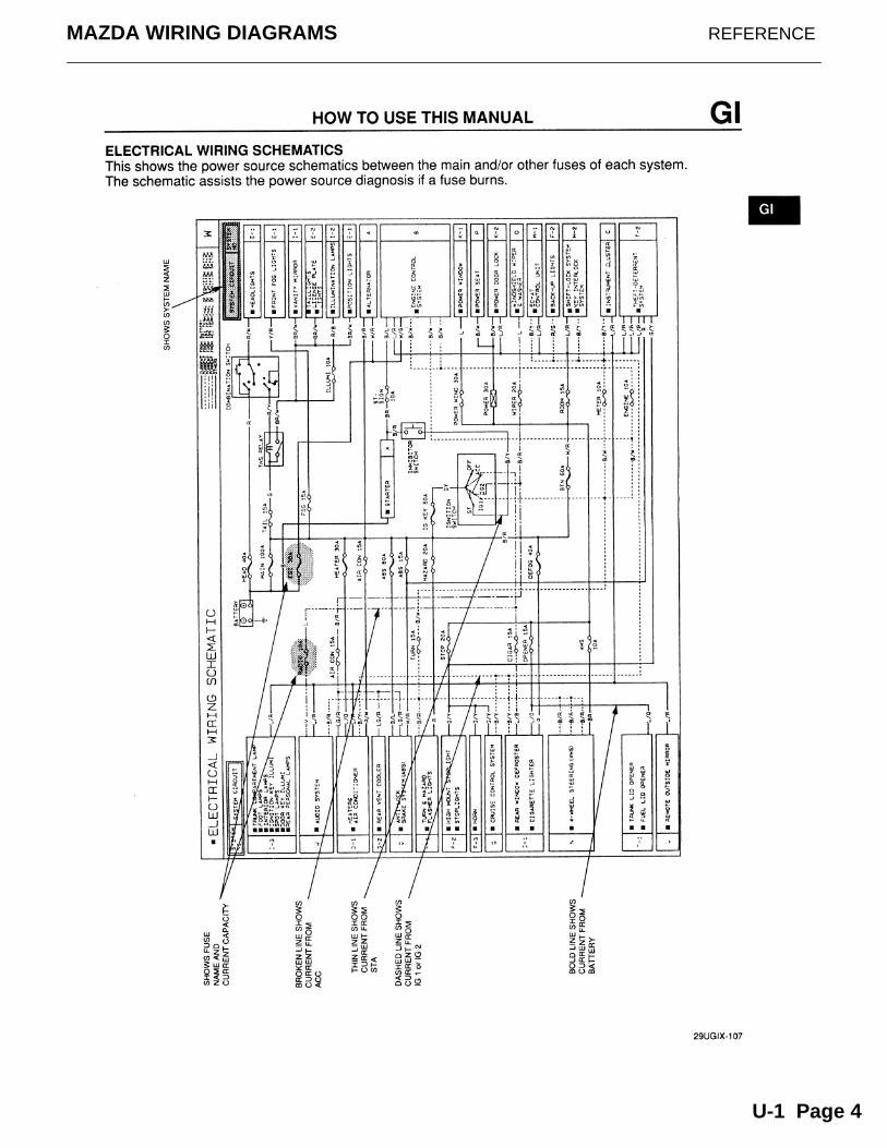
U-1 Page 4
MAZDA WIRING DIAGRAMS REFERENCE
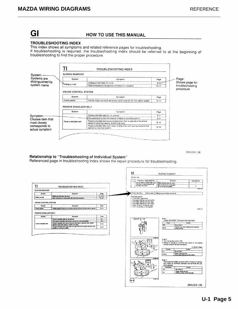
U-1 Page 5
MAZDA WIRING DIAGRAMS REFERENCE
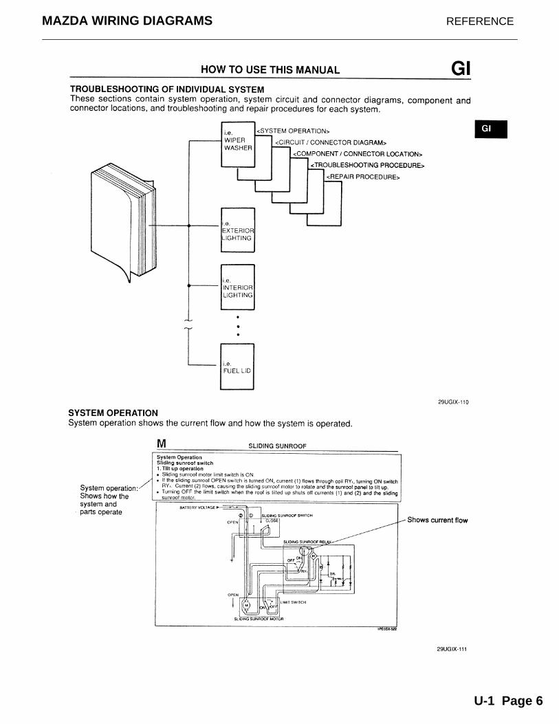
U-1 Page 6
MAZDA WIRING DIAGRAMS REFERENCE
U-1 Page 7
MAZDA WIRING DIAGRAMS REFERENCE
U-1 Page 8
MAZDA WIRING DIAGRAMS REFERENCE
U-1 Page 9
MAZDA WIRING DIAGRAMS REFERENCE
U-1 Page 10
MAZDA WIRING DIAGRAMS REFERENCE
U-1 Page 11
MAZDA WIRING DIAGRAMS WORKSHEET #1
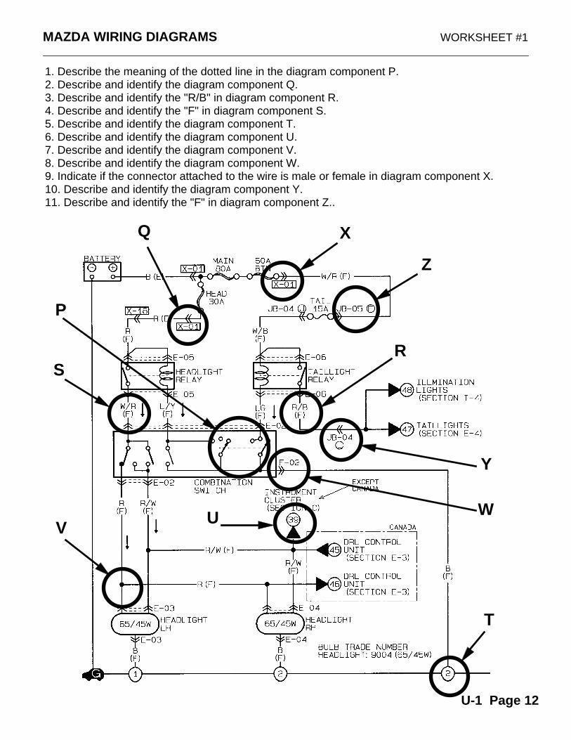
1. Describe the meaning of the dotted line in the diagram component P.2. Describe and identify the diagram component Q.3. Describe and identify the "R/B" in diagram component R.4. Describe and identify the "F" in diagram component S.5. Describe and identify the diagram component T.6. Describe and identify the diagram component U.7. Describe and identify the diagram component V.8. Describe and identify the diagram component W.9. Indicate if the connector attached to the wire is male or female in diagram component X.10. Describe and identify the diagram component Y.11. Describe and identify the "F" in diagram component Z..
X
Y
Z
WV
U
T
SR
Q
P
U-1 Page 12
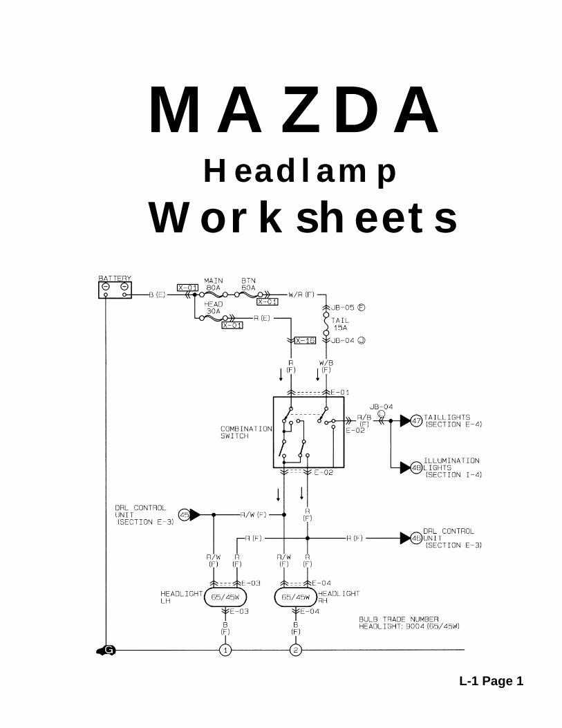
MAZDAHeadlamp
Worksheets
L-1 Page 1
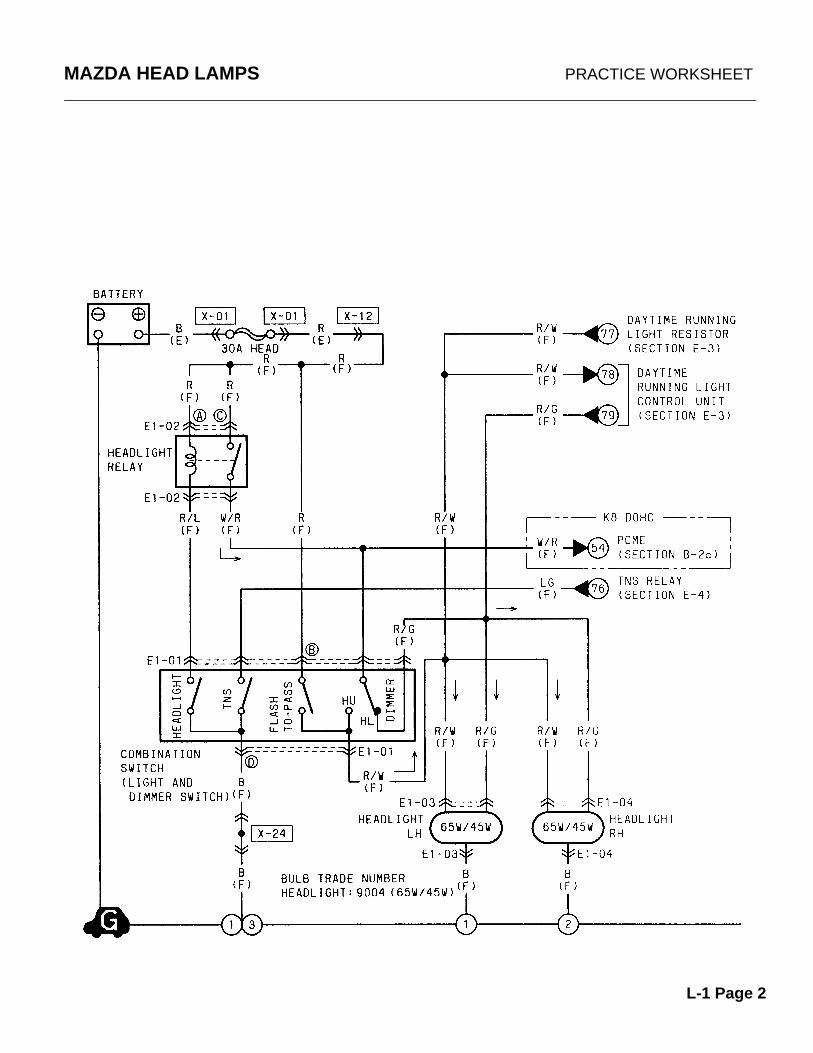
MAZDA HEAD LAMPS PRACTICE WORKSHEET
L-1 Page 2
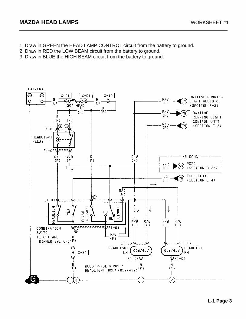
MAZDA HEAD LAMPS WORKSHEET #1
1. Draw in GREEN the HEAD LAMP CONTROL circuit from the battery to ground.2. Draw in RED the LOW BEAM circuit from the battery to ground.3. Draw in BLUE the HIGH BEAM circuit from the battery to ground.
L-1 Page 3
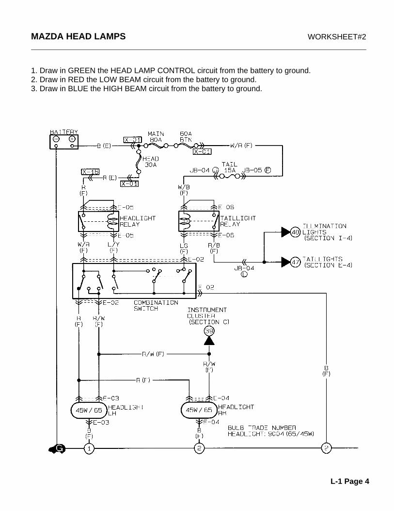
MAZDA HEAD LAMPS WORKSHEET#2
1. Draw in GREEN the HEAD LAMP CONTROL circuit from the battery to ground.2. Draw in RED the LOW BEAM circuit from the battery to ground.3. Draw in BLUE the HIGH BEAM circuit from the battery to ground.
L-1 Page 4
V
XY
W
Z
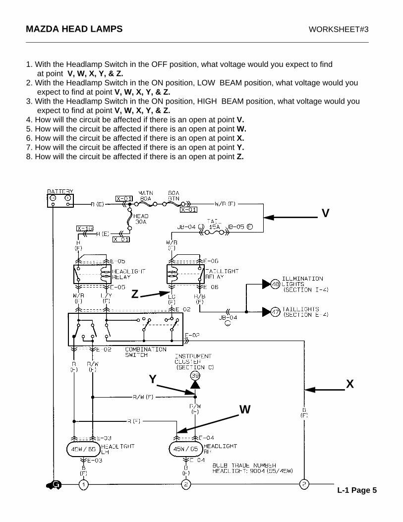
MAZDA HEAD LAMPS WORKSHEET#3
1. With the Headlamp Switch in the OFF position, what voltage would you expect to find at point V, W, X, Y, & Z.2. With the Headlamp Switch in the ON position, LOW BEAM position, what voltage would you expect to find at point V, W, X, Y, & Z.3. With the Headlamp Switch in the ON position, HIGH BEAM position, what voltage would you expect to find at point V, W, X, Y, & Z.4. How will the circuit be affected if there is an open at point V.5. How will the circuit be affected if there is an open at point W.6. How will the circuit be affected if there is an open at point X.7. How will the circuit be affected if there is an open at point Y.8. How will the circuit be affected if there is an open at point Z.
L-1 Page 5
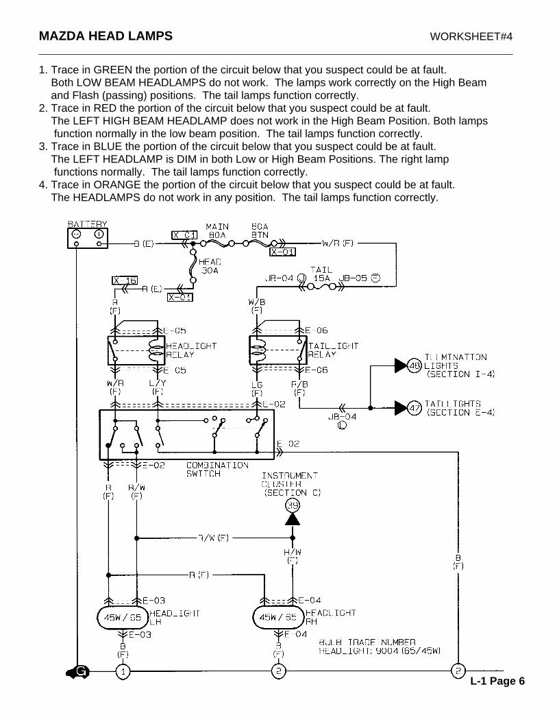
MAZDA HEAD LAMPS WORKSHEET#4
1. Trace in GREEN the portion of the circuit below that you suspect could be at fault. Both LOW BEAM HEADLAMPS do not work. The lamps work correctly on the High Beam and Flash (passing) positions. The tail lamps function correctly.2. Trace in RED the portion of the circuit below that you suspect could be at fault. The LEFT HIGH BEAM HEADLAMP does not work in the High Beam Position. Both lamps function normally in the low beam position. The tail lamps function correctly.3. Trace in BLUE the portion of the circuit below that you suspect could be at fault. The LEFT HEADLAMP is DIM in both Low or High Beam Positions. The right lamp functions normally. The tail lamps function correctly.4. Trace in ORANGE the portion of the circuit below that you suspect could be at fault. The HEADLAMPS do not work in any position. The tail lamps function correctly.
L-1 Page 6
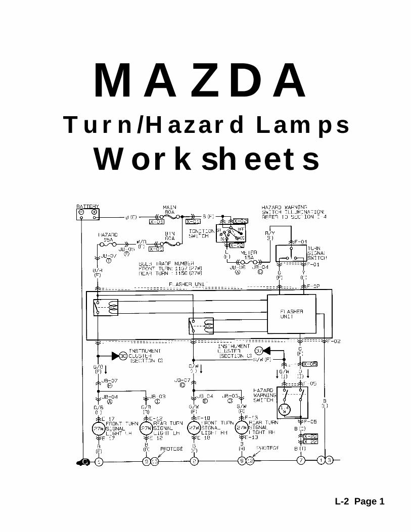
MAZDATurn/Hazard Lamps
Worksheets
L-2 Page 1
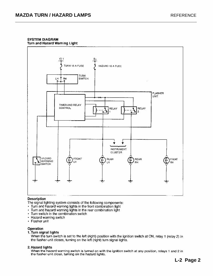
MAZDA TURN / HAZARD LAMPS REFERENCE
L-2 Page 2

MAZDA TURN / HAZARD LAMPS PRACTICE WORKSHEET #1
L-2 Page 3
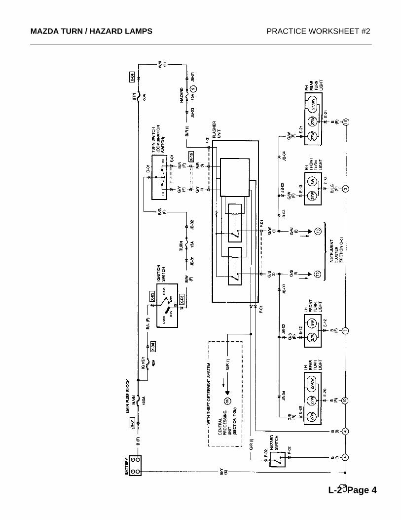
MAZDA TURN / HAZARD LAMPS PRACTICE WORKSHEET #2
L-2 Page 4
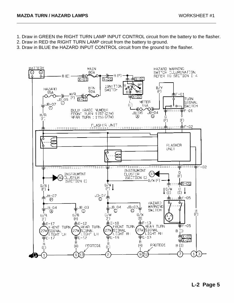
MAZDA TURN / HAZARD LAMPS WORKSHEET #1
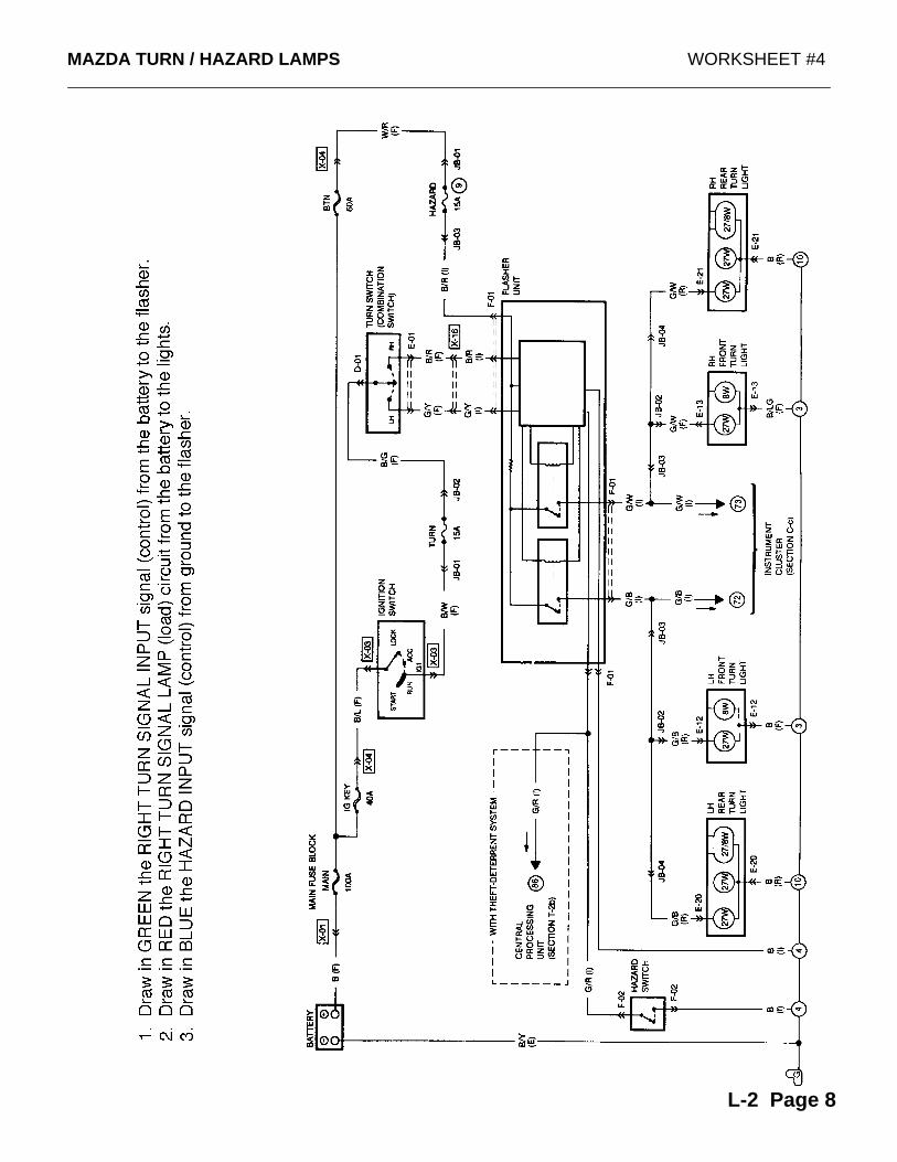
1. Draw in GREEN the RIGHT TURN LAMP INPUT CONTROL circuit from the battery to the flasher.2. Draw in RED the RIGHT TURN LAMP circuit from the battery to ground.3. Draw in BLUE the HAZARD INPUT CONTROL circuit from the ground to the flasher.
L-2 Page 5
MAZDA TURN / HAZARD LAMPS WORKSHEET #2
Y
V
U Z
W
X
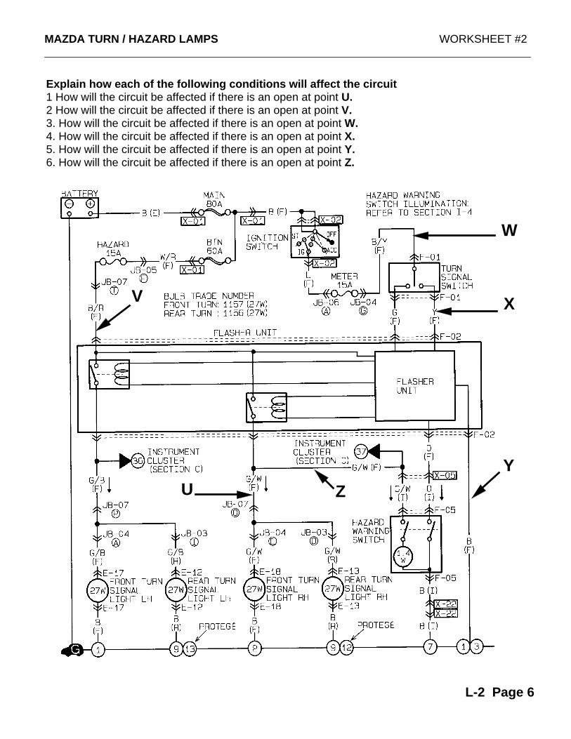
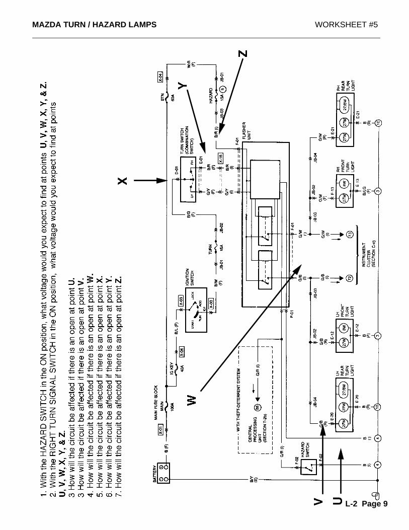
Explain how each of the following conditions will affect the circuit1 How will the circuit be affected if there is an open at point U.2 How will the circuit be affected if there is an open at point V.3. How will the circuit be affected if there is an open at point W.4. How will the circuit be affected if there is an open at point X.5. How will the circuit be affected if there is an open at point Y.6. How will the circuit be affected if there is an open at point Z.
L-2 Page 6
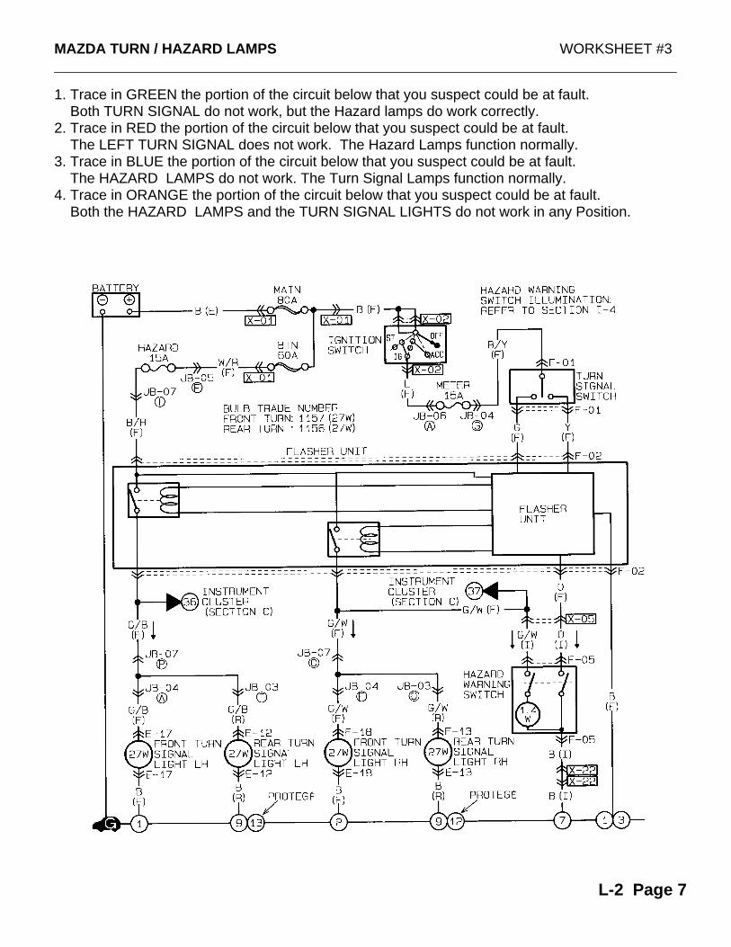
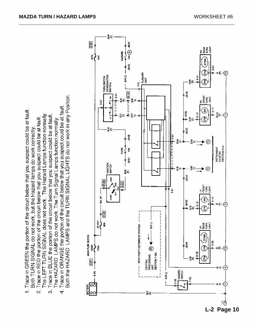
1. Trace in GREEN the portion of the circuit below that you suspect could be at fault. Both TURN SIGNAL do not work, but the Hazard lamps do work correctly.2. Trace in RED the portion of the circuit below that you suspect could be at fault. The LEFT TURN SIGNAL does not work. The Hazard Lamps function normally.3. Trace in BLUE the portion of the circuit below that you suspect could be at fault. The HAZARD LAMPS do not work. The Turn Signal Lamps function normally.4. Trace in ORANGE the portion of the circuit below that you suspect could be at fault. Both the HAZARD LAMPS and the TURN SIGNAL LIGHTS do not work in any Position.
MAZDA TURN / HAZARD LAMPS WORKSHEET #3
L-2 Page 7
MAZDA TURN / HAZARD LAMPS WORKSHEET #4
L-2 Page 8
MAZDA TURN / HAZARD LAMPS WORKSHEET #5
L-2 Page 9
MAZDA TURN / HAZARD LAMPS WORKSHEET #6
L-2 Page 10

MAZDAStoplamps
Worksheets
L-3 Page 1
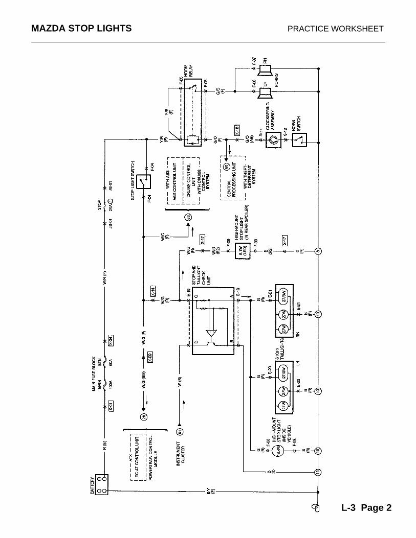
MAZDA STOP LIGHTS PRACTICE WORKSHEET
L-3 Page 2
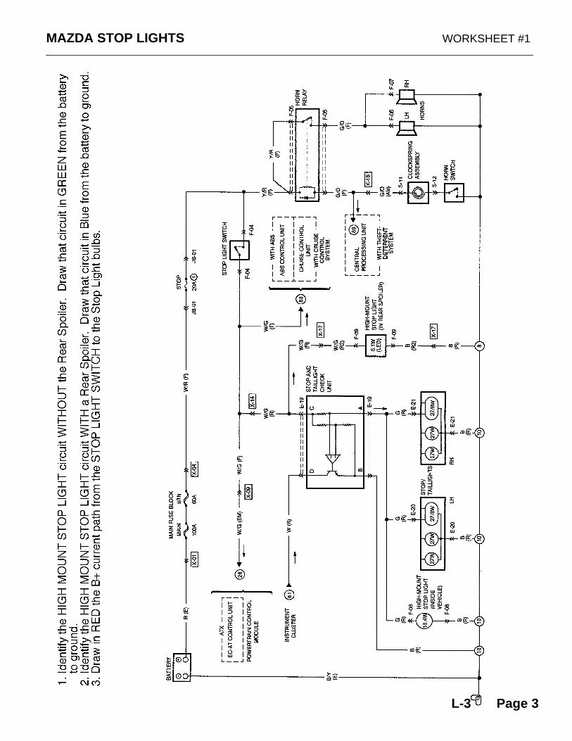
MAZDA STOP LIGHTS WORKSHEET #1
L-3 Page 3
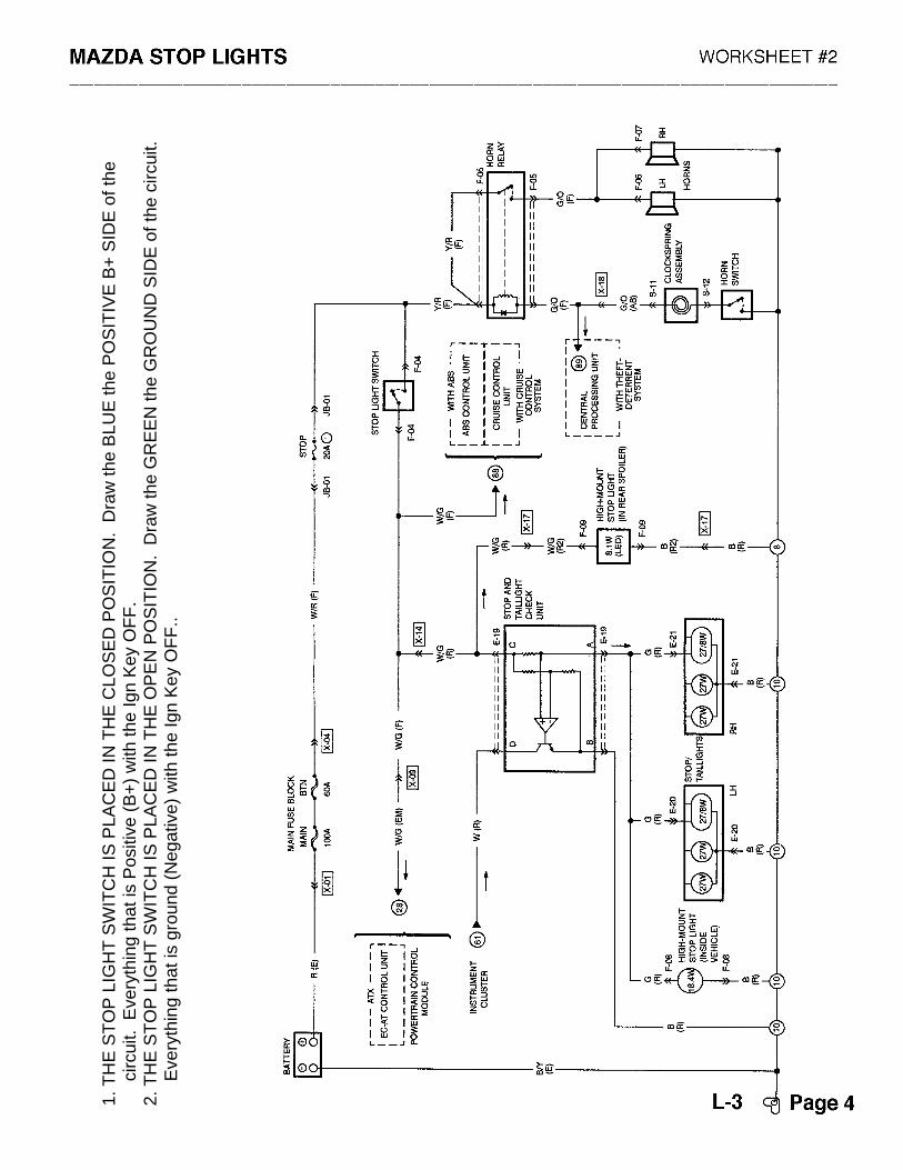
1. T
HE
ST
OP
LIG
HT
SW
ITC
H IS
PLA
CE
D IN
TH
E C
LOS
ED
PO
SIT
ION
. D
raw
the
BLU
E th
e P
OS
ITIV
E B
+ S
IDE
of t
he
c
ircui
t. E
very
thin
g th
at is
Pos
itive
(B
+)
with
the
Ign
Key
OF
F.
2. T
HE
ST
OP
LIG
HT
SW
ITC
H IS
PLA
CE
D IN
TH
E O
PE
N P
OS
ITIO
N.
Dra
w th
e G
RE
EN
the
GR
OU
ND
SID
E o
f the
circ
uit.
Eve
ryth
ing
that
is g
roun
d (N
egat
ive)
with
the
Ign
Key
OF
F..
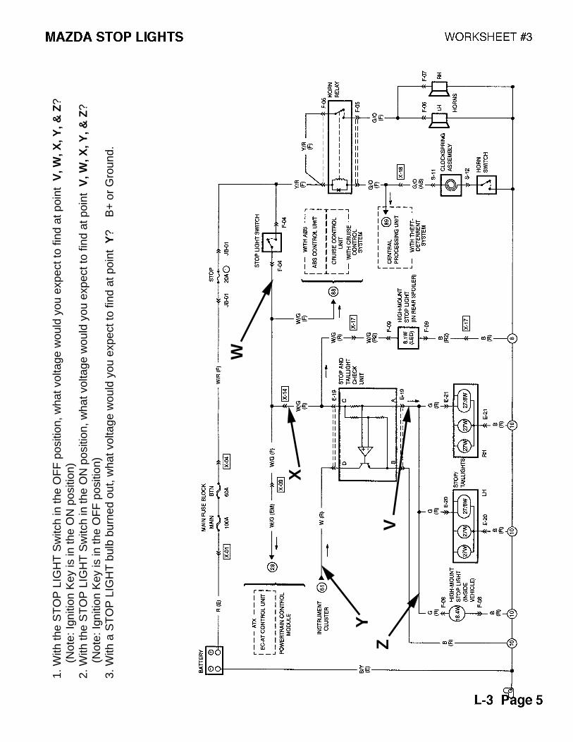
1. W
ith th
e S
TO
P L
IGH
T S
witc
h in
the
OF
F p
ositi
on, w
hat v
olta
ge w
ould
you
exp
ect t
o fin
d at
poi
nt V
, W, X
, Y, &
Z?
(
Not
e: Ig
nitio
n K
ey is
in th
e O
N p
ositi
on)
2. W
ith th
e S
TO
P L
IGH
T S
witc
h in
the
ON
pos
ition
, wha
t vol
tage
wou
ld y
ou e
xpec
t to
find
at p
oint
V, W
, X, Y
, & Z
?
(
Not
e: Ig
nitio
n K
ey is
in th
e O
FF
pos
ition
)3.
With
a S
TO
P L
IGH
T b
ulb
burn
ed o
ut, w
hat v
olta
ge w
ould
you
exp
ect t
o fin
d at
poi
nt Y
?
B+
or
Gro
und.
ZV
W
X
Y
ZV
W
X
Y
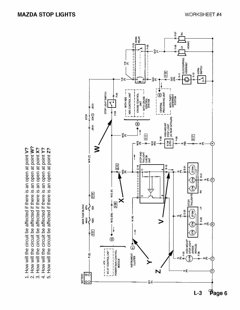
1. H
ow w
ill th
e ci
rcui
t be
affe
cted
if th
ere
is a
n op
en a
t poi
nt V
?2.
How
will
the
circ
uit b
e af
fect
ed if
ther
e is
an
open
at p
oint
W?
3. H
ow w
ill th
e ci
rcui
t be
affe
cted
if th
ere
is a
n op
en a
t poi
nt X
?4.
How
will
the
circ
uit b
e af
fect
ed if
ther
e is
an
open
at p
oint
Y?
5. H
ow w
ill th
e ci
rcui
t be
affe
cted
if th
ere
is a
n op
en a
t poi
nt Z
?
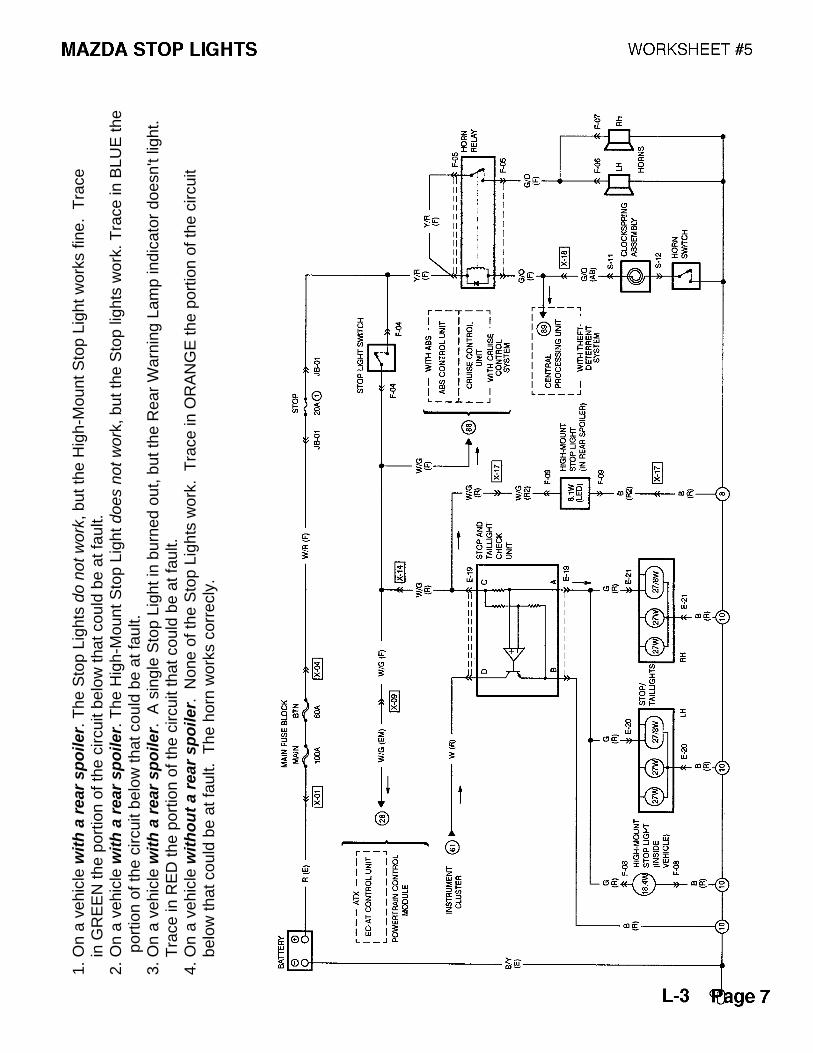
1. O
n a
vehi
cle
wit
h a
rear
sp
oiler.
The
Sto
p Li
ghts
do n
ot w
ork
, but
the
Hig
h-M
ount
Sto
p Li
ght w
orks
fine
. T
race
in G
RE
EN
the
port
ion
of th
e ci
rcui
t bel
ow th
at c
ould
be
at fa
ult.
2. O
n a
vehi
cle
wit
h a
rear
sp
oiler.
The
Hig
h-M
ount
Sto
p Li
ght d
oes
not w
ork
, but
the
Sto
p lig
hts
wor
k. T
race
in B
LUE
the
p
ortio
n of
the
circ
uit b
elow
that
cou
ld b
e at
faul
t.3.
On
a ve
hicl
e w
ith
a r
ear
sp
oiler.
A s
ingl
e S
top
Ligh
t in
burn
ed o
ut, b
ut th
e R
ear
War
ning
Lam
p in
dica
tor
does
n't l
ight
.
Tra
ce in
RE
D th
e po
rtio
n of
the
circ
uit t
hat c
ould
be
at fa
ult.
4. O
n a
vehi
cle
wit
ho
ut
a r
ear
sp
oiler.
Non
e of
the
Sto
p Li
ghts
wor
k. T
race
in O
RA
NG
E th
e po
rtio
n of
the
circ
uit
b
elow
that
cou
ld b
e at
faul
t. T
he h
orn
wor
ks c
orre
cly.
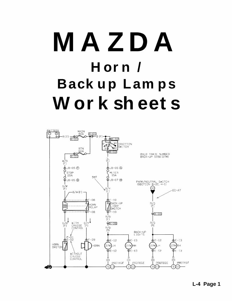
MAZDAHorn /
Backup Lamps
Worksheets
L-4 Page 1
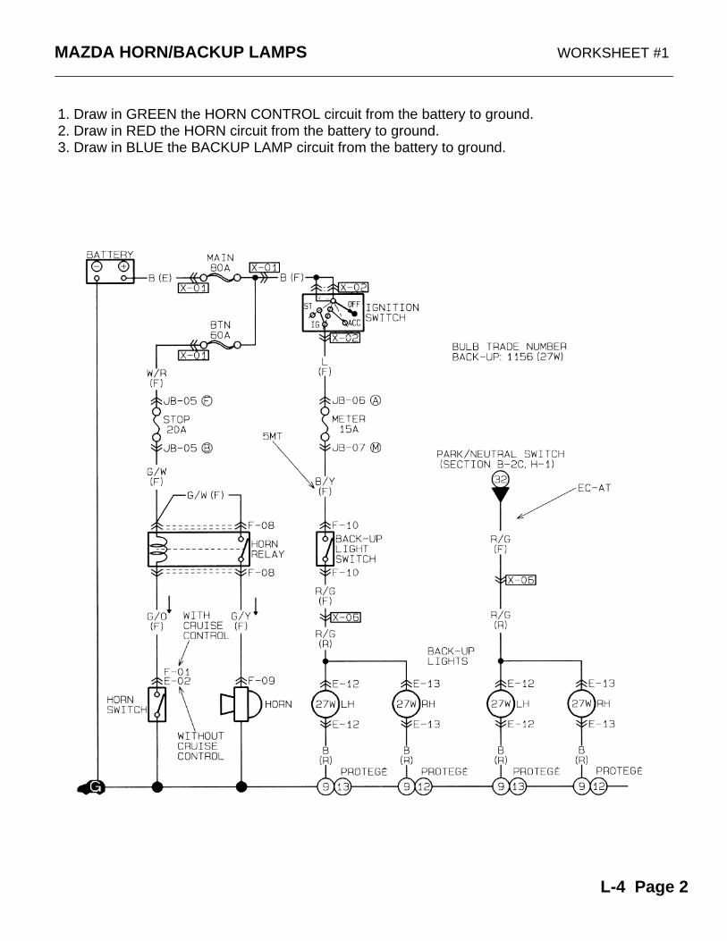
MAZDA HORN/BACKUP LAMPS WORKSHEET #1
1. Draw in GREEN the HORN CONTROL circuit from the battery to ground.2. Draw in RED the HORN circuit from the battery to ground.3. Draw in BLUE the BACKUP LAMP circuit from the battery to ground.
L-4 Page 2
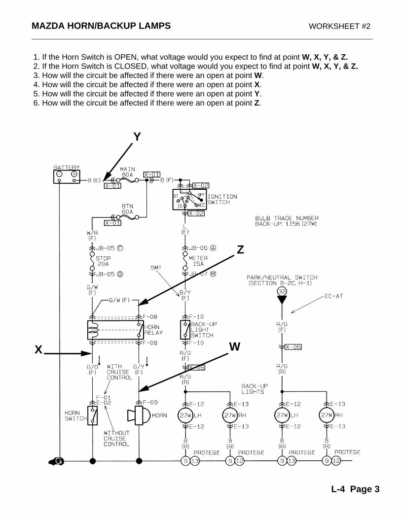
MAZDA HORN/BACKUP LAMPS WORKSHEET #2
1. If the Horn Switch is OPEN, what voltage would you expect to find at point W, X, Y, & Z.2. If the Horn Switch is CLOSED, what voltage would you expect to find at point W, X, Y, & Z.3. How will the circuit be affected if there were an open at point W.4. How will the circuit be affected if there were an open at point X.5. How will the circuit be affected if there were an open at point Y.6. How will the circuit be affected if there were an open at point Z.
X
Z
Y
W
L-4 Page 3
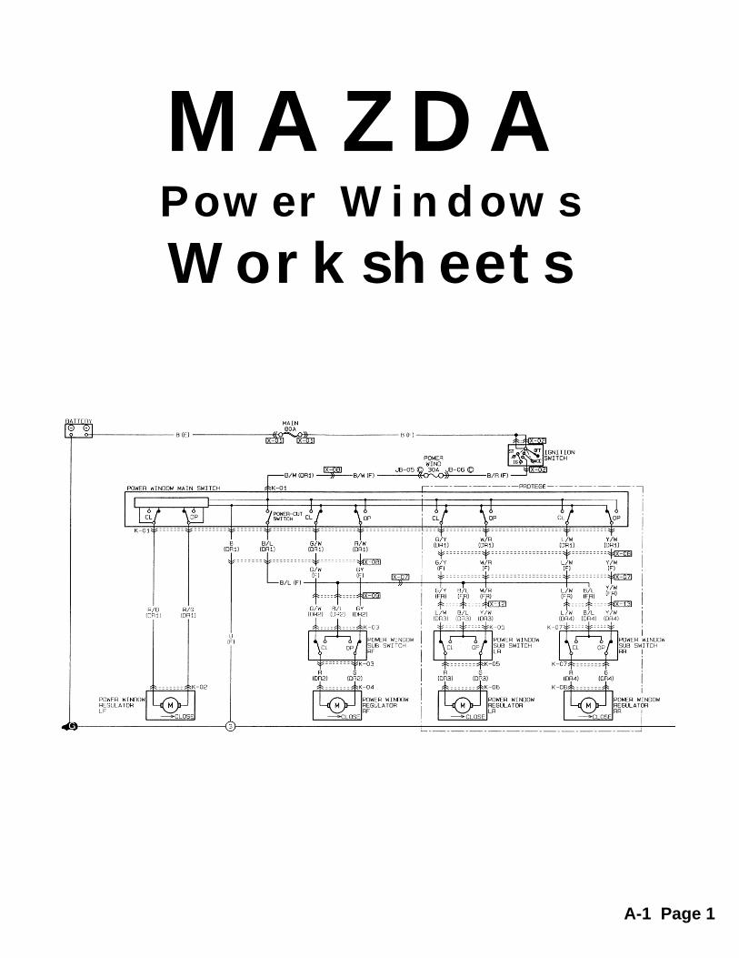
MAZDAPower Windows
Worksheets
A-1 Page 1
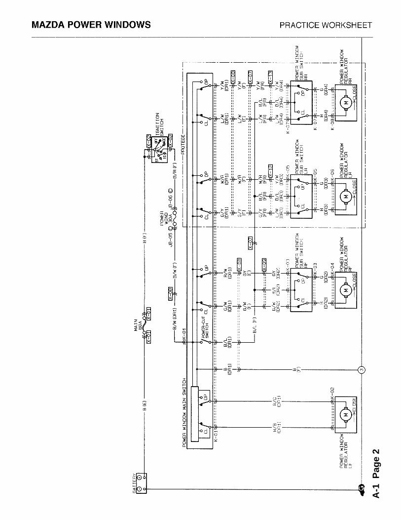
A-1
Pag
e 2
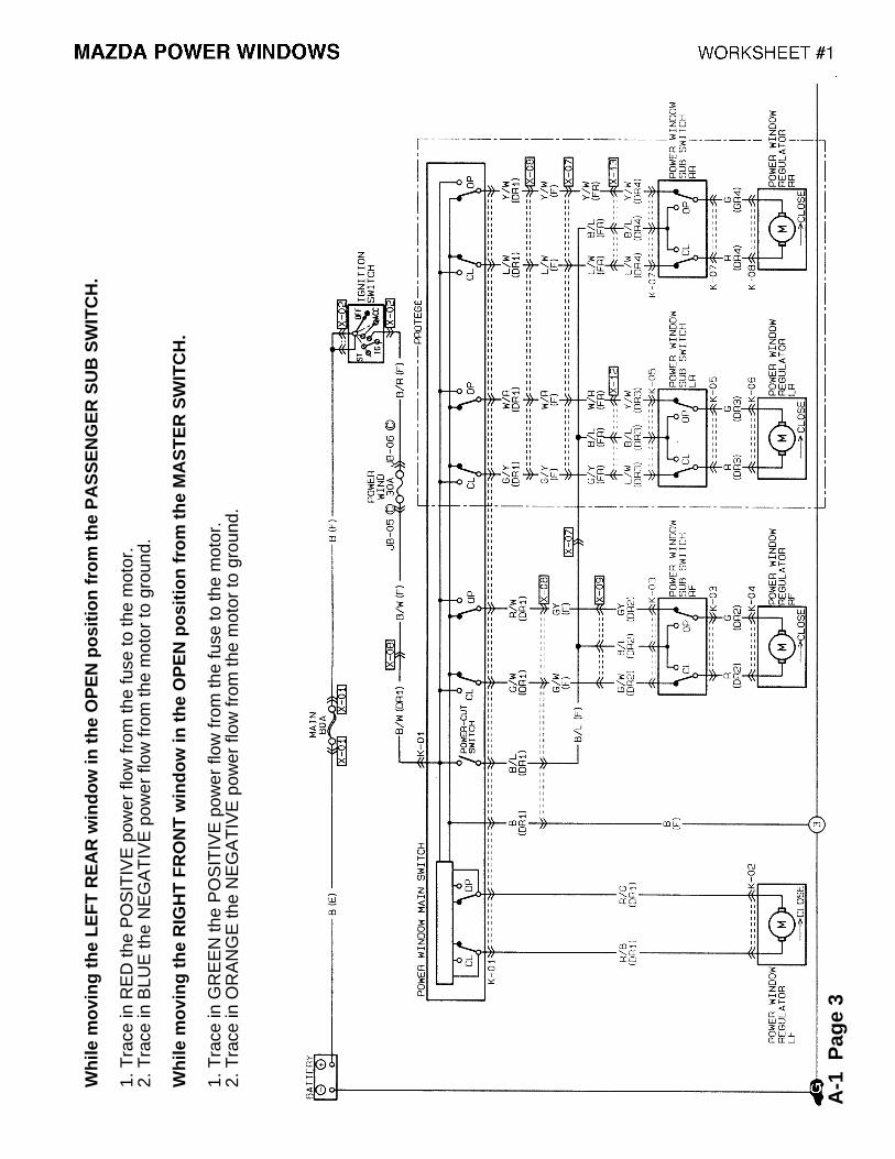
Wh
ile m
ovi
ng
th
e L
EF
T R
EA
R w
ind
ow
in t
he
OP
EN
po
siti
on
fro
m t
he
PA
SS
EN
GE
R S
UB
SW
ITC
H.
1. T
race
in R
ED
the
PO
SIT
IVE
pow
er fl
ow fr
om th
e fu
se to
the
mot
or.
2. T
race
in B
LUE
the
NE
GA
TIV
E p
ower
flow
from
the
mot
or to
gro
und.
Wh
ile m
ovi
ng
th
e R
IGH
T F
RO
NT
win
do
w in
th
e O
PE
N p
osi
tio
n f
rom
th
e M
AS
TE
R S
WIT
CH
.
1. T
race
in G
RE
EN
the
PO
SIT
IVE
pow
er fl
ow fr
om th
e fu
se to
the
mot
or.
2. T
race
in O
RA
NG
E th
e N
EG
AT
IVE
pow
er fl
ow fr
om th
e m
otor
to g
roun
d.
A-1
Pag
e 3
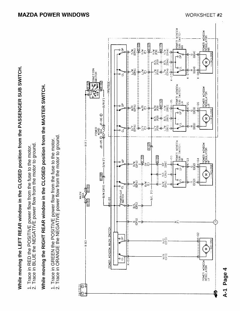
Wh
ile m
ovi
ng
th
e L
EF
T R
EA
R w
ind
ow
in t
he
CL
OS
ED
po
siti
on
fro
m t
he
PA
SS
EN
GE
R S
UB
SW
ITC
H.
1. T
race
in R
ED
the
PO
SIT
IVE
pow
er fl
ow fr
om th
e fu
se to
the
mot
or.
2. T
race
in B
LUE
the
NE
GA
TIV
E p
ower
flow
from
the
mot
or to
gro
und.
Wh
ile m
ovi
ng
th
e R
IGH
T R
EA
R w
ind
ow
in t
he
CL
OS
ED
po
siti
on
fro
m t
he
MA
ST
ER
SW
ITC
H.
1. T
race
in G
RE
EN
the
PO
SIT
IVE
pow
er fl
ow fr
om th
e fu
se to
the
mot
or.
2. T
race
in O
RA
NG
E th
e N
EG
AT
IVE
pow
er fl
ow fr
om th
e m
otor
to g
roun
d.
A-1
Pag
e 4

Wh
ile m
ovi
ng
th
e R
IGH
T R
EA
R w
ind
ow
in t
he
CL
OS
ED
po
siti
on
fro
m t
he
PA
SS
EN
GE
R S
UB
SW
ITC
H.
1. T
race
in R
ED
the
PO
SIT
IVE
pow
er fl
ow fr
om th
e fu
se to
the
mot
or.
2. T
race
in B
LUE
the
NE
GA
TIV
E p
ower
flow
from
the
mot
or to
gro
und.
Wh
ile m
ovi
ng
th
e L
EF
T R
EA
R w
ind
ow
in t
he
CL
OS
ED
po
siti
on
fro
m t
he
MA
ST
ER
SW
ITC
H.
1. T
race
in G
RE
EN
the
PO
SIT
IVE
pow
er fl
ow fr
om th
e fu
se to
the
mot
or.
2. T
race
in O
RA
NG
E th
e N
EG
AT
IVE
pow
er fl
ow fr
om th
e m
otor
to g
roun
d.
A-1
Pag
e 5
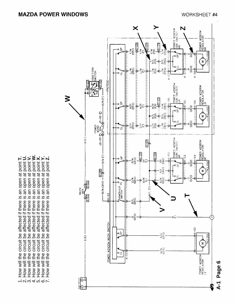
1. H
ow w
ill th
e ci
rcui
t be
affe
cted
if th
ere
is a
n op
en a
t poi
nt T
.2.
How
will
the
circ
uit b
e af
fect
ed if
ther
e is
an
open
at p
oint
U.
3. H
ow w
ill th
e ci
rcui
t be
affe
cted
if th
ere
is a
n op
en a
t poi
nt V
.4.
How
will
the
circ
uit b
e af
fect
ed if
ther
e is
an
open
at p
oint
W.
5. H
ow w
ill th
e ci
rcui
t be
affe
cted
if th
ere
is a
n op
en a
t poi
nt X
.6.
How
will
the
circ
uit b
e af
fect
ed if
ther
e is
an
open
at p
oint
Y.
7. H
ow w
ill th
e ci
rcui
t be
affe
cted
if th
ere
is a
n op
en a
t poi
nt Z
.
U
YX
V
T
A-1
Pag
e 6
W
Z
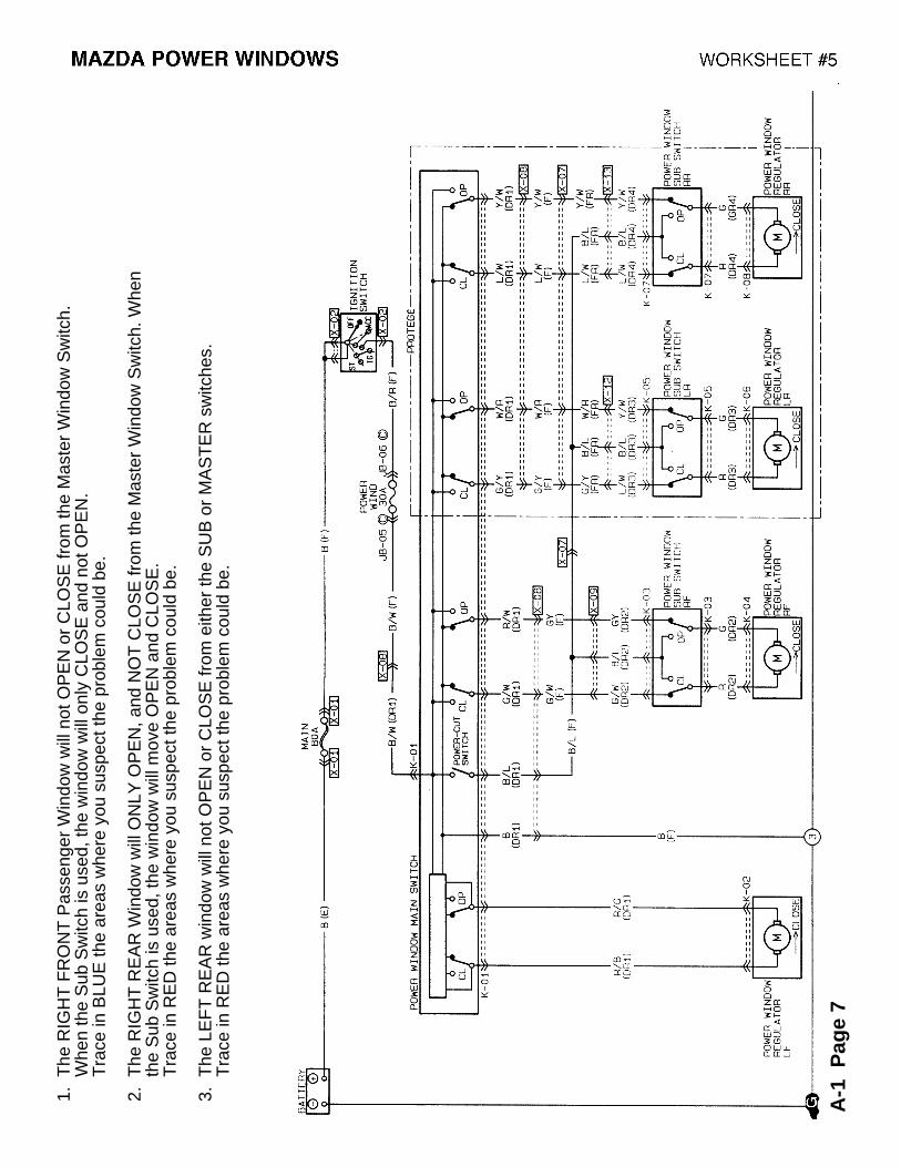
1. T
he R
IGH
T F
RO
NT
Pas
seng
er W
indo
w w
ill n
ot O
PE
N o
r C
LOS
E fr
om th
e M
aste
r W
indo
w S
witc
h.
W
hen
the
Sub
Sw
itch
is u
sed,
the
win
dow
will
onl
y C
LOS
E a
nd n
ot O
PE
N.
T
race
in B
LUE
the
area
s w
here
you
sus
pect
the
prob
lem
cou
ld b
e.
2. T
he R
IGH
T R
EA
R W
indo
w w
ill O
NLY
OP
EN
, and
NO
T C
LOS
E fr
om th
e M
aste
r W
indo
w S
witc
h. W
hen
t
he S
ub S
witc
h is
use
d, th
e w
indo
w w
ill m
ove
OP
EN
and
CLO
SE
.
Tra
ce in
RE
D th
e ar
eas
whe
re y
ou s
uspe
ct th
e pr
oble
m c
ould
be.
3. T
he L
EF
T R
EA
R w
indo
w w
ill n
ot O
PE
N o
r C
LOS
E fr
om e
ither
the
SU
B o
r M
AS
TE
R s
witc
hes.
T
race
in R
ED
the
area
s w
here
you
sus
pect
the
prob
lem
cou
ld b
e.
A-1
Pag
e 7
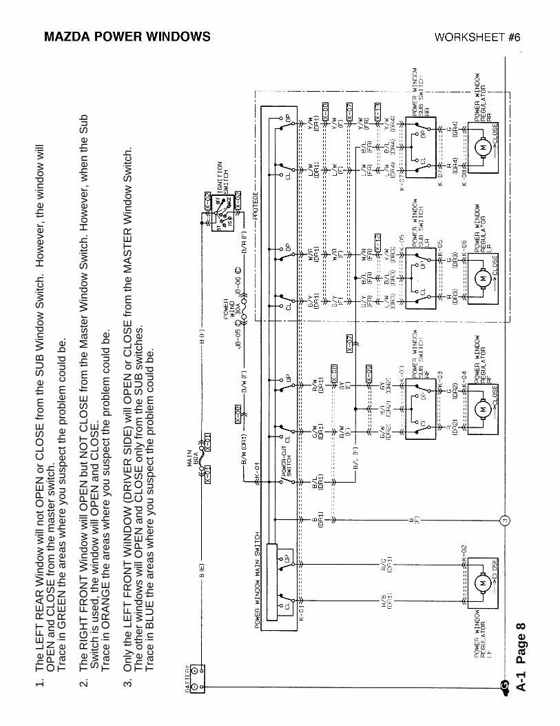
1. T
he L
EF
T R
EA
R W
indo
w w
ill n
ot O
PE
N o
r C
LOS
E fr
om th
e S
UB
Win
dow
Sw
itch.
How
ever
, the
win
dow
will
OP
EN
and
CLO
SE
from
the
mas
ter
switc
h.
Tra
ce in
GR
EE
N th
e ar
eas
whe
re y
ou s
uspe
ct th
e pr
oble
m c
ould
be.
2. T
he R
IGH
T F
RO
NT
Win
dow
will
OP
EN
but
NO
T C
LOS
E fr
om th
e M
aste
r W
indo
w S
witc
h. H
owev
er, w
hen
the
Sub
S
witc
h is
use
d, th
e w
indo
w w
ill O
PE
N a
nd C
LOS
E.
T
race
in O
RA
NG
E th
e ar
eas
whe
re y
ou s
uspe
ct th
e pr
oble
m c
ould
be.
3. O
nly
the
LEF
T F
RO
NT
WiIN
DO
W (
DR
IVE
R S
IDE
) w
ill O
PE
N o
r C
LOS
E fr
om th
e M
AS
TE
R W
indo
w S
witc
h.
T
he o
ther
win
dow
s w
ill O
PE
N a
nd C
LOS
E o
nly
from
the
SU
B s
witc
hes.
T
race
in B
LUE
the
area
s w
here
you
sus
pect
the
prob
lem
cou
ld b
e.
A-1
Pag
e 8
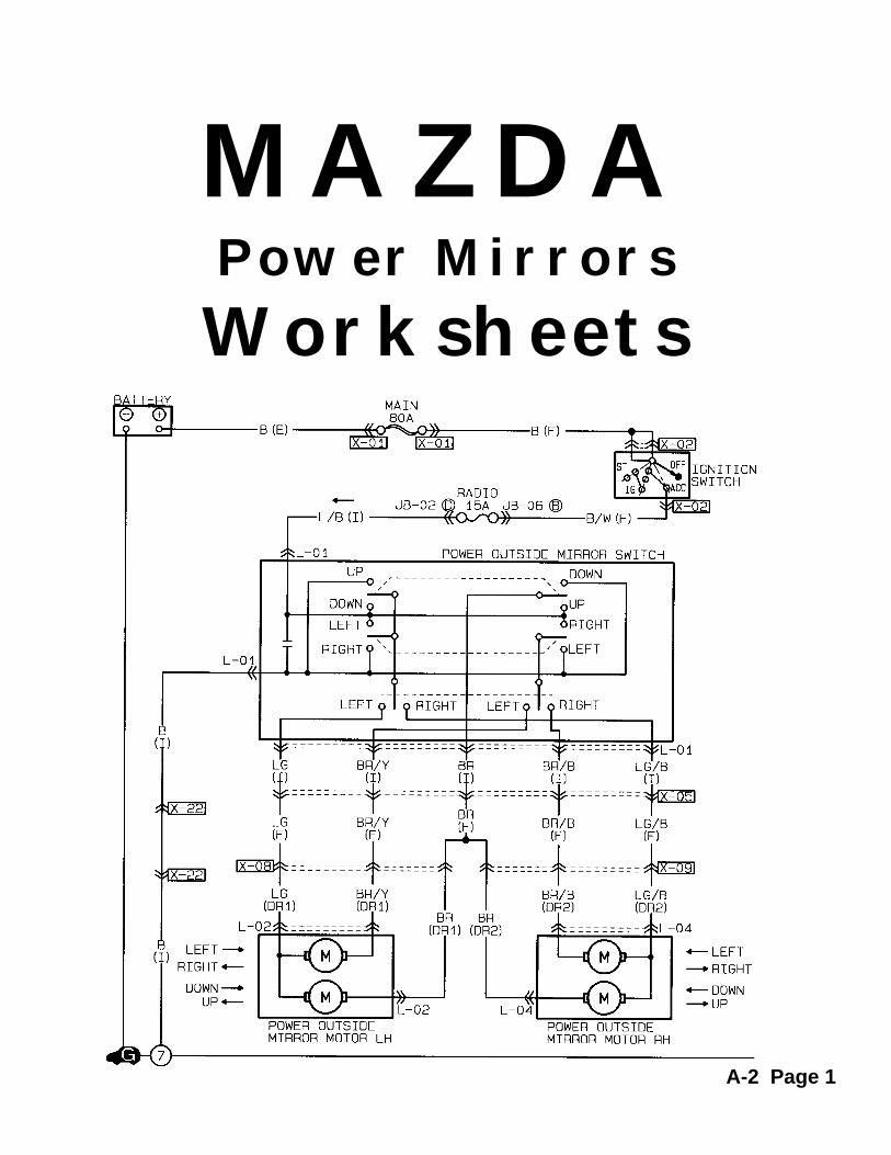
MAZDAPower Mirrors
Worksheets
A-2 Page 1
MAZDA POWER MIRRORS PRACTICE WORKSHEET
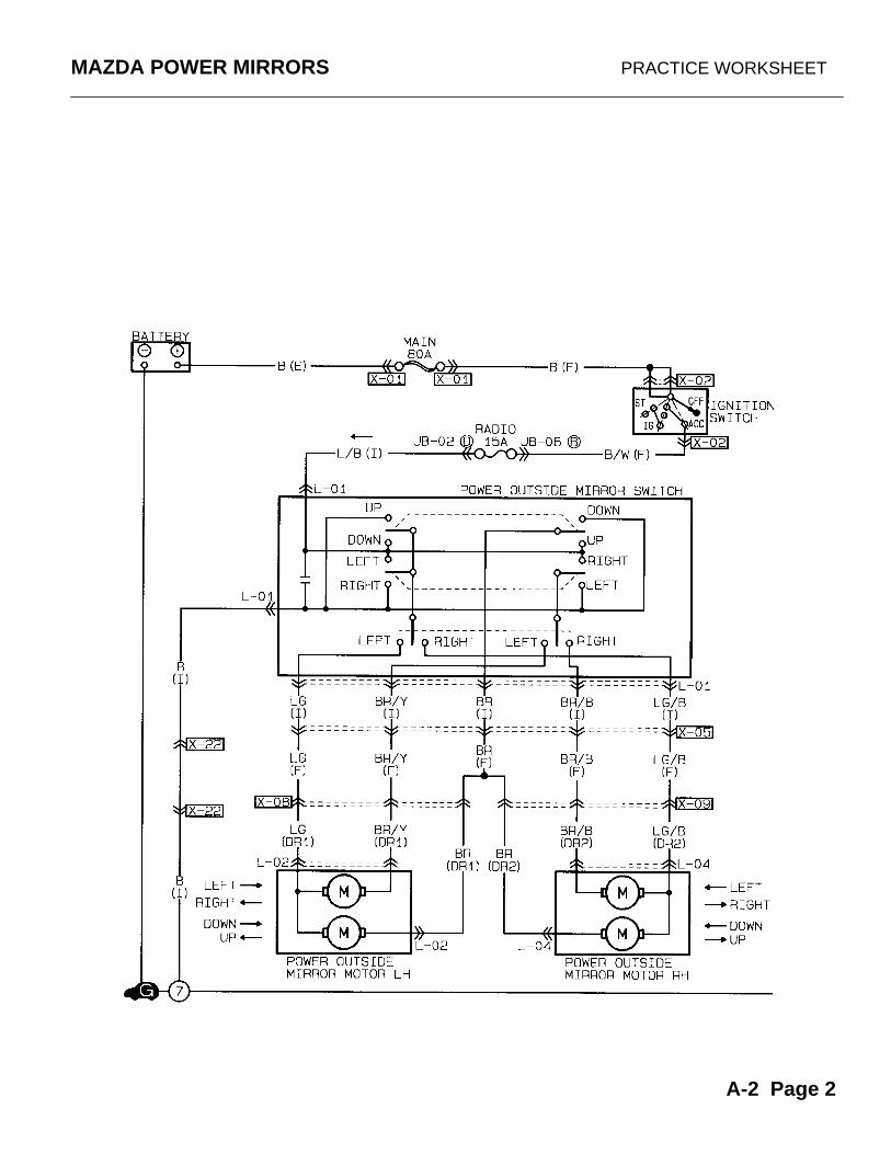
A-2 Page 2
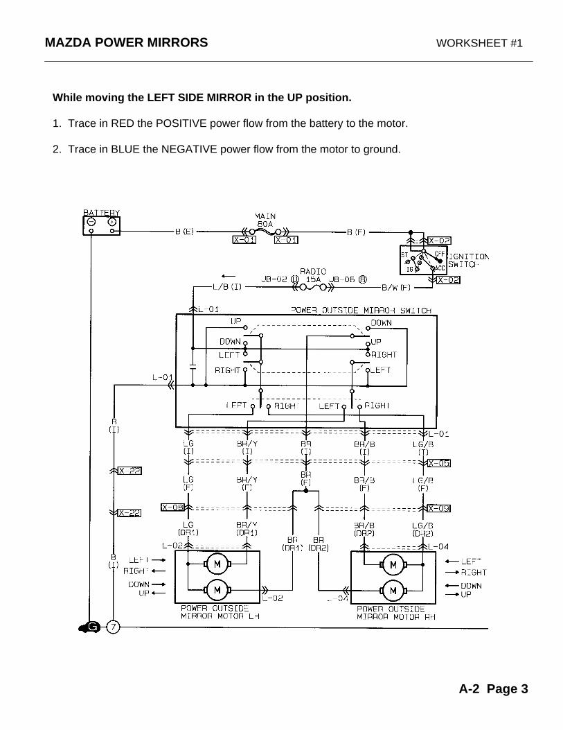
MAZDA POWER MIRRORS WORKSHEET #1
While moving the LEFT SIDE MIRROR in the UP position.
1. Trace in RED the POSITIVE power flow from the battery to the motor.
2. Trace in BLUE the NEGATIVE power flow from the motor to ground.
A-2 Page 3

MAZDA POWER MIRRORS WORKSHEET #2
While moving the RIGHT SIDE MIRROR to the RIGHT.
1. Trace in RED the POSITIVE power flow from the battery to the motor.
2. Trace in BLUE the NEGATIVE powerflow from the motor to ground.
A-2 Page 4

MAZDA POWER MIRRORS WORKSHEET #3
1. While moving the LEFT SIDE MIRROR to the LEFT. Trace in RED the current flow from the battery to ground.
2. While moving the LEFT SIDE MIRROR to the DOWN. Trace in Blue the current flow from the battery to ground.
A-2 Page 5
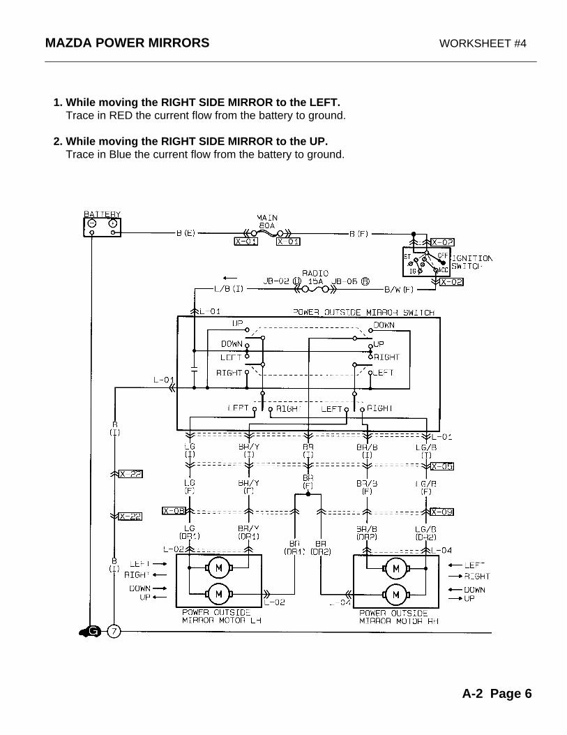
MAZDA POWER MIRRORS WORKSHEET #4
1. While moving the RIGHT SIDE MIRROR to the LEFT. Trace in RED the current flow from the battery to ground.
2. While moving the RIGHT SIDE MIRROR to the UP. Trace in Blue the current flow from the battery to ground.
A-2 Page 6
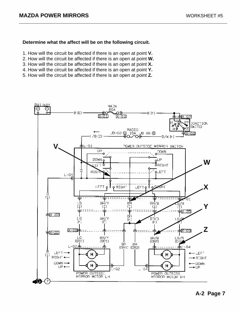
MAZDA POWER MIRRORS WORKSHEET #5
Determine what the affect will be on the following circuit.
1. How will the circuit be affected if there is an open at point V.2. How will the circuit be affected if there is an open at point W.3. How will the circuit be affected if there is an open at point X.4. How will the circuit be affected if there is an open at point Y.5. How will the circuit be affected if there is an open at point Z.
V
W
X
Y
Z
A-2 Page 7
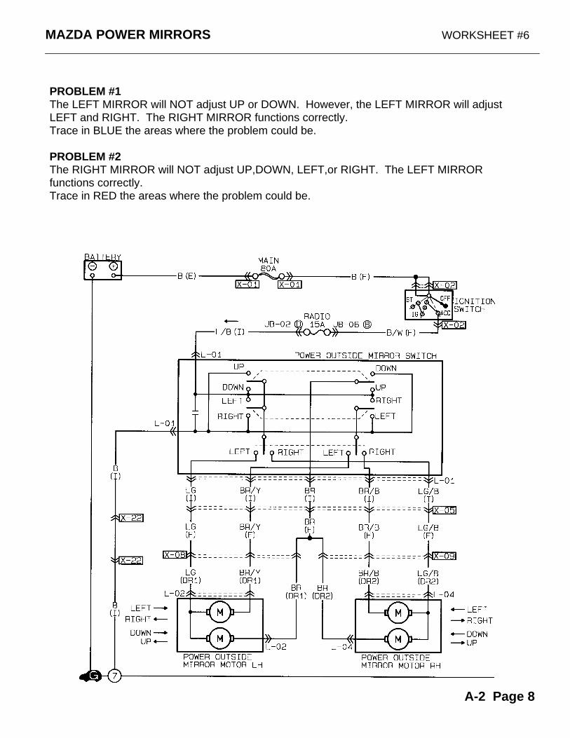
MAZDA POWER MIRRORS WORKSHEET #6
PROBLEM #1The LEFT MIRROR will NOT adjust UP or DOWN. However, the LEFT MIRROR will adjust LEFT and RIGHT. The RIGHT MIRROR functions correctly.Trace in BLUE the areas where the problem could be.
PROBLEM #2The RIGHT MIRROR will NOT adjust UP,DOWN, LEFT,or RIGHT. The LEFT MIRROR functions correctly.Trace in RED the areas where the problem could be.
A-2 Page 8
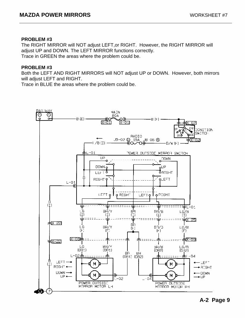
MAZDA POWER MIRRORS WORKSHEET #7
PROBLEM #3The RIGHT MIRROR will NOT adjust LEFT,or RIGHT. However, the RIGHT MIRROR will adjust UP and DOWN. The LEFT MIRROR functions correctly.Trace in GREEN the areas where the problem could be.
PROBLEM #3Both the LEFT AND RIGHT MIRRORS will NOT adjust UP or DOWN. However, both mirrors will adjust LEFT and RIGHT. Trace in BLUE the areas where the problem could be.
A-2 Page 9
MAZDADoor Lock
Worksheets
A-3 Page 1
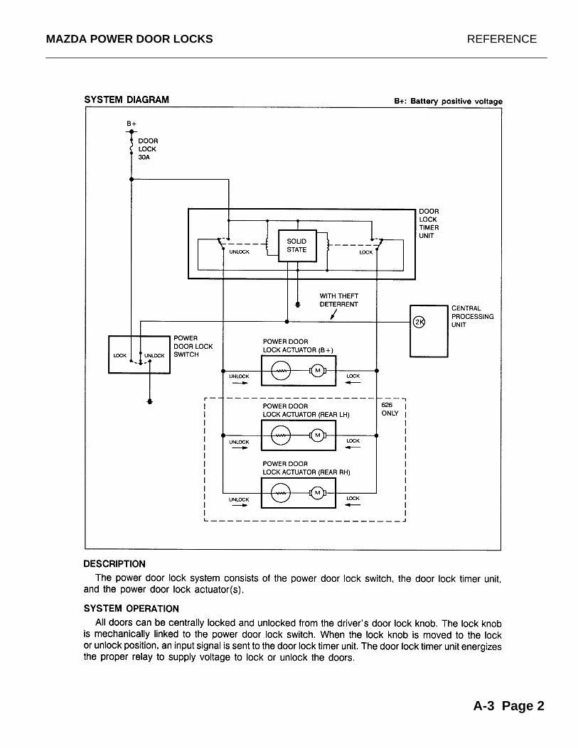
MAZDA POWER DOOR LOCKS REFERENCE
A-3 Page 2
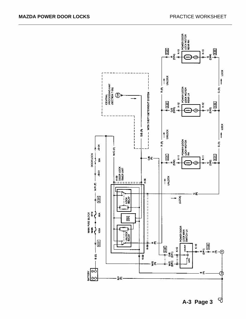
MAZDA POWER DOOR LOCKS PRACTICE WORKSHEET
A-3 Page 3
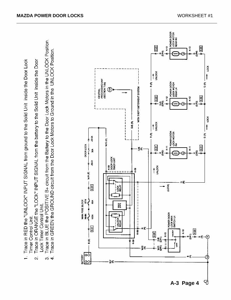
MAZDA POWER DOOR LOCKS WORKSHEET #1
A-3 Page 4
MAZDA POWER DOOR LOCKS WORKSHEET #2
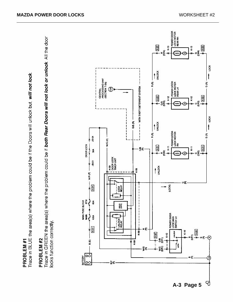
A-3 Page 5
MAZDA POWER DOOR LOCKS WORKSHEET #3
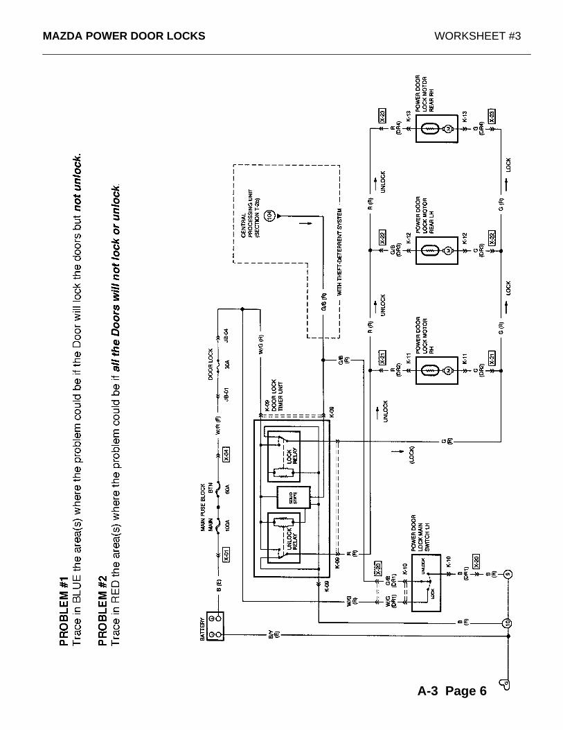
A-3 Page 6
MAZDA POWER DOOR LOCKS WORKSHEET #4
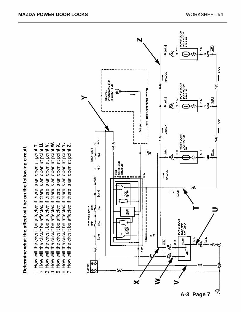
A-3 Page 7
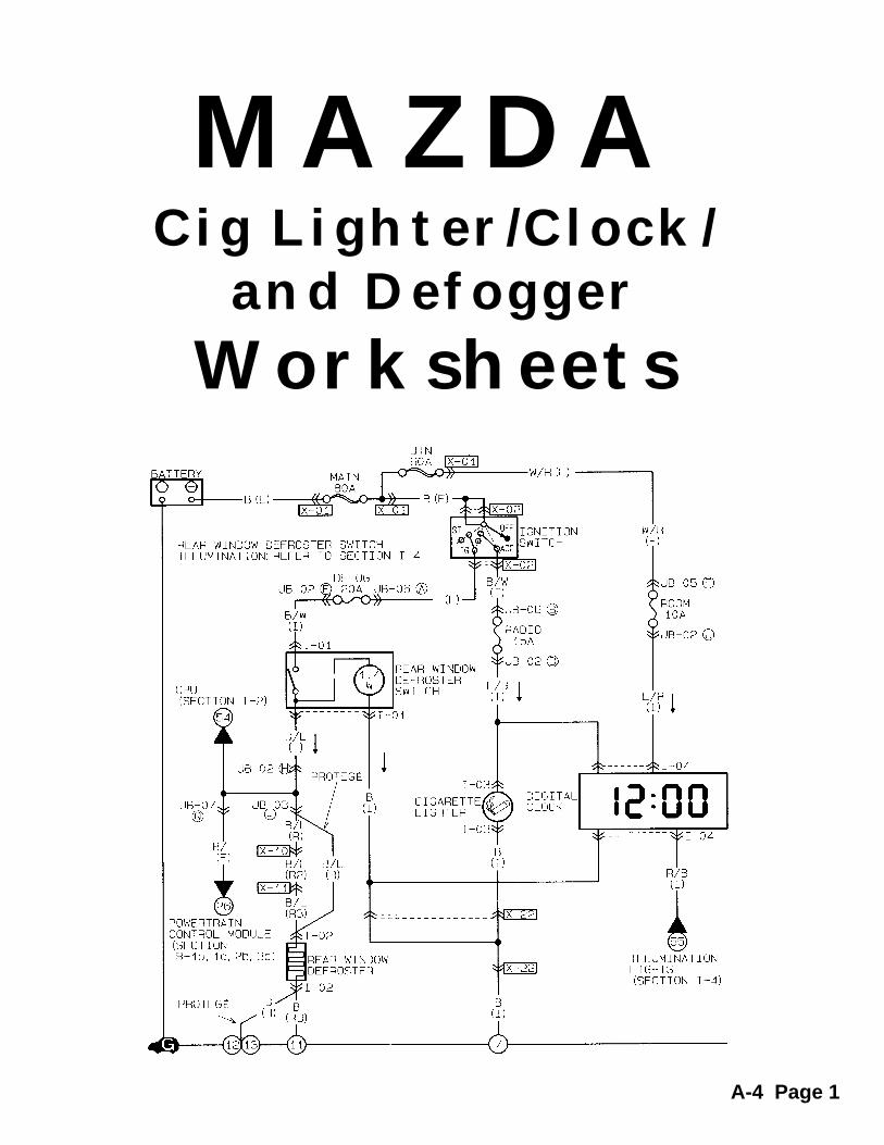
MAZDACig Lighter/Clock/
and Defogger
Worksheets
A-4 Page 1
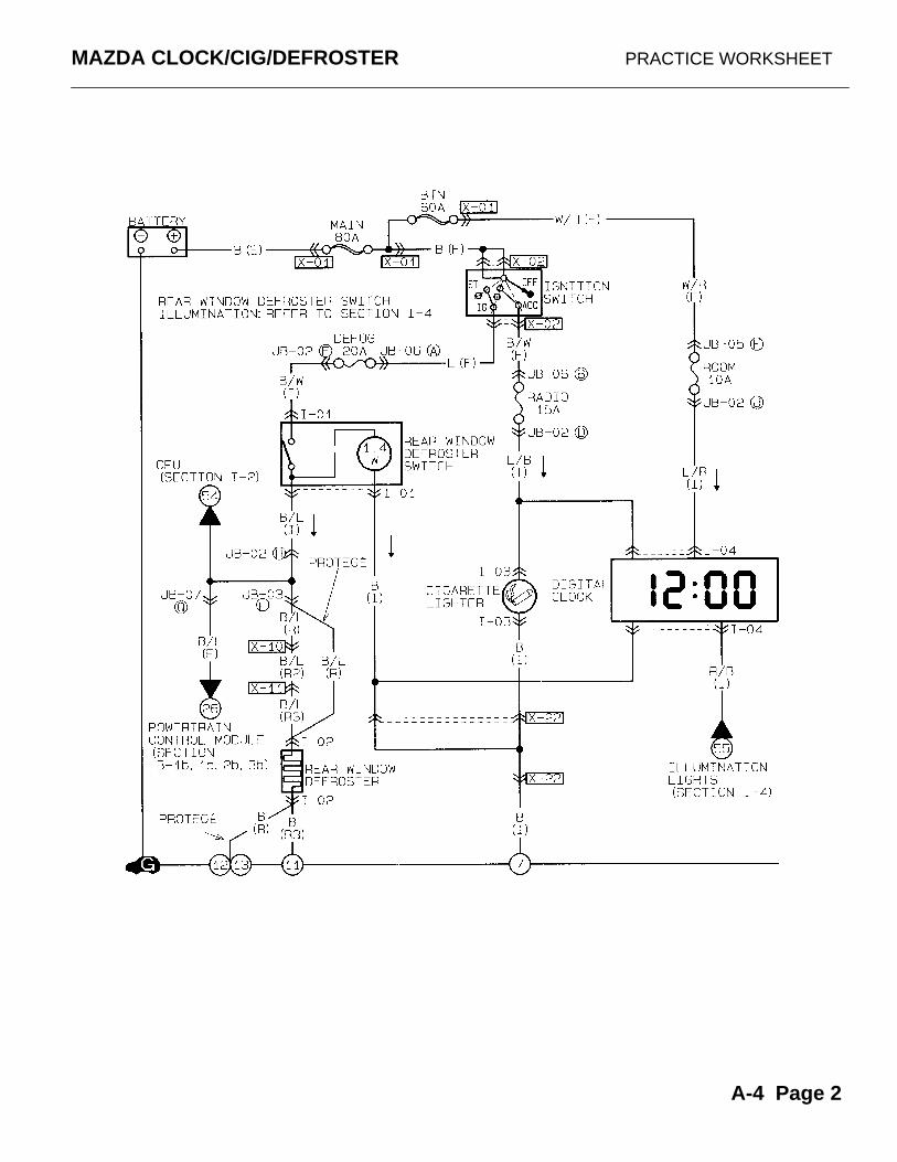
MAZDA CLOCK/CIG/DEFROSTER PRACTICE WORKSHEET
A-4 Page 2
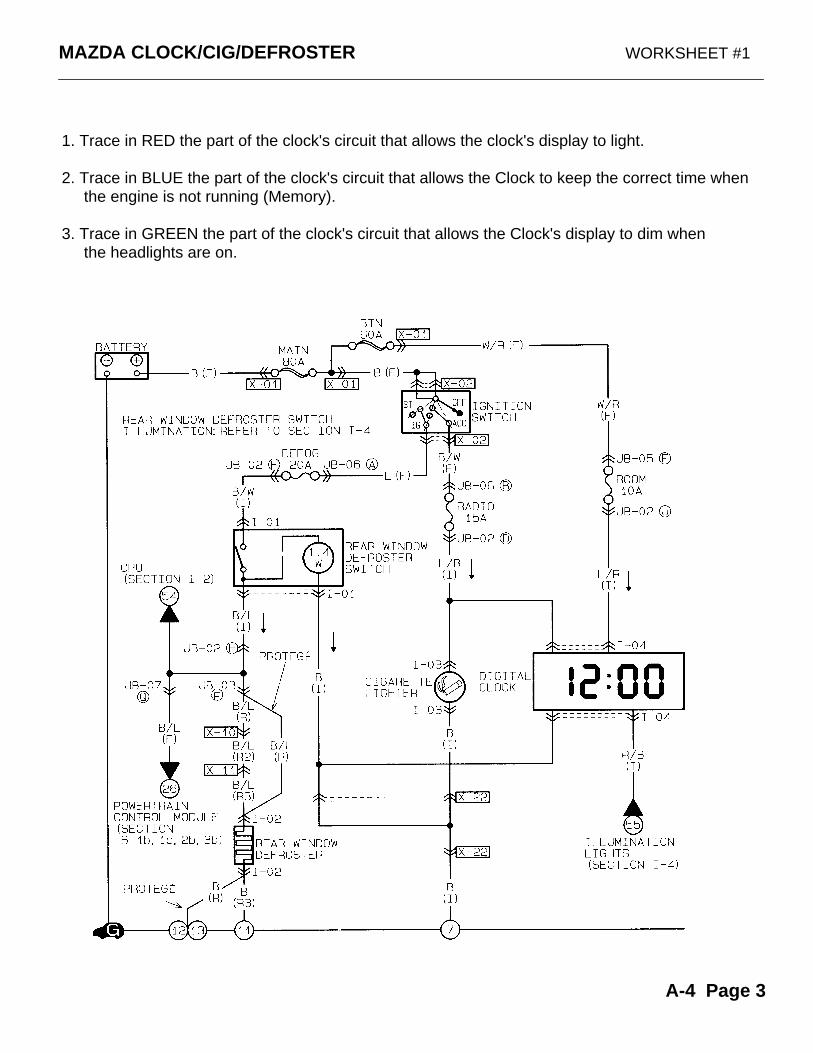
MAZDA CLOCK/CIG/DEFROSTER WORKSHEET #1
1. Trace in RED the part of the clock's circuit that allows the clock's display to light.
2. Trace in BLUE the part of the clock's circuit that allows the Clock to keep the correct time when the engine is not running (Memory).
3. Trace in GREEN the part of the clock's circuit that allows the Clock's display to dim when the headlights are on.
A-4 Page 3
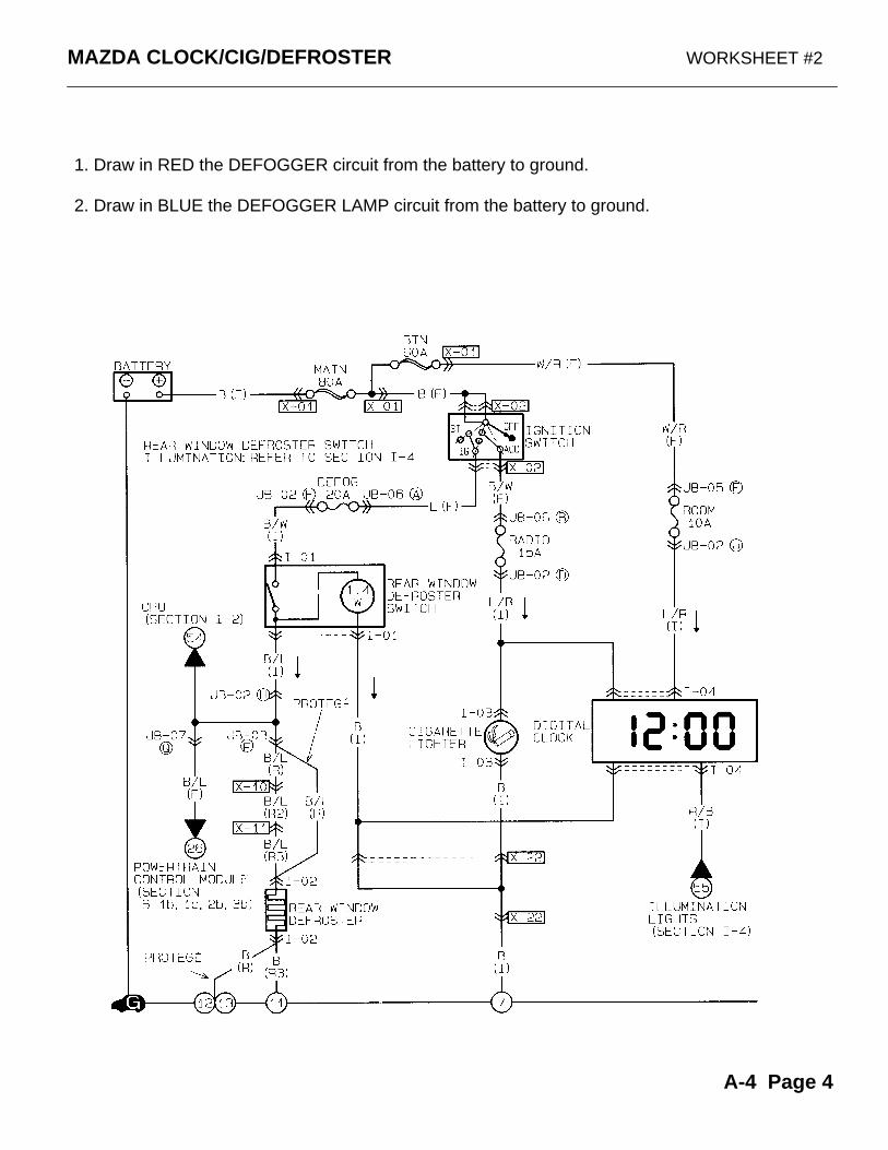
MAZDA CLOCK/CIG/DEFROSTER WORKSHEET #2
1. Draw in RED the DEFOGGER circuit from the battery to ground.
2. Draw in BLUE the DEFOGGER LAMP circuit from the battery to ground.
A-4 Page 4
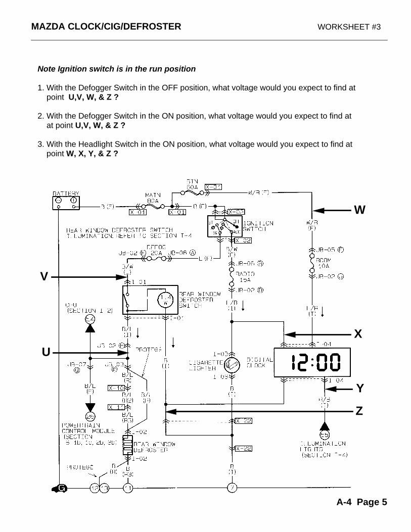
MAZDA CLOCK/CIG/DEFROSTER WORKSHEET #3
W
X
Z
Y
V
Note Ignition switch is in the run position
1. With the Defogger Switch in the OFF position, what voltage would you expect to find at point U,V, W, & Z ?
2. With the Defogger Switch in the ON position, what voltage would you expect to find at at point U,V, W, & Z ?
3. With the Headlight Switch in the ON position, what voltage would you expect to find at point W, X, Y, & Z ?
U
A-4 Page 5
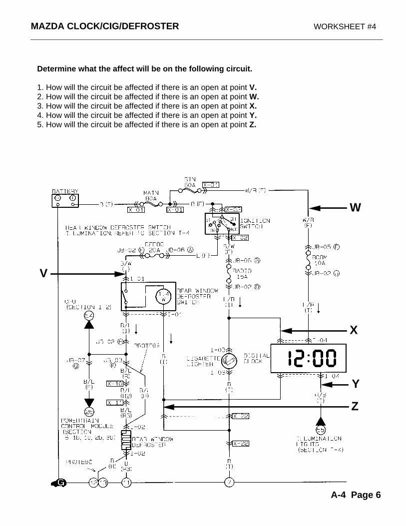
MAZDA CLOCK/CIG/DEFROSTER WORKSHEET #4
W
X
Z
Y
V
Determine what the affect will be on the following circuit.
1. How will the circuit be affected if there is an open at point V.2. How will the circuit be affected if there is an open at point W.3. How will the circuit be affected if there is an open at point X.4. How will the circuit be affected if there is an open at point Y.5. How will the circuit be affected if there is an open at point Z.
A-4 Page 6
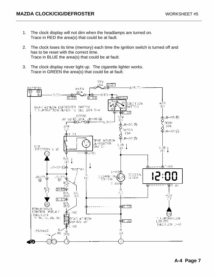
MAZDA CLOCK/CIG/DEFROSTER WORKSHEET #5
1. The clock display will not dim when the headlamps are turned on.Trace in RED the area(s) that could be at fault.
2. The clock loses its time (memory) each time the ignition switch is turned off and has to be reset with the correct time.Trace in BLUE the area(s) that could be at fault.
3. The clock display never light up. The cigarette lighter works.Trace in GREEN the area(s) that could be at fault.
A-4 Page 7
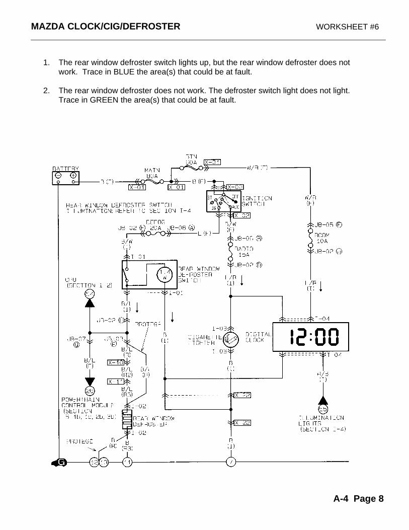
MAZDA CLOCK/CIG/DEFROSTER WORKSHEET #6
1. The rear window defroster switch lights up, but the rear window defroster does not work. Trace in BLUE the area(s) that could be at fault.
2. The rear window defroster does not work. The defroster switch light does not light.Trace in GREEN the area(s) that could be at fault.
A-4 Page 8
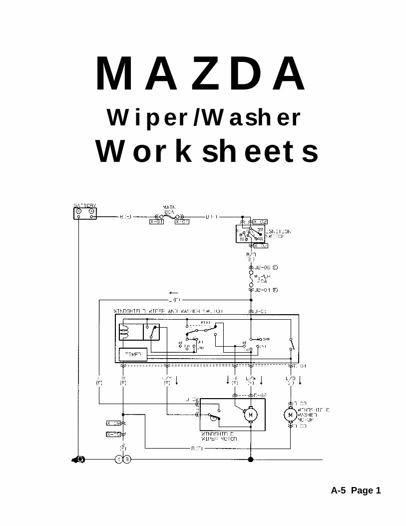
MAZDAWiper/Washer
Worksheets
A-5 Page 1
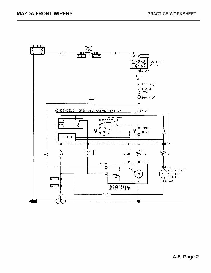
MAZDA FRONT WIPERS PRACTICE WORKSHEET
A-5 Page 2

MAZDA FRONT WIPERS WORKSHEET #1
The WIPER SWITCH is in the LOW SPEED position.
1. Trace in RED the POSITIVE power flow from the battery to the wiper motor.
2. Trace in BLUE the NEGATIVE power flow from the wiper motor to ground.
A-5 Page 3
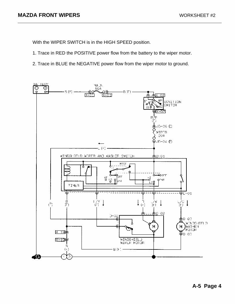
MAZDA FRONT WIPERS WORKSHEET #2
With the WIPER SWITCH is in the HIGH SPEED position.
1. Trace in RED the POSITIVE power flow from the battery to the wiper motor.
2. Trace in BLUE the NEGATIVE power flow from the wiper motor to ground.
A-5 Page 4
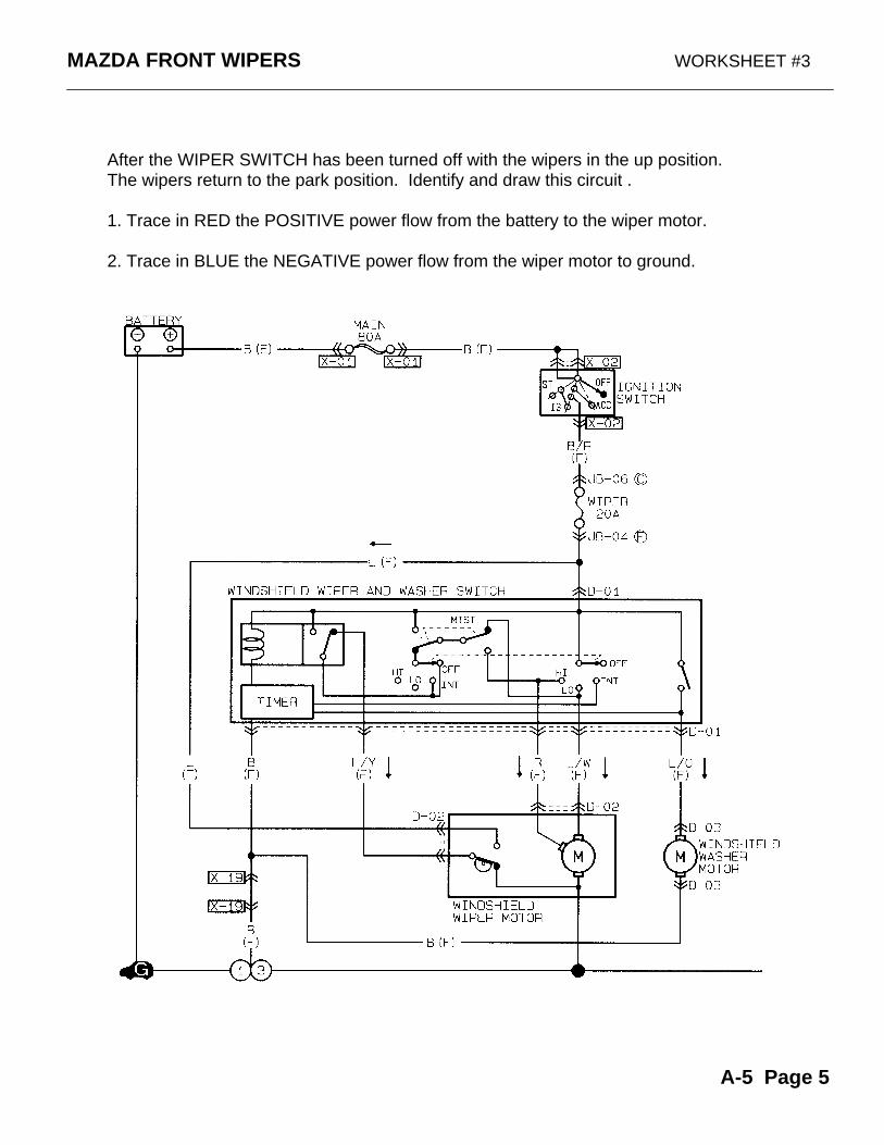
MAZDA FRONT WIPERS WORKSHEET #3
After the WIPER SWITCH has been turned off with the wipers in the up position. The wipers return to the park position. Identify and draw this circuit .
1. Trace in RED the POSITIVE power flow from the battery to the wiper motor.
2. Trace in BLUE the NEGATIVE power flow from the wiper motor to ground.
A-5 Page 5
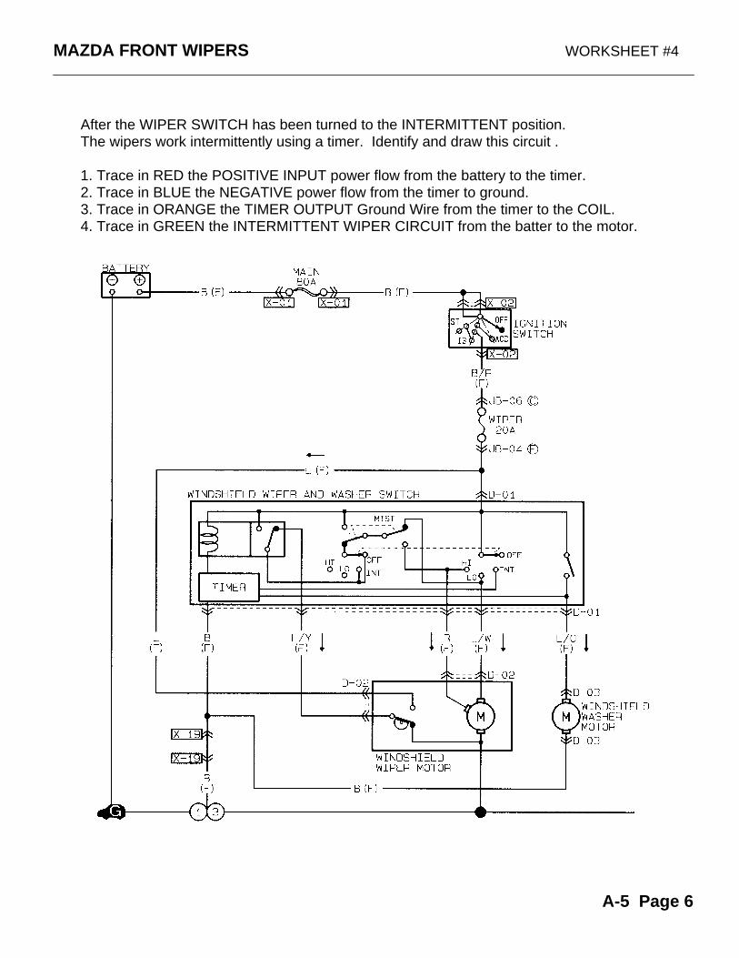
MAZDA FRONT WIPERS WORKSHEET #4
After the WIPER SWITCH has been turned to the INTERMITTENT position. The wipers work intermittently using a timer. Identify and draw this circuit .
1. Trace in RED the POSITIVE INPUT power flow from the battery to the timer.2. Trace in BLUE the NEGATIVE power flow from the timer to ground.3. Trace in ORANGE the TIMER OUTPUT Ground Wire from the timer to the COIL.4. Trace in GREEN the INTERMITTENT WIPER CIRCUIT from the batter to the motor.
A-5 Page 6
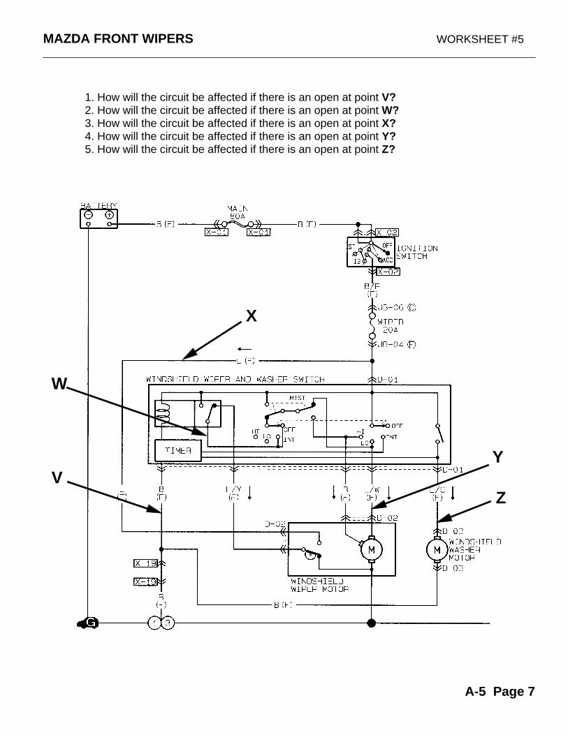
MAZDA FRONT WIPERS WORKSHEET #5
Z
W
X
Y
1. How will the circuit be affected if there is an open at point V?2. How will the circuit be affected if there is an open at point W?3. How will the circuit be affected if there is an open at point X?4. How will the circuit be affected if there is an open at point Y?5. How will the circuit be affected if there is an open at point Z?
V
A-5 Page 7
MAZDA FRONT WIPERS WORKSHEET #6
A-5 Page 8
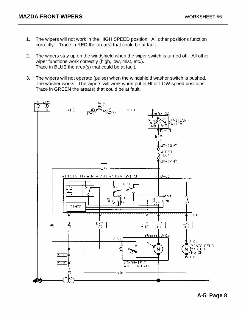
1. The wipers will not work in the HIGH SPEED position. All other positions function correctly. Trace in RED the area(s) that could be at fault.
2. The wipers stay up on the windshield when the wiper switch is turned off. All otherwiper functions work correctly (high, low, mist, etc.). Trace in BLUE the area(s) that could be at fault.
3. The wipers will not operate (pulse) when the windshield washer switch is pushed. The washer works. The wipers will work when put in HI or LOW speed positions. Trace in GREEN the area(s) that could be at fault.
MAZDA FRONT WIPERS WORKSHEET #7
A-5 Page 9
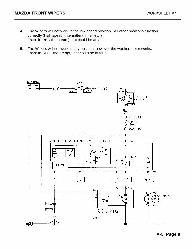
4. The Wipers will not work in the low speed position. All other positions functioncorrectly (high speed, intermittent, mist, etc.).Trace in RED the area(s) that could be at fault.
5. The Wipers will not work in any position, however the washer motor works. Trace in BLUE the area(s) that could be at fault.
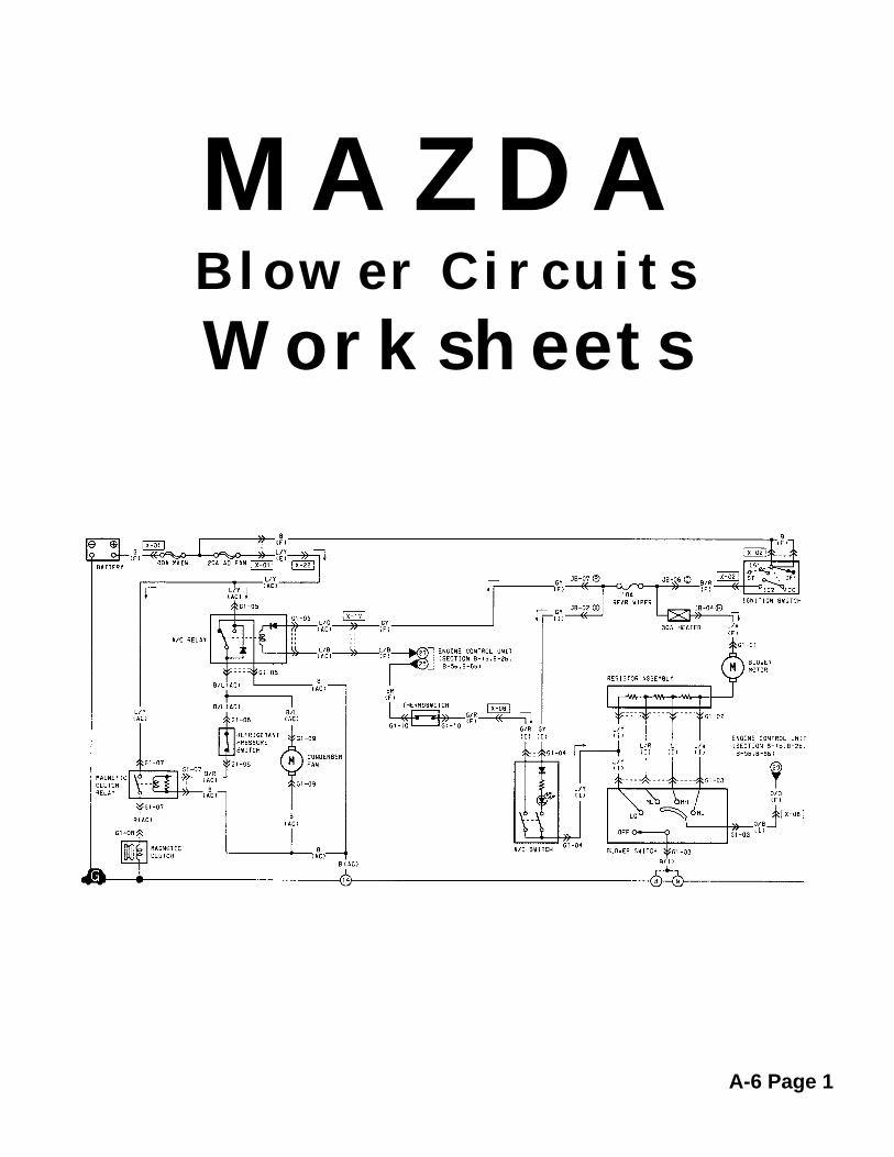
MAZDABlower Circuits
Worksheets
A-6 Page 1
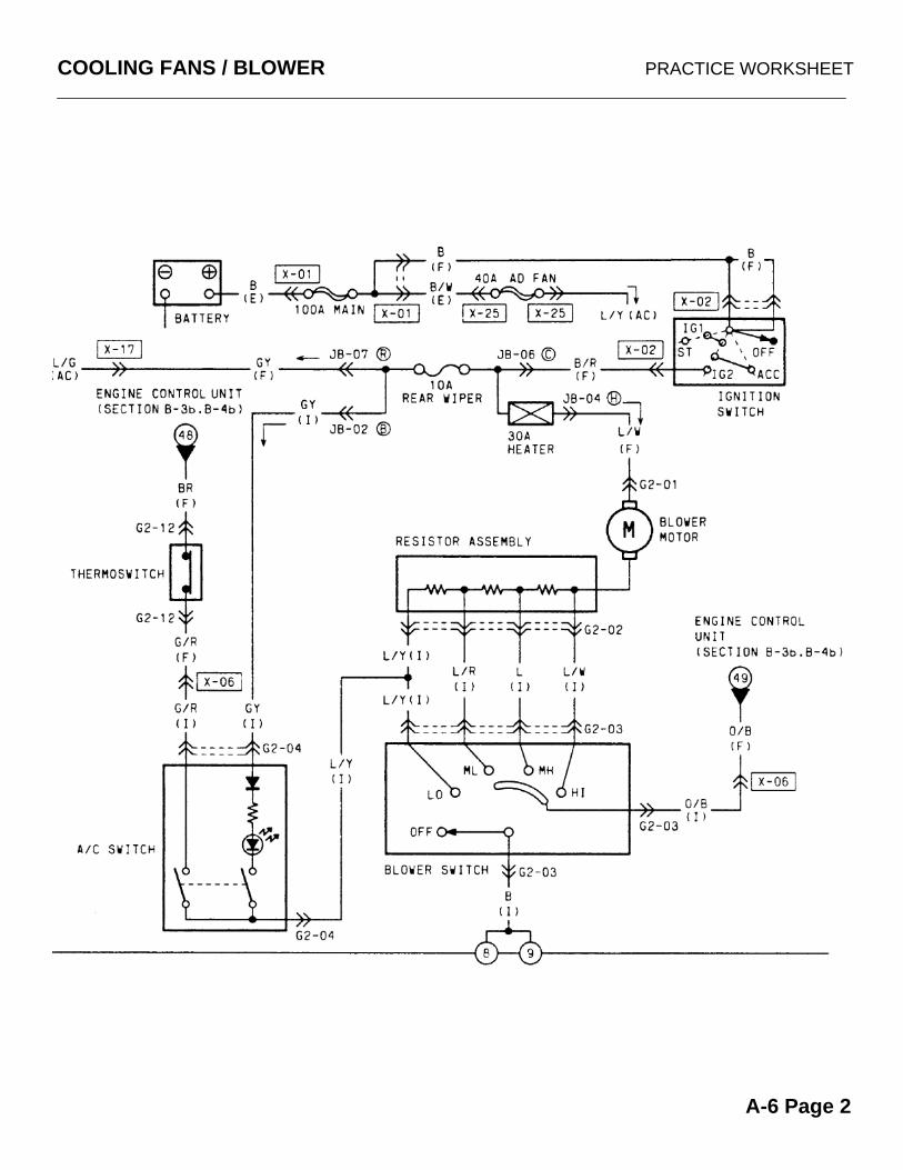
COOLING FANS / BLOWER PRACTICE WORKSHEET
A-6 Page 2
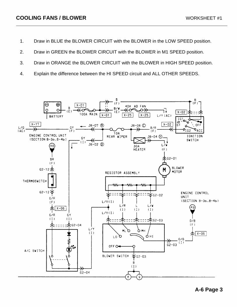
COOLING FANS / BLOWER WORKSHEET #1
1. Draw in BLUE the BLOWER CIRCUIT with the BLOWER in the LOW SPEED position.
2. Draw in GREEN the BLOWER CIRCUIT with the BLOWER in M1 SPEED position.
3. Draw in ORANGE the BLOWER CIRCUIT with the BLOWER in HIGH SPEED position.
4. Explain the difference between the HI SPEED circuit and ALL OTHER SPEEDS.
A-6 Page 3
COOLING FANS / BLOWER WORKSHEET #2
A-6 Page 4
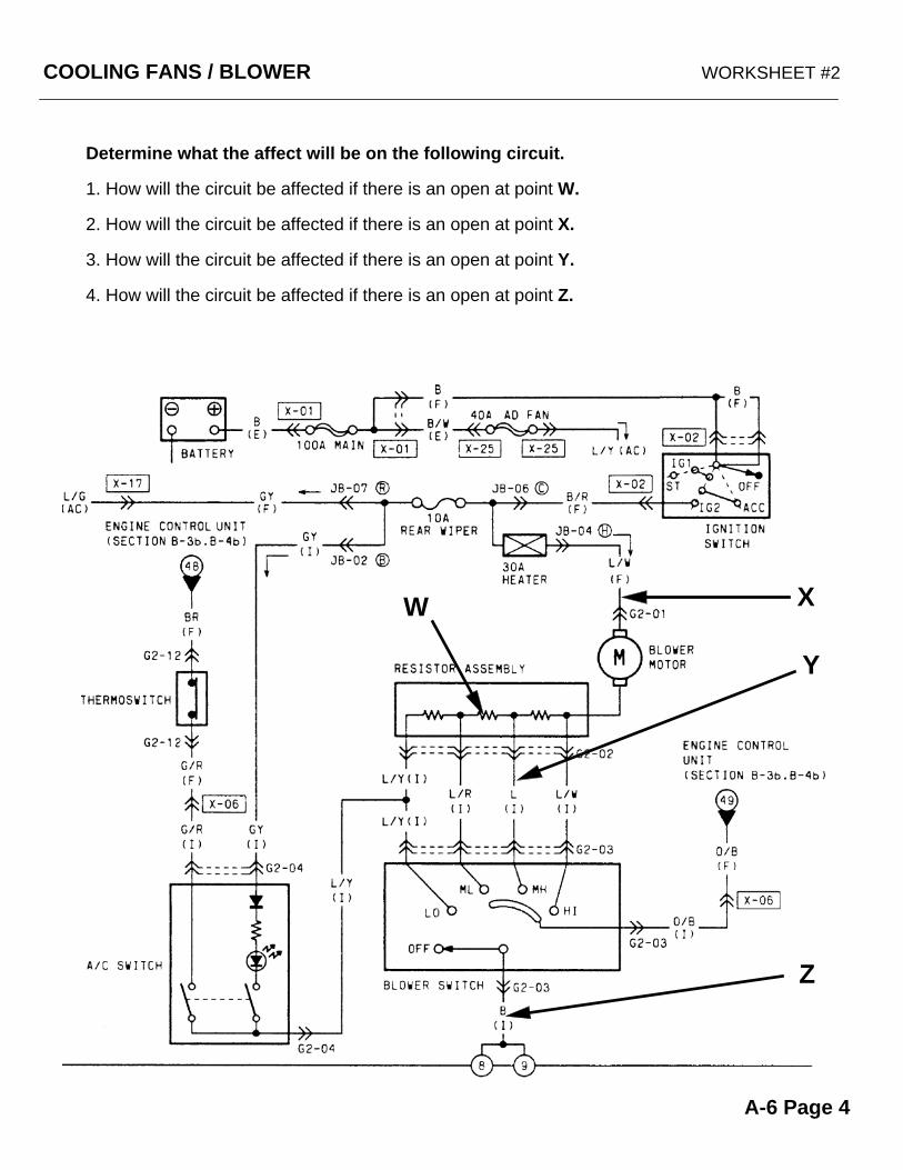
Determine what the affect will be on the following circuit.
1. How will the circuit be affected if there is an open at point W.
2. How will the circuit be affected if there is an open at point X.
3. How will the circuit be affected if there is an open at point Y.
4. How will the circuit be affected if there is an open at point Z.
Y
XW
Z
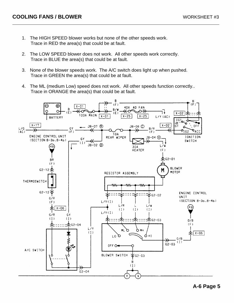
COOLING FANS / BLOWER WORKSHEET #3
1. The HIGH SPEED blower works but none of the other speeds work.Trace in RED the area(s) that could be at fault.
2. The LOW SPEED blower does not work. All other speeds work correctly.Trace in BLUE the area(s) that could be at fault.
3. None of the blower speeds work. The A/C switch does light up when pushed.Trace in GREEN the area(s) that could be at fault.
4. The ML (medium Low) speed does not work. All other speeds function correctly..Trace in ORANGE the area(s) that could be at fault.
A-6 Page 5