maxwell bracher studio air part b
DESCRIPTION
ÂTRANSCRIPT

STUDIO AIRJOURNAL 2015, SEMESTER 1, PHILIP BELESKY
MAXWELL BRACHER


Front cover: Federation Square Flinders Street Facade. Author’s own photograph.
Opposite: Federation Square frontage to Birrarung Marr. Author’s own photograph.
Table of Contents
3 Introduction
7 A1: Design Futuring 8 Grollo Tower 10 Project Orange
13 A2: Design Computation
14 Al Bahar Towers 16 M-Auditorium Dame Elisabeth Murdoch Concert Hall
19 A3: Composition / Generation 20 Toyo Ito Serpentine Pavilion 2002 22 Nordpark Cable Railway British Pavilion Shanghai Expo 2010
24 A4: Conclusion
26 A5: Learning Outcomes
28 A6: Appendix: Algorithmic Sketches
30 Bibliography
32 B1: Research Field
34 Exo Apartments 35 Australian Wildlife Health Centre Aqua Tower
36 B2: Case Study 1.0 Portrait Building
42 B3: Case Study 2.0 Arganzuela Footbridge
48 B4: Technique: Development
54 B5: Technique: Prototypes
58 B6: Technique: Proposal
66 B7: Learning Outcomes
68 B8: Appendix: Algorithmic Sketches
70 Bibliography

4 CONCEPTUALISATION
Who I am
Born and raised amongst the Eucalyptus in Emerald, Victoria, over time I have developed an acute awareness both the built and natural environments that surround me. From a very early age I was encouraged to draw and to use creative outlets as an expression of self. Whether expressed through illustration, playing the piano or the trumpet, designing aircraft liveries or ‘dream houses,’ artistry was in my blood.
It wasn’t until much later in my schooling that I decided architecture was for me. This was a career that would allow me actively engage in the world in which we live, and to shape places for a better future. My interests in the built form are wide and varied. Throughout my childhood, many happy memories directly involve country towns. The distinct architectural typology in Victorian country towns in particular has given me an intense interest in heritage architecture: how we can preserve it, interpret it, and adapt it for the future. This interest has led me to join the Heritage Advisory Committee at the Puffing Billy Railway, at which I have been volunteering my time for five years.
Conversely - perhaps contradictorily - I am fascinated in the rise of the skyscraper and the growth of Melbourne’s skyline. We are living in such an exciting phase in our city’s history. The rate of development is faster than we
have ever seen before, proliferated by massive investment from Asia and counteracted by concerns over quality control and minimum living and construction standards. Even the process from proposal to fruition has quickened: this is where computational design has a role to play.
My experience with computational design is limited at best. Up until now I have relied on tactile design: the feel of a grey lead between the fingers is all too familiar and it has been a loyal companion in my design story. However the rise of the computer is undeniable and change must come.
From my meagre point of view, computational design is causing a great shift in the industry for a couple of reasons. Firstly, it is allowing architects, engineers, urban planners, designers in general, to produce work within a much shorter time frame than what was once possible. Unfortunately, this has the added result of putting designers under increased pressure. Secondly, computers encourage the generation of forms thought previously impossible. Buildings no longer are limited by the scope of the architect’s imagination: technology now pushes design to its very limits, surprising and challenging us along the way.
I am looking forward to Studio Air inspiring me to look to the way of the future; to challenge my conceptions of design and to further my creative story. Let it begin!
Introduction

Next page: Federation Square public concert, 2014. Author’s own photograph.
CONCEPTUALISATION 5
FIG.1: SOUTHBANK EPITOMISES MODERN MELBOURNE’S RAPID GROWTH. AUTHOR’S OWN PHOTOGRAPH.


A1Design Futuring

8 CONCEPTUALISATION
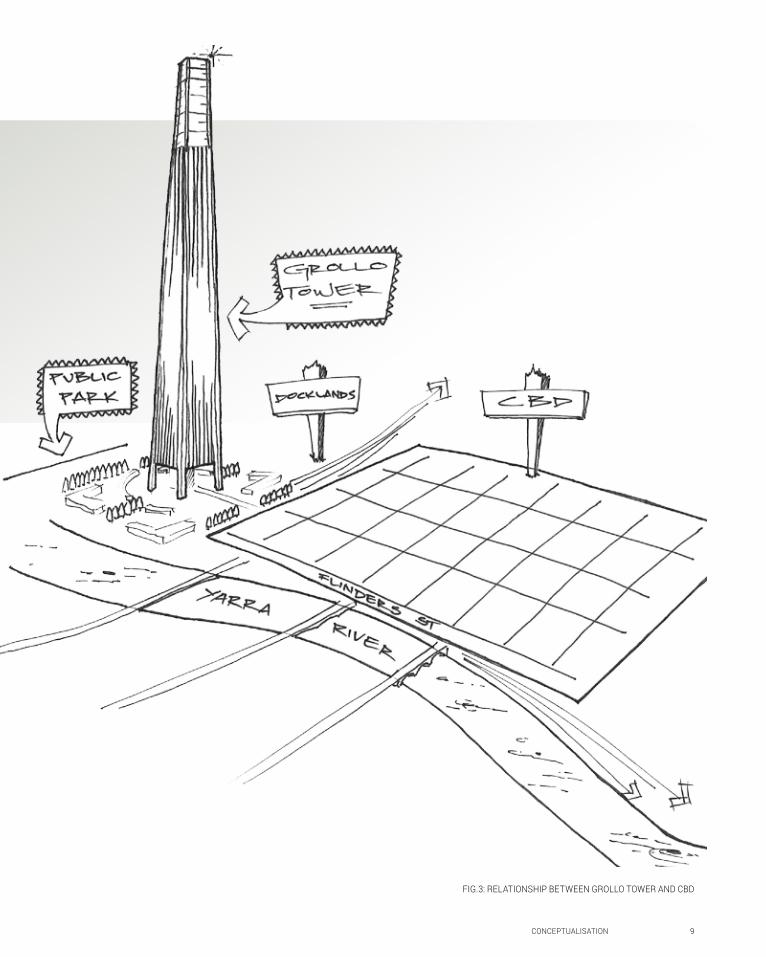
The fact that a supertall building was to be constructed in Docklands presented a series of construction issues. The soft Coode Island Silt at the site would not be sufficient for the foundations of the building. 30 metres of friction piling would be required to support the tower. It would not be practical or desirable to build any structures within close proximity to Grollo Tower simply because of the deep foundations necessary. The park was the only logical option.
Despite the Authority’s rejection of this proposal, I believe Grollo Tower proved to set a precedent for tall buildings not only in Melbourne, but across the world. This design was subsequently shipped to Dubai and proposed as the first incarnation of the Burk Khalifa. That building itself is surrounded by an immense parkland. In Melbourne, only now are we beginning to realise the possibilities of supertall living. Thanks to the potential of computation, these towers are becoming more structurally and aesthetically complex.International investors are entering our property market with ambitious plans for residential towers, but it is a shame that few present a similar standard of living that the Grollo Tower offered.
Grollo Tower
DENTON CORKER-MARSHALL / Melbourne, Australia
It was Bruno Grollo’s symbol of the future: a building that would eclipse all others to become the world’s tallest. At the time of its proposal in 1997, first at 680 then 560 metres, the building would have been at the very forefront of computerised design: both it its aesthetic and its structural capability1. The Victorian Government got so far as approving it until the Docklands Authority quashed the plans citing financial issues2.
This would be a high-tech structure, with 60 lifts and a 110-metre ‘light beacon’ crowning the tower, shooting a light beam further into the sky above Melbourne (see note 1 above). The site plan itself was different from anything in Melbourne at the time or even today. The entire Batman’s Hill precinct was to be given over to the development, with only the central footprint to be taken up by the tower. The rest of the parcel would be used as a public park.
1 Mark Baljak, ‘Grollo Tower: One man’s vision unrealised’, Urban Melbourne (2013) < https://urban.melbourne/design/2013/08/20/grollo-tower-one-mans-vision-unrealised> [accessed 3/3/15]2 Maxine McKew, ‘Grollo’s dream tower won’t crown Melbourne’s skyline’, 7.30 Report (1999) < http://www.abc.net.au/7.30/stories/s21693.htm> [accessed 3/3/15]
FIG.2 GROLLO TOWER AS IT WOULD HAVE APPEARED IN MELBOURNE’S SKYLINE. (WALKING MELBOURNE 2008)
CONCEPTUALISATION 9
FIG.3: RELATIONSHIP BETWEEN GROLLO TOWER AND CBD
FIG.2 GROLLO TOWER AS IT WOULD HAVE APPEARED IN MELBOURNE’S SKYLINE. (WALKING MELBOURNE 2008)

10 CONCEPTUALISATION
Whilst the project was never fully realised, its delivery could never be possible without computational design.
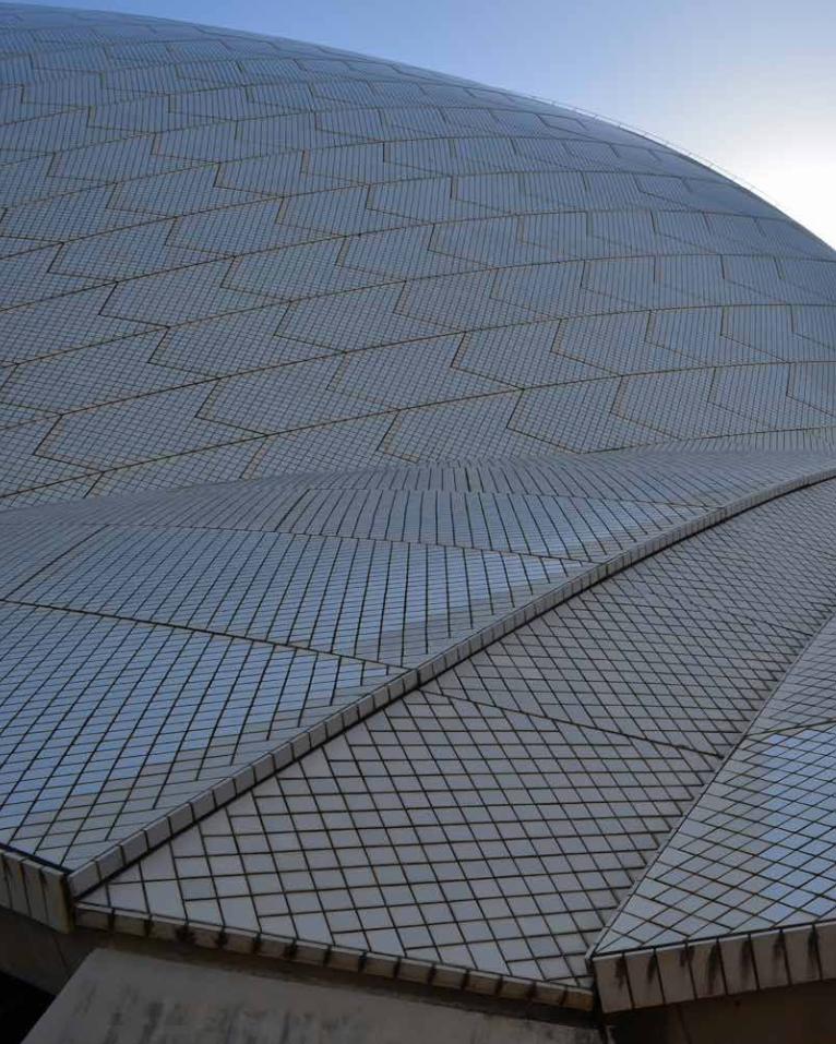
The extreme transparency of the form makes the structural components challenging to comprehend. The vast underground galleries assumedly provide structural duality in masking the foundations. To achieve the acutely angled segments, high strength steelwork would be required. Computer modelling would allow the architect to assess weak points and optimum form. The influence of Utzon’s Sydney Opera House is undeniable: the ‘sails’ of the Opera House were cut from one sphere, meaning that the ‘segments’ of this building would be of the same essential shape.
Project Orange
Foster and Partners / Moscow, Russia
Yuri Luzhkov was the ambitious mayor of Moscow who proposed an orange-shaped building along the banks of the Moscow River. Technically, the structure was to be made up of five fifteen-storey ‘wedges’ position so as to appear as a segmented orange1.
The hotel and exhibition complex was envisioned to replace an existing gallery, but was met with widespread contempt from Moscow locals. Revealed to the public in 2008, Norman Foster’s futuristic design challenges the prospective user’s understanding of gravity. The orange is traditionally seen as a symbol of opulence in Russia: spearheaded by Luzhkov’s wife, the project would send exactly that message to the world2.
1 Dina Savelyava, ‘Mayor of Moscow Yuri Luzhkov’s crazy ideas’, The Telegraph (2010) < http://www.telegraph.co.uk/sponsored/rbth/politics/8056837/Mayor-of-Moscow-Yuri-Luzhkovs-crazy-ideas.html> [accessed 4/3/15]2 AJ Welch, ‘Project Orange: New Moscow Building’, E-Architect (2008) < http://www.e-architect.co.uk/moscow/project-orange-moscow> [accessed 4/3/15]
FIG.4: ARTIST’S IMPRESSION OF ‘PROJECT ORANGE’ ON THE BANKS OF THE MOSCOW RIVER. (E-ARCHITECT 2008)

Next page: Hamer Hall refurbishment: frontage to Yarra River. Author’s own photograph.
CONCEPTUALISATION 11
FIG.6: ABSTRACT CONCEPT FOR PROJECT ORANGE
FIG.4: ARTIST’S IMPRESSION OF ‘PROJECT ORANGE’ ON THE BANKS OF THE MOSCOW RIVER. (E-ARCHITECT 2008)
FIG.5: MODEL SHOWING UNDERGROUND SPACES (WERK5 2008)


A2Design Computation

14 CONCEPTUALISATION
The world of architectural design in shifting. Brady Peters writes that “we are moving from an ear where architects use software to one where they create software.”1 Computers will play an ever-increasing role in the design process, and it is to the benefit of the architect to push the boundaries of what is possible to make his buildings better. Whilst computers have of recent times created wondrous parametric forms, we can put the power of technology to better use. From the outset of idea generation, designers must consider how a building will perform, and how aesthetic can play a role in the function of a project.
Computers allow buildings to better respond to their environment. Quick calculations can be made in regard to cost, area, materials, and climate among other factors2. Computation can been put to good use in the dry heat of Abu Dhabi. The Al Bahar Towers - 145 metres tall - are defined by what is deemed a ‘responsive facade’. The umbrella-like shades that clad the outer skin are inspired by traditional Arab geometries, and respond automatically to varying intensity of sunlight. Aedas Architects made use of a parametric description of the geometric skin to simulate its operation in response to various levels of sunlight, angles of incidence, and time of year. Computer modelling estimates there is at least a 50% reduction in solar gain thanks to the skin’s function3.
1 Brady Peters, ‘Computation Works’, Architectural Design (January 25, 2013): 1-8 2 Allison Arieff, ‘New forms that function better’, (July 31, 2013) <www.technologyreview.com/review/517596/new-forms-that-function-better/> [accessed 17/3/15]3 Saimir Lita, ‘Al Bahar Towers responsive facade’, (2013) < http://arkitekture.al/al-bahar-towers-responsive-facade-aedas/> [accessed 17/3/15]
FIG.7: AL BAHAR TOWERS’ FACADE TREATMENT

CONCEPTUALISATION 15
FIG.8: AL BAHAR TOWERS WITH SKIN CLOSED (THE SKYSCRAPER CENTRE 2012) FIG.9/10: AL BAHAR TOWERS IN RESPONSE TO SUNLIGHT (ARKITEKTURE 2013)
16 CONCEPTUALISATION
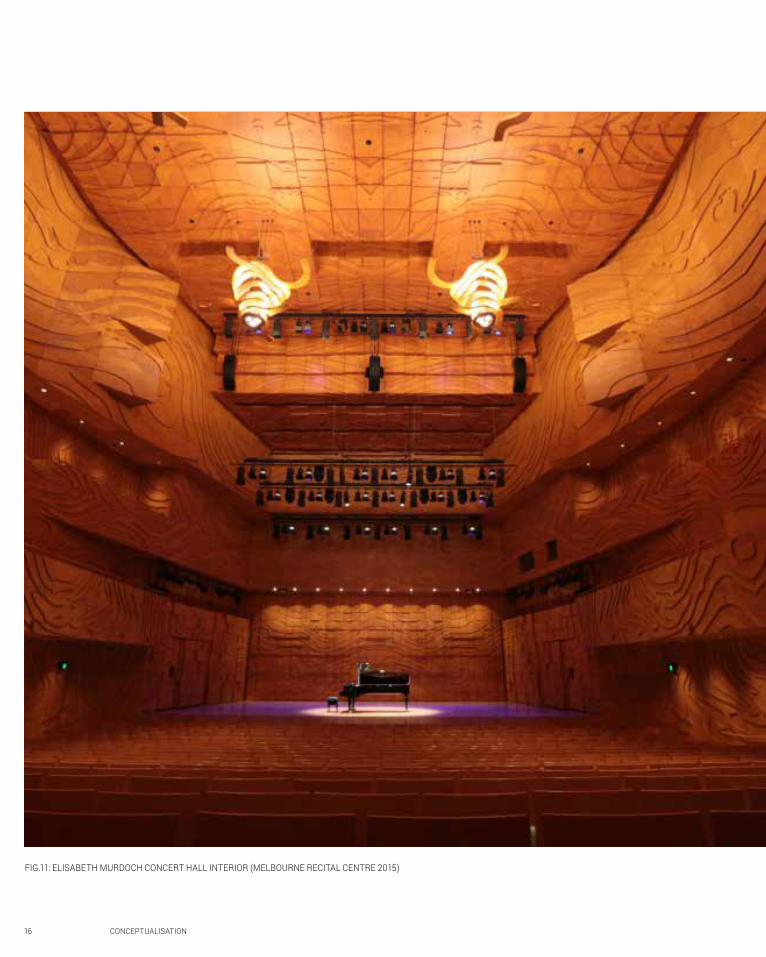
FIG.11: ELISABETH MURDOCH CONCERT HALL INTERIOR (MELBOURNE RECITAL CENTRE 2015)

CONCEPTUALISATION 17
Because of the possibilities of computational architecture, changes within a building’s design can be made very quickly and with ease. Allison Arieff suggests that due to this ability, Architects are often now more accommodating to making revisions (see note 2 on previous page). Whilst the Architect is more often than not the person directly involved with computation, simulation technology has allowed the construction industry itself to become more aware of the function of the structures they build. Design tools such as Grasshopper and Revit allow the relationships between building components and between components and function, to be more closely monitored.
Let’s consider two projects in particular, similar spaces in terms of their function, designed around closely aligned parameters. The M-Auditorium in Mumbai, India was designed so as to carry sound from the stage to the rear seats without any noticeable drop in intensity. The ceiling and walls are wave-formed, projecting volume to the very last row. Material choice was such that sound would not reverberate, but would retain its clarity. The design was the result of various simulations, such that its form was determined by its expected function. Planet 3 Studios completed this project in 20141.
Preceding the M-Auditorium by 5 years, the Elisabeth Murdoch Concert Hall within the Melbourne Recital Centre was designed by Ashton Raggatt McDougall in conjunction with Arup. The panelling of the interior of the auditorium is much more detailed than that in Mumbai: it serves more of an aesthetic function, whilst the overall form of the hall is functional. To effectively ‘seal’ the hall from outside noises, the essential form is a ‘box within a box’, mounted on giant springs to remove vibration from the trams and traffic outside. These solutions were modelled and simulated using computer technology2.
1 Planet 3 Studios Architecture, ‘M-Auditorium’, archdaily (2014) < http://www.archdaily.com/572832/m-nil-auditorium-planet-3-studios-architecture/> [accessed 17/3/15]2 Australian-Architects, ‘Melbourne Recital Centre and Melbourne Theatre Company’, Australian-Architects (2015) < http://www.australian-architects.com/en/arm>
FIG.12: M-AUDITORIUM, MUMBAI (MRIGANK SHARMA 2014)

A3Composition /
Generation
Previous page: Deborah Halpern’s ‘Angel’ at Birrarung Marr. Author’s own photograph.
20 CONCEPTUALISATION
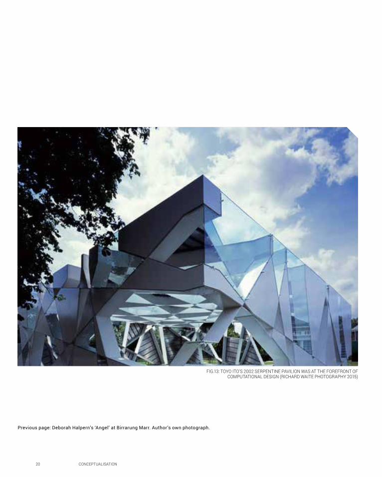
FIG.13: TOYO ITO’S 2002 SERPENTINE PAVILION WAS AT THE FOREFRONT OF COMPUTATIONAL DESIGN (RICHARD WAITE PHOTOGRAPHY 2015)
CONCEPTUALISATION 21
Where exactly does computational design begin? Is there a point in history to which we can point and say, ‘it started there’? Patrik Schumacher reports that the precursor to Computer Aided Design (CAD as we know it) - Sketchpad - was invented in 1963 by Ivan Sutherland, and just two years later the Boston Architectural Centre hosted a seminar entitled ‘Architecture and the Computer’1. Certainly the computer wasn’t embraced as essential to architecture at this point.
Today, we know that computational technology is the way of the present and future of architecture. Few would argue in 2015 that computers do not have a role to play as the industry moves forward. The contention arises when we discuss how they will be utilised. Are architects, as Peters suggested, simply becoming ‘software designers’2 - writing algorithms at the sake of good design or are computers only useful to realise potentially improved building performance, or does computation just make an Architect’s life easier?
Many express concern that by making use of algorithmic thinking, parametrics, and script cultures, Architects lose their essential ability to draw and to compose intellectual designs of their own. Much of this opinion arose in the 1960s with the arrival of the computer into Architecture.
Apart from the fact that Engineers, Planners, and Contractors were already embracing the technology, Architecture was seen as a ‘creative’ field, and that it should not be constrained by the limitations of
1 Patrik Schumacher, ‘Parametric Design: What’s Gotten Lost Amid the Algorithms, Architect (2013) <www.architectmagazine.com/design/parametric-design-whats-gotten-lost-amid-the-algorithms_o> [accessed 18/3/15]2 Brady Peters, ‘Computation Works’, Architectural Design (January 25, 2013): 1-8
the computer. The Boston Seminar of 1964 was attended by over 600 people, many young graduates, and many ‘old hats’. The overwhelming sentiment - whilst many were excited - was one of worry: what would happen to the old industry?1
Of course, in the 21st century, the industry is well aware of the implications of the computer and the potential it holds into the future. Apart from the obvious extensions to design skills to which it gifts Architects, it has become a useful information sharing resource, with forums and discussion sites allowing for the infiltration of design concepts and algorithmic methods into firms and schools of design across the world (see Peters note above). Whilst scripting cultures are progressively shared, schools of design - experienced first-hand at MSD - encourage students to master the skill of hand drawing: as there is no substitute to human design skill.
London’s Serpentine Gallery charts an interesting history of the rise of computation in Architecture, from Toyo Ito’s 2002 contribution to Sou Fujimoto’s 2013 ‘cloud pavilion’ - the very best of the architectural industry have embraced computation. The generation of Ito’s idea is apparently algorithmic - is this intellectual design at all? Simply compare the first pavilion by Zaha Hadid in 2000 to her work of today. In fifteen years, we have seen the astronomical rise of parametric design in the field: now seen as a style of its own.
3 Evangelos Kotsioris, ‘Architecture and the computer: a contested history’, The Architectural Review (2015) < http://www.architectural-review.com/essays/architecture-and-the-computer-a-contested-history/8678167.article> [accessed 18/3/15]

22 CONCEPTUALISATION
A prime example of Hadid’s work is the Nordpark Cable Railway. Hadid prepared a comprehensive plan for each of the stations along the 1.8 kilometre line, clearly parametric in design, but evidently inspired by the snow-capped peaks of Austria rising behind. Whilst Schumacher contends that Parametric design shows a complete disregard for history, it does not have to ignore its context. Hadid’s larger scale works may arguably do exactly that; but these fine-grain, relatable sculptures of genius design demonstrate a process of concept generation that goes well beyond a random ‘click’.
Another such Parametric design notably generated from its functional, historical, and environmental context is the British ‘Seed’ Pavilion that appeared at the Shanghai Exposition of 2010. Heatherwick Studio of London won the competition to design the pavilion in 2007, and if ‘Bless this Stuff’ is anything to go by, it is one of the architectural wonders of the century1. The facade is made up of 60,000 transparent rods - each 7.5 metres in length - that on the interior reveal a different seed inserted in the end. The whole composition comes together to appear like a giant dandelion, blowing in the wind.
Patrik Schumacher in his piece, ‘The Parametricist Manifesto’ - contends that Parametricism itself was adopted as a style around the turn of the 21st century. In itself it is remarkable because for the first time in Architectural history we have a predominant style that is completely generated through computational tools. Schumacher states that Parametricism displaced the uncertainty of architectural ‘style’ caused by the aftermath of Modernism and is set to endure2. Whilst the ‘new style’ ensures consistency of ambitions and principles, it is hard not to feel at aloss for the enduring loyalty of ‘yellow trace paper and a soft lead pencil’. If Parametricism is to become architecture’s future, let us not forget the past.
1 Bless This Stuff, ‘UK Pavillion at World Expo 2010 Shanghai, By Thomas Heatherwick’, Bless This Stuff (2015)< http://www.blessthisstuff.com/stuff/culture/travel/uk-pavillion-at-world-expo-2010-shanghai-by-thomas-heatherwick/> [accessed 18/3/15]2 Patrik Schumacher, ‘The Parametricisist Manifesto’, The Architect’s Newspaper (2010) <http://archpaper.com/news/articles.asp?id=4623> [accessed 18/3/15]
FIG.14: THE INTERIOR OF THE UK PAVILION: EACH ROD HOSTS A DIFFERENT SEED (KARMATRENDZ 2015)

CONCEPTUALISATION 23
FIG.15: (TOP) STATION ON THE NORDPARK CABLE RAILWAY BY ZAHA HADID (ARCHITECTURE WEEK 2013)
FIG.16: (BOTTOM) EXTERIOR VIEW OF THE UK PAVILION BY HEATHERWICK STUDIOS (KARMATRENDZ 2015)

Opposite: Eureka Tower as seen from the roof of the Australian Institute
of Architects Headquarters. Author’s own photograph.
24 CONCEPTUALISATION
What a welcome to the world of computation! Having comprehensively covered the rise and continued appreciation of the power of computational design, I am looking forward to further delving into a ‘hands on’ approach to parametrics. This outcome’s lectures, readings and tutorials have engaged my interest in architectural history, making connections with algorithmic thinking, parametrics, and scripting cultures I never expected. My research - especially in A3 - gave me faith that even in today’s computer age, design does not have to turn its back on history or environmental context.
As such, moving forward, my design approach will be to take visual, emotive, and functional cues from the site’s context and translate them into a parametric form. These cues may range from the ripples caused by a stone thrown into the creek, from the spinning motion of a Eucalyptus leaf falling to the ground, or from the feeling of calm caused by a visit to the site. I am seeking to be innovative through the feeling of surprise that the users might experience when visiting the outcome; surprise in its contextual referencing, surprise in its relatable scale, or surprise in its construction method. I do not believe the general public currently emotionally relate to parametric design in the way they relate to a Victorian terrace, a grand country hotel, or perhaps their local railway station. I hope to challenge the user to ‘feel’ this project, to ‘connect’ with it physically and emotionally.
A4Conclusion

Opposite: Royal Exhibition Building as seen through the canopy of
DCM’s Melbourne Museum. Author’s own photograph.
26 CONCEPTUALISATION
Three weeks ago, my knowledge of computational design was limited at best. I had undertaken Virtual Environments two years ago, which had given me a brief (albeit self-taught) understanding of Rhinoceros concepts. However, I began Studio Air with little confidence in my technological ability, having become all too comfortable using pens, pencils, and other manual presentation tools. One thing I have great faith in is my ability to conceive an idea, plan it methodically, and execute it to a standard - using the aforementioned manual tools - that I feel is on par with my peers.
Now, thanks to the knowledge I have obtained, I understand why and how computational design works. I am beginning to wrap my head around ‘cause and effect’ of parametrics, algorithmic thinking, and scripting. I am finding enjoyment in this process which is a welcome surprise. Had I known the implications of computing before, perhaps I would come away with even greater satisfaction in my projects. Nonetheless, I do not think computational design is the only option. I will always appreciate the architect who wields a pencil and demonstrates his intellectual skill.

A5Learning
Outcomes

Opposite: Federation Bells at Birrarung Marr. Author’s own photograph.
28 CONCEPTUALISATION
FIG.17: WEEK 2 ALGORITHMIC SKETCH: A ‘HIGH RISE’
FIG.18: WEEK 3 ALGORITHMIC SKETCH: A ‘FOREST’
A6Appendix:
Algorithmic Sketches

Bibliography
Arieff, Allison, ‘New forms that function better’, Technology Review (July 31, 2013) <www.technologyreview.com/review/517596/new-forms-that-function-better/> [accessed 17/3/15]
Australian-Architects, ‘Melbourne Recital Centre and Melbourne Theatre Company’, Australian-Architects (2015) < http://www.australian-architects.com/en/arm>
Baljak, Mark, ‘Grollo Tower: One man’s vision unrealised’, Urban Melbourne (2013) < https://urban.melbourne/design/2013/08/20/grollo-tower-one-mans-vision-unrealised> [accessed 3/3/15]
Bless This Stuff, ‘UK Pavillion at World Expo 2010 Shanghai, By Thomas Heatherwick’, Bless This Stuff (2015)< http://www.blessthisstuff.com/stuff/culture/travel/uk-pavillion-at-world-expo-2010-shanghai-by-thomas-heatherwick/> [accessed 18/3/15]
Kotsioris, Evangelos ‘Architecture and the computer: a contested history’, The Architectural Review (2015) < http://www.architectural-review.com/essays/architecture-and-the-computer-a-contested-history/8678167.article> [accessed 18/3/15]
Lita, Saimir, ‘Al Bahar Towers responsive facade’, (2013) < http://arkitekture.al/al-bahar-towers-responsive-facade-aedas/> [accessed 17/3/15]
McKew, Maxine, ‘Grollo’s dream tower won’t crown Melbourne’s skyline’, 7.30 Report (1999) < http://www.abc.net.au/7.30/stories/s21693.htm> [accessed 3/3/15]
Peters, Brady, ‘Computation Works’, Architectural Design (January 25, 2013): 1-8
Planet 3 Studios Architecture, ‘M-Auditorium’, archdaily (2014) < http://www.archdaily.com/572832/m-nil-auditorium-planet-3-studios-architecture/> [accessed 17/3/15]
Savelyava, Dina, ‘Mayor of Moscow Yuri Luzhkov’s crazy ideas’, The Telegraph (2010) < http://www.telegraph.co.uk/sponsored/rbth/politics/8056837/Mayor-of-Moscow-Yuri-Luzhkovs-crazy-ideas.html> [accessed 4/3/15]
Schumacher, Patrik, ‘Parametric Design: What’s Gotten Lost Amid the Algorithms, Architect (2013) <www.architectmagazine.com/design/parametric-design-whats-gotten-lost-amid-the-algorithms_o> [accessed 18/3/15]
Schumacher, ‘The Parametricisist Manifesto’, The Architect’s Newspaper (2010) <http://archpaper.com/news/articles.asp?id=4623> [accessed 18/3/15]
Welch, AJ, ‘Project Orange: New Moscow Building’, E-Architect (2008) < http://www.e-architect.co.uk/moscow/project-orange-moscow> [accessed 4/3/15]

Image Credits
Fig.2: The Collector, Grollo Tower, 2004 < http://www.walkingmelbourne.com/forum> [accessed 5/3/15]
Fig.4: Foster and Partners, Project Orange: New Moscow Building, 2008 < http://www.e-architect.co.uk/moscow/project-orange-moscow> [accessed 4/3/15]
Fig.5: Foster Inteko, Project Orange Presentation Model, 2008 < http://www.werk5.com/ArticlePage/Foster_and_Partners_Project_Orange?lang=EN> [accessed 4/3/15]
Fig.8: Aedas Architecture, Al Bahar Tower 2, 2012 < http://skyscrapercenter.com/building/al-bahar-tower-2/9130> [accessed 18/3/15]
Fig.9/10: Aedas Architecture, Responsive Facade, 2012 < http://arkitekture.al/al-bahar-towers-responsive-facade-aedas/> [accessed 18/3/15]
Fig.11: Melbourne Recital Centre, Elisabeth Murdoch Hall, 2015 < http://www.melbournerecital.com.au/venues/emh/> [accessed 18/3/15]
Fig.12: Mrigank Sharma, M-Auditorium, 2014 < http://www.archdaily.com/572832/m-nil-auditorium-planet-3-studios-architecture/> [accessed 18/3/15]
Fig.13: Waite, Richard, Toyo Ito, Serpentine Gallery, FT Magazine, 2015 <http://www.richardwaite.com/#photograph/720> [accessed 18/3/15]
Fig.14: Karmatrendz, The UK Pavilion designed by Thomas Heatherwick, 2010 < https://karmatrendz.wordpress.com/2010/05/29/uk-pavilion-for-shanghai-world-expo-2010-by-heatherwick-studio/> [accessed 18/3/15]
Fig.15: Huthmacher, Werner, Five Works by Zaha Hadid: Nordpark Cable Railway, 2013 < http://www.architectureweek.com/> [accessed 18/3/15]
Fig.16: Karmatrendz, The UK Pavilion designed by Thomas Heatherwick Exterior, 2010 < https://karmatrendz.wordpress.com/2010/05/29/uk-pavilion-for-shanghai-world-expo-2010-by-heatherwick-studio/> [accessed 18/3/15]
B1Research Field

34 CRITERIA DESIGN
FIG.19: EXO APARTMENTS, COLLINS STREET. THE COMPOSITE STEEL FACADE DISGUISES 8 LEVELS OF CAR PARKING (KRISTIAN GEHRADTE)

CONCEPTUALISATION 35
Patterning
One of the most obvious - and widely used - implications of parametric design is the adoption of patterning in building design. The three examples provided at right show how varied this application can be in terms of its appearance and its function.
Aqua Tower (bottom right) stands 250 metres tall over Chicago’s skyline. In Part A I concluded that parametric design can be sensitive to historical and environmental contexts, despite what is said by some detractors. Aqua Tower finds its inspiration in the rocky outcrops of the nearby Great Lakes region; whilst its aesthetic may be superficial in this way, the form of its balconies seves a useful function in prividing solar benefits and better quality of life1. Despite its parametric design, each floor required a separate calculation. Studio Gang devised the wavey facade in a way in which a rectilinear footprint could be maintained for ease of use. The concrete balconies taper away to reveal glass ‘pools’ through which sunlight infiltrates. The shading capacity of the balconies and high-performance glazing cuts back solar load. The downfall of the concrete balconies is that they lose thermal capacity during winter; a minor issue reports Gang, as the building is in every other way, ‘green’; right down to the fabrication of the balconies, which reused the same formwork, being rebent into shape for each balcony.
Melbourne’s very own Exo Apartments (left) was completed in 2012, and its perforated composite metal facade is used for another reason entirely - disguise. Eight levels of this 12-level building are devoted to car parking, the remaining four for apartments2. A similar facade treatment between the two areas sees an artistic form inspired by river stones and leaves hiding the parking and providing ventilation, and shielding the apartments from cold Docklands winds.
Finally, Healesville Sanctuary’s Australian Wildlife Health Centre was the work of Minifie van Schaik. A “cellular automation’ algorithm was used to design the brick facade, in its very nature knowing the placement of doors , windows, and openings3. The facade patterning could almost be called biomimicry were it not for the purely computational iterative process.
1 Suzanne Stephens, ‘Case Study: Aqua Tower,’ Green Source Magazine (2010) < http://greensource.construction.com/green_building_projects/2010/1001_Aqua-Tower.asp> [accessed 9/4/15] 2 Philip Hopkins, ‘Docklands launch for Exo set,’ The Sydney Morning Herald (2011) < http://www.smh.com.au/business/property/docklands-launch-for-exo-set-20110726-1hyhb.html> [accessed 9/4/15] 3 Naomi Stead, ‘Australian Wildlife Health Centre,’ Architecture Au (2006) < http://architectureau.com/articles/australian-wildlife-health-centre/> [accessed 9/4/15]
FIG. 20 TOP: AUSTRALIAN WILDLIFE HEALTH CENTRE BY MINIFIE VAN SCHAIK (PETER BENNETTS)FIG. 21 BOTTOM: AQUA TOWER BY STUDIO GANG (KURT KUCERA)


B2Case Study 1.0
FIG. 22: ASHTON RAGGATT MCDOUGALL

38 CRITERIA DESIGN
Case Study 1.0: ARM Portrait Building
Original form
Angular form
3D - skeleton form
Multiple layers
Wave form
New photograph Fewer panels More panels

CRITERIA DESIGN 39
More variation - bottom chord
Pattern on surface Hide surface
FIG. 23: PORTRAIT REAR FACADE. PROBUILD.

40 CRITERIA DESIGN
Shortlist 1 (above)
The extreme exaggeration of the bottom chord of each panel combined with the consistent overlap forms a visual relationship with the surrounding environment. The ‘drips’ recall the weeping form of local eucalypt and would lend themselves to the growth of hanging plants. The form itself appears to melt away - in itself sustainably degrading and contributing to its context. Due to its organic nature, this example could make use of recycled materials, or materials that are naturally non-conformist.
Shortlist 2 (left)
If turned on its side, the overall form of this example would make a visually interesting bridge that could be used in multiple ways. The variably ‘bulges’ could each host a different function, or user group. For example; the first may function as a gallery of natural flora and fauna, the second may be community garden, the third a public art space, and the fourth a viewing platform. The density of the panels means that its functional and aesthetic form would retain their integrity.

CRITERIA DESIGN 41
Shortlist 3 (left)
Patterned panels have been deliberately run vertically to allow them to potentially perform as sun shades / louvres. The cascading wave form of the ‘roof’ would perform well under wind load, and aesthetically each ‘wave’ may denote a new component or function. Because each of the panels are planar, there would be little embodied energy in the manufacture of each piece - perhaps from recycled timber or cardboard. By stretching a flexible cover between panels, lightweight weather protection could be achieved.
Shortlist 4 (below)
Whilst the other examples shown on this page prioritise aesthetic qualities and materiality, the example below may prove a convenient and efficient way of mapping locii for planter boxes, seating, ‘portholes’ or any number of other components. The pattern has been aligned with sectioned panels, thereafter the panels have been removed. Alternatively, such a pattern could be cut from a single sheet, providing an attractive facade, disguising a functional structure underneath.
FIG. 24: ARTIST’S IMPRESSION. ADIYES

B3Case Study 2.0
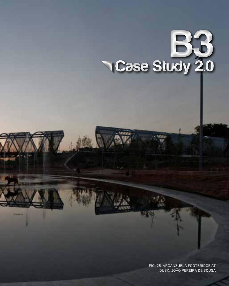
FIG. 25: ARGANZUELA FOOTBRIDGE AT DUSK. JOÃO PEREIRA DE SOUSA

44 CRITERIA DESIGN
Case Study 2.0: Arganzuela Footbridge, Madrid
The Manzanares River runs through the centre of the Spanish capital, Madrid. Between 2005 and 2010 a major highway that bordered the river was buried underground; providing the opportunity to open the riverbank to a new central park. Dominique Perrault Architecture was commissioned to design the longest bridge connecting the banks. The Arganzuela Footbridge is a pedestrian and bicycle bridge designed in two section 150 and 128 metres long, respectively. It was completed by the end of 2010[1].
The bridge reads as a series of interconnecting systems: a prefabricated steel triangulated frame in the shape of two cones, a spiral of cladding, an opposing spiral of delicate wires, and a timber deck. It is strategically located to provide views to the nearby Toledo bridge, and is intended as a summer house for visitors to the park. At night the spiral is lit up as a beacon from across the metropolis.
I think Perrault was set a huge task to design such a large structure for a multitude of users in such a significant location. I believe his design has been so successful because he carried a strong concept from beginning to end, and was uncompromising in its execution. The fact that the bridge is divided into two separate components adds visual interest but also succeeds in breaking down the dominant scale into two more relatable, human-scale parts.
1 Sumit Singhal, ‘Arganzuela Footbridge in Madrid, Spain by Dominique Perrault Architecture’, AECCafe (2011) <http://www10.aeccafe.com/blogs/arch-showcase/2011/12/02/arganzuela-footbridge-in-madrid-spain-by-dominique-perrault-architecture/> [accessed 20/4/15]
REVERSE-ENGINEERED ARGANZUELA
FOOTBRIDGE {6}
FIG.26: ARTIST’S IMPRESSION OF THE ARGANZUELA
FOOTBRIDGE. DOMINIQUE PERRAULT ARCHITECTS.

CRITERIA DESIGN 45
REVERSE-ENGINEERED ARGANZUELA
FOOTBRIDGE {6}
The Process
I began by examining the structural frame of the Arganzuela Footbridge; a triangular grid wrapped around a very simple cone. I had some idea about how this might be constructed using Grasshopper, in fact I had a few. Firstly, I created the cone shaped surface by lofting three progressively scaled circles. I then created a triangulated planar grid which I intended to ‘wrap’ the cone in {1}. First dead end! Even if I had have achieved this, I think I would have struggled to loft the spirals. The next attempt involved dividing both the surface and the circles, then joining each point with a line. The problem I faced here is that the lines would not ‘bend’ around a curve, so I ended up with a hexagonal frame {2}. Instead, I divided just the three circles from which I had lofted and ‘shifted’ the list to create essentially a cone-shaped gridshell {3}. I then attempted to offset each of the diamonds onto a surface, however the resemblance to the original was poor {4}. In order to create the spirals to the correct degree, I used a single unit, then copied, pasted, and scaled, to enlarge the cone {5}. The issue I had here was the lofts did not join, nor did the lines of the frame. Success came about when I decided not to offset the curves and scaled and joined prior to lofting. This way the loft was continous. I then ‘piped’ the frame, resulting in a model not dissimilar to Perrault’s design {6}.
{1}{2}
{3}
{4}
{5}

Considering my level of experience regarding Grasshopper, I am really pleased by the result of the reverse engineered project: Arganzuela Footbridge. The overall form of the bridge including the triangulated structural frame bears a strong resemblance to the original.
I had originally intended to loft the surfaces between the boundaries of each individual triangle, as Perrault’s bridge does. I found difficulty in separating each boundary from the overall structure, especially so because the curves extended for the whole length of the bridge, as opposed to being separate units for each unit. Therefore, the scale of the frame is smaller in my attempt, and the lofted curve arises from the space between two curves only.
I would have liked to parametrically design the walkway component more precisely, however I resorted to lofting two sets of slightly different curves to create surfaces, and placed them parallel to one another.
Design Potential
By stretching the existing definition over an elongated distance, the triangular framing elements may provide visual variation. I would like to experiment with creating a frame between different shapes and lofting more variable surfaces. I hope to be able to wrap this triangular grid over a form with more dimensionality, for example adding additional ‘arms’ to the design, perhaps following a more curvilinear path.
46 CRITERIA DESIGN

CRITERIA DESIGN 47
FIG.26: RENDERING OF THE
ARGANZUELA FOOTBRIDGE.
DOMINIQUE PERRAULT ARCHITECTS.
FIG.27: REVERSE ENGINEERED
PROJECT BY AUTHOR.


B4Technique: Development
FIG. 28: DOMINIQUE PERRAULT ARCHITECTS
50 CRITERIA DESIGN

CRITERIA DESIGN 51
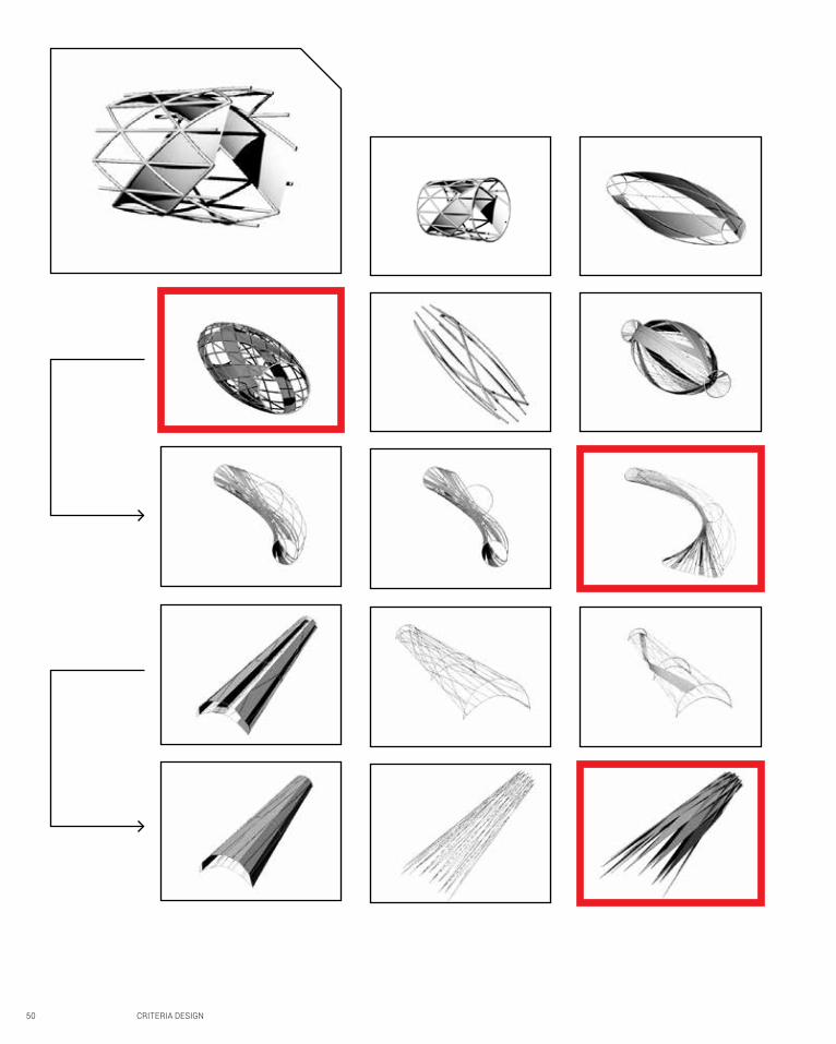
The most success was achieved at either end of the ‘creative spectrum’. That is, either when strict rules regarding geometries were followed, or when rules were disregarded altogether.
The first example follows a similar design to London’s ‘St’ Mary’s Axe’ otherwsie known as the ‘Gherkin’. The central framing element is larger than those at either end, forming a restrained bulge through which the curves flow with discipline.
Example two does the opposite. It achieves its form by rotating the framing elements at either end, and shifting them to form a long arc. Because the lines between beginning and end follow the shortest possible route, they are collected on only one side of the structure, leaving the opposite side exposed, but with clear viewlines.
Finally, the third highlighted example creates a surface by lofting between curves of opposite direction. At the opposite end, the surfaces intersect to create a vague ‘honeycomb’ structure.

52 CRITERIA DESIGN

CRITERIA DESIGN 53
A new form was created to which the original algorithm was applied in the fourth example. The benefit of this widened form is the potential for multiple streams of traffic to move through the structure concurrently. Its design is clean, easily readable, and open to construction using sustainable materials. It could easily be refurbished at a later date, but its structural integrity would remain due to the extra bracing provided by the enlarged surface.
By reducing the number of curve divisions, lofting between curves, and then removing the curves themselves, I have created an interesting form that recalls the native grasses and reeds that can be found in large numbers on site. With either end enclosed, users are guided into and through the structure. However where the surfaces split, light is welcomed and views can be appreciated. Its generous dimensions allow a number of users to make use of the space.

B5Technique: Prototypes

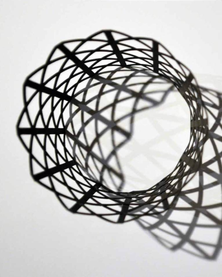
TOP LEFT: LASER-CUT FRAME PRIOR TO
INSTALLATION OF CIRCULAR FRAMING
MIDDLE: SAME MODEL
DEMONSTRATING SHADOW EFFECTS
WHEN PLACED HORIZONTALLY
TOP RIGHT: MODEL SHOWN FOLLOWING
INSTALLATION OF CIRCULAR
FRAMING AND SPIRAL SURFACES
LEFT: THE LINEWORK SENT TO
THE FABLAB FOR CUTTING
56 CRITERIA DESIGN

CRITERIA DESIGN 57
Prototyping
Time constraints meant that I only had time to fabricate one sample prototype. For this reason, I chose the most basic structural unit as exhibited by Case Study 2.0. The triangulated frame is warped so as to span between two circular framing elements of different sizes. The liework at left illustrates how the grid is altered to cover this space. The grid itself is self-supporting; that it, horizontal/vertical and diagonal members brace one another from collapsing under its own weight. The conical shape of the model in fact adds to its structural integrity as it is unable to warp or collapse in any one direction.
The prototype is manufactured from 200gsm black and white card - in itself not a very robust or rigid material, however when designed in such a form, providing sufficient support in both directions, but more significantly under vertical compression. When oriented as at right, loads are transferred directly to the foundation surface. The model does not show as much strength when placed on its side (as at middle). Prior to the installation of circular framing and spiral surfaces (as at top left), the frame cannot withstand as large a load in compression, but is performs well under tensile conditions.
The orientation of the circular framing elements - that is, perpendicular to the triangulated grid, ensures resistance to loads from the horizontal and vertical plane. Whilst the spiralling surfaces were originally intended as simple aesthetic devices, the extra depth that they provide, coupled with the bracing function which they perform, prove that their installation at the Arganzuela Footbridge was as much for the structural and function performance of the bridge.
If multiple units of this type were to be installed as part of my design, the critical factor would be the joining of one to another. The structural performance of individual units is proven, it must be ensured that the joints between do not compromise the integrity of the system. It is assumed that the materiality of individual units could be varied, as each triangular framing element could be constructed individually, together spanning large distances.
58 CRITERIA DESIGN

CRITERIA DESIGN 59
B6Technique: Proposal
60 CRITERIA DESIGN
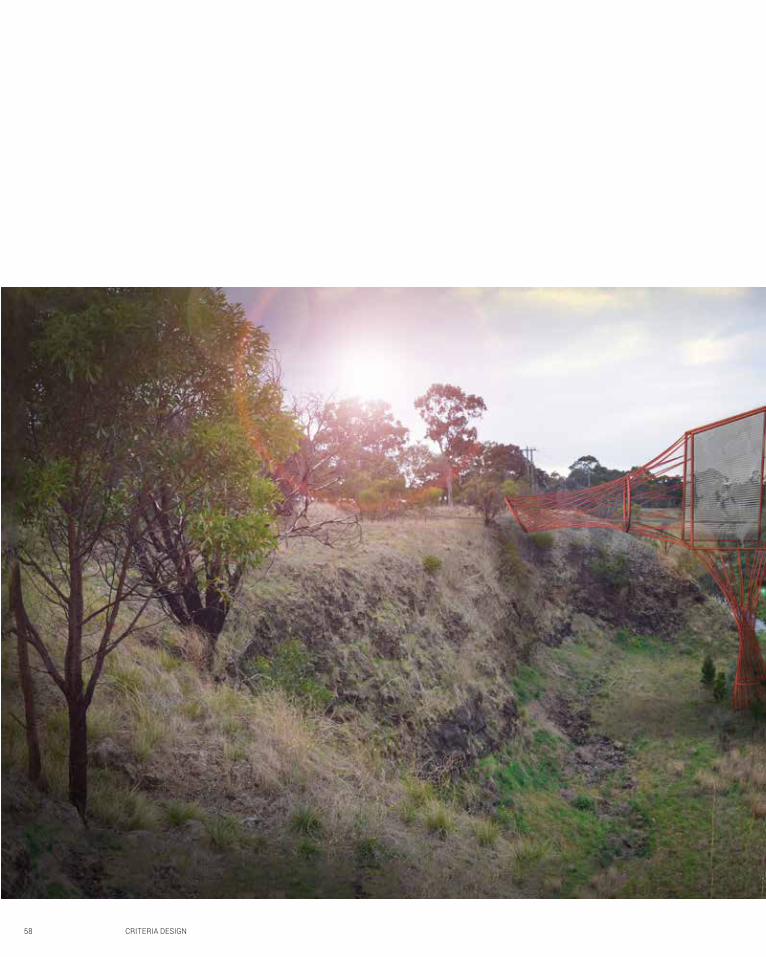
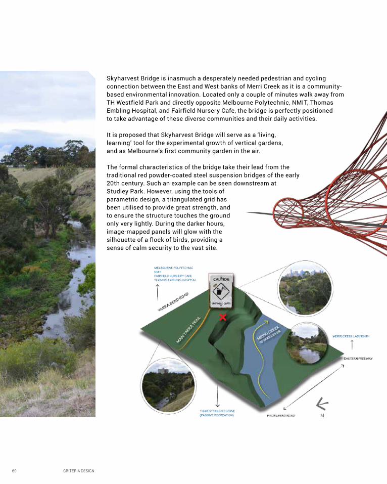
Skyharvest Bridge is inasmuch a desperately needed pedestrian and cycling connection between the East and West banks of Merri Creek as it is a community-based environmental innovation. Located only a couple of minutes walk away from TH Westfield Park and directly opposite Melbourne Polytechnic, NMIT, Thomas Embling Hospital, and Fairfield Nursery Cafe, the bridge is perfectly positioned to take advantage of these diverse communities and their daily activities.
It is proposed that Skyharvest Bridge will serve as a ‘living, learning’ tool for the experimental growth of vertical gardens, and as Melbourne’s first community garden in the air.
The formal characteristics of the bridge take their lead from the traditional red powder-coated steel suspension bridges of the early 20th century. Such an example can be seen downstream at Studley Park. However, using the tools of parametric design, a triangulated grid has been utilised to provide great strength, and to ensure the structure touches the ground only very lightly. During the darker hours, image-mapped panels will glow with the silhouette of a flock of birds, providing a sense of calm security to the vast site.

CRITERIA DESIGN 61

Skyharvest Bridge
62 CRITERIA DESIGN

CRITERIA DESIGN 63

64 CRITERIA DESIGN

CRITERIA DESIGN 65

Author’s own photograph.
66 CRITERIA DESIGN
Whilst I am pleased with how far I have come with Studio Air thus far, the course has not been without its challenges. I am not completely satisfied with my ability to apply parametric tools, and it has been difficult to convert my thinking as to how I design (conscious/unconscious). At this stage I have not fully interrogated the possibilities of the brief, and in fact I feel that the time given over to design including context analysis, users, conditions, has been insufficient. It is unfortunate that this course does not encourage the useage of the traditional design process: it simply feels wrong.
My skills with computational design are growing - albeit slowly - and I am beginning to realise the possibilities which are imbued in the process. It is only now that I am appreciating the potential - when prototypes and renders emerge, where design is finally tangible to touch and experience as it should be. I am certain these computational tools have their place in architecture, but I don’t believe we should forget how do design using our own given talents to their best use.
Finally, if anything, Air has reminded me of the strong mathematical basis of architectural design. We cannot have design unless we have logic, they are indelibly linked and parametric programs are helping us to realise the best possibilities for the future if not as a designer but as a designer’s assistant.

B7Learning
Outcomes
CRITERIA DESIGN 67

68 CRITERIA DESIGN
FIG.29: FIELD FUNDAMENTALS FIG.30: CULL
FIG.31: ATTRACTOR POINTS FIG.32: EVALUATING FIELDS
B8Appendix:
Algorithmic Sketches
CRITERIA DESIGN 69

70 CRITERIA DESIGN
Bibliography
Hopkins, Philip, ‘Docklands launch for Exo set,’ The Sydney Morning Herald (2011) < http://www.smh.com.au/business/property/docklands-launch-for-exo-set-20110726-1hyhb.html> [accessed 9/4/15]
Singhal, Sumit, ‘Arganzuela Footbridge in Madrid, Spain by Dominique Perrault Architecture’, AECCafe (2011) <http://www10.aeccafe.com/blogs/arch-showcase/2011/12/02/arganzuela-footbridge-in-madrid-spain-by-dominique-perrault-architecture/> [accessed 20/4/15]
Stead, Naomi, ‘Australian Wildlife Health Centre,’ Architecture Au (2006) < http://architectureau.com/ar-ticles/australian-wildlife-health-centre/> [accessed 9/4/15]
Stephens, Suzanne, ‘Case Study: Aqua Tower,’ Green Source Magazine (2010) < http://greensource.con-struction.com/green_building_projects/2010/1001_Aqua-Tower.asp> [accessed 9/4/15]

CRITERIA DESIGN 71
Image Credits
Fig.19: Gehradte, Kristian, Architecture Exteriors C11-Exo Docklands, 2013 <http://www.kgphotography.com.au/portfolio-items/architecture-exteriors-c11-exo-docklands/> [accessed 14/4/15]
Fig. 20: Bennetts, Peter, Australian Wildlife Health Centre, 2012 <http://www.archello.com/en/project/australian-wildlife-health-centre/899738#> [accessed 14/4/15]
Fig. 21: Kucera, Kurt, Aqua Tower in Chicago, 2014 <http://kurtkucera.org/new-lucas-museum-promises-exciting-architecture/> [accessed 14/4/15]
Fig. 22: Ashton Raggatt McDougall, Swanston Square Artist’s Impression, 2010 <http://ourvision.com.au/blog/wp-content/uploads/2011/07/ov_cb_ext4.jpg> [accessed 20/4/15]
Fig. 23: Probuild, An Iconic Facade for an Iconic Landmark, 2015 <http://www.probuild.com.au/projects/projects/my80-apartments-44> [accessed 20/4/15]
Fig. 24: Adiyes, Design Ideas: Apartment: Portrait, 2011 <http://adesignideas.blogspot.com.au/2011/04/apartment-potrait-melbourne-australia.html> [accessed 20/4/15]
Fig. 25: de Sousa, João Pereira, Arganzuela Footbridge, 2011 <http://mimoa.eu/projects/Spain/Madrid/Arganzuela%20Footbridge> [accessed 24/4/15]
Fig. 26: Dominique Perrault Architects, Rendering 1, 2010 <http://www10.aeccafe.com/blogs/arch-showcase/2011/12/02/arganzuela-footbridge-in-madrid-spain-by-dominique-perrault-architecture/>
Fig. 27: Dominique Perrault Architects, Rendering 2, 2010 <http://www10.aeccafe.com/blogs/arch-showcase/2011/12/02/arganzuela-footbridge-in-madrid-spain-by-dominique-perrault-architecture/>
Fig. 28: Dominique Perrault Architects, Rendering 3, 2010 <http://www10.aeccafe.com/blogs/arch-showcase/2011/12/02/arganzuela-footbridge-in-madrid-spain-by-dominique-perrault-architecture/>
