maxima 2 operator’s manual - carrier dealer · 2 maxima 2 operator’s manual this guide has been...
TRANSCRIPT

2
MAXIMA 2 OPERATOR’S MANUAL
This guide has been prepared for the operator of Carrier Transicoldtrailer refrigeration units. It contains basic instructions for the dailyoperation of the refrigeration unit as well as safety information,troubleshooting tips, and other information that will help you todeliver the load in the best possible condition. Please take the timeto read the information contained in this booklet and refer to itwhenever you have a question about the operation of your CarrierTransicold unit.
Your refrigeration unit has been engineered to provide long,trouble--free performance when it is properly operated andmaintained. The checks outlined in this guide will help to minimizeover--the--road problems.
Maintenance program will also help to control operating costs,increase the unit’s working life, and improve performance.
Carrier Transicold has an on--going product quality upgrade policy.As a result, specifications are liable to change without notice.

GB
3
CONTENTS
Page
UNIT IDENTIFICATION 4
SAFETY 6
FEATURES 8
MICROPROCESSOR CONTROLLER 10
DESCRIPTION 10
PRE--TRIP INSPECTION 18
UNIT OPERATION 20
FAULT ALARM DISPLAY 22
FUSES 24
SOLID-STATE CONTROLLER 25
DESCRIPTION 25
PRE--TRIP INSPECTION 30
UNIT OPERATION 32
FUSES 38
TROUBLESHOOTING 40
UNIT MAINTENANCE 41
UNIT MAINTENANCE SCHEDULE 43
DESCRIPTION OF SERVICE REQUIREMENTS 44
BELTS 45
FILTERS 47
PRODUCT LOADING 48
RECOMMENDED TRANSPORT TEMPERATURES 51
STANDBY OPERATION GUIDELINES 52
MANUFACTURER INFORMATION 53
“A.T.P. EUROPE” REGULATION EXTRACT 57
EMERGENCY ROAD SERVICE 59

4
UNIT IDENTIFICATION
Each Maxima 2 refrigeration unit is identified by means of anameplate fastened to the unit. On the Maxima 2, this nameplateis inside the curb--side side door of the unit. This nameplateidentifies the complete model number of the unit, the serial number,the refrigerant charge and quantity, and the date the unit was placedin service.
If a problem occurs, please refer to the information on this plate, andmake a note of the model and serial number before calling forassistance. This information will be needed when you contact atechnician or Carrier Transicold Service Engineer so that he or shemay properly assist you.

GB
5
UNIT IDENTIFICATION

6
SAFETY
Your Carrier Transicold refrigeration unit has been designed with thesafety of the operator in mind. During normal operation, all movingparts are fully enclosed to help prevent injury. During all pre--tripinspections, daily inspections, and problem troubleshooting, youmay be exposed to moving parts; please stay clear of these movingparts when the unit is in operation and when the main power switchis in the Run (On) position.
The evaporator and condenser are made of finned tubes. The finscan cause injury on contact with skin. It is recommended to wearprotective gloves during all handling operations.
During operation, certain components such as the exhaust pipe,discharge outlet, and cooling circuit radiator can become extremelyhot. During routine service operations, wear protective gloves.
WARNING : When the buzzer sounds the unit will start30 seconds later.
AUTO START/STOP (OPTION FOR ELECTROMECHANICAL)
Your refrigeration unit is equipped with Auto--Start/Stop, a valuablefuel--saving feature. When the unit is set for Auto--Start/Stopoperation it may start at any time and without warning. Whenperforming any check of the refrigeration unit (e.g. checking belttension, or the oil level), make sure that the main power switch is inthe Stop position.
To ensure your unit is fitted with the START/STOP system, checkfor the presence of switch 16 (see page 25).
ENGINE COOLANT
The engine, as with all diesel engines, is equipped with apressurized cooling system. Under normal operating conditions, thecoolant in the engine and radiator is under high pressure and is veryhot. Contact with hot coolant can cause severe burns. Do notremove the cap from a hot radiator; if the cap must be removed, doso very slowly in order to release the pressure without spraying.

GB
7
SAFETY
REFRIGERANTS
The refrigerant contained in the refrigeration system of your unit cancause frostbite, severe burns, or blindness when in direct contactwith the skin or eyes. For this reason, and because of legislationregarding the handling of refrigerants during system service,whenever your unit requires service of the refrigeration system, werecommend that you contact your nearest Carrier Transicoldauthorized repair facility for service.
BATTERY
This unit is equipped with a lead--acid type battery. The batterynormally vents small amounts of flammable hydrogen gas. Keepany flame, any lighted object (cigarette etc.) or any source of sparksaway from the battery elements. A battery explosion can causeserious physical harm and/or blindness.

8
FEATURES
The Maxima 2 is equipped with a diesel engine and an electricmotor.
If necessary, the unit can operate as a heater simply by using thethermostat: its control is the same as for the refrigeration cycle.
The START/STOP system automatically cycles the unit on and offduring engine operation, regulating refrigeration or heating outputto meet the temperature requirements of the products beingtransported.
- Diesel engine:Diesel -- 4 cylinders -- water--cooled -- reinforced crankshaftbearings -- perfect balance at all speeds -- low noise level --water--oil safety switch -- large--volume oil pan.
- Electric motor :Multi--voltage
- 4--stage thermostat :Four operating modes for temperature set--point > --12�C:
� High--speed cool� Low--speed cool� Low--speed heat� High--speed heat
Two operating modes for temperature set--point < --12�C:� High--speed cool� Low--speed cool
- Controller :The unit can be delivered fitted either with a microprocessorcontroller or solid--state controller.
- Charge alternator� Maxima 2 14 VDC, 50 A
OPERATING PRINCIPLE
The operation of this self--contained unit is automatic.

GB
9
FEATURES
- In Road mode (engine operation)
The diesel engine runs continuously. During temperature pulldownit runs at high speed. Down to --12�C, the box temperature isregulated is in low--speed heat; under --12�C, a safety cut--outprevents any possibility of heating: this means that as soon as theset--point temperature has been reached the unit will run inlow--speed cool.
NOTE: If a fixed negative temperature selection is required lowerthan --12�C (e.g. --15�C or --20�C or --25�C), please contact yourlocal Carrier dealer or service.
- In Standby mode
WITH START / STOP
The thermostat controls unit shut--down as soon as the set--pointtemperature has been reached.
WITHOUT START / STOP
The unit will run continuously :cool / heat for setpoint above --12�Conly cool for setpoint below --12�C
- Defrost
The unit is equipped with an automatic defrost.
Triggering of the defrost cycle is controlled by a differential pressureair switch; shut--down of the defrost cycle is controlled by twodefrost termination thermostats. The defrost cycle can also becontrolled manually. During the defrost cycle the evaporator bloweris off.

10
MICROPROCESSOR CONTROLLER
DESCRIPTION
The microprocessor controlled features of this unit provide the mostreliable control system currently available. It is also designed to bethe easiest to use, offering great flexibility in control, yet minimaluser input for normal operation -- a true “set it and forget it” design.
(1)
(2)
(3)
DISPLAY WINDOWS (1) : shows set-point, box temperature,operating mode, alarm displays, as well as data on the unit itself(battery voltage, water temperature etc...).
FUNCTION CHANGE KEY
Enables access to unit programming functions(see p. 16).

GB
11
MICROPROCESSOR CONTROLLER
ARROWS KEYS
These enable modification of the set-point. Press theUp and Down arrow keys until the requisite set-pointis displayed on the left-hand side of the screen.When the correct set-point is displayed, press theENTER key to validate. The ARROW KEYS alsoenable modification of unit functions, and scrolling ofFUNCTION and UNIT DATA.
ENTER KEY
This confirms changes entered concerning unitfunctions. The key enables validation of a change inset-point made using the Arrow-keys. If the EnterKey is not used, the set-point reverts to its previousvalue.The ENTER key also enables validation of a changemade to a function parameter. If the Enter Key is notused, the function reverts to its previousparameterization.
MAIN ON/OFF SWITCH (RUN/STOP)
Controls unit operation. In the Run position (2), theunit starts up according to the operating modepreviously specified (Road or Standby). Theset-point is the last set-point entered via thekeyboard.
ROAD OPERATION
When this switch is set to the ENGINE position, theunit operates in Road mode (diesel engine) when theunit was previously operating in Standby mode.

12
MICROPROCESSOR CONTROLLER
STANDBY OPERATION
When this switch is set to the STANDBY position, theunit operates in Standby mode (electric) when theunit was previously operating in Road mode (the unitmust be connected to a suitable electricity supply).Pilot light 9 is On (see page 14).
STANDBY POWER ON PILOT LIGHT
MANUAL DEFROST
The MANUAL DEFROST key switches the unit todefrost mode. It is not usually necessary to defrostthe unit manually, since it is fitted with a defrost timerand defrost air switch. Manual defrost may benecessary if ice accumulates on the evaporator afterfrequency opening the trailer door in damp weatherconditions (the DF message is displayedon-screen).
PRETRIP
The PRETRIP key initiates the pretrip check of allnormal operating modes for Road operation. Thetemperature inside the trailer body must be lowerthan 3�C á1�C.

GB
13
MICROPROCESSOR CONTROLLER
AUTOMATIC START/STOP CONTINUOUS
Switches the operating mode of the unit fromAutomatic Start/Stop to continuous operation inRoad or Standby modes. When the unit is set toAutomatic Start/Stop, it operates in this mode untilthe box temperature reaches the set-point, thenstops (after operating for the minimum run time).
See page 16 (Function Parameters -- FN3) until aheating or cooling cycle becomes necessary onceagain (after minimum off time -- FN2).
In continuous run mode, the unit automaticallycycles from heating to cooling modes as required tomaintain the box temperature at the set-point. In thecase where the latter is lower than --12�C, the unitdoes not heat, but continuously operates in lowspeed cooling mode.
When set to continuous run mode, the unit only shutsoff when the Run/Stop switch is moved to the Stopposition, or a unit fault occurs.
UNIT DATA
UNITDATA
Pressing this key scrolls a display of the variousoperating conditions on-screen, for example thetemperature of the engine coolant, or the batteryvoltage. A more detailed description of the functionof this key is given later in this chapter.

14
MICROPROCESSOR CONTROLLER
FAULT
This light goes On when a fault has been detectedat unit level (see Alarm Display table page 22).
Important : If the screen display is blank, check the position of theRUN switch (2) on the box.
CONTROL RELAY BOX
Located on the left-hand side of the unit.
Manual GlowCrank
Ammeter Fault light
Standby Power Onlight (9)
GB
15
MICROPROCESSOR CONTROLLER
UNITDATA
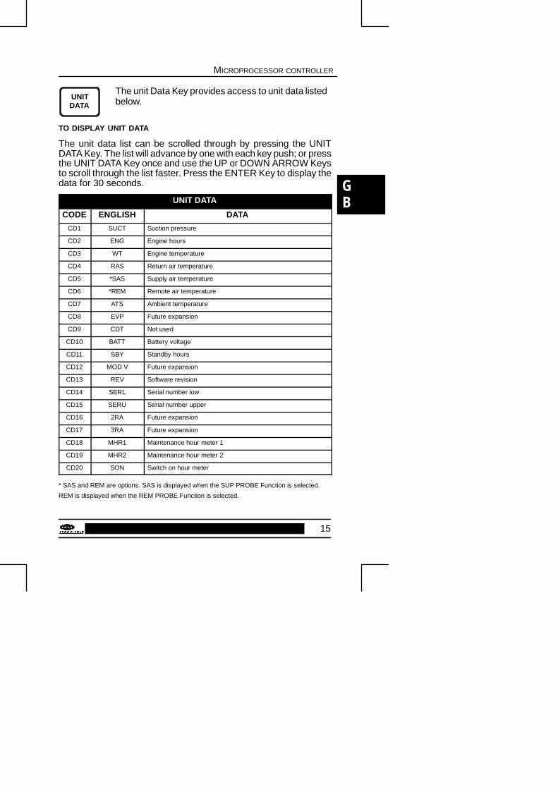
The unit Data Key provides access to unit data listedbelow.
TO DISPLAY UNIT DATA
The unit data list can be scrolled through by pressing the UNITDATA Key. The list will advance by one with each key push; or pressthe UNIT DATA Key once and use the UP or DOWN ARROW Keysto scroll through the list faster. Press the ENTER Key to display thedata for 30 seconds.
UNIT DATA
CODE ENGLISH DATA
CD1 SUCT Suction pressure
CD2 ENG Engine hours
CD3 WT Engine temperature
CD4 RAS Return air temperature
CD5 *SAS Supply air temperature
CD6 *REM Remote air temperature
CD7 ATS Ambient temperature
CD8 EVP Future expansion
CD9 CDT Not used
CD10 BATT Battery voltage
CD11 SBY Standby hours
CD12 MOD V Future expansion
CD13 REV Software revision
CD14 SERL Serial number low
CD15 SERU Serial number upper
CD16 2RA Future expansion
CD17 3RA Future expansion
CD18 MHR1 Maintenance hour meter 1
CD19 MHR2 Maintenance hour meter 2
CD20 SON Switch on hour meter
* SAS and REM are options. SAS is displayed when the SUP PROBE Function is selected.
REM is displayed when the REM PROBE Function is selected.

16
MICROPROCESSOR CONTROLLER
The Function Settings below can be changedthrough the FUNCTION CHANGE key.
TO CHANGE A FUNCTION
WARNING : BEFORE MODIFYING ANY FUNCTION, BEAWARE OF CONSEQUENCES. READ CAREFULLY FUNCTIONPARAMETERS HERE BELOW.
1. Press the FUNCTION CHANGE KEY until the Function youwant change appears on the Display.
2. Press ENTER
3. Press the UP or DOWN ARROW Key until the FunctionSetting you want appears on the Display.
4. Press ENTER
FUNCTION PARAMETERS
CODE ENGLISH AVAILABLE SELECTIONS
FN0 DEFR Defrost interval 1.5, 3, 6, or 12 hr
FN1 ON HIGH AIR High air flow
FN1 OFF NORM AIR Normal air flow
FN2 OFF T Minimum off-time 10,20, 30, 45 or 90 mn
FN3 ON T On-time 4 or 7 min.
FN4 A REM PROBE Controlling Probe-Return air
FN4 B SUP PROBE Controlling Probe-Supply air (above12�C)
FN5 DEGREES�C OR �F
Temperature Unit (�C or �F)

GB
17
MICROPROCESSOR CONTROLLER
FUNCTION PARAMETERS
CODE ENGLISH AVAILABLE SELECTIONS
FN6 ON TIME STRT Maximum Off-time 30 min
FN6 OFF TEMP STRT Temperature based restarting (after minimum Off time)
FN7 MOP STD Not used
FN8 2SET Set-point adjustment 2nd compartment
FN9 3SET Set-point adjustment 3rd compartment
FN10 ON AUTO OP Auto Start operation
FN10OFF MAN OP Manual Start operation
FN11 T RANGE Out-of-Range 2, 3, or 4�C
Code vs English = Code or English Display Format
Manual Glow Override = Normal or Add 30 seconds
Alarm RST = Alarm Reset Required
Alarm CLR = No alarm active

18
MICROPROCESSOR CONTROLLER
PRE-TRIP INSPECTION
The pre--trip inspection should be performed before picking up anyload. This inspection is essential to anticipate and help minimize thepossibility of “over--the--road” problems. These checks take only afew minutes.
1. Place the unit’s main power switch to the Stop position.
2. Fuel -- Drain any water and impurities from the sump of the re-frigeration unit fuel tank by opening the drain--cock located onthe bottom of the tank. Close the valve when only pure fuelemerges. Check the fuel level in the tank, ensuring that the fuelsupply is adequate for unit operation. Refuel if necessary.
3. Belts -- Check the belt tension by depressing the belt with yourthumb, near the center of the longest free run of each belt.Under moderate pressure each belt should deflect approxima-tely 6 mm to 13 mm (1/4 inch to 1/2 inch). If the belts deflectmore than this they should be tightened (loose belts may slip,generating heat and reducing belt life). If the belts are too tightthey should be loosened; tight belts can reduce bearing life.
4. Battery -- On units equipped with serviceable batteries, thelevel of the electrolyte in each of the cells should be checked.If the level is low, distilled water should be added to the correctlevel. Most units, however, are equipped with low or mainte-nance--free batteries; these should be inspected to ensure thatthe connections are clean and tight, and the battery hold--downshould be checked for tightness.

GB
19
MICROPROCESSOR CONTROLLER
5. Engine Oil -- The engine oil should be checked last, since oilhas to drain out of the block and into the oil pan to obtain acorrect reading. Remove the dip--stick (1), wipe it clean andre-insert it fully into the engine block. Once again, remove thedip--stick and observe the oil level; it should be somewherebetween the ”full” and ”add” marks. If it is below the add mark,add oil until the level is correct.
1
6. Coolant level -- Visually inspect the coolant level in thecoolantbottle (located on the upper left-hand side of the unit).
7. Over--all Unit inspection -- Visually inspect the entire unit forleaks, loose bolts, frayed, loose, or broken wires, etc. Theradiator and condenser coils of the unit should be free of dirt,bugs, cardboard, or any other debris that may obstruct airflowacross the coils. The evaporator (located inside the body)should be free of debris also, especially stretch--wrap, whichis often used during transport to prevent cargo from shifting.
8. Truck body -- The body should be inspected prior to loading.Check the door and vent seals for damage and wear. Inspectthe entire interior and exterior of the body to detect any dama-ge, including the inner and outer skins of the body. Damage tothe insulation may compromise the unit’s ability to maintain theproduct temperature by increasing the amount of heat gain inthe box.
9. Pretrip -- Initiate a pretrip by pressing the PRETRIP Key.

20
MICROPROCESSOR CONTROLLER
UNIT OPERATION
STARTING THE UNIT
Complete the Pre-trip inspection described in the previous section.
Road Operation
Place the RUN/STOP (2) switch to the RUN position. If the unit waspreviously operating in STANDBY mode, place the switch to theENGINE position (3). Under normal operating circumstances, thisis all that is required to start the unit. The microprocessor initiatesa unit pretrip check, initiates preheating for a period determined bythe temperature of the engine coolant, and automatically starts theunit.
Standby Operation
Check that the unit is connected to a suitable electricity supply.Place the RUN/STOP (2) switch to the RUN position, and theStandby switch to STANDBY (3). The unit now operates onStandby. See the table on page 52 for information about theappropriate wiring.
MANUAL START
1. Place the switch (2) to RUN to control the unit.
2. Place the unit preheat and manual start switch to mode [dieselengine start-up (MGC)] -- see on Control Relay Box page 14.
GLOW : Preheat
CRANCK : Start-up
UNIT SHUT-DOWN
Place the RUN/STOP (2) switch to the STOP position to shut downthe unit.

GB
21
MICROPROCESSOR CONTROLLER
CHANGING THE SET-POINT
Press the UP ARROW or DOWN ARROW key until the desiredset-point is displayed on the left side of the cab command displaywindow. When the arrow key is released, the set-point will beginflashing, this is a sight that you must press the ENTER key toconfirm the new set-point. Otherwise, the set-point will revert to thepreviously entered set-point.
DEFROST
- Defrost is fully automatic but can be manually initiated if required,as long as the box temperature is equal to or lower than +3�C.
- It is recommended to carry out a defrost cycle one hour afterloading, particularly when transporting goods such as fresh meatetc ...
- The automatic defrost cycle is controlled by an air switch or by adefrost timer (preset 1,5 -- 3 -- 6 and 12 hours) using hot gas fromthe compressor.
- During the defrost cycle, the evaporator fan is stopped.
- Defrost termination is automatically controlled by two “klixon”thermostats.
- During defrost, the Defrost light is On.

22
MICROPROCESSOR CONTROLLER
FAULT ALARM DISPLAY AND SAFETY FEATURES
Display will alternate between an alarm message and the normaldisplay whenever any of the failures listed below occur.
NOTE
Whenever the fault light is on, check display for fault message.Reset the micro to start the unit. Press FUNCTION CHANGE key,the UP/DOWN arrow until ALARM RST is displayed. Press enter toclear alarm. Alarm CLR will now be displayed and unit will restart.Other method to reset : move RUN/STOP switch to STOP. Unitresets and will start when RUN/STOP switch is moved to runposition.
ALARM DISPLAY °= FAULT LIGHT ON
CODE ENGLISH DESCRIPTION
AL0 ENG OIL ° Low Oil Pressure
AL1 ENG HOT ° High coolant Temperature
AL2 HI PRESS ° High Discharge Pressure
AL3 START FAIL ° Start failure
AL4 LOW BATT ° Low battery voltage
AL5 HI BATT ° High battery voltage
AL6 DEFRFAIL Defrost Override
AL7 ALT AUX ° No Alternator Auxiliary Output
AL8 STARTER ° Starter Motor Fault
AL9 RA SENSOR ° Return Air Sensor Fault
AL10 SA SENSOR Supply Air Sensor Fault
AL11 WT SENSOR Coolant temperature sensor
GB
23
MICROPROCESSOR CONTROLLER
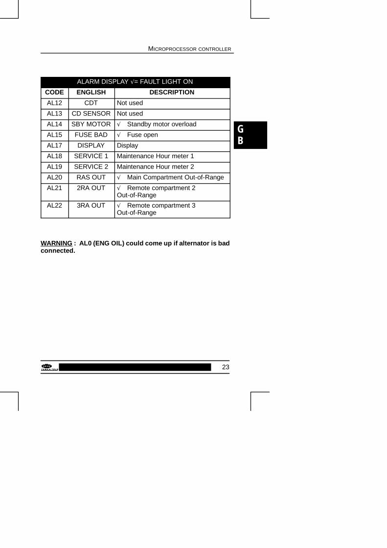
ALARM DISPLAY °= FAULT LIGHT ON
CODE ENGLISH DESCRIPTION
AL12 CDT Not used
AL13 CD SENSOR Not used
AL14 SBY MOTOR ° Standby motor overload
AL15 FUSE BAD ° Fuse open
AL17 DISPLAY Display
AL18 SERVICE 1 Maintenance Hour meter 1
AL19 SERVICE 2 Maintenance Hour meter 2
AL20 RAS OUT ° Main Compartment Out-of-Range
AL21 2RA OUT ° Remote compartment 2Out-of-Range
AL22 3RA OUT ° Remote compartment 3Out-of-Range
WARNING : AL0 (ENG OIL) could come up if alternator is badconnected.

24
MICROPROCESSOR CONTROLLER
FUSES
The fuses which protect the circuits of the control system arelocated in the box on the left-hand side of the unit.
The fuses are accessed by opening the door (2 screws) and thenthe control box panel (2 screws).
F9F8
F6F5F4F3
F10
Designation Power (Amps)
F1 Main fuse 80 A
F2 Fuel heater fuse (option) 20 A
F3 Road / Standby fuse 25 A
F4 Solenoïd fuse 15 A
F5 Auto/Start and Out-of-Range fuse 7.5 A
F6 Fault light fuse 5 A
F8 Phase detector fuse 1 A
F9 Microprocessor fuse 5 A
F10 Water pump fuse 5 A

GB
25
SOLID STATE CONTROLLER
DESCRIPTION
16
15
1413
12
11
10
9
876
345
2
1
17

26
SOLID STATE CONTROLLER
CONTROL PANEL FUNCTIONS
1. Standby hourmeterFor maintenance purposes, indicates thenumber of operating hours of the electricmotor.
2.+ --
Battery charge ammeter
3. Malfunction lightLights up in the event of a start--up problemin Start/Stop mode.
4. Standby operation light
5.
DEFROST
Defrost lightLights up when the unit is in defrost mode,enabling the ice which has formed on theevaporator coil to melt.
6.
HEAT
Heating mode lightLights up when the unit is in heat mode. Thebox temperature rises to reach the requiredset--point temperature, if set--point is equalto or greater than --12�C (10�F).
7.
COOL
Cooling mode lightLights up on the control panel when the unitis in cool mode. The box temperature pullsdown to set--point.

GB
27
SOLID STATE CONTROLLER
8. ENGINEAUTOSTART Auto- Start light
Lights up when the unit is in Start--Stopmode.
9.
BOX TEMPERATURE
Box temperature display
10. Diesel engine hourmeterFor maintenance purposes, indicates thenumber of operating hours for the dieselengine.
11. Temperature switch
The temperature selector enables selection of the set--point atwhich the cargo is to be maintained. Just turn the selector until thearrow indicates the required temperature.
12. SAS
RAS
Supply air temperature sensor (SAS)
Return air temperature sensor (RAS)
13. Defrost/Glow switchWhen the switch is held in the UP position,this indicates that the engine glow plugs areenergized : this enables the combustionchamber to reach a sufficiently hightemperature for the fuel to ignite when thestarter operates.When the switch is held in the Downposition, the unit switches to Defrost mode(when the evaporator temperature issufficiently low).

28
SOLID STATE CONTROLLER
14.
RUN
STOP
Start/Run/Stop switchWhen the switch is held in the UP position,this actuates the starter.When released the switch moves to thecentral position (RUN). In this position theunit operates in Road or Standby modedepending on the mode selected with theRoad/Standby switch (15).
15. Road/Standby switchWhen the switch is held in Down position,the unit operates in Road (diesel engine)mode.When the switch is held in the UP position,the unit operates in Standby (electric motor)mode. For this latter mode, the unit must beconnected to the proper power network.
16.
NORMAL
Start/StopFor automatic operation, place the switch inthe UP position. Pilot light (8) lights up.For continuous run in diesel engine orelectric drive, place the switch on NORMAL.
17. Unit ResetPush to reset the control circuit.

GB
29
SOLID STATE CONTROLLER
CONTROL RELAY BOX
Located on the left-hand side of the unit.
30
SOLID STATE CONTROLLER
PRE-TRIP INSPECTION
The pre--trip inspection should be performed before picking up anyload. This inspection is essential to anticipate and help minimize thepossibility of “over--the--road” problems. These checks take only afew minutes.
1. Place the unit’s main power switch to the Stop position.
2. Fuel -- Drain any water and impurities from the sump of therefrigeration unit fuel tank by opening the drain--cock locatedon the bottom of the tank. Close the valve when only pure fuelemerges. Check the fuel level in the tank, ensuring that the fuelsupply is adequate for unit operation. Refuel if necessary.
3. Belts -- Check the belt tension by depressing the belt with yourthumb, near the center of the longest free run of each belt.Under moderate pressure each belt should deflect approxima-tely 6 mm to 13 mm (1/4 inch to 1/2 inch). If the belts deflectmore than this they should be tightened (loose belts may slip,generating heat and reducing belt life). If the belts are too tightthey should be loosened; tight belts can reduce bearing life.
4. Battery -- On units equipped with serviceable batteries, thelevel of the electrolyte in each of the cells should be checked.If the level is low, distilled water should be added to the correctlevel. Most units, however, are equipped with low or mainte-nance--free batteries; these should be inspected to ensure thatthe connections are clean and tight, and the battery hold--downshould be checked for tightness.

GB
31
SOLID STATE CONTROLLER
5. Engine Oil -- The engine oil should be checked last, since oilhas to drain out of the block and into the oil pan to obtain acorrect reading. Remove the dip--stick (1), wipe it clean andre--insert it fully into the engine block. Once again, remove thedip--stick and observe the oil level; it should be somewherebetween the ”full” and ”add” marks. If it is below the add mark,add oil until the level is correct.
1
6. Coolant level -- Visually inspect the coolant level in thecoolantbottle (located on the upper left-hand side of the unit).
7. Over--all Unit inspection -- Visually inspect the entire unit forleaks, loose bolts, frayed, loose, or broken wires, etc. Theradiator and condenser coils of the unit should be free of dirt,bugs, cardboard, or any other debris that may obstruct airflowacross the coils. The evaporator (located inside the body)should be free of debris also, especially stretch--wrap, whichis often used during transport to prevent cargo from shifting.
8. Truck body -- The body should be inspected prior to loading.Check the door and vent seals for damage and wear. Inspectthe entire interior and exterior of the body to detect any dama-ge, including the inner and outer skins of the body. Damage tothe insulation may compromise the unit’s ability to maintain theproduct temperature by increasing the amount of heat gain inthe box.

32
SOLID STATE CONTROLLER
UNIT OPERATION
- The operation of this self--contained unit is automatic.
- During temperature pulldown, the diesel engine operates at highspeed.
ROAD OPERATION
Before starting-up :
- Set the thermostat (11) to the requisite temperature.
- Set sensor (12) to RAS for a negative temperature, or to SAS fora positive temperature.
Start-up without the start/stop system :
- Check that switch (16) is the “NORMAL” position.
- Place switch (15) in the Road position .
- Place switch (14) on RUN (central position).
- Preheat for approximately 30 seconds by holding switch (13) in
the UP position on Glow .
- Start unit by placing switch (14) in the position (while holding
switch (13) in the glow position .
- After starting the engine, release switch (14) and hold switch (13)in the UP position for a few seconds longer.

GB
33
SOLID STATE CONTROLLER
- Check that the pilot lights come on as follows :� Cool : 7� Heat : 6� Defrost : 6 and 5
Start-up with the start/stop system :
- Place switch (15) in the Road position
- Place switch (16) in the UP position
- Place the switch (14) on “RUN” (middle position), the Auto-Start(8) goes on.The unit automatically preheats and starts.
- Check that the ammeter (2) indicates the battery charge.
- Check that the following lights are On :� Cooling : 7� Heating : 6� Defrost : 6 and 5
- The alarm light (3) goes on if a start-up problem occurs (seeinstruction decal on control box).
If the alarm light goes On, place the ON/OFF switch to the Stopposition and repeat the whole operation. If the malfunction persists,the unit will try to start up three times and then will shut downcompletely. The alarm light will go On once again. Place the switchto the Manual position, and follow the procedure indicated in thesection above entitle “Start-up without the Start/Stop system”.
If there is any difficulty in starting-up, check that :
- Preheating is sufficient.
- The Preheat switch (13) remains in the Up position duringstart-up.
- The unit is correctly supplied with fuel.

34
SOLID STATE CONTROLLER
Shutting-down the unit :
- Place switch (14) in the “STOP” position.
STANDBY OPERATION
Start-up :
- Check the type of three-phase current and power output available(see the table on page 52).
- Connect the unit to the power network.
- Place switch (15) in the Standby position .
- Start the unit up by placing switch (14) in the RUN (centralposition).
- The unit is fitted with a phase detector which inhibits enginestart-up if the phases are reversed. In the latter case an alarmsounds. Place the RUN/STOP switch in the STOP position.Disconnect the power plug and switch the phases in the socketusing a screwdriver.
If you have any difficulty in starting-up the unit, check :
- That the box temperature (9) is not equal to set-point.
- That time-delayed temperature regulation is not On, by actuatingthermostat (11) and stopping the unit using switch (14) to cancelthe time-delay.
- That the three-phase power supply and voltage are correct.
- That the fuses have not blown in the control box.

GB
35
SOLID STATE CONTROLLER
UNIT SHUT-DOWN
Place the RUN/STOP switch (14) in the STOP position to shut downthe unit.
WARNING
NEVER DISCONNECT THE EXTENSION CORD WITHOUTPLACING SWITCH (14) IN THE STOP POSITION.
DEFROST
- Defrost is fully automatic but can be manually controlled ifrequired, as long as the box temperature is equal to or lower than+3�C.
- It is recommended to carry out a defrost cycle one hour afterloading, particularly when transporting goods such as fresh meatetc ...
- The automatic defrost cycle is controlled by an air switch using hotgas from the engine.
- During the defrost cycle, the evaporator fan is stopped.
- Defrost termination is automatically controlled by two “klixon”thermostats.
- During defrost, the Defrost light is On.
HEATING
In Road mode (Engine operation)
- Heating is controlled by the thermostat.
- Heating takes place in high-and low-speed heat modes.
- Temperature regulation takes places in high-and low-speed heatmodes.
In Standby mode (Electric operation)
- Temperature regulation is obtained by the unit cycling off when theset-point has been reached.

36
SOLID STATE CONTROLLER
START/STOP SYSTEM(OPTION FOR ELECTROMECHANICAL) :
The system works as follows :
- Engine preheat and start-up is automatic.
- When the temperature selected with the thermostat has beenreached, the system shuts the diesel engine down.
- Engine shut-downs can be programmed to last 15, 30 or60 minutes. Shut-down times will be modified depending on theisothermal insulation of the box, the ambient temperature and thecargo. The shut-down time is pre-programmed in the plant to15 minutes. The user should determine whether this setting isappropriate for his type of cargo and the insulation of thebodywork (all adjustments are to be made by a Carrier Transicoldtechnician).
Caution : During unit shut-downs, the evaporator fans also stop.Only use this operating mode for products which tolerateshut-downs of this kind.
- At the end of the programmed shut-down time, if the boxtemperature is more than 1,7�C outside the set-point range, thesystem restarts the engine for a minimum of 10 minutes.
- The start/stop system comprises several safety devices whichensure it operates correctly. These check :� the battery status,� the temperature of the engine water,� the minimum run time.

GB
37
SOLID STATE CONTROLLER
TEMPERATURE REGULATION
In Road mode (Engine operation)
- Down to --12�C, the box temperature is regulated in low-speedheat and low-speed cool; under --12�C, a safety cut-out preventsany possibility of heating: this means that as soon as the set-pointtemperature has been reached the unit will operate in low speedcool.
- The continuous operation of the fans even during temperatureregulation ensures a precise, uniform temperature of the cargotransported.
In Standby mode
- Temperature regulation is obtained by the unit cycling off when theset-point has been reached.

38
SOLID STATE CONTROLLER
FUSES
The fuses which protect the circuits of the control system arelocated in the box on the left-hand side of the unit.
The fuses are accessed by opening the door (2 screws) and thenthe control box panel (3 screws).
F2 F3 F4 F5 F7

GB
39
SOLID STATE CONTROLLER
Designation Power (Amps)
F1 Main fuse 20 A
F2 Road/Standby fuse 7,5 A
F3 Speed/Clutch/Hot gas solenoid fuse 15 A
F4 Fuel pump fuse 5 A
F5 Water pump fuse 5 A
F7 Fuel heater fuse (option) 25 A
F8 Phase detector fuse (not shown) 1 A
RR Run relay
SR Speed relay
HR Heat relay
GPR Glow plug relay
RA Run solenoid
SBR Standby relay
BPR By-pass relay
DRO Defrost time relay
BPR Fuel Heater relay (option)
RALT Alternator relay
ASR Alternator starter relay

40
TROUBLESHOOTING
Everything possible has been done to ensure that your unit is themost reliable, trouble--free equipment available on the markettoday. If, however, you run into problems, the following section maybe of assistance.
If you do not find the trouble that you have experienced listed below,please call your Carrier Transicold dealer for assistance.
General Problems
UNIT WON’T CRANK, BY THE STARTER CHECK BATTERY CONDITION.
CHECK BATTERY CONNECTIONS.
CHECK ALL FUSES.
CHECK RESET BUTTON
(ELECTROMECHANICAL)
CHECK ALTERNATOR CONNECTIONS.
UNIT WON’T START CHECK FUEL LEVEL.
CHECK ALL FUSES.
UNIT WON’T RUN CHECK FUEL LEVEL.
CHECK ENGINE OIL LEVEL.
UNIT DIES CHECK BELTS.
CHECK ENGINE OIL LEVEL.
CHECK COOLANT LEVEL.
CHECK FUEL LEVEL.
CHECK ALL FUSES.
UNIT NOT COOLING PROPERLY DEFROST UNIT.
CHECK EVAPORATOR FOR AIRFLOW
RESTRICTION.
CHECK CONDENSER FOR AIRFLOW
RESTRICTION.
CHECK BODY FOR DAMAGE OR AIR
LEAKS.
GB
41
UNIT MAINTENANCE
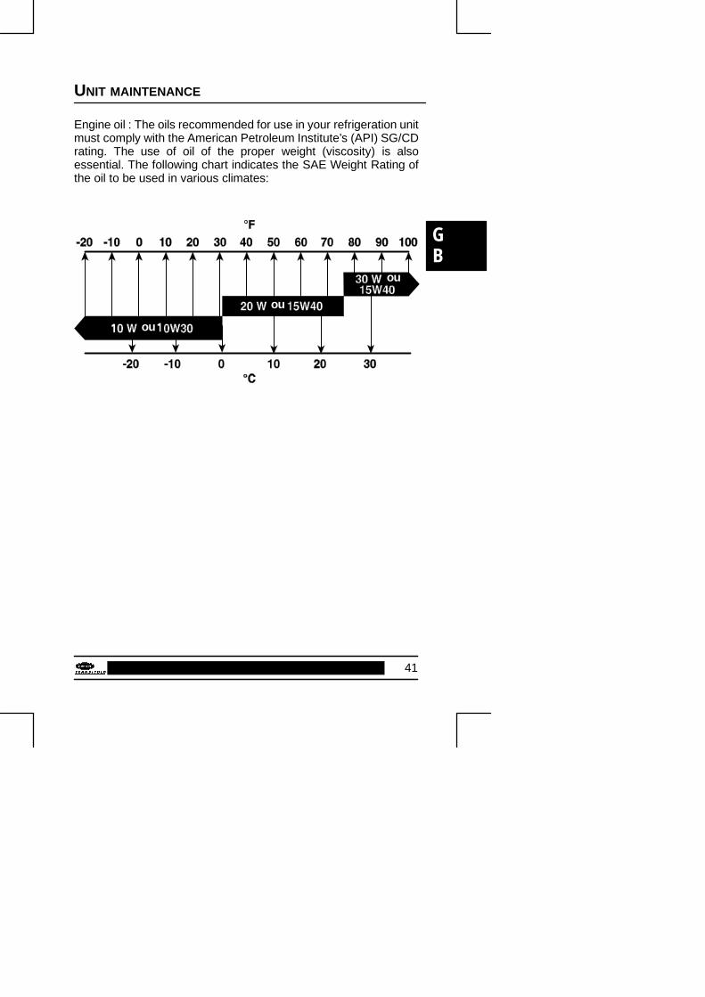
Engine oil : The oils recommended for use in your refrigeration unitmust comply with the American Petroleum Institute’s (API) SG/CDrating. The use of oil of the proper weight (viscosity) is alsoessential. The following chart indicates the SAE Weight Rating ofthe oil to be used in various climates:
ou
ou
ou

42
UNIT MAINTENANCE
The following oils are accepted for use in Europe with theMaxima 2 unit.
RECOMMENDED OILS
CARRIERAGIPANTARBP
ELF
FIATFINA
HAFA
IGOL
IMPERATORLABOMOBIL
OPALORLYPOLAROILRENAULT
TEXACOTOTALSHELL
UNIL
YACCO
CARRIER TD+15W--40
SIGMA TURBO SHPD 15W--40
GRAPHITE R 15W--40
VANELLUS C3 EXTRA 15W--40
VANELLUS FE 15W30
MULTIPERFORMANCE4D 15W--40
PERFORMANCE TROPHY 15W--40
URANIA TURBO 15W--40
KAPPA LDO 15W--40
KAPPA TD PLUS 15W--40
KAPPA EXTRA 15W--40
DETERGENTE 4DM 15W--40
STRADEX 900 ECO 15W--40
SYNTHIDEX ECO 15W--40
RALLYE TURBO 4E 15W--40
RALLYE TURBO 4E LD 15W--40
RAFF SUPER HPDO 15W--40
MEGAMAXI 15W--40
DELVAC SHC 15W--40
DELVAC 1400 SUPEROPALGET D 500 15W--40
TURBO 2002 15W--40
POLATRUCK 15W--40
KMX 2 PLUS 15W--30
KMX 2 PLUS 15W--40
MV5 “EUROPE”
URSA SUPER TD 15W--40
RUBIA TIR MAX 15W40
MYRINA TX 15W--40
MYRINA T 15W--30
SUPER ROC 3D 15W--40
TURBO DX 15W--40
SM 4D + 15W--40
The above oil equivalents are based on the recommendationscontained in the suppliers’s technical literature.

GB
43
UNIT MAINTENANCE
In addition to the above service requirements, please adhere to thefollowing :
The engine oil should be changed at least once per year, even if theengine has not run the necessary number of hours.
The coolant (anti-freeze should be replaced after a maximum of twoyears.
UNIT MAINTENANCE SCHEDULE
For the most reliable operation and for maximum life, your unitrequires regular maintenance. This includes oil and filter changes,fuel and air filter replacement, coolant replacement, belts etc...
The maintenance should be performed on the following schedule:
MAXIMA 2 Required Service
With Bypass
Oil filters
A A AB
AC
AB
A ABC
A
Hours 400 1500 3000 4500 6000 7500 9000 10500
These maintenance schedules are based on the use of approvedoils and regular pre-trip inspections of the unit.
Descriptions of the type of service required are found on the nextpage.

44
UNIT MAINTENANCE
DESCRIPTION OF SERVICE OPERATIONS
Service Operations
Service A
Drain engine oil and change oil air filter.
Grease control rods of diesel engine.
Replace oil filter cartridge and by--pass filter cartridge.
Replace primary and secondary fuel cartridge.
Clean fuel pump filter.
Check level of coolant, refrigerant and battery electrolyte.
Drain water in fuel tank.
Check alternator charge.
Check thermostat operation.
Check manual/automatic defrost operation.
Check operation of solenoid.
Check “klixon” cut--out.
Check drainage of defrost water.
Check motor speed in high--speed/low--speed.
Check bolts/screws are correctly tightened.
Check unit fastening into box.
Check belts and belt tighteners.
Check pilot lights and switches.
Check tightness of lines and connections.
Check relays, electrical connections and hoses.
Clean condenser and radiator.
Service B
Grease blower and hinges.
Replace belts.
Check and adjust rocker arms.
Service C
Replace bearings and brushes of 12 VDC alternator.
Check and adjust clutch.
Calibrate injectors 140 kg/cm3.
GB
45
UNIT MAINTENANCE
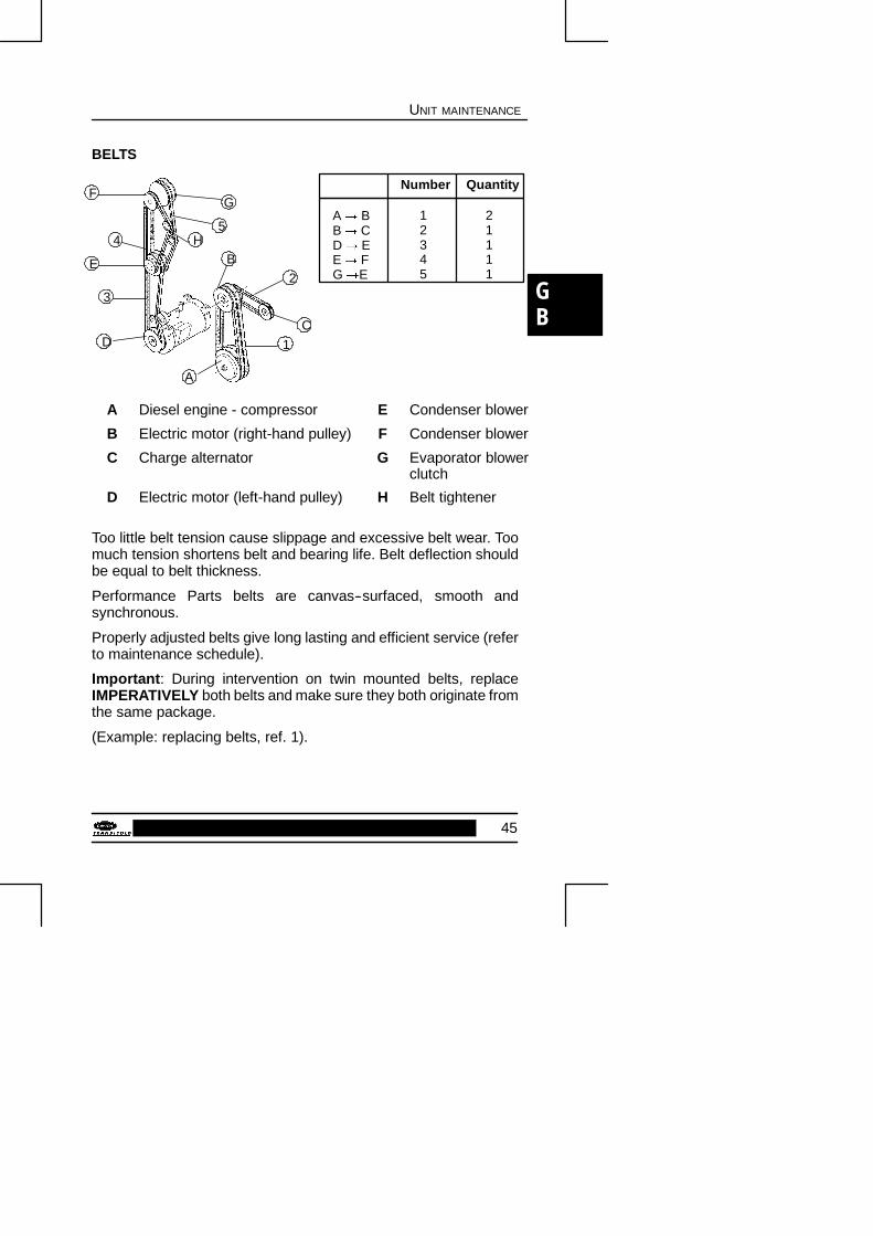
BELTS
Number Quantity
12345
A� BB� CD� EE� FG�E
21111
4
E
3
D
A
1
C
2
BH
5
GF
A Diesel engine - compressor E Condenser blower
B Electric motor (right-hand pulley) F Condenser blower
C Charge alternator G Evaporator blowerclutch
D Electric motor (left-hand pulley) H Belt tightener
Too little belt tension cause slippage and excessive belt wear. Toomuch tension shortens belt and bearing life. Belt deflection shouldbe equal to belt thickness.
Performance Parts belts are canvas--surfaced, smooth andsynchronous.
Properly adjusted belts give long lasting and efficient service (referto maintenance schedule).
Important: During intervention on twin mounted belts, replaceIMPERATIVELY both belts and make sure they both originate fromthe same package.
(Example: replacing belts, ref. 1).

46
UNIT MAINTENANCE
REPLACING BELTS
- Remove belt 3, untighten the tensioners of the electric motor.
Replace the belts (1 and 2) coupling the compressor motor to theelectric motor:
- Untighten the 6 screws of the plate (C) on the motor flywheel.
- Push the plate towards the compressor in the direction of thearrow (fig. 2).
- Change the belts in the space thus obtained.
A = Engine
B = Compressor
C = Flywheel plate
� �
$
&
%
19mm

GB
47
UNIT MAINTENANCE
FILTERS
2
3
1
Rep. Designation1 Oil filter
2 By-pass oil filter
3 Fuel filter
4 Oil bath air cleaner 4
For code numbers consult the corresponding spare parts manual.

48
PRODUCT LOADING
Proper air circulation in the truck body, air that can move around andthrough the load, is a critical element in maintaining product qualityduring transport. If air cannot circulate completely around the load,hot spots or top--freeze can occur.
The use of pallets is highly recommended. Pallets, when loaded soair can flow freely through the pallets to return to the evaporator,help protect the product from heat passing through the floor of thetrailer. When using pallets, it is important to refrain from stackingextra boxes on the floor at the rear of the trailer, because this will cutoff the airflow.
Product stacking is another important factor in protecting theproduct. Products that generate heat, fruits and vegetables forexample, should be stacked so the air can flow through the productto remove the heat; this is called “air stacking” the product. Productsthat do not create heat, meats and frozen products, should bestacked tightly in the center of the trailer. All products should be keptaway from the sidewalls of the body, allowing air to flow between thebody and the load; this prevents heat filtering through the walls fromaffecting the product.
It is important to check the temperature of the product being loadedto ensure that it is at the correct temperature for transport. Therefrigeration unit is designed to maintain the temperature of theproduct at the temperature at which it was loaded; it was notdesigned to cool a warm product.
OPTIONS FOR INSULATED BODIES
- Mobile partition
The mobile partition must be placed at a minimum distance of4000 mm from the evaporator.
- Ducting of evaporator air outlet. Ventilation ducts mustnever be covered.

GB
49
PRODUCT LOADING
SOME ADVICE
Before loading
- Pre--cool the inside of the insulated body by lowering thetemperature for about 15 minutes.
- Remove the humidity inside the body by defrosting manually. Thiscan be done only when the inside temperature is 3�C or less.
When loading
- This is to be carried out with the unit stopped.
- It is recommended to open doors as little as possible to avoid theintake of hot air and humidity.
- Select the temperature using the thermostat in accordance withthe goods transported.
- Check the internal temperature of the goods being loaded (usinga probe thermometer).
- Take care not to obstruct the air intakes on the evaporator sectionand the ventilation ducts.
- Leave a free space of about:� 6 to 8 cm between load and frontwall,� 20 cm between the top of the load and the roof,� between the floor and the load (gratings, pallets).
- Do not forget to close the rear ventilation flaps.
- Before closing the doors, check your load once more and see thatnobody is shut inside the trailor.
50
PRODUCT LOADING
NOTE
If used stationary, it is recommended to place the box in the shade.
Important :
Never leave your unit too long without operating.

GB
51
RECOMMENDED TRANSPORT TEMPERATURES
Below are some general recommendations on product transporttemperatures and operating modes for the unit. These are includedfor reference only and should not be considered preemptive of theset--point required by the shipper or receiver.
More detailed information can be obtained from your CarrierTransicold dealer.
Product Set-point Operating Mode*
Bananas 15�C Continuous
Fresh fruits andvegetables
���C to +6�C Continuous
Fresh fish underbed of ice recom-mended
+2�C Auto-Start/Stop
Fresh meat ���C Auto-Start/Stop
Fresh seafood ���C Auto-Start/Stop
or continuous
Dairy products +2�C to +6�C Auto-Start/Stop
or continuous
Block of ice --���C to --12�C Auto-Start/Stop
Frozen fruits andvegetables
--25�C Auto-Start/Stop
Frozen meats andseafood
--25�C Auto-Start/Stop
Ice cream --29�C Auto-Start/Stop
* During delivery cycles that include frequent stops and dooropenings, it is recommended that the unit always be operated in thecontinuous run mode to help ensure product quality. It isrecommended to shut down the unit during the periods when thebody doors are open, in order to maintain the correct temperatureof the cargo.

52
STANDBY OPERATION GUIDELINES
For safe, reliable operation in Standby mode, it is important toconsider the following guidelines:
- Never plug the unit in to the power source with the main switch inthe RUN position. The main switch should always be in the STOPposition when connecting the unit to the power source.
- The extension cord (max. length 8 m) and fuses used to connectthe unit to the power network must comply with the following tableand the legislation currently applicable in the place of work:
Unit aM200/240/3/
50 Hz
aM350/415/3/
50 Hz
Standardized extension cableH.070RNF
Maxima 2 50 A 30 A220 Volts 380 Volts
Maxima 2 50 A 30 A10 mm2 6 mm2
aM: Motor starting fuse.
The unit connection cable must be fitted with a ground connection.The cable must be connected to earth.
Recommendation: On a three--phase network, use a differentialprotection for each plug.
Before performing maintenance operations on the refrigeration unit,check it is disconnected from the power supply, that the main switchis in the STOP position, and that the unit can not restartautomatically during the operation.
Operations on the 220V or 380V supply for the unit must only becarried out by authorized personnel.
Note: If operating on a 220V supply, check that the unit is correctlyfitted with the suitable plug and overload relay.
The user is liable for ensuring that the above measures are taken.
GB
53
MANUFACTURER INFORMATION
WARRANTY
Always update the service chart which is to be found inside the frontcover.
This manual refers to the standard model.
Some options may not appear in it, and in such cases you arerequested to consult our Technical Services.
Carrier Transicold constantly seeks to improve the quality of itsproducts and therefore reserves the right to modify them withoutprior notice.
INSTALLATION
During assembly and routine service operations.
Access to the unit located on the bulkhead of the semi--trailer mayinvolve certain risks.
TAKE EVERY SAFETY MEASURE WHEN ACCESSING THEUNIT (e.g.: standard ladders, running board with railing, safety beltetc.)
Installation of this unit requires no special knowledge ofrefrigeration. To fit the unit onto the vehicle body, simply slide theevaporator unit into the opening in the front panel, and secure usingthe bolts/screws provided.
Advice :
When handling the unit, use suitable lifting gear and the lifting hookssupplied with the installation package; remove the hooks once theunit has been installed.
Note:
The unit should not protrude out of the body.
BATTERY
Maintenance :
Never leave a unit more than a month without running it. In the caseof a long standstill, charge the battery independently.

54
MANUFACTURER INFORMATION
Before performing any welding on the chassis, make sure thebattery of the vehicle and the alternator, and all other electronicsystems (microprocessor) are disconnected.
Never try to start the vehicle with a booster: this can damage theelectronic components in the unit or on the vehicle.
SAFETY INSTRUCTIONS
1. Check that all mounting bolts are well tightened and suitablefor use.
2. When you drill holes in the unit or in the body of the vehicle, becareful not to pierce the refrigeration tubes or the electricalwiring.
3. When you are working next to the batteries (condenser andevaporator) be careful not to cut yourself on the sharp edges.
4. When the unit is running, keep your hands away from belts andfan motors.
5. Never close the discharge valves of the compressor when theunit is running.
6. In case of repair, only use manometer by--pass hoses whichare in a good condition and avoid any contact with belts, pulleyor fans.
7. The refrigerant liquid must be handled with great care.
8. Next to a flame the refrigerant liquid gives off a phosgene gaswhich has an unpleasant smell and irritates the lungs.
9. Never use a flame to heat up a closed cooling circuit.
10. The cooling system must be handled with great care. Whenliquid refrigerant enters the atmosphere, it evaporates andfreezes everything it contacts.

GB
55
MANUFACTURER INFORMATION
First aid in case of frost--bite:
a) Cover up the frost--bitten part.
b) Quickly warm up the frost--bitten part by dipping it into lukewarmwater (not hot).
c) If you do not have water, wrap the injured part in a clean cloth.
d) If refrigerant fluid has been splashed into your eyes, rinse themimmediately with clean water; as a precaution, you arerecommended to have a medical examination as well.
11. Cooling oil
Synthetic types
- Avoid prolonged or repeated contact with the skin.
- Wash carefully after handling.
REMARKS ABOUT SAFETY
“Low pollution” engine
The TRIVORTEX--type indirect injection system minimizes exhaustfume pollution.
NEVER START THE ENGINE IN A CLOSED ROOM, EXHAUSTGAS IS POISONOUS.
It is colorless and odorless and created by the incompletecombustion of hydrocarbons.
Exhaust gas is poisonous; breathing it in induces drowsinessand may lead to loss of consciousness.
The following symptoms indicate exhaust gas has been inhaled:
- Blackout
- Intense headache
- Sudden weakness and sleepiness
- Vomiting
- Muscular contractions
- Beating temples

56
MANUFACTURER INFORMATION
If you feel one of the above mentioned symptoms, go out andbreathe fresh air.
Maintenance operations should be done at the recommendedintervals on your equipment. Check the exhaust gas system toavoid gas inhalation.
If you notice a noise or modification of the exhaust systemimmediately stop the engine and call your sales service center forchecking and repair.
WARNING :
The unit starts automatically: keep away from belts, pulleys andfans.

GB
57
“ A.T.P. EUROPE” REGULATION EXTRACT
(Date: March 1974)
Approval of vehicles intended for the carriage of perishable goods.
Before putting a refrigerated vehicle into service, it is necessary tohave it approved by the Regional Health Department.
CHARACTERISTICS OF VEHICLES USED FOR CARRYINGPERISHABLE GOODS; REFRIGERATION UNIT.
The refrigeration unit is an insulated unit with a cooling systemwhich makes it possible, with a mean outside temperature of +30�C,to lower the temperature inside the empty body and to maintain thislow temperature in the following way:
CLASS A
Refrigeration unit furnished with a cooling system whereby atemperature between +12�C and 0�C inclusive can be chosen.
CLASS B
Refrigeration unit furnished with a cooling system whereby atemperature between +12�C and --10�C inclusive can be chosen.
CLASS C
Refrigeration unit furnished with a cooling system whereby atemperature between +12�C and --20�C inclusive can be chosen.
The cooling capacity of a unit is determined by a test carried out inone of the approved testing stations and ratified by an official report.
Note: The “K” factor of bodies intended to be classified as C mustbe equal to or lower than 0.4 W/m2 �C.

58
“A.T.P. EUROPE” REGULATIONS EXTRACT
SIGNS, IDENTIFICATION MARKS AND PLATES TO BEATTACHED TO REFRIGERATION UNITS
Refrigeration Plate
This reference must be followed by identification marks accordingto the following list:
Standard refrigeration unit Class A FNA
Reinforced refrigeration unit Class A FRA
Reinforced refrigeration unit Class B FRB
Reinforced refrigeration unit Class C FRC
In addition to the above identification marks, the date (month andyear) of expiry of the approval certificate must be indicated.
Example:
FRC
7--1997
(7 = month (June) 1997 = year)
Very important
Regularly check the expiry date of the approval certificate. Duringtransport, the approval certificate or provisional certificate should beshown on request of qualified agents. To have an insulated unitapproved as a refrigeration unit, an application to modify theapproval certificate should be sent to the regional health office.

GB
59
EMERGENCY ROAD SERVICE
At Carrier Transicold we’re working hard to give you completeservice when and where you need it. That implies a worldwidenetwork of dealers and an available emergency service. Theseservice centers are manned by factory--trained service personneland backed by extensive parts inventories to ensure you of promptrepair.
Should you encounter a unit problem with your refrigeration unitduring transit, follow your company’s emergency procedure orcontact the nearest Carrier Transicold service center. Consult thedirectory to locate the service center nearest you. This directorymay be obtained from your Carrier Transicold dealer.
If you are unable to reach a service center, call Carrier Transicold’s24--hour Action Line;
In Europe, call +33 (0)2.35.79.12.12 for 24--hour assistance.
When calling, please have the following information ready forfastest service:
- Your name, the name of your company, and your location.
- A telephone number where you can be called back.
- Refrigeration unit model number and serial number.
- Box temperature, set--point and product.
- Brief description of the problem you are having, and what youhave already done to correct the problem.
We will do everything we can to get your problem taken care of andget you back on the road.