maverick ii™ catalog 250-3 commercial packaged rooftop...
TRANSCRIPT

Engineered for flexibility and performance™
Maverick II™ Catalog 250-3Commercial Packaged Rooftop Systems
Heating & CoolingModels MPS020E – 075E20 to 75 TonsR-410A Refrigerant
Contents
Introduction . . . . . . . . . . . . . . . . . . . . . . . . . . . . . . . 3The HVAC Solution for Low Rise Buildings . . . . . 3
Agency Listed . . . . . . . . . . . . . . . . . . . . . . . . . 3Nomenclature (MPS 020E – 050E). . . . . . . . . 3Nomenclature (MPS 062E – 075E). . . . . . . . . 3
MPS 020E – 050E Features and Options . . . . . . 4MPS 020E – 050E Features and Options(continued) . . . . . . . . . . . . . . . . . . . . . . . . . . . . . . 5MPS 062E – 075E Features and Options . . . . . . 6MPS 062E – 075E Features and Options(continued) . . . . . . . . . . . . . . . . . . . . . . . . . . . . . . 7
Features and Benefits . . . . . . . . . . . . . . . . . . . . . . . 8Why Choose McQuay Rooftop Systems? . . . . . . 8
High Efficiencies and Competitively Priced. . . 8Today’s Solution for 2010 Efficiency andEnvironmental Requirements . . . . . . . . . . . . . 8All-Aluminum Condensers Resist Corrosion . . 8Easy, Low Cost Installation, Maintenanceand Service . . . . . . . . . . . . . . . . . . . . . . . . . . . 9
Unit Construction . . . . . . . . . . . . . . . . . . . . . . . . . 9Controls. . . . . . . . . . . . . . . . . . . . . . . . . . . . . . 9Variable Air Volume Control . . . . . . . . . . . . . 10Electrical . . . . . . . . . . . . . . . . . . . . . . . . . . . . 10Supply Fan Section . . . . . . . . . . . . . . . . . . . . 10Gas Heat Option . . . . . . . . . . . . . . . . . . . . . . 11Electric Heat Option . . . . . . . . . . . . . . . . . . . 12Hot Water Heat Option . . . . . . . . . . . . . . . . . 12Outside Air Options . . . . . . . . . . . . . . . . . . . . 12Condensing Section . . . . . . . . . . . . . . . . . . . 12Cooling Coil/Drain Pan Section. . . . . . . . . . . 13Filter Section . . . . . . . . . . . . . . . . . . . . . . . . . 13Roof Curbs . . . . . . . . . . . . . . . . . . . . . . . . . . 13
MicroTech Unit Controls. . . . . . . . . . . . . . . . . . . . 14Superior Performance and Easy Integration . . . 14
Open Choices™ Feature . . . . . . . . . . . . . . . 14DDC Unit Controller . . . . . . . . . . . . . . . . . . . 14Communication Modules. . . . . . . . . . . . . . . . 14Keypad/Display . . . . . . . . . . . . . . . . . . . . . . . 14Unit Sensors . . . . . . . . . . . . . . . . . . . . . . . . . 14Stand-Alone Controller Features. . . . . . . . . . 15Standard Control Options . . . . . . . . . . . . . . . 16Compressor Control . . . . . . . . . . . . . . . . . . . 16Supply Fan Control . . . . . . . . . . . . . . . . . . . . 17Economizer Control. . . . . . . . . . . . . . . . . . . . 17Exhaust Fan Control . . . . . . . . . . . . . . . . . . . 17Field Output Signals . . . . . . . . . . . . . . . . . . . 17Alarm Management and Control . . . . . . . . . . 18
Application Considerations . . . . . . . . . . . . . . . . . 19General Rooftop Applications . . . . . . . . . . . . . . 19
Unit Location . . . . . . . . . . . . . . . . . . . . . . . . . 19Service Clearance. . . . . . . . . . . . . . . . . . . . . 19Curb Installation . . . . . . . . . . . . . . . . . . . . . . 20Acoustical Considerations. . . . . . . . . . . . . . . 20Ductwork Considerations . . . . . . . . . . . . . . . 20Economizer and Exhaust Fan Application . . 21Smoke and Fire Protection . . . . . . . . . . . . . . 21Variable Air Volume Application . . . . . . . . . . 21Fan Isolation . . . . . . . . . . . . . . . . . . . . . . . . . 21Fan Operating Range . . . . . . . . . . . . . . . . . . 22Indoor Fan and Motor Heat . . . . . . . . . . . . . . 22Altitude Adjustments . . . . . . . . . . . . . . . . . . . 22System Operating Limits . . . . . . . . . . . . . . . . 22Condensate Drainage . . . . . . . . . . . . . . . . . . 22Zone Sensor Placement . . . . . . . . . . . . . . . . 23
Unit Wiring . . . . . . . . . . . . . . . . . . . . . . . . . . 23Winter Shipment . . . . . . . . . . . . . . . . . . . . . . 23Coil Freeze Protection . . . . . . . . . . . . . . . . . 23
Unit Selection . . . . . . . . . . . . . . . . . . . . . . . . . . . . 24Achieving Optimal Performance . . . . . . . . . . . . 24
Selecting Unit Size to SatisfySummer Design . . . . . . . . . . . . . . . . . . . . . . 24Selecting the Unit Heating System . . . . . . . . 24Selecting Fans and Motors. . . . . . . . . . . . . . 25Supply Power Wiring for Units WithoutElectric Heat . . . . . . . . . . . . . . . . . . . . . . . . . 25
Physical Data. . . . . . . . . . . . . . . . . . . . . . . . . . . . . 26Unit Capacity and Physical Data . . . . . . . . . . . . 26
Performance Data . . . . . . . . . . . . . . . . . . . . . . . . . 29Cooling Capacity . . . . . . . . . . . . . . . . . . . . . . . . 29Electric Heating Capacity. . . . . . . . . . . . . . . . . . 34Hot Water Heating Capacity . . . . . . . . . . . . . . . 34Gas Heating Capacity . . . . . . . . . . . . . . . . . . . . 35Pressure Drops . . . . . . . . . . . . . . . . . . . . . . . . . 36Hot Water. . . . . . . . . . . . . . . . . . . . . . . . . . . . . . 37Fan Performance . . . . . . . . . . . . . . . . . . . . . . . . 41
Dimensional Data . . . . . . . . . . . . . . . . . . . . . . . . . 45MPS 020E – 025E Unit Dimensions . . . . . . . . . 45MPS 020E – 025E Roof Curb Dimensions . . . . 48MPS 030E – 035E Unit Dimensions . . . . . . . . . 49MPS 030E – 035E Roof Curb Dimensions . . . . 52MPS 040E – 050E Unit Dimensions . . . . . . . . . 53MPS 040E – 050E Roof Curb Dimensions . . . . 56MPS 062E Unit and Curb Dimensions. . . . . . . . 57MPS 070E – 075E Unit and Curb Dimensions . 58MPS 062E – 075E Additional Curb Dimensions 59MPS 062E – 075E Section Dimensions . . . . . . 60MPS 062E – 075E Knockout Dimensions . . . . . 62
Weight Data . . . . . . . . . . . . . . . . . . . . . . . . . . . . . . 63MPS 020E – 050E Unit and Curb Weights . . . . 63MPS 062E – 075E Unit Weights . . . . . . . . . . . . 64Fan Motor Weights . . . . . . . . . . . . . . . . . . . . . . 64Roof Curb Weights . . . . . . . . . . . . . . . . . . . . . . 64
Additional Weights . . . . . . . . . . . . . . . . . . . . 64Electrical Data . . . . . . . . . . . . . . . . . . . . . . . . . . . . 65
Power Wiring . . . . . . . . . . . . . . . . . . . . . . . . . . . 65Supply Power Wiring Data . . . . . . . . . . . . . . 67Electric Heater Data . . . . . . . . . . . . . . . . . . . 67
Engineering Guide Specification. . . . . . . . . . . . . 68Part 1: General . . . . . . . . . . . . . . . . . . . . . . . . . 68
1.01 Section Includes: . . . . . . . . . . . . . . . . . 681.02 References . . . . . . . . . . . . . . . . . . . . . . 68
Part 2: Products . . . . . . . . . . . . . . . . . . . . . . . . . 682.01 Manufacturers. . . . . . . . . . . . . . . . . . . . 682.02 General Description . . . . . . . . . . . . . . . 682.03 Cabinet, Casing, And Frame . . . . . . . . 692.05 Exhaust Fan . . . . . . . . . . . . . . . . . . . . . 692.06 Variable Air Volume Control . . . . . . . . . 702.07 Electrical . . . . . . . . . . . . . . . . . . . . . . . . 702.08 Cooling Section . . . . . . . . . . . . . . . . . . 702.10 Modulating Gas Heating Section . . . . . 702.10 Electric Heating Section . . . . . . . . . . . . 712.11 Hot Water Heating Section . . . . . . . . . . 712.12 Filters . . . . . . . . . . . . . . . . . . . . . . . . . . 722.13 Outdoor/Return Air Section . . . . . . . . . 722.14 Condensing Section . . . . . . . . . . . . . . . 722.15 Roof Curb . . . . . . . . . . . . . . . . . . . . . . . 732.16 Controls . . . . . . . . . . . . . . . . . . . . . . . . 73
Introduction
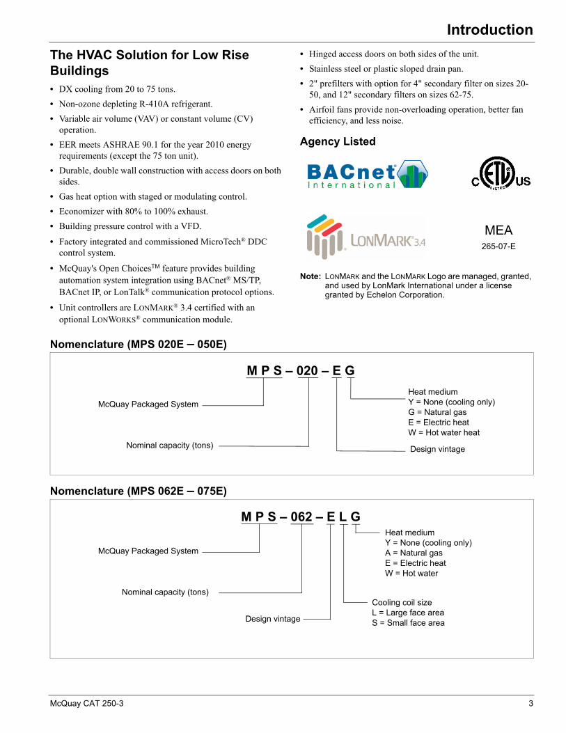
IntroductionThe HVAC Solution for Low Rise Buildings• DX cooling from 20 to 75 tons.
• Non-ozone depleting R-410A refrigerant.
• Variable air volume (VAV) or constant volume (CV) operation.
• EER meets ASHRAE 90.1 for the year 2010 energy requirements (except the 75 ton unit).
• Durable, double wall construction with access doors on both sides.
• Gas heat option with staged or modulating control.
• Economizer with 80% to 100% exhaust.
• Building pressure control with a VFD.
• Factory integrated and commissioned MicroTech® DDC control system.
• McQuay's Open ChoicesTM feature provides building automation system integration using BACnet® MS/TP, BACnet IP, or LonTalk® communication protocol options.
• Unit controllers are LONMARK® 3.4 certified with an optional LONWORKS® communication module.
• Hinged access doors on both sides of the unit.
• Stainless steel or plastic sloped drain pan.
• 2" prefilters with option for 4" secondary filter on sizes 20-50, and 12" secondary filters on sizes 62-75.
• Airfoil fans provide non-overloading operation, better fan efficiency, and less noise.
Agency Listed
Note: LONMARK and the LONMARK Logo are managed, granted, and used by LonMark International under a license granted by Echelon Corporation.
Nomenclature (MPS 020E – 050E)
Nomenclature (MPS 062E – 075E)
MEA265-07-E
M P S – 020 – E G
McQuay Packaged System
Heat mediumY = None (cooling only)G = Natural gasE = Electric heatW = Hot water heat
Design vintageNominal capacity (tons)
M P S – 062 – E L G
McQuay Packaged System
Heat mediumY = None (cooling only) A = Natural gasE = Electric heat W = Hot water
Design vintage
Nominal capacity (tons)Cooling coil sizeL = Large face area S = Small face area
McQuay CAT 250-3 3
Introduction
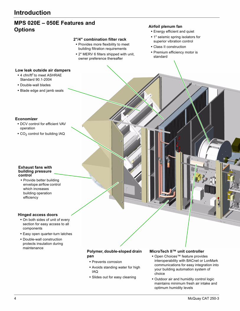
MPS 020E – 050E Features and Options
Hinged access doors• On both sides of unit of every
section for easy access to all components
• Easy open quarter-turn latches
• Double-wall construction protects insulation during maintenance
Polymer, double-sloped drain pan
• Prevents corrosion
• Avoids standing water for high IAQ
• Slides out for easy cleaning
Airfoil plenum fan• Energy efficient and quiet
• 1" seismic spring isolators for superior vibration control
• Class II construction
• Premium efficiency motor is standard
Low leak outside air dampers • 4 cfm/ft2 to meet ASHRAE
Standard 90.1-2004
• Double-wall blades
• Blade edge and jamb seals
Exhaust fans with building pressure control
• Provide better building envelope airflow control which increases building operation efficiency
2"/4" combination filter rack• Provides more flexibility to meet
building filtration requirements
• 2" MERV 6 filters shipped with unit, owner preference thereafter
Economizer • DCV control for efficient VAV
operation
• CO2 control for building IAQ
MicroTech II™ unit controller• Open Choices™ feature provides
interoperability with BACnet or LonMark communications for easy integration into your building automation system of choice
• Outdoor air and humidity control logic maintains minimum fresh air intake and optimum humidity levels
4 McQuay CAT 250-3

Introduction
MPS 020E – 050E Features and Options(continued)
R-410A refrigerant• No ozone depletion potential or
phase-out date
• Greater than 10.0 EER, meets ASHRAE 90.1-2007 energy requirements for the year 2010
• Dual refrigerant circuits provide redundancy for high unit reliability
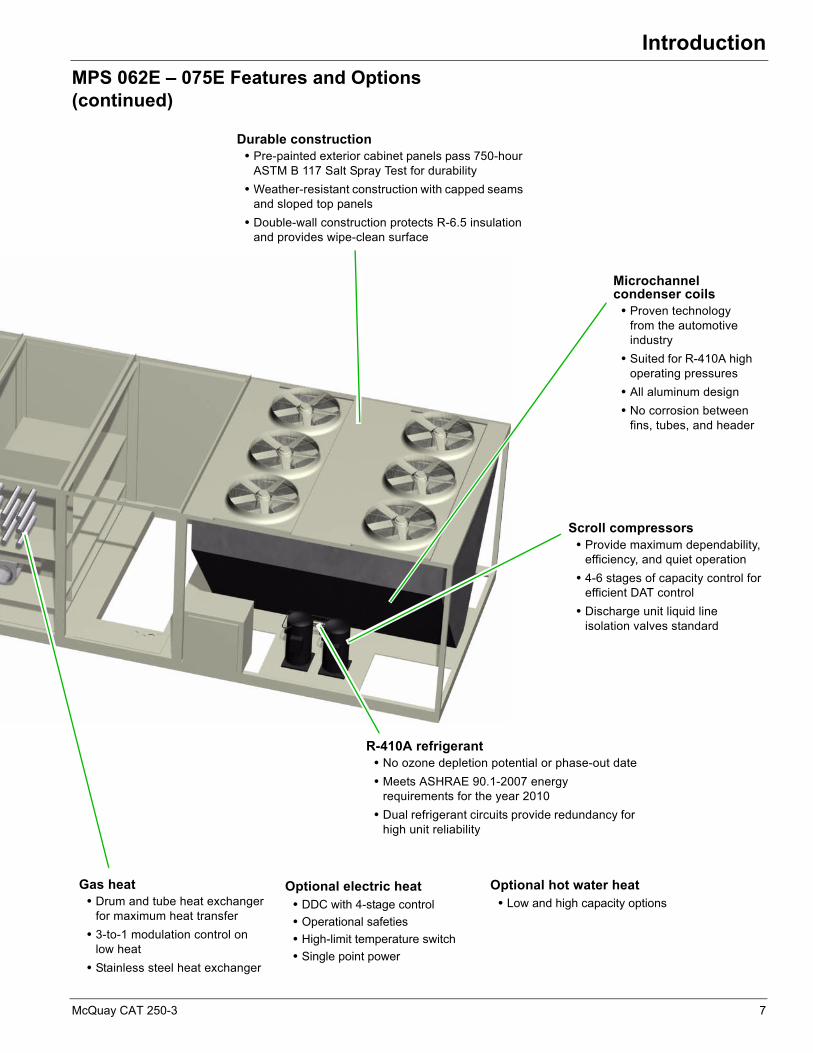
Scroll compressors• Provide maximum dependability,
efficiency, and quiet operation
• 4-5 stages of capacity control for efficient DAT control
Microchannel condenser coils
• Proven technology from the automotive industry
• Suited for R-410A high operating pressures
• All aluminum design
• No corrosion between fins, tubes, and header
Gas heat• Tubular heat exchanger for
maximum heat transfer
• Four-stage capacity control
• Optional 4-to-1 modulation control on low heat
• Optional 8-to-1 modulation control on high heat
Durable construction• Pre-painted exterior cabinet panels pass 750-hour
ASTM B 117 Salt Spray Test for durability
• Weather-resistant construction with capped seams and sloped top panels
• Double-wall construction protects R-4 insulation and provides wipe-clean surface
Optional electric heat• DDC with 4-stage control
• Operational safeties
• High-limit temperature switch
• Single point power
Optional hot water heat• Low and high capacity options
• DDC control ready with 0–10 volt wiring harness
• Vestibule for field installed control valve package
McQuay CAT 250-3 5
Introduction
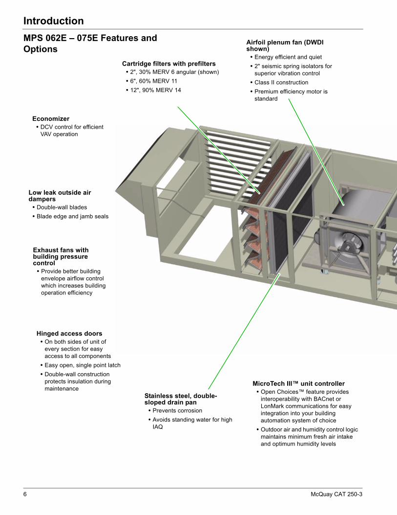
MPS 062E – 075E Features and Options
Hinged access doors• On both sides of unit of
every section for easy access to all components
• Easy open, single point latch
• Double-wall construction protects insulation during maintenance
Stainless steel, double-sloped drain pan
• Prevents corrosion
• Avoids standing water for high IAQ
Airfoil plenum fan (DWDI shown)
• Energy efficient and quiet
• 2" seismic spring isolators for superior vibration control
• Class II construction
• Premium efficiency motor is standard
Low leak outside air dampers
• Double-wall blades
• Blade edge and jamb seals
Exhaust fans with building pressure control
• Provide better building envelope airflow control which increases building operation efficiency
Cartridge filters with prefilters• 2", 30% MERV 6 angular (shown)
• 6", 60% MERV 11
• 12", 90% MERV 14
Economizer • DCV control for efficient
VAV operation
MicroTech III™ unit controller• Open Choices™ feature provides
interoperability with BACnet or LonMark communications for easy integration into your building automation system of choice
• Outdoor air and humidity control logic maintains minimum fresh air intake and optimum humidity levels
6 McQuay CAT 250-3
Introduction
MPS 062E – 075E Features and Options(continued)
R-410A refrigerant• No ozone depletion potential or phase-out date
• Meets ASHRAE 90.1-2007 energy requirements for the year 2010
• Dual refrigerant circuits provide redundancy for high unit reliability
Scroll compressors• Provide maximum dependability,
efficiency, and quiet operation
• 4-6 stages of capacity control for efficient DAT control
• Discharge unit liquid line isolation valves standard
Microchannel condenser coils
• Proven technology from the automotive industry
• Suited for R-410A high operating pressures
• All aluminum design
• No corrosion between fins, tubes, and header
Gas heat• Drum and tube heat exchanger
for maximum heat transfer
• 3-to-1 modulation control on low heat
• Stainless steel heat exchanger
Durable construction• Pre-painted exterior cabinet panels pass 750-hour
ASTM B 117 Salt Spray Test for durability
• Weather-resistant construction with capped seams and sloped top panels
• Double-wall construction protects R-6.5 insulation and provides wipe-clean surface
Optional electric heat• DDC with 4-stage control
• Operational safeties
• High-limit temperature switch
• Single point power
Optional hot water heat• Low and high capacity options
McQuay CAT 250-3 7
Features and Benefits
Features and BenefitsWhy Choose McQuay Rooftop Systems?
Maverick II rooftop systems are the HVAC solution for low rise building projects. Available with cooling capacities from 20 to 75 tons and energy efficiencies of 10.0 EER and higher. They offer the correct choice now to meet the ASHRAE 90.1 Energy Standard requirements for the year 2010. The use of a green refrigerant, R-410A, also meets the requirements of the United States EPA/Montreal Protocol to do away with ozone depleting refrigerants such as R-22.
Maverick II systems are built to perform, with features and options that provide for lower installed costs, high energy efficiency, good indoor air quality, quiet operation, low cost maintenance and service, and longevity. Completed systems are factory tested and shipped with a cETLus Safety Listing.
High Efficiencies and Competitively Priced
There’s no longer any reason to wait until 2010 to specify non-ozone-depleting R-410A refrigerant for your building projects. Because McQuay now offers a complete line of R-410A rooftop systems that exceed both current efficiency minimums and the new 2010 efficiency minimums.
Figure 1: 2010 Efficiency Minimums
Today’s Solution for 2010 Efficiency andEnvironmental Requirements
In January 2010, HVAC equipment can no longer be manufactured with R-22 refrigerant.
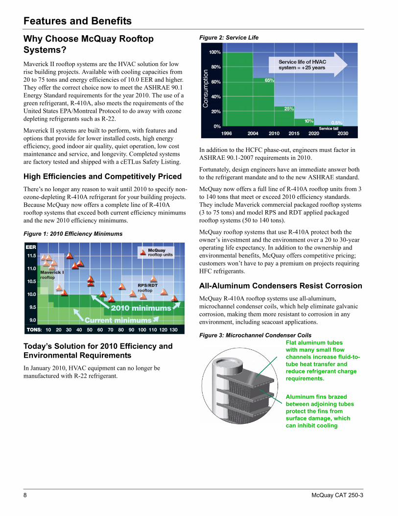
Figure 2: Service Life
In addition to the HCFC phase-out, engineers must factor in ASHRAE 90.1-2007 requirements in 2010.
Fortunately, design engineers have an immediate answer both to the refrigerant mandate and to the new ASHRAE standard.
McQuay now offers a full line of R-410A rooftop units from 3 to 140 tons that meet or exceed 2010 efficiency standards. They include Maverick commercial packaged rooftop systems (3 to 75 tons) and model RPS and RDT applied packaged rooftop systems (50 to 140 tons).
McQuay rooftop systems that use R-410A protect both the owner’s investment and the environment over a 20 to 30-year operating life expectancy. In addition to the ownership and environmental benefits, McQuay offers competitive pricing; customers won’t have to pay a premium on projects requiring HFC refrigerants.
All-Aluminum Condensers Resist Corrosion
McQuay R-410A rooftop systems use all-aluminum, microchannel condenser coils, which help eliminate galvanic corrosion, making them more resistant to corrosion in any environment, including seacoast applications.
Figure 3: Microchannel Condenser Coils
Maverick Irooftop
RPS/RDTrooftop
Flat aluminum tubes with many small flow channels increase fluid-to-tube heat transfer and reduce refrigerant charge requirements.
Aluminum fins brazed between adjoining tubes protect the fins from surface damage, which can inhibit cooling
8 McQuay CAT 250-3
Features and Benefits
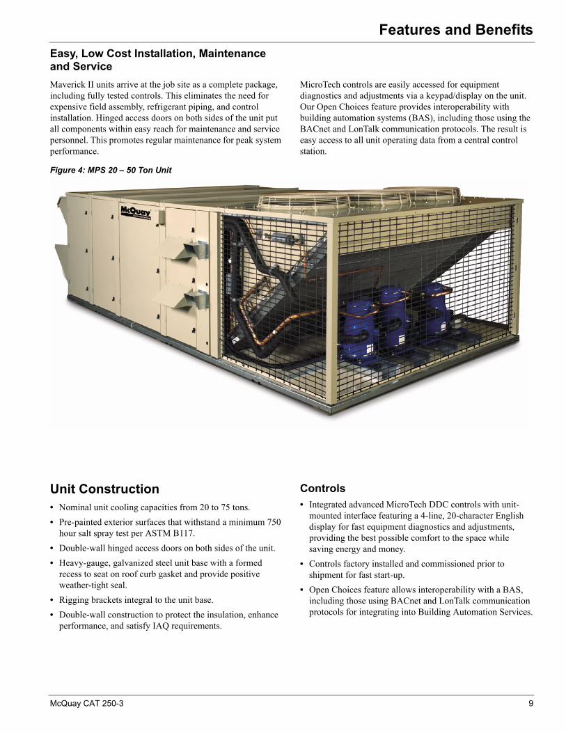
Easy, Low Cost Installation, Maintenanceand Service
Maverick II units arrive at the job site as a complete package, including fully tested controls. This eliminates the need for expensive field assembly, refrigerant piping, and control installation. Hinged access doors on both sides of the unit put all components within easy reach for maintenance and service personnel. This promotes regular maintenance for peak system performance.
MicroTech controls are easily accessed for equipment diagnostics and adjustments via a keypad/display on the unit. Our Open Choices feature provides interoperability with building automation systems (BAS), including those using the BACnet and LonTalk communication protocols. The result is easy access to all unit operating data from a central control station.
Figure 4: MPS 20 – 50 Ton Unit
Unit Construction• Nominal unit cooling capacities from 20 to 75 tons.
• Pre-painted exterior surfaces that withstand a minimum 750 hour salt spray test per ASTM B117.
• Double-wall hinged access doors on both sides of the unit.
• Heavy-gauge, galvanized steel unit base with a formed recess to seat on roof curb gasket and provide positive weather-tight seal.
• Rigging brackets integral to the unit base.
• Double-wall construction to protect the insulation, enhance performance, and satisfy IAQ requirements.
Controls• Integrated advanced MicroTech DDC controls with unit-
mounted interface featuring a 4-line, 20-character English display for fast equipment diagnostics and adjustments, providing the best possible comfort to the space while saving energy and money.
• Controls factory installed and commissioned prior to shipment for fast start-up.
• Open Choices feature allows interoperability with a BAS, including those using BACnet and LonTalk communication protocols for integrating into Building Automation Services.
McQuay CAT 250-3 9
Features and Benefits
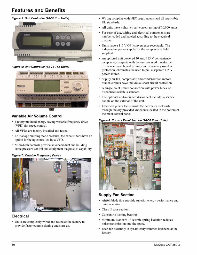
Figure 5: Unit Controller (20-50 Ton Units)
Figure 6: Unit Controller (62-75 Ton Units)
Variable Air Volume Control• Factory mounted energy saving variable frequency drive
(VFD) fan speed control.
• All VFDs are factory installed and tested.
• To manage building static pressure, the exhaust fans have an option for being controlled by a VFD.
• MicroTech controls provide advanced duct and building static pressure control and equipment diagnostics capability.
Figure 7: Variable Frequency Drives
Electrical• Units are completely wired and tested at the factory to
provide faster commissioning and start-up.
• Wiring complies with NEC requirements and all applicable UL standards.
• All units have a short circuit current rating of 10,000 amps.
• For ease of use, wiring and electrical components are number coded and labeled according to the electrical diagram.
• Units have a 115 V GFI convenience receptacle. The independent power supply for the receptacle is field supplied.
• An optional unit powered 20 amp 115 V convenience receptacle, complete with factory mounted transformer, disconnect switch, and primary and secondary overload protection, eliminates the need to pull a separate 115 V power source.
• Supply air fan, compressor, and condenser fan motors branch circuits have individual short circuit protection.
• A single point power connection with power block or disconnect switch is standard.
• The optional unit-mounted disconnect includes a service handle on the exterior of the unit.
• Electrical power feeds inside the perimeter roof curb through factory provided knockouts located in the bottom of the main control panel.
Figure 8: Control Panel Section (20-50 Tons Units)
Supply Fan Section• Airfoil blade fans provide superior energy performance and
quiet operation.
• Class II construction.
• Concentric locking bearing.
• Minimum, standard 1" seismic spring isolation reduces noise transmission into the space.
• Each fan assembly is dynamically trimmed balanced at the factory.
10 McQuay CAT 250-3
Features and Benefits
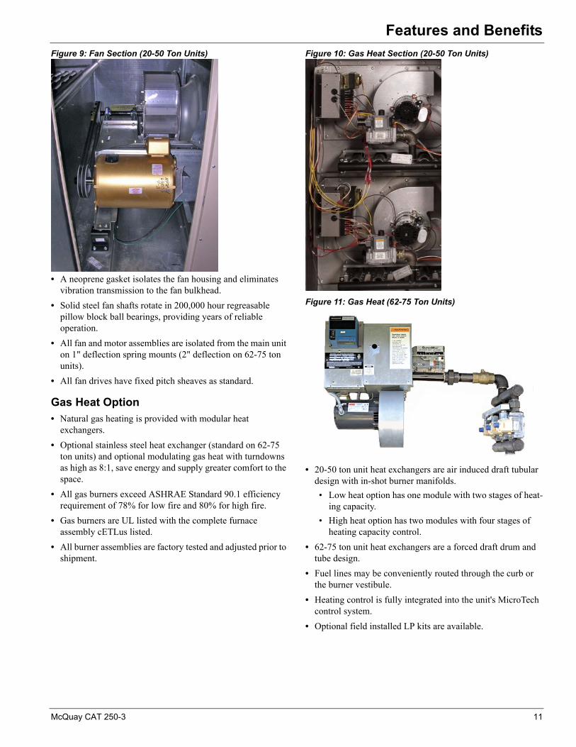
Figure 9: Fan Section (20-50 Ton Units)
• A neoprene gasket isolates the fan housing and eliminates vibration transmission to the fan bulkhead.
• Solid steel fan shafts rotate in 200,000 hour regreasable pillow block ball bearings, providing years of reliable operation.
• All fan and motor assemblies are isolated from the main unit on 1" deflection spring mounts (2" deflection on 62-75 ton units).
• All fan drives have fixed pitch sheaves as standard.
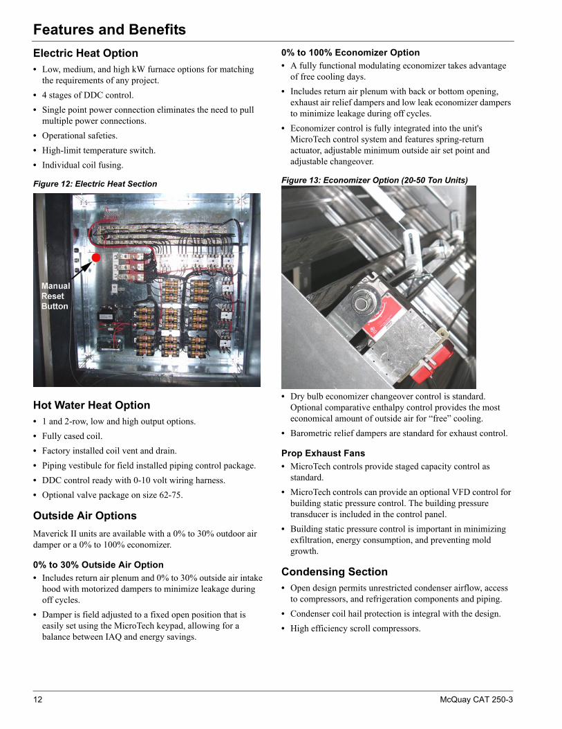
Gas Heat Option• Natural gas heating is provided with modular heat
exchangers.
• Optional stainless steel heat exchanger (standard on 62-75 ton units) and optional modulating gas heat with turndowns as high as 8:1, save energy and supply greater comfort to the space.
• All gas burners exceed ASHRAE Standard 90.1 efficiency requirement of 78% for low fire and 80% for high fire.
• Gas burners are UL listed with the complete furnace assembly cETLus listed.
• All burner assemblies are factory tested and adjusted prior to shipment.
Figure 10: Gas Heat Section (20-50 Ton Units)
Figure 11: Gas Heat (62-75 Ton Units)
• 20-50 ton unit heat exchangers are air induced draft tubular design with in-shot burner manifolds.
• Low heat option has one module with two stages of heat-ing capacity.
• High heat option has two modules with four stages of heating capacity control.
• 62-75 ton unit heat exchangers are a forced draft drum and tube design.
• Fuel lines may be conveniently routed through the curb or the burner vestibule.
• Heating control is fully integrated into the unit's MicroTech control system.
• Optional field installed LP kits are available.
McQuay CAT 250-3 11
Features and Benefits
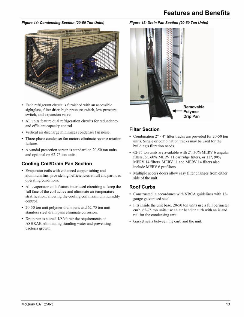
Electric Heat Option• Low, medium, and high kW furnace options for matching
the requirements of any project.
• 4 stages of DDC control.
• Single point power connection eliminates the need to pull multiple power connections.
• Operational safeties.
• High-limit temperature switch.
• Individual coil fusing.
Figure 12: Electric Heat Section
Hot Water Heat Option• 1 and 2-row, low and high output options.
• Fully cased coil.
• Factory installed coil vent and drain.
• Piping vestibule for field installed piping control package.
• DDC control ready with 0-10 volt wiring harness.
• Optional valve package on size 62-75.
Outside Air Options
Maverick II units are available with a 0% to 30% outdoor air damper or a 0% to 100% economizer.
0% to 30% Outside Air Option
• Includes return air plenum and 0% to 30% outside air intake hood with motorized dampers to minimize leakage during off cycles.
• Damper is field adjusted to a fixed open position that is easily set using the MicroTech keypad, allowing for a balance between IAQ and energy savings.
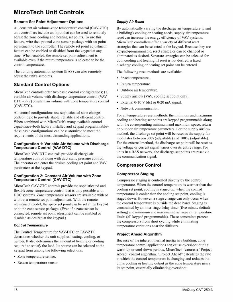
0% to 100% Economizer Option
• A fully functional modulating economizer takes advantage of free cooling days.
• Includes return air plenum with back or bottom opening, exhaust air relief dampers and low leak economizer dampers to minimize leakage during off cycles.
• Economizer control is fully integrated into the unit's MicroTech control system and features spring-return actuator, adjustable minimum outside air set point and adjustable changeover.
Figure 13: Economizer Option (20-50 Ton Units)
• Dry bulb economizer changeover control is standard. Optional comparative enthalpy control provides the most economical amount of outside air for “free” cooling.
• Barometric relief dampers are standard for exhaust control.
Prop Exhaust Fans
• MicroTech controls provide staged capacity control as standard.
• MicroTech controls can provide an optional VFD control for building static pressure control. The building pressure transducer is included in the control panel.
• Building static pressure control is important in minimizing exfiltration, energy consumption, and preventing mold growth.
Condensing Section• Open design permits unrestricted condenser airflow, access
to compressors, and refrigeration components and piping.
• Condenser coil hail protection is integral with the design.
• High efficiency scroll compressors.
12 McQuay CAT 250-3
Features and Benefits
Figure 14: Condensing Section (20-50 Ton Units)
• Each refrigerant circuit is furnished with an accessible sightglass, filter drier, high pressure switch, low pressure switch, and expansion valve.
• All units feature dual refrigeration circuits for redundancy and efficient capacity control.
• Vertical air discharge minimizes condenser fan noise.
• Three-phase condenser fan motors eliminate reverse rotation failures.
• A vandal protection screen is standard on 20-50 ton units and optional on 62-75 ton units.
Cooling Coil/Drain Pan Section• Evaporator coils with enhanced copper tubing and
aluminum fins, provide high efficiencies at full and part load operating conditions.
• All evaporator coils feature interlaced circuiting to keep the full face of the coil active and eliminate air temperature stratification, allowing the cooling coil maximum humidity control.
• 20-50 ton unit polymer drain pans and 62-75 ton unit stainless steel drain pans eliminate corrosion.
• Drain pan is sloped 1/8"/ft per the requirements of ASHRAE, eliminating standing water and preventing bacteria growth.
Figure 15: Drain Pan Section (20-50 Ton Units)
Filter Section• Combination 2" - 4" filter tracks are provided for 20-50 ton
units. Single or combination tracks may be used for the building's filtration needs.
• 62-75 ton units are available with 2", 30% MERV 6 angular filters, 6", 60% MERV 11 cartridge filters, or 12", 90% MERV 14 filters. MERV 11 and MERV 14 filters also include MERV 6 prefilters.
• Multiple access doors allow easy filter changes from either side of the unit.
Roof Curbs• Constructed in accordance with NRCA guidelines with 12-
gauge galvanized steel.
• Fits inside the unit base. 20-50 ton units use a full perimeter curb. 62-75 ton units use an air handler curb with an island rail for the condensing unit.
• Gasket seals between the curb and the unit.
McQuay CAT 250-3 13

MicroTech Unit Controls
MicroTech Unit ControlsSuperior Performance and Easy Integration
Each Maverick II rooftop unit is equipped with a complete MicroTech unit control system that is pre-engineered and factory tested prior to shipment. Its features include:
• Stable, efficient temperature and static pressure control.
• Comprehensive diagnostics.
• Alarm monitoring.
• Alarm-specific component shutdown if critical equipment conditions occur.
The MicroTech control system comes standard with a user interface, providing system operators with superior access to temperatures, pressures, operating states, alarm messages, control parameters, and schedules. All messages display in English text. Password protection is included to protect against unauthorized or accidental set point or parameter changes.
MicroTech control system components include:
• DDC controller with keypad/display user interface.
• Ductwork or building pressure transducers.
• Unit-mounted temperature sensors.
• Field installed zone temperature sensor packages.
• Enthalpy sensors/controllers.
• Field installed CO2 sensors.
Open Choices™ Feature
MicroTech unit control systems are factory configured for either stand-alone operation or for incorporation into an independent building automation systems (BAS) through McQuay’s Open Choices feature. This feature provides building automation system integration using BACnet MS/TP, BACnet IP, or LonTalk communication protocol options.
BACnet communications conform to the BACnet Standard, ANSI/ASHRAE Standard 135-2004, and are supported by a protocol implementation conformance statement (PICS).
LonTalk communications are in accordance with either the Discharge Air Controller (DAC) or Space Comfort Controller (SCC) profiles and are LONMARK 3.4 certified.
The building automation system can interact with one or more rooftop unit controllers in any of the following ways:
• Sets the unit’s operating and occupancy modes.
• Monitors all controller inputs, outputs, set points, parameters, and alarms.
• Sets controller set points and parameters.
• Clears alarms.
• Resets the cooling discharge air temperature set points (VAV units).
• Resets the duct static pressure set point (VAV units).
• Sets the heat/cool changeover temperature.
• Sets the representative zone temperature (CAV-ZTC units).
DDC Unit Controller
The DDC controller contains a microprocessor that is preprogrammed with the software necessary to control the unit. This can keep schedules, set points and parameters from being lost, even during a 48-hour power outage. The microprocessor board processes system input data and then determines and controls output responses.
Communication Modules
Field installed communication modules provide the means to configure MicroTech unit controls for interoperability with an independent BAS using McQuay's innovative Open Choices feature. Communication modules are available to support BACnet MS/TP, BACnet/IP, and LONMARK communication protocols.
Keypad/Display
The keypad/display provides a user interface with the main controller and has easy-to-use keys and control knob used for navigation and entering changes. The display is a 4-line by 20-character format with clear English display messages. All operating conditions, system alarms, control parameters and schedules can be monitored from the keypad/display. If the correct password has been entered, any adjustable parameter or schedule can be modified from the keypad.
Figure 16: Keypad/Display Interface
Unit Sensors
Temperature and Enthalpy Sensors
• The return, discharge, and outside air temperature sensors are factory installed. The zone temperature sensor package can be ordered as a field installed option.
14 McQuay CAT 250-3

MicroTech Unit Controls
Zone Temperature Sensors
Two optional zone temperature sensors are available:
1 Zone sensor with tenant override.
2 Zone sensor with tenant override and remote set point adjustment.
Timed tenant override is a standard MicroTech control feature.
Zone sensors are required for the controller's space reset of supply air set point and night setback features. All zone sensors are field installed with field wiring terminated at the unit controller.
The optional comparative enthalpy control economizer package is provided with the enthalpy sensor for the return air and outside air factory installed.
Static Pressure Transducers
When the McQuay Packaged System is ordered with the VAV option, the duct static pressure transducer is factory installed as standard. The units can also have an exhaust fan option. The exhaust fans on VAV units are controlled by the building static pressure control package. The exhaust fans on CAV units are controlled by either the building static pressure control package as mentioned above, or they are controlled by the DDC program based on the outside air damper position. The static pressure transducers are factory installed when building static pressure control is ordered. The installation and routing of the field-supplied sampling tubes is done at the time of the unit installation.
Stand-Alone Controller Features
MicroTech rooftop unit controls include all of the essential features required to make them capable of independent and stand-alone operation.
Auto/Manual Operation Selection
Automatic or manual operation can be controlled at the keypad. The keypad provides a variety of occupancy and auto/manual control mode selections available to the operator:
Cooling and Heating Lockout Control
All unit controls include separate keypad-programmable set points for locking out mechanical cooling and heating. Mechanical cooling is locked out when the outdoor temperature is below the cooling lockout set point. Heating is locked out when the outdoor temperature is above the heating
lockout set point. This feature can save energy cost by eliminating unnecessary heating and cooling during periods when the outdoor air temperature is mild.
Night/Unoccupied Setback
When one of the zone temperature sensors is connected to the unit controller, night setback heating control and night setback cooling control are available. Separate, keypad-programmable, night heating and night cooling set points are used to start the unit when necessary. After the unit starts, night setback control is similar to normal occupied control except that the minimum outside air damper position is set to zero. If the outside air is suitable for free cooling, it is used during night setback operation.
Internal Time Clock
An internal time clock is included in the MicroTech unit controller. Current date and time can be quickly and easily set at the user interface keypad.
Internal Schedule
Seven daily schedules and holiday schedules can be entered at the keypad of all unit controllers. For each of these eight schedules, one start and one stop time can be entered. Up to 16 holiday periods of any duration can be designated. The unit will automatically run according to the holiday schedule on the holiday dates.
In lieu of its internal schedule, the unit can be operated according to a network schedule from a BAS.
External Time Clock or Tenant Override Input
An input is supplied that can be used to accept a field wired start/stop signal from a remote source. An external time clock, a tenant override switch, or both may be connected. Whenever the external circuit is closed, the controller overrides the internal schedule (if activated) and places the unit into the occupied mode.
If the internal schedule or a BAS network schedule is used, field wiring is not required.
Timed Tenant Override
Off-hour operation flexibility is a must in today's office environments and the stand-alone MicroTech II controls handle it with ease. When unit operation is desired during unoccupied hours the tenant override button on either of the optional zone sensor packages is pressed to initiate the override operation. The unit then starts and runs in the occupied mode for a keypad-adjustable length of time (up to five hours). If the button is pressed again while the unit is operating, the timer resets to the full time allowance without interrupting unit operation. Tenant override operation can also be initiated by a BAS.
Occupancy Modes Control Modes
Auto Off Manual
Occupied Auto or Heat/Cool
Unoccupied Cool Only
Bypass (tenant override)Heat Only
Fan Only
McQuay CAT 250-3 15
MicroTech Unit Controls
Remote Set Point Adjustment Options
All constant air volume-zone temperature control (CAV-ZTC) unit controllers include an input that can be used to remotely adjust the zone cooling and heating set points. To use this feature, wire the optional zone sensor package with set point adjustment to the controller. The remote set point adjustment feature can be enabled or disabled from the keypad at any time. When enabled, the remote set point adjustment is available even if the return temperature is selected to be the control temperature.
The building automation system (BAS) can also remotely adjust the unit's setpoints.
Standard Control Options
MicroTech controls offer two basic control configurations; (1) variable air volume with discharge temperature control (VAV-DTC) or (2) constant air volume with zone temperature control (CAV-ZTC).
All control configurations use sophisticated state change control logic to provide stable, reliable and efficient control. When combined with MicroTech's many available control capabilities–both factory installed and keypad programmable–these basic configurations can be customized to meet the requirements of the most demanding applications.
Configuration 1: Variable Air Volume with Discharge Temperature Control (VAV-DTC)
MicroTech VAV-DTC controls provide discharge air temperature control along with duct static pressure control. The operator can enter the desired cooling set point and VAV parameters at the keypad.
Configuration 2: Constant Air Volume with Zone Temperature Control (CAV-ZTC)
MicroTech CAV-ZTC controls provide the sophisticated and flexible zone temperature control that is only possible with DDC systems. Zone temperature sensors are available with or without a remote set point adjustment. With the remote adjustment model, the space set point can be set at the keypad or at the zone sensor package. (Even if a zone sensor is connected, remote set point adjustment can be enabled or disabled as desired at the keypad.)
Control Temperature
The Control Temperature for VAV-DTC or CAV-ZTC determines whether the unit supplies heating, cooling, or neither. It also determines the amount of heating or cooling required to satisfy the load. Its source can be selected at the keypad from among the following selections:
• Zone temperature sensor.
• Return temperature sensor.
Supply Air Reset
By automatically varying the discharge air temperature to suit a building's cooling or heating needs, supply air temperature reset can increase the energy efficiency of VAV systems. MicroTech controllers offer a variety of different reset strategies that can be selected at the keypad. Because they are keypad-programmable, reset strategies can be changed or eliminated as desired. Separate strategies can be selected for both cooling and heating. If reset is not desired, a fixed discharge cooling or heating set point can be entered.
The following reset methods are available:
• Space temperature.
• Return temperature.
• Outdoor air temperature.
• Supply airflow (VAV, cooling set point only).
• External 0-10 V (dc) or 0-20 mA signal.
• Network communication.
For all temperature reset methods, the minimum and maximum cooling and heating set points are keypad programmable along with the corresponding minimum and maximum space, return or outdoor air temperature parameters. For the supply airflow method, the discharge set point will be reset as the supply fan modulates between 30% (adjustable) and 100% (adjustable). For the external method, the discharge set point will be reset as the voltage or current signal varies over its entire range. For units in a BAS network, the discharge set points are reset via the communication signal.
Compressor Control
Compressor Staging
Compressor staging is controlled directly by the control temperature. When the control temperature is warmer than the cooling set point, cooling is staged up; when the control temperature is cooler than the cooling set point, cooling is staged down. However, a stage change can only occur when the control temperature is outside the dead band. Staging is constrained by an inter-stage delay timer (five minute default setting) and minimum and maximum discharge air temperature limits (all keypad programmable). These constraints protect the compressors from short cycling while eliminating temperature variations near the diffusers.
Project Ahead Algorithm
Because of the inherent thermal inertia in a building, zone temperature control applications can cause overshoot during warm-up or cool-down periods, MicroTech features a “Project Ahead” control algorithm. “Project Ahead” calculates the rate at which the control temperature is changing and reduces the unit's cooling or heating output as the zone temperature nears its set point, essentially eliminating overshoot.
16 McQuay CAT 250-3
MicroTech Unit Controls
Supply Fan Control
Duct Static Pressure Control
On all VAV-DTC units, duct static pressure control is maintained by a control algorithm which provides precise control of the supply fan variable frequency drive. The keypad programmable set point can be set between 0.20" wc and 2.00" wc.
Economizer Control
Economizer Changeover Selection
On units equipped with an economizer, there are two methods of determining whether the outdoor air is suitable for free cooling.
• The standard offering uses an internal dry bulb changeover strategy: the unit controller compares the outdoor air dry-bulb temperature to a keypad-programmable set point.
• The optional second method is a comparative enthalpy control. It uses a solid state device that compares the outdoor air ambient enthalpy to the return air enthalpy. When the outdoor air enthalpy is lower than the return air enthalpy, the unit will change to economizer operation.
Minimum Ventilation Air Volume Control
Consistently maintaining the minimum outdoor air requirements of ASHRAE Standard 62 has been a long-standing control challenge for VAV systems. As supply air fan volumes were reduced, the volume of air introduced through a fixed-position, minimum outdoor air damper was also reduced, compromising indoor air quality. To meet this challenge, MicroTech controls feature user-selected control methods for maintaining outdoor air volume.
MicroTech controls have a keypad-selected control function that automatically adjusts outdoor air damper position in response to changes in supply air fan volume. Regardless of supply air volume, this strategy maintains a nearly constant outdoor air volume at all times.
The outdoor air damper position can also be controlled by the following:
• The MicroTech controller can accept an external 0-10 V (dc) or a 0-20 mA signal from a control device or from a CO2
sensor.
• The MicroTech controller can accept a BAS network signal for the minimum position.
• A fixed minimum damper position can be keypad programmed. This selection may be acceptable when ventilation requirements are met through other sources.
During cold ambient conditions where the mixed air temperature of the minimum outdoor air and the return air can become too low, MicroTech controls maintain the minimum discharge temperature set point by controlling the unit's heating system.
Exhaust Fan Control
Building Static Pressure Control
Any constant or variable air volume Maverick unit with an optional variable volume exhaust fan can be provided with direct building static pressure control capability. The building static pressure is measured and processed by the unit DDC controller. The controller provides precise control of the exhaust fan's variable speed drive to maintain the space pressure set point. The range of the keypad-programmable set point is between –0.25 and +0.25" wc.
Field Output Signals
All MicroTech controls include two solid-state relay outputs that are available for field connection to any suitable device: a remote alarm output and a fan operation output. These outputs are used to signal field equipment of unit status.
Remote Alarm Output
The remote alarm output can be used to operate a 24 V relay to provide a remote alarm signal to a light, audible alarm, or other device when an alarm condition exists at the unit.
Fan Operation Output
The fan operation output is used to operate a 24 V relay to control field equipment that depends on fan operation, such as field-installed isolation dampers or VAV boxes. To allow actuators enough time to stroke, the fan operation output is energized three minutes before the fan starts. It then remains energized until thirty seconds after the unit airflow switch senses no airflow. The fan operation output is on whenever the unit airflow switch senses airflow.
McQuay CAT 250-3 17

MicroTech Unit Controls
Alarm Management and Control
MicroTech unit controllers are capable of sophisticated alarm management and controlled response functions. Each alarm is prioritized, indicated, and responded to with the appropriate action. The current alarm (up to four alarms, arranged by alarm priority), each with a time and date stamp, can be displayed at the user interface.
Alarm Priority
The various alarms that can occur are prioritized according to the severity of the problem. Three alarm categories are used: (1) Faults, (2) Problems, and (3) Warnings.
1 Faults are the highest priority alarms. If a fault condition occurs, the complete unit is shut down until the alarm condition is gone and the fault is manually cleared at the keypad. A fault example is a “Fan Fail” alarm.
2 Problems are the next lower priority to faults. If a problem occurs, the complete unit does not shut down, but its operation is modified to compensate for the alarm condition. A problem automatically clears when the alarm condition that caused it is gone. “Lo Pres-Ckt1” is an example of a problem where only the affected compressor is shut down.
3 Warnings are the lowest priority alarms. No control action is taken when a warning occurs; it is simply indicated to alert the operator that the alarm condition needs attention. To remind the operator to read warnings, they must be manually cleared. “Dirty Filter” indication is an example of a warning.
Table 1: MicroTech Alarm Summary
Alarm name Fault Problem Warning
Emergency Off XControl T Fail XDisch Sensor XDuct Hi Limit X
Hi Return Tmp XHi Disch Tmp XLo Disch Tmp X
Fan Fail XOAT Sensor X
Space Sensor XReturn Sensor XHi Pres-Ckt1 XHi Pres-Ckt2 XLo Pres-Ckt1 XLo Pres-Ckt2 X
Dirty Filter X
18 McQuay CAT 250-3
Application Considerations
Application ConsiderationsGeneral Rooftop Applications
Units are intended for use in normal heating, ventilating, and air conditioning applications. Consult your local McQuay sales representative for applications involving operation at high ambient temperatures, high altitudes, non-cataloged voltages, and for job specific unit selections that fall outside of the range of the catalog tables.
For proper operation, units should be rigged in accordance with instructions stated in IM 842. Fire dampers, if required, must be installed in the ductwork according to local or state codes. No space is allowed for these dampers in the unit. Follow factory check, test and start procedures explicitly to achieve satisfactory start-up and operation (see IM 842).
Most rooftop applications take advantage of the significant energy savings provided with economizer operation. When an economizer system is used, mechanical refrigeration is typically not required below an ambient temperature of 50°F. Standard MPS refrigeration systems are designed to operate in ambient temperatures down to 20°F for 20-50 ton units or 45°F for 62-75 ton units.
Unit Location
The structural engineer must verify that the roof has adequate strength and ability to minimize deflection. Take extreme caution when using a wooden roof structure.
Unit condenser coils should be located to avoid contact with any heated exhaust air.
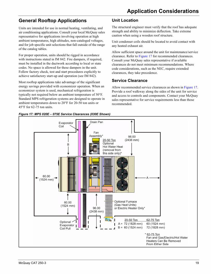
Allow sufficient space around the unit for maintenance/service clearance. Refer to Figure 17 for recommended clearances. Consult your McQuay sales representative if available clearances do not meet minimum recommendations. Where code considerations, such as the NEC, require extended clearances, they take precedence.
Service Clearance
Allow recommended service clearances as shown in Figure 17. Provide a roof walkway along the sides of the unit for service and access to controls and components. Contact your McQuay sales representative for service requirements less than those recommended.
Figure 17: MPS 020E – 075E Service Clearances (030E Shown)
McQuay CAT 250-3 19
Application Considerations
Curb Installation
The roof curb is field assembled and must be installed level (within 1/16" per foot side to side). A sub-base has to be constructed by the contractor in applications involving pitched roofs. Gaskets are furnished and must be installed between the unit and curb. For proper installation, follow NRCA guidelines. Typical curb installation is illustrated in Figure 41, page 52 and Figure 45, page 56. In applications requiring post and rail installation, an I-beam securely mounted on multiple posts should support the unit on each side. In addition the insulation on the underside of the unit should also be protected from the elements.
Applications in geographic areas subjected to seismic or hurricane conditions must meet code requirements for fastening the unit to the curb and the curb to the building structure.
Acoustical Considerations
Good acoustical design is critical for any installation and should start at the earliest stages in the design process. Common sound paths for rooftop equipment must be addressed are:
• Radiated sound through the bottom of the unit (air handling section and condensing section) and into the space.
• Radiated sound to the property line.
• Structure-borne vibration from the unit to the building.
• Airborne sound through the supply air duct.
• Airborne sound through the return air duct.
Locating rooftop equipment away from sound sensitive areas is critical and the most cost effective means of avoiding sound problems. If possible, rooftop equipment should always be located over less sensitive areas such as corridors, toilet facilities or auxiliary spaces and away from office areas, conference rooms and classrooms.
Some basic guidelines for good acoustical performance are:
• Provide proper structural support under all areas of the unit.
• Always locate the unit's center of gravity close to a main support to minimize roof deflection.
• Use a concrete deck or pad when a unit has to be located over an occupied space where good acoustics are essential.
• Only the supply and return air ducts should penetrate the acoustical material and decking within the curb perimeter, and the openings must be sealed once the duct is installed.
• Don't overlook the return air path. Never leave a clear “line of sight” into a return or exhaust fan; always include some duct work (acoustically lined tee) at the return inlet.
• Place an acoustical material in the area directly beneath the condensing section.
• Select acoustical material that discourages microbial growth.
• Minimize system static pressure losses to reduce fan sound generation.
• Design duct systems to minimize turbulence.
• Account for low frequency duct breakout in system design. Route the first 20 ft. of rectangular duct over non-sensitive areas and avoid large duct aspect ratios. Consider round or oval duct to reduce breakout.
There are many sound sources in rooftop systems. Fans, compressors, condenser fans, duct take-offs, etc., all generate sound. For guidelines on reducing sound generation in the duct system, refer to the ASHRAE Applications Handbook.
Contact your local McQuay sales representative for equipment supply, return and radiated sound power data specific to your application.
Ductwork Considerations
A well-designed duct system is required to allow the rooftop equipment to provide rated performance and to minimize system resistance and sound generation. Duct connections to and from units should allow straight, smooth airflow transitions. Avoid any abrupt change in duct size and sharp turns in the fan discharge. Avoid turns opposed to wheel rotation since they generate air turbulence and result in unwanted sound. If 90° turns are necessary, use turning vanes. Refer to the ASHRAE Applications Handbook for specific guidelines relevant to rooftop equipment.
Return Duct
The return path is the most often overlooked. A section of return duct is required to avoid a “line of sight” to the return air opening and to provide attenuation of return air sound. Install an insulated tee with a maximum duct velocity of 1000 to 1200 feet per minute. Extend the duct 15 feet to provide adequate attenuation.
Supply Duct
Insulate supply air ductwork for at least the first 20 feet from the unit. Consider the use of round or oval ductwork, as it significantly reduces low frequency breakout noise near the equipment. If rectangular duct is used, keep the aspect ratio of the duct as low as possible. The large flat surfaces associated with high aspect ratios increase low frequency breakout to the space and can generate noise, such as “oil canning.” The maximum recommended supply duct velocity is 1800 to 2000 feet per minute.
Duct High Limit
A McQuay Packaged System with VAV control includes a duct high limit switch as a standard feature that is of particular importance when fast acting, normally closed boxes are used.
Vibration Isolation
Make duct attachments to the unit with a flexible connection.
20 McQuay CAT 250-3
Application Considerations
Economizer and Exhaust Fan Application
Rooftop economizer applications usually require exhaust fans to properly control building pressure and maintain minimum ventilation.
The air balancer must adjust the outdoor air damper to provide minimum ventilation settings.
The EAF is normally off during non-economizer operation. During these minimum outdoor air conditions, the system essentially acts like a supply fan only system.
Smoke and Fire Protection
Due to the wide variation in building design and ambient operating conditions into which our units are applied, we do not represent or warrant that our products are fit and sufficient for smoke, fume, and fire control purposes. The owner and a fully qualified building designer are responsible for meeting all local and NFPA building code requirements with respect to smoke, fume, and fire control.
The unit's control panel has a terminal block that a supply air and return air smoke detector can be wired to. An optional return air smoke detector is offered. Any other smoke detector, its installation, and the wiring to the unit controller are all field supplied.
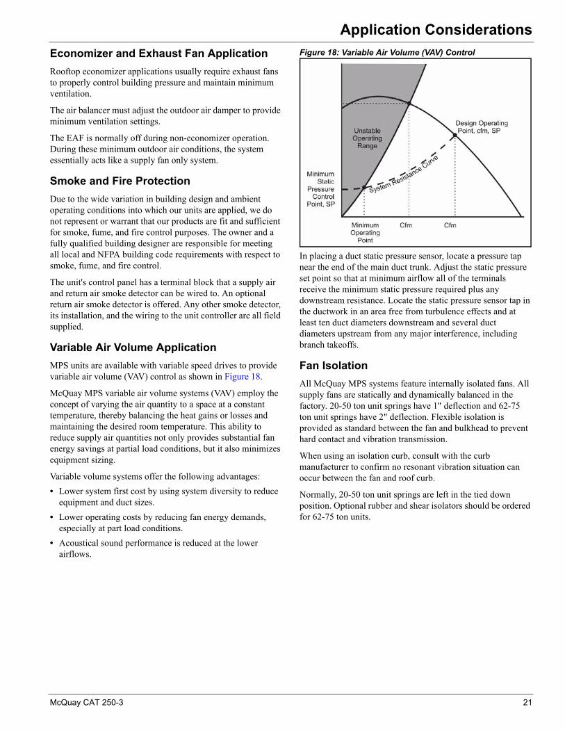
Variable Air Volume Application
MPS units are available with variable speed drives to provide variable air volume (VAV) control as shown in Figure 18.
McQuay MPS variable air volume systems (VAV) employ the concept of varying the air quantity to a space at a constant temperature, thereby balancing the heat gains or losses and maintaining the desired room temperature. This ability to reduce supply air quantities not only provides substantial fan energy savings at partial load conditions, but it also minimizes equipment sizing.
Variable volume systems offer the following advantages:
• Lower system first cost by using system diversity to reduce equipment and duct sizes.
• Lower operating costs by reducing fan energy demands, especially at part load conditions.
• Acoustical sound performance is reduced at the lower airflows.
Figure 18: Variable Air Volume (VAV) Control
In placing a duct static pressure sensor, locate a pressure tap near the end of the main duct trunk. Adjust the static pressure set point so that at minimum airflow all of the terminals receive the minimum static pressure required plus any downstream resistance. Locate the static pressure sensor tap in the ductwork in an area free from turbulence effects and at least ten duct diameters downstream and several duct diameters upstream from any major interference, including branch takeoffs.
Fan Isolation
All McQuay MPS systems feature internally isolated fans. All supply fans are statically and dynamically balanced in the factory. 20-50 ton unit springs have 1" deflection and 62-75 ton unit springs have 2" deflection. Flexible isolation is provided as standard between the fan and bulkhead to prevent hard contact and vibration transmission.
When using an isolation curb, consult with the curb manufacturer to confirm no resonant vibration situation can occur between the fan and roof curb.
Normally, 20-50 ton unit springs are left in the tied down position. Optional rubber and shear isolators should be ordered for 62-75 ton units.
McQuay CAT 250-3 21

Application Considerations
Fan Operating Range
The acceptable system operating range of the McQuay rooftop is determined by all of the following characteristics. Each of these limiting factors must be considered for proper performance and component design life:
• Unstable fan operation.
• Maximum fan rpm.
• Maximum cabinet static pressure.
• Maximum face velocity (cooling coil is most important).
• Minimum furnace velocity.
• Turndown capability on VAV applications.
• Compressor operating pressures.
Indoor Fan and Motor Heat
The indoor fan and motor electrical consumption is a sensible cooling load approximately equal to 2.8 MBh per bhp (depending slightly on motor efficiency). The fan and motor temperature rise is equal to Btuh/(1.08 × cfm) and is typically about 3°F.
Altitude Adjustments
Fan Curve Performance
Fan curve performance is based on 70°F air temperature and sea level elevation. Selections at any other conditions require adjustment for air densities listed in Table 2. Higher elevations generally require more rpm to provide a given static pressure but less bhp due to the decrease in air density.
Example:
Assume 12,000 cfm is required at 2.0" TSP. The elevation is 5000 ft. and 70°F average air temperature is selected. A 24" SWSI airfoil fan is selected.
1 The density adjustment factor for 5000 ft. and 70°F is 0.83.
2 TSP must be adjusted as follows: 2.0" / 0.83 = 2.4".
3 Locate 12,000 cfm and 2.4 on the fan curve. Rpm = 1700 and bhp = 9.
4 Consumed fan power at design = 9 bph × 0.83 = 7.5 bhp.
Condenser Performance
Altitudes greater than sea level require a derate in condenser and cooling performance that can be estimated as follows:
For altitudes up to 6000 feet:
• Cooling capacity decrease factor (all sizes) = 0.5% per 1000 feet.
• Compressor kW increase factor = 0.6% per 1000 feet.
For altitudes above 6000 feet, consult the factory. The actual derate varies with each individual unit and design conditions. Your local McQuay representative can provide exact performance data.
Furnace Performance
Gas heat performance data is based on standard 70°F air temperature and zero feet altitude (sea level).
For altitudes between 2000 to 6000 feet, the gas burner must be derated 4% for every 1000 feet of altitude.
Example:
A 400 MBh furnace at an altitude of 3000 feet is derated (0.04 × 3 = 0.12). At 400 MBh input (400 × 0.12 MBh), the actual input is (400 - 48 = 352 MBh) at 3000 feet.
For altitudes above 6000 feet, consult the factory.
System Operating Limits
McQuay MPS systems are designed to operate over an extensive operating range. However, for proper system operation some limits do apply.
To help prevent moisture blow-off, design guidelines have been established for cooling coil selection. Based on laboratory testing, average coil face velocities should not exceed 600 ft./min. For applications outside of these limits, consult your McQuay sales representative.
In addition to maximum face velocity limitations, minimum velocity guidelines must also be followed. In order to maintain proper refrigeration performance, the minimum coil face velocity is 175 ft./min. When selecting a variable air volume unit, it is necessary to design the system such that the 175 ft./min. limit is maintained at light load conditions.
Condensate Drainage
Provide all drain pans with a properly sized p-trap to allow free drainage of coil condensate. For trap sizing, follow
Table 2: Temperature and Altitude Conversion Factors
Air temp (°F)
Altitude (feet)
0 1000 2000 3000 4000 5000 6000 7000 8000
-20 1.20 1.16 1.12 1.08 1.04 1.00 0.97 0.93 0.89
0 1.15 1.10 1.08 1.02 0.99 0.95 0.92 0.88 0.85
20 1.11 1.06 1.02 .098 0.95 0.92 0.88 0.85 0.82
40 1.06 1.02 0.98 0.94 0.91 0.88 0.84 0.81 0.78
60 1.02 0.98 0.94 0.91 0.88 0.85 0.81 0.79 0.76
70 1.00 0.96 0.93 0.89 0.86 0.83 0.80 0.77 0.74
80 0.98 0.94 0.91 0.88 0.84 0.81 0.78 0.75 0.72
100 0.94 0.91 0.88 0.84 0.81 0.78 0.75 0.72 0.70
120 0.92 0.88 0.85 0.81 0.78 0.76 0.72 0.70 0.67
140 0.89 0.85 0.82 0.79 0.76 0.73 0.70 0.78 0.65
Table 2: Temperature and Altitude Conversion Factors
Air temp (°F)
Altitude (feet)
0 1000 2000 3000 4000 5000 6000 7000 8000
22 McQuay CAT 250-3

Application Considerations
instruction given in IM 842. Run all traps and drain lines full size from the threaded unit connection to the roof drain.
Zone Sensor Placement
Placement of the zone temperature sensor is critical for proper and economical operation of the heating and cooling system. It is generally recommended that the space sensor be located on an inside wall (3 to 5 feet from an outside wall) in a space having a floor area of at least 400 square feet. Do not locate the sensor below the outlet of a supply diffuser, in the direct rays of the sun, on a wall adjacent to an unheated or abnormally warm room (boiler or incinerator room), or near any heat producing equipment. Where zone sensor placement is a problem, all zone control systems, as standard, have the capability to use a return air sensor for heating and cooling.
Unit Wiring
All units require three phase, 60 Hz, 208, 230, 460, or 575 volt power supply. All units include branch circuits and short circuit protection and are available with a power block or non-fused disconnect switch. Each unit is provided with a 115 V convenience outlet. Per the NEC, this circuit must be fed independent of the main unit power supply.
All wiring must be installed in accordance with the National Electric Code (NEC) and local codes.
Winter Shipment
Flat bed shipment in winter can expose units to harsh road chemicals. Since equipment size and configuration precludes
covering during transit, wash units free of these chemicals as soon as possible to help prevent corrosion.
Coil Freeze Protection
When applying roof-mounted equipment in areas that experience subfreezing conditions, coil freeze protection measures must be provided. Subfreezing temperatures can adversely affect water and steam coils during controlled or uncontrolled unit shutdowns and even during unit operation. McQuay economizer dampers are arranged to direct the outside and return air streams toward each other, however, there may not always be a uniform unit temperature profile under all load and ambient temperatures. Some temperature stratification will occur, particularly at low ambient temperatures and the associated reduced airflow inherent with VAV systems.
Glycol is strongly recommended as a positive means of freeze protection for water coils. No control sequence can prevent coil freezing in the event of a power failure or equipment malfunction. During those periods, glycol is the only positive means of freeze protection. When selecting water coils, specify glycol to account for performance differences.
Freeze protection control strategies must be designed to keep unit cabinet temperatures from exceeding 150°F during a unit shutdown. Temperatures in excess of 150°F may exceed the design limits of motors, electrical components, gaskets, etc. potentially leading to premature failure of components.
McQuay CAT 250-3 23
Unit Selection
Unit SelectionAchieving Optimal Performance
Achieving the optimal performance of a rooftop system requires both accurate system design and proper equipment selection. Factors that control the unit selection include applicable codes, ventilation and air filtration requirements, heating and cooling loads, acceptable temperature differentials, and installation limitations.
The McQuay SelectTools™ software selection program allows your local McQuay sales representative to provide you with fast, accurate and complete selection of McQuay MPS units. You also can select your unit through reference to physical, performance, dimensional, and unit weight data included in this catalog.
To properly select unit equipment:
1 Select unit size and cooling coil.
2 Select heating coils and equipment.
3 Select fans and motors.
Below are examples that illustrate the equations and catalog references used in the unit selection process.
Selecting Unit Size to SatisfySummer Design
Unit size is based on coil face area and cooling capacity requirements. Supply air capacity and maximum face velocity constraints should serve as a guide for selecting coil dimensions and cabinet size.
Based on the given data in Table 3, the appropriate coil face area may be determined as follows:
Note: Unit data is based on standard air conditions of 70°F at sea level. Refer to Application Considerations‚ page 19 for temperature/altitude conversion factors for nonstandard conditions.
Referring to Physical Data‚ page 26, the 29.4 square foot coil of the MPS 040A unit satisfies the required face velocity.
Using the Performance Data‚ page 29, the unit selection is an MPS 040A. Unit performance equals 457,000 Btu/hr. total, 350,000 Btu/hr. Sensible.
Once the initial unit selection is made, determine the actual supply fan heat rise and check and verify the selection for net capacity and supply air temperature.
Selecting the Unit Heating System
Heating equipment and coils can be specified directly from figures and tables incorporated in Hot Water Heating Capacity‚ page 34.
Calculating Total Heating Load
From the data given in Table 3, the outdoor air load is (1.085 × 2800)(70 – 10) / 1000 = 182 MBh and supply fan heat is 46 MBh.
Total heat load = 315 MBh + 182 MBh – 46 MBh = 451 MBh
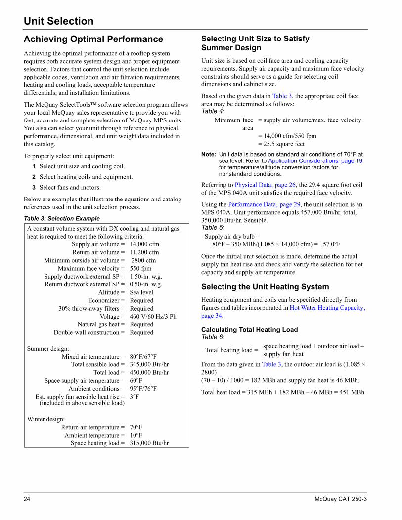
Table 3: Selection Example
A constant volume system with DX cooling and natural gas heat is required to meet the following criteria:
Supply air volume = 14,000 cfmReturn air volume = 11,200 cfm
Minimum outside air volume = 2800 cfmMaximum face velocity = 550 fpm
Supply ductwork external SP = 1.50-in. w.g.Return ductwork external SP = 0.50-in. w.g.
Altitude = Sea levelEconomizer = Required
30% throw-away filters = RequiredVoltage = 460 V/60 Hz/3 Ph
Natural gas heat = RequiredDouble-wall construction = Required
Summer design: Mixed air temperature = 80°F/67°F
Total sensible load = 345,000 Btu/hrTotal load = 450,000 Btu/hr
Space supply air temperature = 60°FAmbient conditions = 95°F/76°F
Est. supply fan sensible heat rise =(included in above sensible load)
3°F
Winter design: Return air temperature = 70°F
Ambient temperature = 10°FSpace heating load = 315,000 Btu/hr
Table 4: Minimum face
area= supply air volume/max. face velocity
= 14,000 cfm/550 fpm= 25.5 square feet
Table 5: Supply air dry bulb =
80°F – 350 MBh/(1.085 × 14,000 cfm) = 57.0°F
Table 6:
Total heating load =space heating load + outdoor air load – supply fan heat
24 McQuay CAT 250-3
Unit Selection
Selecting Fans and Motors
Fan and motor selections are based on total static pressure drop and design airflow. Total static pressure includes internal air pressure drops of unit components and external air pressure drops in supply and return ducts. Refer to Pressure Drops‚ page 36 for internal pressure drops of unit components.
When selecting unit fans and motors, use the fan curves provided in Figure 28, page 41 and Figure 29, page 42.
Select the motor size most closely above the application brake horsepower. (Example: For an application brake horsepower of 7 bhp, select a 7.5 hp motor). An oversized motor (large horsepower to load ratio) can greatly increase electric consumption due to the reduction in motor performance.
Exhaust Fan and Motor
Exhaust fans must be sized for maximum exhaust cfm and return duct ESP at those conditions. See “Fan Performance” on page 41. for more information.
Supply Fan and Motor
Since the system in Table 3 includes a return fan, the return duct static pressure drop is not added to the supply fan pressure drop. Therefore, the total static pressure for the supply fan in Table 3 is as follows:
Entering the MPS 040A fan curve at 14,000 cfm and 3.16-in. w.g., the required fan motor size is 15 hp operating at 1325 rpm. Fan brake horsepower is 12.9 horsepower.
The total fan and motor heat for the supply fan is as follows:
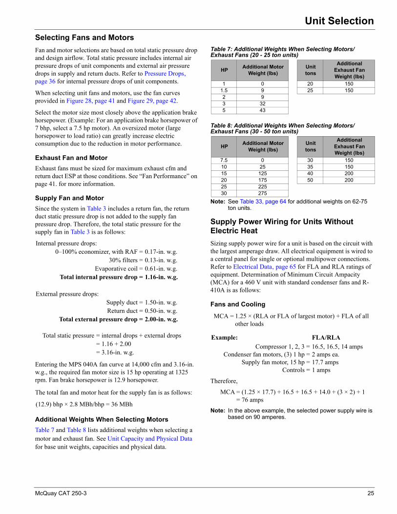
Additional Weights When Selecting Motors
Table 7 and Table 8 lists additional weights when selecting a motor and exhaust fan. See Unit Capacity and Physical Data for base unit weights, capacities and physical data.
Note: See Table 33, page 64 for additional weights on 62-75 ton units.
Supply Power Wiring for Units WithoutElectric Heat
Sizing supply power wire for a unit is based on the circuit with the largest amperage draw. All electrical equipment is wired to a central panel for single or optional multipower connections. Refer to Electrical Data‚ page 65 for FLA and RLA ratings of equipment. Determination of Minimum Circuit Ampacity (MCA) for a 460 V unit with standard condenser fans and R-410A is as follows:
Fans and Cooling
Therefore,
Note: In the above example, the selected power supply wire is based on 90 amperes.
Internal pressure drops:0–100% economizer, with RAF = 0.17-in. w.g.
30% filters = 0.13-in. w.g.Evaporative coil = 0.61-in. w.g.
Total internal pressure drop = 1.16-in. w.g.
External pressure drops:Supply duct = 1.50-in. w.g.Return duct = 0.50-in. w.g.
Total external pressure drop = 2.00-in. w.g.
Total static pressure = internal drops + external drops= 1.16 + 2.00= 3.16-in. w.g.
(12.9) bhp × 2.8 MBh/bhp = 36 MBh
Table 7: Additional Weights When Selecting Motors/Exhaust Fans (20 - 25 ton units)
HPAdditional Motor
Weight (lbs)Unit tons
Additional Exhaust Fan Weight (lbs)
1 0 20 1501.5 9 25 1502 93 325 43
Table 8: Additional Weights When Selecting Motors/Exhaust Fans (30 - 50 ton units)
HPAdditional Motor
Weight (lbs)Unit tons
Additional Exhaust Fan Weight (lbs)
7.5 0 30 15010 25 35 15015 125 40 20020 175 50 20025 22530 275
MCA = 1.25 × (RLA or FLA of largest motor) + FLA of all other loads
Example: FLA/RLA
Compressor 1, 2, 3 = 16.5, 16.5, 14 ampsCondenser fan motors, (3) 1 hp = 2 amps ea.
Supply fan motor, 15 hp = 17.7 ampsControls = 1 amps
MCA = (1.25 × 17.7) + 16.5 + 16.5 + 14.0 + (3 × 2) + 1= 76 amps
McQuay CAT 250-3 25

Physical Data
Physical DataUnit Capacity and Physical Data
Note: 1 Piping connections are given with a male outside diameter dimension, brazed connection.
Table 9: MPS 020E – 030E
ModelMPS
020E 025E 030ECooling PerformanceGross cooling capacity (tons) 21.7 25.3 30.0Nominal airflow (cfm) 8000 10,000 12,000EER 10.0 10.0 11.5IPLV 13.3 13.3 13.4Gas Heating PerformanceLow heat MBH (input/output)1 240/192 240/192 300/240Number of stages (low heat) 2 2 2Turndown (low heat)2 4:1 4:1 4:1Gas connection pipe size/qty (low heat) 3/4"/1 3/4"/1 3/4"/1High heat MBH (input/output)1 480/384 480/384 600/480Number of stages (high heat) 4 4 4Gas connection pipe size/qty (high heat) 3/4"/2 3/4"/2 3/4"/2Turndown (high heat)2 8:1 8:1 8:1Steady state efficiency 80% 80% 80%Hot Water Heating PerformanceFace area (sq ft) 12.25 12.25 19.25Rows/FPI (low heat) 1/14 1/14 1/12Coil model (low heat) 5WB 5WB 5WBConnection sizes/type (low heat)1 ODM Sweat ODM Sweat ODM SweatRows/FPI (high heat) 2/9 2/9 2/10Coil model (high heat) 5WS 5WS 5WSConnection sizes/type (high heat)1 ODM Sweat ODM Sweat ODM SweatElectric Heating PerformanceNumber of stages 4 4 4kW (low/medium/high heat) 36/54/72 36/54/72 54/72/90CompressorsType/number Scroll/3 Scroll/3 Scroll/3Number of stages 5 5 5Refrigerant R-410A R-410A R-410ACharge (lbs) Ckt1 - 11.5/Ckt2 - 7.5 Ckt1 - 10.5/Ckt2 - 11 Ckt1 - 19/Ckt2 - 10.2Evaporator CoilsRows 4 4 4FPI 13 13 12Face area (sq ft) 18.2 18.2 25.4Capacity control TXV TXV TXVCondenser CoilsFin type Enhanced Enhanced EnhancedFPI 18 18 18Face area (sq ft) 18.1/18.1 18.1/18.1 13.4/27.5Outdoor FansType Propeller Propeller PropellerNumber - diameter 2 - 26" 2 - 26" 3 - 26"Drive type/number of speeds Direct/1 Direct/1 Direct/1Indoor FansType AF - SWSI AF - SWSI AF - SWSINumber - diameter 1 - 20" 1 - 22" 1 - 24"Drive type Fixed sheave Fixed sheave Fixed sheaveIsolation 1" spring 1" spring 1" springNumber of motors 1 1 1Motor hp range 2 - 150 2 - 15 5 - 20Motor nominal rpm 1800 1800 1800Motor efficiency Premium Premium PremiumFiltersType 2", MERV 6Area (sq ft) 24 24 32Qty. - size 6 - 24" x 24" 6 - 24" x 24" 8 - 24" x 24"Total Unit Weight
Weight (lbs)3 Cooling Heating Cooling Heating Cooling Heating2955 3155 3055 3255 3610 3880
Curb
HeightCooling Heating Cooling Heating Cooling Heating
14" 24" 14" 24" 14" 24"Weight (lbs) 341 501 341 501 341 501
26 McQuay CAT 250-3
Physical Data
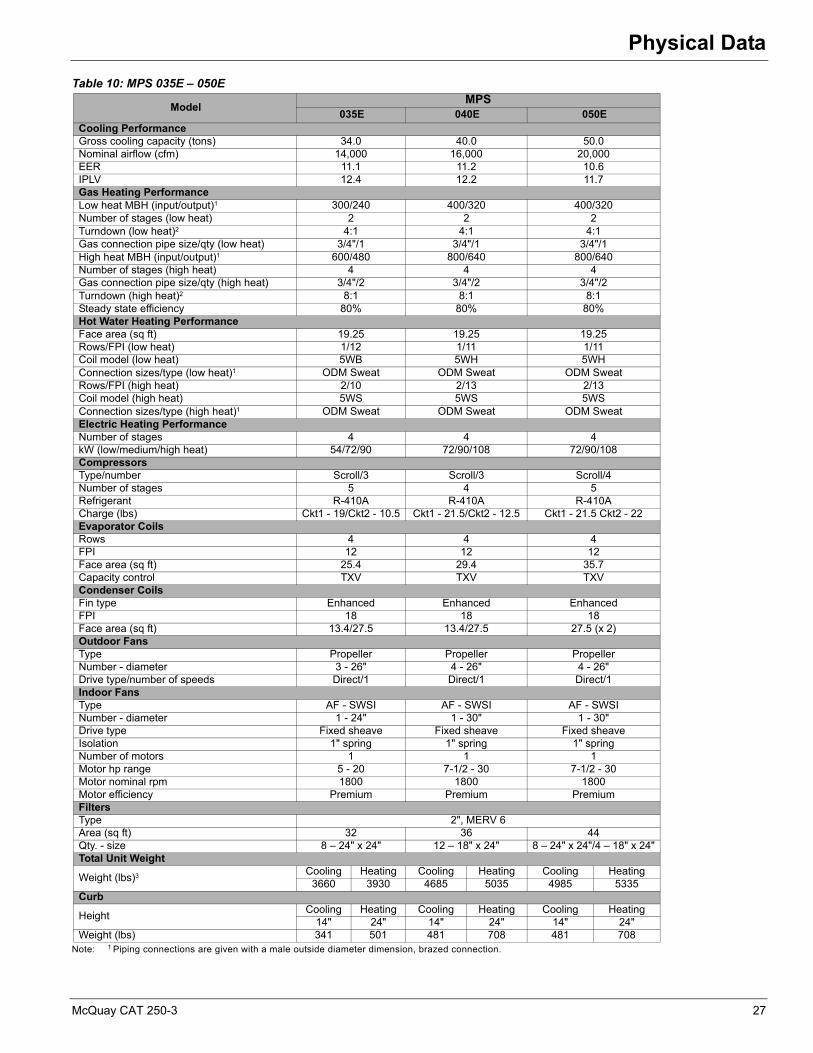
Note: 1 Piping connections are given with a male outside diameter dimension, brazed connection.
Table 10: MPS 035E – 050E
ModelMPS
035E 040E 050ECooling PerformanceGross cooling capacity (tons) 34.0 40.0 50.0Nominal airflow (cfm) 14,000 16,000 20,000EER 11.1 11.2 10.6IPLV 12.4 12.2 11.7Gas Heating PerformanceLow heat MBH (input/output)1 300/240 400/320 400/320Number of stages (low heat) 2 2 2Turndown (low heat)2 4:1 4:1 4:1Gas connection pipe size/qty (low heat) 3/4"/1 3/4"/1 3/4"/1High heat MBH (input/output)1 600/480 800/640 800/640Number of stages (high heat) 4 4 4Gas connection pipe size/qty (high heat) 3/4"/2 3/4"/2 3/4"/2Turndown (high heat)2 8:1 8:1 8:1Steady state efficiency 80% 80% 80%Hot Water Heating PerformanceFace area (sq ft) 19.25 19.25 19.25Rows/FPI (low heat) 1/12 1/11 1/11Coil model (low heat) 5WB 5WH 5WHConnection sizes/type (low heat)1 ODM Sweat ODM Sweat ODM SweatRows/FPI (high heat) 2/10 2/13 2/13Coil model (high heat) 5WS 5WS 5WSConnection sizes/type (high heat)1 ODM Sweat ODM Sweat ODM SweatElectric Heating PerformanceNumber of stages 4 4 4kW (low/medium/high heat) 54/72/90 72/90/108 72/90/108CompressorsType/number Scroll/3 Scroll/3 Scroll/4Number of stages 5 4 5Refrigerant R-410A R-410A R-410ACharge (lbs) Ckt1 - 19/Ckt2 - 10.5 Ckt1 - 21.5/Ckt2 - 12.5 Ckt1 - 21.5 Ckt2 - 22Evaporator CoilsRows 4 4 4FPI 12 12 12Face area (sq ft) 25.4 29.4 35.7Capacity control TXV TXV TXVCondenser CoilsFin type Enhanced Enhanced EnhancedFPI 18 18 18Face area (sq ft) 13.4/27.5 13.4/27.5 27.5 (x 2)Outdoor FansType Propeller Propeller PropellerNumber - diameter 3 - 26" 4 - 26" 4 - 26"Drive type/number of speeds Direct/1 Direct/1 Direct/1Indoor FansType AF - SWSI AF - SWSI AF - SWSINumber - diameter 1 - 24" 1 - 30" 1 - 30"Drive type Fixed sheave Fixed sheave Fixed sheaveIsolation 1" spring 1" spring 1" springNumber of motors 1 1 1Motor hp range 5 - 20 7-1/2 - 30 7-1/2 - 30Motor nominal rpm 1800 1800 1800Motor efficiency Premium Premium PremiumFiltersType 2", MERV 6Area (sq ft) 32 36 44Qty. - size 8 – 24" x 24" 12 – 18" x 24" 8 – 24" x 24"/4 – 18" x 24"Total Unit Weight
Weight (lbs)3 Cooling Heating Cooling Heating Cooling Heating3660 3930 4685 5035 4985 5335
Curb
HeightCooling Heating Cooling Heating Cooling Heating
14" 24" 14" 24" 14" 24"Weight (lbs) 341 501 481 708 481 708
McQuay CAT 250-3 27

Physical Data
Note: 1 Piping connections are given with a male outside diameter dimension, brazed connection.
Note: 2 Heating output is for standard conditions at sea level.
Table 11: MPS 062E – 075E
ModelMPS
062E 070E 075E
Cooling PerformanceNominal gross cooling capacity (tons) 62.0 70.0 75.0Nominal airflow (cfm) 24,000 26,000 28,000EER (standard coil/large coil) 10.0/10.3 9.7 9.3IPLV 13.0/13.0 13.1 12.0Gas Heating PerformanceLow heat MBH (input/output)1 500/400 500/400 500/400Gas connection pipe size/qty (low heat) 1"/1 1"/1 1"/1Medium heat MBH (input/output)1 600/480 600/480 800/640Gas connection pipe size/qty (medium heat) 1 1/4"/1 1 1/4"/1 1 1/4"/1High heat MBH (input/output)1 980/790 980/790 980/790Gas connection pipe size/qty (high heat) 1 1/4"/1 1 1/4"/1 1 1/4"/1Number of stages - all furnaces (high heat) Mod Mod ModTurndown - all furnaces (high heat)2 3:1 3:1 3:1Steady state efficiency - all furnaces 80% 80% 80%Hot Water Heating PerformanceFace area (sq ft) 29.7 29.7 29.7Type–rows (standard / high capacity) 5WH–1 / 5WS–2 5WH–1 / 5WS–2 5WH–1 / 5WS–2FPI 9 9 9Electric Heating PerformanceNumber of stages 4 4 4kW (low/medium/high heat) 100/120/160 100/120/160 100/120/160CompressorsType/number Scroll/4 Scroll/6 Scroll/6Number of stages 4 6 6Refrigerant R-410A R-410A R-410ACharge (lbs) Ckt1 - 33/Ckt2 - 33 Ckt1 - 36/Ckt2 - 36 Ckt1 - 36/Ckt2 - 36Evaporator CoilsRows 5 5 5FPI 10 10 10Face area (sq ft) 39.5 or 47.1 47.1 47.1Capacity control TXV TXV TXVCondenser CoilsFin type Enhanced Enhanced EnhancedFPI 18 18 18Face area (sq ft) 32.1 × 2 37.3 × 2 37.3 × 2Outdoor FansType Propeller Propeller PropellerNumber - diameter 6 - 26" 6 - 26" 8 - 26"Drive type/number of speeds Direct/1 Direct/1 Direct/1Indoor FansSWSI AF 1 - 44"DWDI AF 1 - 30" or 1 - 33"Drive type Variable sheaveIsolation 2" springNumber of motors 1Motor hp range 5 - 40Motor nominal rpm 1800Motor efficiency PremiumFilters
Qty. - type / sq. ft.Merv 6 angular (7) 16 × 20 and (21) 16 × 25 / 73 sq. ft.
6" Merv 11 or 12" Merv 14(4) 12 × 24 and (8) 24 × 24 / 40 sq. ft. standard air flow
(8) 12 × 24 and (8) 24 × 24 / 48 sq. ft. high air flow
28 McQuay CAT 250-3

Performance Data
Performance DataCooling Capacity
Note: THC = Total Heat Capacity (gross), SHC = Sensible Heat Capacity (gross), kW = Total compressor kWCooling capacities are for standard conditions at sea level.
Note: THC = Total Heat Capacity (gross), SHC = Sensible Heat Capacity (gross), kW = Total compressor kWCooling capacities are for standard conditions at sea level.
Table 12: MPS 020E Cooling Capacities
CFMEntering Air
Temperature (°F)Ambient Air Temperature (°F)
85° 95° 105° 115°
DB WB THC SHC kW THC SHC kW THC SHC kW THC SHC kW
8000
7561 256 222 17.3 244 216 19.3 232 211 21.5 217 204 23.967 282 167 17.6 268 162 19.7 254 156 21.9 238 150 24.373 312 111 17.9 297 106 20.0 281 101 22.2 264 95 24.6
8061 261 261 17.4 251 251 19.4 240 240 21.6 228 228 24.167 282 210 17.6 269 205 19.6 255 200 21.8 240 194 24.373 311 155 17.9 296 149 20.0 281 144 22.2 264 139 24.6
8561 276 276 17.6 265 265 19.6 254 254 21.8 241 241 24.367 285 254 17.7 271 248 19.7 257 242 21.9 243 235 24.373 311 198 17.9 296 193 20.0 281 188 22.2 264 182 24.6
7000
7561 251 207 17.3 239 202 19.3 227 196 21.5 213 189 23.967 277 158 17.6 264 153 19.6 250 148 21.8 235 142 24.273 306 109 17.9 292 104 19.9 277 99 22.1 260 93 24.5
8061 253 244 17.3 242 238 19.3 231 231 21.5 219 219 24.067 276 196 17.6 263 191 19.6 250 186 21.8 235 180 24.273 306 147 17.9 291 142 19.9 276 137 22.1 260 131 24.6
8561 265 265 17.4 255 255 19.5 244 244 21.7 232 232 24.267 278 235 17.6 266 230 19.6 252 224 21.8 237 218 24.273 306 185 17.9 291 180 19.9 276 175 22.1 260 169 24.6
5500
7561 239 183 17.2 229 178 19.1 217 172 21.3 204 166 23.767 265 144 17.5 254 139 19.5 241 134 21.6 226 128 24.173 294 105 17.8 281 100 19.8 267 95 22.0 252 89 24.4
8061 241 214 17.2 230 208 19.2 219 203 21.3 206 196 23.767 265 175 17.4 254 170 19.5 241 164 21.7 226 158 24.173 294 135 17.8 281 130 19.8 267 125 22.0 251 120 24.4
8561 244 243 17.2 235 235 19.2 225 225 21.4 215 215 23.967 265 205 17.5 254 200 19.5 241 195 21.7 227 189 24.173 294 165 17.8 280 160 19.8 266 155 22.0 251 150 24.4
Table 13: MPS 025E Cooling Capacities
CFMEntering Air
Temperature (°F)Ambient Air Temperature (°F)
85° 95° 105° 115°
DB WB THC SHC kW THC SHC kW THC SHC kW THC SHC kW
10000
7561 296 264 20.8 283 258 23.1 268 251 25.7 252 243 28.767 325 197 21.4 310 191 23.7 293 185 26.3 275 178 29.273 359 128 22.0 342 123 24.3 324 117 26.9 304 110 29.9
8061 305 305 21.0 293 293 23.3 280 280 26.0 266 266 29.067 325 251 21.4 310 245 23.7 294 239 26.3 276 232 29.273 358 182 22.0 341 176 24.3 323 170 27.0 303 164 29.9
8561 322 322 21.3 310 310 23.7 296 296 26.3 281 281 29.467 328 303 21.4 314 296 23.8 298 289 26.4 281 279 29.473 358 236 22.0 341 230 24.3 324 224 26.9 304 218 29.9
8750
7561 290 247 20.7 277 240 23.0 263 234 25.6 247 227 28.567 319 187 21.3 305 181 23.6 289 175 26.2 271 168 29.173 353 126 21.9 337 120 24.2 319 114 26.8 300 108 29.8
8061 295 291 20.8 283 282 23.1 271 271 25.8 257 257 28.867 319 234 21.3 305 228 23.6 289 222 26.2 272 215 29.173 352 173 21.9 336 167 24.2 318 161 26.8 299 155 29.8
8561 310 310 21.1 299 299 23.4 286 286 26.1 271 271 29.167 321 281 21.3 307 275 23.6 292 268 26.2 274 261 29.273 352 220 21.9 336 215 24.2 319 209 26.8 300 202 29.8
6875
7561 278 218 20.5 266 212 22.8 252 206 25.4 237 199 28.367 308 170 21.0 294 165 23.3 279 158 26.0 262 152 28.973 341 121 21.6 326 116 24.0 309 110 26.6 291 104 29.6
8061 279 256 20.5 268 250 22.8 255 243 25.4 240 235 28.467 307 208 21.0 294 202 23.4 279 196 26.0 262 189 28.973 341 159 21.6 325 153 24.0 309 147 26.6 291 141 29.6
8561 287 287 20.7 276 276 23.0 265 265 25.7 253 253 28.767 308 245 21.0 295 240 23.4 280 234 26.0 264 227 29.073 340 196 21.7 325 191 24.0 308 185 26.6 290 178 29.6
McQuay CAT 250-3 29
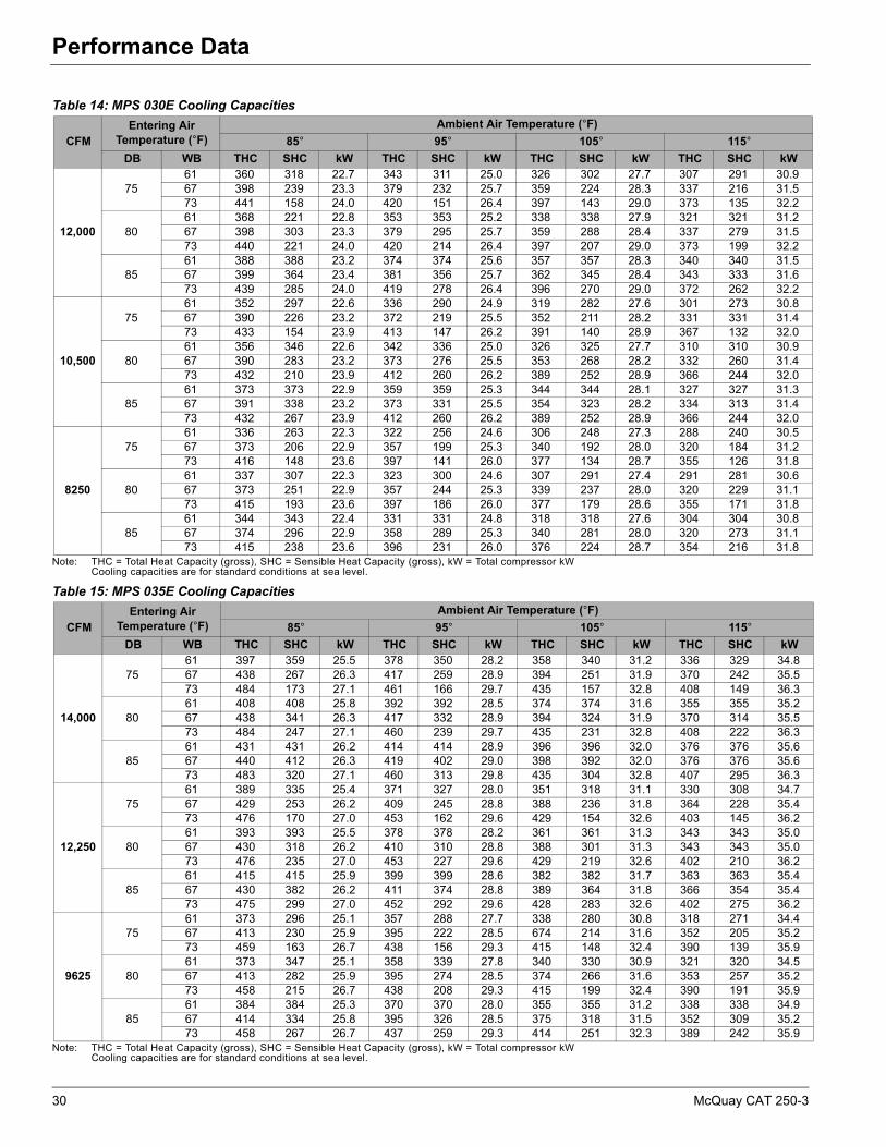
Performance Data
Note: THC = Total Heat Capacity (gross), SHC = Sensible Heat Capacity (gross), kW = Total compressor kWCooling capacities are for standard conditions at sea level.
Note: THC = Total Heat Capacity (gross), SHC = Sensible Heat Capacity (gross), kW = Total compressor kWCooling capacities are for standard conditions at sea level.
Table 14: MPS 030E Cooling Capacities
CFMEntering Air
Temperature (°F)Ambient Air Temperature (°F)
85° 95° 105° 115°
DB WB THC SHC kW THC SHC kW THC SHC kW THC SHC kW
12,000
7561 360 318 22.7 343 311 25.0 326 302 27.7 307 291 30.967 398 239 23.3 379 232 25.7 359 224 28.3 337 216 31.573 441 158 24.0 420 151 26.4 397 143 29.0 373 135 32.2
8061 368 221 22.8 353 353 25.2 338 338 27.9 321 321 31.267 398 303 23.3 379 295 25.7 359 288 28.4 337 279 31.573 440 221 24.0 420 214 26.4 397 207 29.0 373 199 32.2
8561 388 388 23.2 374 374 25.6 357 357 28.3 340 340 31.567 399 364 23.4 381 356 25.7 362 345 28.4 343 333 31.673 439 285 24.0 419 278 26.4 396 270 29.0 372 262 32.2
10,500
7561 352 297 22.6 336 290 24.9 319 282 27.6 301 273 30.867 390 226 23.2 372 219 25.5 352 211 28.2 331 331 31.473 433 154 23.9 413 147 26.2 391 140 28.9 367 132 32.0
8061 356 346 22.6 342 336 25.0 326 325 27.7 310 310 30.967 390 283 23.2 373 276 25.5 353 268 28.2 332 260 31.473 432 210 23.9 412 260 26.2 389 252 28.9 366 244 32.0
8561 373 373 22.9 359 359 25.3 344 344 28.1 327 327 31.367 391 338 23.2 373 331 25.5 354 323 28.2 334 313 31.473 432 267 23.9 412 260 26.2 389 252 28.9 366 244 32.0
8250
7561 336 263 22.3 322 256 24.6 306 248 27.3 288 240 30.567 373 206 22.9 357 199 25.3 340 192 28.0 320 184 31.273 416 148 23.6 397 141 26.0 377 134 28.7 355 126 31.8
8061 337 307 22.3 323 300 24.6 307 291 27.4 291 281 30.667 373 251 22.9 357 244 25.3 339 237 28.0 320 229 31.173 415 193 23.6 397 186 26.0 377 179 28.6 355 171 31.8
8561 344 343 22.4 331 331 24.8 318 318 27.6 304 304 30.867 374 296 22.9 358 289 25.3 340 281 28.0 320 273 31.173 415 238 23.6 396 231 26.0 376 224 28.7 354 216 31.8
Table 15: MPS 035E Cooling Capacities
CFMEntering Air
Temperature (°F)Ambient Air Temperature (°F)
85° 95° 105° 115°
DB WB THC SHC kW THC SHC kW THC SHC kW THC SHC kW
14,000
7561 397 359 25.5 378 350 28.2 358 340 31.2 336 329 34.867 438 267 26.3 417 259 28.9 394 251 31.9 370 242 35.573 484 173 27.1 461 166 29.7 435 157 32.8 408 149 36.3
8061 408 408 25.8 392 392 28.5 374 374 31.6 355 355 35.267 438 341 26.3 417 332 28.9 394 324 31.9 370 314 35.573 484 247 27.1 460 239 29.7 435 231 32.8 408 222 36.3
8561 431 431 26.2 414 414 28.9 396 396 32.0 376 376 35.667 440 412 26.3 419 402 29.0 398 392 32.0 376 376 35.673 483 320 27.1 460 313 29.8 435 304 32.8 407 295 36.3
12,250
7561 389 335 25.4 371 327 28.0 351 318 31.1 330 308 34.767 429 253 26.2 409 245 28.8 388 236 31.8 364 228 35.473 476 170 27.0 453 162 29.6 429 154 32.6 403 145 36.2
8061 393 393 25.5 378 378 28.2 361 361 31.3 343 343 35.067 430 318 26.2 410 310 28.8 388 301 31.3 343 343 35.073 476 235 27.0 453 227 29.6 429 219 32.6 402 210 36.2
8561 415 415 25.9 399 399 28.6 382 382 31.7 363 363 35.467 430 382 26.2 411 374 28.8 389 364 31.8 366 354 35.473 475 299 27.0 452 292 29.6 428 283 32.6 402 275 36.2
9625
7561 373 296 25.1 357 288 27.7 338 280 30.8 318 271 34.467 413 230 25.9 395 222 28.5 674 214 31.6 352 205 35.273 459 163 26.7 438 156 29.3 415 148 32.4 390 139 35.9
8061 373 347 25.1 358 339 27.8 340 330 30.9 321 320 34.567 413 282 25.9 395 274 28.5 374 266 31.6 353 257 35.273 458 215 26.7 438 208 29.3 415 199 32.4 390 191 35.9
8561 384 384 25.3 370 370 28.0 355 355 31.2 338 338 34.967 414 334 25.8 395 326 28.5 375 318 31.5 352 309 35.273 458 267 26.7 437 259 29.3 414 251 32.3 389 242 35.9
30 McQuay CAT 250-3

Performance Data
Note: THC = Total Heat Capacity (gross), SHC = Sensible Heat Capacity (gross), kW = Total compressor kWCooling capacities are for standard conditions at sea level.
Note: THC = Total Heat Capacity (gross), SHC = Sensible Heat Capacity (gross), kW = Total compressor kWCooling capacities are for standard conditions at sea level.
Table 16: MPS 040E Cooling Capacities
CFMEntering Air
Temperature (°F)Ambient Air Temperature (°F)
85° 95° 105° 115°
DB WB THC SHC kW THC SHC kW THC SHC kW THC SHC kW
16,000
7561 442 404 27.7 421 394 30.6 399 382 33.9 377 367 37.767 487 300 28.5 464 292 31.3 440 283 34.6 412 273 38.473 539 194 29.4 513 185 32.2 485 176 35.4 455 166 39.2
8061 456 456 28.0 438 438 30.9 419 419 34.2 397 397 38.167 487 384 28.5 465 376 31.3 439 366 34.6 413 355 38.473 538 278 29.4 512 269 32.2 485 260 35.4 455 250 39.2
8561 482 482 28.4 463 463 31.3 443 443 34.6 421 421 38.567 490 463 28.6 470 451 31.4 446 436 34.7 421 419 38.673 537 361 29.4 512 353 32.2 484 344 35.4 454 334 39.2
14,000
7561 432 377 27.6 413 368 30.4 392 358 33.7 368 347 37.667 478 284 28.4 456 275 31.2 432 266 34.4 406 257 38.373 530 189 29.2 505 181 32.0 478 172 35.3 449 162 39.1
8061 440 437 27.7 422 422 30.6 404 404 33.9 384 384 37.967 479 359 28.4 457 350 31.2 432 341 34.5 406 330 38.373 529 263 29.2 505 255 32.0 478 246 35.3 449 236 39.1
8561 464 464 28.1 447 447 31.0 428 428 34.4 406 406 38.367 480 431 28.4 458 422 31.2 435 411 34.5 411 396 38.473 529 338 29.2 504 329 32.0 477 320 35.3 448 310 39.1
11,000
7561 415 333 27.2 397 325 30.1 377 316 33.4 355 306 37.367 460 258 28.1 439 250 30.9 417 241 34.2 393 231 38.073 511 182 28.9 488 174 31.7 463 165 35.0 436 155 38.8
8061 416 391 27.3 399 381 30.1 380 369 33.5 360 355 37.467 460 318 28.0 440 309 30.9 417 300 34.2 393 290 38.073 511 241 28.9 488 233 31.7 463 224 35.0 435 215 38.8
8561 430 430 27.5 414 414 30.4 397 397 33.8 379 379 37.867 460 377 28.0 440 368 30.9 418 359 34.2 393 349 38.073 510 300 28.9 487 292 31.7 461 283 35.0 434 274 38.8
Table 17: MPS 050E Cooling Capacities
CFMEntering Air
Temperature (°F)Ambient Air Temperature (°F)
85° 95° 105° 115°
DB WB THC SHC kW THC SHC kW THC SHC kW THC SHC kW
20,000
7561 568 512 38.0 540 499 42.0 512 486 46.6 480 470 52.067 625 381 39.2 595 370 43.1 563 358 47.6 528 345 53.073 691 248 40.5 657 236 44.4 621 224 48.9 582 212 54.2
8061 583 583 38.4 560 560 42.4 534 534 47.1 506 506 52.667 626 486 39.2 596 475 43.1 563 462 47.7 528 448 53.073 691 352 40.5 657 341 44.4 620 329 48.9 581 316 54.2
8561 616 616 39.1 592 592 43.1 566 566 47.7 537 537 53.267 628 587 39.3 599 574 43.2 567 559 47.8 537 537 53.273 689 457 40.5 656 446 44.4 620 434 48.9 580 421 54.3
17,500
7561 557 479 37.8 531 467 41.7 502 453 46.3 470 439 51.867 614 361 39.0 585 349 42.9 553 337 47.5 520 325 52.873 680 242 40.2 647 231 44.2 612 219 48.7 574 207 54.0
8061 563 562 37.9 540 540 42.0 516 516 46.7 490 490 52.267 615 454 39.0 585 443 42.9 554 430 47.5 519 417 52.873 679 335 40.2 647 324 44.2 611 312 48.7 573 299 54.0
8561 593 593 38.6 570 570 42.6 545 545 47.3 518 518 52.867 615 545 39.0 587 533 43.0 556 520 47.5 523 506 52.973 678 427 40.2 644 416 44.2 610 404 48.7 572 392 54.1
13,750
7561 534 423 37.3 510 412 41.3 483 400 45.9 455 387 51.467 591 329 38.5 564 318 42.5 534 306 47.1 502 293 52.573 656 233 39.8 625 222 43.7 592 211 48.3 556 198 53.7
8061 534 496 37.3 511 485 41.3 486 472 46.0 458 456 51.567 591 403 38.5 564 392 42.5 534 380 47.1 503 367 52.573 655 307 39.8 625 296 43.7 592 285 48.3 556 272 53.7
8561 549 549 37.7 529 529 41.7 507 507 46.5 482 482 52.167 592 477 38.5 565 466 42.5 534 453 47.1 503 441 52.573 654 381 39.7 624 370 43.7 591 358 48.3 555 346 53.6
McQuay CAT 250-3 31
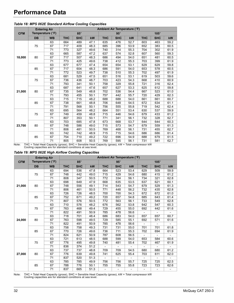
Performance Data
Note: THC = Total Heat Capacity (gross), SHC = Sensible Heat Capacity (gross), kW = Total compressor kWCooling capacities are for standard conditions at sea level.
Note: THC = Total Heat Capacity (gross), SHC = Sensible Heat Capacity (gross), kW = Total compressor kWCooling capacities are for standard conditions at sea level.
Table 18: MPS 062E Standard Airflow Cooling Capacities
CFMEntering Air
Temperature (°F)Ambient Air Temperature (°F)
85° 95° 105°
DB WB THC SHC kW THC SHC kW THC SHC kW
18,000
7563 664 489 47.1 635 476 52.7 603 463 59.267 717 409 48.3 685 396 53.9 652 383 60.571 773 327 49.6 740 314 55.3 704 302 61.9
8063 665 587 47.2 637 574 52.8 607 560 59.367 717 507 48.3 686 494 54.0 651 481 60.571 773 425 49.6 738 412 55.3 703 399 61.9
8563 677 677 47.4 654 654 53.1 629 629 59.867 717 604 48.3 686 591 54.0 653 578 60.571 772 523 49.7 738 510 55.3 702 497 61.9
21,000
7563 681 529 47.5 651 516 53.1 619 503 59.667 736 436 48.7 703 423 54.3 668 410 60.971 793 341 50.1 758 329 55.8 721 316 62.4
8063 687 641 47.6 657 627 53.3 625 612 59.867 735 549 48.8 702 536 54.4 667 523 61.071 793 455 50.1 757 442 55.7 720 429 62.3
8563 715 715 48.2 688 688 54.0 661 661 60.767 738 661 48.8 706 648 54.5 672 634 61.171 791 568 50.1 756 555 55.8 719 542 62.4
23,700
7563 695 564 48.2 664 551 53.4 630 537 59.967 749 459 48.8 715 446 54.6 679 433 61.271 807 353 50.1 771 341 56.1 732 328 62.7
8063 703 685 47.8 673 668 53.7 644 644 60.367 748 586 49.0 715 573 54.7 679 559 61.371 806 481 50.5 769 468 56.1 731 455 62.7
8563 742 742 48.9 715 715 54.6 686 686 61.467 754 710 49.2 722 696 54.9 688 679 61.571 805 608 50.5 769 595 56.1 731 581 62.7
Table 19: MPS 062E High Airflow Cooling Capacities
CFMEntering Air
Temperature (°F)Ambient Air Temperature (°F)
85° 95° 105°
DB WB THC SHC kW THC SHC kW THC SHC kW
21,000
7563 694 536 47.8 664 523 53.4 629 509 59.967 748 442 49.0 715 429 54.6 680 415 61.271 808 347 50.5 772 334 56.1 734 321 62.8
8063 698 649 47.9 668 635 53.5 637 621 60.167 748 556 49.1 714 543 54.7 679 529 61.371 806 461 50.5 771 448 56.2 732 435 62.8
8563 726 726 48.5 700 700 54.3 672 672 61.067 752 671 49.2 720 657 54.8 685 643 61.471 807 576 50.5 772 563 56.1 733 549 62.8
24,000
7563 710 576 48.2 676 562 53.8 642 547 60.367 763 468 49.4 729 455 55.0 692 442 61.671 822 491 50.9 785 478 56.6 - - -
8063 718 701 48.4 686 683 54.0 657 657 60.767 763 598 49.5 729 585 55.1 692 571 61.671 822 491 50.9 785 478 56.6 - - -
8563 758 758 49.3 731 731 55.0 701 701 61.867 770 726 49.6 736 711 55.3 702 694 61.971 824 621 50.9 787 608 56.5 - - -
27,000
7563 721 613 48.5 688 599 54.0 653 584 60.667 776 495 49.8 740 481 55.4 702 467 61.971 836 374 51.2 - - - - - -
8063 737 737 48.8 709 709 54.5 680 680 61.267 776 639 49.8 741 625 55.4 703 611 62.071 837 520 51.3 - - - - - -
8563 785 785 49.9 756 756 55.7 725 725 62.567 788 776 50.1 755 755 55.8 723 723 62.671 837 665 51.3 - - - - - -
32 McQuay CAT 250-3

Performance Data
Note: THC = Total Heat Capacity (gross), SHC = Sensible Heat Capacity (gross), kW = Total compressor kWCooling capacities are for standard conditions at sea level.
Note: THC = Total Heat Capacity (gross), SHC = Sensible Heat Capacity (gross), kW = Total compressor kWCooling capacities are for standard conditions at sea level.
Table 20: MPS 070E High Airflow Cooling Capacities
CFMEntering Air
Temperature (°F)Ambient Air Temperature (°F)
85° 95° 105°
DB WB THC SHC kW THC SHC kW THC SHC kW
22,000
7563 784 586 57.6 743 568 64.7 697 548 73.167 838 484 58.8 794 467 66.0 746 448 74.471 896 381 60.1 849 364 67.5 796 465 75.9
8063 788 705 57.6 746 687 64.8 702 667 73.267 838 604 58.8 794 586 66.1 747 568 74.571 894 500 60.1 847 484 67.5 796 465 75.9
8563 804 804 57.9 770 770 65.4 732 732 74.067 839 723 58.8 796 705 66.2 749 686 74.671 894 621 60.2 847 603 67.6 796 585 75.9
26,000
7563 803 637 58.0 761 619 65.2 714 599 73.667 857 518 59.2 812 501 66.5 762 482 74.971 915 399 60.6 867 382 68.0 814 364 76.4
8063 809 774 58.1 768 753 65.4 725 725 73.867 858 659 59.3 813 641 66.6 763 622 75.071 915 539 60.6 866 522 68.0 813 504 76.4
8563 845 845 58.9 808 808 66.4 767 767 75.067 861 796 59.4 819 778 66.8 769 755 75.271 913 679 60.7 865 662 68.1 812 643 76.4
30,000
7563 819 687 58.3 774 668 65.6 726 648 73.967 873 552 59.6 826 535 66.9 775 516 75.271 930 415 61.0 880 399 68.4 - - -
8063 831 830 58.6 793 793 66.0 751 751 74.567 874 712 59.7 827 694 67.0 776 674 75.371 929 576 61.0 879 559 68.4 - - -
8563 877 877 59.7 838 838 67.2 795 795 75.867 881 862 59.9 836 835 67.3 793 793 75.971 928 735 61.1 879 718 68.5 - - -
Table 21: MPS 075E High Airflow Cooling Capacities
CFMEntering Air
Temperature (°F)Ambient Air Temperature (°F)
85° 95° 105°
DB WB THC SHC kW THC SHC kW THC SHC kW
22,000
7563 851 615 65.0 809 597 72.8 765 577 81.767 910 513 66.3 865 495 74.2 817 476 83.271 970 409 67.9 922 391 75.8 872 372 84.8
8063 853 735 65.0 811 716 72.8 768 697 81.867 909 632 66.3 864 614 74.2 817 596 83.271 969 528 67.9 922 511 75.8 871 492 84.8
8563 861 850 65.2 822 822 73.2 787 787 82.367 910 752 66.4 866 734 74.3 819 715 83.371 968 648 67.9 921 630 75.8 871 612 84.9
26,000
7563 873 667 65.5 831 649 73.3 785 629 82.267 932 547 66.9 885 529 74.8 836 510 83.771 994 426 68.5 944 409 76.4 891 390 85.4
8063 878 806 65.6 835 786 73.4 789 765 82.467 930 687 66.9 885 670 74.8 836 650 83.771 992 566 68.5 942 549 76.4 890 530 85.4
8563 903 903 66.2 866 866 74.2 826 826 83.467 935 827 67.1 889 808 75.0 840 788 84.071 991 707 68.6 942 689 76.5 890 671 85.5
30,000
7563 891 717 65.9 847 699 73.7 799 679 82.667 949 581 67.4 901 563 75.2 850 544 84.271 1011 443 69.0 958 425 76.9 904 407 85.9
8063 899 871 66.1 855 847 74.0 813 813 83.067 949 741 67.4 901 723 75.3 850 703 84.371 1008 604 69.0 957 586 76.9 903 567 85.8
8563 940 940 67.1 900 900 75.2 858 858 84.467 954 897 67.6 907 875 75.5 858 851 84.671 1009 764 69.0 958 746 77.0 905 727 86.0
McQuay CAT 250-3 33

Performance Data
Electric Heating Capacity
Note: * Temperature rise is calculated at nominal cfm
Hot Water Heating Capacity
Note: * Temperature rise is calculated at nominal cfm
Table 22: MPS 020E – 075E Electric Heating Capacities
UnitNomcfm
StagesLow Heat Medium Heat High Heat
kW MBhDelta
T*Min. cfm
kW MBhDelta
T*Min. cfm
kW MBhDelta
T*Min. cfm
020E 8000 4 36 123 14.2 1900 54 184 21.2 2900 72 246 28.3 3800025E 10,000 4 36 123 11.4 1900 54 184 17.0 2900 72 246 22.7 3800030E 12,000 4 54 184 14.2 2900 72 246 19.0 3800 90 307 23.7 4800035E 14,000 4 54 184 12.2 2900 72 246 16.3 3800 90 307 20.3 4800040E 16,000 4 72 246 14.2 3800 90 307 17.8 4800 108 369 21.3 5700050E 20,000 4 72 246 11.4 3800 90 307 14.2 4800 108 369 17.1 5700062E 24,000 4 100 342 13.1 14,000 160 546 21.0 14,000 200 684 26.3 14,000070E 26,000 4 100 342 12.1 14,000 160 546 19.6 14,000 200 684 24.2 14,000075E 28,000 4 100 342 11.3 14,000 160 546 18.0 14,000 200 684 22.5 14,000
Table 23: MPS 020E – 050E Hot Water Heating Capacities
UnitNomcfm
Low Heat High Heat
MBhDelta
T*GPM
Min. cfm
Inlet dia.
MBhDelta
T*GPM
Min. cfm
Inlet dia.
020E 8000 193 22.2 17.3 1850 1.5 368 42.4 35.0 1850 1.5025E 10,000 218 20.1 21.6 1850 1.5 433 39.9 45.0 1850 1.5030E 12,000 297 22.8 29.0 2900 1.5 553 42.5 52.2 2900 2.5035E 14,000 315 20.7 30.5 2900 1.5 614 40.4 60.8 2900 2.5040E 16,000 389 22.4 34.0 2900 1.5 758 43.7 69.5 2900 2.5050E 20,000 446 20.6 43.4 2900 1.5 878 40.5 87.0 2900 2.5
34 McQuay CAT 250-3
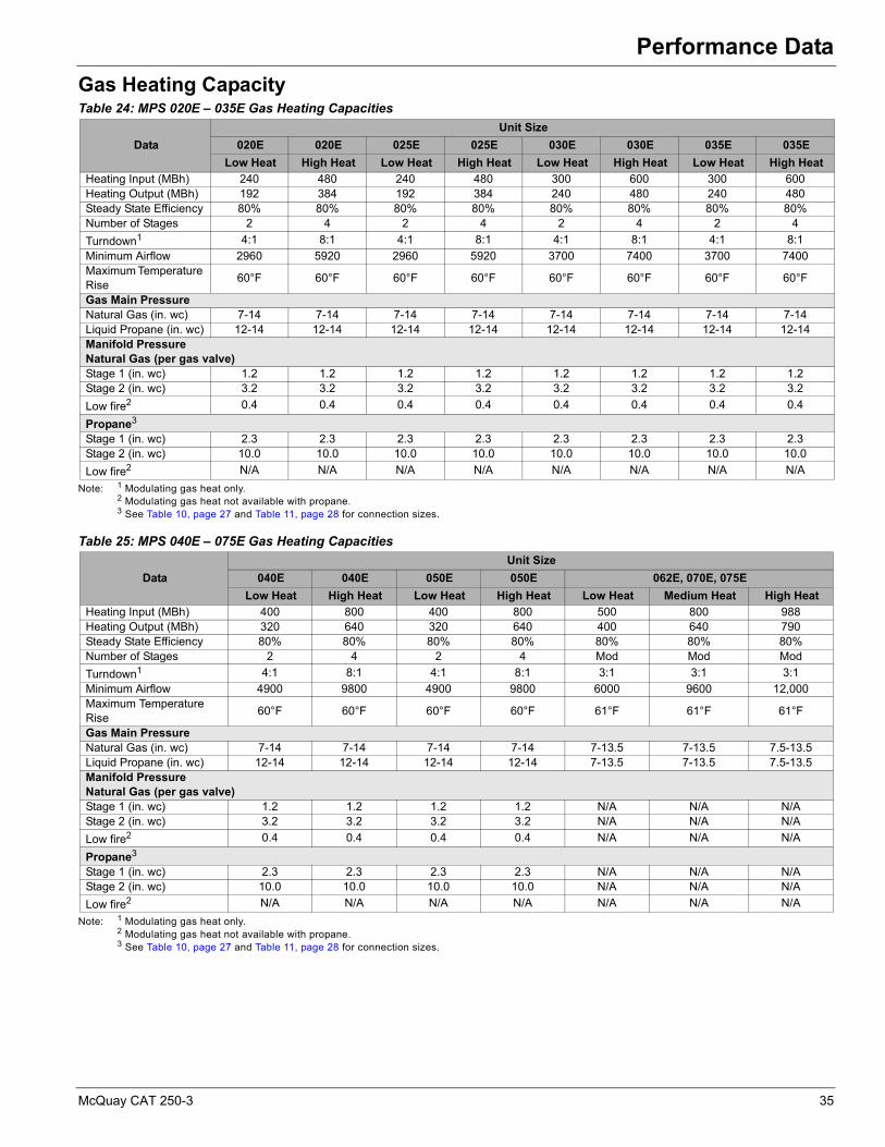
Performance Data
Gas Heating Capacity
Note: 1 Modulating gas heat only.2 Modulating gas heat not available with propane.3 See Table 10, page 27 and Table 11, page 28 for connection sizes.
Note: 1 Modulating gas heat only.2 Modulating gas heat not available with propane.3 See Table 10, page 27 and Table 11, page 28 for connection sizes.
Table 24: MPS 020E – 035E Gas Heating Capacities
Data
Unit Size
020E 020E 025E 025E 030E 030E 035E 035E
Low Heat High Heat Low Heat High Heat Low Heat High Heat Low Heat High Heat
Heating Input (MBh) 240 480 240 480 300 600 300 600Heating Output (MBh) 192 384 192 384 240 480 240 480Steady State Efficiency 80% 80% 80% 80% 80% 80% 80% 80%Number of Stages 2 4 2 4 2 4 2 4
Turndown1 4:1 8:1 4:1 8:1 4:1 8:1 4:1 8:1
Minimum Airflow 2960 5920 2960 5920 3700 7400 3700 7400Maximum Temperature Rise
60°F 60°F 60°F 60°F 60°F 60°F 60°F 60°F
Gas Main PressureNatural Gas (in. wc) 7-14 7-14 7-14 7-14 7-14 7-14 7-14 7-14Liquid Propane (in. wc) 12-14 12-14 12-14 12-14 12-14 12-14 12-14 12-14Manifold PressureNatural Gas (per gas valve)Stage 1 (in. wc) 1.2 1.2 1.2 1.2 1.2 1.2 1.2 1.2Stage 2 (in. wc) 3.2 3.2 3.2 3.2 3.2 3.2 3.2 3.2
Low fire2 0.4 0.4 0.4 0.4 0.4 0.4 0.4 0.4
Propane3
Stage 1 (in. wc) 2.3 2.3 2.3 2.3 2.3 2.3 2.3 2.3Stage 2 (in. wc) 10.0 10.0 10.0 10.0 10.0 10.0 10.0 10.0
Low fire2 N/A N/A N/A N/A N/A N/A N/A N/A
Table 25: MPS 040E – 075E Gas Heating Capacities
Data
Unit Size
040E 040E 050E 050E 062E, 070E, 075E
Low Heat High Heat Low Heat High Heat Low Heat Medium Heat High Heat
Heating Input (MBh) 400 800 400 800 500 800 988Heating Output (MBh) 320 640 320 640 400 640 790Steady State Efficiency 80% 80% 80% 80% 80% 80% 80%Number of Stages 2 4 2 4 Mod Mod Mod
Turndown1 4:1 8:1 4:1 8:1 3:1 3:1 3:1
Minimum Airflow 4900 9800 4900 9800 6000 9600 12,000Maximum Temperature Rise
60°F 60°F 60°F 60°F 61°F 61°F 61°F
Gas Main PressureNatural Gas (in. wc) 7-14 7-14 7-14 7-14 7-13.5 7-13.5 7.5-13.5Liquid Propane (in. wc) 12-14 12-14 12-14 12-14 7-13.5 7-13.5 7.5-13.5Manifold PressureNatural Gas (per gas valve)Stage 1 (in. wc) 1.2 1.2 1.2 1.2 N/A N/A N/AStage 2 (in. wc) 3.2 3.2 3.2 3.2 N/A N/A N/A
Low fire2 0.4 0.4 0.4 0.4 N/A N/A N/A
Propane3
Stage 1 (in. wc) 2.3 2.3 2.3 2.3 N/A N/A N/AStage 2 (in. wc) 10.0 10.0 10.0 10.0 N/A N/A N/A
Low fire2 N/A N/A N/A N/A N/A N/A N/A
McQuay CAT 250-3 35
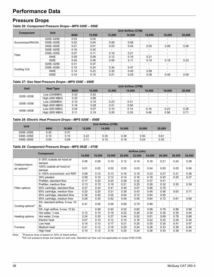
Performance Data
Pressure Drops
Note: 1Pressure drop is based on 30% of listed airflow.2DX coil pressure drops are based on wet coils. Standard air flow coil not applicable on sizes 070E-075E.
Table 26: Component Pressure Drops—MPS 020E – 050E
Component UnitUnit Airflow (CFM)
8000 10,000 12,000 14,000 16,000 18,000 20,000
Economizer/RA/OA020E–025E 0.03 0.05 - - - - -030E–035E 0.02 0.04 0.06 0.08 - - -040E–050E 0.01 0.01 0.03 0.04 0.05 0.06 0.08
Filter
020E–025E 0.16 0.25 - - - - -030E–035E 0.07 0.11 0.16 0.21 - - -
040E 0.05 0.08 0.12 0.16 0.21 - -050E 0.04 0.06 0.08 0.11 0.15 0.19 0.23
Cooling Coil
020E–025E 0.31 0.47 - - - - -030E–035E 0.15 0.24 0.34 0.47 - - -
040E 0.14 0.22 0.32 0.45 0.58 - -050E 0.10 0.15 0.21 0.29 0.38 0.48 0.59
Table 27: Gas Heat Pressure Drops—MPS 020E – 050E
Unit Heat TypeUnit Airflow (CFM)
8000 10,000 12,000 14,000 16,000 18,000 20,000
020E–025ELow (240MBH) 0.33 0.52 - - - - -High (480 MBH) 0.35 0.86 - - - - -
030E–035ELow (300MBH) 0.10 0.16 0.23 0.31 - - -High (600 MBH) 0.18 0.28 0.41 0.56 - - -
040E–050ELow (400 MBH) 0.04 0.07 0.10 0.14 0.18 0.23 0.28High (800 MBH) 0.11 0.18 0.26 0.35 0.46 0.58 0.71
Table 28: Electric Heat Pressure Drops—MPS 020E – 050E
UnitUnit Airflow (CFM)
8000 10,000 12,000 14,000 16,000 18,000 20,000
020E–025E 0.20 0.31 - - - - -030E–035E 0.10 0.15 0.22 0.30 0.39 0.50 0.61040E–050E 0.05 0.08 0.11 0.15 0.19 0.24 0.30
Table 29: Component Pressure Drops—MPS 062E – 075E
ComponentAirflow (cfm)
14,000 16,000 18,000 20,000 22,000 24,000 26,000 28,000 30,000
Outdoor/return
air options1
0–30% outside air hood w/damper
0.06 0.08 0.10 0.12 0.15 0.18 0.21 0.24 0.28
100% outside air hood w/damper
0.01 0.02 0.02 0.03 0.03 0.04 0.05 0.05 0.06
0–100% economizer, w/o RAF 0.08 0.10 0.13 0.16 0.19 0.23 0.27 0.31 0.36
Filter options
30% pleated 0.08 0.10 0.12 0.14 0.16 0.18 0.20 0.25 0.27Prefilter, standard flow 0.17 0.20 0.24 0.28 0.32 0.37 0.41 - -Prefilter, medium flow 0.13 0.15 0.18 0.21 0.25 0.28 0.32 0.35 0.3965% cartridge, standard flow 0.27 0.34 0.41 0.49 0.57 0.66 0.76 - -65% cartridge, medium flow 0.20 0.25 0.31 0.36 0.43 0.49 0.56 0.63 0.7195% cartridge, standard flow 0.38 0.46 0.55 0.64 0.74 0.84 0.95 - -95% cartridge, medium flow 0.29 0.35 0.42 0.49 0.56 0.64 0.72 0.81 0.89
Cooling options2 DX, standard airflow, 5-row, 10 fpi
0.41 0.50 0.59 0.69 0.79 0.89 - - -
DX, high airflow, 5-row, 10 fpi - 0.38 0.45 0.52 0.60 0.68 0.79 0.88 0.98
Heating optionsHot water, 1-row 0.12 0.15 0.19 0.22 0.26 0.30 0.35 0.39 0.44Hot water, 2-row 0.24 0.30 0.37 0.44 0.52 0.61 0.69 0.78 0.88Electric heat 0.07 0.10 0.12 0.15 0.18 0.22 0.25 0.29 0.34
FurnaceLow heat 0.10 0.13 0.17 0.21 0.25 0.30 0.35 0.41 0.47Medium heat 0.21 0.12 0.16 0.20 0.24 0.28 0.33 0.38 0.44High heat 0.10 0.12 0.16 0.20 0.24 0.28 0.33 0.38 0.44
36 McQuay CAT 250-3
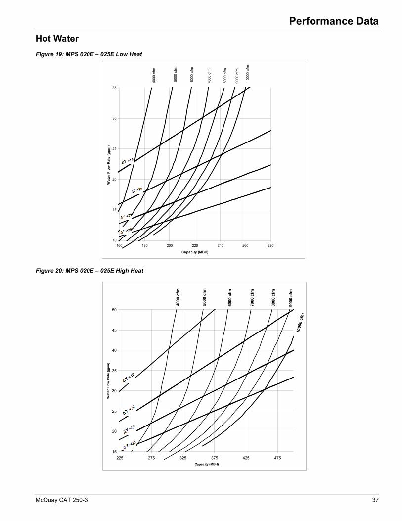
Performance Data
Hot Water
Figure 19: MPS 020E – 025E Low Heat
Figure 20: MPS 020E – 025E High Heat
4000
cfm
5000
cfm
6000
cfm
7000
cfm
8000
cfm
9000
cfm
1000
0 cf
m
10
15
20
25
30
35
160 180 200 220 240 260 280
Capacity (MBH)
Wat
er F
low
Rat
e (g
pm
)
4000
cfm
5000
cfm
6000
cfm
7000
cfm
8000
cfm
9000
cfm
1000
0 c
fm
15
20
25
30
35
40
45
50
225 275 325 375 425 475
Capacity (MBH)
Wa
ter
Flo
w R
ate
(g
pm
)
McQuay CAT 250-3 37
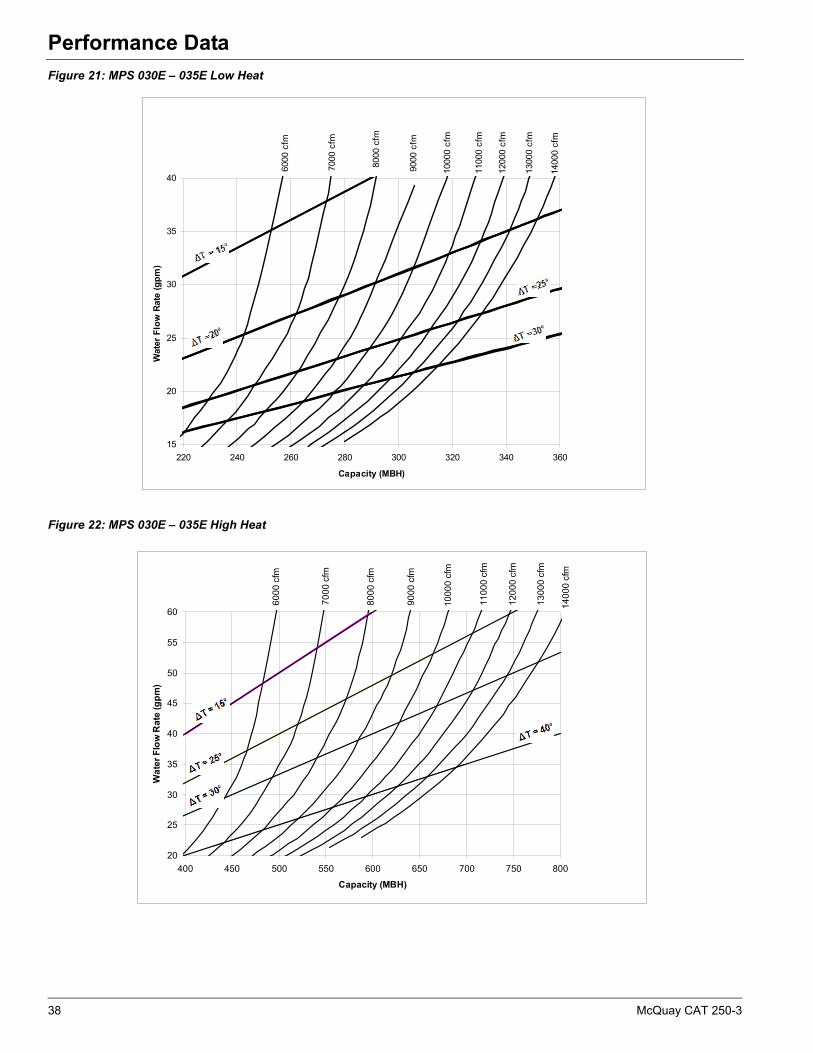
Performance Data
Figure 21: MPS 030E – 035E Low Heat
Figure 22: MPS 030E – 035E High Heat
6000
cfm
7000
cfm
8000
cfm
9000
cfm
1000
0 cf
m
1100
0 cf
m
1200
0 cf
m
1300
0 cf
m
1400
0 cf
m
15
20
25
30
35
40
220 240 260 280 300 320 340 360
Capacity (MBH)
Wat
er F
low
Rat
e (g
pm
)
60
00
cfm
70
00
cfm
80
00
cfm
90
00
cfm
10
00
0 c
fm
11
00
0 c
fm
12
00
0 c
fm
13
00
0 c
fm
14
00
0 c
fm
20
25
30
35
40
45
50
55
60
400 450 500 550 600 650 700 750 800
Capacity (MBH)
Wa
ter
Flo
w R
ate
(g
pm
)
38 McQuay CAT 250-3

Performance Data
Figure 23: MPS 040E – 050E Low Heat
Figure 24: MPS 040E – 050E High Heat
1100
0 cf
m
1200
0 cf
m
1300
0 cf
m
1400
0 cf
m
1500
0 cf
m
1600
0 cf
m
1700
0 cf
m
1800
0 cf
m
1900
0 cf
m20
000
cfm
20
25
30
35
40
45
50
55
60
65
350 375 400 425 450 475 500 525 550 575 600
Capacity (MBH)
Wat
er F
low
Rat
e (g
pm
)
11
00
0 c
fm
12
00
0 c
fm
13
00
0 c
fm
14
00
0 c
fm
15
00
0 c
fm
16
00
0 c
fm
17
00
0 c
fm
18
00
0 c
fm19
000
cfm
2000
0 cfm
40
60
80
100
120
700 750 800 850 900 950 1,000 1,050 1,100 1,150 1,200
Capacity (MBH)
Wa
ter
Flo
w R
ate
(g
pm
)
McQuay CAT 250-3 39
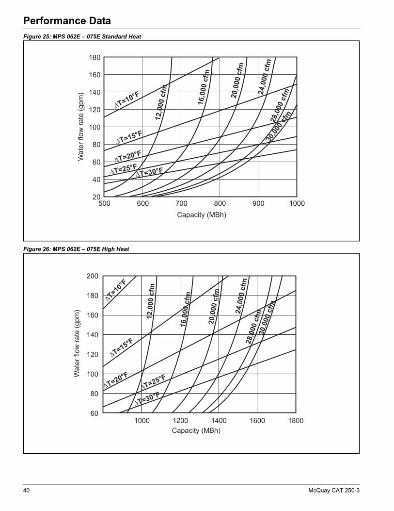
Performance Data
Figure 25: MPS 062E – 075E Standard Heat
Figure 26: MPS 062E – 075E High Heat
Capacity (MBh)
Wat
er fl
ow r
ate
(gpm
)
Capacity (MBh)
Wat
er fl
ow r
ate
(gpm
)
40 McQuay CAT 250-3

Performance Data
Fan Performance
Figure 27: MPS 020E – 025E, 22" Standard Fan, SWSI Airfoil Supply Fan
Figure 28: MPS 030E – 035E, 24" Standard Fan, SWSI Airfoil Supply Fan
0.0
1.0
2.0
3.0
4.0
5.0
6.0
0 1000 2000 3000 4000 5000 6000 7000 8000 9000 10000 11000 12000
Airflow (CFM)
Stat
ic P
ress
ure
(In H
2)
7.5BHP
10BHP
5BHP
3BHP
2BHP
15BHP
1.5BHP
2100
1900
1700
1500
1100
1300
900
2100
1900
1700
1500
1100
1300
900
BHP5BH
McQuay CAT 250-3 41

Performance Data
Figure 29: MPS 040E – 050E, 30" Standard Fan, SWSI Airfoil Supply Fan
Figure 30: MPS 062E – 075E 40-in. Standard Fan, SWSI Airfoil Supply Fan, Cooling Only or Hot Water
Note: Maximum allowable static pressure at fan bulkhead is 5.0 in. (i.e., supply duct ESP cannot exceed 5.0 in).
Airflow - cfm
0 2000 4000 6000 8000 10000120001400016000180002000022000240002600028000300003200034000
Sta
tic P
ress
ure
- in
. w.g
.
0.0
0.5
1.0
1.5
2.0
2.5
3.0
3.5
4.0
4.5
5.0
5.5
500
600
700
800
900
1000
1100
3.0
5.0
7.5
10.0
15.0
20.0
25.0
30.0
40.0 BHP
1200 RPM
1150
42 McQuay CAT 250-3

Performance Data
Figure 31: MPS 062E – 075E 44-in. Large Fan, SWSI Airfoil Supply Fan, Cooling Only or Hot Water
Note: Maximum allowable static pressure at fan bulkhead is 5.0 in. (i.e., supply duct ESP cannot exceed 5.0 in).
Figure 32: MPS 062E – 075E 30-in. Standard Fan, DWDI Airfoil Supply Fan
Note: Maximum allowable static pressure at fan bulkhead is 5.0 in. (i.e., supply duct ESP cannot exceed 5.0 in).
Airflow - cfm
0 2000 4000 6000 8000 10000 12000 14000 16000 18000 20000 22000 24000 26000 28000 30000 32000 34000
Sta
tic P
ress
ure
- in
. w.g
.
0.0
0.5
1.0
1.5
2.0
2.5
3.0
3.5
4.0
4.5
5.0
5.5
500
600
700
800
900 1000 RPM
3.0
5.0
7.5
10.0
15.0
20.0
25.0
30.0
40.0BHP
400
McQuay CAT 250-3 43

Performance Data
Figure 33: MPS 062E – 075E Large Fan, 33-in. Standard Fan, DWDI Airfoil Supply Fan, Gas or Electric Heat
Note: Maximum allowable static pressure at fan bulkhead is 5.0 in. (i.e., supply duct ESP cannot exceed 5.0 in).
44 McQuay CAT 250-3

Dimensional Data
Dimensional DataMPS 020E – 025E Unit Dimensions
Figure 34: MPS 020E – 025E Cooling/Electric Heating Unit
McQuay CAT 250-3 45
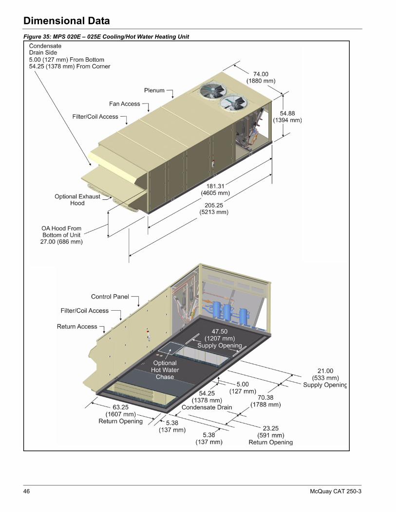
Dimensional Data
Figure 35: MPS 020E – 025E Cooling/Hot Water Heating Unit
46 McQuay CAT 250-3
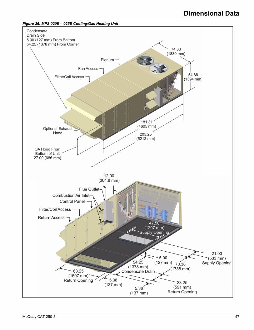
Dimensional Data
Figure 36: MPS 020E – 025E Cooling/Gas Heating Unit
McQuay CAT 250-3 47
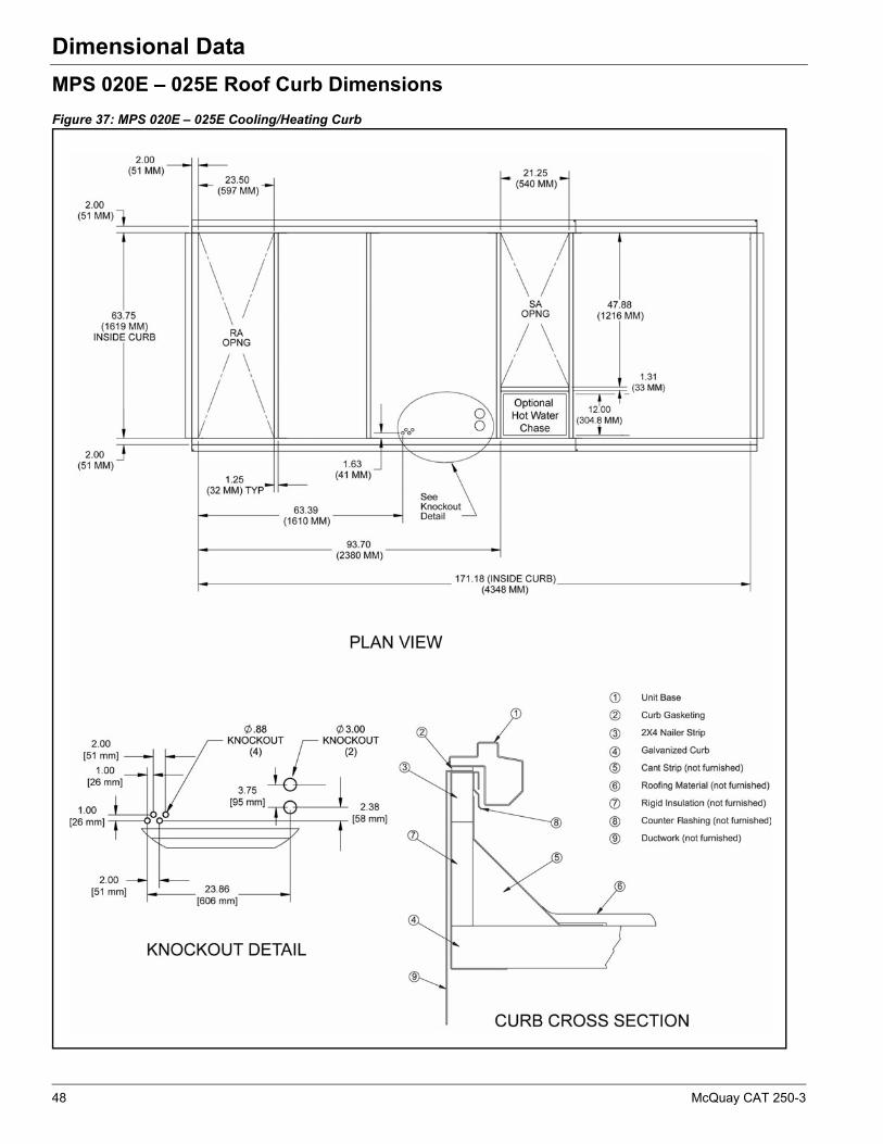
Dimensional Data
MPS 020E – 025E Roof Curb Dimensions
Figure 37: MPS 020E – 025E Cooling/Heating Curb
48 McQuay CAT 250-3
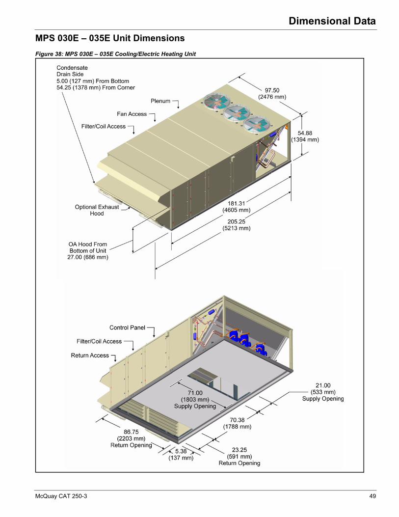
Dimensional Data
MPS 030E – 035E Unit Dimensions
Figure 38: MPS 030E – 035E Cooling/Electric Heating Unit
McQuay CAT 250-3 49
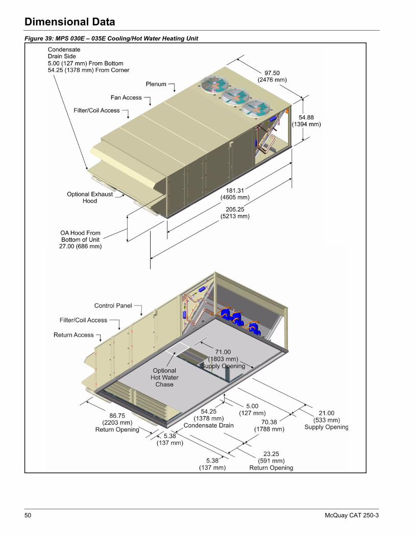
Dimensional Data
Figure 39: MPS 030E – 035E Cooling/Hot Water Heating Unit
50 McQuay CAT 250-3

Dimensional Data
Figure 40: MPS 030E – 035E Cooling/Gas Heating Unit
McQuay CAT 250-3 51
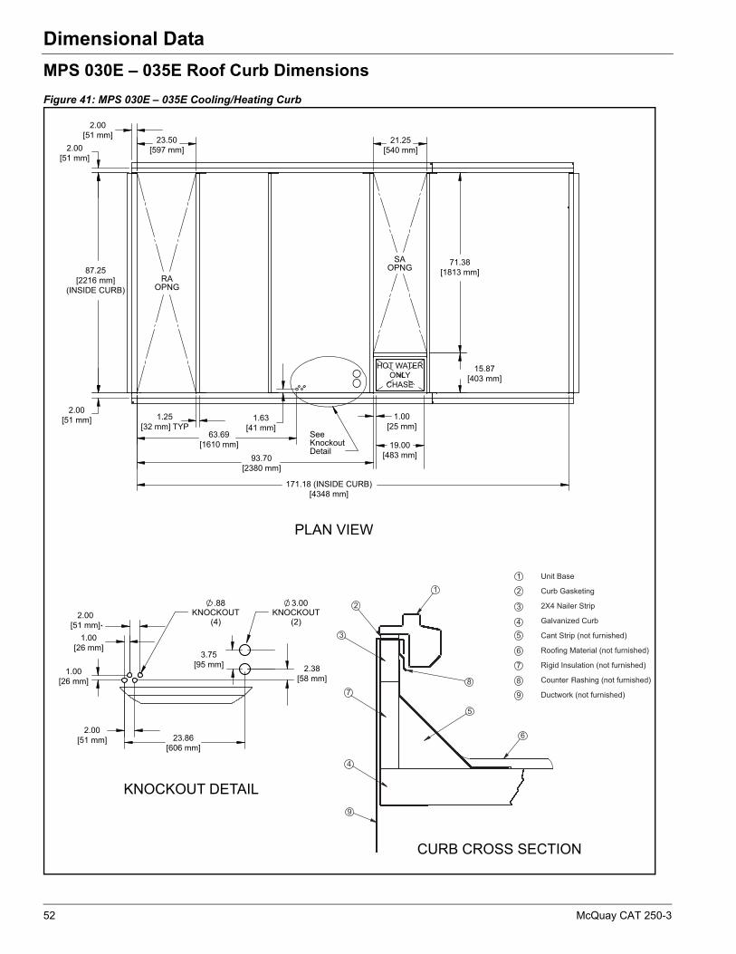
Dimensional Data
MPS 030E – 035E Roof Curb Dimensions
Figure 41: MPS 030E – 035E Cooling/Heating Curb
23.50[597 mm]
2.00[51 mm]
2.00[51 mm] 21.25
[540 mm]
71.38[1813 mm]
15.87[403 mm]
87.25[2216 mm]
(INSIDE CURB)
1.25[32 mm] TYP
1.63[41 mm]
93.70[2380 mm]
171.18 (INSIDE CURB)[4348 mm]
63.69[1610 mm]
2.00[51 mm]
2.00[51 mm]
1.00[26 mm]
1.00[26 mm]
2.00[51 mm]
2.38[58 mm]
3.75[95 mm]
PLAN VIEW
23.86[606 mm]
CURB CROSS SECTION
KNOCKOUT DETAIL
F
HOT WATERONLY
CHASE
1.00[25 mm]
19.00[483 mm]
52 McQuay CAT 250-3
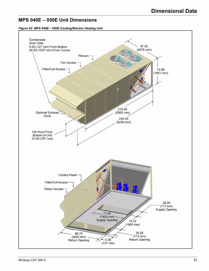
Dimensional Data
MPS 040E – 050E Unit Dimensions
Figure 42: MPS 040E – 050E Cooling/Electric Heating Unit
McQuay CAT 250-3 53

Dimensional Data
Figure 43: MPS 040E – 050E Cooling/Hot Water Heating Unit
54 McQuay CAT 250-3

Dimensional Data
Figure 44: MPS 040E – 050E Cooling/Gas Heating Unit
McQuay CAT 250-3 55

Dimensional Data
MPS 040E – 050E Roof Curb Dimensions
Figure 45: MPS 040E – 050E Cooling/Heating Curb
CURB CROSS SECTION
2.00[51 mm]
2.00[51 mm]
30.63[778 mm]
87.25[2216 mm]
(INSIDE CURB)
2.00[51 mm]
1.25 TYP[32 mm]
1.63[41 mm]
69.39[1763 mm]
105.45[2678 mm]
208.57 (INSIDE CURB)[5298 mm]
71.38[1813 mm]
15.87[403 mm]
28.25[718 mm]
2.00[51 mm]
2.00[51 mm]
1.00[25 mm]
2.28[58 mm]
3.75[95 mm]
28.92[735 mm]
PLAN VIEW
F
1.00[25 mm]
26.00[660 mm]
HOT WATERONLY
CHASE
56 McQuay CAT 250-3

Dimensional Data
MPS 062E Unit and Curb DimensionsNote: Exact length varies with options (refer to MPS 062E – 075E Additional Curb Dimensions‚ page 59).
Figure 46: Longest MPS 062E Cooling/Gas or Electric Heating Unit
Figure 47: Shortest MPS 062E Cooling Only Unit
McQuay CAT 250-3 57
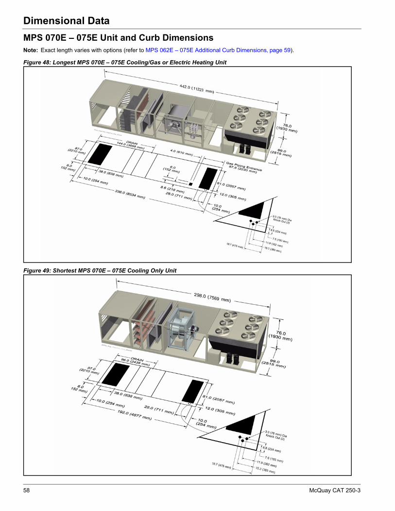
Dimensional Data
MPS 070E – 075E Unit and Curb DimensionsNote: Exact length varies with options (refer to MPS 062E – 075E Additional Curb Dimensions‚ page 59).
Figure 48: Longest MPS 070E – 075E Cooling/Gas or Electric Heating Unit
Figure 49: Shortest MPS 070E – 075E Cooling Only Unit
58 McQuay CAT 250-3
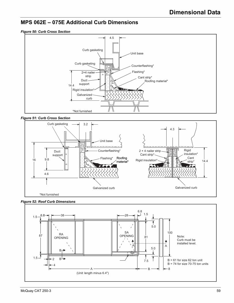
Dimensional Data
MPS 062E – 075E Additional Curb Dimensions
Figure 50: Curb Cross Section
Figure 51: Curb Cross Section
Figure 52: Roof Curb Dimensions
4.5
14.4
Curb gasketing
2×4 nailer strip
Ductsupport
Counterflashing*
Galvanizedcurb
Roofing material*Cant strip*
Flashing*
Unit base
*Not furnished
Curb gasketing
Rigid insulation*
*Not furnished
9.816
4.6
3.2
4.3
2 × 4 nailer stripCant strip*
14.4
Galvanized curb
Roofingmaterial*Roofingmaterial*
Flashing*
Unit base
Duct support
Curb gasketing
Galvanized curb
Counterflashing*
Rigid insulation*
Rigidinsulation*
Cantstrip*
87 RA OPENING
381.5
B
B2
4A B
81
28
100
8
7.5
5.0
5.0
AA
SA OPENING
(Unit length minus 6.4")
Note:Curb must beinstalled level.
1.5
1.56.86.86.8
B = 61 for size 62 ton unitB = 74 for size 70-75 ton units
McQuay CAT 250-3 59

Dimensional Data
MPS 062E – 075E Section Dimensions
Figure 53: MPS 062E – 075E Gas or Electric Heat Section Dimensions
Example: MPS 062E
For a custom certified drawing of your specific requirements, consult your local McQuay sales representative.
72
30” Dia
SupplyAir Fan
Mandatory
Air-cooledCondenser
106(Does not affect
curb length)
Air-cooledCondenser
83(Does not affect
curb length)
Air-cooledCondensing
Unit
48
DischargePlenum
DischargePlenum
Mandatory
48
(39.5 sq. ft.)
24
(47.1 sq. ft.)
DX CoilMandatory
48
30%Outside Air
Economizer
72
Outdoor/Return AirMandatory
Electric
Gas
48
48
HeatMandatory
Angular
24
Cartridge(40 sq. ft.)
24
Cartridge(48 sq. ft.)
FilterMandatory
Econ w/ Prop. Exh.Fans, Bottom or
Back Ret.
72
Position A Position B Position D Position F Position G Position K Position M
Size 62
Size 70-75
N/A on Size 70-75
96
33” Dia
Section description Length (in.)
Bottom return economizer with exhaust air fan = 72
Angular filters = 24
Standard size cooling coil = 24
Supply fan = 72
Gas heat = 48
Discharge plenum = 48
Air cooled condensing unit = 83
Total air handler length = 288
Total unit length (including condensing unit) = 371
60 McQuay CAT 250-3

Dimensional Data
Figure 54: MPS 062E – 075E Cooling Only or Hot Water Section Dimensions
30% OA
48 in.
Economizer
72 in.
TA/30
24 in.
65/9540 ft2
24 in.
65/9548 ft2
48 in.
40.1 ft2
24 in.
47.4 ft2
48 in.
S&HW
48 in.
44 in. Dia
72 in. 83 in.
106 in.
Exhaust/ReturnAir Filter DX Coil Optional
HeatSupply Air
FanAir-Cooled
Condensing Unit
Econ w/ Prop. Exh.Fans, Bottom orBack Ret. Fans
72
Size 62
Size 70-75
N/A on Size 70-75
(Does not affectcurb length)
(Does not affectcurb length)
McQuay CAT 250-3 61

Dimensional Data
MPS 062E – 075E Knockout Dimensions
Figure 55: Main Control Panel/Discharge Plenum Knockouts
Figure 56: Main Control Panel/Discharge Plenum Knockout Detail
Figure 57: Gas Heat/Heat Section
17.7
3.0 dia. K.O.(qty = 3)
0.9 dia. K.O.(qty = 4)
11.9
12.9
15.3
6.6
18.7
22.3
24.3
7.6
8.8
Reference fromleaving air end of section
5.112.1
3.4
4.84.6
2.0
9.7
2.1 3.1 4.3
0.9 diameter K.O. (quantity = 4)
3.0 diameter K.O. (quantity = 3)
Recommended p iping entrance (through the curb)
BA
C
D
A B C D
8.6 6.0 4.2 4.0
62 McQuay CAT 250-3
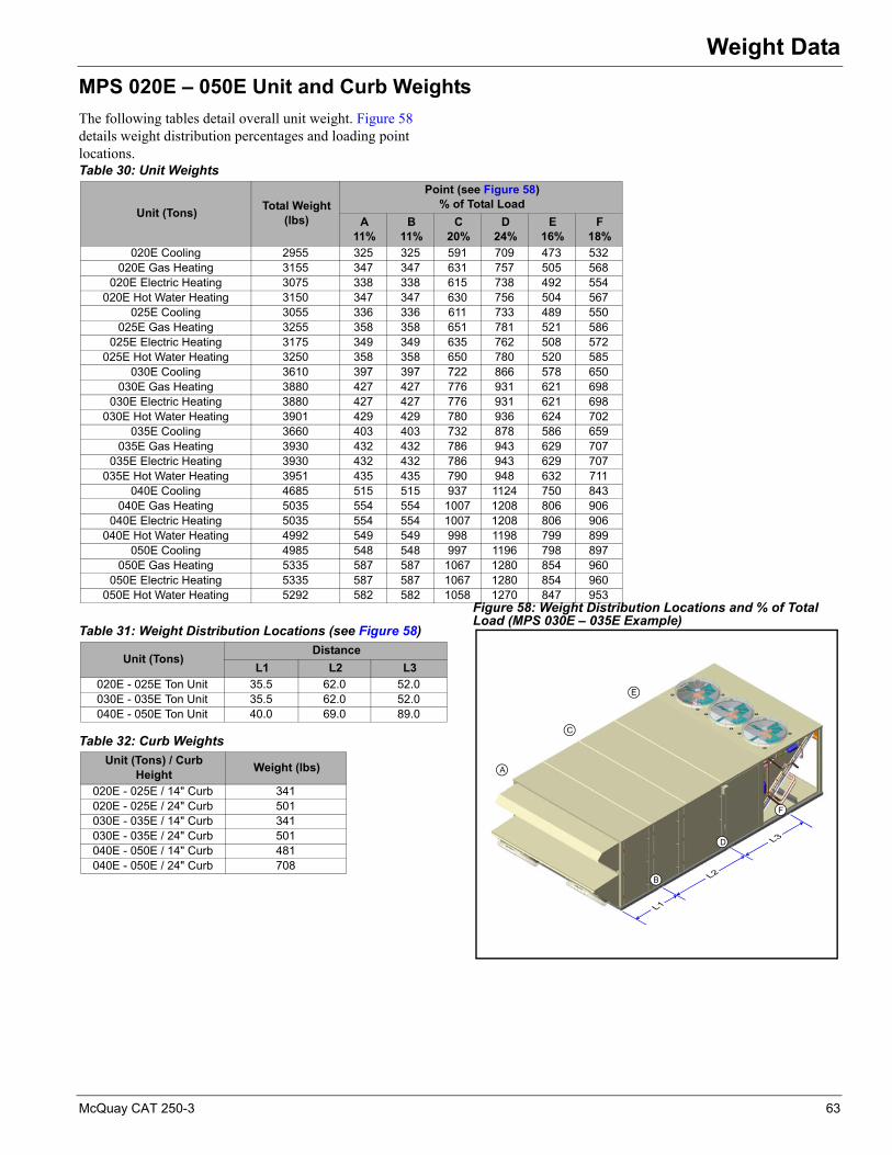
Weight Data
Weight DataMPS 020E – 050E Unit and Curb Weights
The following tables detail overall unit weight. Figure 58 details weight distribution percentages and loading point locations.
Figure 58: Weight Distribution Locations and % of Total Load (MPS 030E – 035E Example)
Table 30: Unit Weights
Unit (Tons)Total Weight
(lbs)
Point (see Figure 58)% of Total Load
A11%
B11%
C20%
D24%
E16%
F18%
020E Cooling 2955 325 325 591 709 473 532020E Gas Heating 3155 347 347 631 757 505 568
020E Electric Heating 3075 338 338 615 738 492 554020E Hot Water Heating 3150 347 347 630 756 504 567
025E Cooling 3055 336 336 611 733 489 550025E Gas Heating 3255 358 358 651 781 521 586
025E Electric Heating 3175 349 349 635 762 508 572025E Hot Water Heating 3250 358 358 650 780 520 585
030E Cooling 3610 397 397 722 866 578 650030E Gas Heating 3880 427 427 776 931 621 698
030E Electric Heating 3880 427 427 776 931 621 698030E Hot Water Heating 3901 429 429 780 936 624 702
035E Cooling 3660 403 403 732 878 586 659035E Gas Heating 3930 432 432 786 943 629 707
035E Electric Heating 3930 432 432 786 943 629 707035E Hot Water Heating 3951 435 435 790 948 632 711
040E Cooling 4685 515 515 937 1124 750 843040E Gas Heating 5035 554 554 1007 1208 806 906
040E Electric Heating 5035 554 554 1007 1208 806 906040E Hot Water Heating 4992 549 549 998 1198 799 899
050E Cooling 4985 548 548 997 1196 798 897050E Gas Heating 5335 587 587 1067 1280 854 960
050E Electric Heating 5335 587 587 1067 1280 854 960050E Hot Water Heating 5292 582 582 1058 1270 847 953
Table 31: Weight Distribution Locations (see Figure 58)
Unit (Tons)Distance
L1 L2 L3
020E - 025E Ton Unit 35.5 62.0 52.0030E - 035E Ton Unit 35.5 62.0 52.0040E - 050E Ton Unit 40.0 69.0 89.0
Table 32: Curb Weights
Unit (Tons) / Curb Height
Weight (lbs)
020E - 025E / 14" Curb 341020E - 025E / 24" Curb 501030E - 035E / 14" Curb 341030E - 035E / 24" Curb 501040E - 050E / 14" Curb 481040E - 050E / 24" Curb 708
McQuay CAT 250-3 63

Weight Data
MPS 062E – 075E Unit Weights
The following table details unit weights for the MPS 062E - 075E ton units. \
Note: Basic unt consists of return air plenum, angular filter section, supply air fan section without fan or motor, cooling section without coil, and condensing unit.
Fan Motor Weights
Roof Curb Weights
Calculate the weight of the unit curb using the following equations:
Note: Curb length does not include condenser length.
Additional Weights1 For bottom return opening, add 91 lbs.
2 For bottom discharge opening, add 78 lbs.
3 Cross supports:– For curb length greater than 288 in., add 30 lbs.
Example: MPS 070E with Gas Heat
Note: For structural purposes, consider roof curb weight.
Table 33: MPS 062E to 075E (lbs.)
Components 062E 070E 075E
Unit configurationMPS, basic unit* 5460 5720 5895Outdoor/return air optionsReturn air plenum Included in basic unit0–30% O.A. hood 222 222 222 0–100% economizer 1065 1065 1065 Filter options30% pleated 4 4 4 65% cartridge—standard flow 57 57 57 —Medium flow 538 538 538 95% cartridge—standard flow 67 67 67 —Medium flow 550 550 550 Supply air fan assemblyCooling only or hot water 1217 1217 1217Gas or electric heat 965 965 965Evaporator coils—aluminum fins, standard airflow face area5-row, 10 fpi 559 N/A N/AEvaporator coils—aluminum fins, high airflow face area5-row, 10 fpi 1224 1224 1224 Hot water coil1-row 373 373 3732-row 449 449 449Electric Heat100 kW low capacity electric heat 1555 1555 1555160 kW medium capacity electric heat 1575 1575 1575200 kW high capacity electric heat 1600 1600 1600Gas Heat400 MBh low fire furnace 1630 1630 1630640 MBh medium fire furnace 1690 1690 1690790 MBh high fire furnace 1780 1780 1780Exhaust air fan assembly1 fan, bottom or back return 525 525 5252 fans, bottom or back return 785 785 785Accessory itemsVariable frequency drive—SAF 150 150 150Insulation liners2’’, 1.5 lbs., with solid liners:weight per foot of unit length
25 25 25
Table 34: Supply, Exhaust and Return Fan Motors
Motor hpWeight (lbs)
Totally enclosed
5 85
7.5 140
10 170
15 235
20 300
25 330
30 390
40 510
Weight formulaBase curb wt. (lb.) = 170 + 0.74 [170 + 2 × curb length (in.)] + additional weight (steps 1-3 below) as required
Component Lbs.Basic unit 5,720
Economizer 1,06530% efficiency filters 4Supply fan 965DX coil— high airflow 1,224SAF motor—40 hp 510
Liners 650= 10,138 lbs
Liner calculationsSection Economizer 6
Filter 2Supply fan 6Heat 4DX coil 4Discharge plenum 4Total length of air handler (feet)
26
× 25 lbs. per ft. = 650 lbs.
64 McQuay CAT 250-3

Electrical Data
Electrical DataPower WiringTable 35: Recommended Supply Data
Ampacity No. of Power Wires per Phase Wire GaugeInsulation
Rating(0°C)
30 1 10 75 40 1 8 7555 1 6 7570 1 4 7585 1 3 7595 1 2 75
130 1 1 75150 1 1/0 75175 1 2/0 75200 1 3/0 75230 1 4/0 75255 1 250 75
AmpacityNo. of Power Wires per Phase Wire Gauge
Insulation Rating(0°C)
MPS 020-025 MPS 030-050 MPS 062-075 MPS 020-025 MPS 030-050 MPS 062-075 MPS 020-075300 2 2 1 1/0 1/0 300 75350 2 2 1 2/0 2/0 400 75400 2 2 2 3/0 3/0 3/0 75460 2 2 2 4/0 4/0 4/0 75510 2 2 2 250 250 250 75600 3 3 2 3/0 3/0 350 75690 3 3 2 4/0 4/0 400 75765 3 3 2 250 250 500 75
Table 36: SAF Data and MPS 062E-075E EAF Data
HP Voltage Amps
5 208 15.05 230 13.25 460 6.65 575 5.2
7.5 208 23.07.5 230 19.47.5 460 9.77.5 575 8.010 208 26.010 230 25.010 460 13.010 575 10.015 208 37.415 230 35.415 460 17.715 575 14.120 208 49.020 230 47.020 460 24.020 575 19.025 208 63.025 230 60.025 460 31.025 575 24.030 208 74.030 230 70.030 460 35.030 575 28.040 208 11.040 230 96.040 460 48.040 575 38.0
McQuay CAT 250-3 65

Electrical Data
Table 37: Condenser Fan Quantity Data
Size Condenser Fan Quantity
20-25 230-35 340-50 462-70 6
75 8
Table 38: Condenser Fan Motor Data
VoltageFull Load Amps Per Condenser
Fan Motor
208/230 4460 2575 1.7
Table 39: MPS 020E – 050E Exhaust Fan Data (MPS 062E – 075E use 1 or 2 5hp Motors - see Figure 36)
Size Voltage HP Amps Qty. Total (Amps)
20
208 1 4.2 2 8.4230 1 4.0 2 8.0460 1 2.0 2 4.0575 1 1.7 2 3.4
25
208 1 4.2 2 8.4230 1 4.0 2 8.0460 1 2.0 2 4.0575 1 1.7 2 3.4
30
208 1 4.2 2 8.4230 1 4.0 2 8.0460 1 2.0 2 4.0575 1 1.7 2 3.4
35
208 1 4.2 2 8.4230 1 4.0 2 8.0460 1 2.0 2 4.0575 1 1.7 2 3.4
40
208 1 4.2 3 12.6230 1 4.0 3 12.0460 1 2.0 3 6.0575 1 1.7 3 5.1
50
208 1 4.2 3 12.6230 1 4.0 3 12.0460 1 2.0 3 6.0575 1 1.7 3 5.1
Table 40: Rated Load Amps Per Compressor — MPS 020E – 050E
Size Voltage Comp #1 Comp #2 Comp #3 Comp #4
20208/230 20.2 22.3 20.2 -
460 9.2 10.2 9.2 -575 8.5 8.9 8.5 -
25208/230 20.2 35.4 20.2 -
460 9.2 17.4 9.2 -575 8.5 13.9 8.5 -
30208/230 36 27 27 -
460 16.5 14 14 -575 14 11 11 -
35208/230 36 36 27 -
460 16.5 16.5 14 -575 14 14 11 -
40208/230 36 36 36 -
460 16.5 16.5 16.5 -575 14 14 14 -
50208/230 36 36 36 36
460 16.5 16.5 16.5 16.5575 14 14 14 14
66 McQuay CAT 250-3

Electrical Data
Supply Power Wiring Data
Electric Heater Data
The following formulas can be used to calculate Minimum circuit Ampacity (MCA) and Maximum Rated Overcurrent Protection Device (MROPD).
Cooling Only/Cooling with Gas Heat/Hot Water Heat
MCA = 1.25 x current draw of largest motor/compressor + current draw of the rest of the motors/compressors + 1 (controls).
MROPD = 2.25 x current draw of largest motor/compressor + current draw of the rest of motors/compressors + 1 (controls).
Elect. Heat (sizes 20-70 and size 75 with 160-200 kW)
MCA = 1.25 x (supply fan motor amps + exhaust fan motor amps + transformer) + electric heat load.
MROPD = 2.25 (largest fan motor) + electric heat load + remaining fan motor + transformer.
Electric Heat (Size 75, 100 kW)
MCA = 1.25 x current draw of largest motor/compressor + current draw of the rest of the motors/compressors + 1 (controls).
MROPD = 2.25 x current draw of largest motor/compressor + current draw of the rest of motors/compressors + 1 (controls).
Table 41: Rated Load Amps—MPS 062E – 075E
Model VoltageCircuit 1 Circuit 2
RLA / comp
Comp QtyRLA / comp
Comp Qty
062
208-60-3 56.7 2 56.7 2
230-60-3 51.3 2 51.3 2
460-60-3 23.1 2 23.1 2
575-60-3 19.9 2 19.9 2
070
208-60-3 36.8 3 36.8 3
230-60-3 33.3 3 33.3 3
460-60-3 17.9 3 17.9 3
575-60-3 12.8 3 12.8 3
75
208-60-3 53.2 3 53.2 3
230-60-3 48.1 3 48.1 3
460-60-3 18.6 3 18.6 3
575-60-3 14.7 3 14.7 3
Table 42: MPS 020E – 050E Electric Heater DatakW Voltage Amps54 208 15054 230 13054 460 6554 575 5272 208 20072 230 173
72 460 8672 575 7090 208 25090 230 21790 460 10890 575 87
108 460 130108 575 104
Table 42: MPS 020E – 050E Electric Heater DatakW Voltage Amps
Table 43: MPS 062E – 075E Electric Heat Data
Model208/60/3 240/60/3 480/60/3 600/60/3
kW FLA Stages kW FLA Stages kW FLA Stages kW FLA Stages
100 74.7 207.4 4 99.5 239.4 4 99.5 119.7 4 99.5 95.7 4160 119.7 332.0 4 159.2 383.0 4 159.2 191.5 4 159.2 153.2 4200 - - - - - - 199.0 239.4 4 199.0 191.5 4
McQuay CAT 250-3 67
Engineering Guide Specification
Engineering Guide SpecificationPart 1: General
1.01 Section Includes:A Packaged rooftop air conditioners.
1.02 ReferencesA AFBMA 9-Load Ratings and Fatigue Life for Ball
Bearings.
B AMCA 99-Standards Handbook.
C AMCA 210-Laboratory Methods of Testing Fans for Rating Purposes.
D AMCA 300-Test Code for Sound Rating Air Moving Devices.
E AMCA 500-Test Methods for Louver, Dampers, and Shutters.
F ARI 410-Forced-Circulation Air-Cooling and Air-Heating Coils.
G ARI 430-Central-Station Air-Handling Units.
H ARI 435-Application of Central-Station Air-Handling Units.
I IBC 2000 - International Building Code.
J NEMA MG1-Motors and Generators.
K National Electrical Code.
L NFPA 70-National Fire Protection Agency.
M SMACNA-HVAC Duct Construction Standards-Metal and Flexible.
N UL 900-Test Performance of Air Filter Units.
1.03 SUBMITTALS
A Shop Drawings: Indicate assembly, unit dimensions, weight loading, required clearances, construction details, field connection details, electrical characteristics and connection requirements.
B Product Data:
1 Provide literature that indicates dimensions, weights, capacities, ratings, fan performance, and electrical characteristics and connection requirements.
2 Provide computer generated fan curves with specified operating point clearly plotted.
3 Manufacturer's installation instructions.
1.04 Operation And Maintainence Data
A Maintenance Data: Provide instructions for installation, maintenance and service.
1.05 Qualifications
A Manufacturer: Company specializing in manufacturing the Products specified in this section with minimum five years documented experience, who issues complete catalog data on total product.
B Startup must be done by trained personnel experienced with rooftop equipment.
C Do not operate units for any purpose, temporary or permanent, until ductwork is clean, filters and remote controls are in place, bearings lubricated, and manufacturers' installation instructions have been followed.
1.06 Delivery, Storage, And Handling
A Deliver, store, protect and handle products to site.
B Accept products on site and inspect for damage.
C Store in clean dry place and protect from weather and construction traffic. Handle carefully to avoid damage to components, enclosures, and finish.
Part 2: Products
2.01 ManufacturersA Basis of Design: McQuay International
1 McQuay.
2 Trane.
3 Carrier.
4 York.
5 AAON.
2.02 General DescriptionA Furnish as shown on plans, McQuay Maverick Singlezone
Heating and Cooling Unit(s) model MPS. Unit performance and electrical characteristics shall be per the job schedule.
B Configuration: Fabricate as detailed on prints and drawings:
1 Return plenum/economizer section.
2 Filter section.
3 Cooling coil section.
4 Supply fan section.
5 Gas heating section.
6 Electric heating section.
7 Hot water heating section.
8 Condensing unit section.
C The complete unit shall be cETLus/MEA listed.
D The burner and gas train for the unit furnace shall be cETLus approved.
E Each unit shall be specifically designed for outdoor rooftop application and include a weatherproof cabinet. Each unit shall be completely factory assembled and shipped in one piece. MPS packaged units shall be shipped fully charged with Refrigerant 410A and oil.
68 McQuay CAT 250-3
Engineering Guide Specification
F The unit shall undergo a complete factory run test prior to shipment. The factory test shall include final balancing of the supply fan assemblies, a refrigeration circuit run test, a unit control system operations checkout, a unit refrigerant leak test and a final unit inspection.
G All units shall have decals and tags to indicate caution areas and aid unit service. Unit nameplates shall be fixed to the main control panel door. Electrical wiring diagrams shall be attached to the control panels. Installation, operating and maintenance bulletins and start-up forms shall be supplied with each unit.
H Performance: All scheduled capacities and face areas are minimum accepted values. All scheduled amps, kW, and HP are maximum accepted values that allow scheduled capacity to be met.
I Warranty: The manufacturer shall provide 12-month parts only warranty. Defective parts will be repaired or replaced during the warranty period at no charge. The warranty period shall commence at startup or six months after shipment, whichever occurs first.
2.03 Cabinet, Casing, And FrameA Panel construction shall be double-wall construction for all
panels. All floor panels shall have a solid galvanized steel inner liner on the air stream side of the unit to protect insulation during service and maintenance. Insulation shall be a minimum of 1" thick with an R-value of [4.0 on MPS 020-050 ton units] [6.5 on MPS 062-075 ton units], and shall be neoprene coated glass fiber. Panel design shall include no exposed insulation edges. Unit cabinet shall be designed to operate at total static pressures up to [5.0 on sizes 20-50] [6.5 on sizes 62-75] inches w.g.
B Double wall construction shall be the minimum design in all sections down stream of the cooling coil section. This shall include the fan, gas heat, and discharge plenum sections as a minimum.
C Exterior surfaces shall be constructed of pre-painted galvanized steel for aesthetics and long term durability. Paint finish to include a base primer with a high quality, polyester resin topcoat of a neutral beige color. Finished panel surfaces to withstand a minimum 750-hour salt spray test in accordance with ASTM B117 standard for salt spray resistance.
D Service doors shall be provided on both sides of the fan section, coil section, economizer section, control panel, and the filter section in order to provide user access to unit components. All service access doors shall be mounted on multiple, stainless steel hinges and shall be secured by a latch system. Removable service panels secured by multiple mechanical fasteners are not acceptable.
E The unit base shall overhang the roof curb for positive water runoff and shall seat on the roof curb gasket to provide a positive, weathertight seal. Lifting brackets shall
be provided on the unit base to accept cable or chain hooks for rigging the equipment.
2.04 Supply Fan
A Supply fan shall be a [SWSI airfoil centrifugal fan] [DWDI on sizes 62-75 with gas or electric heat]. The fan blade design shall be a double blade with the airfoil geometry, a backward inclined blade fan wheel design will not be acceptable. The fan wheel shall be Class II construction with aluminum fan blades welded to the back plate and end rim. The supply fan shall be mounted using solid-steel shafts and wheel hubs with mating keyways.
B The fan assembly shall have fixed pitched drives with a minimum of two belts. The drives shall be selected with a minimum diameter of 4 inches and a 1.2 service factor. The belts shall be of the grip-notch design.
C All fan assemblies shall be statically and dynamically balanced at the factory, including a final trim balance, prior to shipment. All fan assemblies shall employ solid steel fan shafts. Heavy-duty concentric locking pillow block type, self-aligning, grease lubricated ball bearings shall be used. Bearings shall be sized to provide a L-50 life at 250,000 hours. The entire fan assembly shall be isolated from the fan bulkhead and mounted on spring isolators [1" on sizes 20-50] [2" on sizes 62-75].
D Fan motors shall be heavy-duty 1800 rpm open drip-proof (ODP) type with grease lubricated ball bearings. Motors shall be premium efficiency. Motors shall be mounted on an adjustable base that provides for proper alignment and belt tension adjustment. Motors shall be suitable for use with a variable frequency drive.
E The supply fan shall be capable of airflow modulation from 30% to 100% of the scheduled designed airflow. The fan shall not operate in a state of surge at any point within the modulation range.
2.05 Exhaust FanA Exhaust fans shall be provided. Blades shall be constructed
with fabricated steel and shall be securely attached to fan shafts. All exhaust fan assemblies shall be statically and dynamically balanced. Motors shall be permanently lubricated, heavy-duty type, carefully matched to the fan load. Ground and polished steel fan shafts shall be mounted in permanently lubricated and sealed ball bearings. Bearings shall be selected for a minimum (L10) life in excess of 100,000 hours at maximum cataloged operating speeds.
B The unit DDC controller shall provide building static pressure control. A factory mounted exhaust fan variable frequency drive shall provide proportional control of the exhaust fans from 25% to 80% of the supply air fan designed airflow. The field shall mount the required sensing tubing from the building to the factory mounted building static pressure sensor.
McQuay CAT 250-3 69

Engineering Guide Specification
2.06 Variable Air Volume ControlA An electronic variable frequency drive shall be provided
for the supply air fan. Each drive shall be factory installed in a conditioned cabinet. Drives shall meet UL Standard 95-5V. The completed unit assembly shall be listed by a recognized safety agency, such as ETL. Drives are to be accessible through a hinged door assembly. Mounting arrangements that expose drives to high temperature unfiltered ambient air are not acceptable.
B The unit manufacturer shall install all power and control wiring.
C The supply air fan drive output shall be controlled by the factory installed main unit control system and drive status and operating speed shall be monitored and displayed at the main unit control panel.
2.07 ElectricalA Unit wiring shall comply with NEC requirements and with
all applicable UL standards. All electrical components shall be UL recognized where applicable. All wiring and electrical components provided with the unit shall be number and color-coded and labeled according to the electrical diagram provided for easy identification. The unit shall be provided with a factory wired weatherproof control panel. Unit shall have a single point power terminal block for main power connection. A terminal board shall be provided for low voltage control wiring. Branch short circuit protection, 115-volt control circuit transformer and fuse, system switches, and a high temperature sensor shall also be provided with the unit. Each compressor and condenser fan motor shall be furnished with contactors and inherent thermal overload protection. Supply fan motors shall have contactors and external overload protection. Knockouts shall be provided in the bottom of the main control panels for field wiring entrance.
B A single non-fused disconnect switch shall be provided for disconnecting electrical power at the unit. Disconnect switches shall be mounted internally to the control panel and operated by an externally mounted handle.
C A GFI receptacle shall be unit mounted. The receptacle will require a field power connection independent from the unit's main power block and/or disconnect.
D A GFI receptacle shall be unit mounted. The receptacle shall be powered by a factory installed and wired 120 V, 20 amp power supply. The power supply shall be wired to the line side of the unit's main disconnect, so the receptacle is powered when the main unit disconnect is off. This option shall include a GFI receptacle, transformer, and a branch circuit disconnect. The electrical circuit shall be complete with primary and secondary overload protection.
2.08 Cooling SectionA The cooling coil section shall be installed in a draw through
configuration, upstream of the supply air fan. The coil
section shall be complete with a factory piped cooling coil and an ASHRAE 62.1 compliant double sloped drain pan.
B Direct expansion (DX) cooling coils shall be fabricated of seamless high efficiency copper tubing that is mechanically expanded into high efficiency aluminum plate fins. Coils shall be a multi-row, staggered tube design with a minimum of 4 rows and a maximum of 12 fins per inch. All units shall have two independent refrigerant circuits and shall use an interlaced coil circuiting that keeps the full coil face active at all load conditions. All coils shall be factory leak tested with high pressure air under water.
C A stainless steel or polymer positively sloped drain pan shall be provided with the cooling coil. The drain pan shall extend beyond the leaving side of the coil. The drain pan shall have a minimum slope of 1/8" per foot to provide positive draining. The slope of the drain pan shall be in two directions and comply with ASHRAE Standard 62.1 The drain pan shall be connected to a threaded drain connection extending through the unit base. [Drain pan shall be removable from the side of the unit without the removal of the cooling coil on sizes 20-50].
2.09 Staged Gas Heating Section
A The rooftop unit shall include a natural gas heating section. The gas furnace design shall be one or more natural gas fired heating modules factory installed downstream of the supply air fan in the heat section. Each module shall have two stages of heating control. The heating module shall be a tubular design with in-shot gas burners. The heat exchanger tubes shall be constructed of 20 ga, G160, aluminized steel. The module shall have an induced draft fan that will maintain a negative pressure in the heat exchanger tubes for the removal of the flue gases.
B Each burner module shall have two flame roll-out safety protection switches and a high temperature limit switch that will shut the gas valve off upon detection of improper burner manifold operation. The induced draft fan shall have an airflow safety switch that will prevent the heating module from turning on in the event of no airflow in the flue chamber.
C The factory-installed DDC unit control system shall control the gas heat module. Field installed heating modules shall require a field ETL certification. The manufacturer's rooftop unit ETL certification shall cover the complete unit including the gas heating modules.
D The heating modules shall have a field installed kit for conversion of the unit to LP gas.
2.10 Modulating Gas Heating SectionA [20-50 Low Capacity] The rooftop unit shall include a
natural gas heating section. The gas furnace design shall have a natural gas fired heating module factory installed downstream of the supply air fan in the heat section. The module shall be complete with furnace controller and control valve capable of modulating operation from 100%
70 McQuay CAT 250-3

Engineering Guide Specification
down to 28% of full fire capacity. The heating module shall be a tubular design with in-shot gas burners. The heat exchanger tubes shall be constructed of stainless steel. The module shall have an induced draft fan that will maintain a negative pressure in the heat exchanger tubes for the removal of the flue gases.
B [20-50 High Capacity] The rooftop unit shall include a natural gas heating section. The section design shall be two natural gas fired heating modules factory installed downstream of the supply air fan in the heat section. One module shall have two stages of capacity control. The other module shall be complete with furnace controller and control valve capable of modulating operation from 100% down to 14% of the unit's total full fire capacity. The heating modules shall be a tubular design with in-shot gas burners. The heat exchanger tubes shall be constructed of stainless steel. The module shall have an induced draft fan that will maintain a negative pressure in the heat exchanger tubes for the removal of the flue gases.
C Each 20-50 size burner module shall have two flame roll-out safety protection switches and a high temperature limit switch that will shut the gas valve off upon detection of improper burner manifold operation. The induced draft fan shall have an airflow safety switch that will prevent the heating module from turning on in the event of no airflow in the flue chamber.
D Each 62-75 natural gas fired furnace shall be installed in the unit heat section. The heat exchanger shall include a type 321 stainless steel cylindrical primary combustion chamber, a type 321 stainless steel header, type 321 stainless steel secondary tubes and type 321 stainless steel turbulators. The heat exchanger shall have a condensate drain. Clean out of the primary heat exchanger and secondary tubes shall be accomplished without removing casing panels or passing soot through the supply air passages. The furnace section shall be positioned downstream of the supply air fan to maintain positive pressure around the heat exchanger.
The furnace will be supplied with a modulating forced draft burner. The burner shall be controlled for low fire start. The burner shall be capable of continuous modulation between 33% and100% of rated capacity and shall operate efficiently at all firing rates.
The burner shall be specifically designed to burn natural gas and shall include a microprocessor based flame safeguard control, combustion air proving switch, pre-purge timer and spark ignition. The gas train shall include redundant gas valves, maximum 0.5psi pressure regulator, shutoff cock, pilot gas valve, pilot pressure regulator, and pilot cock. The burner shall be rated for operation and full modulation capability at inlet gas pressures down to 7.5 W.C.
E The factory-installed DDC unit control system shall control the gas heat module. Field installed heating modules shall require a field ETL certification. The manufacturer's
rooftop unit ETL certification shall cover the complete unit including the gas heating modules.
2.10 Electric Heating SectionA Heating coils shall be constructed of a low watt density,
high nickel chromium alloy resistance wire, mechanically stacked and heli-arc welded to corrosion resistant terminals. A corrosion resistant heavy gauge rack shall support the elements. Safety controls shall include automatic reset high limit control with manual reset backup line break protection. Heating element branch circuits shall be fused to maximum of 48 Amps per NEC requirements.
B The electric heat section shall be positioned downstream of the supply air fan.
C Proof of airflow must be established any time the electric heat element is energized.
D The electric heat elements shall be controlled by the factory installed main unit DDC control system. The control system will have four distinct stages of heating on any unit over 25 tons. Each stage control contactor shall be a three pole contactor. When the stage control contactor is not energized, it must break all three phases of power input to the electric heater.
E The electrical power supply for the electric heater shall be from the rooftop unit control panel. Unit shall have a single point power supply connection. Independent supply power connection to the electric heater will not be accepted.
F All disconnects must be three pole to remove power from all incoming legs.
2.11 Hot Water Heating SectionA A [1] [2] row hot water heating coil shall be factory
installed in the unit heat section. Coils shall be fabricated of seamless 5/8" diameter copper tubing that is mechanically expanded into high efficiency rippled and corrugated aluminum plate fins. All coil vents and drains shall be factory installed. The hot water heat section shall be installed downstream of the supply air fan. A factory-tested diffuser shall be used in order to provide air distribution across the coil.
B Hot water coil shall be fully cased to allow for easy replacement.
C Factory shall provide a field piping vestibule. The control valve shall be field supplied and installed in the unit heater vestibule. The control valve shall be capable of receiving a 2 - 10 VDC signal. Connection holes through the base of the unit in the field piping vestibule shall be cut and sealed by the field.
D All coil connections shall be copper, steel connections shall not be allowed in order to prevent dielectrics and corrosion.
E Fluid pressure drop shall conform to the mechanical schedule.
McQuay CAT 250-3 71

Engineering Guide Specification
F Freeze protection by the DDC controller and use the discharge air sensor. DDC controller shall be capable of sending an alarm signal.
G Coil shall be factory leak tested with high pressure air under water.
2.12 Filters
Draw-Through Filters
A Sizes 20-50 shall be provided with a draw-through filter section. The filter rack shall be designed to accept a 2" prefilter and a 4" final filter. The unit design shall have a hinged access door for the filter section. The manufacturer shall ship the rooftop unit with 2" construction filters. The contractor shall furnish and install, at building occupancy, the final set of filters per the contract documents.
B Size 62-75 ton units shall be provided with a draw-through filter section. The filter section shall be supplied complete with the filter rack as an integral part of the unit. The draw-through filter section shall be provided with [panel] [cartridge] filters.
C Panel filters on size 62-75 to units shall be 2" thick AmericanAirFilter 30% efficient pleated panel filters. Filters shall be frame mounted and shall slide into galvanized steel racks contained within the unit. Filters shall be installed in an angular arrangement to maximize filter area and minimize filter face velocity. Filters shall be accessible from both sides of the filter section.
D Cartridge filters on size 62-75 ton units shall have [12" deep [60-65%] [90-95%] efficient, UL Std. 900, Class 1, AmericanAirFilter cartridge filters. 2" panel, 30% efficient pre-filters shall be included. Cartridge filters shall consist of filter media permanently attached to a metal frame and shall slide into a gasketed, extruded aluminum rack contained within the unit. The filter rack shall have secondary gasketed, hinged end panels to insure proper sealing. Filters shall be accessible from both sides of the filter section.
2.13 Outdoor/Return Air SectionA Sizes 20-50 shall be provided with an outdoor air
economizer section. The 0 to 100% outside air economizer section shall include outdoor, return, and exhaust air dampers. The outdoor air hood shall be factory installed and constructed from galvanized steel finished with the same durable paint finish as the main unit. The hood shall include moisture eliminator filters to drain water away from the entering air stream. The outside and return air dampers shall be sized to handle 100% of the supply air volume. The dampers shall be opposed blade design. Damper blades shall be gasketed with side seals to provide an air leakage rate of 4 cfm / square foot of damper area at 1" differential pressure per ASHRAE 90.1 Energy Standard. Leakage rate to be tested in accordance with AMCA Standard 500.
B Sizes 62-75 shall be provided with an outdoor air economizer section. The 0 to 100% outside air economizer section shall include outdoor, return, and exhaust air dampers. Outdoor air shall enter from both sides of the economizer section through horizontal, louvered intake panels complete with rain lip and bird screen. The floor of the outdoor air intakes shall provide for water drainage. The economizer section shall allow return air to enter from the [bottom] [back] of the unit.
The outside and return air dampers shall be sized to handle 100% of the supply air volume. The dampers shall be opposed sets of parallel blades, arranged vertically to converge the return air and outdoor air streams in multiple, circular mixing patterns. McQuay UltraSeal low leak dampers shall be provided. Damper blades shall be fully gasketed and side sealed. Damper leakage shall be less than 0.2% at 1.5 inches static pressure differential. Leakage rate to be tested in accordance with AMCA Standard 500. Damper blades shall be operated from multiple sets of linkages mounted on the leaving face of the dampers.
C A barometric exhaust damper shall be provided to exhaust air out of the back of the unit. A bird screen shall be provided to prevent infiltration of rain and foreign materials. Exhaust damper blades shall be lined with vinyl gasketing on contact edges.
D Control of the OA/RA dampers shall be by a factory installed direct coupled actuator. Damper actuator shall be of the modulating, spring return type. An adjustable dry bulb control shall be provided to sense the dry-bulb temperature of the outdoor air stream to determine if outdoor air is suitable for “free” cooling. If outdoor air is suitable for “free” cooling, the outdoor air dampers shall modulate in response to the unit's temperature control system.
E A return air plenum shall be provided with a 0 to 30% outdoor air hood. The hood shall allow outdoor air to enter at the back of the return air plenum. The outdoor air hood shall be factory installed and constructed from galvanized steel finished with the same durable paint finish as the main unit. The hood shall include moisture eliminator filters to drain water away from the entering air stream. The return air plenum shall allow return air to enter from the bottom of the unit. The outdoor air damper shall be controlled by a factory installed direct coupled actuator. The unit controller shall control the actuator to an outdoor air position setpoint that is adjustable from 0 to 30%. Upon unit shut down during unoccupied periods the outdoor air damper shall be power driven closed.
2.14 Condensing SectionA Condenser coils shall be an all aluminum design. The
aluminum tube shall be a micro channel design with high efficiency aluminum fins. Fins shall be brazed to the tubing for a direct bond. Each condenser coil shall be factory leak tested with high-pressure air under water. Condenser coils
72 McQuay CAT 250-3

Engineering Guide Specification
shall be protected from incidental contact to coil fins by a coil guard. Coil guard shall be constructed of cross wire welded steel with PVC coating.
B Condenser fans shall be direct drive, axial type designed for low tip speed and vertical air discharge. Condenser fan rpm shall be 1140 rpm maximum. Fan blades shall be constructed of steel and riveted to a steel center hub. Condenser fan motors shall be heavy-duty, inherently protected, three-phase, non-reversing type with permanently lubricated ball bearing and integral rain shield.
C Each circuit shall have fan cycling of at least one condenser fan to maintain positive head pressure. An ambient thermostat shall prevent the refrigeration system from operating below [20ºF on sizes 20-50] [45ºF on sizes 62-75.
D Condenser coils shall be protected from hail damage as an integral part of the unit design. Hail guards shall be provided on all units with vertical mounted condenser coils.
E Each unit shall have multiple, heavy-duty scroll compressors. Each compressor shall be complete with gauge ports, crankcase heater, sight-glass, anti-slug protection, motor overload protection and a time delay to prevent short cycling and simultaneous starting of compressors following a power failure. Compressors shall be isolated with resilient rubber isolators to decrease noise transmission.
F Each unit shall have two independent refrigeration circuits. Each circuit shall be complete with a low pressure control, filter-drier, liquid moisture indicator/sight-glass, thermal expansion valve, and a manual reset high pressure safety switch. The thermal expansion valve shall be capable of modulation from 100% to 25% of its rated capacity. Sight-glasses shall be accessible for viewing without disrupting unit operation. Each circuit shall be dehydrated and factory charged with Refrigerant 410A and oil.
2.15 Roof CurbA A prefabricated 14-gauge galvanized steel, mounting curb
shall be provided for field assembly on the roof decking prior to unit shipment.
B The size 20-50 roof curb shall be a full perimeter type with complete perimeter support of the air handling section and condensing section.
C The size 62-75 roof curb shall provide complete perimeter support of the air handling section and rail support of the condensing section. Supply and return opening duct frames shall be provided as part of the curb structure allowing duct connections to be made directly to the curb prior to unit arrival.
D The curb shall be a minimum of 14" high and include a nominal 2" x 4" wood nailing strip. Gasket shall be provided for field mounting between the unit base and roof curb.
2.16 ControlsA Provide a complete integrated microprocessor based Direct
Digital Control (DDC) system to control all unit functions including temperature control, scheduling, monitoring, unit safety protection, including compressor minimum run and minimum off times, and diagnostics. This system shall consist of all required temperature sensors, pressure sensors, controller and keypad/display operator interface. All MCBs and sensors shall be factory mounted, wired and tested.
B The stand-alone DDC controllers shall not be dependent on communications with any on-site or remote PC or master control panel for proper unit operation. The microprocessor shall maintain existing set points and operate stand alone if the unit loses either direct connect or network communications. The microprocessor memory shall be protected from voltage fluctuations as well as any extended power failures. All factory and user set schedules and control points shall be maintained in nonvolatile memory. No settings shall be lost, even during extended power shutdowns.
C The DDC control system shall permit starting and stopping of the unit locally or remotely. The control system shall be capable of providing a remote alarm indication. The unit control system shall provide for outside air damper actuation, emergency shutdown, remote heat enable/disable, remote cool enable/disable, heat indication, cool indication, optimal start, and fan operation.
D All digital inputs and outputs shall be protected against damage from transients or incorrect voltages. All field wiring shall be terminated at a separate, clearly marked terminal strip.
E The DDC controller shall have a built-in time schedule. The schedule shall be programmable from the unit keypad interface. The schedule shall be maintained in nonvolatile memory to insure that it is not lost during a power failure. There shall be one start/stop per day and a separate holiday schedule. The controller shall accept up to sixteen holidays each with up to a 5-day duration. Each unit shall also have the ability to accept a time schedule via BAS network communications.
F The keypad interface shall allow convenient navigation and access to all control functions. The unit keypad/display character format shall be 4 lines x 20 characters. All control settings shall be password protected against unauthorized changes. For ease of service, the display format shall be English language readout. Coded formats with look-up tables will not be accepted. The user interaction with the display shall provide the following information as a minimum:
G If the unit is to be programmed with a night setback or setup function, an optional space sensor shall be provided. Space sensors shall be available to support field selectable features. Sensor options shall include:
McQuay CAT 250-3 73

Engineering Guide Specification
1 Zone sensor with tenant override switch.
2 Zone sensor with tenant override switch plus heating and cooling set point adjustment. (Space Comfort Control systems only).
H The display shall provide the following information as required by selected unit options:
1 Unit status showing stages or % capacity for cooling, heating, and economizer operation.
2 Supply, return, outdoor, and space air temperature.
3 Duct and building static pressure; the control contractor is responsible for providing and installing sensing tubes.
4 Supply fan and return fan status and airflow verification.
5 Supply and return VFD speed.
6 Outside air damper position and economizer mode.
7 Cooling and heating changeover status.
8 Occupied and unoccupied.
9 Date and time schedules.
10 Up to 10 current alarms and 25 previous alarms with time and date.
11 Dirty filter status.
12 Morning warm-up or night setback status.
13 System operating hours of the SAF, EAF, compressors, economizer, and heat.
I The keypad shall provide the following set points as a minimum as required by selected unit options:
1 Six control modes including off manual, auto, heat/cool, cool only, heat only, and fan only.
2 Four occupancy modes including auto, occupied, unoccupied and bypass (tenant override with adjustable duration).
3 Control changeover based on return air temperature, outdoor air temperature, or space temperature.
4 Primary cooling and heating set point temperature based on supply or space temperature.
5 Night setback and setup space temperature.
6 Cooling and heating control differential (or dead band).
7 Cooling and heating supply temperature reset options based on one of the following: Return air temperature, outdoor air temperature, space temperature, airflow, or external (1–5 VDC) signal.
8 Reset schedule temperature.
9 High supply, low supply, and high return air temperature alarm limits.
10 Ambient compressor and heat lockout temperatures.
11 Compressor interstage timers duration.
12 Duct and building static pressure.
13 Minimum outdoor airflow reset based on external reset (1–5 VFD) percent of cfm capacity, and fixed outdoor damper position.
14 Economizer changeover based on enthalpy, dry bulb or network signal.
15 Current time and date.
16 Occupied/unoccupied time schedules with allowances for holiday/event dates and duration.
17 Two types of service modes including timers normal (all time delays) and timers fast (all time delays 20 seconds).
18 Tenant override time.
J Open Communications Protocol—The unit control system shall have the ability to communicate to an independent Building Management System (BMS) through a direct [BACnet ethernet] [BACnet MSTP] [LonTalk] communication connection. The independent BMS system shall have access to [quantity from specification] “read only’ variables and [quantity from specification] “read & and write” variables. Communications shall not require field mounting of any additional sensors or devices at the unit. [The communications protocol shall be LONMARK 3.4 certified under the [Discharge Air] [Space Comfort] functional profiles.]
The BMS system shall be capable of interacting with the individual rooftop controllers in the following ways:
1 Monitor controller inputs, outputs, set points, parameters and alarms.
2 Set controller set points and parameters.
3 Clear alarms.
4 Reset the cooling and heating discharge air temperature set point (VAV and CAV-DTC units).
5 Reset the duct static pressure set point (VAV units).
6 Set the heat/cool changeover temperature (VAV and CAV-DTC units).
7 Set the representative zone temperature (CAV-ZTC units).
K It will be the responsibility of the Systems Integrating Contractor to integrate the rooftop data into the BMS control logic and interface stations.
74 McQuay CAT 250-3


© 2009 McQuay International • www.mcquay.com • 800-432-1342 06/09
McQuay Training and Development
Now that you have made an investment in modern, efficient McQuay equipment, its care should be a high priority. For training information on all McQuay HVAC products, please visit us at www.mcquay.com and click on training, or call 540-248-9646 and ask for the Training Department.
Warranty
All McQuay equipment is sold pursuant to its standard terms and conditions of sale, including Limited Product Warranty. Consult your local McQuay Representative for warranty details. Refer to Form 933-43285Y. To find your local McQuay Representative, go to www.mcquay.com.
This document contains the most current product information as of this printing. For the most up-to-date product information, please go to www.mcquay.com.