matthew p. reed sheila m. ebert
TRANSCRIPT
! !
UMTRI-2014-33 DECEMBER 2014
EVALUATION OF THE SEAT INDEX POINT TOOL FOR MILITARY SEATS
MATTHEW P. REED SHEILA M. EBERT
DISTRIBUTION A: Approved for Public Release
! !
Technical Report Documentation Page 1. Report No. UMTRI-2014-33
2. Government Accession No.
3. Recipient's Catalog No.
Evaluation of the Seat Index Point Tool for Military Seats 5. Report Date 6. Performing Organization Code
7. Author(s) Reed, M.P., and Ebert, S.M.
8. Performing Organization Report No. UMTRI-2014-33
9. Performing Organization Name and Address University of Michigan Transportation Research Institute 2901 Baxter Rd. Ann Arbor MI 48109
10. Work Unit No. (TRAIS) 11. Contract or Grant No.
12. Sponsoring Agency Name and Address U.S. Army TARDEC
13. Type of Report and Period Covered
14. Sponsoring Agency Code
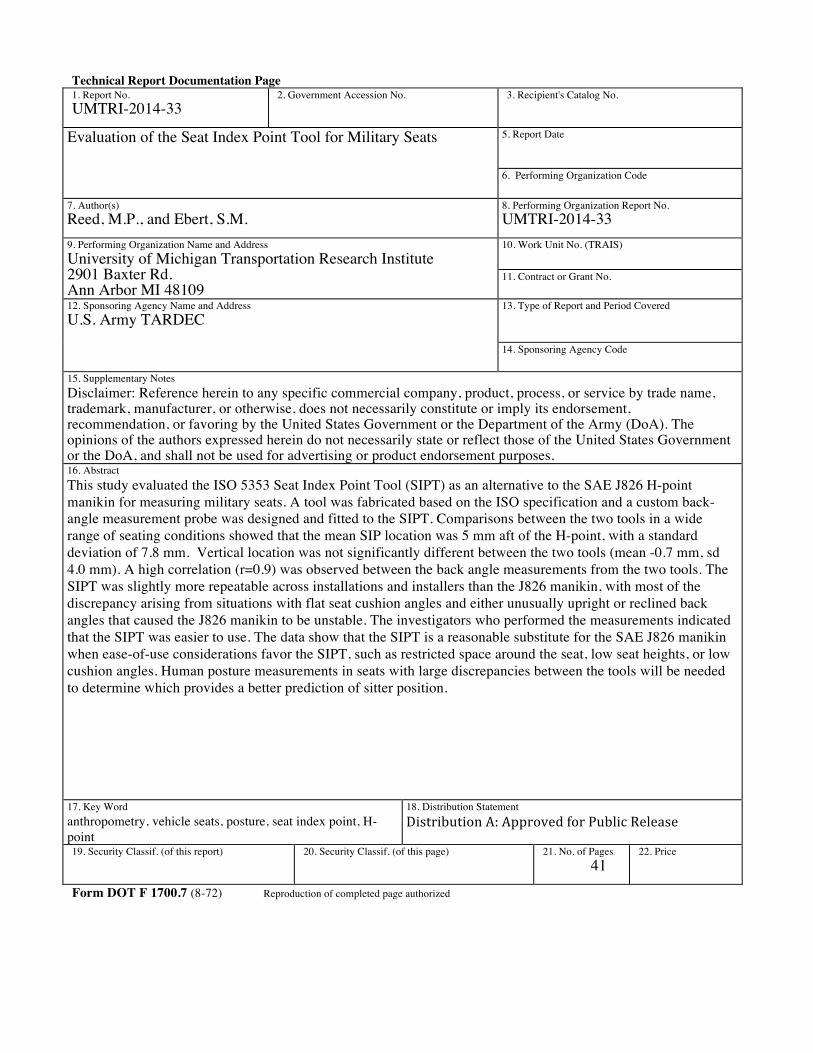
15. Supplementary Notes Disclaimer: Reference herein to any specific commercial company, product, process, or service by trade name, trademark, manufacturer, or otherwise, does not necessarily constitute or imply its endorsement, recommendation, or favoring by the United States Government or the Department of the Army (DoA). The opinions of the authors expressed herein do not necessarily state or reflect those of the United States Government or the DoA, and shall not be used for advertising or product endorsement purposes. 16. Abstract This study evaluated the ISO 5353 Seat Index Point Tool (SIPT) as an alternative to the SAE J826 H-point manikin for measuring military seats. A tool was fabricated based on the ISO specification and a custom back-angle measurement probe was designed and fitted to the SIPT. Comparisons between the two tools in a wide range of seating conditions showed that the mean SIP location was 5 mm aft of the H-point, with a standard deviation of 7.8 mm. Vertical location was not significantly different between the two tools (mean -0.7 mm, sd 4.0 mm). A high correlation (r=0.9) was observed between the back angle measurements from the two tools. The SIPT was slightly more repeatable across installations and installers than the J826 manikin, with most of the discrepancy arising from situations with flat seat cushion angles and either unusually upright or reclined back angles that caused the J826 manikin to be unstable. The investigators who performed the measurements indicated that the SIPT was easier to use. The data show that the SIPT is a reasonable substitute for the SAE J826 manikin when ease-of-use considerations favor the SIPT, such as restricted space around the seat, low seat heights, or low cushion angles. Human posture measurements in seats with large discrepancies between the tools will be needed to determine which provides a better prediction of sitter position.
17. Key Word anthropometry, vehicle seats, posture, seat index point, H-point
18. Distribution Statement Distribution!A:!Approved!for!Public!Release!
19. Security Classif. (of this report)
20. Security Classif. (of this page)
21. No. of Pages 41
22. Price
Form DOT F 1700.7 (8-72) Reproduction of completed page authorized
! 3!
Metric Conversion Chart
APPROXIMATE CONVERSIONS TO SI UNITS SYMBOL WHEN YOU KNOW MULTIPLY
BY TO FIND SYMBOL
LENGTH In inches 25.4 millimeters mm Ft feet 0.305 meters m Yd yards 0.914 meters m Mi miles 1.61 kilometers km
AREA in2 squareinches 645.2 square millimeters mm2 ft2 squarefeet 0.093 square meters m2 yd2 square yard 0.836 square meters m2 Ac acres 0.405 hectares ha mi2 square miles 2.59 square kilometers km2
VOLUME fl oz fluid
ounces 29.57 milliliters mL
gal gallons 3.785 liters L ft3 cubic
feet 0.028 cubic meters m3
yd3 cubic yards
0.765 cubic meters m3
NOTE: volumes greater than 1000 L shall be shown in m3 MASS
oz ounces 28.35 grams g lb pounds 0.454 kilograms kg T short
tons (2000 lb)
0.907 megagrams (or "metric ton")
Mg (or "t")
TEMPERATURE (exact degrees) oF Fahrenheit 5 (F-32)/9
or (F-32)/1.8 Celsius oC
FORCE and PRESSURE or STRESS lbf poundforce 4.45 newtons N
lbf/in2 poundforce per square
6.89 kilopascals kPa

! 4!
inch LENGTH
mm millimeters 0.039 inches in m meters 3.28 feet ft m meters 1.09 yards yd
km kilometers 0.621 miles mi AREA
mm2 square millimeters
0.0016 square inches
in2
m2 square meters 10.764 square feet
ft2
m2 square meters 1.195 square yards
yd2
ha hectares 2.47 acres ac km2 square
kilometers 0.386 square
miles mi2
VOLUME mL milliliters 0.034 fluid ounces fl oz L liters 0.264 gallons gal m3 cubic meters 35.314 cubic feet ft3 m3 cubic meters 1.307 cubic yards yd3
MASS g grams 0.035 ounces oz
kg kilograms 2.202 pounds lb Mg (or "t") megagrams (or
"metric ton") 1.103 short tons
(2000 lb) T
TEMPERATURE (exact degrees) oC Celsius 1.8C+32 Fahrenheit oF
FORCE and PRESSURE or STRESS N Newtons 0.225 poundforce lbf
kPa kilopascals 0.145 poundforce per square inch
lbf/in2
*SI is the symbol for the International System of Units. Appropriate rounding should be made to comply with Section 4 of ASTM E380. (Revised March 2003)
! 5!
ACKNOWLEDGMENTS
This research was supported by the Automotive Research Center (ARC) at the University of Michigan, under agreement W56H2V-14-2-0001 with the US Army Tank Automotive Research, Development, and Engineering Center in Warren, MI. The authors thank the assistance of TARDEC personnel who made this work possible, including Risa Scherer, Gale Litrichin, Kelly Bosch, Mike Megiveron, and Gale Zielinski.
! 6!
CONTENTS ACKNOWLEDGMENTS ...................................................................................................4 ABSTRACT .........................................................................................................................6 INTRODUCTION ...............................................................................................................7 METHODS ........................................................................................................................10 RESULTS ..........................................................................................................................25 DISCUSSION ....................................................................................................................30 CONCLUSIONS ...............................................................................................................35 REFERENCES ..................................................................................................................36 APPENDIX A. Installation Procedure ...............................................................................37 APPENDIX B. Back Angle Probe Design Drawing ........................................................41
! 7!
ABSTRACT
This study evaluated the ISO 5353 Seat Index Point Tool (SIPT) as an alternative to the SAE J826 H-point manikin for measuring military seats. A tool was fabricated based on the ISO specification and a custom back-angle measurement probe was designed and fitted to the SIPT. Comparisons between the two tools in a wide range of seating conditions showed that the mean SIP location was 5 mm aft of the H-point, with a standard deviation of 7.8 mm. Vertical location was not significantly different between the two tools (mean -0.7 mm, sd 4 mm). A high correlation (r=0.9) was observed between the back angle measurements from the two tools. The SIPT was slightly more repeatable across installations and installers than the J826 manikin, with most of the discrepancy arising from situations with flat seat cushion angles and either unusually upright or reclined back angles that caused the J826 manikin to be unstable. The investigators who performed the measurements indicated that the SIPT was easier to use. The data show that the SIPT is a reasonable substitute for the SAE J826 manikin when ease-of-use considerations favor the SIPT, such as restricted space around the seat, low seat heights, or low cushion angles. Human posture measurements in seats with large discrepancies between the tools will be needed to determine which provides a better prediction of sitter position.

! 8!
INTRODUCTION
The H-point manikin documented in SAE J826 was developed in the early 1960s in response to the need for a three-dimensional tool to represent vehicle occupants in the design process. Prior to that time, the standard reference point for taking seat dimensions was the “seat reference point” (SRP) located on the lateral seat centerline at the bight of the undeflected seat contour. The use of the SRP was problematic because the seat bight point was difficult to define and measure on seats with contoured surfaces. The relationship between the SRP and occupant positions also varied considerably across seats, both because of differences in seat contour and deformation under occupant loading.
The SAE J826 manikin, also called an H-point machine, addressed these issues by establishing a set of reference points and dimensions that could be more consistently related to occupant posture and position (see Reed et al. 1999 for a summary of the evolution of the H-point manikin). The manikin is constructed of rigid back and seat pans that simulate the human torso and thigh pivoting at hip or “H-point” with additional articulation points at the hip, knee and ankle. When the manikin is installed in a seat, body segment weights are applied to provide seat penetration equivalent to deflection a median male of 76 kg (167 lb). The thigh and leg segment lengths used for most measurements are similar to 95th percentile values for U.S. men. Figure 1 shows the SAE J826 H-point machine in use.
Figure 1. J826 H-point ready to be installed in a vehicle and measured with a CMM (left) and the J826 installed with weights in a vehicle (right).
The H-point manikin described in SAE J826 provides the H-point, a reference point used to predict the location of occupants in vehicles. The seating reference point (SgRP) defined in SAE J1100 locates the H-point in the vehicle workspace for drivers and passengers. SAE J1100 contains dozens of dimensions measured relative to the manikin.
! 9!
Federal Motor Vehicle Safety Standards (FMVSS) use the location of H-point for defining acceptable safety belt anchorage zones, and the H-point is used as a target for positioning crash test dummies prior to impact testing. The H-point manikin is also used to define and measure the seat back angle (SAE A40) and seat cushion angle (A27).
The H-point manikin is not widely used in the design and assessment of seats for military vehicles. In part, this is due to the lack of standards or guidelines requiring the use of a manikin-based reference point. MILSTD-1472G, which specifies human engineering requirements for military systems, bases dimension requirements for seats and vehicle driver workstations on a SRP similar to the reference point replaced by H-point in the 1960s.
In recent studies, UMTRI has used the J826 H-point manikin to establish reference points for quantifying Soldier posture and positioning, opening the way to more widespread use of the SAE tool in military seating (Reed and Ebert 2013). However, preliminary testing of the H-point manikin in military seats and vehicles demonstrated significant challenges. The H-point manikin could effectively be used in driver seats in truck-like vehicles, such as the HMMWV. However, the size and limited articulation of the manikin made it difficult or impossible to use in many squad seating conditions and in the driver seats of some vehicles. The H-point manikin is unstable in seats with seat back angles close to vertical and with flat, short seat cushions, particularly those with minimal deformation.
Consequently, the study team looked for alternative methods for establishing reference points in these situations. The SAE J4002 manikin, also known as H-point manikin (HPM) II, was considered. In the 1990s, the University of Michigan Transportation Research Institute (UMTRI) led an industry funded program to develop a new H-point manikin (Reed et al. 1999). The HPM-II was specifically developed to enable measurement of seats independent of the vehicle package by using optional, removable leg and foot components. The back section of the manikin is removable to facilitate installation, and the three-piece back articulates to conform to contoured seat backs. However, like the J826 manikin, the HPM-II is unstable with short, flat seat cushion and upright seat back angles. The HPM-II is also not widely available in industry and is expensive to purchase.
Consulting with colleagues in the off-highway seating industry led the team to consider the Seat Index Point Tool (SIPT). The SIPT is widely used to establish a reference point similar to the H-point in seats used for construction, forestry, agriculture, and other off-highway vehicles. SAE J1163 describes a SIPT that appears to have been developed to provide a reference point similar to that obtained with the H-point machine. However, discussions with seating colleagues indicated that the ISO 5353 SIPT, which has some differences in contour, is universally used in place of the J1163 version of the SIPT.
Based on this information, the current study was formulated with the objective of evaluating the ISO 5353 SIPT for applications to military vehicle seating in situations in which the J826 manikin could not be used. A SIPT was constructed based on the ISO specifications and a large series of tests were conducted to compare outcomes with the J826 H-point manikin. Because the ISO SIPT lacks the capability to measure back angle,

! 10!
a lightweight probe to measure the seat back angle in a manner analogous to the back angle measurement of the SAE J826 manikin was developed and tested.
Both the SIPT and H-point manikin provide a reference point in the general area in which a sitter’s hips are expected to lie. However, neither point should be interpreted as a hip point or a hip joint center location, because (1) the distribution of sitter’s hip locations relative to the SIP or H-point is affected by a number of variables, including body size and the presence of body armor, and (2) average hip locations are generally not collocated with these reference points. Instead, sitter hip locations and other aspects of posture are predicted relative to these reference points through measurements of sitters in a range of conditions. For more information on predicting Soldier posture relative to seat reference points, see Reed and Ebert (2013).

! 11!
METHODS
Comparing SAE J1163 and ISO 5353
The seat index point tool (SIPT) and procedure for using it is described in both SAE J1163 and ISO 5353. The SAE J1163 standard states that it is applicable to seats designed for off-road, self-propelled machines for agriculture and forestry as defined in ISO 3339-0. The SIP can be determined on a seat by itself or with the seat located in its operating environment. The ISO 5353 standard is applicable to seats designed for earth-moving machinery as defined in ISO 6165, and tractors and machinery. In both standards, the SIPT is a single-piece rigid buttock and thigh shell with a weight of 6 kg, without torso or legs. Weights are added to 40 mm forward of the SIP, bringing the total weight up to 65 kg, which is intended to represent the seat-borne weight of a midsize-male occupant. In these standards, the only measurement taken on the SIPT is the SIP and its location is often given relative to another reference point on the seat called a “fixing point,” interpreted as a mounting bolt or other designated reference feature.
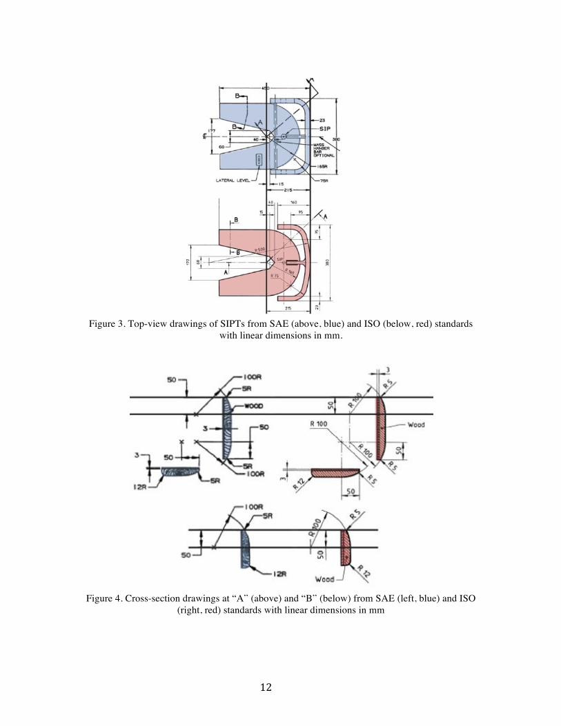
Figures 2- 4 show the technical drawings for the SIPTs side by side. The major difference between the two SIPTs is the shape of the vertical back. Figure 3 shows the more curved top-view shape of the ISO 5353 version. Based on information from industry that the ISO design is used exclusively both within the US and internationally, the ISO design was chosen for this study. Figure 5 shows the SIPT that UMTRI constructed based on the ISO drawings, and Figure 6 shows the tool installed in an forklift seat, one type of vehicle for which the tool is often used. Figure 7 illustrates the comparison of a scan of the SIPT relative to the ISO 5353 drawing. The tool is fabricated primarily of contoured wood with steel reinforcement. The weights were constructed of steel.
Figure 2. Side-view drawings of SIPT from SAE (above, blue) and ISO (below, red) standards with linear dimensions in mm
! 12!
Figure 3. Top-view drawings of SIPTs from SAE (above, blue) and ISO (below, red) standards
with linear dimensions in mm.
Figure 4. Cross-section drawings at “A” (above) and “B” (below) from SAE (left, blue) and ISO
(right, red) standards with linear dimensions in mm

! 13!
Figure 5. ISO 5353 SIPT fabricated for this study.
Figure 6. SIPT in a fork lift seat with short back and seat cushion lengths shown resting on the seat without weights (left) and fully installed (right).

! 14!
Figure 7. UMTRI SIPT 3D scan (red) compared to ISO 5353 standard drawings (black line
drawing)
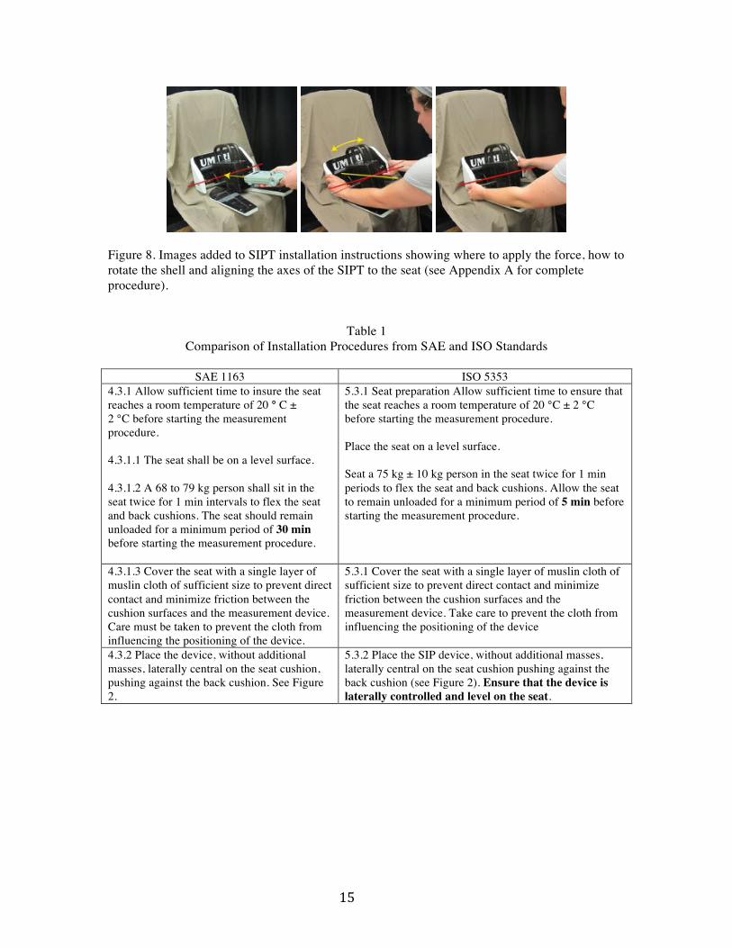
After the SIPT was built, the installation procedures for both the J1163 and ISO 5353 were evaluated for applicability to military seats. Table 1 lists the installation procedures side by side. The ISO SIPT and its procedure were given to people with and without knowledge of J826 and the individuals were observed performing an installation. Due to the range of interpretations of the procedure, images and additional text were added to create the installation procedure in Appendix A. This procedure was followed during subsequent data collection. Key clarifications included the images in Figure 8 on where to apply load and which axis to rotate the SIPT around. More direction was also provided on aligning the SIPT with the axes of the seat.
! 15!
Figure 8. Images added to SIPT installation instructions showing where to apply the force, how to rotate the shell and aligning the axes of the SIPT to the seat (see Appendix A for complete procedure).
Table 1 Comparison of Installation Procedures from SAE and ISO Standards
SAE 1163 ISO 5353
4.3.1 Allow sufficient time to insure the seat reaches a room temperature of 20 ° C ± 2 °C before starting the measurement procedure. 4.3.1.1 The seat shall be on a level surface. 4.3.1.2 A 68 to 79 kg person shall sit in the seat twice for 1 min intervals to flex the seat and back cushions. The seat should remain unloaded for a minimum period of 30 min before starting the measurement procedure.
5.3.1 Seat preparation Allow sufficient time to ensure that the seat reaches a room temperature of 20 °C ± 2 °C before starting the measurement procedure. Place the seat on a level surface. Seat a 75 kg ± 10 kg person in the seat twice for 1 min periods to flex the seat and back cushions. Allow the seat to remain unloaded for a minimum period of 5 min before starting the measurement procedure.
4.3.1.3 Cover the seat with a single layer of muslin cloth of sufficient size to prevent direct contact and minimize friction between the cushion surfaces and the measurement device. Care must be taken to prevent the cloth from influencing the positioning of the device.
5.3.1 Cover the seat with a single layer of muslin cloth of sufficient size to prevent direct contact and minimize friction between the cushion surfaces and the measurement device. Take care to prevent the cloth from influencing the positioning of the device
4.3.2 Place the device, without additional masses, laterally central on the seat cushion, pushing against the back cushion. See Figure 2.
5.3.2 Place the SIP device, without additional masses, laterally central on the seat cushion pushing against the back cushion (see Figure 2). Ensure that the device is laterally controlled and level on the seat.

! 16!
4.3.2.1 Add masses to bring the total mass of the device from 6 kg ± 1 to 26 kg ± 1; the vertical force center of the added masses shall be 40 mm in front of the SIP mark on the horizontal section of the device. See Figure 1.
5.3.2 Add masses to bring the total mass of the device from 6 kg ± 1 kg to 26 kg ± 1 kg; the vertical force centre of the added masses shall be 40 mm in front of the SIP mark on the horizontal section of the device (see Figure 1).
4.3.2.2 To obtain a good fit between the seat cushion, the back cushion, and the SIP measuring device, alternatingly apply and release a horizontal and rearward force of approximately 100 N at the location noted in Figure 1, and rock the device from side to side.
5.3.2 To obtain a good fit between the seat cushion, the back cushion, and the SIP measuring device, alternately apply and release a horizontal rearward force of approximately 100 N at the location noted in Figure 1, and rock the device from side to side.
4.3.2.3 Add further masses to bring the total mass of the device from 26 kg ± 1 kg to 65 kg ± 1 kg. NOTE- A 75 kg operator approximates the 65 kg weighted device on the seat.
5.3.2 Add further masses to bring the total mass of the device from26 kg ± 1 kg to 65 kg ± 1 kg such that the vertical force centre of the additional masses is 40 mm in front of the SIP mark on the horizontal section of the device (see Figure 1). NOTE 3 - A 75 kg operator approximates the 65 kg weighted device on the seat.
4.3.2.4 Repeat the alternate loading, releasing, and the rocking of the device as defined in 4.3.2.2, checking to make sure the device is laterally central and level on the seat.
5.3.2 Repeat the alternate loading and releasing, and the rocking of the device, checking to make sure the device is laterally central and level on the seat.
4.3.3 Measurements shall be made on each side of the SIP measuring device at points equal distance from the central vertical plane. See Figure 2. Average the values. Record within ±1 mm the coordinate dimensions of the SIP from the fixing point on the seat assembly, see Figure 3, that is defined by the manufacturer.
5.3.3 Make measurements on each side of the SIP measuring device at points an equal distance from the central vertical plane (see Figure 2). Average the values. Record within ± 1 mm the coordinate dimensions of the SIP from the fixing point on the seat assembly (see Figure 3) that is defined by the manufacturer.
! 17!
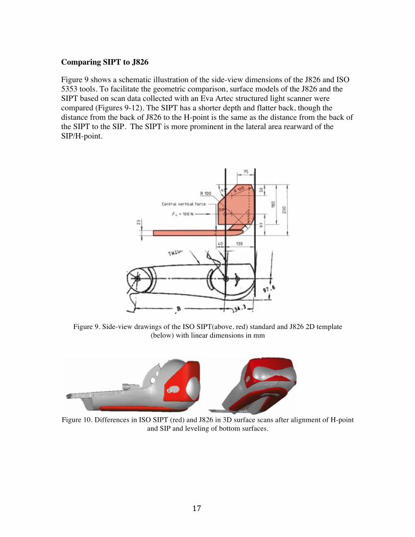
Comparing SIPT to J826
Figure 9 shows a schematic illustration of the side-view dimensions of the J826 and ISO 5353 tools. To facilitate the geometric comparison, surface models of the J826 and the SIPT based on scan data collected with an Eva Artec structured light scanner were compared (Figures 9-12). The SIPT has a shorter depth and flatter back, though the distance from the back of J826 to the H-point is the same as the distance from the back of the SIPT to the SIP. The SIPT is more prominent in the lateral area rearward of the SIP/H-point.
Figure 9. Side-view drawings of the ISO SIPT(above, red) standard and J826 2D template (below) with linear dimensions in mm
Figure 10. Differences in ISO SIPT (red) and J826 in 3D surface scans after alignment of H-point
and SIP and leveling of bottom surfaces.

! 18!
Figure 11. Heat map of the difference between the SIPT and J826. Units in millimeters.
Figure 12. Three-dimensional views of J826 and SIPT overlaid.
! 19!
Using the SIPT to Measure Back Angle
One important limitation of the ISO 5353 manikin for the current application is that it lacks the capability of measuring seat back angle. Because a fixed seat back angle has a strong influence on sitter posture (Reed and Ebert 2013), a back angle measurement is needed for military seating applications. The goals of the development effort were (1) create an easy-to-use add-on for the SIPT that did not change the performance of the SIPT, (2) obtain a measure well correlated with the J826 back angle measure in seats for which both tools could be used.
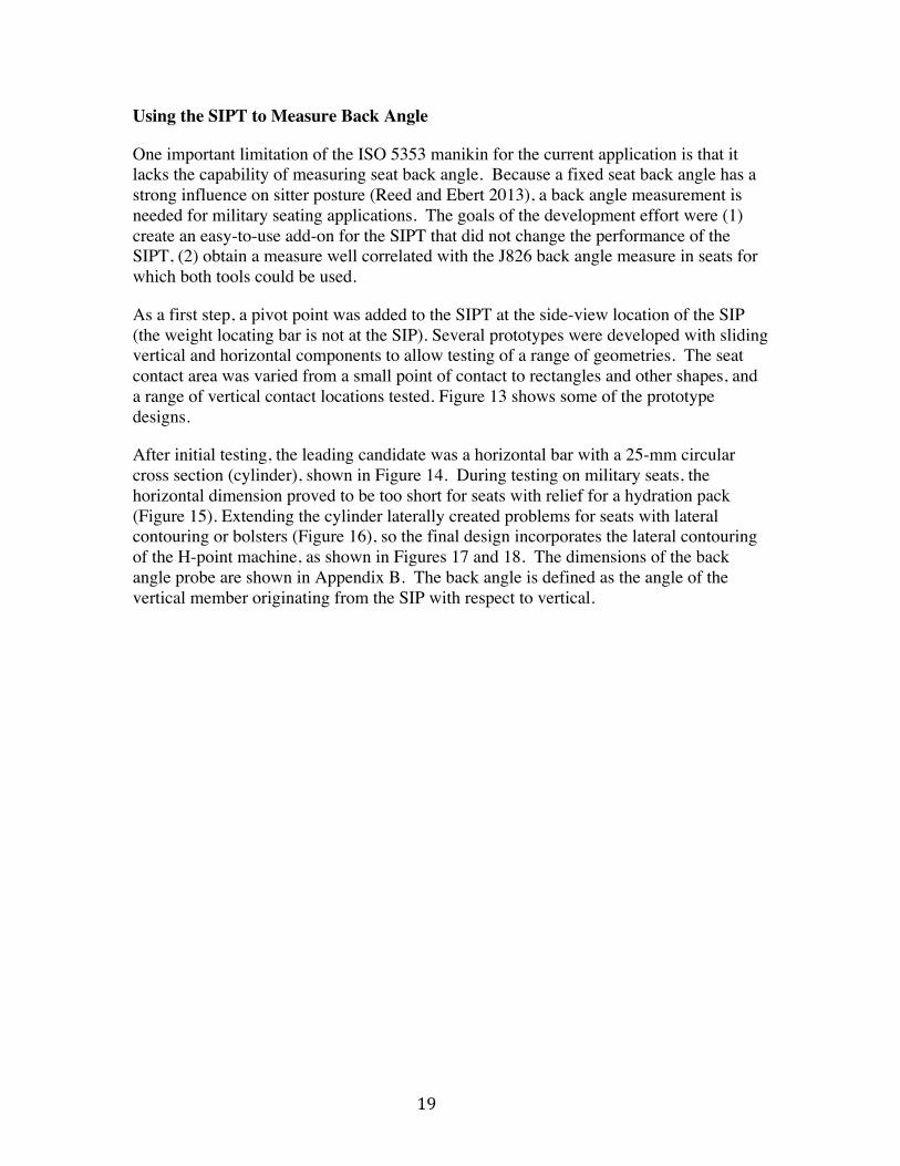
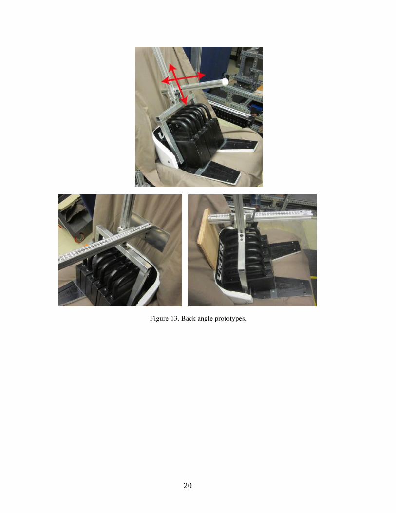
As a first step, a pivot point was added to the SIPT at the side-view location of the SIP (the weight locating bar is not at the SIP). Several prototypes were developed with sliding vertical and horizontal components to allow testing of a range of geometries. The seat contact area was varied from a small point of contact to rectangles and other shapes, and a range of vertical contact locations tested. Figure 13 shows some of the prototype designs.
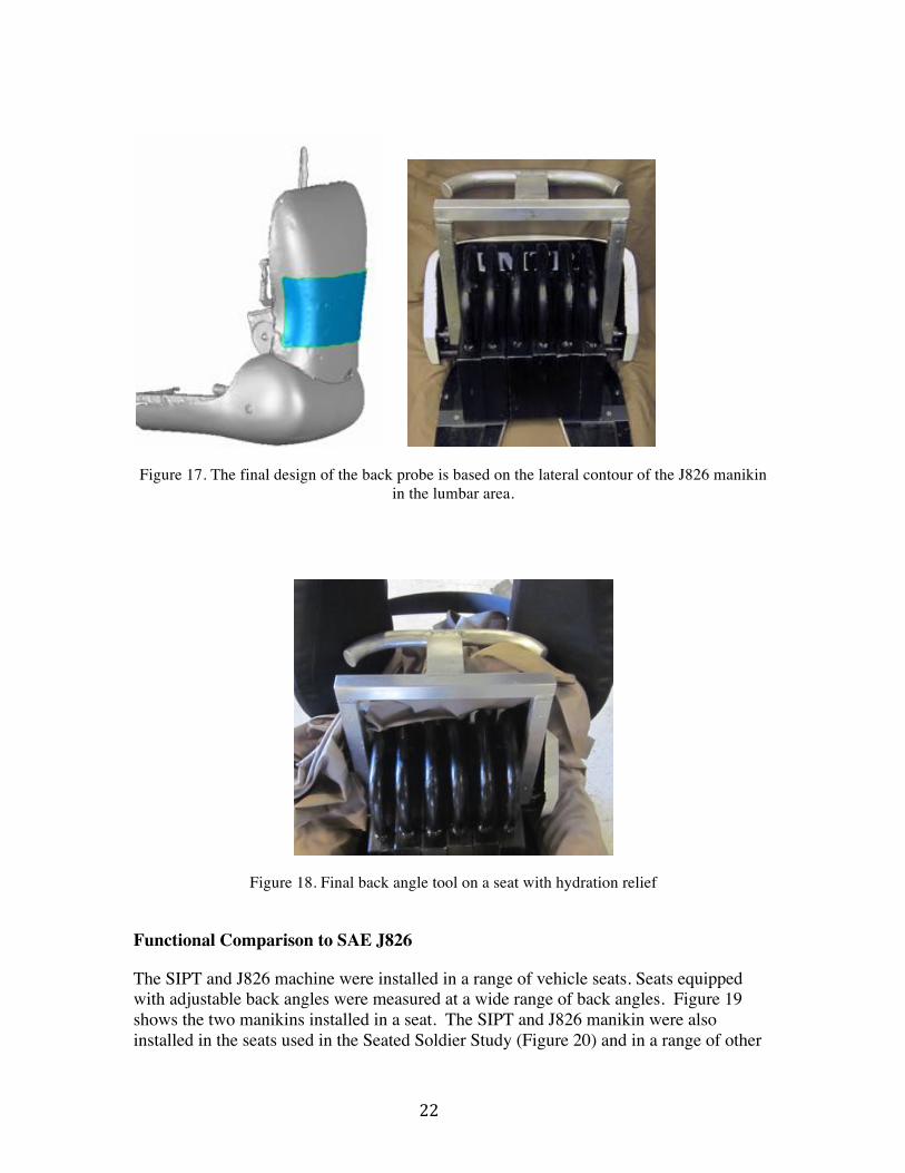
After initial testing, the leading candidate was a horizontal bar with a 25-mm circular cross section (cylinder), shown in Figure 14. During testing on military seats, the horizontal dimension proved to be too short for seats with relief for a hydration pack (Figure 15). Extending the cylinder laterally created problems for seats with lateral contouring or bolsters (Figure 16), so the final design incorporates the lateral contouring of the H-point machine, as shown in Figures 17 and 18. The dimensions of the back angle probe are shown in Appendix B. The back angle is defined as the angle of the vertical member originating from the SIP with respect to vertical.
! 20!
Figure 13. Back angle prototypes.

! 21!
Figure 14. “Alpha” prototype for military seat testing.
Figure 15. Alpha prototype on seats with hydration relief.
Figure 16. Attempts to change geometry. Extend straight or create a rounded surface
! 22!
Figure 17. The final design of the back probe is based on the lateral contour of the J826 manikin in the lumbar area.
Figure 18. Final back angle tool on a seat with hydration relief
Functional Comparison to SAE J826
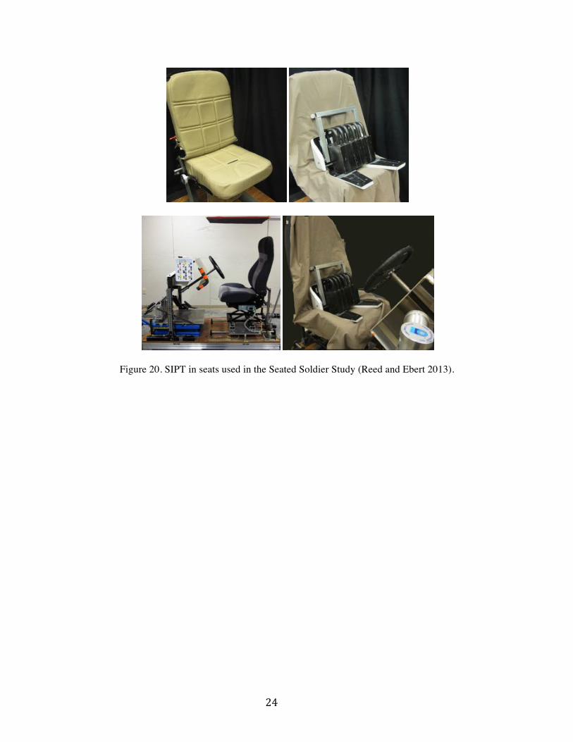
The SIPT and J826 machine were installed in a range of vehicle seats. Seats equipped with adjustable back angles were measured at a wide range of back angles. Figure 19 shows the two manikins installed in a seat. The SIPT and J826 manikin were also installed in the seats used in the Seated Soldier Study (Figure 20) and in a range of other

! 23!
military vehicle seats (Figure 21). In each case, a FARO Arm coordinate digitizer was used to record the left and right H-point or SIP locations. An electronic inclinometer was applied to manikin or SIPT surfaces to measure seat cushion angle and seat back angle. The data were analyzed to compare J826 and SIPT measures and to assess repeatability and reproducibility.
Figure 19. Installing SIPT and J826 in a military seat. The FARO Arm used to record SIP and H-
point locations is shown.
! 24!
Figure 20. SIPT in seats used in the Seated Soldier Study (Reed and Ebert 2013).
! 25!
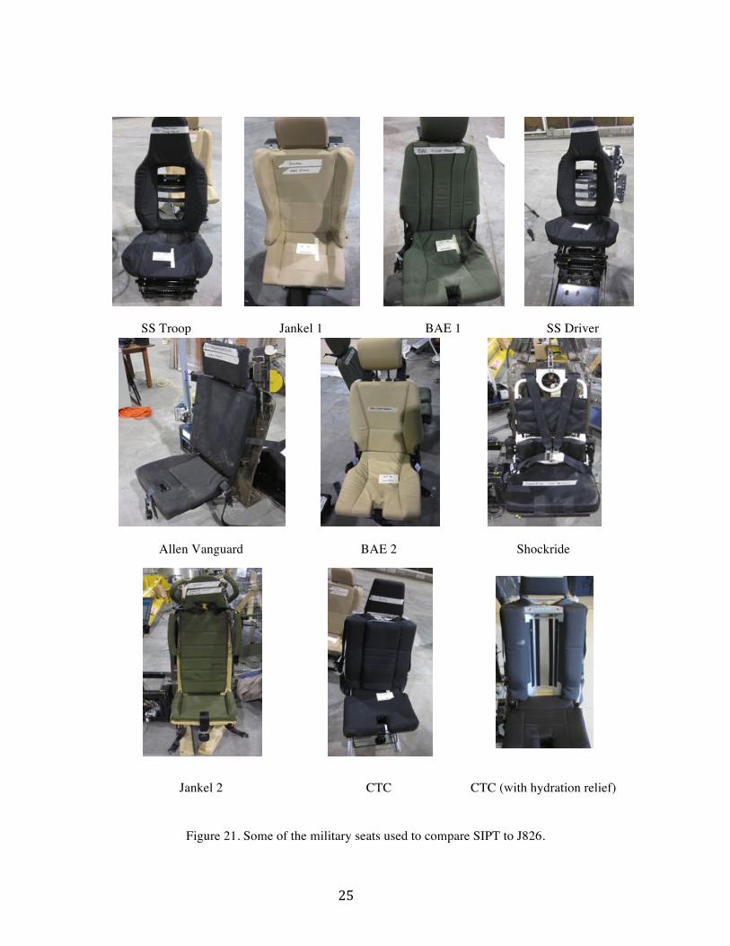
SS Troop Jankel 1 BAE 1 SS Driver
Allen Vanguard BAE 2 Shockride
Jankel 2 CTC CTC (with hydration relief)
Figure 21. Some of the military seats used to compare SIPT to J826.

! 26!
RESULTS
H-Point vs. SIP Figure 22 shows the position of the SIPT relative to H-point in the installations in all seats and conditions. The SIPT was on average 5 mm rearward of H-point (sd 7.8) but no significant difference in vertical location was observed (mean -0.7, sd 4.0 mm). In three of the test conditions, the SIP was more than 20 mm rearward of the H-point.
Figure 22. Comparison of SIP relative to J826. Positive values indicate that the SIP was
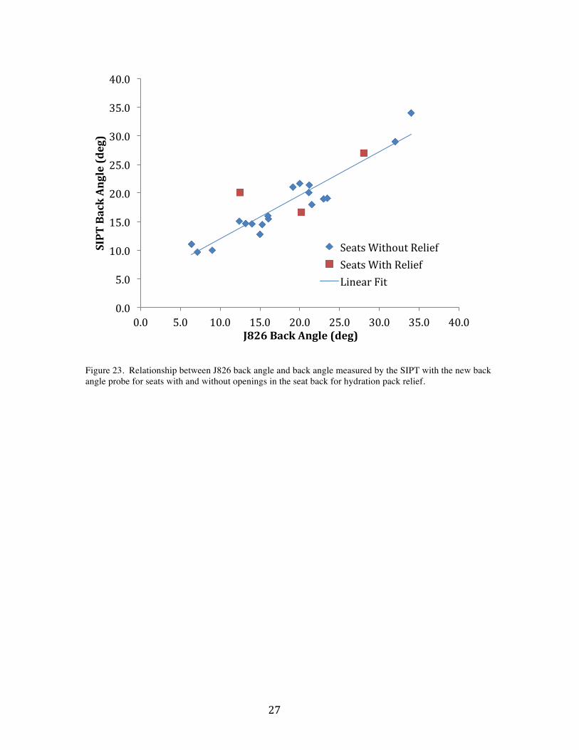
rearward of the H-point. Back Angle Measurement The plot in Figure 23 shows the relationship between the seat back angle measured with the SIPT relative to the J826, demonstrating a strong correlation (r = 0.92). The functional relationship is given by SIPT back angle = 0.764 (J826 back angle) + 4.3 R2 = 0.843, RMSE = 2.3 and J826 back angle = 1.103 (SIPT back angle) -1.91 R2 = 0.843, RMSE = 2.8
A15.0!
A10.0!
A5.0!
0.0!
5.0!
10.0!
A10.0! A5.0! 0.0! 5.0! 10.0! 15.0! 20.0! 25.0! 30.0! 35.0!
Z"Difference"in"mm"(SIPT"0"J826)"
X"Difference"in"mm"(SIPT"0"J826)"
Lab!Seats!Military!Seats!Mean!+/A!1!SD!
! 27!
Figure 23. Relationship between J826 back angle and back angle measured by the SIPT with the new back angle probe for seats with and without openings in the seat back for hydration pack relief.
0.0!
5.0!
10.0!
15.0!
20.0!
25.0!
30.0!
35.0!
40.0!
0.0! 5.0! 10.0! 15.0! 20.0! 25.0! 30.0! 35.0! 40.0!
SIPT"Back"Angle"(deg)"
J826"Back"Angle"(deg)"
Seats!Without!Relief!Seats!With!Relief!Linear!Fit!

! 28!
Repeatability and Reproducibility
Comparison Data
In previous work at UMTRI and corporate collaborators, an extensive study was conducted to assess the repeatability and reproducibility of the J826 and J4002 manikins (Flannagan 2005). The numbers in Table 2 represent variability from “well-trained, experienced operators” for comparison with the data from the current study. The average standard deviation of H-point location is less than 3 mm in the X (fore-aft) coordinate and less than 2 mm in Z (vertical) coordinate.
Table 2 Summary Table of J826 Manikin Installation Repeatability and Reproducibility (Flannagan 2005)
Standard Deviation of Measurement
Measure Back Angle
(deg) X: Fore-aft
(mm) Z: Vertical
(mm) Reproducibility 0.80 1.31 1.38 Repeatability 0.66 1.77 0.87 Manikin 0.09 0.19 0.44 Combined* 1.04 2.21 1.69 * Combined value is square root of sum of variances (standard deviation squared) for reproducibility, repeatability, and manikin.
Repeatability within Investigator
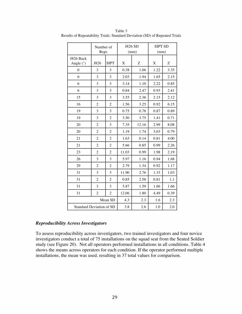
Repeatability was assessed by 2 trained investigators and 4 more novice investigators on 2 passenger vehicle seats (one of which was adjusted to different back and cushion angles) and 6 military seats, 2 of which had hydration relief. In each seating condition, two or three installations were performed by the same investigator. The standard deviations of H-point and SIP locations across these trials within condition are listed in Table 3. The SIP was somewhat more repeatable (lower standard deviation) on the fore-aft (X) coordinate; the mean repeatability was the same on the vertical coordinate. Overall, across seating conditions, the SIPT was judged to be at least as repeatable as the industry standard J826 manikin. High standard deviations in fore-aft H-point location (X coordinate) were observed in 3 seats with relatively high seat back angles, whereas the SIP locations in the same conditions were more consistent. The repeatability for both tools observed in the current study is comparable to that reported for the J826 manikin by Flannagan (2005).
! 29!
Table 3 Results of Repeatability Trials: Standard Deviation (SD) of Repeated Trials
Reproducibility Across Investigators
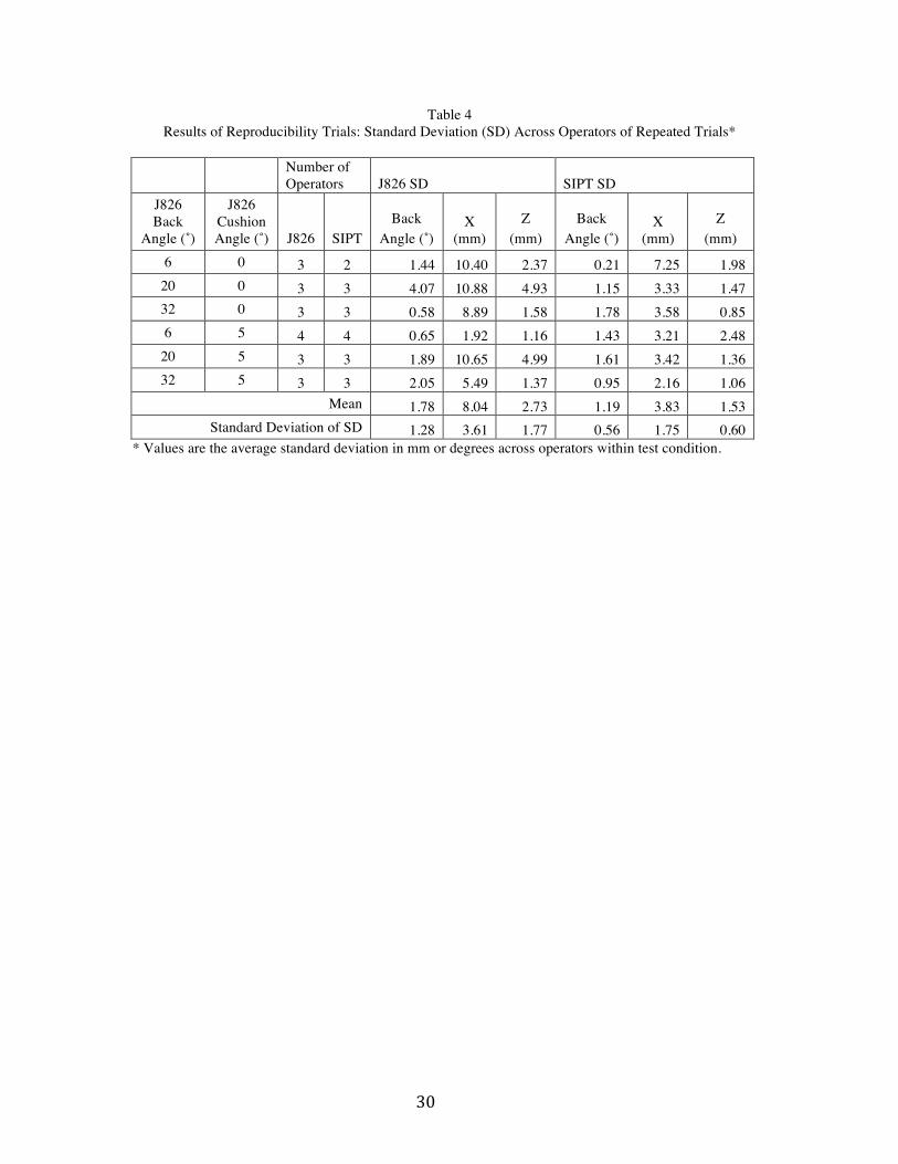
To assess reproducibility across investigators, two trained investigators and four novice investigators conduct a total of 75 installations on the squad seat from the Seated Soldier study (see Figure 20). Not all operators performed installations in all conditions. Table 4 shows the means across operators for each condition. If the operator performed multiple installations, the mean was used, resulting in 37 total values for comparison.
Number of Reps
J826 SD (mm)
SIPT SD (mm)
J826 Back Angle (˚) J826 SIPT X Z X Z
0 3 3 0.38 1.06 1.22 3.35
6 3 3 2.03 1.94 1.65 2.15
6 3 3 3.14 1.10 2.22 0.85
6 3 3 0.84 2.47 0.93 2.41
15 3 3 3.55 2.36 2.15 2.12
16 2 2 1.56 3.25 0.92 6.15
19 3 3 0.75 0.78 0.87 0.89
19 3 2 3.50 3.75 1.41 0.71
20 2 3 7.35 12.16 2.99 8.08
20 2 2 1.19 1.74 3.03 0.79
21 2 2 1.63 0.14 0.81 4.00
21 2 2 5.66 0.85 0.99 2.26
23 2 2 11.03 0.99 1.98 2.19
26 3 3 5.97 1.16 0.94 1.68
29 2 2 2.79 1.34 0.92 1.17
31 3 3 11.90 2.76 1.33 1.03
31 2 2 0.85 2.58 0.81 1.1
31 3 3 5.87 1.59 1.66 1.66
31 2 2 12.06 1.80 4.49 0.39
Mean SD 4.3 2.3 1.6 2.3
Standard Deviation of SD 3.8 2.6 1.0 2.0
! 30!
Table 4 Results of Reproducibility Trials: Standard Deviation (SD) Across Operators of Repeated Trials*
Number of Operators J826 SD SIPT SD
J826 Back
Angle (˚)
J826 Cushion Angle (˚) J826 SIPT
Back Angle (˚)
X (mm)
Z (mm)
Back Angle (˚)
X (mm)
Z (mm)
6 0 3 2 1.44 10.40 2.37 0.21 7.25 1.98 20 0 3 3 4.07 10.88 4.93 1.15 3.33 1.47 32 0 3 3 0.58 8.89 1.58 1.78 3.58 0.85 6 5 4 4 0.65 1.92 1.16 1.43 3.21 2.48
20 5 3 3 1.89 10.65 4.99 1.61 3.42 1.36 32 5 3 3 2.05 5.49 1.37 0.95 2.16 1.06
Mean 1.78 8.04 2.73 1.19 3.83 1.53 Standard Deviation of SD 1.28 3.61 1.77 0.56 1.75 0.60
* Values are the average standard deviation in mm or degrees across operators within test condition.
! 31!
DISCUSSION
Tool Shape and Construction A quantitative comparison showed that the contours of the SIPT and J826 manikin are similar in the areas they share. When the SIP and H-point are aligned, and the bottom surfaces are set to be parallel, the SIPT contour is more prominent in the area rearward the H-point, particularly on the sides, and extends somewhat lower. The back angle measurement probe developed in this study uses a contour developed from the J826 manikin. The SIPT differs from the J826 manikin in having a lower center of mass and a more concentrated mass. The J826 manikin has legs and weights that are applied to the distal thigh and proximal leg during installation. The effects of these weights on installations with the manikin varies depending on the particular lower extremity posture, and hence it’s not possible to generalize as to their effects. However, as discussed below, the combination of the mass distribution and geometry of the J826 manikin makes it unstable in important conditions of interest. Usage
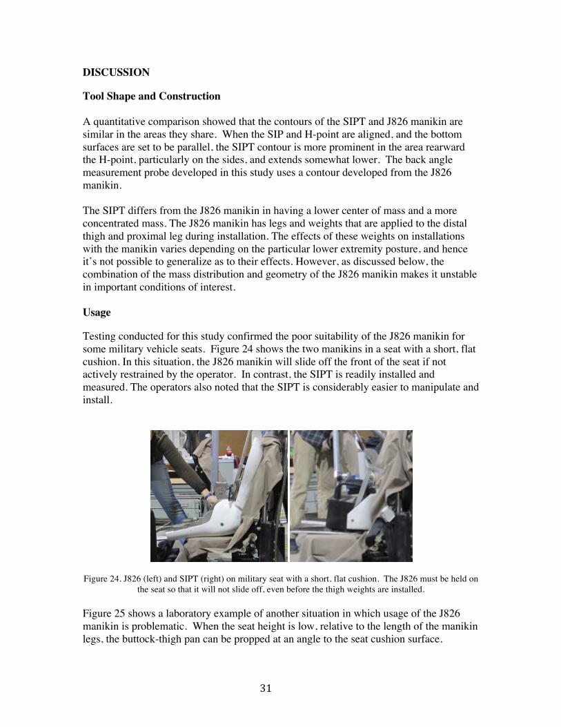
Testing conducted for this study confirmed the poor suitability of the J826 manikin for some military vehicle seats. Figure 24 shows the two manikins in a seat with a short, flat cushion. In this situation, the J826 manikin will slide off the front of the seat if not actively restrained by the operator. In contrast, the SIPT is readily installed and measured. The operators also noted that the SIPT is considerably easier to manipulate and install.
Figure 24. J826 (left) and SIPT (right) on military seat with a short, flat cushion. The J826 must be held on the seat so that it will not slide off, even before the thigh weights are installed.
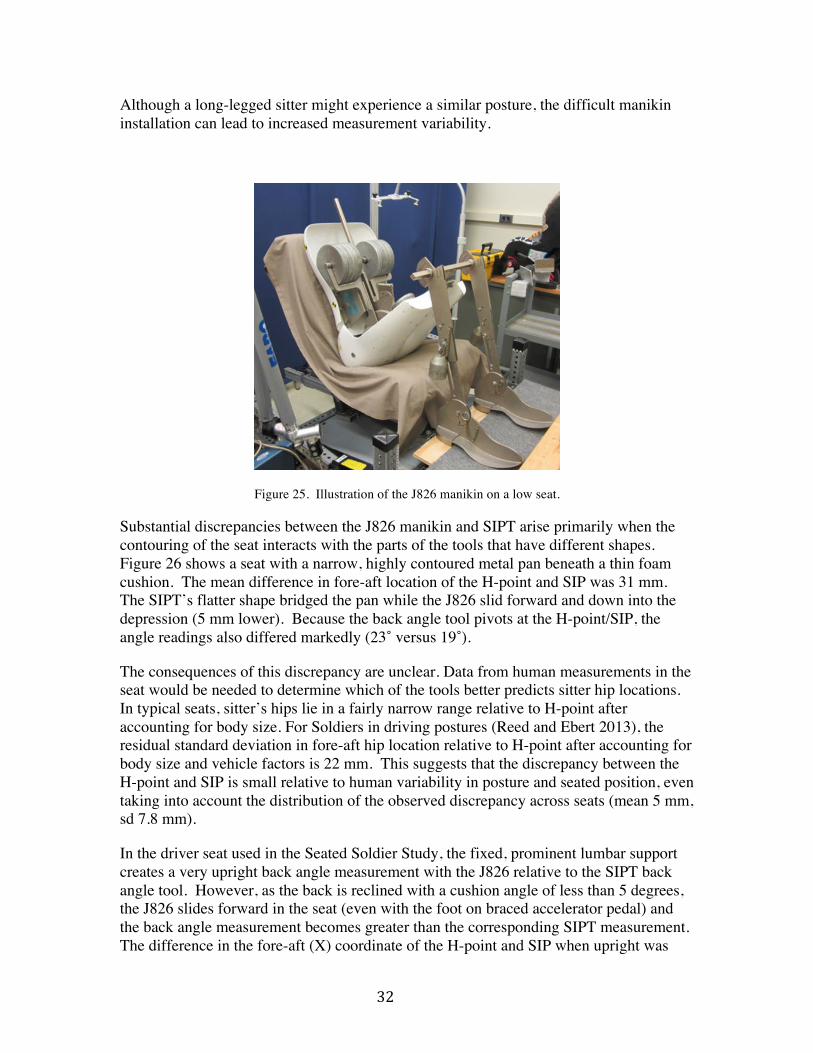
Figure 25 shows a laboratory example of another situation in which usage of the J826 manikin is problematic. When the seat height is low, relative to the length of the manikin legs, the buttock-thigh pan can be propped at an angle to the seat cushion surface.
! 32!
Although a long-legged sitter might experience a similar posture, the difficult manikin installation can lead to increased measurement variability.
Figure 25. Illustration of the J826 manikin on a low seat.
Substantial discrepancies between the J826 manikin and SIPT arise primarily when the contouring of the seat interacts with the parts of the tools that have different shapes. Figure 26 shows a seat with a narrow, highly contoured metal pan beneath a thin foam cushion. The mean difference in fore-aft location of the H-point and SIP was 31 mm. The SIPT’s flatter shape bridged the pan while the J826 slid forward and down into the depression (5 mm lower). Because the back angle tool pivots at the H-point/SIP, the angle readings also differed markedly (23˚ versus 19˚).
The consequences of this discrepancy are unclear. Data from human measurements in the seat would be needed to determine which of the tools better predicts sitter hip locations. In typical seats, sitter’s hips lie in a fairly narrow range relative to H-point after accounting for body size. For Soldiers in driving postures (Reed and Ebert 2013), the residual standard deviation in fore-aft hip location relative to H-point after accounting for body size and vehicle factors is 22 mm. This suggests that the discrepancy between the H-point and SIP is small relative to human variability in posture and seated position, even taking into account the distribution of the observed discrepancy across seats (mean 5 mm, sd 7.8 mm).
In the driver seat used in the Seated Soldier Study, the fixed, prominent lumbar support creates a very upright back angle measurement with the J826 relative to the SIPT back angle tool. However, as the back is reclined with a cushion angle of less than 5 degrees, the J826 slides forward in the seat (even with the foot on braced accelerator pedal) and the back angle measurement becomes greater than the corresponding SIPT measurement. The difference in the fore-aft (X) coordinate of the H-point and SIP when upright was

! 33!
about 6 mm but over 25 mm when reclined. Posture data from the study do not show that drivers’ hips are further forward at more-reclined back angles, suggesting that the SIP may provide a more consistent predictor of driver locations for seats that have low seat cushion angles and prominent lumbar supports.
Effects of Gear
Like the H-point machine, the SIPT provides a reference point relative to the seat that does not account for body armor or body borne gear. These effects are taken into account when predicting human posture, position, and accommodation relative to the seat. For example, the Seated Soldier study documented Soldier hip locations relative to H-point for three ensemble levels (Reed and Ebert 2013). In general, adding body armor and body borne gear shifts Soldiers forward on the seat. Because the measurement tool (SIPT or H-point machine) is independent of any particular gear ensemble or Soldier body size, the reference points are useful across a wide range of scenarios and not tied to one particular ensemble.
Some seat designs intended to accommodate particular gear ensembles may affect the relationship between the SIP and the Soldier. For example, the Rifleman ensemble used in the Seated Soldier Study included a hydration pack worn on the upper back. In the seats used in that study, the result was a forward shift of the Soldier’s position on the seat. In contrast, a seat with an opening for the hydration pack could reduce or eliminate the effect of the pack on Soldier position in the seat. More study with Soldiers will be needed to determine the extent to which seat design features such as these affect Soldier positions. In any case, obtaining SIP data from the same seats used in Soldier studies will allow the resulting relationships to be quantified.

! 34!
Figure 26. A seat that produced a substantial discrepancy between H-point and SIP due to a narrow, highly contoured seat pan.

! 35!
If a seat has hydration relief that extends down to or close to the seat bight, the opening may affect the two manikins differently, depending on the dimensions of the cutout. No strong effect was observed across the seats in the current study, but seats with different dimensions could produce some discrepancy in fore-aft location. Human posture data would be needed to determine which tool provided a more consistent measure of sitter location in these conditions.
Figure 27 shows an unusually constructed seat that has a support across the lower back that is constructed to help support the sitter’s body armor. In this seat, neither tool could be positioned full-rear on the seat pan. The cushion, which was not rigidly attached to the frame, slid forward during the installation of the J826 manikin, which is probably not representative of the way a sitter would use the seat. However, the SIPT was readily installed without the seat cushion shifting.
Figure 27. Seat with armor support and a floating cushion.
! 36!
CONCLUSIONS
1. The ISO 5353 SIPT is similar in contour to the J826 manikin in areas they share. The discrepancies may have a small influence on the difference between SIP and H-point, but installation differences are usually more important. We were able to fabricate and verify the tool design effectively using the information in the standard.
2. We developed a back angle measurement add-on that produces a measurement that is well correlated with the J826 back angle. Linear equations to estimate one from the other are provided in this report. The new tool is more effective in seats with relatively upright back angles than is the J826 manikin, which becomes unstable in such seats.
3. The SIP and J826 H-points are in similar positions across a wide range of seating conditions. On average the fore-aft discrepancy is 5 mm. No mean vertical discrepancy was observed. In the absence of actual H-point measurement, the H-point can be approximated by a point 5 mm forward of the SIP.
4. The repeatability and reproducibility of the two tools is similar, except that the SIPT is more repeatable in seats with seat cushion angles close to horizontal and with both very upright and very reclined seat back angles.
5. Certain seat features can increase the discrepancy between the two tools, including narrow seat cushion bolsters, flat seat cushion angles, and highly reclined seat back angles.
6. Overall, the SIPT is easier to use than the J826 manikin.
7. Human posture measurement will be needed to determine the consistency of the SIP with respect sitter positions in seats in which the two tools diverge.
8. More research is needed to determine appropriate reference points to predict human positioning in seats for which neither tool is effective. No such seats were examined in the current study.
9. The current findings, combined with the extensive use of the tool for off-highway equipment over many years, supports immediate adoption of the SIPT for military vehicle seats for situations in which the J826 manikin cannot be used. Given the usability and other advantages of the SIP, including stability in certain seat configurations, the Army should give consideration to adopting the SIPT as a measurement tool for all vehicle seats.
! 37!
REFERENCES
Flannagan, C., (2005). Reproducibility and repeatability of the SAE J4002 and J826 H-point machines, SAE Technical Paper 2005-01-1010, SAE International, Warrendale, PA.
Manary, M.A., Schneider, L.W., Flannagan, C.A.C., and Eby, B.A.H. (1994). Evaluation of the SAE J826 3-D manikin measures of driver positioning and posture. Technical Paper No. 941048. SAE International, Warrendale, PA.
Reed, M.P., Roe, R.W, and Schneider, L.W. (1999). Design and development of the ASPECT manikin. SAE Transactions: Journal of Passenger Cars, 108: 1800-1817.
Reed, M.P. and Ebert, S.M (2013). The Seated Soldier Study: Posture and Body Shape In Vehicle Seats. Final Report UMTRI-2013-13. University of Michigan Transportation Research Institute, Ann Arbor, MI
! 38!
APPENDIX A Installation Procedure
Photo Instructions
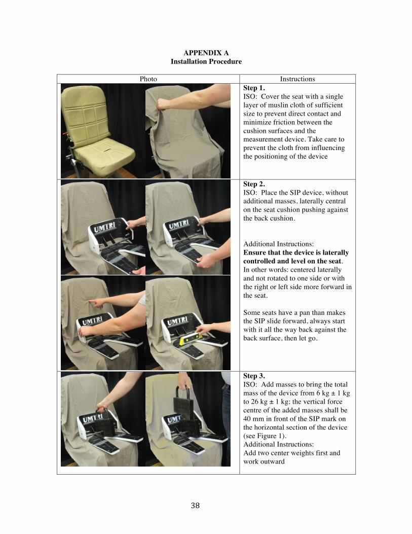
Step 1. ISO: Cover the seat with a single layer of muslin cloth of sufficient size to prevent direct contact and minimize friction between the cushion surfaces and the measurement device. Take care to prevent the cloth from influencing the positioning of the device
Step 2. ISO: Place the SIP device, without additional masses, laterally central on the seat cushion pushing against the back cushion. Additional Instructions: Ensure that the device is laterally controlled and level on the seat. In other words: centered laterally and not rotated to one side or with the right or left side more forward in the seat. Some seats have a pan than makes the SIP slide forward, always start with it all the way back against the back surface, then let go.
Step 3. ISO: Add masses to bring the total mass of the device from 6 kg ± 1 kg to 26 kg ± 1 kg; the vertical force centre of the added masses shall be 40 mm in front of the SIP mark on the horizontal section of the device (see Figure 1). Additional Instructions: Add two center weights first and work outward

! 39!
Step 4. ISO: To obtain a good fit between the seat cushion, the back cushion, and the SIP measuring device, alternately apply and release a horizontal rearward force of approximately 100 N at the location noted in Figure 1, and rock the device from side to side.
Additional Instructions: Side to side= around “X” axis or from left to right Careful not to pull the SIP forward or push rearward.
Step 5. ISO: Add further masses to bring the total mass of the device from 26 kg ± 1 kg to 65 kg ± 1 kg such that the vertical force center of the additional masses is 40 mm in front of the SIP mark on the horizontal section of the device (see Figure 1). Repeat the alternate loading and releasing, and the rocking of the device, checking to make sure the device is laterally central and level on the seat. Additional Notes: Load symmetrically Steps 3 and 4 repeated with each two weights added
! 40!
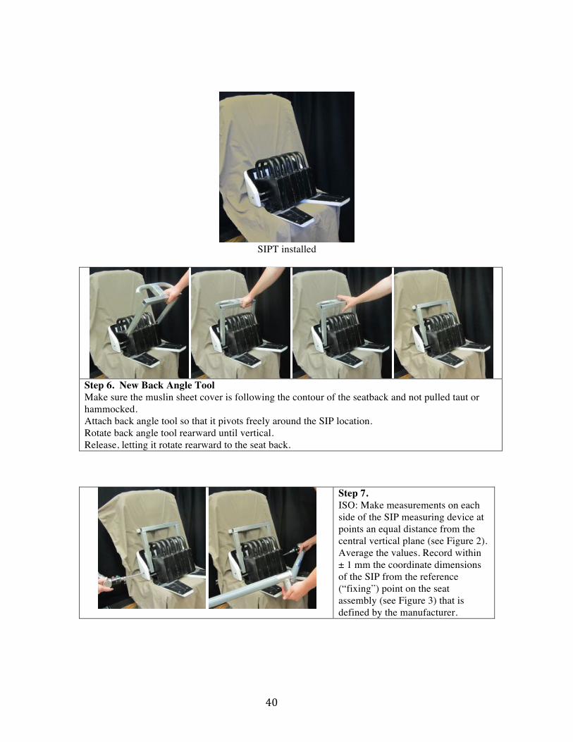
SIPT installed
Step 6. New Back Angle Tool Make sure the muslin sheet cover is following the contour of the seatback and not pulled taut or hammocked. Attach back angle tool so that it pivots freely around the SIP location. Rotate back angle tool rearward until vertical. Release, letting it rotate rearward to the seat back.
Step 7. ISO: Make measurements on each side of the SIP measuring device at points an equal distance from the central vertical plane (see Figure 2). Average the values. Record within ± 1 mm the coordinate dimensions of the SIP from the reference (“fixing”) point on the seat assembly (see Figure 3) that is defined by the manufacturer.
! 41!
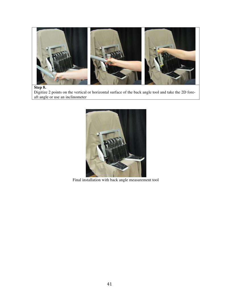
Step 8. Digitize 2 points on the vertical or horizontal surface of the back angle tool and take the 2D fore-aft angle or use an inclinometer
Final installation with back angle measurement tool
! 42!
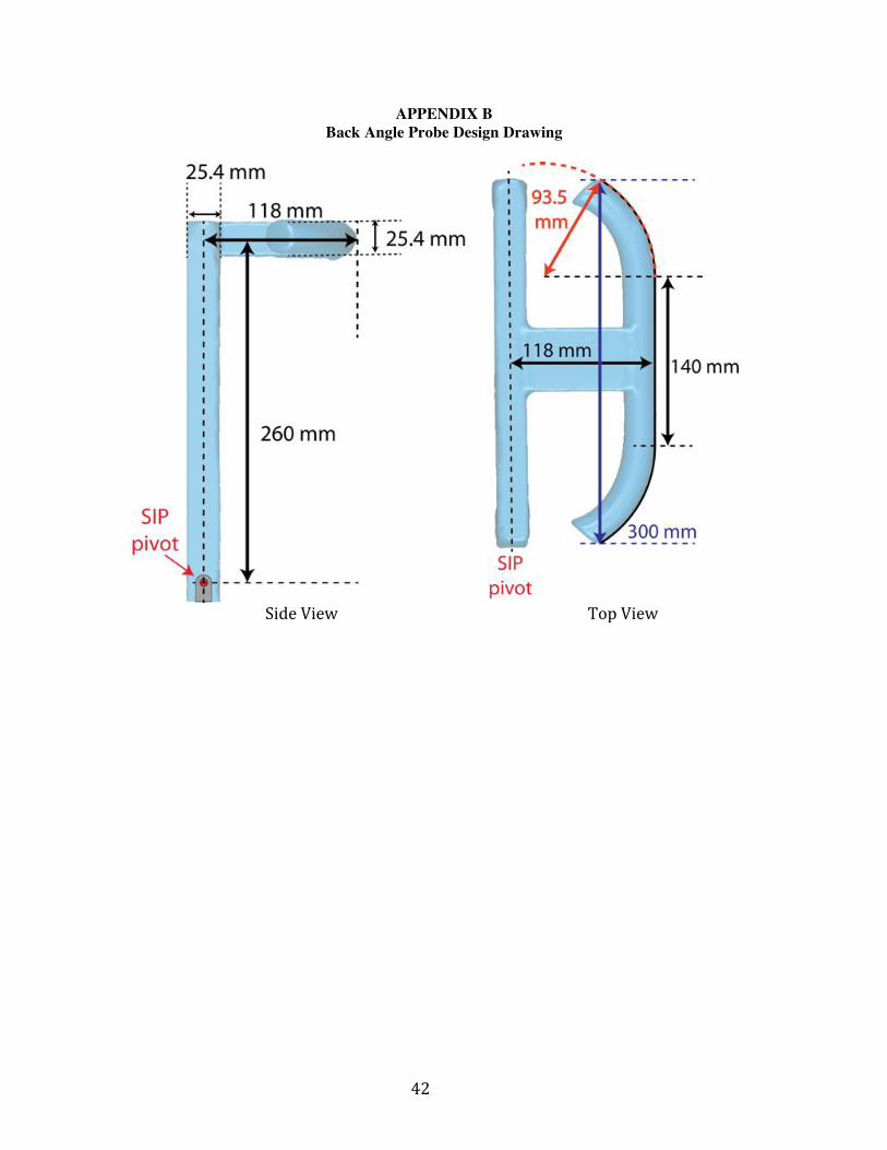
APPENDIX B Back Angle Probe Design Drawing
! !Side!View! Top!View!