materials, testing and evaluation
TRANSCRIPT

MATERIALS, TESTING AND EVALUATION Course code:ACEB08
II. B. Tech II semester Regulation: IARE R-18
BY Mr. K. Anand Goud
Associate Professors Mr. A. Jagadish Babu
DEPARTMENT OF CIVIL ENGINEERING INSTITUTE OF AERONAUTICAL ENGINEERING
(Autonomous) DUNDIGAL, HYDERABAD - 500 043
1

CO’s Course outcomes
CO1 Identify the different engineering materials, properties, manufacturing process of materials
CO2 Describe the mechanical behaviour and characteristics, elastic and plastic deformation of metals, strength properties and background of fracture mechanics.
CO3 Conduct mechanical testing of various metals like iron, steel and
various non-ferrous metals, impact testing, background of
fracture toughness of different materials, creep, fatigue.
2

COs Course Outcome
CO4 Understand the standard testing procedure of bricks, sand, concrete, soils, bitumen and bitumen mixes.
CO5 Describe the properties, mechanical behaviour of polymers, metals, composites, cementitious materials and special materials.
3

MODULE– I INTRODUCTION TO ENGINEERING MATERIALS
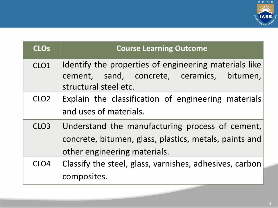
CLOs Course Learning Outcome
CLO1 Identify the properties of engineering materials like cement, sand, concrete, ceramics, bitumen, structural steel etc.
CLO2 Explain the classification of engineering materials
and uses of materials.
CLO3 Understand the manufacturing process of cement,
concrete, bitumen, glass, plastics, metals, paints and
other engineering materials.
CLO4 Classify the steel, glass, varnishes, adhesives, carbon
composites.
5

A cement is a binder, a substance used for construction that sets, hardens, and adheres to other materials to bind them together.
Cement is seldom used on its own, but rather to bind sand and gravel (aggregate) together.
Cement mixed with fine aggregate produces mortar for masonry, or with sand and gravel, produces concrete.
CEMENT

Different types of cements
Ordinary Portland Cement (OPC)
Portland Pozzolana Cement (PPC)
Rapid Hardening Cement
Quick setting cement
Low Heat Cement
Sulphates resisting cement
Blast Furnace Slag Cement
High Alumina Cement
White Cement
Air Entraining Cement
TYPES OF CEMENT

In usual construction work, Ordinary Portland Cement is widely used. The composition of Ordinary Portland Cement:
Argillaceous or silicates of alumina (clay and shale)
Calcareous or calcium carbonate (limestone, chalk, and marl)
Uses of Ordinary Portland Cement
It is used for general construction purposes.
It is also used in most of the masonry works.
Ordinary Portland Cement (OPC)
8

Pozzolanas are natural or synthetic materials that contain silica in reactive forms. It reacts with calcium hydroxide generated by hydrating cement to form additional cementations materials when it is finely divided.
The composition of Portland Pozzolana Cement:
OPC clinker
Gypsum
Pozzolanic Materials (Fly ash, volcanic ash, and Calcined clay or silica fumes.)
Portland Pozzolana Cement (PPC)
9

Uses of Portland Pozzolana Cement
PPC is usually used in hydraulic structures, marine structures, construction near the seashore, dam construction etc.
It is also used in pre-stressed and post-tensioned concrete members.
As it gives a better surface finish, it is used in decorative and art structures.
It is also used in the manufacture of precast sewage pipes.
10

When finely grounded Tri-calcium silicate (C3S) is present in OPC with higher content, it gains strength more quickly than OPC. This type of OPC is called Rapid Hardening Cement. It’s initial Setting Time 30 minutes and Final Setting Time 600 minutes.
Uses of Rapid Hardening Cement
Rapid hardening cement is mostly used where rapid construction is needed like the construction of pavement.
It also gives high strength.
Rapid Hardening Cement
11

Quick setting cement is the cement which sets in a very short time. The initial setting time is 5 minutes and the final setting time is 30 minutes. The composition of Quick Setting Cement:
Clinker
Aluminium sulphate (1% to 3% by weight of clinker)
The aluminium sulphte increase the hydration rate of silicate.
Uses of Quick Setting Cement
It is used in underwater construction.
It is also used in rainy & cold weather conditions.
It is used a higher temperature where water evaporates easily.
Used for anchoring or rock bolt mining and tunneling
Quick Setting Cement
12
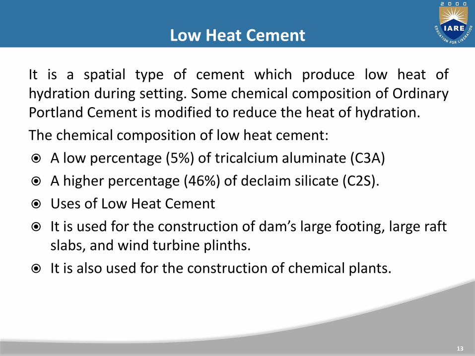
It is a spatial type of cement which produce low heat of hydration during setting. Some chemical composition of Ordinary Portland Cement is modified to reduce the heat of hydration.
The chemical composition of low heat cement:
A low percentage (5%) of tricalcium aluminate (C3A)
A higher percentage (46%) of declaim silicate (C2S).
Uses of Low Heat Cement
It is used for the construction of dam’s large footing, large raft slabs, and wind turbine plinths.
It is also used for the construction of chemical plants.
Low Heat Cement
13

Sulphate resisting cement is used to resist sulphet attacks in concrete. Due to the lower percentage of Tricalcium aluminate, the production of calcium sulpho-aluminates gets reduced.
Uses of Sulphates resisting Cement
Construction in contact with soils or groundwater having more than 0.2% or 0.3 % g/l sulphate salts respectively.
Concrete surfaces subjected to alternate wetting and drying such as bridge piers, concrete surface in tidal zone, apron, Building near seacoast.
Effluent treatment plans, Chimney, Chemical industries, water storage, sumps, drainage works, Cooling towers, Coastal protective works such as sea walls, breakwaters, tetrapods etc.
Sulphates resisting cement
14

High Alumina cement is obtained by mixing calcining bauxite (it’s an aluminium ore) and ordinary lime with clinker during the manufacture of OPC. In which the total amount of alumina content should not be lesser than 32% and it should maintain the ratio by weight of alumina to the lime between 0.85 to 1.30.
Uses of High Alumina Cement
It is used where concrete structures are subjected to high temperatures like workshop, refractory, foundries etc
It also used where the concrete is subjected to frost and acidic action.
High Alumina Cement
15

Air-entraining cement is a spatial type of cement which entrains tinny air bubbles in concrete. When water in concrete get frizzed due to low temperature, it expands. When air-entraining cement, the air voids in concrete provides space for water to expand without cracking concrete. But this type cement does not provide high strength in concrete.
Uses of Air-Entraining Cement
Spatially it is used in areas where the temperature is very low.
It also resists Sulphet attack.
It is used where the de-iceing chemical is used.
Air Entraining Cement
16

Sand is a granular material composed of finely divided rock and mineral particles. It is defined by size, being finer than gravel and coarser than silt. Sand can also refer to a textural class of soil or soil type; i.e., a soil containing more than 85 percent sand-sized particles by mass.
Sand is a non-renewable resource over human timescales, and sand suitable for making concrete is in high demand. Desert sand, although plentiful, is not suitable for concrete. 50 billion tons of beach sand and fossil sand is used each year for construction.
SAND
17
Sand is basically made of unconsolidated granular materials consisting of either rock fragments or mineral particles or oceanic materials. It is mainly made of silicate minerals and silicate rock granular particles. Typically quartz is the most dominant mineral here as it possesses highly resistant properties to weather.
Other common rock-forming minerals like amphiboles and micas also found in sand. Heavy minerals such as tourmaline, zircon etc can also be present in the sand in smaller concentration. But from a high level, most sand on the beach is made up of gray or tan quartz and feldspar.
COMPOSITION OF SAND
18
However, the most common mineral in the sand is quartz–also known as silicon dioxide. This is formed when silicon and oxygen combine. Feldspar is the most found group of minerals on the earth’s surface and forms about 65% of the terrestrial rocks. When the wind and sea whip up on the shores, they transport these teeny tiny granules to the beach and make up the sand with this combination.
COMPOSITION OF SAND
19

It is not possible to classify the sand in a type or simply in a way. Because there is no such thing as an official sand classification. Sand is a highly variable substance and therefore it is possible to make an attempt to classify it into separate categories.
1. Coral Sand: Coral sand has several meanings.
2. Glass Sand: This type of sand mainly consists of silicon dioxide. and this is the main element in this type of sand.
3. Immature Sand: Sand composed of the same minerals that made up its parent rocks.
Different Types of Sand
20

4. Gypsum Sand: This type of same mainly consists of Calcium sulfate dihydrate. (CaSO4·2H2O)
5. Ooid Sand: Ooids are rounded pellets, and are also spheroidal coated sedimentary grains. And this type of sand is formed by calcium carbonate.
6. Silica Sand: Silica sand is almost pure quartz.
7. Pit Sand: - Obtained by forming pits into the soil
- It is sharp, angular, porous and free from harmful salts
- Clay & other impurities should be washed and screened before using in engineering purpose.
- Fine pit sand, when rubbed between fingers, should not leave any stain on it. It indicates the presence of clay.
Different Types of Sand
21

8. River Sand: - Found at river beds and banks.
- Fine, round and polished due to rubbing action of water currents.
- Has less frictional strength because of roundness.
- Almost white in color.
- Grains are smaller than pit sand, and hence more suitable for plastering work.
- Normally available in pure condition and hence can be used for all kinds of Civil Engineering works.
Different Types of Sand
22

9. Sea Sand:- Obtained from seashores.
- Fine, rounded and polished due to rubbing action of water.
- Light brown in color.
- Worst of the three types of sand because of containing a lot of salts.
- Salts absorb moisture from the atmosphere and cause permanent dampness and efflorescence in the structure.
- Sea salt also retards the setting action of cement.
- Besides, it contains shells and organic matter which decompose in the body of mortar and concrete and hence reduce their life and strength.
- Sea sand should as far as possible be discarded
Different Types of Sand
23

10. Green Sand: Have some greenish materials.
11. Desert Sand: Which is found in the various desert.
12. Lithic Sand: Sometimes sand is composed of tiny rocks or comparatively more little, from this its formation its name is lithic sand.
13. Mixed Carbonate-silicate Sand: Some sand samples are a mixture of organic and inorganic sand grains.
Different Types of Sand
24

Concrete is a composite material in which a building material mixed in water on solidification binds the inert particles of well graded fine and coarse aggregates.
Cement and Lime are generally used as binding materials, where as sand cinder is used as fine aggregates and crushed stones, gravel, broken bricks, clinkers are used as coarse aggregates.
CONCRETE
25

Light weight Concrete High Density Concrete Plum Concrete No Fines Concrete Aerated Concrete Fiber Reinforced Concrete (FRC) Polymer Concrete Ferro Cement High Strength Concrete High Performance Concrete
26
Types of Special Concrete

The density of conventional concrete is in order of 2200 to 2600 kg/m3. This heavy self weight will make it uneconomical structural material. The dead weight of the structure made up of this concrete is large compared to the imposed load to be carried. The small reduction in dead weight for structural members like slab, beam and column in high rise buildings, results in considerable saving in money and man power.
Attempts have been made in the past to reduce the self weight of the concrete to increase the efficiency of concrete as a structural member. The light weight concrete with density in the range of 300 to 1900 kg/m3 have been successfully developed.
27
Light Weight Concrete

28
Light Weight Concrete

The light weight concrete offers the following Advantages:
Reduction of Dead Load
Smaller section of Structural members can be adopted
Lower haulage and handling costs
Increase in the progress of work
Reduction of foundation costs, particularly in the case of weak soil and tall structures.
Light Weight concrete has a lower thermal conductivity. In case of buildings where air conditioning is to be installed, the use of light weight concrete will result in better thermal comforts and lower power consumption.
29
Light Weight Concrete- Advantages
The use of light weight concrete gives an outlet for industrial wastes such as fly ash, clinkers, slag etc., which otherwise create problem for disposal.
It offers great fire resistance.
Light weight concrete gives overall economy.
The lower modulus of elasticity and adequate ductility of light weight concrete maybe advantageous in the seismic design of structures.
30
Light Weight Concrete- Advantages

The light Weight Concrete is achieved by three different ways:
By replacing the normal mineral aggregate, by cellular porous or light weight aggregate
By introducing air bubble in mortar this is known as “aerated concrete”.
By omitting sand fraction from the aggregate. This is known as ‘No Fines Concrete’.
31

32
Light Weight Aggregate Concrete

Natural light weight Aggregates:
Pumice: These are rocks of volcanic origin. They are light coloured or nearly white and has a fairly even texture of interconnected voids. Its bulk density is 500-800kg/m3.
Scoria: Scoria is light weight aggregate of volcanic origin, They are dark in colour It is slightly weaker than pumice.
Rice Husk: Use of rice husk or groundnut husk has been reported as light weight aggregate.
Saw Dust: Saw dust is used as light weight aggregate in the flooring and in the manufacture of precast elements. But the presence of carbohydrates in the wood, adversely affect the setting and hardening of Portland cement.
Diatomite: It is derived from the remains of microscopic aquatic plants called diatoms. It is also used as a pozzolonic material.
33
Light Weight Aggregates

34

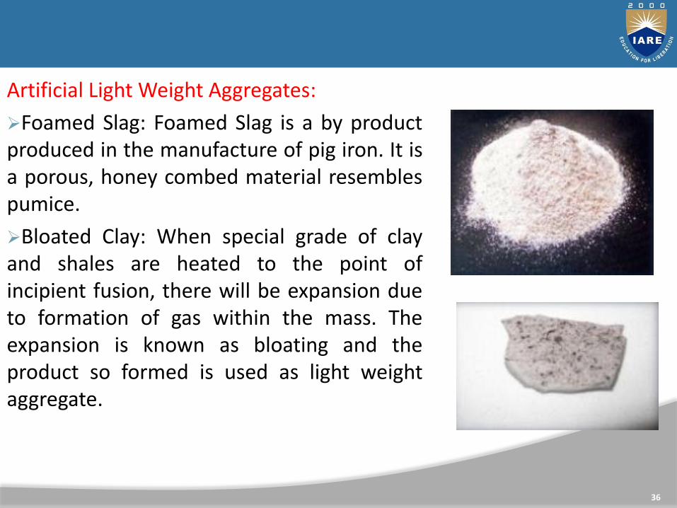
Artificial Light Weight Aggregates:
Sintered flash (Pulverised fuel ash)
The fly ash collected from modern thermal power plants burning pulverised fuel, is mixed with water and coal slurry in screw mixers and fed on to rotating pans, known as pelletizers, to form spherical pellets. The pellets are then fed on to a sinster strand at a temperature of 1000 ˚ C to 1200 ˚ C. Due to sinstering the fly ash particles coagulate to form hard brick like spherical particles. The produces material is screened and graded. In UK it is sold by the trade name ‘ Lytag’.
35
Artificial Light Weight Aggregates:
Foamed Slag: Foamed Slag is a by product produced in the manufacture of pig iron. It is a porous, honey combed material resembles pumice.
Bloated Clay: When special grade of clay and shales are heated to the point of incipient fusion, there will be expansion due to formation of gas within the mass. The expansion is known as bloating and the product so formed is used as light weight aggregate.
36

Artificial Light Weight Aggregates:
Exfoliated vermiculite: The raw vermiculite material resembles mica in appearance and consists of thin flat flakes containing microscopic particles of water. On heating with certain percentage of water it expands by delamination in the same way as that of slate or shale. This type of expansion is known as exfoliation. The concrete made with vermiculite as aggregate will have very low density and very low strength.
Ciders, clinkers, breeze: The partly fused or sintered particles arising from the combustion of coal, is termed as cinder or clinker or breeze. Cinder aggregate undergo high drying shrinkage and moisture movement. These are used for making building blocks for partition walls, for making screening over flat roofs and for plastering purposes.
37

Artificial Light Weight Aggregates
38
Exfoliated Vermiculite Clinkers

Concrete containing polymers can be classified into three categories namely:
(a) Polymer Impregnated Concrete (PIC)
(b) Polymer Portland Cement Concrete (PPCC)
(c) Polymer Concrete (PC)
39
Polymer Concrete

Polymer Impregnated Concrete is produced by impregnating or infiltrating a hardened Portland cement concrete with a monomer and subsequently Polymerizing the monomer in situ. It is one of the widely used polymer composite.
The partial or surface impregnation improves durability and chemical resistance while total or in-depth impregnation improves structural properties of concrete.
The monomer used for impregnation are: Methyl methacrylate (MMA)
Styrene
Acrylonitrile
T-butyl styrene
Epoxy
40
Polymer Impregnated Concrete (PIC)

41
Polymer Impregnated Concrete

Polymer portland cement concrete is a conventional portland cement concrete which is usually made by replacing a part of the mixing water with a latex (Polymer emulsion). Earlier latexes were based on poly vinyl acetate or polyvinylidence chloride, but these are seldom used now because of the risk of corrosion of steel in concrete in the lattercase and low wet strengths in the former.
Both elastomeric and glassy polymers have been employed in lattices.
42
Polymer Portland Cement Concrete (PPCC)
The latex systems for modifying cement concrete are now available in India. The latex generally contains about 50% by weight of spherical and very small polymer particles held in suspension in water by surface active agents. The presence of surface active agents in the latex tends to incorporate large amounts entrained air in concrete, therefore air detraining agents are usually added to commercial latexes. Since 10 to 25 percent polymer by weight of cement is used in typical latex modified concrete formulations, the addition of latex provides a large quantity of the needed mixing water in concrete. Therefore, latex modified concrete is made with as low an addition of extra mixing water as possible.
43
Polymer Portland Cement Concrete (PPCC)

44
Polymer Portland Cement Concrete (PPCC)

Background:
The word ceramic is derived from the greek term keramos, means “Potters Clay” and keramikos means “Clay Products”.
Till 1950’s the most important types of ceramics were the traditional clays, made into pottery , bricks, tiles etc.,
Ceramic artifacts play an important role in historical understanding of the technology and culture of the people who lived many years ago.
45
Ceramics

A ceramic material is an inorganic, non-metallic material and is often crystalline.
Traditional ceramics are clays.
The earliest was in pottery.
Most recently, different types of ceramics used are alumina, silicon carbide etc.,
Latest advancements are in the bio-ceramics with examples being dental implants and synthetic bones.
46
Ceramics

Pottery products, Sanitary ware, floor and roof tiles.
Crucibles, kiln linings, other refractories
High end applications such as in ceramic matrix composites, tiiles in space shuttle, bullet proof jackets, disk brakes, ball bearing applications, bio-ceramics.
47
Applications


CLOs Course Learning Outcome
CLO5 Explain the mechanical behaviour and characteristics
of different metals.
CLO6 Analyze the importance of elasticity principle,
characteristics and plastic deformation of metals.
CLO7 Explain standards for different materials, stress-
strain interpretation.
CLO8 Describe the fundamentals of internal friction,
creep, brittle fracture of steel.
CLO9 Understand the concept of fatigue of materials,
structural integrity assessment procedure.
49

Elastic Material:
A material which regains its original size and shape on removal of stress is said to be elastic material.
Plastic Material:
A material which can undergo permanent deformation without rupture is said to be plastic material. This property of material is known as plasticity. Plasticity is important when a material is to be mechanically formed by causing the material to flow.
50
Mechanical Properties of Materials

Ductile Material:
A material which can undergo considerable deformation without rupture is said to be ductile material. The major portion of deformation is plastic.
Brittle Material:
A material which ruptures with little or no plastic deformation is said to be brittle material.
51
Mechanical Properties of Materials

52
Concept of Stress - Strain

53
Stress and Strain

54
Stress and Strain

1.Modulus of Elasticity
2.Yield Strength of 0.2 % Offset
3.Ultimate tensile Strength
4.Percent elongation at fracture
5.Percent reduction in area at fracture
55
Tensile Test

Hardness: a measure of the resistance of a material to plastic (permanent) deformation.
Measured by indentation
• indenter material (ball, pyramid, cone) is harder than the material being tested (i.e.: tungsten carbide, diamond)
• indenter is pressed at 90o
• hardness is based on the depth of the impression or its cross sectional area.
56
Hardness

57
Hardness tests: Hardness numbers

Syllabus
Introduction:
Fracture mechanics is all about cracks; stress fields around cracks, stress intensity factors at cracks, failures due to cracks, growth rates of cracks, etc. This website covers all of these topics, beginning with some historical perspective for motivation.
Failures have occurred for many reasons, including uncertainties in the loading or environment, defects in the materials, inadequacies in design, and deficiencies in construction or maintenance.
Fracture mechanics

Syllabus
The Module on the Dislocation Basis of Yield (Module 21) shows how the strength of structural metals – particularly steel – can be increased to very high levels by manipulating the microstructure so as to inhibit dislocation motion.
Unfortunately, this renders the material increasingly brittle, so that cracks can form and propagate catastrophically with very little warning. An unfortunate number of engineering disasters are related directly to this phenomenon, and engineers involved in structural design must be aware of the procedures now available to safeguard against brittle fracture.

Syllabus
The stress intensity approach

Syllabus
Stress State Schematics
The first sketch here plots the hoop stress, σθθσθθ at θ=±90∘θ=±90∘ as a function of rr.
It shows the factor-of-three concentration at the hole's edge and how it quickly dissipates away with increasing The stress concentration is small again at one diameter distance from the hole's edge, and indeed negligible at two diameters distance.
In finite element analyses, this steep gradient necessitates a very fine mesh in the radial direction in order to accurately model the stress and strain field.

Syllabus
stress concentration

Syllabus
Fracture Toughness
Fracture toughness is an indication of the amount of stress required to propagate a preexisting flaw.
It is a very important material property since the occurrence of flaws is not completely avoidable in the processing, fabrication, or service of a material/component.
Flaws may appear as cracks, voids, metallurgical inclusions, weld defects, design discontinuities, or some combination thereof.

Syllabus
Since engineers can never be totally sure that a material is flaw free, it is common practice to assume that a flaw of some chosen size will be present in some number of components and use the linear elastic fracture mechanics (LEFM) approach to design critical components.

MODULE III STANDARD TESTING & EVALUATION
PROCEDURES

66
CLOs Course Learning Outcome
CLO 10 Perform the mechanical testing of various metals like
iron, steel and non-ferrous metals.
CLO 11 Explain elastic deformation and plastic deformation
of metals.
CLO 12 Understand the impact testing, fatigue and creep of
materials.
CLO 13 Explain fracture toughness of different materials like
steel and non-ferrous metals

Properties of Structural Steel
Properties of structural steel include:
Tensile properties
Shear properties
Hardness
Creep
Relaxation
Fatigue

Tensile Properties of Structural Steel
There are different categories of steel structures which can be used in the construction of steel buildings.
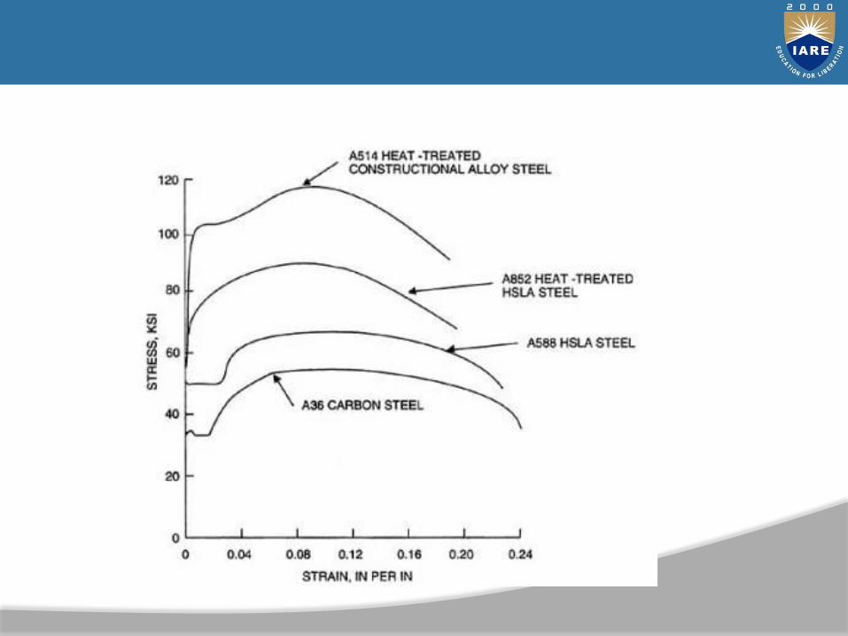
Typical stress strain curves for various classes of structural steel, which are derived from steel tensile test.
The initial part of the curve represents steel elastic limit. In this range, steel structure deformation is not permanent, and the steel regain its original shape upon the removal of the load.

Shear Properties of Structural Steel
Shear strength of steel structure is specified at the failure under shear stress and it is about 0.57 times yield stress of structural steel.
Regarding elastic shear modulus, it is expressed as the ratio of shear stress to shear strain in elastic range of steel structure.
Structural Steel Relaxation
It is a step by step reduction of structural steel under a constant stress. Usually, yield strength of steel structure increases around 5% over stress relieved strain and the steel structure would suffer from plastic elongation which around 0.01.

Hardness of Structural Steel
Hardness is the measure of ability of steel structure to withstand inelastic deformation. Standard test methods and definitions for mechanical testing of steel products (A370-05) specify three different tests to evaluate steel hardness namely: Brinell, Rockwell and portable.
Any of these tests can be used to estimate steel structure hardness. Not only is the steel structure hardness used to examine the uniformity of different products but also to evaluate steel tensile strength.

Creep of Structural Steel Relaxation
Creep is gradual variation of strain of steel structure under constant stress. It occurs due to the influence of constant stress and the effect of fire.
Creep property is insignificant for structural steel frame design and construction apart from the case in which the effect of fire should be taken into consideration.
Fatigue of Structural Steel
Fatigue is the failure of steel structure due to crack initiation and development under the influence of cyclic loading. Various tests are available to evaluate structural steel fatigue such as flexure test, rotating beam test and axial load test.

• An impact test is used to observe the mechanics that a material will exhibit when it experiences a shock loading that causes the specimen to immediately deform, fracture or rupture completely.
• To perform this test the sample is placed into a holding fixture with the geometry and orientation determined by the type of test that is used and then a known weight generally but not always in the shape of a pendulum is released from a known height so that it collides with the specimen with a sudden force.
• This collision between the weight and specimen generally results in the destruction of the specimen but the transfer of energy between the two is used to determine the fracture mechanics of the material.
73
Impact Test

• The purpose of an impact test is to determine the ability of the material to absorb energy during a collision.
• This energy may be used to determine the toughness, impact strength, fracture resistance, impact resistance or fracture resistance of the material depending on the test that was performed and the characteristic that is to be determined.
• These values are important for the selection of materials that will be used in applications that require the material to undergo very rapid loading processes such as in vehicular collisions.
74
Purpose of Impact Test

• For a single impact test the three most popular types of test are the Charpy V-notch test, the Izod test and the Tensile Impact test.
• These three tests all essentially determine the same characteristics of the material but differ in the orientation of the test sample which causes the sample to be stressed in different directions and involve a known weight released from a known height colliding with the specimen in its test fixture.
• All of these tests are useful in determining the impact mechanics of the test specimen.
75
Types of Impact Tests
• Nearly all materials may benefit from impact testing, but the most common types used are metals, plastics, woods, composites, ceramics, and polymers.
• Generally these materials take the form of sheets of varying thicknesses or short rods depending on the test. However, most materials will experience either ductile or brittle failure depending of the type of test, the rate of loading and the temperature of the sample.
• Brittle failure of a material requires a small amount of energy to begin the crack or to cause the crack to grow until the sample fails. On the other hand, ductile failure of a material requires a much higher load to initiate and propagate the crack until failure.
76
Types of materials for Impact Tests

Fracture mechanics is a methodology that is used to predict and diagnose failure of a part with an existing crack or flaw. The presence of a crack in a part magnifies the stress in the vicinity of the crack and may result in failure prior to that predicted using traditional strength-of-materials methods.
The traditional approach to the design and analysis of a part is to use strength-of-materials concepts. In this case, the stresses due to applied loading are calculated. Failure is determined to occur once the applied stress exceeds the material's strength (either yield strength or ultimate strength, depending on the criteria for failure).
77
Fracture Mechanics- Background

In fracture mechanics, a stress intensity factor is calculated as a function of applied stress, crack size, and part geometry.
Failure occurs once the stress intensity factor exceeds the material's fracture toughness.
At this point the crack will grow in a rapid and unstable manner until fracture.
Fatigue of a material
In materials science, fatigue is the progressive and localised structural damage that occurs when a material is subjected to cyclic loading. The maximum stress values are less than the ultimate tensile stress limit, and may be below the yield stress limit of the material.
78
Fracture Mechanics- Background

● The process starts with dislocation movements, eventually forming persistent slip bands that nucleate short cracks.
● The greater the applied stress, the shorter the life.
● Damage is cumulative. Materials do not recover when rested.
● Fatigue is a stochastic process, often showing considerable scatter. Fatigue life scatter tends to increase for longer fatigue lives.
● Fatigue life is influenced by a variety of factors, such as temperature, surface finish, presence of oxidizing or inert chemicals, residual stresses, contact (fretting), etc.
79
Characteristics of Fatigue

● Some materials (e.g., some steel and titanium alloys) exhibit a theoretical fatigue limit below which continued loading does not lead to failure.
● In recent years, researchers have found that failures occur below the theoretical fatigue limit at very high fatigue lives (109 to 1010 cycles). An ultrasonic resonance technique is used in these experiments with frequencies around 10-20 kHz.
● High cycle fatigue strength (about 103 to 108 cycles) can be described by stress based parameters. A load-controlled, servo-hydraulic test rig is commonly used in these tests, with frequencies of around 20-50 Hz. Other sort of machines like resonant magnetic machines can also be used, achieving frequencies up to 250Hz.
80
Characteristics of Fatigue

Creep is the term used to describe the tendency of a 'solid' material to slowly deform permanently to relieve stresses. It occurs as a result of long term exposure to levels of stress that are below the yield strength or ultimate strength of the material. Creep is more severe in materials that are subjected to heat for long periods, and near the melting point.
81
Creep

MODULE-IVSTANDARD TESTING PROCEDURES

83
CLOs Course Learning Outcome
CLO 14 Explain the testing procedures of bricks and sand.
CLO 15 Describe the testing procedures of fresh and hardened
concrete.
CLO 16 Understand the properties of soil by conducting the
different tests.
CLO 17 Explicate the procedures of testing bitumen and bitumen
mixes.

• Various types of tests on bricks are conducted to check the qualities of bricks for construction purposes.
Tests on bricks are conducted at construction site as well as in laboratory.
Bricks are oldest and important construction materials because of their durability, reliability, strength and low cost.
84
Types of Tests on Bricks

Following tests are conducted on bricks to determine its suitability for construction work:
Absorption test
Crushing strength test
Hardness test
Shape and size
Color test
Soundness test
Structure of brick
Presence of soluble salts (Efflorescence Test)
85
Types of Tests on Bricks

• Absorption test is conducted on brick to find out the amount of moisture content absorbed by brick under extreme conditions.
• In this test, sample dry bricks are taken and weighed. After weighing these bricks are placed in water with full immersing for a period of 24 hours.
• Then weigh the wet brick and note down its value. The difference between dry and wet brick weights will give the amount of water absorption.
86
Absorption Test on Bricks

Absorption Test on Bricks
• For a good quality brick the amount of water absorption should not exceed 20% of weight of dry brick.

• Crushing strength of bricks is determined by placing brick in compression testing machine. After placing the brick in compression testing machine, apply load on it until brick breaks.
• Note down the value of failure load and find out the crushing strength value of brick. Minimum crushing strength of brick is 3.50N/mm2.if it is less than 3.50 N/mm2, then it is not useful for construction purpose.
88
Compressive Strength Test on Bricks

A good brick should resist scratches against sharp things. So, for this test a sharp tool or finger nail is used to make scratch on brick. If there is no scratch impression on brick then it is said to be hard brick.
89
Hardness Test on Bricks

Shape and size of bricks are very important consideration. All bricks used for construction should be of same size.
The shape of bricks should be purely rectangular with sharp edges. Standard brick size consists length x breadth x height as 19cm x 9cm x 9cm.
To perform this test, select 20 bricks randomly from brick group and stack them along its length , breadth and height and compare. So, if all bricks similar size then they are qualified for construction work.
90
Shape and Size Test on Bricks

A good brick should possess bright and uniform color throughout its body.
91
Color Test on Bricks

Soundness test of bricks shows the nature of bricks against sudden impact. In this test, 2 bricks are chosen randomly and struck with one another. Then sound produced should be clear bell ringing sound and brick should not break. Then it is said to be good brick.
92
Soundness Test on Bricks

To know the structure of brick, pick one brick randomly from the group and break it. Observe the inner portion of brick clearly. It should be free from lumps and homogeneous.
93
Structure of Bricks
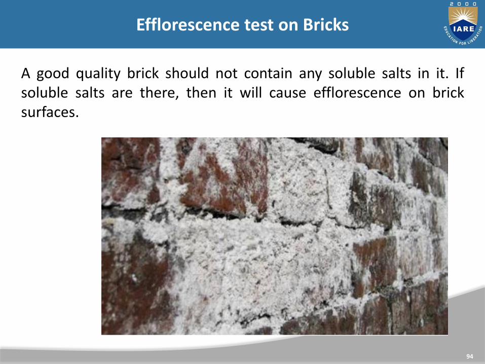
A good quality brick should not contain any soluble salts in it. If soluble salts are there, then it will cause efflorescence on brick surfaces.
94
Efflorescence test on Bricks
To know the presence of soluble salts in a brick, placed it in a water bath for 24 hours and dry it in shade. After drying, observe the brick surface thoroughly. If there is any white or grey color deposits, then it contains soluble salts and not useful for construction.
95
Efflorescence test on Bricks

• A good quality brick should not contain any soluble salts in it. If soluble salts are there, then it will cause efflorescence on brick surfaces.
• To know the presence of soluble salts in a brick, placed it in a water bath for 24 hours and dry it in shade.
• After drying, observe the brick surface thoroughly.
If there is any white or grey color deposits, then it contains soluble salts and not useful for construction.
96
Efflorescence test on Bricks

MODULE-VTESTING PROCEDURES OF SPECIAL MATERIALS

98
CLOs Course Learning Outcome
CLO 18 Understand the testing procedures of polymers and
polymer based materials.
CLO 19 Explain the behaviour of metals under various loads
CLO 20 Describe the mechanical behaviour of composite
materials.
CLO 21 Discuss the properties of cementitious materials like fly
ash, blast furnace slag.

Concrete containing polymers can be classified into three categories namely:
(a) Polymer Impregnated Concrete (PIC)
(b) Polymer Portland Cement Concrete (PPCC)
(c) Polymer Concrete (PC)
99
Polymer Concrete

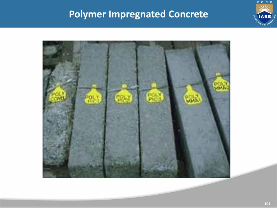
Polymer Impregnated Concrete is produced by impregnating or infiltrating a hardened Portland cement concrete with a monomer and subsequently Polymerizing the monomer in situ. It is one of the widely used polymer composite.
The partial or surface impregnation improves durability and chemical resistance while total or in-depth impregnation improves structural properties of concrete.
The monomer used for impregnation are: Methyl methacrylate (MMA)
Styrene
Acrylonitrile
T-butyl styrene
Epoxy
100
Polymer Impregnated Concrete (PIC)
101
Polymer Impregnated Concrete

Polymer portland cement concrete is a conventional portland cement concrete which is usually made by replacing a part of the mixing water with a latex (Polymer emulsion). Earlier latexes were based on poly vinyl acetate or polyvinylidence chloride, but these are seldom used now because of the risk of corrosion of steel in concrete in the lattercase and low wet strengths in the former.
Both elastomeric and glassy polymers have been employed in lattices.
102
Polymer Portland Cement Concrete (PPCC)

• The latex systems for modifying cement concrete are now available in India. The latex generally contains about 50% by weight of spherical and very small polymer particles held in suspension in water by surface active agents.
• The presence of surface active agents in the latex tends to incorporate large amounts entrained air in concrete, therefore air detraining agents are usually added to commercial latexes. Since 10 to 25 percent polymer by weight of cement is used in typical latex modified concrete formulations, the addition of latex provides a large quantity of the needed mixing water in concrete.
103
Polymer Portland Cement Concrete (PPCC)

104
Polymer Portland Cement Concrete (PPCC)

Destructive Testing :
In this kind of testing, the material undergoes mechanical testing and is discarded thereafter. Test results are compared with specifications. Subtypes include:
Bend test
Impact test – Further categorised as Charpy test and Izod test
Hardness test
Tensile test
Fatigue test
Corrosion resistance test
Wear test

Non-Destructive Testing :
Raw and finished material undergoes testing according to code specifications such as ASME Boiler and Pressure Vessel Code Section V. The tested material is not damaged by the test. Subtypes include:
Visual testing
Dye penetrate inspection
Magnetic particle inspection
Radiographic testing

Ultrasonic testing
Leak testing
Eddy current testing
Remote field electromagnetic testing
LR UT

Composites are combinations of two more separate materials on a microscopic level, in a controlled manner to give desired properties.
The properties of a composite will be different from those of the constituents in isolation.
When two materials are combined together to form a composite, one of the materials will be in “Reinforcing phase” and the other material will be in “Matrix phase”. Typically, reinforcing material in the form of fibres, sheets or particles are strong with low densities while the matrix is usually a ductile or tough material.
Eg.: Glass -> Reinforcing material
Polyester -> Matrix material
Glass + Polyester -> GRP (Glass fibre reinforced plastic)
Composite Materials

Classification
Composites can be broadly classified in to two groups. They are,
1. Natural composites
2. Man-made composites
Several natural materials can be grouped under natural composites.
Eg.: Bone, Wood etc.,

Man-made composites are produced by combining two or more materials in definite proportions under controlled conditions.
Eg.:
1. Mud mixed straw to produce stronger mud mortar and bricks.
2. Ferro-cement
3. Concrete and RCC
4. Plywood, Chipboards, Decorative laminates
5. Asbestos Cement Sheets
6. Reinforced Glass
7. Fibre Reinforced Plastic (FRP)
8. Carbon Composites

Properties of Composites
1. Composites posses excellent strength and stiffness
2. They are very light materials
3. They possess high resistance to corrosion, chemicals and other weathering agents.
4. They can be moulded to any shape and size with required mechanical properties in different directions

Disadvantages of composites
1. High production cost
2. Difficult to repair
3. Susceptible to damage
Uses of composite materials
1. Extensively used in space technology and production of commercial air-planes.
2. Used in the production of sport goods.
3. Used for general industrial and engineering structures
4. Used in high speed and fuel efficient transport vehicles
Applications in the field of Civil Engineering
Composites are extensively used in the field of Civil Engineering. Ferro-cement is a good example for composite. R.C.C. and P.S.C. (Pre-stressed Cement Concrete) are composites that are widely used for structural components.
Even concrete can be considered as a composite. Block boards, Batten boards, and Chip boards which are composites are used in light construction works such as doors, windows, furniture and cabinets.
Asbestos Cement Sheets are used as roofing material. Reinforced glass is used for sky-lights and door and window panelling.

Fly ash
Fly ash is a heterogeneous by-product material produced in the combustion process of coal used in power stations. It is a fine grey coloured powder having spherical glassy particles that rise with the flue gases. As fly ash contains pozzolanic materials components which reach with lime to form cementatious materials. Thus Fly ash is used in concrete, mines, landfills and dams.
cementitious materials
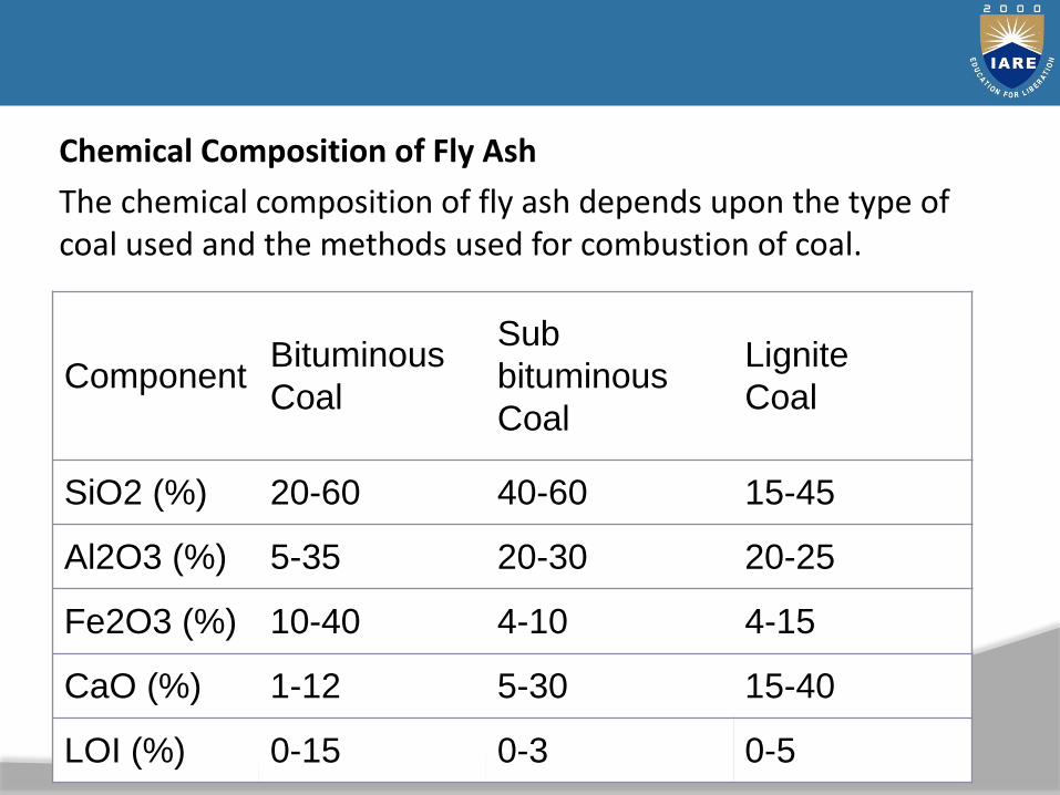
Chemical Composition of Fly Ash
The chemical composition of fly ash depends upon the type of coal used and the methods used for combustion of coal.
Component Bituminous
Coal
Sub
bituminous
Coal
Lignite
Coal
SiO2 (%) 20-60 40-60 15-45
Al2O3 (%) 5-35 20-30 20-25
Fe2O3 (%) 10-40 4-10 4-15
CaO (%) 1-12 5-30 15-40
LOI (%) 0-15 0-3 0-5

Physical Properties of Fly Ash
The physical properties of fly ash are,
1. Fineness of Fly Ash
As per ASTM, the fineness of the fly ash is to be checked in both dry n wet sieving. The fly ash sample is sieved in 45 micron sieve and the percentage of retained on the 45 micron sieve is calculated. Further fineness is also measured by LeChatelier method and Blaine Specific
Surface method.

2. Specific Gravity of Fly Ash
The specific gravity of fly ash ranges from a low value of 1.90 for a sub-bituminous ash to a high value of 2.96 for an iron-rich bituminous ash.
3. Size and Shape of Fly Ash
As the flyash is a very fine material, the particle size ranges in between 10 to 100 micron. The shape of the fly ash is usually spherical glassy shaped.